Embed Size (px)
Citation preview
CATIA Version 6 Release 2013x
FACT SHEET The Digital Product Experience
Table of contents Value at a glance
CATIA V6R2013x Overview
CATIA Version 6 Release 2013x Enhancements
Where to find more information
3D
S.C
OM
© D
assa
ult S
ystè
me
s
| C
on
fide
ntia
l In
form
atio
n
| 0
1/0
2/2
01
2 re
f.:
Docu
me
nt_
Refe
ren
ce
|
2
3D
S.C
OM
© D
assa
ult S
ystè
me
s
| C
on
fide
ntia
l In
form
atio
n
| 0
1/0
2/2
01
2 re
f.:
Docu
me
nt_
Refe
ren
ce
|
Value at a glance
CATIA Version 6 LEVERAGES THE CAPACITY OF INNOVATION FOR COMPANIES OF
ALL SIZES IN ALL INDUSTRIES BY DELIVERING BREAKTHROUGH PRODUCTIVITY
DESIGN SOLUTIONS POWERED BY A HIGHLY COLLABORATIVE PLATFORM
As the 3DEXPERIENCE Company, Dassault Systèmes provides business and people with
virtual universes to imagine sustainable innovations. Digitizing products and environments
opens up new frontiers for all participants involved in a product‟s life, from creation to usage.
Realistic experiences allow users to anticipate product behavior and impact on the
environment, thus creating the conditions for sustainable innovation.
The 3DEXPERIENCE Platform transforms innovation by connecting designers, engineers,
marketing managers and even consumers, in a new „social enterprise‟. It powers Dassault
Systèmes‟ Brand Applications, including CATIA, to deliver the full capabilities of 3D
Modeling, Content & Simulation, Social & Collaborative innovation and Information
Intelligence for industry leaders to build the right business value and experiences for their
ultimate consumers.
More and more products are now a combination of physical, software and electronics, in
other words, “smart products”. This creates increasing pressure on all the specialists who
must create these products, not only individually, in terms of their respective disciplines, but
collectively. Designers, Engineers, Systems & Product Architects and Systems Engineers
need multi-disciplinary collaboration like never before in the development of products.
The mission of CATIA is to serve this population. CATIA provides unparalleled user
experiences which accelerate the innovation potential in creative design, engineering,
systems & product architecture and systems engineering.
The CATIA Digital Product Experience:
The combination the Digital Mockup and the Functional Mock Up makes it possible to
experience a product in its geometric as well as its functional view to realize the full product
experience. This is the CATIA Digital Product Experience (DPE).
The DPE process is deployed to 4 communities of users:
Designers
o Create the shape and attractiveness of the product.
Scientists
o Create the proper functional behavior of smart products and components.
Engineers
o Responsible for the end-to-end process to ensure the product can be
manufactured.
Architects
o Define the product and systems architecture and develop concepts.
3
3D
S.C
OM
© D
assa
ult S
ystè
me
s
| C
on
fide
ntia
l In
form
atio
n
| 0
1/0
2/2
01
2 re
f.:
Docu
me
nt_
Refe
ren
ce
|
CATIA Version 6 R2013x Overview
CATIA Designer
Community
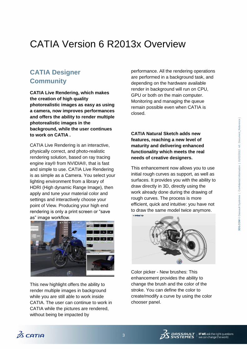
CATIA Live Rendering, which makes
the creation of high quality
photorealistic images as easy as using
a camera, now improves performances
and offers the ability to render multiple
photorealistic images in the
background, while the user continues
to work on CATIA .
CATIA Live Rendering is an interactive,
physically correct, and photo-realistic
rendering solution, based on ray tracing
engine iray® from NVIDIA®, that is fast
and simple to use. CATIA Live Rendering
is as simple as a Camera. You select your
lighting environment from a library of
HDRI (High dynamic Range Image), then
apply and tune your material color and
settings and interactively choose your
point of View. Producing your high end
rendering is only a print screen or “save
as” image workflow.
This new highlight offers the ability to
render multiple images in background
while you are still able to work inside
CATIA. The user can continue to work in
CATIA while the pictures are rendered,
without being be impacted by
performance. All the rendering operations
are performed in a background task, and
depending on the hardware available
render in background will run on CPU,
GPU or both on the main computer.
Monitoring and managing the queue
remain possible even when CATIA is
closed.
CATIA Natural Sketch adds new
features, reaching a new level of
maturity and delivering enhanced
functionality which meets the real
needs of creative designers.
This enhancement now allows you to use
initial rough curves as support, as well as
surfaces. It provides you with the ability to
draw directly in 3D, directly using the
work already done during the drawing of
rough curves. The process is more
efficient, quick and intuitive: you have not
to draw the same model twice anymore.
Color picker - New brushes: This
enhancement provides the ability to
change the brush and the color of the
stroke. You can define the color to
create/modify a curve by using the color
chooser panel.
4
3D
S.C
OM
© D
assa
ult S
ystè
me
s
| C
on
fide
ntia
l In
form
atio
n
| 0
1/0
2/2
01
2 re
f.:
Docu
me
nt_
Refe
ren
ce
|
Dimension and Position pictures: Natural
Sketch allows the placement of images
into the 3D world to be used as models or
supports. This enhancement allows you to
accurately size, measure, scale and
position the images in the 3D
environment. You have the ability to put
some dimensions on pictures and to
position them according to each other's
position.
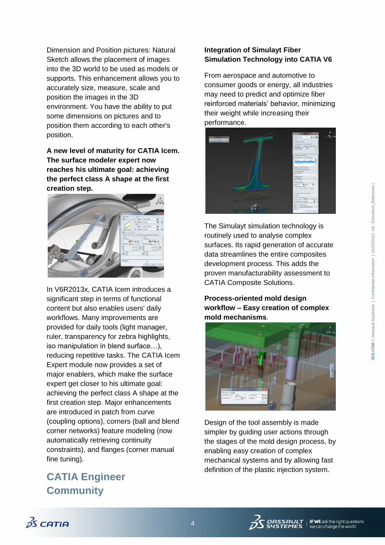
A new level of maturity for CATIA Icem.
The surface modeler expert now
reaches his ultimate goal: achieving
the perfect class A shape at the first
creation step.
In V6R2013x, CATIA Icem introduces a
significant step in terms of functional
content but also enables users' daily
workflows. Many improvements are
provided for daily tools (light manager,
ruler, transparency for zebra highlights,
iso manipulation in blend surface…),
reducing repetitive tasks. The CATIA Icem
Expert module now provides a set of
major enablers, which make the surface
expert get closer to his ultimate goal:
achieving the perfect class A shape at the
first creation step. Major enhancements
are introduced in patch from curve
(coupling options), corners (ball and blend
corner networks) feature modeling (now
automatically retrieving continuity
constraints), and flanges (corner manual
fine tuning).
CATIA Engineer
Community
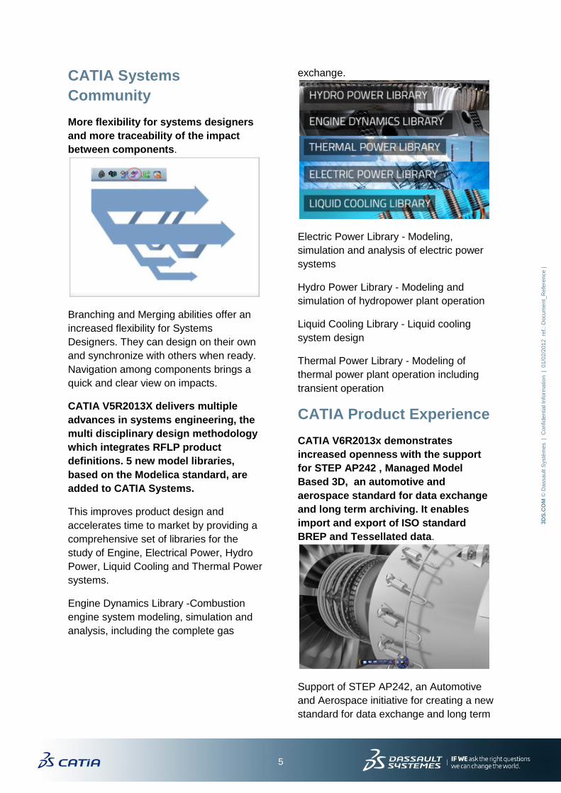
Integration of Simulayt Fiber
Simulation Technology into CATIA V6
From aerospace and automotive to
consumer goods or energy, all industries
may need to predict and optimize fiber
reinforced materials‟ behavior, minimizing
their weight while increasing their
performance.
The Simulayt simulation technology is
routinely used to analyse complex
surfaces. Its rapid generation of accurate
data streamlines the entire composites
development process. This adds the
proven manufacturability assessment to
CATIA Composite Solutions.
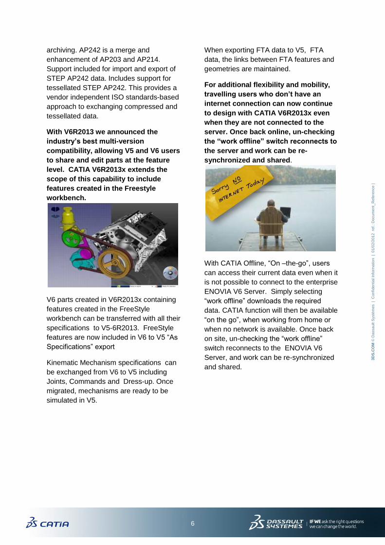
Process-oriented mold design
workflow – Easy creation of complex
mold mechanisms.
Design of the tool assembly is made
simpler by guiding user actions through
the stages of the mold design process, by
enabling easy creation of complex
mechanical systems and by allowing fast
definition of the plastic injection system.
5
3D
S.C
OM
© D
assa
ult S
ystè
me
s
| C
on
fide
ntia
l In
form
atio
n
| 0
1/0
2/2
01
2 re
f.:
Docu
me
nt_
Refe
ren
ce
|
CATIA Systems
Community
More flexibility for systems designers
and more traceability of the impact
between components.
Branching and Merging abilities offer an
increased flexibility for Systems
Designers. They can design on their own
and synchronize with others when ready.
Navigation among components brings a
quick and clear view on impacts.
CATIA V5R2013X delivers multiple
advances in systems engineering, the
multi disciplinary design methodology
which integrates RFLP product
definitions. 5 new model libraries,
based on the Modelica standard, are
added to CATIA Systems.
This improves product design and
accelerates time to market by providing a
comprehensive set of libraries for the
study of Engine, Electrical Power, Hydro
Power, Liquid Cooling and Thermal Power
systems.
Engine Dynamics Library -Combustion
engine system modeling, simulation and
analysis, including the complete gas
exchange.
Electric Power Library - Modeling,
simulation and analysis of electric power
systems
Hydro Power Library - Modeling and
simulation of hydropower plant operation
Liquid Cooling Library - Liquid cooling
system design
Thermal Power Library - Modeling of
thermal power plant operation including
transient operation
CATIA Product Experience
CATIA V6R2013x demonstrates
increased openness with the support
for STEP AP242 , Managed Model
Based 3D, an automotive and
aerospace standard for data exchange
and long term archiving. It enables
import and export of ISO standard
BREP and Tessellated data.
Support of STEP AP242, an Automotive
and Aerospace initiative for creating a new
standard for data exchange and long term
6
3D
S.C
OM
© D
assa
ult S
ystè
me
s
| C
on
fide
ntia
l In
form
atio
n
| 0
1/0
2/2
01
2 re
f.:
Docu
me
nt_
Refe
ren
ce
|
archiving. AP242 is a merge and
enhancement of AP203 and AP214.
Support included for import and export of
STEP AP242 data. Includes support for
tessellated STEP AP242. This provides a
vendor independent ISO standards-based
approach to exchanging compressed and
tessellated data.
With V6R2013 we announced the
industry’s best multi-version
compatibility, allowing V5 and V6 users
to share and edit parts at the feature
level. CATIA V6R2013x extends the
scope of this capability to include
features created in the Freestyle
workbench.
V6 parts created in V6R2013x containing
features created in the FreeStyle
workbench can be transferred with all their
specifications to V5-6R2013. FreeStyle
features are now included in V6 to V5 “As
Specifications” export
Kinematic Mechanism specifications can
be exchanged from V6 to V5 including
Joints, Commands and Dress-up. Once
migrated, mechanisms are ready to be
simulated in V5.
When exporting FTA data to V5, FTA
data, the links between FTA features and
geometries are maintained.
For additional flexibility and mobility,
travelling users who don’t have an
internet connection can now continue
to design with CATIA V6R2013x even
when they are not connected to the
server. Once back online, un-checking
the “work offline” switch reconnects to
the server and work can be re-
synchronized and shared.
With CATIA Offline, “On –the-go”, users
can access their current data even when it
is not possible to connect to the enterprise
ENOVIA V6 Server. Simply selecting
“work offline” downloads the required
data. CATIA function will then be available
“on the go”, when working from home or
when no network is available. Once back
on site, un-checking the “work offline”
switch reconnects to the ENOVIA V6
Server, and work can be re-synchronized
and shared.
7
3D
S.C
OM
© D
assa
ult S
ystè
me
s
| C
on
fide
ntia
l In
form
atio
n
| 0
1/0
2/2
01
2 re
f.:
Docu
me
nt_
Refe
ren
ce
|
CATIA Version 6 R2013x Enhancements
CATIA Designer Community
Industrial Design – Reverse Engineering – Mesh to Brep.
From a tessellation mesh, you can built exact topology, thanks to this new command, even if
you don‟t have construction history. You can then modify them with live shape, are do some
drafting with it. The meshes can come from 3dvia.com or from other software or from former
CATIA versions. Before you had to do it manually, with a command called basic recognition,
so it was tedious. So now this saves some time. Exemple of usage : When you have only the
CGR of old data model and you need to do some maintenance, or remodel some
assemblies, you need to re build the B rep to have exact characteristics.
Industrial Design – Distiller - User interface Ergonomic & workflow enhancement
This enhances and refreshes the global ergonomy of the Distiller workbench. Several panels
have been updated (Decimation, HSR, statistics) and global access to the application have
changed. Provides to the user a simple way to browse and edit structure of a distilled
product. The object of this enhancement is to describe the view in the distiller workbench
which will allow the user to easily edit the distiller product structure. This view is based on
the similar Live Compose-Structure view. It shows the product tree-hierarchy on turntables
and the user may rearrange the structure through drag-and-drop interactions on these
turntables.
Industrial Design – Imagine & Shape – Circular alignment
This enhancement provides a new option of alignment allows aligning circularly the selected
summits. You now have the ability to align vertices along a dynamic circle. This new option
is added to the modification tools palette, when alignment mode is active.
Industrial Design – Natural Sketch – Trace on Sketch
Natural Sketch allows users to draw two different kinds of curves: rough curves and trace
curves. Firsts are like “drafts” for the second ones. However, the user was not able to draw
on them: for creating trace curves above rough, he had to redo all the work he already did
for the first step ie select plane, draw, select another plane… This enhancement now allows
you to use rough curves as support, as well as surfaces. It provides you with the capability to
draw directly in 3D, not using the plane selection step (the work being already done during
the rough curves drawing). The process is more efficient, quick and intuitive: you have not to
draw twice the same model anymore.
Industrial Design – Natural Sketch – Dimension & position pictures
Natural Sketch allows you placing images into the 3D world to be used as models/supports.
This enhancement allows you to size, measure, scale and position accurately the images in
the 3D environment. You have the ability to put some dimensions on pictures & to position
them according to each other's position.
8
3D
S.C
OM
© D
assa
ult S
ystè
me
s
| C
on
fide
ntia
l In
form
atio
n
| 0
1/0
2/2
01
2 re
f.:
Docu
me
nt_
Refe
ren
ce
|
Industrial Design – Natural Sketch – Photo sketching
Natural Sketch allows users to draw 3D models. However, most of them are more used to
draw in 2D. It is necessary to give them the possibility to import their 2D models in Natural
Sketch. This enhancement provides the ability to automatically extract some rough sketches
from a picture. You can now import an image, launch the sketch from picture command,
select an image support, and a set of rough curves representing the image content is
created.
Technical Surfacing – Generative Shape Design – Pattern a multi selection
This provides the capability to pattern in Geneative Shape Design workbench multiple
features in one go, through a single pattern command like it was already possible on the
solid pattern in Part Design. The user will be able to transform a selection of multiple GSD
features (either all surfacic or all volumic, but not mixed), through the pattern command. This
functionality will greatly add to the productivity of the user.
Technical Surfacing - Shape Morphing: Multiple limiting elements
This provides the capability to define multiple limiting elements to restrict the deformation. In
addition to enabling to create shape morphing that had not been able to be made so far
(some configurations with more than one limiting element), the highlight enables to create
more complex shape morphing (i.e. with more than one limiting element) in one single step,
while beforehand the user had to perform several steps to get the same result.
Generative Shape Optimizer - Surface Simplification: Deviation diagnosis
improvements
This enhancement improves the precision to the diagnosis of the deviation for Surface
Simplification command. This highlight provides a way to visualize for each type of deviation,
the points that exceed the maximal deviation. Each point indicates a percentage of the
maximum allowed deviation value. This new functionality helps the user to visualize the
locations where deviation is high. Then he can do some operations around those locations in
order to reduce the deviation.
Live Shape enhancements for more productive product design
Designers benefit from a better integration between Live Shape design and traditional
Features. Design intent is retained: in addition to fillets, there is a new declarative chamfer
and declarative pattern evolutions make it complete. Constraints can now be set on edges
and vertices, in addition to faces. The user can structure his design with rigid blocks which
group bodies to set constraints between them.
Moreover, as constraints are converted when splitting a Live Shape design into new parts,
the designer can start design in CATIA Live Shape, and switch to CATIA Live Compose or
Assembly workbench without losing specifications. A „first draft‟ design can smoothly evolve
into an organized assembly structure.

9
3D
S.C
OM
© D
assa
ult S
ystè
me
s
| C
on
fide
ntia
l In
form
atio
n
| 0
1/0
2/2
01
2 re
f.:
Docu
me
nt_
Refe
ren
ce
|
CATIA Systems Engineering Community
Five new model libraries complement the CATIA Systems Engineering behavior
modeling and simulation tools.
The Engine Dynamics Library brings Combustion engine system modeling, simulation and
analysis, including the complete gas exchange,
the Electric Power Library for modeling, simulation and analysis of electric power systems,
the Hydro Power Library for modeling and simulation of hydropower plant operation,
the Liquid Cooling Library for Liquid cooling system design,
and the Thermal Power Library for modeling of thermal power plant operation including
transient operation.
More flexibility for systems designers with Branching and Merging abilities
With these new abilities, systems engineering becomes more flexible and ensures
collaboration more easily. Systems designers can define and simulate systems components
on their own, in their own workspace, and synchronize with others when ready.
Navigation among components offers a quick and clear view on impacts between
components
The related objects panel brings more traceability on impacts as it gives a global relational
view of a system object. Systems engineers can navigate on Parents/Children relationships,
Implemented / Implementing objects, Connected objects, or they can follow Exchanged data.
The highlight of objects related to the selected entity provides them with a clear view of the
Functional and Logical connection network. The different levels of connection are visible as
colors display them according to their nearness.
Accurate exploration & fast open with Predefined Configuration Filter
Configuration is taken into account more widely. Thus, any collaborator benefits from an
easy access to the RFLP (Requirements – Functional – Logical and Physical) definition for a
given configuration by the application of a predefined configuration on all the explored or
opened trees.
CATIA Engineer Community
Electrical Design -Torsion Management between Design and flattening
One of the most critical steps for the harness manufacturing process is to ensure the final
harness will be installable in its environment without any problems.
By orientation of the support and devices in the flattened harness extra torsion is introduced
in the flattened harness on top of the torsion present in the design harness. The user needs
to minimize this relative torsion between the design harness and flattened harness to ensure
installation is possible.
10
3D
S.C
OM
© D
assa
ult S
ystè
me
s
| C
on
fide
ntia
l In
form
atio
n
| 0
1/0
2/2
01
2 re
f.:
Docu
me
nt_
Refe
ren
ce
|
This highlight gives relative torsion information between the 3D Harness and 3D flatten data.
It also provides an interactive and visual decision-making tool to analyze and fix these
twisting issues before the actual installation. By defining maximum acceptable torsion values
you are now able to visualize in one shot the most critical portions of the harness. This
development also provides an interactive tool to fix these twisting issues before the actual
installation by integrating “Component Orientation” command with the “Analyse Torsion”
command.
Wire Harness Documentation & Formboard - Associative Generated Device Section
Device section views are created because the Front view is not able to provide information
about relative angles between devices in a device assembly. After rotation of a branch in 3D,
front view and section view get updated. Now with this new development the viewing
direction gets updated according to the manipulation in 3D Flatten data, so that the section
view still remains relevant. It enables the correct update of section view according to the
changes done in 3D Flatten data. This will increase the productivity of customer.
Wire Harness Documentation & Formboard - 3D Display of Electrical Attributes
This highlight provides a way to share necessary information to the supplier without
exposing the data model through CATIA or 3DLive under Review mode. The goal is to give
access to the attributes of the branches, segments and protective coverings and to display
them for wide sharing through 3DLive (connected or not) for review. It enables quicker
harness data review between OEMs, manufacturers, suppliers. During the review, through
single selection it is possible to access to a cross-highlight and a frame display. The “bubble”
messages will contain the attributes and the knowledge attributes set on the feature and
their irrespective values. This mechanism will be active only under the Live FTA Review
workbench. Automatically and with transparency, the users will be able to export their data
through .3dxml files (For Authoring, For Review) with the necessary information for the
suppliers to make the harnesses. Suppliers will import the .3dxml files in their 3DLive
environment and will be able to review the customer data and access to the necessary
information for the manufacturing.
Wire Harness Documentation & Formboard - Smart Synchronize Simulation
A new Immersive Panel U.I is created for reporting the modifications during Synchronization
process and as this report will be a part of CATIA UI, interaction between report and 3D
elements of the model will become possible. It provides facility of cross highlight in both 3D
harness and Flatten data when click on a particular element in report. It also provides
facilities of sorting, filtering, search, exporting the report in excel format, etc. The new UI for
reporting is much more user friendly and provides live feedback on every action performed
during synchronization. It enhances user productivity as user does not have to re-run
command again for running multiple simulations.
3D Electrical Design – Arrange Junction Command
It is normal scenario in industrial practice that a large bundle of wires that start from a
Energy input source get divided into more than one sub-bundles which end in different
devices. This development introduces a lean and intuitive way to arrange branches at
junctions by providing a new 'Arrange Segments at Junction' Command. This development is
11
3D
S.C
OM
© D
assa
ult S
ystè
me
s
| C
on
fide
ntia
l In
form
atio
n
| 0
1/0
2/2
01
2 re
f.:
Docu
me
nt_
Refe
ren
ce
|
positioned in the design simulation of Electrical Network, especially where Bundles further
subdivide into small Sub bundles of wires each continuing to different devices in the network.
Thanks to the capability to arrange at Junction, a realistic view can be created with less
manual efforts and the harness can be analyzed close to reality situations.
3D Electrical Design – Symmetry : avoid over constrained assemblies
The combination of the “fix symmetrically” constraint and the electrical engineering
connections sometimes generated over constraint system and an error when updating the
assembly. A new development has been integrated in the assembly symmetry process to
avoid an over constrained configuration. Even is the connections can be manually deleted by
the user to recover a correct situation, an enhancement of the assembly symmetry has been
developed to provide a correct result to end user: the symmetrical electrical parts must be
correctly connected and no over constrained system will be generated.
3D Electrical Design – Auto insert mode in the Branch routing panel
This enhancement provides a new mode to automatically find a position in the routing
elements lists to insert a new routing element. Thanks to the new Automatic routing mode
capability, you don‟t have to choose the position of insertion in the route of routed elements
to insert one element in the route of the branch. With mode “add auto”, the element is
inserted automatically at its best position in the branch route. This enhancement will give a
better productivity to the branch routing capability.
Piping & Tubing Design - Export .pcf to ISOGEN or other software
You can now generate the .pcf file from the piping designs from CATIA V6, which contains
the information of piping design and is to be used by ISOGEN to create piping isometric
drawings (.dxf), using their stand alone application I-RUN. These in turn are used to create
(import) ISO metric drawings. This will help the user to speed up the design of piping
systems, .i.e. drawing generations.
Piping & Tubing Design - Multiple catalogs define in Project Resource
Management(PRM)
This enhancement allows you to declare multiple catalogs in project resource management
(PRM). In Industrial cases with some partners, the Piping/tubing catalog is not unique, so it
was critical to provide this capability to use in the same time multiple catalogs. A new type of
immersive dialog box is also introduced. It is possible to see through this dialog box the back
ground and give the feeling that the dialog box takes less space in windows. A new
capability of Cache memory also makes it possible to put a software component always
accessible to avoid a long elapse time to get the resources.
Piping & Tubing Design - Add Flexible pipe/tube in Spool
The spool can contain some piping part and rigid pipe/tube. With this development you can
now also manage the flexible pipe/tube inside the spool. This new function provides the
capabilities to create new spool from Flexible pipe and to Add/remove Flexible pipe in Spool.
Piping & Tubing Design - Transfer of component between spool
12
3D
S.C
OM
© D
assa
ult S
ystè
me
s
| C
on
fide
ntia
l In
form
atio
n
| 0
1/0
2/2
01
2 re
f.:
Docu
me
nt_
Refe
ren
ce
|
This enhancement provides the capability to move directly some component between two
spools. The targeted spool can be an existing or a new spool. The link (contextual link,
engineering connection and implement link) is updated with the same level of capability of
drag and drop function. This capability was already possible with the standard drag and drop
function but without the intelligent selection. This is important to allow an easy way to modify
the spool.
Generative Piping & Tubing Design - New Merge Line ID command
This enhancement delivers new Merge Line ID Command, which helps user to merge a Line
ID into another Line ID (both Line IDs exist in the current document). The command will work
same in PTD and PLE workbench.
Integration of Simulayt Fiber Simulation Technology into CATIA V6
Real-world components incorporate awkward features like sharp corners, splits and rapid
changes in curvature. These requirements routinely trap fiber simulation tools that have not
been developed with real geometry of complex surfaces in mind. For example, a typical
Formula 1 monocoque contains over two thousand separate plies. These structures are
designed in the space of two weeks, so product performance is critical.
Proven manufacturability simulation technologies, such as sophisticated fiber simulation
algorithms, advanced propagation modes, instantaneous flat pattern capabilities and real-
time simulation yield excellent results for commonly-used woven fabrics used for composites
structures. The accuracy and resolution of the surface analysis increases with the surface
curvature to avoid errors due to fiber bridging. A precise control of the draping is given by a
Flexible Seed Point and Seed Curve constraints. Engineers can optimize manufacturing
processes and ensure producibility assessment quickly and accurately.
Process-oriented mold design workflow – Easy creation of complex mold
mechanisms
A more productive and intuitive user interface reflecting stages of the mold design process
enables to display only useful information and provide only relevant commands. Complex
mechanical systems such as Sliders, Lifters, Interlocks are easily created in the tool
assembly thanks to user assistance in defining proper connections and kinematic
interactions.
A new 3D-driven dedicated function makes design of the plastic injection system much less
time-consuming. The Mold Assembly workbench and the integrated Tooling systems design
enable compatibility with off the shelf or customer specific systems.
Table templates and BOM evolutions bring 3D Master enhancements
A more accurate view of the Bill Of Material (BOM) is now possible within CATIA through
the inclusion of parts which do not require CAD design, such as grease or glue. Some other
enhancements make the BOM more productive with the ability to create quickly an inverted
BOM by using default mode or to customize the display of deleted parts.
13
3D
S.C
OM
© D
assa
ult S
ystè
me
s
| C
on
fide
ntia
l In
form
atio
n
| 0
1/0
2/2
01
2 re
f.:
Docu
me
nt_
Refe
ren
ce
|
In addition, templates can be used to automatically fill any table of a Drawing. These
predefined and reusable tables may contain simple information, such as on site fabrication
instructions, or product related information, such as title blocks or revision blocks.
Manage efficiently annotations presentation using views and captures
Dedicated captures can be created as visual filters related to each view. Engineers can
make a relevant capture more visible by setting it as current when activating a view. And
they can present several annotation plans at the same time thanks to axonometric views.
Layout View Filtering for a more productive 3D Master approach
When working on large and complex 3D Assemblies, users can use a combination of
predefined filters to create specific visualization views. This simplifies the work of the
designer and increases productivity. For individual layout view creation each component
had to be manually added to a visual filter. It is now possible to create a mask or display filter
by choosing one or several PLM Filters ,in addition to explicitly filterable elements, and by
applying a visualization mode to each selection. It enables the use of PLM filters that might
have been created by the person responsible for the components or which may have already
been used to define the Favorite Context of the layout.
Performances and memory consumption gains in Mechanical Systems design
(Assembly)
Kinematic simulation and the realistic movement of constrained assembly parts can be
performed with greater speed. This is achieved by enabling the simulation to take place
without loading the full 3d Shapes content, thus reducing memory and processor
requirements.
Completion of Bend part design constraints
Sheetmetal designers can make their design intent persistent with constraints between
Walls. The position of all faces from the sheetmetal solid can now be controlled by
constraints. Even top and bottom faces for which unfold transformations are impacted. Wall
position can be specified with five different types of constraints and variants to move or not
mobile parts together with the wall.
Accelerated design of Surface Flanges for Aerospace Sheetmetal products
With the new support of complex surfaces flanges, designer can create them directly,
without the need of additional Cut Outs, even in case of complex Sides shapes. Side and
joggle compensation can be integrated. In addition, any sheetmetal features can now be
upgraded easily.

14
3D
S.C
OM
© D
assa
ult S
ystè
me
s
| C
on
fide
ntia
l In
form
atio
n
| 0
1/0
2/2
01
2 re
f.:
Docu
me
nt_
Refe
ren
ce
|
You can also find us on your favorite social media:
For more information on the product content, come visit us at:
http://www.catia.com/