Embed Size (px)
Citation preview
SSCCPP--CC
CCaatthhooddiicc PPrrootteeccttiioonn CCoonnttrroolllleerr 88--115500AA,, 5500VV
IInnssttrruuccttiioonn MMaannuuaall Ver. 20/12/2009
2 • Table of Contents
________________________________________________________________________________________________
SCP-C Instruction and Commissioning Manual Table of Contents
1. List of Figures...........................................................................................................................3
2. Safety & Warnings....................................................................................................................4 2.1 Safety..........................................................................................................................................4 2.2 Warnings.....................................................................................................................................4
3. Introduction...............................................................................................................................5 3.1 Why Cathodic Protection? ..........................................................................................................5 3.2 Why SCP-C from Solcon? ..........................................................................................................5
3.2.1 Advantages at a Glance..................................................................................................5 3.2.2 Protection Features.........................................................................................................5 3.2.3 Alarm...............................................................................................................................5 3.2.4 Application.......................................................................................................................6
3.3 And More From Solcon…. ...........................................................................................................6 3.4 Block Diagram ............................................................................................................................7 3.5 Ordering Information...................................................................................................................8
4. Technical Data ..........................................................................................................................9 4.1 SCP-C Models Consisting of a Single Power Supply .................................................................9
4.1.1 Power and Control Connections Description...................................................................9 4.1.2 Bottom View of the SCP-C............................................................................................11 4.1.3 Front View of the SCP-C...............................................................................................12 4.1.4 Top View of the SCP-C .................................................................................................14
4.2 SCP-C Models Consisting of Multiple Power Supply Units.......................................................15 4.2.1 Site-Master Control wiring.............................................................................................15 4.2.2 Bottom View of the Site-Master.....................................................................................17 4.2.3 Front View of the Site-Master........................................................................................18 4.2.4 Top View of the Site-Master ..........................................................................................19 4.2.5 Right and Left Views of the Site-Master .......................................................................19 4.2.6 Power Supply – Power and Control Connections Description ......................................20 4.2.7 Bottom View of the Power Supply.................................................................................21 4.2.8 Top View of the Power Supply ......................................................................................22
5. Typical Connection Diagrams ...............................................................................................23 5.1 Basic Connection Diagram .......................................................................................................23 5.2 Auxiliary Connections Diagram.................................................................................................24 5.3 SCP-C Models Consisting of Multiple Power Supply Units.......................................................25
6. Control Keypad.......................................................................................................................27 6.1 Status LEDs..............................................................................................................................27 6.2 LCD Arrangement.....................................................................................................................27 6.3 Control Keys .............................................................................................................................27 6.4 Setting Keys..............................................................................................................................28 6.5 Communication D-type Connectors..........................................................................................28 6.6 Rotary Knob for Reviewing and Setting Parameters ................................................................28 6.7 Reviewing and Modifying Parameters ......................................................................................29 6.8 Overview of All Mode Pages.....................................................................................................30
6.8.1 MEASUREMENTS – Page 0 ........................................................................................31 6.8.2 OPERATION MODES PARAMETERS – Page 1..........................................................32 6.8.3 INSTANT OFF PARAMETERS – Page 2......................................................................34
6.8.3.1 TimeLine of the Instant Off Mode ...........................................................................34 6.8.4 INTERRUPT PARAMETERS – Page 3.........................................................................35 6.8.5 GPS & GSM PARAMETERS – Page 4.........................................................................36
6.8.5.1 Send/Receive SMS Messages...............................................................................37 6.8.6 GLOBAL PARAMETERS – Page 5...............................................................................39 6.8.7 IRRIGATION CTRL PARAMETERS – Page 6..............................................................41
6.8.7.1 RESISTANCE MODE– Page 6.1 ...........................................................................41
3 •Table of Contents
______________________________________________________________________________________
6.8.7.2 TIMER MODE– Page 6.2 .......................................................................................41 6.8.8 FAULT DATA – Page 7.................................................................................................42
6.8.8.1 FAULTS HISTORY– Page 7.1 ...............................................................................42 .6.8.8.1.1 List of SCP-C Faults ..........................................................................................42 6.8.8.2 WARNINGS HISTORY– Page 7.2 .........................................................................42 .6.8.8.2.1 List of SCP-C Warnings.....................................................................................42
6.8.9 ABOUT – Page 8 ..........................................................................................................43 7. Cabinet Installation ................................................................................................................44
7.1 Typical Installation of the SCP-C in a Cabinet. .........................................................................44 7.2 Components Functions.............................................................................................................44
8. Starting Procedure .................................................................................................................46 8.1 Starting Procedure for SCP-C Consisting of a Single Power Supply........................................46 8.2 Starting Procedure for SCP-C Consisting of Multiple Power Supply Units ...............................46
9. SCP-C Communication (Modbus Protocol)..........................................................................48 9.1 Introduction ...............................................................................................................................48 9.2 Basic Structure of The Serial Link Frame .................................................................................48
9.2.1 Sync (Silent Interval) .....................................................................................................48 9.2.2 Serial Link No. (Slave Address) ...................................................................................48 9.2.3 Function ........................................................................................................................49 9.2.4 Data...............................................................................................................................49 9.2.5 CRC ..............................................................................................................................49
9.3 Actual Data (3x References & 4x References) .........................................................................50 9.4 Setting Parameters (4x References) ........................................................................................52 9.5 Control Register Write (4x Reference)......................................................................................55 9.6 Exception Responses ...............................................................................................................56
10. Dimensional Drawings ...........................................................................................................58
11. Specifications .........................................................................................................................61 1. LIST OF FIGURES Figure 1 – Block Diagram of the SCP-C Consisting of a Single Power Supply................................................... 7 Figure 2 - Bottom View of the SCP-C................................................................................................................ 11 Figure 3 - Front View of the SCP-C................................................................................................................... 12 Figure 4 - Top View of the SCP-C..................................................................................................................... 14 Figure 5 - Bottom View of the Site-Master ........................................................................................................ 17 Figure 6 - Front View of the Site-Master ........................................................................................................... 18 Figure 7 - Top View of the Site-Master.............................................................................................................. 19 Figure 8 – Left View of the Site-Master ............................................................................................................. 19 Figure 9 – Right View of the Site-Master.......................................................................................................... 19 Figure 10 - Bottom View of the Power Supply................................................................................................... 21 Figure 11 - Top View of the Power Supply........................................................................................................ 22 Figure 12 – Basic Connection Diagram of the SCP-C....................................................................................... 23 Figure 13 – Auxiliaries Connection Diagram of the SCP-C............................................................................... 24 Figure 14 – SCP-C models consisting of multiple Power Supply units ............................................................ 25 Figure 15 – Fan Control by the Site Master ...................................................................................................... 26 Figure 16 – Control Keypad .............................................................................................................................. 27 Figure 17 – Instant Off Operation...................................................................................................................... 34 Figure 18 – Example for SCP-C Integrated in a Cabinet................................................................................... 44 Figure 19 – An Example of an SCP-C Installation in a Cabinet ........................................................................ 45 Figure 20 – SCP-C 8A - Single Phase Input – Dimensional Drawing ............................................................... 58 Figure 21 – SCP-C 25A Single Phase Input and SCP-C 25A & SCP-C 50A Three Phase Input - Dimensional
Drawing ..................................................................................................................................................... 58 Figure 22 – Site-Master – Dimensional Drawing............................................................................................... 59 Figure 23 – Site-Master – Required Clearances ............................................................................................... 59 Figure 24 – CDU (Communication Distribution Unit) – Dimensional Drawing................................................... 60
4 • Safety & Warnings
________________________________________________________________________________________________
2. SAFETY & WARNINGS 2.1 Safety
1 Read this manual carefully before operating the equipment and follow its instructions.
2 Installation, operation and maintenance must be in strict accordance with this manual, national codes and good practice.
3 Installation or operation not performed in strict accordance with these instructions will void manufacturer’s warranty.
4 Disconnect all power inputs before servicing the SCP-C.
5 After installation, check and verify that no parts (bolts, washers, etc.) have fallen into the power section of the SCP-C.
2.2 Warnings
1 Internal components and PCBs are at mains potential when the SCP-C is connected to mains. This voltage is extremely dangerous and contact with it will cause death or severe injury.
2 The SCP-C must be grounded to ensure correct operation, safety and to prevent damage.
3
Do not interchange input (line) and output connections.
The company reserves the right to make any improvements or modifications to its products without prior notice.
5 • Introduction
_______________________________________________________________________________________________
3. INTRODUCTION 3.1 Why Cathodic Protection? Over the years efficiency, losses and nature preservation have become significant issues when designing new facilities. Corrosion effects can be found in many applications such as:
• Pipes (water, oil, gas) • Tanks (oil, gas, chemical liquids, etc.) • Construction (bridges, docks, etc.)
Why do metals corrode? Corrosion is nature’s way of restoring the iron in steel to rust, which is iron oxide or native iron ore. The change from the metallic to the combined form occurs by an “anodic” reaction. The most damaging type of corrosion is galvanic corrosion (also known as electrochemical corrosion), which involves the passage of electrical currents on a micro or macro scale. The current flowing through soil dissolves small particles of iron from the anodic surface of the metal, thus pitting it. Passive cathodic protection connects an external anode to the protected metal and impresses an electrical DC current so that all areas of the metal surface become cathodic thus inhibiting the corrosive process. The main advantage of impressed current cathodic protection, such as the SCP-C, over other forms of anti-corrosion treatment is that it allows you to control the voltage and the impressed current, thus allowing its use in almost any resistivity soil environment, bare or coated pipeline systems, and any size object to be protected. 3.2 Why SCP-C from Solcon? Solcon Industries offers advanced digital Impressed Current Rectifier for Cathodic Protection. The SCP-C includes a wide range of protection and measurement features, thus providing the ultimate solution for continuous supervised operation. The SCP-C is designed and built according to the most stringent standards such as NACE, CE, and DNV. 3.2.1 Advantages at a Glance ■ Micro processor control ■ Internal interrupter ■ Input for external interrupter ■ Input and output lightning protection ■ Single (8/25A) or three phase (50A) units ■ Current rating: 8, 25, 50 Amperes DC (up to 3 parallel units for 150A) all at 50V DC. ■ Modes of operation : Pre-adjusted Constant voltage, Constant current, Constant potential (1) and Instant
off(1) Modes of operation. ■ Communications – GSM- control setting and feedback ■ RS485 - Modbus ■ GPS for time synchronization ■ High resolution current and voltage adjustment ■ Built in LCD display with Voltage, Current, Energy and Potential measurements ■ System efficiency: 89% min ■ IP00-65 enclosure 3.2.2 Protection Features ■ Over current on the output ■ Phase loss (power down) ■ Over voltage on the output side (inductive voltage from external sources) ■ Reference potential error 3.2.3 Alarm ■ Power unit over temperature Note: (1) – Instant Off and Constant Potential modes of operation are available only when the SCP-C consists of a single Power Supply.
6 • Introduction
________________________________________________________________________________________________
3.2.4 Application ■ Pipelines (water, sewage, gas, crude oil, etc.) ■ Ships’ hulls ■ Storage tank bases ■ Water-circulating systems ■ Jetties and harbor structures ■ Ship’s tanks (product and ballast) ■ Storage tanks (fuel, oil and water) ■ Steel sheet, tubular and foundation pilings ■ Offshore platforms, floating and sub sea structures 3.3 And More From Solcon…. In addition to the SCP-C as a stand alone unit, Solcon can offer its customers the following solutions for increased flexibility. Consult the factory for more details on the options below: ■ Single RMU unit to monitor an external Power Supply Data can be sent via SMS and/or Modbus communication. Monitored data is voltage and current of the external Power Supply and Reference Cell voltage. ■ Single RMU unit to monitor an external Power Supply and control an external interrupter This solution has the same capabilities as the previous one with additional control on external interrupter. ■ Single RMU unit to monitor and control an external Power Supply and to control an external interrupter This solution provides you with:
Full control (start, stop, set output voltage and set output current) of an external Power Supply Full control of an external interrupter Actual current and voltage monitoring of the external Power Supply Full synchronization to the GPS system Full control via Modbus and GSM communication Full irrigation system control PT100 input More…
7 • Introduction
_______________________________________________________________________________________________
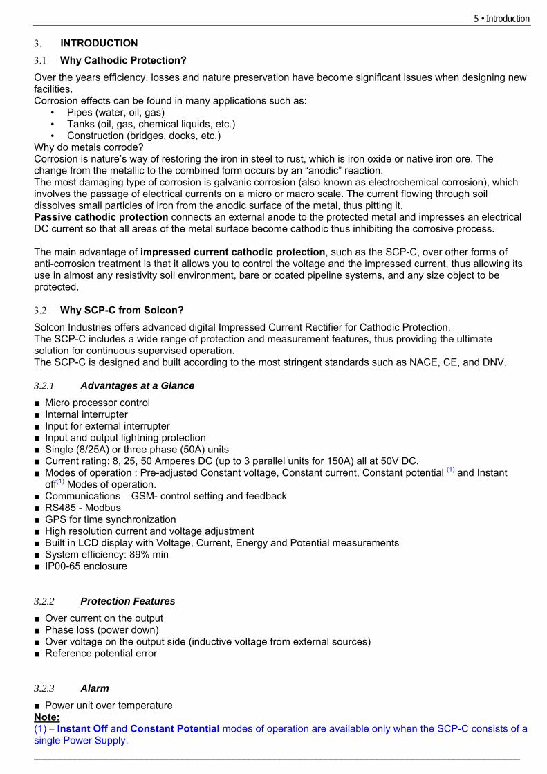
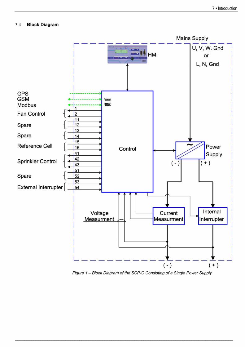
3.4 Block Diagram
Figure 1 – Block Diagram of the SCP-C Consisting of a Single Power Supply
8 • Introduction
________________________________________________________________________________________________
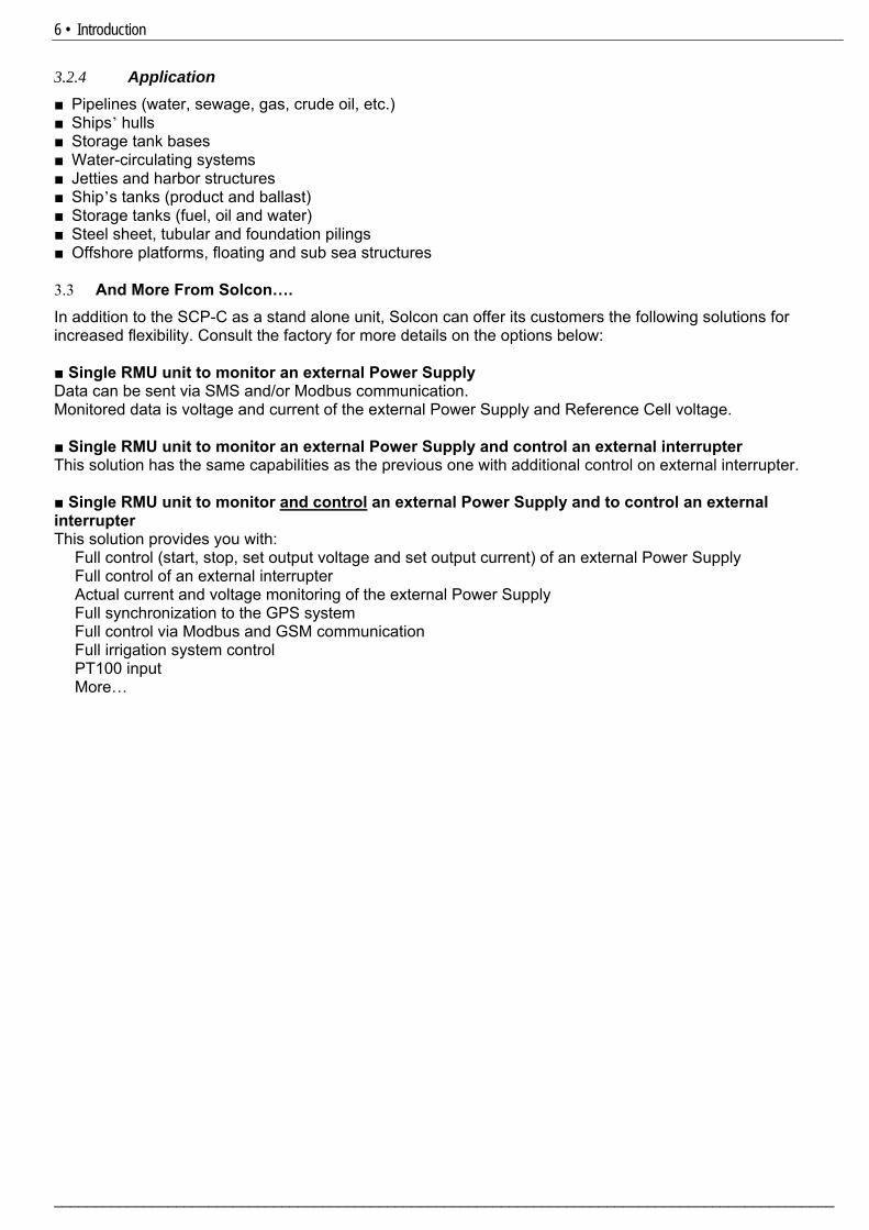
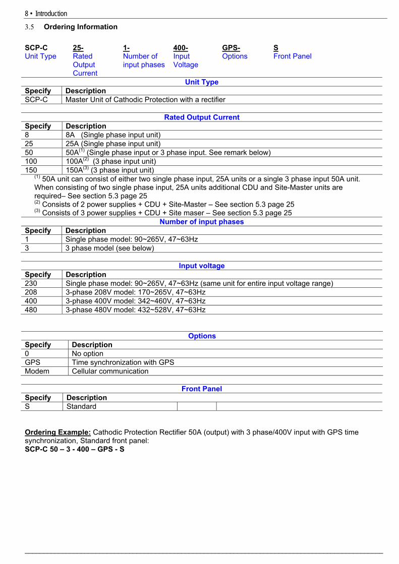
3.5 Ordering Information SCP-C 25- 1- 400- GPS- S Unit Type Rated
Output Current
Number of input phases
Input Voltage
Options Front Panel
Unit Type Specify Description SCP-C Master Unit of Cathodic Protection with a rectifier
Rated Output Current Specify Description 8 8A (Single phase input unit) 25 25A (Single phase input unit) 50 50A(1) (Single phase input or 3 phase input. See remark below) 100 100A(2) (3 phase input unit) 150 150A(3) (3 phase input unit)
(1) 50A unit can consist of either two single phase input, 25A units or a single 3 phase input 50A unit. When consisting of two single phase input, 25A units additional CDU and Site-Master units are required– See section 5.3 page 25 (2) Consists of 2 power supplies + CDU + Site-Master – See section 5.3 page 25 (3) Consists of 3 power supplies + CDU + Site maser – See section 5.3 page 25
Number of input phases Specify Description 1 Single phase model: 90~265V, 47~63Hz 3 3 phase model (see below)
Input voltage Specify Description 230 Single phase model: 90~265V, 47~63Hz (same unit for entire input voltage range) 208 3-phase 208V model: 170~265V, 47~63Hz 400 3-phase 400V model: 342~460V, 47~63Hz 480 3-phase 480V model: 432~528V, 47~63Hz
Options Specify Description 0 No option GPS Time synchronization with GPS Modem Cellular communication
Front Panel Specify Description S Standard Ordering Example: Cathodic Protection Rectifier 50A (output) with 3 phase/400V input with GPS time synchronization, Standard front panel: SCP-C 50 – 3 - 400 – GPS - S
9 • Technical Data
_______________________________________________________________________________________________
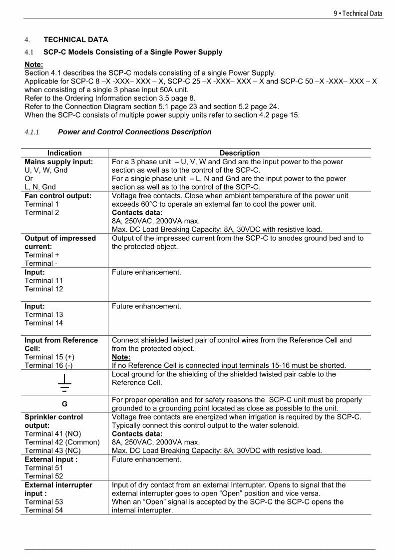
4. TECHNICAL DATA 4.1 SCP-C Models Consisting of a Single Power Supply Note: Section 4.1 describes the SCP-C models consisting of a single Power Supply. Applicable for SCP-C 8 –X -XXX– XXX – X, SCP-C 25 –X -XXX– XXX – X and SCP-C 50 –X -XXX– XXX – X when consisting of a single 3 phase input 50A unit. Refer to the Ordering Information section 3.5 page 8. Refer to the Connection Diagram section 5.1 page 23 and section 5.2 page 24. When the SCP-C consists of multiple power supply units refer to section 4.2 page 15. 4.1.1 Power and Control Connections Description
Indication Description Mains supply input: U, V, W, Gnd Or L, N, Gnd
For a 3 phase unit – U, V, W and Gnd are the input power to the power section as well as to the control of the SCP-C. For a single phase unit – L, N and Gnd are the input power to the power section as well as to the control of the SCP-C.
Fan control output: Terminal 1 Terminal 2
Voltage free contacts. Close when ambient temperature of the power unit exceeds 60°C to operate an external fan to cool the power unit. Contacts data: 8A, 250VAC, 2000VA max. Max. DC Load Breaking Capacity: 8A, 30VDC with resistive load.
Output of impressed current: Terminal + Terminal -
Output of the impressed current from the SCP-C to anodes ground bed and to the protected object.
Input: Terminal 11 Terminal 12
Future enhancement.
Input: Terminal 13 Terminal 14
Future enhancement.
Input from Reference Cell: Terminal 15 (+) Terminal 16 (-)
Connect shielded twisted pair of control wires from the Reference Cell and from the protected object. Note: If no Reference Cell is connected input terminals 15-16 must be shorted.
Local ground for the shielding of the shielded twisted pair cable to the Reference Cell.
G For proper operation and for safety reasons the SCP-C unit must be properly grounded to a grounding point located as close as possible to the unit.
Sprinkler control output: Terminal 41 (NO) Terminal 42 (Common) Terminal 43 (NC)
Voltage free contacts are energized when irrigation is required by the SCP-C. Typically connect this control output to the water solenoid. Contacts data: 8A, 250VAC, 2000VA max. Max. DC Load Breaking Capacity: 8A, 30VDC with resistive load.
External input : Terminal 51 Terminal 52
Future enhancement.
External interrupter input : Terminal 53 Terminal 54
Input of dry contact from an external Interrupter. Opens to signal that the external interrupter goes to open “Open” position and vice versa. When an “Open” signal is accepted by the SCP-C the SCP-C opens the internal interrupter.
10 • Technical Data
________________________________________________________________________________________________
Indication Description
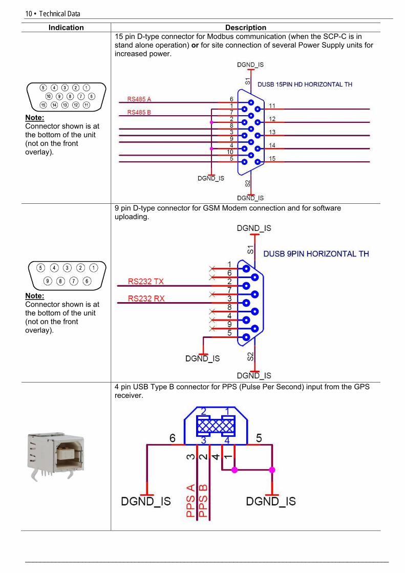
Note: Connector shown is at the bottom of the unit (not on the front overlay).
15 pin D-type connector for Modbus communication (when the SCP-C is in stand alone operation) or for site connection of several Power Supply units for increased power.
Note: Connector shown is at the bottom of the unit (not on the front overlay).
9 pin D-type connector for GSM Modem connection and for software uploading.
4 pin USB Type B connector for PPS (Pulse Per Second) input from the GPS receiver.
11 • Technical Data
_______________________________________________________________________________________________
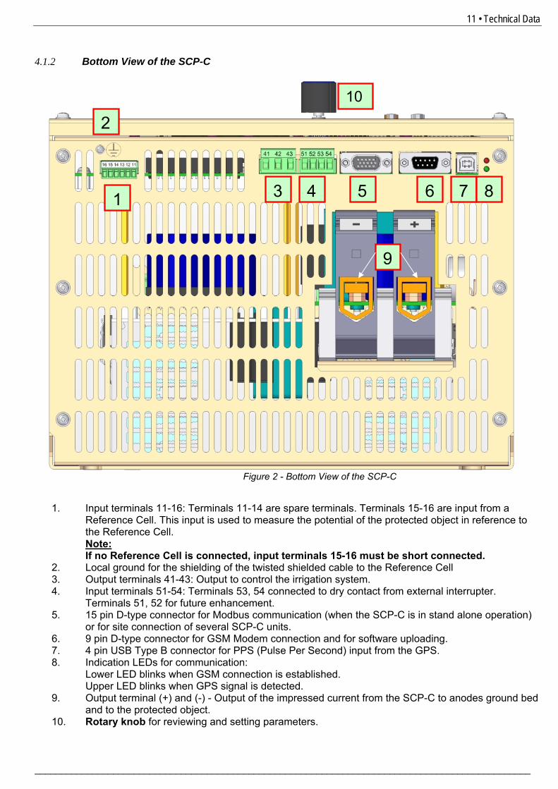
4.1.2 Bottom View of the SCP-C
1. Input terminals 11-16: Terminals 11-14 are spare terminals. Terminals 15-16 are input from a
Reference Cell. This input is used to measure the potential of the protected object in reference to the Reference Cell. Note: If no Reference Cell is connected, input terminals 15-16 must be short connected.
2. Local ground for the shielding of the twisted shielded cable to the Reference Cell 3. Output terminals 41-43: Output to control the irrigation system. 4. Input terminals 51-54: Terminals 53, 54 connected to dry contact from external interrupter.
Terminals 51, 52 for future enhancement. 5. 15 pin D-type connector for Modbus communication (when the SCP-C is in stand alone operation)
or for site connection of several SCP-C units. 6. 9 pin D-type connector for GSM Modem connection and for software uploading. 7. 4 pin USB Type B connector for PPS (Pulse Per Second) input from the GPS. 8. Indication LEDs for communication:
Lower LED blinks when GSM connection is established. Upper LED blinks when GPS signal is detected.
9. Output terminal (+) and (-) - Output of the impressed current from the SCP-C to anodes ground bed and to the protected object.
10. Rotary knob for reviewing and setting parameters.
Figure 2 - Bottom View of the SCP-C
1
2
543 6 7 8
9
10
12 • Technical Data
________________________________________________________________________________________________
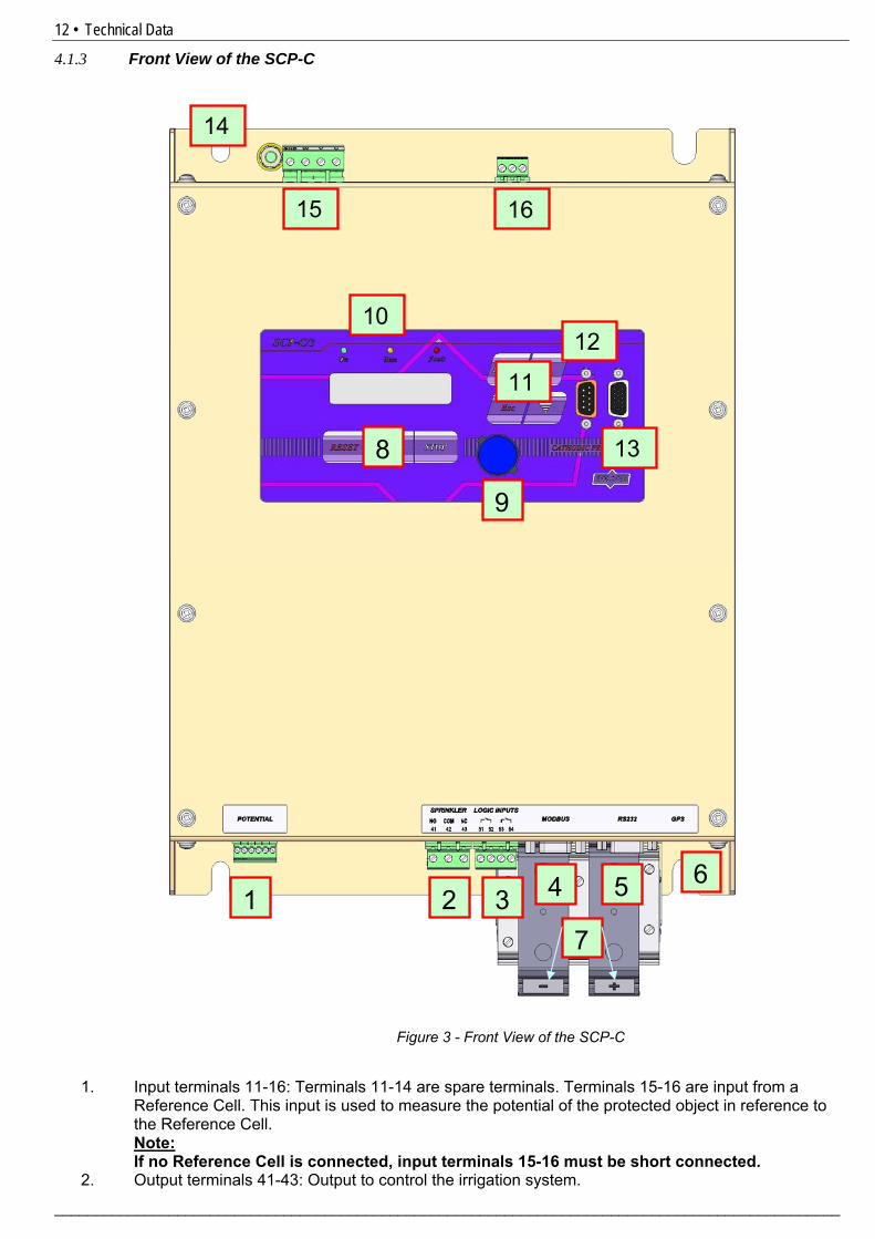
4.1.3 Front View of the SCP-C
1. Input terminals 11-16: Terminals 11-14 are spare terminals. Terminals 15-16 are input from a
Reference Cell. This input is used to measure the potential of the protected object in reference to the Reference Cell. Note: If no Reference Cell is connected, input terminals 15-16 must be short connected.
2. Output terminals 41-43: Output to control the irrigation system.
Figure 3 - Front View of the SCP-C
8
7
10
21 3 4 5 6
9
1615
14
11
12
13
13 • Technical Data
_______________________________________________________________________________________________
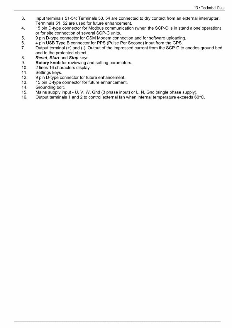
3. Input terminals 51-54: Terminals 53, 54 are connected to dry contact from an external interrupter. Terminals 51, 52 are used for future enhancement.
4. 15 pin D-type connector for Modbus communication (when the SCP-C is in stand alone operation) or for site connection of several SCP-C units.
5. 9 pin D-type connector for GSM Modem connection and for software uploading. 6. 4 pin USB Type B connector for PPS (Pulse Per Second) input from the GPS. 7. Output terminal (+) and (-): Output of the impressed current from the SCP-C to anodes ground bed
and to the protected object. 8. Reset, Start and Stop keys. 9. Rotary knob for reviewing and setting parameters. 10. 2 lines 16 characters display. 11. Settings keys. 12. 9 pin D-type connector for future enhancement. 13. 15 pin D-type connector for future enhancement. 14. Grounding bolt. 15. Mains supply input - U, V, W, Gnd (3 phase input) or L, N, Gnd (single phase supply). 16. Output terminals 1 and 2 to control external fan when internal temperature exceeds 60°C.
14 • Technical Data
________________________________________________________________________________________________
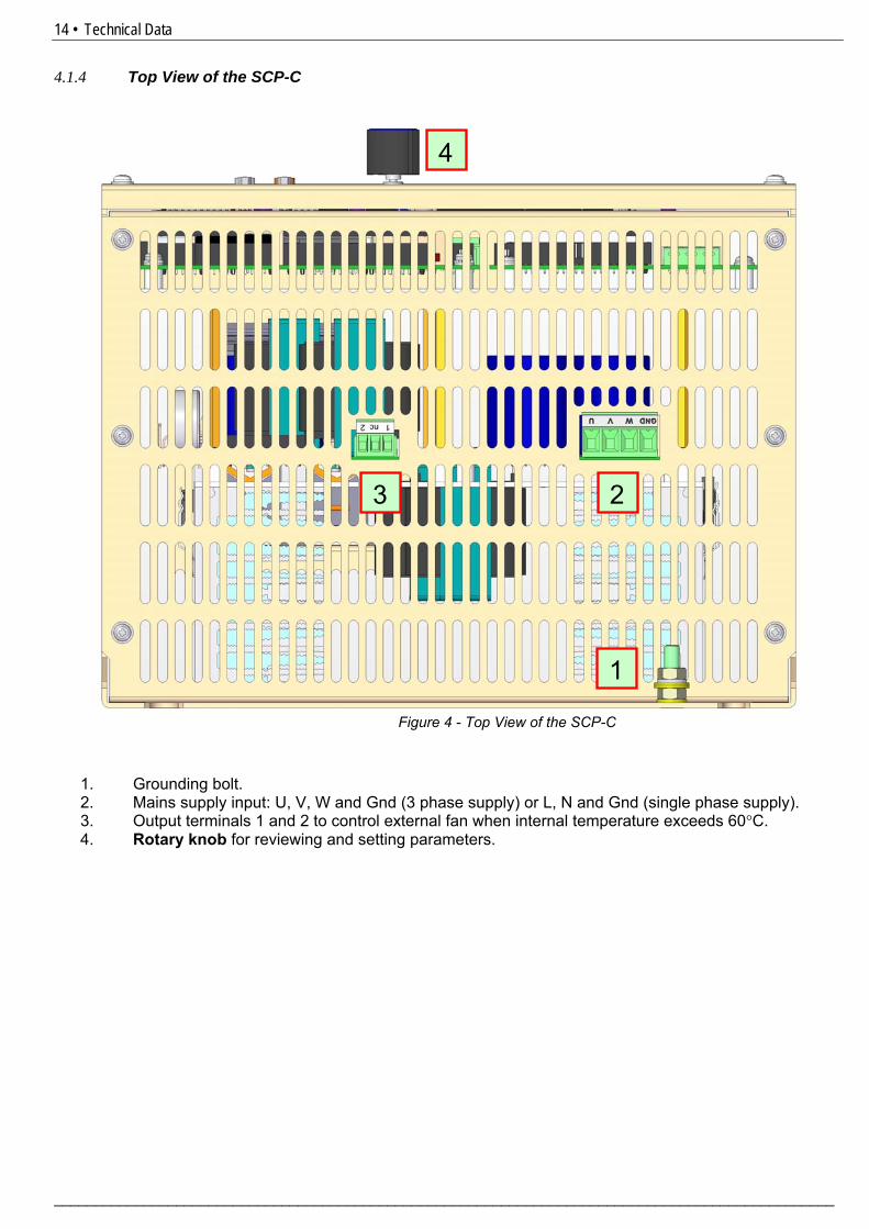
4.1.4 Top View of the SCP-C
1. Grounding bolt. 2. Mains supply input: U, V, W and Gnd (3 phase supply) or L, N and Gnd (single phase supply). 3. Output terminals 1 and 2 to control external fan when internal temperature exceeds 60°C. 4. Rotary knob for reviewing and setting parameters.
Figure 4 - Top View of the SCP-C
1
2 3
4
15 • Technical Data
_______________________________________________________________________________________________
4.2 SCP-C Models Consisting of Multiple Power Supply Units Note: Section 4.2 describes the SCP-C models consisting of multiple Power Supply units. Applicable for SCP-C 150 –X -XXX– XXX – X, SCP-C 100 –X -XXX– XXX – X and SCP-C 50 –X -XXX– XXX – X when consists of two single phase input 25A units. Refer to the Ordering Information section 3.5 page 8. Refer to the Connection Diagram section 5.1 page 23 and section 5.2 page 24. When the SCP-C consists of a single Power Supply refer to section 4.1 page 9. 4.2.1 Site-Master Control wiring
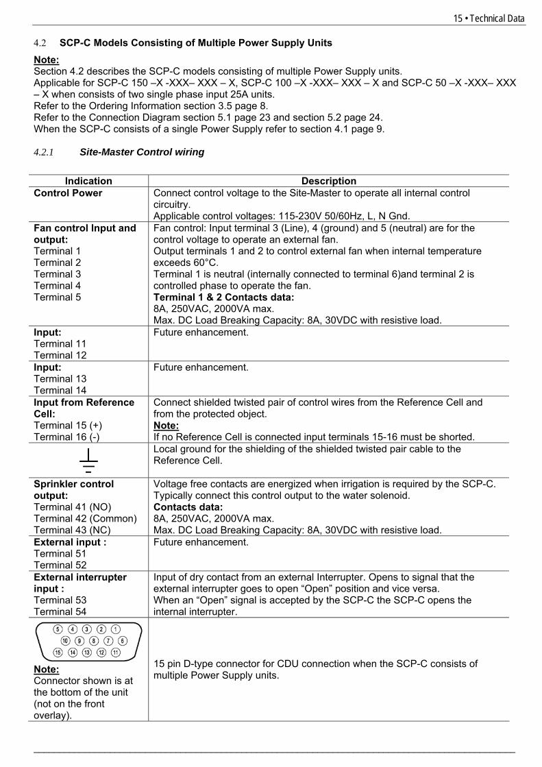
Indication Description Control Power Connect control voltage to the Site-Master to operate all internal control
circuitry. Applicable control voltages: 115-230V 50/60Hz, L, N Gnd.
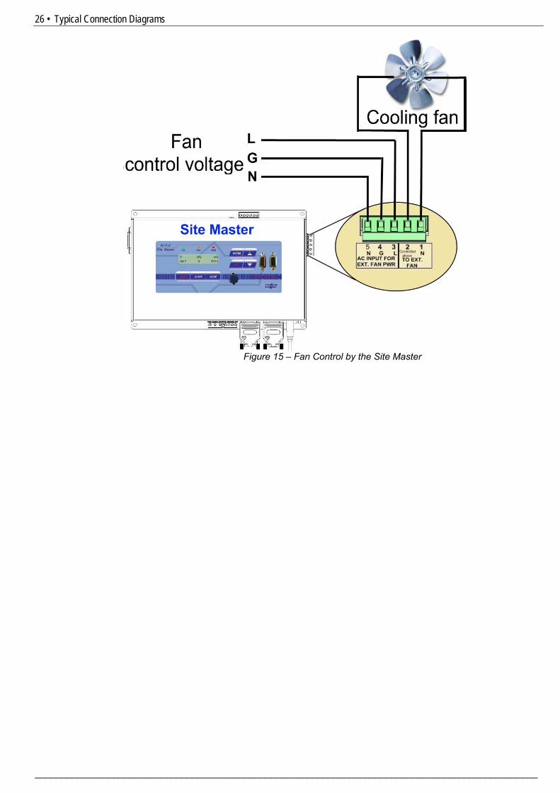
Fan control Input and output: Terminal 1 Terminal 2 Terminal 3 Terminal 4 Terminal 5
Fan control: Input terminal 3 (Line), 4 (ground) and 5 (neutral) are for the control voltage to operate an external fan. Output terminals 1 and 2 to control external fan when internal temperature exceeds 60°C. Terminal 1 is neutral (internally connected to terminal 6)and terminal 2 is controlled phase to operate the fan. Terminal 1 & 2 Contacts data: 8A, 250VAC, 2000VA max. Max. DC Load Breaking Capacity: 8A, 30VDC with resistive load.
Input: Terminal 11 Terminal 12
Future enhancement.
Input: Terminal 13 Terminal 14
Future enhancement.
Input from Reference Cell: Terminal 15 (+) Terminal 16 (-)
Connect shielded twisted pair of control wires from the Reference Cell and from the protected object. Note: If no Reference Cell is connected input terminals 15-16 must be shorted.
Local ground for the shielding of the shielded twisted pair cable to the Reference Cell.
Sprinkler control output: Terminal 41 (NO) Terminal 42 (Common) Terminal 43 (NC)
Voltage free contacts are energized when irrigation is required by the SCP-C. Typically connect this control output to the water solenoid. Contacts data: 8A, 250VAC, 2000VA max. Max. DC Load Breaking Capacity: 8A, 30VDC with resistive load.
External input : Terminal 51 Terminal 52
Future enhancement.
External interrupter input : Terminal 53 Terminal 54
Input of dry contact from an external Interrupter. Opens to signal that the external interrupter goes to open “Open” position and vice versa. When an “Open” signal is accepted by the SCP-C the SCP-C opens the internal interrupter.
Note: Connector shown is at the bottom of the unit (not on the front overlay).
15 pin D-type connector for CDU connection when the SCP-C consists of multiple Power Supply units.
16 • Technical Data
________________________________________________________________________________________________
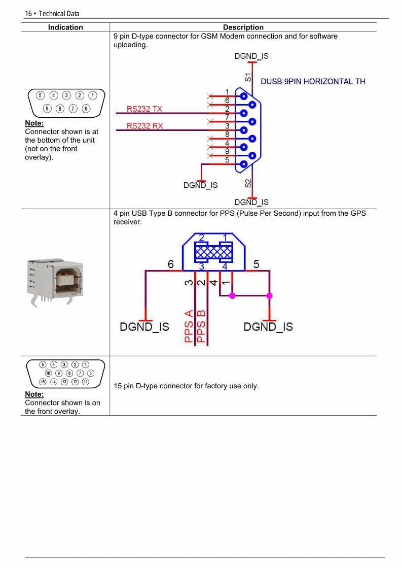
Indication Description
Note: Connector shown is at the bottom of the unit (not on the front overlay).
9 pin D-type connector for GSM Modem connection and for software uploading.
4 pin USB Type B connector for PPS (Pulse Per Second) input from the GPS receiver.
Note: Connector shown is on the front overlay.
15 pin D-type connector for factory use only.
17 • Technical Data
_______________________________________________________________________________________________
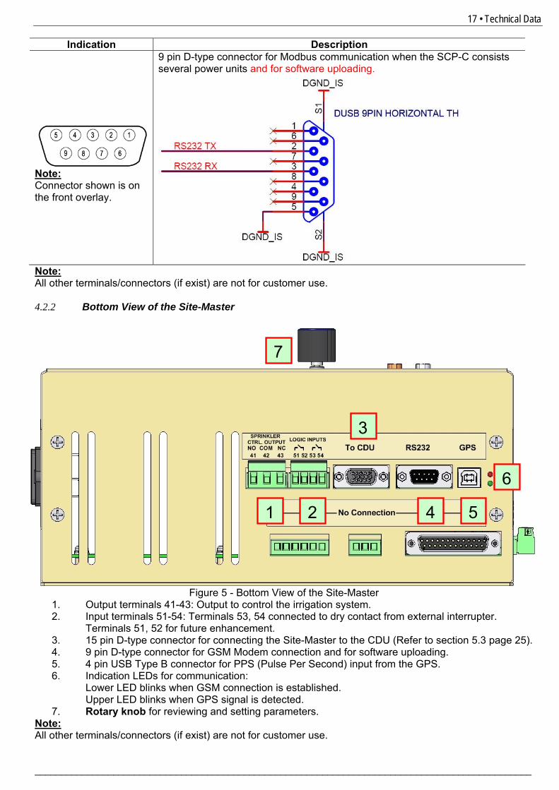
Indication Description
Note: Connector shown is on the front overlay.
9 pin D-type connector for Modbus communication when the SCP-C consists several power units and for software uploading.
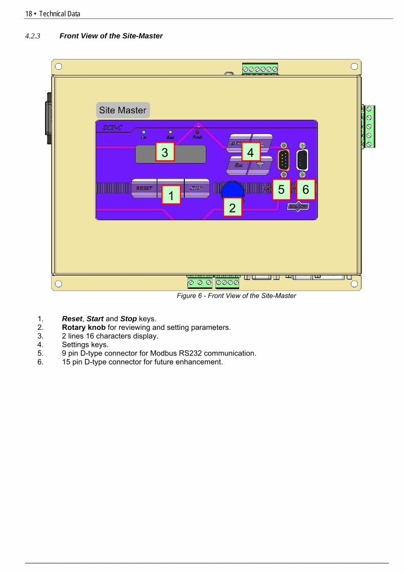
Note: All other terminals/connectors (if exist) are not for customer use. 4.2.2 Bottom View of the Site-Master
1. Output terminals 41-43: Output to control the irrigation system. 2. Input terminals 51-54: Terminals 53, 54 connected to dry contact from external interrupter.
Terminals 51, 52 for future enhancement. 3. 15 pin D-type connector for connecting the Site-Master to the CDU (Refer to section 5.3 page 25). 4. 9 pin D-type connector for GSM Modem connection and for software uploading. 5. 4 pin USB Type B connector for PPS (Pulse Per Second) input from the GPS. 6. Indication LEDs for communication:
Lower LED blinks when GSM connection is established. Upper LED blinks when GPS signal is detected.
7. Rotary knob for reviewing and setting parameters. Note: All other terminals/connectors (if exist) are not for customer use.
Figure 5 - Bottom View of the Site-Master
3
21 4 5
6
7
18 • Technical Data
________________________________________________________________________________________________
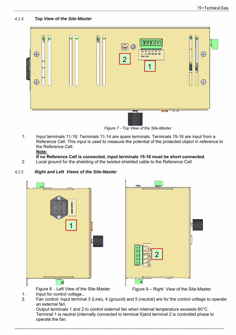
4.2.3 Front View of the Site-Master
1. Reset, Start and Stop keys. 2. Rotary knob for reviewing and setting parameters. 3. 2 lines 16 characters display. 4. Settings keys. 5. 9 pin D-type connector for Modbus RS232 communication. 6. 15 pin D-type connector for future enhancement.
Figure 6 - Front View of the Site-Master
12
3 4
5 6
19 • Technical Data
_______________________________________________________________________________________________
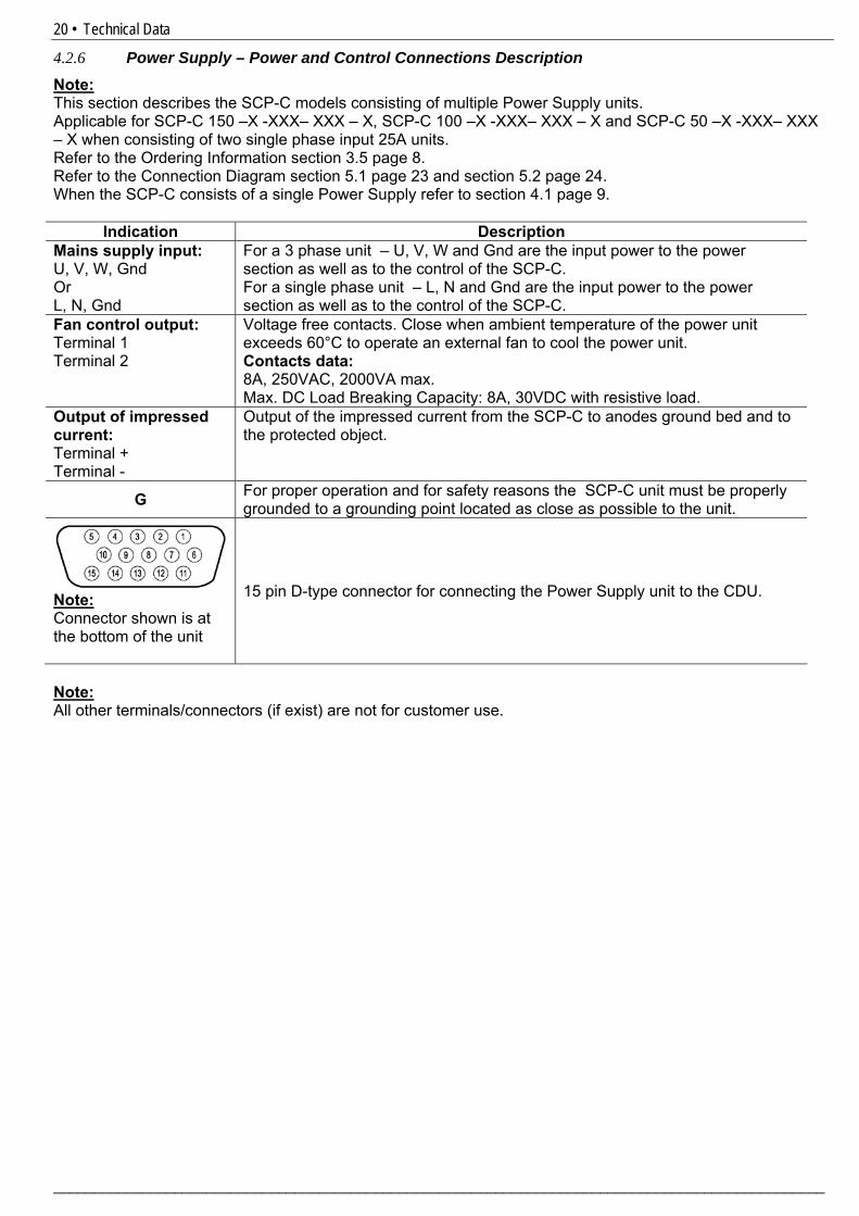
4.2.4 Top View of the Site-Master
1. Input terminals 11-16: Terminals 11-14 are spare terminals. Terminals 15-16 are input from a Reference Cell. This input is used to measure the potential of the protected object in reference to the Reference Cell. Note: If no Reference Cell is connected, input terminals 15-16 must be short connected.
2. Local ground for the shielding of the twisted shielded cable to the Reference Cell
4.2.5 Right and Left Views of the Site-Master
1. Input for control voltage.. 2. Fan control: Input terminal 3 (Line), 4 (ground) and 5 (neutral) are for the control voltage to operate
an external fan. Output terminals 1 and 2 to control external fan when internal temperature exceeds 60°C. Terminal 1 is neutral (internally connected to terminal 6)and terminal 2 is controlled phase to operate the fan.
Figure 7 - Top View of the Site-Master
Figure 8 – Left View of the Site-Master
Figure 9 – Right View of the Site-Master
12
1
2
20 • Technical Data
________________________________________________________________________________________________
4.2.6 Power Supply – Power and Control Connections Description Note: This section describes the SCP-C models consisting of multiple Power Supply units. Applicable for SCP-C 150 –X -XXX– XXX – X, SCP-C 100 –X -XXX– XXX – X and SCP-C 50 –X -XXX– XXX – X when consisting of two single phase input 25A units. Refer to the Ordering Information section 3.5 page 8. Refer to the Connection Diagram section 5.1 page 23 and section 5.2 page 24. When the SCP-C consists of a single Power Supply refer to section 4.1 page 9.
Indication Description Mains supply input: U, V, W, Gnd Or L, N, Gnd
For a 3 phase unit – U, V, W and Gnd are the input power to the power section as well as to the control of the SCP-C. For a single phase unit – L, N and Gnd are the input power to the power section as well as to the control of the SCP-C.
Fan control output: Terminal 1 Terminal 2
Voltage free contacts. Close when ambient temperature of the power unit exceeds 60°C to operate an external fan to cool the power unit. Contacts data: 8A, 250VAC, 2000VA max. Max. DC Load Breaking Capacity: 8A, 30VDC with resistive load.
Output of impressed current: Terminal + Terminal -
Output of the impressed current from the SCP-C to anodes ground bed and to the protected object.
G For proper operation and for safety reasons the SCP-C unit must be properly grounded to a grounding point located as close as possible to the unit.
Note: Connector shown is at the bottom of the unit
15 pin D-type connector for connecting the Power Supply unit to the CDU.
Note: All other terminals/connectors (if exist) are not for customer use.
21 • Technical Data
_______________________________________________________________________________________________
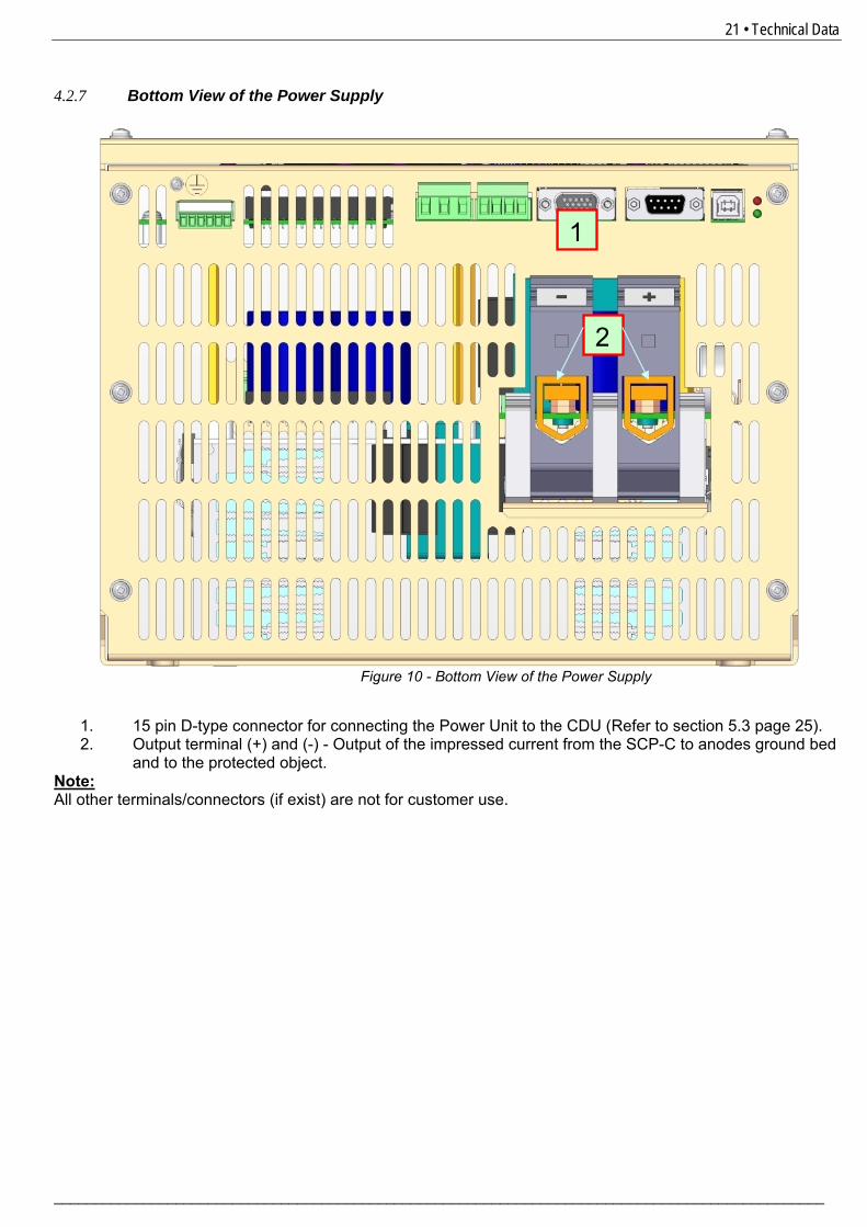
4.2.7 Bottom View of the Power Supply
1. 15 pin D-type connector for connecting the Power Unit to the CDU (Refer to section 5.3 page 25). 2. Output terminal (+) and (-) - Output of the impressed current from the SCP-C to anodes ground bed
and to the protected object. Note: All other terminals/connectors (if exist) are not for customer use.
Figure 10 - Bottom View of the Power Supply
2
1
22 • Technical Data
________________________________________________________________________________________________
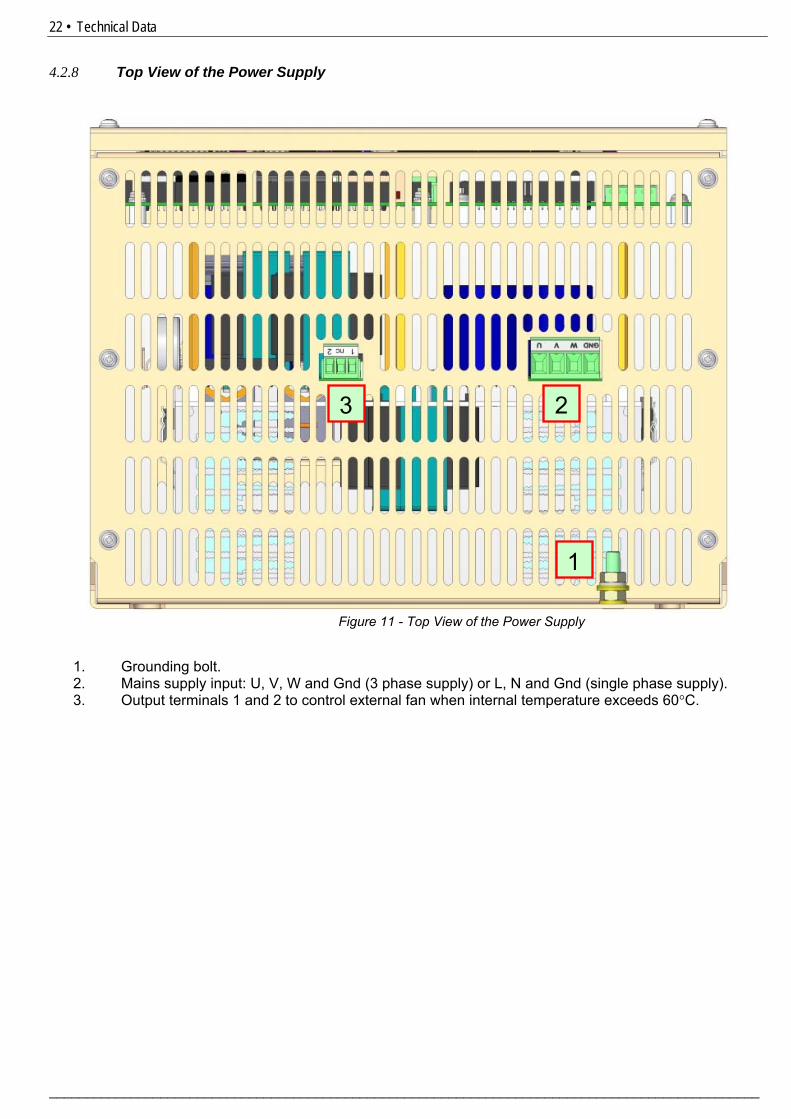
4.2.8 Top View of the Power Supply
1. Grounding bolt. 2. Mains supply input: U, V, W and Gnd (3 phase supply) or L, N and Gnd (single phase supply). 3. Output terminals 1 and 2 to control external fan when internal temperature exceeds 60°C.
Figure 11 - Top View of the Power Supply
1
2 3
23 • Typical Connection Diagrams
_______________________________________________________________________________________________
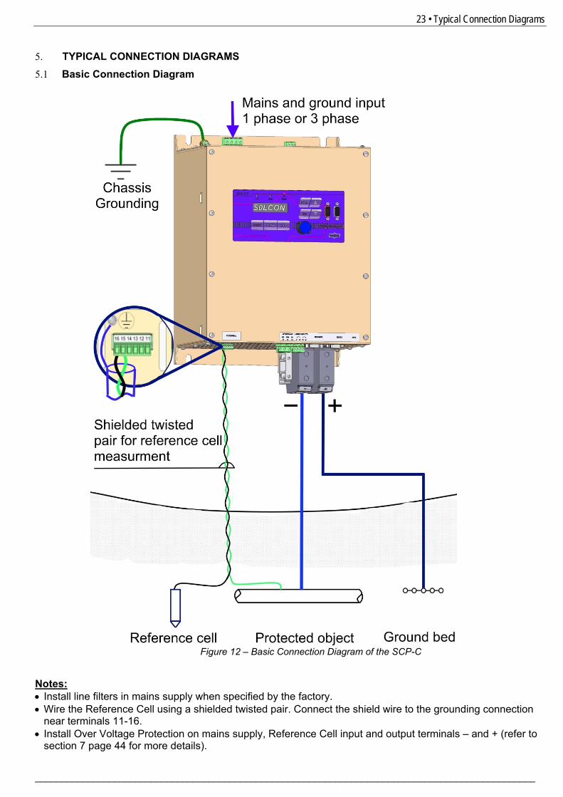
5. TYPICAL CONNECTION DIAGRAMS 5.1 Basic Connection Diagram
Notes: • Install line filters in mains supply when specified by the factory. • Wire the Reference Cell using a shielded twisted pair. Connect the shield wire to the grounding connection
near terminals 11-16. • Install Over Voltage Protection on mains supply, Reference Cell input and output terminals – and + (refer to
section 1 7 page 144 for more details).
Figure 12 – Basic Connection Diagram of the SCP-C
24 • Typical Connection Diagrams
________________________________________________________________________________________________
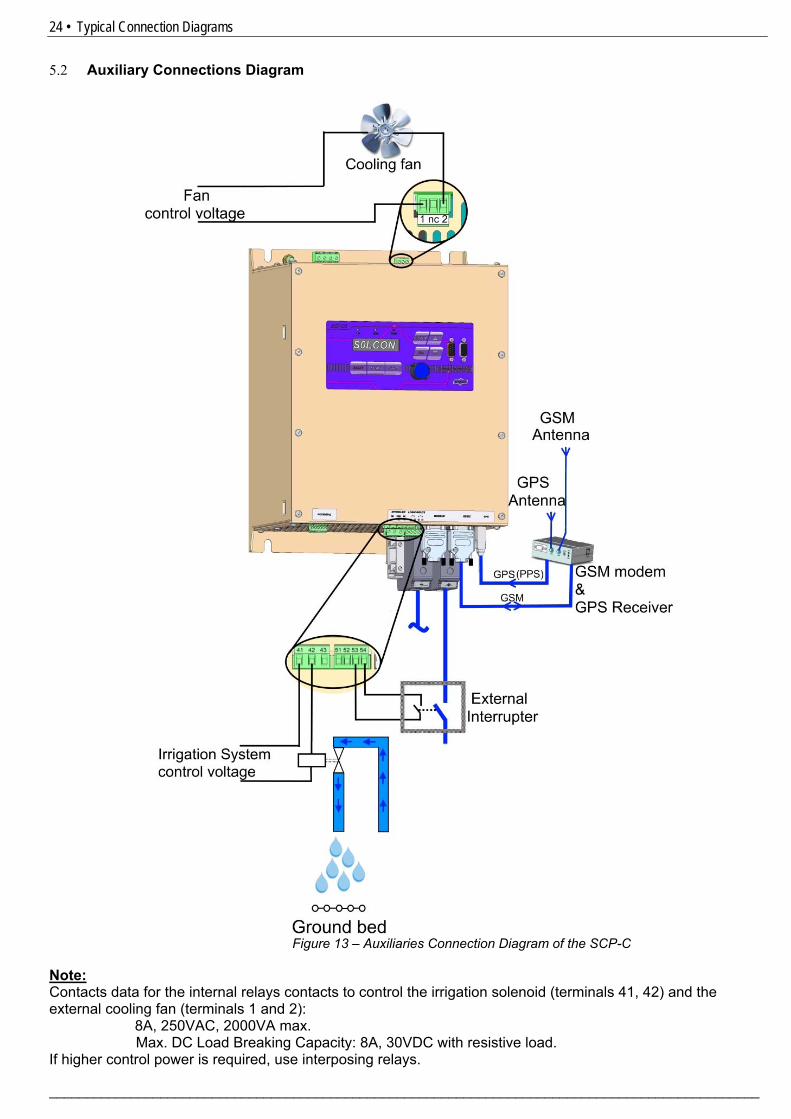
5.2 Auxiliary Connections Diagram
Note: Contacts data for the internal relays contacts to control the irrigation solenoid (terminals 41, 42) and the external cooling fan (terminals 1 and 2):
8A, 250VAC, 2000VA max. Max. DC Load Breaking Capacity: 8A, 30VDC with resistive load.
If higher control power is required, use interposing relays.
Figure 13 – Auxiliaries Connection Diagram of the SCP-C

25 • Typical Connection Diagrams
_______________________________________________________________________________________________
5.3 SCP-C Models Consisting of Multiple Power Supply Units
Notes: • Connection of up to 3 Power Supply units in parallel requires additional equipment: CDU unit and Site-
Master unit. • The Power Supply units shown in Figure 14 are modified SCP-C stand alone units. • Power Supply cooling fans can be connected as shown in Figure 13 page 24. • Additional fan control can be connected to the Site-Master as indicated in Figure 15 page 26. • Irrigation system control, GSM Modem & GPS Receiver, are connected to the Site-Master.
Terminals/connectors indications (Terminals numbers etc.) are the same as of the SCP-C unit as shown in Figure 13 page 24.
Figure 14 – SCP-C models consisting of multiple Power Supply units
26 • Typical Connection Diagrams
________________________________________________________________________________________________
Figure 15 – Fan Control by the Site Master
27 • Control Keypad
_______________________________________________________________________________________________
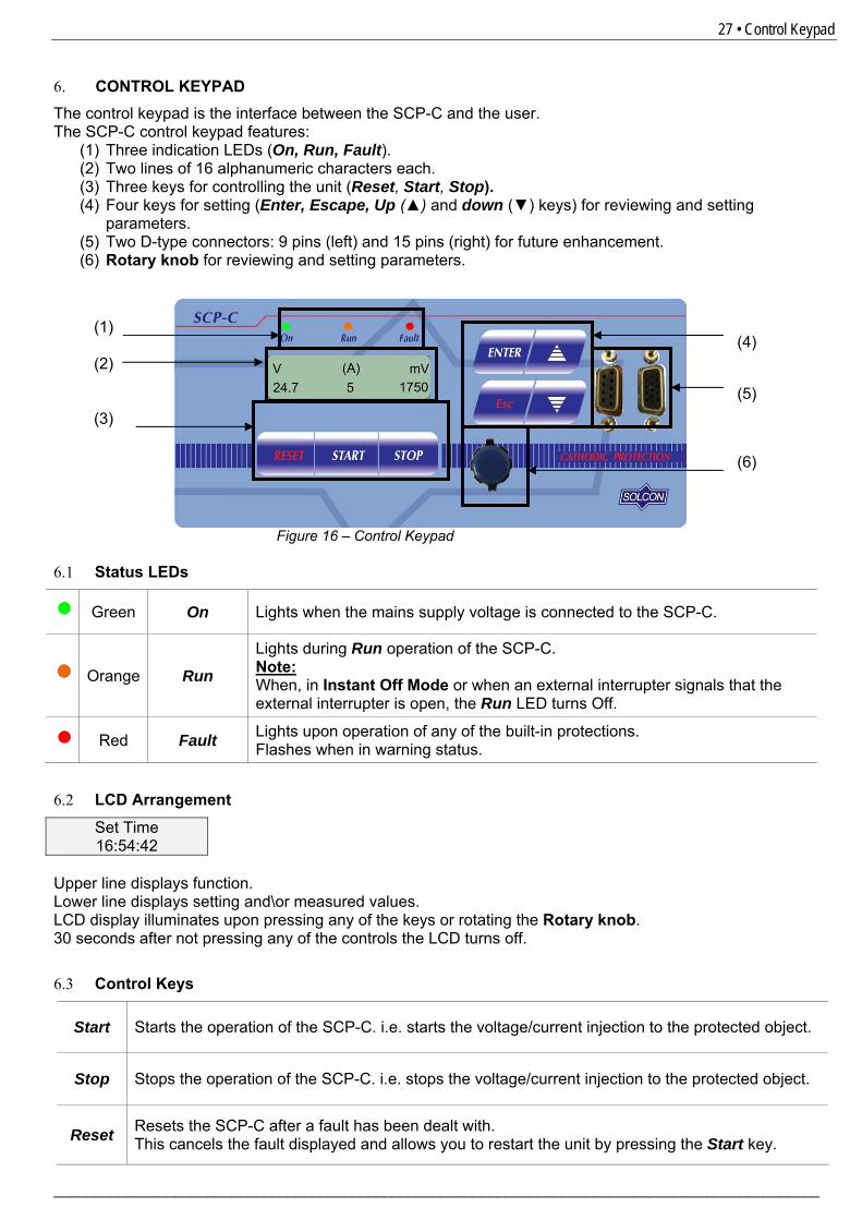
6. CONTROL KEYPAD The control keypad is the interface between the SCP-C and the user. The SCP-C control keypad features:
(1) Three indication LEDs (On, Run, Fault). (2) Two lines of 16 alphanumeric characters each. (3) Three keys for controlling the unit (Reset, Start, Stop). (4) Four keys for setting (Enter, Escape, Up (▲) and down (▼) keys) for reviewing and setting
parameters. (5) Two D-type connectors: 9 pins (left) and 15 pins (right) for future enhancement. (6) Rotary knob for reviewing and setting parameters.
6.1 Status LEDs
Green On Lights when the mains supply voltage is connected to the SCP-C.
Orange Run Lights during Run operation of the SCP-C. Note: When, in Instant Off Mode or when an external interrupter signals that the external interrupter is open, the Run LED turns Off.
Red Fault Lights upon operation of any of the built-in protections.
Flashes when in warning status. 6.2 LCD Arrangement
Set Time 16:54:42
Upper line displays function. Lower line displays setting and\or measured values. LCD display illuminates upon pressing any of the keys or rotating the Rotary knob. 30 seconds after not pressing any of the controls the LCD turns off. 6.3 Control Keys
Start Starts the operation of the SCP-C. i.e. starts the voltage/current injection to the protected object.
Stop Stops the operation of the SCP-C. i.e. stops the voltage/current injection to the protected object.
Reset Resets the SCP-C after a fault has been dealt with. This cancels the fault displayed and allows you to restart the unit by pressing the Start key.
(1) (2) (3)
Figure 16 – Control Keypad
(4)
(5)
(6)
28 • Control Keypad
________________________________________________________________________________________________
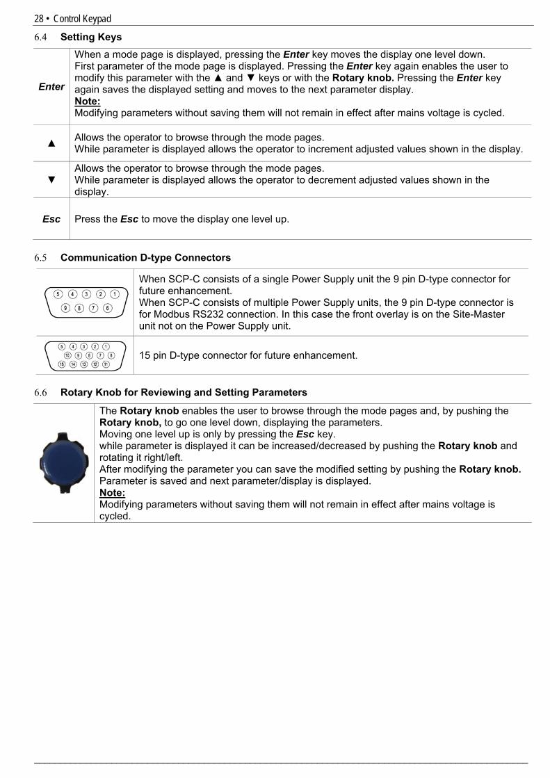
6.4 Setting Keys
Enter
When a mode page is displayed, pressing the Enter key moves the display one level down. First parameter of the mode page is displayed. Pressing the Enter key again enables the user to modify this parameter with the ▲ and ▼ keys or with the Rotary knob. Pressing the Enter key again saves the displayed setting and moves to the next parameter display. Note: Modifying parameters without saving them will not remain in effect after mains voltage is cycled.
▲ Allows the operator to browse through the mode pages. While parameter is displayed allows the operator to increment adjusted values shown in the display.
▼ Allows the operator to browse through the mode pages. While parameter is displayed allows the operator to decrement adjusted values shown in the display.
Esc Press the Esc to move the display one level up.
6.5 Communication D-type Connectors
When SCP-C consists of a single Power Supply unit the 9 pin D-type connector for future enhancement. When SCP-C consists of multiple Power Supply units, the 9 pin D-type connector is for Modbus RS232 connection. In this case the front overlay is on the Site-Master unit not on the Power Supply unit.
15 pin D-type connector for future enhancement.
6.6 Rotary Knob for Reviewing and Setting Parameters
The Rotary knob enables the user to browse through the mode pages and, by pushing the Rotary knob, to go one level down, displaying the parameters. Moving one level up is only by pressing the Esc key. while parameter is displayed it can be increased/decreased by pushing the Rotary knob and rotating it right/left. After modifying the parameter you can save the modified setting by pushing the Rotary knob. Parameter is saved and next parameter/display is displayed. Note: Modifying parameters without saving them will not remain in effect after mains voltage is cycled.
29 • Control Keypad
_______________________________________________________________________________________________
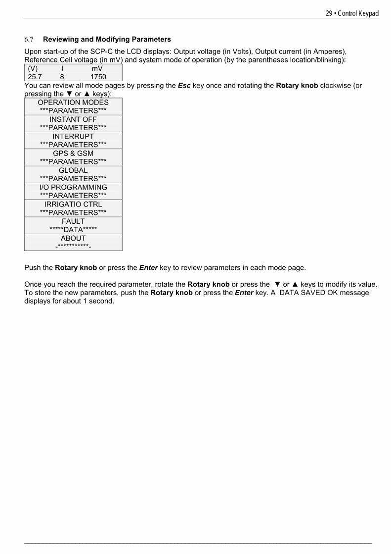
6.7 Reviewing and Modifying Parameters Upon start-up of the SCP-C the LCD displays: Output voltage (in Volts), Output current (in Amperes), Reference Cell voltage (in mV) and system mode of operation (by the parentheses location/blinking): (V) I mV 25.7 8 1750
You can review all mode pages by pressing the Esc key once and rotating the Rotary knob clockwise (or pressing the ▼ or ▲ keys):
Push the Rotary knob or press the Enter key to review parameters in each mode page. Once you reach the required parameter, rotate the Rotary knob or press the ▼ or ▲ keys to modify its value. To store the new parameters, push the Rotary knob or press the Enter key. A DATA SAVED OK message displays for about 1 second.
OPERATION MODES ***PARAMETERS***
INSTANT OFF ***PARAMETERS***
INTERRUPT ***PARAMETERS***
GPS & GSM ***PARAMETERS***
GLOBAL ***PARAMETERS*** I/O PROGRAMMING ***PARAMETERS***
IRRIGATIO CTRL ***PARAMETERS***
FAULT *****DATA*****
ABOUT -***********-
30 • Control Keypad
________________________________________________________________________________________________
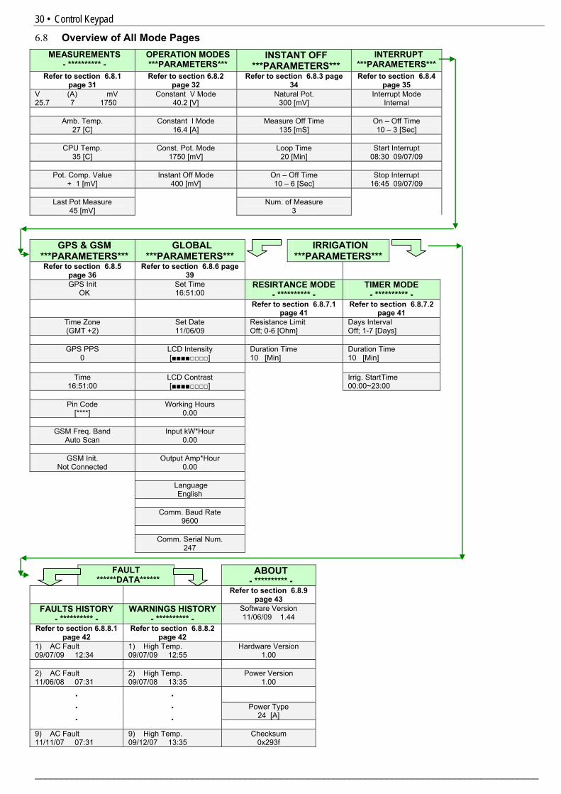
6.8 Overview of All Mode Pages MEASUREMENTS
- ********** - OPERATION MODES ***PARAMETERS***
INSTANT OFF ***PARAMETERS***
INTERRUPT ***PARAMETERS***
Refer to section 1 6.8.1 page 131
Refer to section 1 6.8.2 page 132
Refer to section 1 6.8.3 page 134
Refer to section 1 6.8.4 page 135
V (A) mV 25.7 7 1750
Constant V Mode 40.2 [V]
Natural Pot. 300 [mV]
Interrupt Mode Internal
Amb. Temp.
27 [C] Constant I Mode
16.4 [A] Measure Off Time
135 [mS] On – Off Time 10 – 3 [Sec]
CPU Temp.
35 [C] Const. Pot. Mode
1750 [mV] Loop Time
20 [Min] Start Interrupt
08:30 09/07/09
Pot. Comp. Value + 1 [mV]
Instant Off Mode 400 [mV]
On – Off Time 10 – 6 [Sec]
Stop Interrupt 16:45 09/07/09
Last Pot Measure
45 [mV] Num. of Measure
3
GPS & GSM ***PARAMETERS***
GLOBAL ***PARAMETERS***
IRRIGATION ***PARAMETERS***
Refer to section 1 6.8.5 page 136
Refer to section 1 6.8.6 page 139
GPS Init OK
Set Time 16:51:00
RESIRTANCE MODE - ********** -
TIMER MODE - ********** -
Refer to section 1 6.8.7.1 page 141
Refer to section 1 6.8.7.2 page 141
Time Zone (GMT +2)
Set Date 11/06/09
Resistance Limit Off; 0-6 [Ohm]
Days Interval Off; 1-7 [Days]
GPS PPS
0 LCD Intensity [■■■■□□□□]
Duration Time 10 [Min]
Duration Time 10 [Min]
Time
16:51:00 LCD Contrast [■■■■□□□□]
Irrig. StartTime 00:00~23:00
Pin Code
[****] Working Hours
0.00
GSM Freq. Band
Auto Scan Input kW*Hour
0.00
GSM Init. Not Connected
Output Amp*Hour 0.00
Language
English
Comm. Baud Rate 9600
Comm. Serial Num.
247
FAULT ******DATA******
ABOUT - ********** -
Refer to section 1 6.8.9 page 143
FAULTS HISTORY - ********** -
WARNINGS HISTORY - ********** -
Software Version 11/06/09 1.44
Refer to section 1 6.8.8.1 page 142
Refer to section 1 6.8.8.2 page 142
1) AC Fault 09/07/09 12:34
1) High Temp. 09/07/09 12:55
Hardware Version 1.00
2) AC Fault 11/06/08 07:31
2) High Temp. 09/07/08 13:35
Power Version 1.00
Power Type 24 [A]
.
.
.
.
.
.
9) AC Fault 11/11/07 07:31
9) High Temp. 09/12/07 13:35
Checksum 0x293f
31 • Control Keypad
_______________________________________________________________________________________________
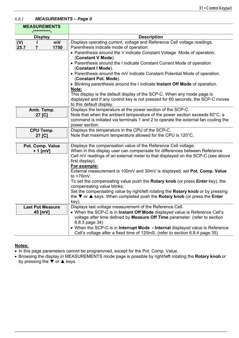
6.8.1 MEASUREMENTS – Page 0
MEASUREMENTS -**********-
Display Description (V) I mV 25.7 7 1750
Displays operating current, voltage and Reference Cell voltage readings. Parenthesis indicate mode of operation: • Parenthesis around the V indicate Constant Voltage Mode of operation.
(Constant V Mode). • Parenthesis around the I indicate Constant Current Mode of operation
(Constant I Mode). • Parenthesis around the mV indicate Constant Potential Mode of operation.
(Constant Pot. Mode). • Blinking parenthesis around the I indicate Instant Off Mode of operation. Note: This display is the default display of the SCP-C. When any mode page is displayed and if any control key is not pressed for 60 seconds, the SCP-C moves to this default display.
Amb. Temp. 27 [C]
Displays the temperature at the power section of the SCP-C. Note that when the ambient temperature of the power section exceeds 60°C, a command is initiated via terminals 1 and 2 to operate the external fan cooling the power section.
CPU Temp. 27 [C]
Displays the temperature in the CPU of the SCP-C. Note that maximum temperature allowed for the CPU is 120°C.
Pot. Comp. Value + 1 [mV]
Displays the compensation value of the Reference Cell voltage. When in this display user can compensate for differences between Reference Cell mV readings of an external meter to that displayed on the SCP-C (see above first display). For example: External measurement is 100mV and 30mV is displayed, set Pot. Comp. Value to +70mV. To set the compensating value push the Rotary knob (or press Enter key), the compensating value blinks. Set the compensating value by right/left rotating the Rotary knob or by pressing the or keys. When completed push the Rotary knob (or press the Enter key).
Last Pot Measure 45 [mV]
Displays last voltage measurement of the Reference Cell. • When the SCP-C is in Instant Off Mode displayed value is Reference Cell’s
voltage after time defined by Measure Off Time parameter. (refer to section 1 6.8.3 page 134)
• When the SCP-C is in Interrupt Mode - Internal displayed value is Reference Cell’s voltage after a fixed time of 120mS. (refer to section 1 6.8.4 page 135)
Notes: • In this page parameters cannot be programmed, except for the Pot. Comp. Value. • Browsing the display in MEASUREMENTS mode page is possible by right/left rotating the Rotary knob or
by pressing the or keys.
32 • Control Keypad
________________________________________________________________________________________________
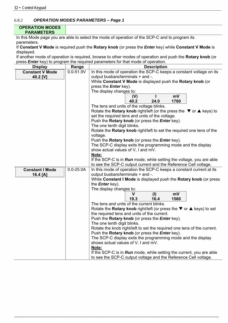
6.8.2 OPERATION MODES PARAMETERS – Page 1
OPERATION MODES PARAMETERS
In this Mode page you are able to select the mode of operation of the SCP-C and to program its parameters. If Constant V Mode is required push the Rotary knob (or press the Enter key) while Constant V Mode is displayed. If another mode of operation is required, browse to other modes of operation and push the Rotary knob (or press Enter key) to program the required parameters for that mode of operation.
Display Range Description Constant V Mode
40.2 [V] 0.0-51.9V In this mode of operation the SCP-C keeps a constant voltage on its
output busbars/terminals + and -. While Constant V Mode is displayed push the Rotary knob (or press the Enter key). The display changes to:
(V) I mV 40.2 24.0 1760
The tens and units of the voltage blinks. Rotate the Rotary knob right/left (or the press the or keys) to set the required tens and units of the voltage. Push the Rotary knob (or press the Enter key). The one tenth digit blinks. Rotate the Rotary knob right/left to set the required one tens of the voltage. Push the Rotary knob (or press the Enter key). The SCP-C display exits the programming mode and the display show actual values of V, I and mV. Note: If the SCP-C is in Run mode, while setting the voltage, you are able to see the SCP-C output current and the Reference Cell voltage.
Constant I Mode 16.4 [A]
0.0-25.0A In this mode of operation the SCP-C keeps a constant current at its output busbars/terminals + and -. While Constant I Mode is displayed push the Rotary knob (or press the Enter key). The display changes to:
V (I) mV 19.3 16.4 1560
The tens and units of the current blinks. Rotate the Rotary knob right/left (or press the or keys) to set the required tens and units of the current. Push the Rotary knob (or press the Enter key). The one tenth digit blinks. Rotate the knob right/left to set the required one tens of the current. Push the Rotary knob (or press the Enter key). The SCP-C display exits the programming mode and the display shows actual values of V, I and mV. Note: If the SCP-C is in Run mode, while setting the current, you are able to see the SCP-C output voltage and the Reference Cell voltage.
33 • Control Keypad
_______________________________________________________________________________________________
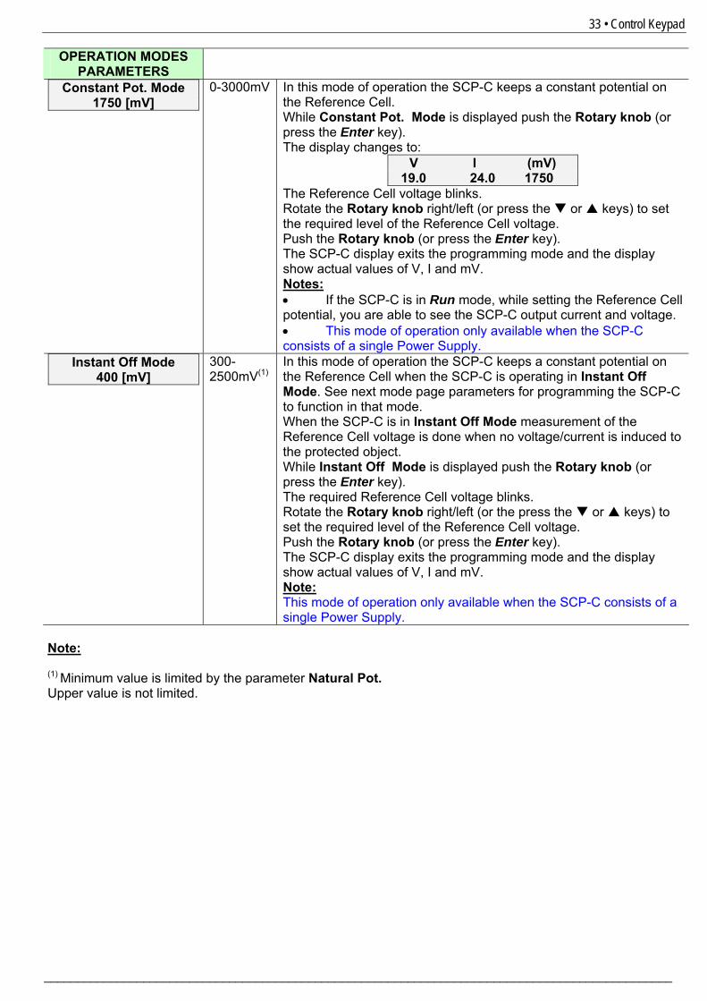
OPERATION MODES PARAMETERS
Constant Pot. Mode 1750 [mV]
0-3000mV In this mode of operation the SCP-C keeps a constant potential on the Reference Cell. While Constant Pot. Mode is displayed push the Rotary knob (or press the Enter key). The display changes to:
V I (mV) 19.0 24.0 1750
The Reference Cell voltage blinks. Rotate the Rotary knob right/left (or press the or keys) to set the required level of the Reference Cell voltage. Push the Rotary knob (or press the Enter key). The SCP-C display exits the programming mode and the display show actual values of V, I and mV. Notes: • If the SCP-C is in Run mode, while setting the Reference Cell potential, you are able to see the SCP-C output current and voltage. • This mode of operation only available when the SCP-C consists of a single Power Supply.
Instant Off Mode 400 [mV]
300-2500mV(1)
In this mode of operation the SCP-C keeps a constant potential on the Reference Cell when the SCP-C is operating in Instant Off Mode. See next mode page parameters for programming the SCP-C to function in that mode. When the SCP-C is in Instant Off Mode measurement of the Reference Cell voltage is done when no voltage/current is induced to the protected object. While Instant Off Mode is displayed push the Rotary knob (or press the Enter key). The required Reference Cell voltage blinks. Rotate the Rotary knob right/left (or the press the or keys) to set the required level of the Reference Cell voltage. Push the Rotary knob (or press the Enter key). The SCP-C display exits the programming mode and the display show actual values of V, I and mV. Note: This mode of operation only available when the SCP-C consists of a single Power Supply.
Note: (1) Minimum value is limited by the parameter Natural Pot. Upper value is not limited.
34 • Control Keypad
________________________________________________________________________________________________
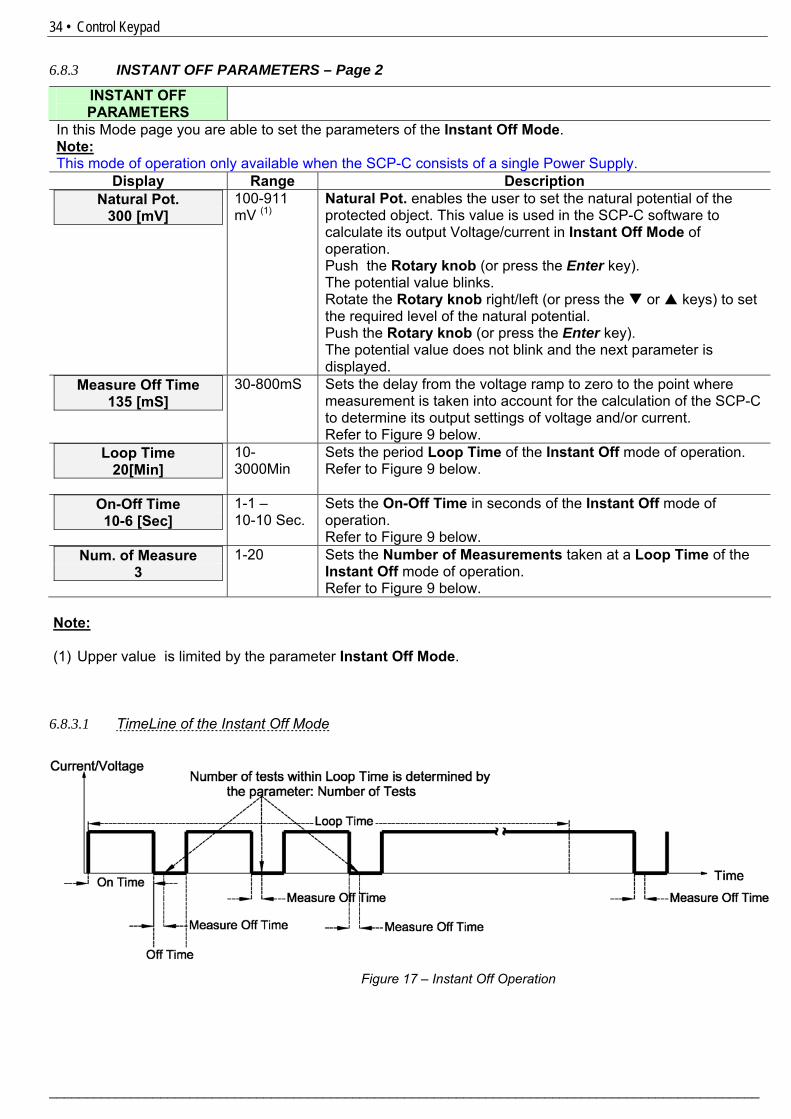
6.8.3 INSTANT OFF PARAMETERS – Page 2
INSTANT OFF PARAMETERS
In this Mode page you are able to set the parameters of the Instant Off Mode. Note: This mode of operation only available when the SCP-C consists of a single Power Supply.
Display Range Description Natural Pot.
300 [mV] 100-911 mV (1)
Natural Pot. enables the user to set the natural potential of the protected object. This value is used in the SCP-C software to calculate its output Voltage/current in Instant Off Mode of operation. Push the Rotary knob (or press the Enter key). The potential value blinks. Rotate the Rotary knob right/left (or press the or keys) to set the required level of the natural potential. Push the Rotary knob (or press the Enter key). The potential value does not blink and the next parameter is displayed.
Measure Off Time 135 [mS]
30-800mS Sets the delay from the voltage ramp to zero to the point where measurement is taken into account for the calculation of the SCP-C to determine its output settings of voltage and/or current. Refer to 1Figure 9 below.
Loop Time 20[Min]
10-3000Min
Sets the period Loop Time of the Instant Off mode of operation. Refer to 2Figure 9 below.
On-Off Time 10-6 [Sec]
1-1 – 10-10 Sec.
Sets the On-Off Time in seconds of the Instant Off mode of operation. Refer to 2Figure 9 below.
Num. of Measure 3
1-20 Sets the Number of Measurements taken at a Loop Time of the Instant Off mode of operation. Refer to 2Figure 9 below.
Note: (1) Upper value is limited by the parameter Instant Off Mode. 6.8.3.1 TimeLine of the Instant Off Mode
Figure 17 – Instant Off Operation
35 • Control Keypad
_______________________________________________________________________________________________
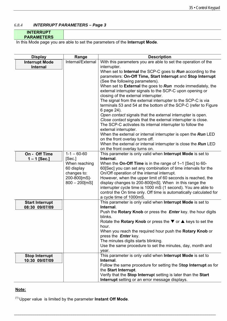
6.8.4 INTERRUPT PARAMETERS – Page 3
INTERRUPT PARAMETERS
In this Mode page you are able to set the parameters of the Interrupt Mode.
Display Range Description Interrupt Mode
Internal Internal/External With this parameters you are able to set the operation of the
interrupter. When set to Internal the SCP-C goes to Run according to the parameters: On-Off Time, Start Interrupt and Stop Interrupt (See the following parameters). When set to External the goes to Run mode immediately, the external interrupter signals to the SCP-C upon opening or closing of the external interrupter. The signal from the external interrupter to the SCP-C is via terminals 53 and 54 at the bottom of the SCP-C (refer to 2Figure 6 page 224). Open contact signals that the external interrupter is open. Close contact signals that the external interrupter is close. The SCP-C activates its internal interrupter to follow the external interrupter. When the external or internal interrupter is open the Run LED on the front overlay turns off. When the external or internal interrupter is close the Run LED on the front overlay turns on.
On - Off Time 1 – 1 [Sec.]
1-1 – 60-60 [Sec.] When reaching 60 display changes to: 200-800[mS]- 800 – 200[mS]
This parameter is only valid when Interrupt Mode is set to Internal. When the On-Off Time is in the range of 1–1 [Sec] to 60-60[Sec] you can set any combination of time intervals for the On/Off operation of the internal interrupt. However, when the upper limit of 60 seconds is reached, the display changes to 200-800[mS]. When in this range the interrupter cycle time is 1000 mS (1 second). You are able to control the On time only. Off time is automatically calculated for a cycle time of 1000mS.
Start Interrupt 08:30 09/07/09
This parameter is only valid when Interrupt Mode is set to Internal. Push the Rotary Knob or press the Enter key. the hour digits blinks. Rotate the Rotary Knob or press the or keys to set the hour. When you reach the required hour push the Rotary Knob or press the Enter key. The minutes digits starts blinking. Use the same procedure to set the minutes, day, month and year.
Stop Interrupt 10:30 09/07/09
This parameter is only valid when Interrupt Mode is set to Internal. Follow the same procedure for setting the Stop Interrupt as for the Start Interrupt. Verify that the Stop Interrupt setting is later than the Start Interrupt setting or an error message displays.
Note: (1) Upper value is limited by the parameter Instant Off Mode.
36 • Control Keypad
________________________________________________________________________________________________
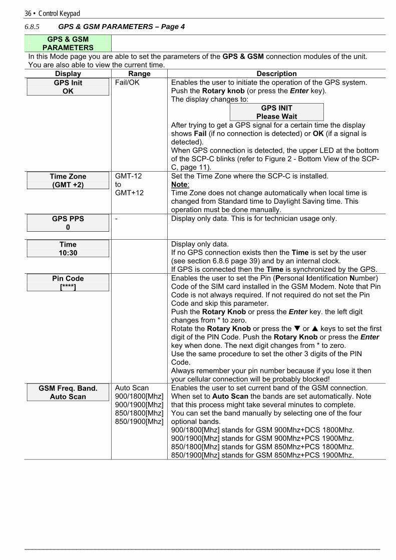
6.8.5 GPS & GSM PARAMETERS – Page 4
GPS & GSM PARAMETERS
In this Mode page you are able to set the parameters of the GPS & GSM connection modules of the unit. You are also able to view the current time.
Display Range Description GPS Init
OK Fail/OK Enables the user to initiate the operation of the GPS system.
Push the Rotary knob (or press the Enter key). The display changes to:
GPS INIT Please Wait
After trying to get a GPS signal for a certain time the display shows Fail (if no connection is detected) or OK (if a signal is detected). When GPS connection is detected, the upper LED at the bottom of the SCP-C blinks (refer to 2Figure 2 - Bottom View of the SCP-C, page 211).
Time Zone (GMT +2)
GMT-12 to GMT+12
Set the Time Zone where the SCP-C is installed. Note: Time Zone does not change automatically when local time is changed from Standard time to Daylight Saving time. This operation must be done manually.
GPS PPS 0
- Display only data. This is for technician usage only.
Time 10:30
Display only data. If no GPS connection exists then the Time is set by the user (see section 2 6.8.6 page 239) and by an internal clock. If GPS is connected then the Time is synchronized by the GPS.
Pin Code [****]
Enables the user to set the Pin (Personal Identification Number) Code of the SIM card installed in the GSM Modem. Note that Pin Code is not always required. If not required do not set the Pin Code and skip this parameter. Push the Rotary Knob or press the Enter key. the left digit changes from * to zero. Rotate the Rotary Knob or press the or keys to set the first digit of the PIN Code. Push the Rotary Knob or press the Enter key when done. The next digit changes from * to zero. Use the same procedure to set the other 3 digits of the PIN Code. Always remember your pin number because if you lose it then your cellular connection will be probably blocked!
GSM Freq. Band. Auto Scan
Auto Scan 900/1800[Mhz] 900/1900[Mhz] 850/1800[Mhz] 850/1900[Mhz]
Enables the user to set current band of the GSM connection. When set to Auto Scan the bands are set automatically. Note that this process might take several minutes to complete. You can set the band manually by selecting one of the four optional bands. 900/1800[Mhz] stands for GSM 900Mhz+DCS 1800Mhz. 900/1900[Mhz] stands for GSM 900Mhz+PCS 1900Mhz. 850/1800[Mhz] stands for GSM 850Mhz+PCS 1800Mhz. 850/1900[Mhz] stands for GSM 850Mhz+PCS 1900Mhz.
37 • Control Keypad
_______________________________________________________________________________________________
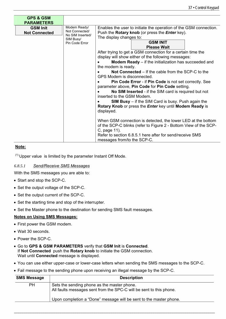
GPS & GSM PARAMETERS
GSM Init Not Connected
Modem Ready/ Not Connected/ No SIM Inserted/ SIM Busy/ Pin Code Error
Enables the user to initiate the operation of the GSM connection. Push the Rotary knob (or press the Enter key). The display changes to:
GSM INIT Please Wait
After trying to get a GSM connection for a certain time the display will show either of the following messages: • Modem Ready – if the initialization has succeeded and the modem is ready. • Not Connected – If the cable from the SCP-C to the GPS Modem is disconnected. • Pin Code Error - if Pin Code is not set correctly. See parameter above, Pin Code for Pin Code setting. • No SIM Inserted - if the SIM card is required but not inserted to the GSM Modem. • SIM Busy – if the SIM Card is busy. Push again the Rotary Knob or press the Enter key until Modem Ready is displayed. When GSM connection is detected, the lower LED at the bottom of the SCP-C blinks (refer to 2Figure 2 - Bottom View of the SCP-C, page 211). Refer to section 2 6.8.5.1 here after for send/receive SMS messages from/to the SCP-C.
Note: (1) Upper value is limited by the parameter Instant Off Mode. 6.8.5.1 Send/Receive SMS Messages
With the SMS messages you are able to:
• Start and stop the SCP-C.
• Set the output voltage of the SCP-C.
• Set the output current of the SCP-C.
• Set the starting time and stop of the interrupter.
• Set the Master phone to the destination for sending SMS fault messages.
Notes on Using SMS Messages:
• First power the GSM modem.
• Wait 30 seconds.
• Power the SCP-C.
• Go to GPS & GSM PARAMETERS verify that GSM Init is Connected. If Not Connected push the Rotary knob to initiate the GSM connection. Wait until Connected message is displayed.
• You can use either upper-case or lower-case letters when sending the SMS messages to the SCP-C.
• Fail message to the sending phone upon receiving an illegal message by the SCP-C.
SMS Message Description
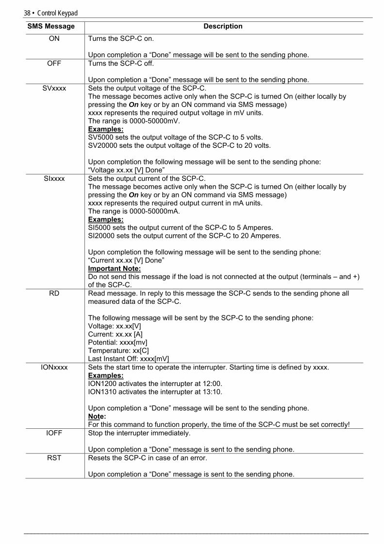
PH Sets the sending phone as the master phone. All faults messages sent from the SPC-C will be sent to this phone. Upon completion a “Done” message will be sent to the master phone.
38 • Control Keypad
________________________________________________________________________________________________
SMS Message Description
ON Turns the SCP-C on. Upon completion a “Done” message will be sent to the sending phone.
OFF Turns the SCP-C off. Upon completion a “Done” message will be sent to the sending phone.
SVxxxx Sets the output voltage of the SCP-C. The message becomes active only when the SCP-C is turned On (either locally by pressing the On key or by an ON command via SMS message) xxxx represents the required output voltage in mV units. The range is 0000-50000mV. Examples: SV5000 sets the output voltage of the SCP-C to 5 volts. SV20000 sets the output voltage of the SCP-C to 20 volts. Upon completion the following message will be sent to the sending phone: “Voltage xx.xx [V] Done”
SIxxxx Sets the output current of the SCP-C. The message becomes active only when the SCP-C is turned On (either locally by pressing the On key or by an ON command via SMS message) xxxx represents the required output current in mA units. The range is 0000-50000mA. Examples: SI5000 sets the output current of the SCP-C to 5 Amperes. SI20000 sets the output current of the SCP-C to 20 Amperes. Upon completion the following message will be sent to the sending phone: “Current xx.xx [V] Done” Important Note: Do not send this message if the load is not connected at the output (terminals – and +) of the SCP-C.
RD Read message. In reply to this message the SCP-C sends to the sending phone all measured data of the SCP-C. The following message will be sent by the SCP-C to the sending phone: Voltage: xx.xx[V] Current: xx.xx [A] Potential: xxxx[mv] Temperature: xx[C] Last Instant Off: xxxx[mV]
IONxxxx Sets the start time to operate the interrupter. Starting time is defined by xxxx. Examples: ION1200 activates the interrupter at 12:00. ION1310 activates the interrupter at 13:10. Upon completion a “Done” message will be sent to the sending phone. Note: For this command to function properly, the time of the SCP-C must be set correctly!
IOFF Stop the interrupter immediately. Upon completion a “Done” message is sent to the sending phone.
RST Resets the SCP-C in case of an error. Upon completion a “Done” message is sent to the sending phone.
39 • Control Keypad
_______________________________________________________________________________________________
6.8.6 GLOBAL PARAMETERS – Page 5
GLOBAL PARAMETERS
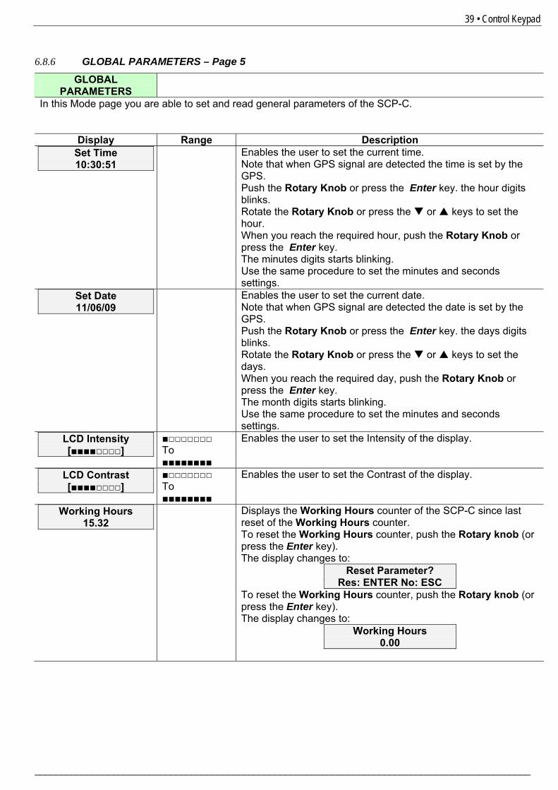
In this Mode page you are able to set and read general parameters of the SCP-C.
Display Range Description Set Time 10:30:51
Enables the user to set the current time. Note that when GPS signal are detected the time is set by the GPS. Push the Rotary Knob or press the Enter key. the hour digits blinks. Rotate the Rotary Knob or press the or keys to set the hour. When you reach the required hour, push the Rotary Knob or press the Enter key. The minutes digits starts blinking. Use the same procedure to set the minutes and seconds settings.
Set Date 11/06/09
Enables the user to set the current date. Note that when GPS signal are detected the date is set by the GPS. Push the Rotary Knob or press the Enter key. the days digits blinks. Rotate the Rotary Knob or press the or keys to set the days. When you reach the required day, push the Rotary Knob or press the Enter key. The month digits starts blinking. Use the same procedure to set the minutes and seconds settings.
LCD Intensity [■■■■□□□□]
■□□□□□□□ To ■■■■■■■■
Enables the user to set the Intensity of the display.
LCD Contrast [■■■■□□□□]
■□□□□□□□ To ■■■■■■■■
Enables the user to set the Contrast of the display.
Working Hours 15.32
Displays the Working Hours counter of the SCP-C since last reset of the Working Hours counter. To reset the Working Hours counter, push the Rotary knob (or press the Enter key). The display changes to:
Reset Parameter? Res: ENTER No: ESC
To reset the Working Hours counter, push the Rotary knob (or press the Enter key). The display changes to:
Working Hours 0.00
40 • Control Keypad
________________________________________________________________________________________________
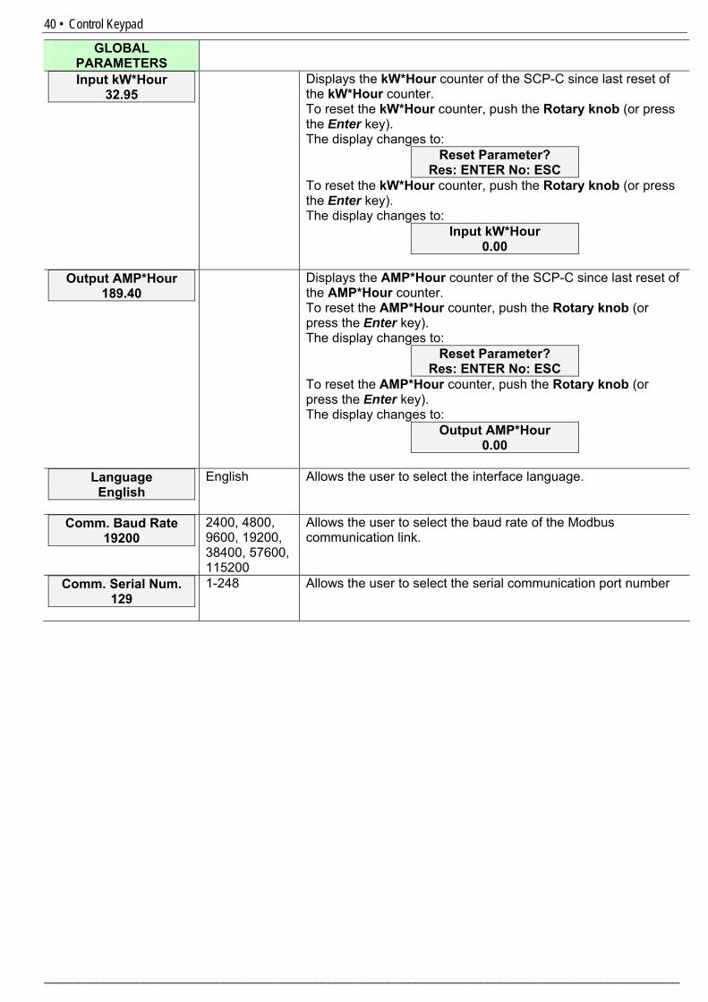
GLOBAL PARAMETERS
Input kW*Hour 32.95
Displays the kW*Hour counter of the SCP-C since last reset of the kW*Hour counter. To reset the kW*Hour counter, push the Rotary knob (or press the Enter key). The display changes to:
Reset Parameter? Res: ENTER No: ESC
To reset the kW*Hour counter, push the Rotary knob (or press the Enter key). The display changes to:
Input kW*Hour 0.00
Output AMP*Hour
189.40 Displays the AMP*Hour counter of the SCP-C since last reset of
the AMP*Hour counter. To reset the AMP*Hour counter, push the Rotary knob (or press the Enter key). The display changes to:
Reset Parameter? Res: ENTER No: ESC
To reset the AMP*Hour counter, push the Rotary knob (or press the Enter key). The display changes to:
Output AMP*Hour 0.00
Language
English English Allows the user to select the interface language.
Comm. Baud Rate 19200
2400, 4800, 9600, 19200, 38400, 57600, 115200
Allows the user to select the baud rate of the Modbus communication link.
Comm. Serial Num. 129
1-248 Allows the user to select the serial communication port number
41 • Control Keypad
_______________________________________________________________________________________________
6.8.7 IRRIGATION CTRL PARAMETERS – Page 6
IRRIGATION CTRL PARAMETERS
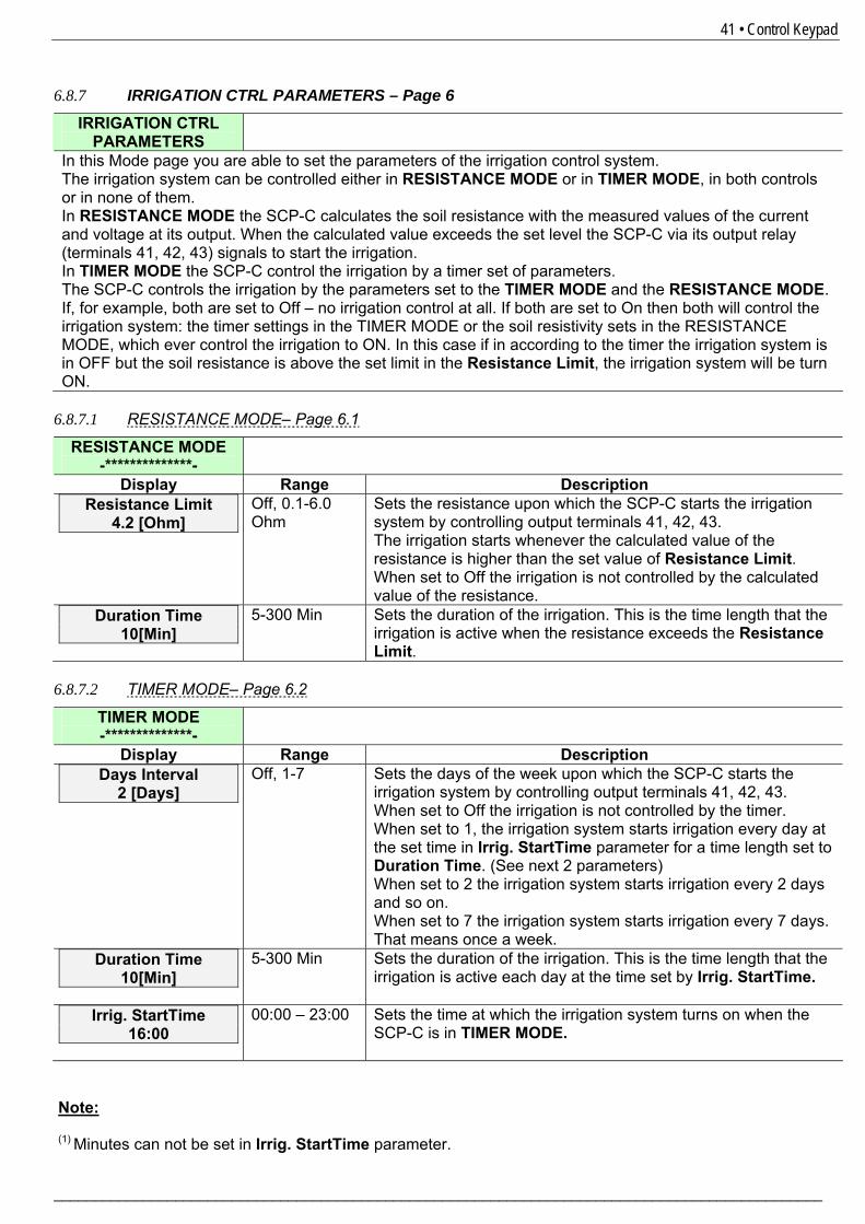
In this Mode page you are able to set the parameters of the irrigation control system. The irrigation system can be controlled either in RESISTANCE MODE or in TIMER MODE, in both controls or in none of them. In RESISTANCE MODE the SCP-C calculates the soil resistance with the measured values of the current and voltage at its output. When the calculated value exceeds the set level the SCP-C via its output relay (terminals 41, 42, 43) signals to start the irrigation. In TIMER MODE the SCP-C control the irrigation by a timer set of parameters. The SCP-C controls the irrigation by the parameters set to the TIMER MODE and the RESISTANCE MODE. If, for example, both are set to Off – no irrigation control at all. If both are set to On then both will control the irrigation system: the timer settings in the TIMER MODE or the soil resistivity sets in the RESISTANCE MODE, which ever control the irrigation to ON. In this case if in according to the timer the irrigation system is in OFF but the soil resistance is above the set limit in the Resistance Limit, the irrigation system will be turn ON. 6.8.7.1 RESISTANCE MODE– Page 6.1
RESISTANCE MODE -**************-
Display Range Description Resistance Limit
4.2 [Ohm] Off, 0.1-6.0 Ohm
Sets the resistance upon which the SCP-C starts the irrigation system by controlling output terminals 41, 42, 43. The irrigation starts whenever the calculated value of the resistance is higher than the set value of Resistance Limit. When set to Off the irrigation is not controlled by the calculated value of the resistance.
Duration Time 10[Min]
5-300 Min Sets the duration of the irrigation. This is the time length that the irrigation is active when the resistance exceeds the Resistance Limit.
6.8.7.2 TIMER MODE– Page 6.2
TIMER MODE -**************-
Display Range Description Days Interval
2 [Days] Off, 1-7 Sets the days of the week upon which the SCP-C starts the
irrigation system by controlling output terminals 41, 42, 43. When set to Off the irrigation is not controlled by the timer. When set to 1, the irrigation system starts irrigation every day at the set time in Irrig. StartTime parameter for a time length set to Duration Time. (See next 2 parameters) When set to 2 the irrigation system starts irrigation every 2 days and so on. When set to 7 the irrigation system starts irrigation every 7 days. That means once a week.
Duration Time 10[Min]
5-300 Min Sets the duration of the irrigation. This is the time length that the irrigation is active each day at the time set by Irrig. StartTime.
Irrig. StartTime 16:00
00:00 – 23:00
Sets the time at which the irrigation system turns on when the SCP-C is in TIMER MODE.
Note: (1) Minutes can not be set in Irrig. StartTime parameter.
42 • Control Keypad
________________________________________________________________________________________________
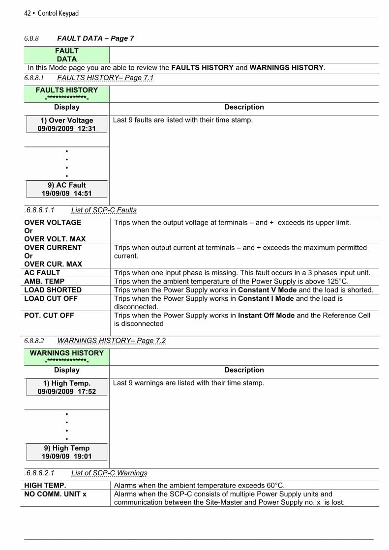
6.8.8 FAULT DATA – Page 7
FAULT DATA
In this Mode page you are able to review the FAULTS HISTORY and WARNINGS HISTORY. 6.8.8.1 FAULTS HISTORY– Page 7.1
FAULTS HISTORY -**************-
Display Description
1) Over Voltage 09/09/2009 12:31
• • • •
9) AC Fault 19/09/09 14:51
Last 9 faults are listed with their time stamp.
.6.8.8.1.1 List of SCP-C Faults
OVER VOLTAGE Or OVER VOLT. MAX
Trips when the output voltage at terminals – and + exceeds its upper limit.
OVER CURRENT Or OVER CUR. MAX
Trips when output current at terminals – and + exceeds the maximum permitted current.
AC FAULT Trips when one input phase is missing. This fault occurs in a 3 phases input unit. AMB. TEMP Trips when the ambient temperature of the Power Supply is above 125°C. LOAD SHORTED Trips when the Power Supply works in Constant V Mode and the load is shorted. LOAD CUT OFF Trips when the Power Supply works in Constant I Mode and the load is
disconnected. POT. CUT OFF Trips when the Power Supply works in Instant Off Mode and the Reference Cell
is disconnected
6.8.8.2 WARNINGS HISTORY– Page 7.2
WARNINGS HISTORY -**************-
Display Description
1) High Temp. 09/09/2009 17:52
• • • •
9) High Temp 19/09/09 19:01
Last 9 warnings are listed with their time stamp.
.6.8.8.2.1 List of SCP-C Warnings
HIGH TEMP. Alarms when the ambient temperature exceeds 60°C. NO COMM. UNIT x Alarms when the SCP-C consists of multiple Power Supply units and
communication between the Site-Master and Power Supply no. x is lost.
43 • Control Keypad
_______________________________________________________________________________________________
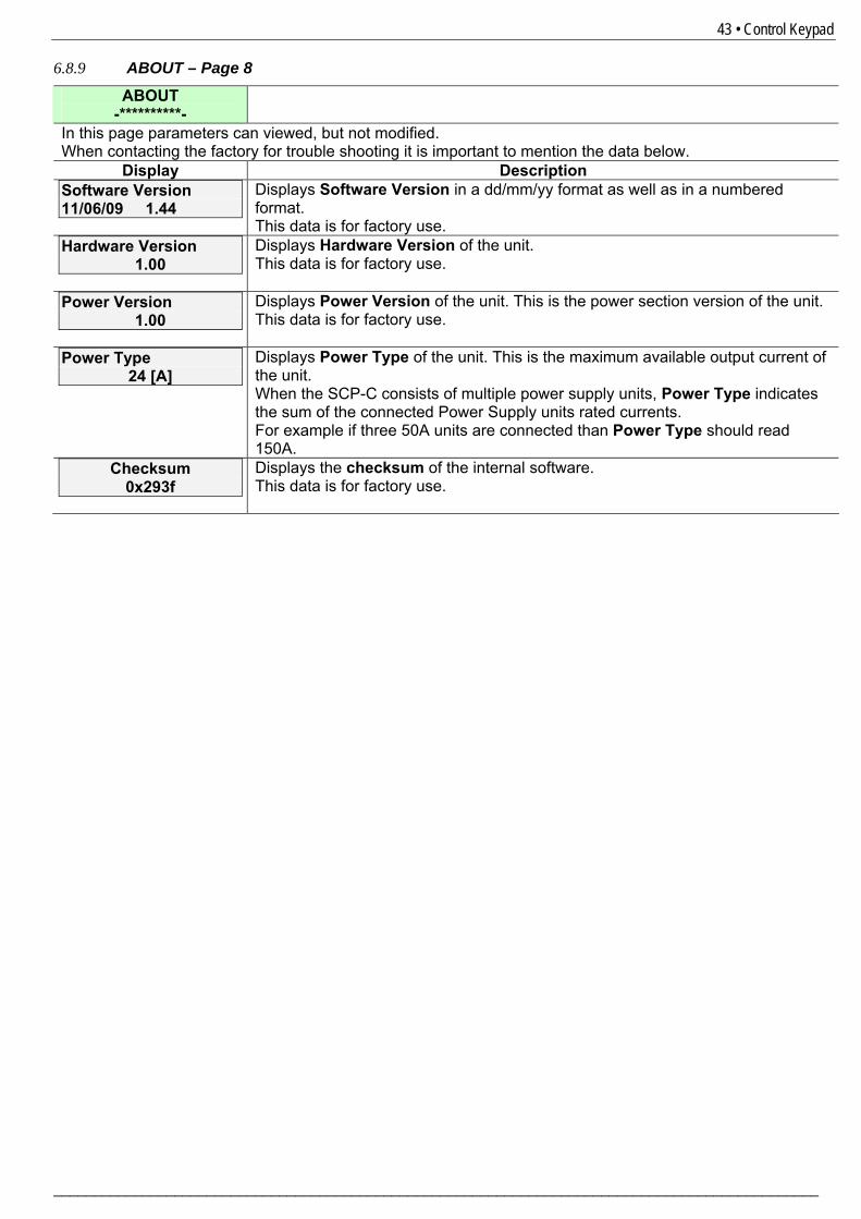
6.8.9 ABOUT – Page 8
ABOUT -**********-
In this page parameters can viewed, but not modified. When contacting the factory for trouble shooting it is important to mention the data below.
Display Description Software Version 11/06/09 1.44
Displays Software Version in a dd/mm/yy format as well as in a numbered format. This data is for factory use.
Hardware Version 1.00
Displays Hardware Version of the unit. This data is for factory use.
Power Version 1.00
Displays Power Version of the unit. This is the power section version of the unit. This data is for factory use.
Power Type 24 [A]
Displays Power Type of the unit. This is the maximum available output current of the unit. When the SCP-C consists of multiple power supply units, Power Type indicates the sum of the connected Power Supply units rated currents. For example if three 50A units are connected than Power Type should read 150A.
Checksum 0x293f
Displays the checksum of the internal software. This data is for factory use.
44 • Cabinet Installation
________________________________________________________________________________________________
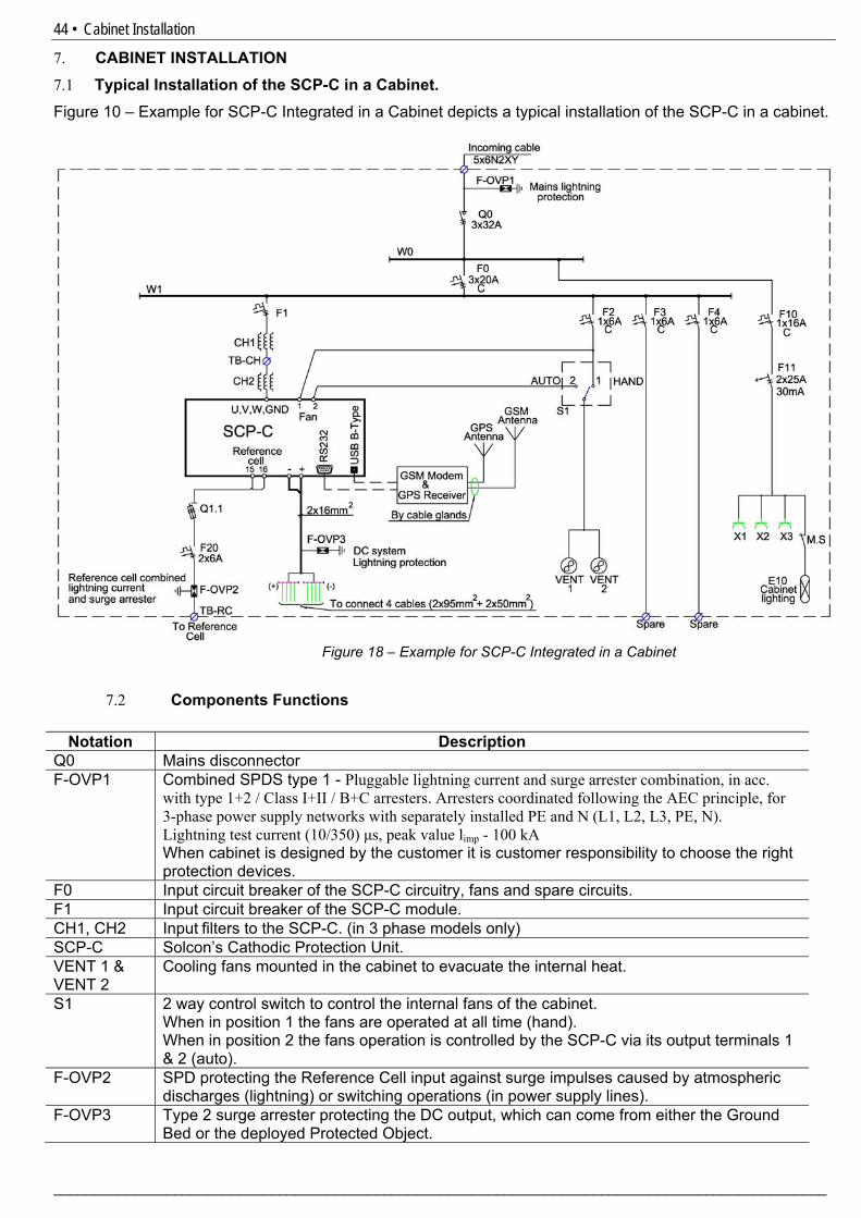
7. CABINET INSTALLATION 7.1 Typical Installation of the SCP-C in a Cabinet. 2Figure 10 – Example for SCP-C Integrated in a Cabinet depicts a typical installation of the SCP-C in a cabinet.
Figure 18 – Example for SCP-C Integrated in a Cabinet
7.2 Components Functions
Notation Description Q0 Mains disconnector F-OVP1 Combined SPDS type 1 - Pluggable lightning current and surge arrester combination, in acc.
with type 1+2 / Class I+II / B+C arresters. Arresters coordinated following the AEC principle, for 3-phase power supply networks with separately installed PE and N (L1, L2, L3, PE, N). Lightning test current (10/350) μs, peak value limp - 100 kA When cabinet is designed by the customer it is customer responsibility to choose the right protection devices.
F0 Input circuit breaker of the SCP-C circuitry, fans and spare circuits. F1 Input circuit breaker of the SCP-C module. CH1, CH2 Input filters to the SCP-C. (in 3 phase models only) SCP-C Solcon’s Cathodic Protection Unit. VENT 1 & VENT 2
Cooling fans mounted in the cabinet to evacuate the internal heat.
S1 2 way control switch to control the internal fans of the cabinet. When in position 1 the fans are operated at all time (hand). When in position 2 the fans operation is controlled by the SCP-C via its output terminals 1 & 2 (auto).
F-OVP2 SPD protecting the Reference Cell input against surge impulses caused by atmospheric discharges (lightning) or switching operations (in power supply lines).
F-OVP3 Type 2 surge arrester protecting the DC output, which can come from either the Ground Bed or the deployed Protected Object.
45 • Cabinet Installation
_______________________________________________________________________________________________
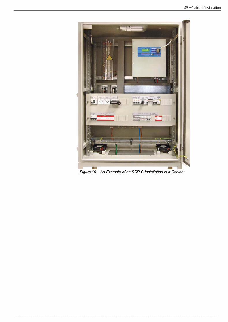
Figure 19 – An Example of an SCP-C Installation in a Cabinet
46 • Starting Procedure
________________________________________________________________________________________________
8. STARTING PROCEDURE 8.1 Starting Procedure for SCP-C Consisting of a Single Power Supply
Unpack the unit and visually inspect the unit. Verify that the unit was not damaged during transportation and/or installation.
Make all mechanical and electrical connections. Remember to short the Reference Cell input (terminals 15 & 16) if the Reference Cell is not connected.
Power the Hardware interface unit (if installed).
Wait 30 seconds.
Power the SCP-C unit.
Verify that the SCP-C is in the Off mode (On LED=On, Run LED=Off, Fault LED=Off). If the Run LED=On press the Stop key to stop the unit.
Go to GLOBAL PARAMETERS (refer to section 2 6.8.6 page 239) and do the following: □ Set Set Time and Set Date properly.
□ Reset Working Hours, Input kW*Hour and Output Amp*Hour. □ Set Modbus parameters: Comm. Baud Rate and Comm. Serial Num (If a Modbus connection exists)
Go to GPS & GSM PARAMETERS (refer to section 2 6.8.5 page 236) □ Verify that GPS INIT=OK (If a GPS receiver is installed). If not connected Initiate this connection.
□ Set Time Zone as required. (Note that the Time Zone does not change automatically from/to Standard and Daylight Saving Time! This modification must be done manually) □ Set Pin Code if required.
□ Set GSM Freq. Band as required. If not known leave this parameter in Auto Scan. Note that, when in Auto Scan, identifying the frequency band might take several minutes to complete. □ Verify that GSM Init=Connected (If a GSM receiver is installed). If not connected Initiate this connections.
Go to OPERATION MODES PARAMETERS (refer to section 2 6.8.2 page 232) □ Set the required mode of operation: Constant V Mode or Constant I Mode or Constant Pot. Mode or Instant Off Mode (If Instant Off Mode is selected set the required potential in the Instant Off Mode parameter). □ If either Constant V Mode or Constant I Mode or Constant Pot. Mode were selected go to MEASUREMENTS mode page and verify correct voltage, current or potential are measured. □ If Instant Off Mode is selected go to INSTANT OFF PARAMETERS (refer to section 2 6.8.3 page 234) and set all parameters in this mode page.
8.2 Starting Procedure for SCP-C Consisting of Multiple Power Supply Units
Unpack the Site-Master, CDU and the Power Supply units and visually inspect the units. Verify that the unit was not damaged during transportation and/or installation.
Make all mechanical and electrical connections. Remember to short the Reference Cell input (terminals 15 & 16 in the Site-Master) if the Reference Cell is not connected.
Power the Hardware interface unit (if installed).
47 • Starting Procedure
_______________________________________________________________________________________________
Power the Power Supply units. Verify that all Power Supply units are identical!
Wait 30 seconds.
Power the Site-Master. Verify that the Site-Master is in Off mode (On LED=On, Run LED=Off, Fault LED=Off).
If the Run LED=On press the Stop key to stop the unit.
Go to GLOBAL PARAMETERS (refer to section 2 6.8.6 page 239) and do the following: □ Set Set Time and Set Date properly.
□ Reset Working Hours, Input kW*Hour and Output Amp*Hour. □ Set Modbus parameters: Comm. Baud Rate and Comm. Serial Num (If a Modbus connection exists)
Go to GPS & GSM PARAMETERS (refer to section 2 6.8.5 page 236) □ Verify that GPS INIT=OK (If a GPS receiver is installed). If not connected Initiate this connection.
□ Set Time Zone as required. (Note that the Time Zone does not change automatically from/to Standard and Daylight Saving Time! This modification must be done manually) □ Set Pin Code if required.
□ Set GSM Freq. Band as required. If not known leave this parameter in Auto Scan. Note that, when in Auto Scan, identifying the frequency band might take several minutes to complete. □ Verify that GSM Init=Connected (If a GSM receiver is installed). If not connected Initiate this connections.
o Go to OPERATION MODES PARAMETERS (refer to section 2 6.8.2 page 232) □ Set the required mode of operation: Constant V Mode or Constant I Mode. Note that Constant Pot. Mode and Instant Off Mode are not available when the SCP-C consists of multiple power supply units. □ If either Constant V Mode or Constant I Mode were selected go to MEASUREMENTS mode page and verify that correct voltage or current are measured.
Upon powering the Site-Master system configuration is examined: o If communication link from the Site-Master to the CDU via 15 pin D-type connector is not
detected the following message will display: COMM. DISCONNECT FAIL
o If communication link from the CDU via 15 pin D-type connector to Power Supply No. 1 is not detected the following message will display: POWER UNIT 1 NO COMMUNICATION
o If communication link from the CDU via 15 pin D-type connector to Power Supply No. 2 is not detected the following message will display: POWER UNIT 2 NO COMMUNICATION Note that if Power Supply No. 3 is disconnected a fault message will not be initiated as only 2 Power Supply units are obligatory when operating with the Site-Master.
o If the Power Supply units are not identical the following message will display: NOT IDENTICAL POWER UNITS
o In order to reset the system from any of the above faults, the Power Supply units and the Site-Master power must be cycled.
Go to ABOUT (refer to section 6.8.9 page 2443) verify that Power Type indicates the sum of the connected Power Supply units’ rated currents. For example if three 50A units are connected than Power Type should read 150A. A communication failure between the Site-Master and any of the Power Supply units will result in a blinking Fault LED at the Site-Master and the following message to display in the WARNUNGS HISTORY: NO COMM. UNIT 1
48 • SCP-C Communication (Modbus Protocol)
________________________________________________________________________________________________
9. SCP-C COMMUNICATION (MODBUS PROTOCOL) 9.1 Introduction The SCP-C unit has one serial link for Modbus or other protocols. The Serial Link is RS485 type and the connector in D-type 15 pins. Features: * RS485 Hardware for serial link. * Asynchronous serial link. * Half duplex. * Format: - Modbus RTU Mode (Remote Terminal Unit Mode).
- Binary, - Each character includes 11 bits: - 1 Start bit - 8 Data bits, least significant bit sent first. - None Parity bit. - 1 Stop bit. - Cyclical Redundancy Check (CRC), 16 bits.
* Baud Rates: Modbus serial link (programmed): 2400, 4800, 9600, 19200, 38400, 57600, 115200 bits per second. * Response time of the Power Supply:
- Normally, Response Time ≤20mS. * After storing setting parameters, it is forbidden to retransmit to the same SCP-C unit in less than 1 Sec. * Broadcast commands: not supported. 9.2 Basic Structure of The Serial Link Frame Modbus RTU frame has the same principal structure for both the "Query" transmission from the Master to the SCP-C, and the Response transmission from the SCP-C to the Master: "Sync": Silent time of at least 3.5 character (3.5 * 11 bit times). Byte 1: Serial Link No. (= Slave Address) (1..247) Byte 2: Function (3,4,6,16 are supported) Byte 3: Data Bytes ($XX) . . ($XX) . . ($XX) Byte n-1:CRC_Low ($XX) Byte n : CRC_High ($XX) "Sync": Silent time of at least 3.5 character (3.5 * 11 bit times). 9.2.1 Sync (Silent Interval) In RTU mode, messages "synchronize" by a "Silent Interval" of more than 3.5 character times. This Silent Interval separates between transmission frames. The entire frame must be transmitted as a continuous stream. A silent time of more than 3.5 character times during frame transmission causes the receiving device to ignore the incomplete frame. Next byte is assumed to be the Serial Link No. of the next frame. The same result, of ignoring the frame, can occur if a second message is transmitted before 3.5 character times from the end of the previous one. This causes the receiving device to consider it as a continuation of the first frame, resulting in a CRC error. 9.2.2 Serial Link No. (Slave Address) Contains Power Supply Slave Number (1..247) on the serial link. The Power Supply default value is 248, which is the communication OFF condition. Serial Link No. is used as the first byte in both the "Query" transmission from Master to Slave and in Response transmission from Slave to Master.
49 • SCP-C Communication (Modbus Protocol)
_______________________________________________________________________________________________
9.2.3 Function The Function code informs the SCP-C of the requested action to take. In normal cases, Function is used as the second byte in both the "Query" transmission from Master to Slave and in Response transmission from Slave to Master. LIST OF FUNCTIONS SUPPORTED BY THE SCP-C Function Modbus Name Use in SCP-C 03 Read Holding Registers. Read Setting Parameters.
Read Actual Data (for Modbus Plus users) 04 Read Input Registers. Read Actual Data. 06 Preset Single Register. Write One Setting Parameter. 16 Force Multiple Registers Write Setting Parameters Control Commands 9.2.4 Data Data field includes information transferred to and from the Power Supply. The specific data format is changed with Function. While Word data parameters are transmitted, High Byte is transmitted first, followed by the Low Byte. 9.2.5 CRC The CRC (Cyclic Redundancy Check) two bytes (16 bit) are used to check the entire frame bytes. It is generated in the master device and transmitted as the last two bytes of the frame (Low byte is appended first, followed by the High byte). The slave device generates the CRC bytes again and compares it to the received CRC bytes. If the CRC bytes are not identical, the frame is flushed and no response is transmitted to the master. SCP-C MEMORY ORGANIZATION The SCP-C memory is organized according to the common Modbus addresses as follows: SCP-C Use Memory Type ` Max Query/Response Parameters Actual Data 3X References 256 Registers, # 1..256, addressed 0..255. 4X References 256 Registers, # 257..512, addressed 256..511 Setting Parameters 4X References 256 Registers, # 1..256, addressed 0..255
Notes:
• Actual Data parameters can be read both at 3X references starting at parameter #1, or (same parameters) at 4X references starting at parameter #257 (100 hex higher). The additional mapping in 4X references is designed for the convenience of Modbus Plus users.
• Cathode protection Power Supply can be controlled by writing to setting parameter #1 with function 6 or 16.
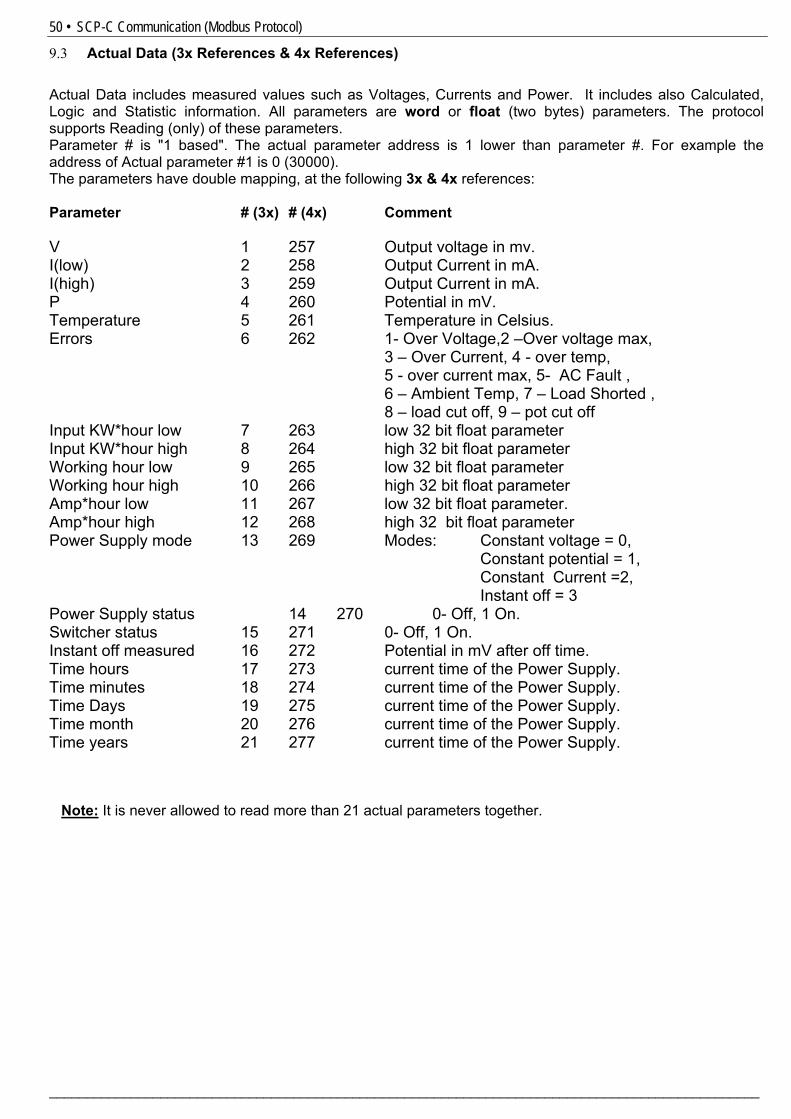
50 • SCP-C Communication (Modbus Protocol)
________________________________________________________________________________________________
9.3 Actual Data (3x References & 4x References) Actual Data includes measured values such as Voltages, Currents and Power. It includes also Calculated, Logic and Statistic information. All parameters are word or float (two bytes) parameters. The protocol supports Reading (only) of these parameters. Parameter # is "1 based". The actual parameter address is 1 lower than parameter #. For example the address of Actual parameter #1 is 0 (30000). The parameters have double mapping, at the following 3x & 4x references: Parameter # (3x) # (4x) Comment V 1 257 Output voltage in mv. I(low) 2 258 Output Current in mA. I(high) 3 259 Output Current in mA. P 4 260 Potential in mV. Temperature 5 261 Temperature in Celsius. Errors 6 262 1- Over Voltage,2 –Over voltage max, 3 – Over Current, 4 - over temp, 5 - over current max, 5- AC Fault , 6 – Ambient Temp, 7 – Load Shorted , 8 – load cut off, 9 – pot cut off Input KW*hour low 7 263 low 32 bit float parameter Input KW*hour high 8 264 high 32 bit float parameter Working hour low 9 265 low 32 bit float parameter Working hour high 10 266 high 32 bit float parameter Amp*hour low 11 267 low 32 bit float parameter. Amp*hour high 12 268 high 32 bit float parameter Power Supply mode 13 269 Modes: Constant voltage = 0, Constant potential = 1, Constant Current =2, Instant off = 3 Power Supply status 14 270 0- Off, 1 On. Switcher status 15 271 0- Off, 1 On. Instant off measured 16 272 Potential in mV after off time. Time hours 17 273 current time of the Power Supply. Time minutes 18 274 current time of the Power Supply. Time Days 19 275 current time of the Power Supply. Time month 20 276 current time of the Power Supply. Time years 21 277 current time of the Power Supply. Note: It is never allowed to read more than 21 actual parameters together.
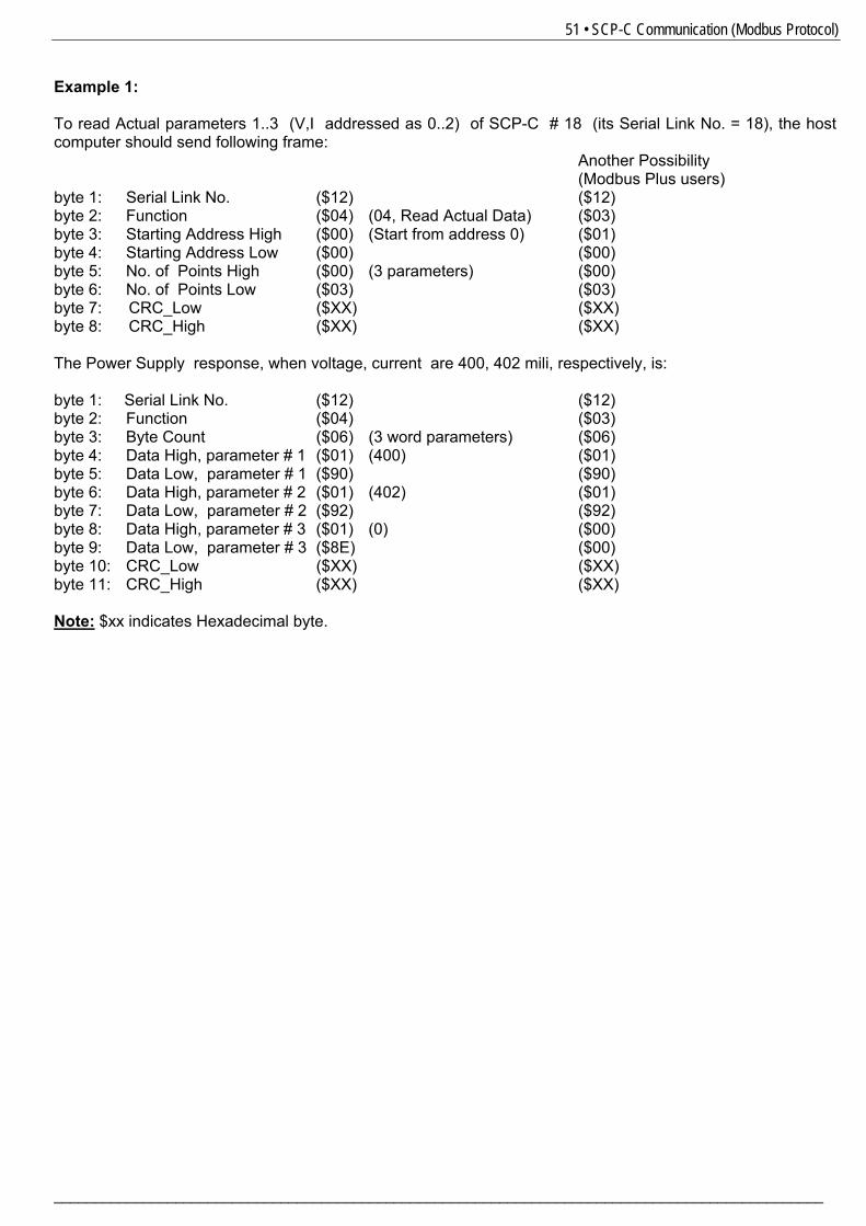
51 • SCP-C Communication (Modbus Protocol)
_______________________________________________________________________________________________
Example 1: To read Actual parameters 1..3 (V,I addressed as 0..2) of SCP-C # 18 (its Serial Link No. = 18), the host computer should send following frame:
Another Possibility (Modbus Plus users)
byte 1: Serial Link No. ($12) ($12) byte 2: Function ($04) (04, Read Actual Data) ($03) byte 3: Starting Address High ($00) (Start from address 0) ($01) byte 4: Starting Address Low ($00) ($00) byte 5: No. of Points High ($00) (3 parameters) ($00) byte 6: No. of Points Low ($03) ($03) byte 7: CRC_Low ($XX) ($XX) byte 8: CRC_High ($XX) ($XX) The Power Supply response, when voltage, current are 400, 402 mili, respectively, is: byte 1: Serial Link No. ($12) ($12) byte 2: Function ($04) ($03) byte 3: Byte Count ($06) (3 word parameters) ($06) byte 4: Data High, parameter # 1 ($01) (400) ($01) byte 5: Data Low, parameter # 1 ($90) ($90) byte 6: Data High, parameter # 2 ($01) (402) ($01) byte 7: Data Low, parameter # 2 ($92) ($92) byte 8: Data High, parameter # 3 ($01) (0) ($00) byte 9: Data Low, parameter # 3 ($8E) ($00) byte 10: CRC_Low ($XX) ($XX) byte 11: CRC_High ($XX) ($XX) Note: $xx indicates Hexadecimal byte.
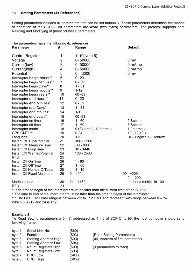
52 • SCP-C Communication (Modbus Protocol)
______________________________________________________________________________________
9.4 Setting Parameters (4x References) Setting parameters includes all parameters that can be set manually. These parameters determine the modes of operation of the SCP-C. All parameters are word (two bytes) parameters. The protocol supports both Reading and Modifying of (most of) these parameters. The parameters have the following 4x references: Parameter # Range Default Control Register 1 1- 10(Note 6) Voltage 2 0- 50000 0 mv Current(low) 3 0- 50000 0 mAmp Current(high) 4 0- 50000 0 mAmp Potential 5 0 – 3000 0 mv Interrupter begin hours** 6 0- 23 Interrupter begin Minutes** 7 0 - 59 Interrupter begin Days** 8 1 - 31 Interrupter begin mouths** 9 1-12 Interrupter begin years** 10 00 -63 Interrupter end hours* 11 0- 23 Interrupter end Minutes* 12 0 - 59 Interrupter end Days* 13 1 - 31 Interrupter end mouths* 14 1-12 Interrupter end years* 15 00 -63 Interrupter on time 16 1 - 60 2 Second Interrupter off time 17 1 - 60 8 Second Interrupter mode 18 0 (External), 1(Internal) 1 (Internal) GPS GMT*** 19 0-24 12 ( 12 =0 ) Language 20 0 -1 0 – English,1 - Hebrew InstantOff. PipePotenial 21 100 - 2500 InstantOff MeasureTime 22 30 - 800 InstantOff LoopTime 23 10 - 1440 InstantOff WantedPotenial 24 100 - 2500 RFU 25 InstantOff OnTime 26 1 - 60 InstantOff OffTime 27 1 - 60 InstantOff NumberOfTests 28 1 - 10 InstantOff Fixed Measure 29 0 – 400 400 - +200 0 - - 200 Modbus baud 30 24 – 1152 the baud multipli in 100 RFU 31 ** The time to begin of the interrupter must be later than the current time of the SCP-C, * The time to end of the interrupter must be later than the time to begin of the interrupter *** The GPS GMT time range is between -12 to +12 GMT and represent with range between 0 – 24 Which 0 is -12 and 24 is +12. Example 2: To Read Setting parameters # 5 - 7, addressed as 4 - 6 of SCP-C # 96, the host computer should send following frame: byte 1: Serial Link No. ($60) byte 2: Function ($03) (Read Setting Parameters) byte 3: Starting Address High ($00) (04, Address of first parameter) byte 4: Starting Address Low ($04) byte 5: No. of Registers High ($00) (3 parameters to read) byte 6: No. of Registers Low ($03) byte 7: CRC_Low ($XX) byte 8: CRC_High ($XX)
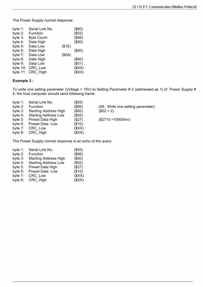
53 • SCP-C Communication (Modbus Protocol)
_______________________________________________________________________________________________
The Power Supply normal response: byte 1: Serial Link No. ($60) byte 2: Function ($03) byte 3: Byte Count ($06) byte 4: Data High ($00) byte 5: Data Low ($1E) byte 6: Data High ($00) byte 7: Data Low ($0A) byte 8: Data High ($00) byte 9: Data Low ($01) byte 10: CRC_Low ($XX) byte 11: CRC_High ($XX) Example 3 : To write one setting parameter (Voltage = 10V) to Setting Parameter # 2 (addressed as 1) of Power Supply # 5, the host computer should send following frame: byte 1: Serial Link No. ($05) byte 2: Function ($06) (06, Write one setting parameter) byte 3: Starting Address High ($00) ($02 = 2) byte 4: Starting Address Low ($02) byte 5: Preset Data High ($27) ($2710 =10000mv) byte 6: Preset Data Low ($10) byte 7: CRC_Low ($XX) byte 8: CRC_High ($XX) The Power Supply normal response is an echo of the query: byte 1: Serial Link No. ($05) byte 2: Function ($06) byte 3: Starting Address High ($00) byte 4: Starting Address Low ($02) byte 5: Preset Data High ($27) byte 6: Preset Data Low ($10) byte 7: CRC_Low ($XX) byte 8: CRC_High ($XX)
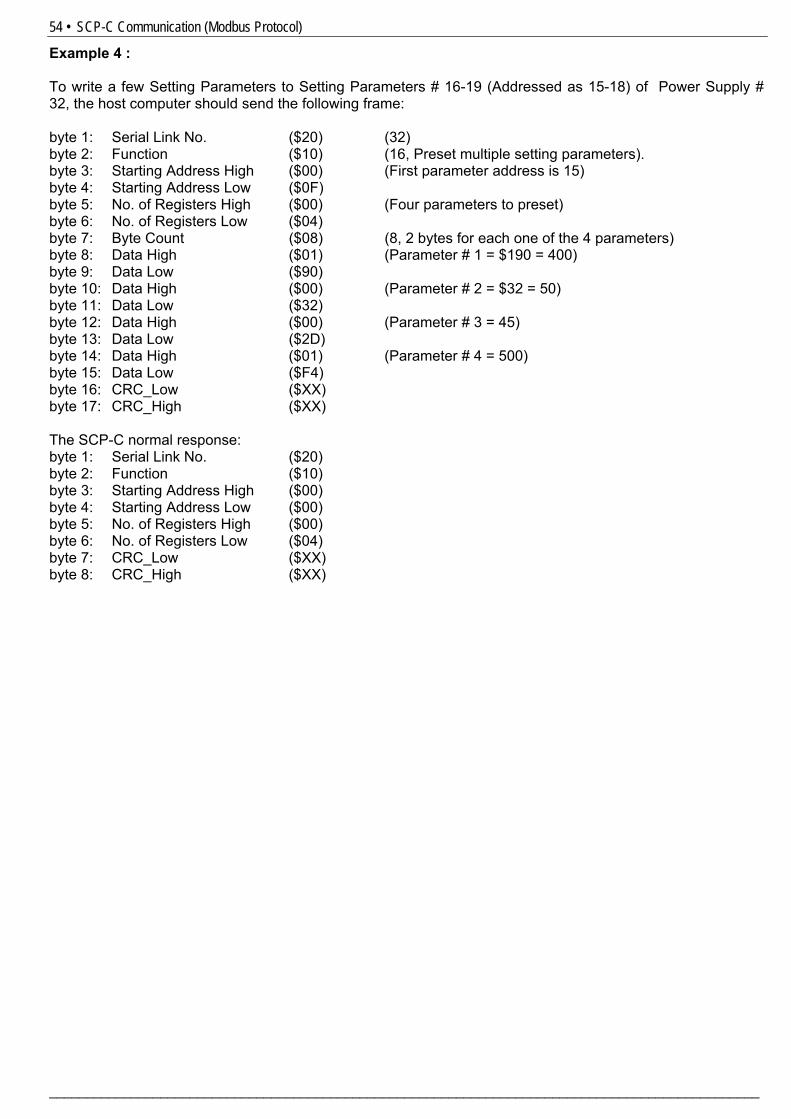
54 • SCP-C Communication (Modbus Protocol)
________________________________________________________________________________________________
Example 4 : To write a few Setting Parameters to Setting Parameters # 16-19 (Addressed as 15-18) of Power Supply # 32, the host computer should send the following frame: byte 1: Serial Link No. ($20) (32) byte 2: Function ($10) (16, Preset multiple setting parameters). byte 3: Starting Address High ($00) (First parameter address is 15) byte 4: Starting Address Low ($0F) byte 5: No. of Registers High ($00) (Four parameters to preset) byte 6: No. of Registers Low ($04) byte 7: Byte Count ($08) (8, 2 bytes for each one of the 4 parameters) byte 8: Data High ($01) (Parameter # 1 = $190 = 400) byte 9: Data Low ($90) byte 10: Data High ($00) (Parameter # 2 = $32 = 50) byte 11: Data Low ($32) byte 12: Data High ($00) (Parameter # 3 = 45) byte 13: Data Low ($2D) byte 14: Data High ($01) (Parameter # 4 = 500) byte 15: Data Low ($F4) byte 16: CRC_Low ($XX) byte 17: CRC_High ($XX) The SCP-C normal response: byte 1: Serial Link No. ($20) byte 2: Function ($10) byte 3: Starting Address High ($00) byte 4: Starting Address Low ($00) byte 5: No. of Registers High ($00) byte 6: No. of Registers Low ($04) byte 7: CRC_Low ($XX) byte 8: CRC_High ($XX)
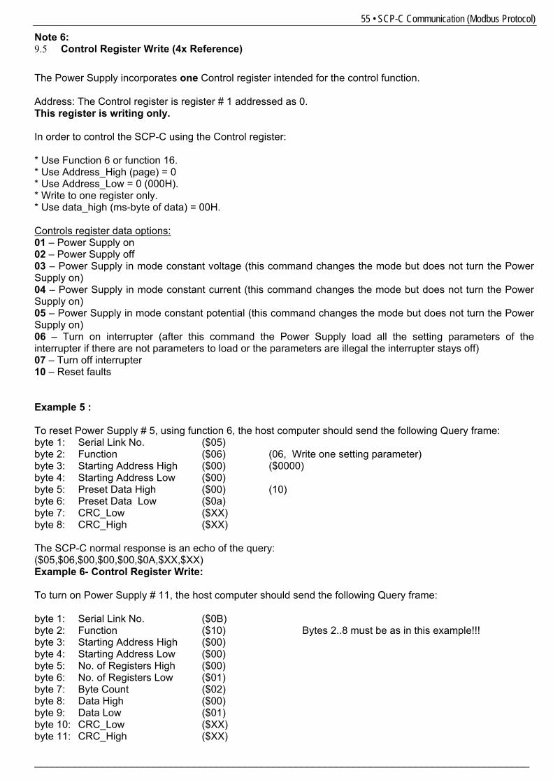
55 • SCP-C Communication (Modbus Protocol)
_______________________________________________________________________________________
Note 6: 9.5 Control Register Write (4x Reference) The Power Supply incorporates one Control register intended for the control function. Address: The Control register is register # 1 addressed as 0. This register is writing only. In order to control the SCP-C using the Control register: * Use Function 6 or function 16. * Use Address_High (page) = 0 * Use Address_Low = 0 (000H). * Write to one register only. * Use data_high (ms-byte of data) = 00H. Controls register data options: 01 – Power Supply on 02 – Power Supply off 03 – Power Supply in mode constant voltage (this command changes the mode but does not turn the Power Supply on) 04 – Power Supply in mode constant current (this command changes the mode but does not turn the Power Supply on) 05 – Power Supply in mode constant potential (this command changes the mode but does not turn the Power Supply on) 06 – Turn on interrupter (after this command the Power Supply load all the setting parameters of the interrupter if there are not parameters to load or the parameters are illegal the interrupter stays off) 07 – Turn off interrupter 10 – Reset faults Example 5 : To reset Power Supply # 5, using function 6, the host computer should send the following Query frame: byte 1: Serial Link No. ($05) byte 2: Function ($06) (06, Write one setting parameter) byte 3: Starting Address High ($00) ($0000) byte 4: Starting Address Low ($00) byte 5: Preset Data High ($00) (10) byte 6: Preset Data Low ($0a) byte 7: CRC_Low ($XX) byte 8: CRC_High ($XX) The SCP-C normal response is an echo of the query: ($05,$06,$00,$00,$00,$0A,$XX,$XX) Example 6- Control Register Write: To turn on Power Supply # 11, the host computer should send the following Query frame: byte 1: Serial Link No. ($0B) byte 2: Function ($10) Bytes 2..8 must be as in this example!!! byte 3: Starting Address High ($00) byte 4: Starting Address Low ($00) byte 5: No. of Registers High ($00) byte 6: No. of Registers Low ($01) byte 7: Byte Count ($02) byte 8: Data High ($00) byte 9: Data Low ($01) byte 10: CRC_Low ($XX) byte 11: CRC_High ($XX)
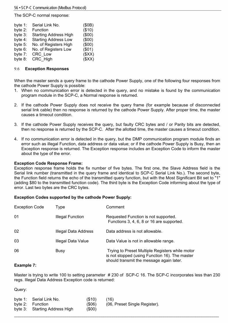
56 • SCP-C Communication (Modbus Protocol)
________________________________________________________________________________________________
The SCP-C normal response: byte 1: Serial Link No. ($0B) byte 2: Function ($10) byte 3: Starting Address High ($00) byte 4: Starting Address Low ($00) byte 5: No. of Registers High ($00) byte 6: No. of Registers Low ($01) byte 7: CRC_Low ($XX) byte 8: CRC_High ($XX) 9.6 Exception Responses When the master sends a query frame to the cathode Power Supply, one of the following four responses from the cathode Power Supply is possible: 1. When no communication error is detected in the query, and no mistake is found by the communication
program module in the SCP-C, a Normal response is returned. 2. If the cathode Power Supply does not receive the query frame (for example because of disconnected
serial link cable) then no response is returned by the cathode Power Supply. After proper time, the master causes a timeout condition.
3. If the cathode Power Supply receives the query, but faulty CRC bytes and / or Parity bits are detected,
then no response is returned by the SCP-C. After the allotted time, the master causes a timeout condition. 4. If no communication error is detected in the query, but the DMP communication program module finds an
error such as illegal Function, data address or data value; or if the cathode Power Supply is Busy, then an Exception response is returned. The Exception response includes an Exception Code to inform the master about the type of the error.
Exception Code Response Frame: Exception response frame holds the fix number of five bytes. The first one, the Slave Address field is the Serial link number (transmitted in the query frame and identical to SCP-C Serial Link No.). The second byte, the Function field returns the echo of the transmitted query function, but with the Most Significant Bit set to "1" (adding $80 to the transmitted function code). The third byte is the Exception Code informing about the type of error. Last two bytes are the CRC bytes. Exception Codes supported by the cathode Power Supply: Exception Code Type Comment 01 Illegal Function Requested Function is not supported. Functions 3, 4, 6, 8 or 16 are supported. 02 Illegal Data Address Data address is not allowable. 03 Illegal Data Value Data Value is not in allowable range. 06 Busy Trying to Preset Multiple Registers while motor
is not stopped (using Function 16). The master should transmit the message again later. Example 7: Master is trying to write 100 to setting parameter # 230 of SCP-C 16. The SCP-C incorporates less than 230 regs. Illegal Data Address Exception code is returned: Query: byte 1: Serial Link No. ($10) (16) byte 2: Function ($06) (06, Preset Single Register). byte 3: Starting Address High ($00)
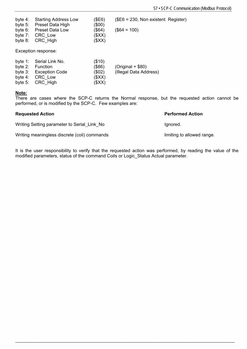
57 • SCP-C Communication (Modbus Protocol)
_______________________________________________________________________________________________
byte 4: Starting Address Low ($E6) ($E6 = 230, Non existent Register) byte 5: Preset Data High ($00) byte 6: Preset Data Low ($64) ($64 = 100) byte 7: CRC_Low ($XX) byte 8: CRC_High ($XX) Exception response: byte 1: Serial Link No. ($10) byte 2: Function ($86) (Original + $80) byte 3: Exception Code ($02) (Illegal Data Address) byte 4: CRC_Low ($XX) byte 5: CRC_High ($XX) Note: There are cases where the SCP-C returns the Normal response, but the requested action cannot be performed, or is modified by the SCP-C. Few examples are: Requested Action Performed Action Writing Setting parameter to Serial_Link_No Ignored. Writing meaningless discrete (coil) commands limiting to allowed range. It is the user responsibility to verify that the requested action was performed, by reading the value of the modified parameters, status of the command Coils or Logic_Status Actual parameter.
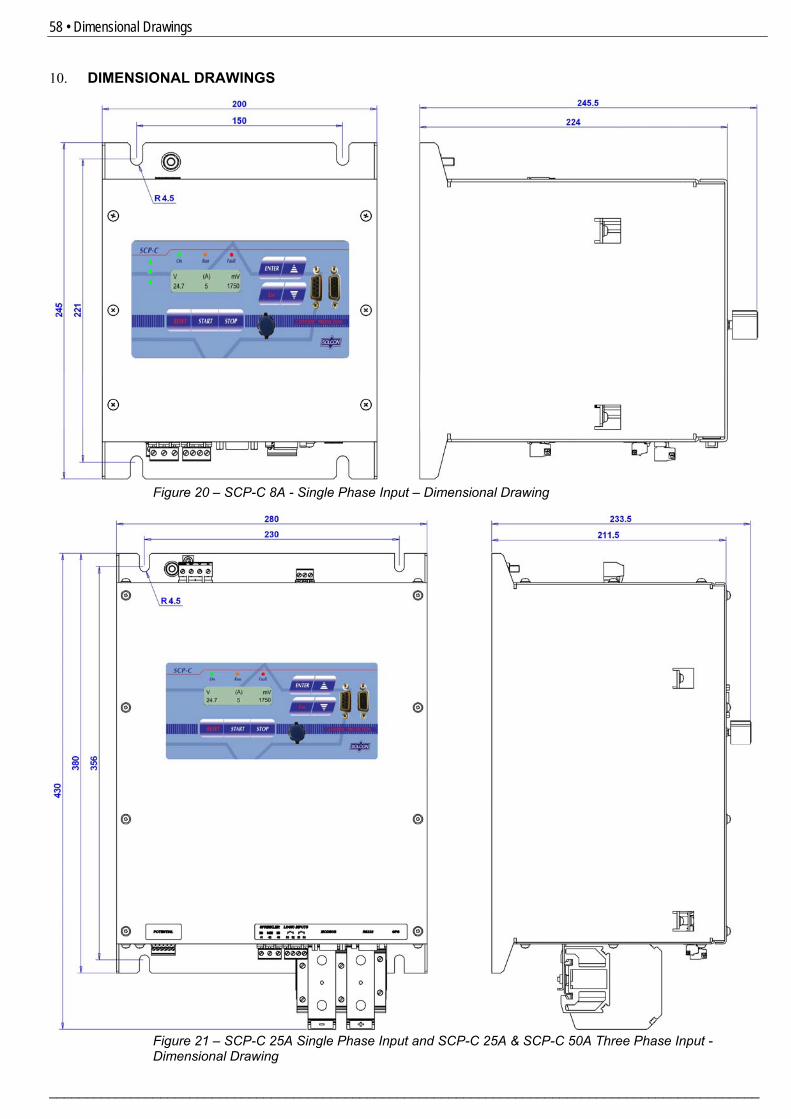
58 • Dimensional Drawings
________________________________________________________________________________________________
10. DIMENSIONAL DRAWINGS
Figure 20 – SCP-C 8A - Single Phase Input – Dimensional Drawing
Figure 21 – SCP-C 25A Single Phase Input and SCP-C 25A & SCP-C 50A Three Phase Input - Dimensional Drawing
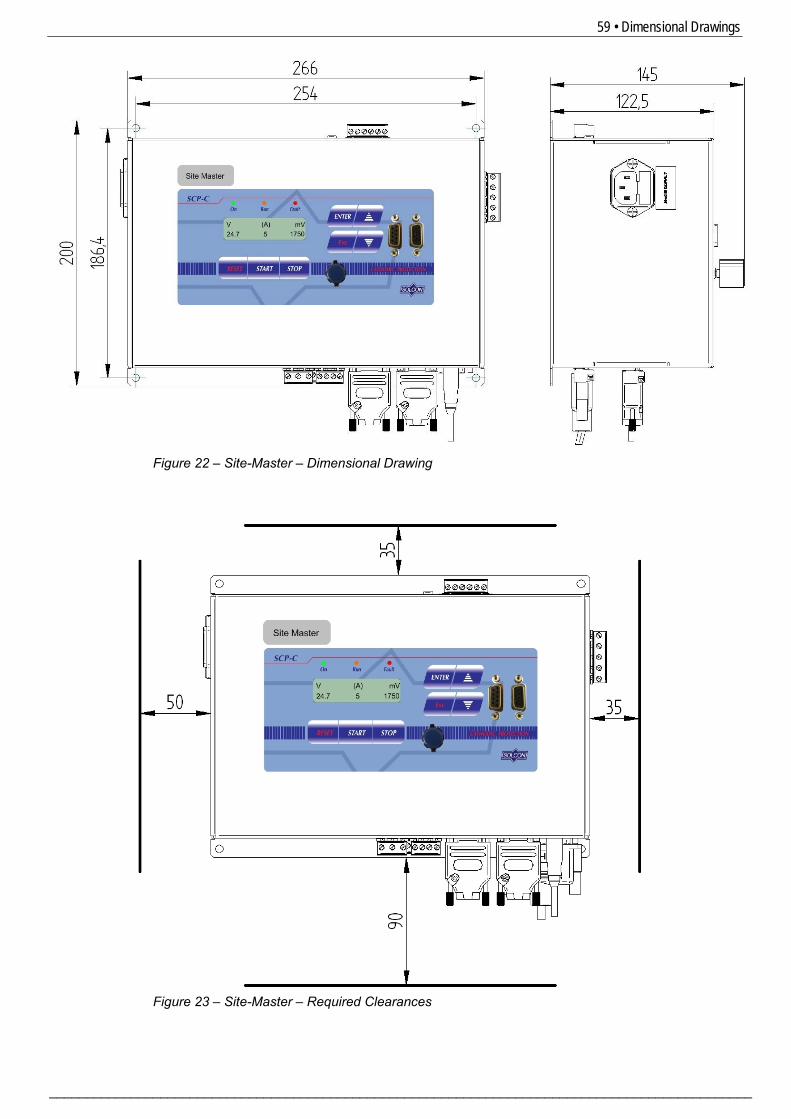
59 • Dimensional Drawings
_______________________________________________________________________________________________
Figure 22 – Site-Master – Dimensional Drawing
Figure 23 – Site-Master – Required Clearances
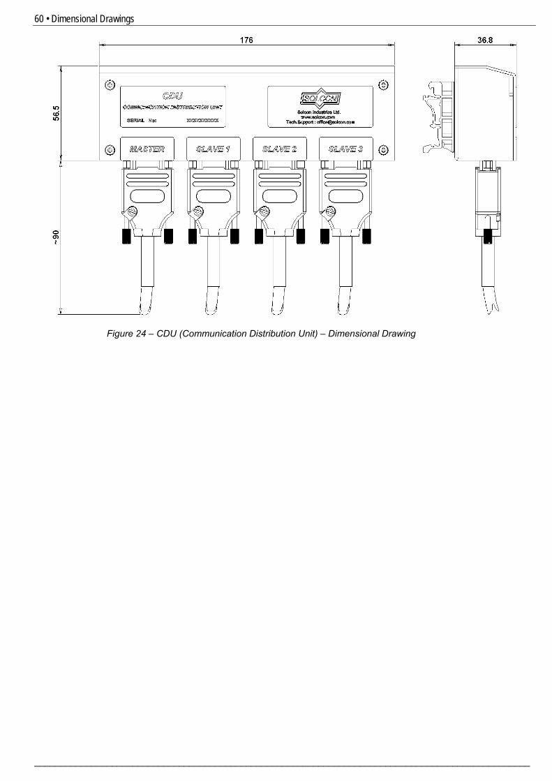
60 • Dimensional Drawings
________________________________________________________________________________________________
Figure 24 – CDU (Communication Distribution Unit) – Dimensional Drawing
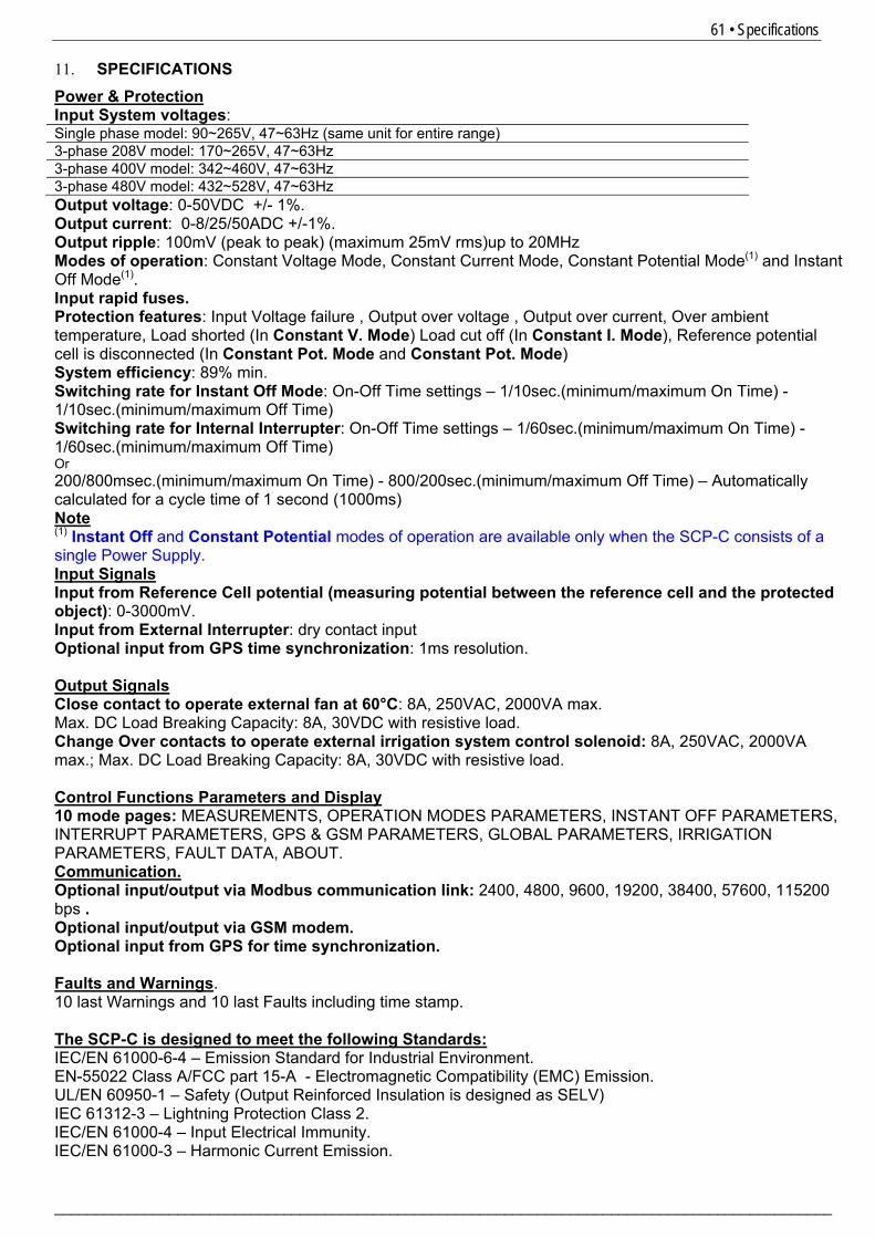
61 • Specifications
_______________________________________________________________________________________________
11. SPECIFICATIONS Power & Protection Input System voltages: Single phase model: 90~265V, 47~63Hz (same unit for entire range) 3-phase 208V model: 170~265V, 47~63Hz 3-phase 400V model: 342~460V, 47~63Hz 3-phase 480V model: 432~528V, 47~63Hz Output voltage: 0-50VDC +/- 1%. Output current: 0-8/25/50ADC +/-1%. Output ripple: 100mV (peak to peak) (maximum 25mV rms)up to 20MHz Modes of operation: Constant Voltage Mode, Constant Current Mode, Constant Potential Mode(1) and Instant Off Mode(1). Input rapid fuses. Protection features: Input Voltage failure , Output over voltage , Output over current, Over ambient temperature, Load shorted (In Constant V. Mode) Load cut off (In Constant I. Mode), Reference potential cell is disconnected (In Constant Pot. Mode and Constant Pot. Mode) System efficiency: 89% min. Switching rate for Instant Off Mode: On-Off Time settings – 1/10sec.(minimum/maximum On Time) - 1/10sec.(minimum/maximum Off Time) Switching rate for Internal Interrupter: On-Off Time settings – 1/60sec.(minimum/maximum On Time) - 1/60sec.(minimum/maximum Off Time) Or 200/800msec.(minimum/maximum On Time) - 800/200sec.(minimum/maximum Off Time) – Automatically calculated for a cycle time of 1 second (1000ms) Note (1) Instant Off and Constant Potential modes of operation are available only when the SCP-C consists of a single Power Supply. Input Signals Input from Reference Cell potential (measuring potential between the reference cell and the protected object): 0-3000mV. Input from External Interrupter: dry contact input Optional input from GPS time synchronization: 1ms resolution. Output Signals Close contact to operate external fan at 60°C: 8A, 250VAC, 2000VA max. Max. DC Load Breaking Capacity: 8A, 30VDC with resistive load. Change Over contacts to operate external irrigation system control solenoid: 8A, 250VAC, 2000VA max.; Max. DC Load Breaking Capacity: 8A, 30VDC with resistive load. Control Functions Parameters and Display 10 mode pages: MEASUREMENTS, OPERATION MODES PARAMETERS, INSTANT OFF PARAMETERS, INTERRUPT PARAMETERS, GPS & GSM PARAMETERS, GLOBAL PARAMETERS, IRRIGATION PARAMETERS, FAULT DATA, ABOUT. Communication. Optional input/output via Modbus communication link: 2400, 4800, 9600, 19200, 38400, 57600, 115200 bps . Optional input/output via GSM modem. Optional input from GPS for time synchronization. Faults and Warnings. 10 last Warnings and 10 last Faults including time stamp. The SCP-C is designed to meet the following Standards: IEC/EN 61000-6-4 – Emission Standard for Industrial Environment. EN-55022 Class A/FCC part 15-A - Electromagnetic Compatibility (EMC) Emission. UL/EN 60950-1 – Safety (Output Reinforced Insulation is designed as SELV) IEC 61312-3 – Lightning Protection Class 2. IEC/EN 61000-4 – Input Electrical Immunity. IEC/EN 61000-3 – Harmonic Current Emission.
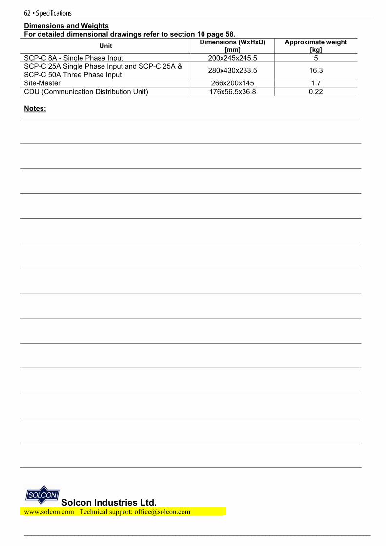
62 • Specifications
________________________________________________________________________________________________
Dimensions and Weights For detailed dimensional drawings refer to section 10 page 58.
Unit Dimensions (WxHxD) [mm]
Approximate weight [kg]
SCP-C 8A - Single Phase Input 200x245x245.5 5 SCP-C 25A Single Phase Input and SCP-C 25A & SCP-C 50A Three Phase Input 280x430x233.5 16.3
Site-Master 266x200x145 1.7 CDU (Communication Distribution Unit) 176x56.5x36.8 0.22 Notes:
Solcon Industries Ltd. 2www.solcon.com Technical support: [email protected]