Embed Size (px)
Citation preview
Available online at www.sciencedirect.com
Physics Procedia 14 (2011) 12–24
1875-3892 © 2011 Published by Elsevier Ltd.doi:10.1016/j.phpro.2011.05.005
9th International Conference on Nano-Molecular Electronics
Cathodic electrodeposition of p-CuSCN nanorod and its dye-sensitized photocathodic property
Lina Sun, Keigo Ichinose, Tomohiro Sekiya, Takashi Sugiura, and Tsukasa Yoshida* Center of Innovative Photovoltaic Systems (CIPS), Environmental and Renewable Energy Systems (ERES) Division, Graduate School of
Engineering, Gifu University, Yanagido 1-1, Gifu 501-1193, Gifu, Japan
Abstract
Mechanism of cathodic electrodeposition of CuSCN from ethanolic solutions containing Cu2+ and SCN- was studied in detail. Job’s plot for the absorption spectra of mixed solution in various Cu2+ : SCN- ratios have revealed the presence of [Cu(SCN)2]0 as a soluble species responsible to the electrode process in SCN- rich solutions. From Levich analysis of diffusion limited current employing a rotating disc electrode (RDE), diffusion coefficients of 5.2 × 10⁻⁶ cm2 s-1 and 3.0 × 10⁻⁶ cm2 s-1 in ethanol at 298 K were determined for [Cu(SCN)2]0 and [Cu(SCN)]+, respectively. Morphology as well as crystallographic orientation of the product films significantly changed by the composition of the electrolytic baths. When the bath contains excess of Cu2+ and mixed solvent up to 50% ethanol content to water was used, strong anisotropic crystal growth along the c-axis was observed. When electrolysis was carried out under stationary conditions, the nanorod structures in high aspect ratios could be obtained, due to the limited transport of the active species to the tip of the rods. When rhodamine B was adsorbed onto such CuSCN as a sensitizer, dye-sensitized photocathodic current was observed with an incident photon to current conversion efficiency (IPCE) of 4.4% at the absorption maximum, suggesting its usefulness as the hole conducting electrode in construction of nanostructured solar cells. © 2010 Published by Elsevier B.V. Keyword; CuSCN, nanorod, electrodeposition, mass transport, dye-sensitization
1. Introduction
Nanostructured solar cells employing hybrid materials of organic and inorganic semiconductors are emerging as the candidates of cost-effective photovoltaic systems [1-6]. High efficiencies are achieved by dye-sensitized solar cells (DSSCs) employing nanostructured porous photoelectrodes of n-type metal oxides such as TiO2 and ZnO, sensitized by photosensitizer dye molecules that is in contact with a liquid electrolyte solution containing I-/I3
- redox couple that serves as a hole transporting material [4,5]. However, the use of the electrolyte solution is known to become a problem for long term stability of the device due to the difficulties of the sealing. In order to overcome this problem, substitution of hole transporting material with a solid p-type semiconductor such as CuSCN [6] and CuI [2,3] has been attempted. These materials are also used as hole transporting materials in extremely thin absorber
* Corresponding author. Tel.: +81-58-293-2593; fax: +81-58-293-2594. E-mail address: [email protected]
Open access under CC BY-NC-ND license.
Open access under CC BY-NC-ND license.
Lina Sun et al. / Physics Procedia 14 (2011) 12–24 13
(ETA) solar cells using nanostructured electron conducting electrode and inorganic quantum dots as the light absorber [7,8]. They are typically filled into the gap of the sensitized electron conducting electrode by casting their solution and drying. Imperfect filling of the pores often becomes a limiting factor for the efficiencies of such devices, especially when too narrow pores are formed.
Crystalline thin films of CuSCN can be electrodeposited directly from aqueous or ethanolic solution of Cu2+ and SCN- [9-12]. CuSCN is relatively stable compared to CuI. We have previously shown that certain dye molecules having thiocyanate and amino groups can be hybridized with CuSCN by simply adding them into the electrolytic bath [5,13]. These groups are categorized as soft Lewis basic according to the HSAB (Hard and Soft, Acid and Base) principle and thus form stable coordination to soft acidic Cu(I) sites of CuSCN. The loading of dye molecules to CuSCN leads to a formation of unique nanostructures, since they act as structure directing agents (SDAs) for the crystal growth. The loaded dyes were able to inject holes from their photoexcited state to CuSCN to perform as sensitized photocathode [5]. Such a system can be useful for construction of tandem solar cells connecting dye-sensitized photoanode and photocathode in series for increased voltage [14,15]. It is also important to understand the chemistry between the dye molecules and CuSCN with respect to efficiency of charge separation, since not only the efficiency of electron injection to the n-type electrode but also hole injection to the p-type material matters for the efficiency of solid-state DSSCs. In this regard, there have been pioneering studies for cathodic dye-sensitization of CuSCN by Tennakone [11] and O’Regan [12].
In this paper, we have studied the mechanism of electrodeposition of CuSCN through electrochemical analysis under diffusion limited regime employing a rotating disc electrode (RDE). Complexes between Cu2+ and SCN- responsible to the electrode process were identified, and their diffusion coefficients were analyzed. The composition of the bath turned out to influence strongly the crystallographic orientation and morphology of the products. Through these studies, conditions to obtain CuSCN in nanorod structure were identified. Electrochemical and chemical deposition of highly oriented crystalline ZnO nanorod has previously been reported and used in construction of nanostructured solar cells [16,17]. The CuSCN nanorod obtained in this study can be seen as the counter part as it offers new possibilities to fabricate nanostructured solar cells in reversed process, starting from the formation of nanostructured p-type electrode. Its dye-sensitized photocathodic property has also been studied in this paper.
2. Experimental
Fluorine doped SnO2 (FTO) coated glass (1.1 mm thick, 10 / , Asahi Glass) sheets cut into 2.5 cm square were subsequently cleaned ultrasonically in acetone, 2-propanol, detergent, and water. They were activated in a 45% HNO3 for 2 min and finally rinsed with distilled water before they were attached to the RDE system for the electrochemical experiments. Cu(ClO4)2 (Aldrich), LiSCN (Kishida), LiClO4 (Aldrich), rhodamine B chloride (Tokyo Kasei) and methylviologen dichloride (Aldrich) were commercially available purest grade and used as received.
Mixed solutions of Cu(ClO4)2 and LiSCN in various ratios, while keeping their total concentration constant, were prepared in ethanol (Wako) and their absorption spectra were measured in a quartz cell with 1 cm optical path length using a HITACHI U-4100 spectrophotometer. The sample solutions for electrochemical analysis and thin film electrodeposition also contained Cu(ClO4)2 and LiSCN in various ratios together with 0.1 M LiClO4 as a supporting electrolyte. They were deaerated by bubbling Ar gas.
Electrochemical analysis and thin film electrodeposition were performed using Universal Solar Cell RDE-1 system specially developed for thin film electrodeposition purposes. It permits use of optically transparent conductive substrates by making electrical contact from the conductive front surface of the substrate. The temperature of the sample solution was maintained at 25°C by a thermostat. The active area of the electrode was regulated to 3.8 cm2 (22 mm in diameter) by a masking tape. The electrodeposited film samples can be detached from the electrode holder for analysis of the product films. Pt wire and Ag/AgCl electrode (Radiometer) were used as the counter and reference electrodes, respectively. Hokuto Denko HSV-100 voltammetric tool was used for potential control and current monitoring of all electrochemical experiments. Rotation speed of the RDE was varied between 100 and 800 rpm and the potential was scanned at 5 mV s-1 for Levich analysis of the diffusion limited current. Thin film electrodeposition was carried out potentiostatically by applying sufficiently negative
14 Lina Sun et al. / Physics Procedia 14 (2011) 12–24
potentials between +0.3 and -0.2 V (vs. Ag/AgCl) to achieve film growth under diffusion limited conditions but avoiding electrodeposition of metallic Cu, depending on the composition of the sample solution.
The electrodeposited film samples were observed for its surface and cross-section on a HITACHI S-4800 field-emission scanning electron microscope (FE-SEM). Samples of CuSCN nanorod was scratched off from the substrate and taken onto a micro grid for observation by a transmission electron microscope (TEM) on a HITACHI H-8100. X-ray diffraction (XRD) patterns of the films were measured on a Rigaku RINT Ultima-III using Cu K radiation.
The FTO glass substrate with electrodeposited CuSCN thin film was cut into 4 equivalent pieces in 12.5 mm square size, soaked and refluxed in a 1 mM ethanolic solution of rhodamine B chloride for 1 h for sensitization. A Cu wire was connected to the bare part of the FTO using Ag-epoxy for electrical contact and insulated by applying silicone glue. The effective area of the electrode to be in contact with the electrolyte solution was measured by a digital microscope (Keyence) as 0.29 cm2. This photoelectrode was put in a glass cell equipped with an optical window together with Pt foil counter and a saturated calomel reference electrodes. An aqueous solution containing 0.1 M methylviologen chloride and 0.1 M KCl deaerated by Ar was used as the electrolyte. Light was illuminated through the optical window, generated by a 500 W Xe lamp filtered for > 420 nm (intensity = 100 mW cm-2) for I-V measurements. Monochromatic light was generated by a monochrometer (Nikon) and the light intensity was measured for each wavelength by using a thermopile (Eppley) for calculation of photonflux for photocurrent action spectrum.
3. Results and Discussion
3.1 Formation of complexes between Cu2+ and SCN- and their electrochemical reduction
Cathodic electrodeposition of CuSCN was typically carried out in aqueous [9,10] and ethanolic [11,12] solutions containing Cu2+ and SCN- ions. In our previous study for the aqueous system, we have identified that the active species for the electrode reaction is a 1 to 1 complex between Cu2+ and SCN- [9].
[Cu(SCN)]+ + e- CuSCN (1) Levich analysis employing an RDE revealed a diffusion coefficient of this complex in water as D = 1.05 × 10⁻⁵ (cm s-1) at 298 K.
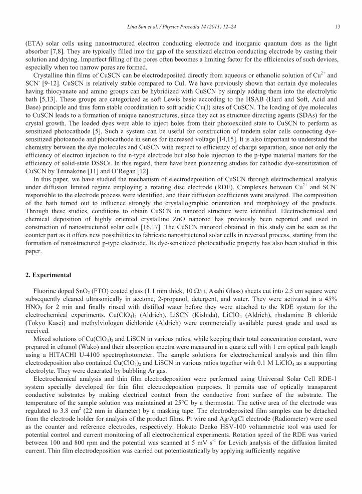
Mixed solutions were prepared in ethanol for various Cu2+ : SCN- ratios, while keeping their total concentration to 1 mM. Their absorption spectra are shown in Fig. 1(a). While the solution of Cu(ClO4)2 shows a weak and broad absorption above 600 nm associated with the d-d transition of Cu2+, the mixed solutions show intense absorption peaks around 400 nm due to coordination of SCN- to Cu2+. The color of the solution turns from blue to yellow or greenish yellow. This peak of the (Ligand to Metal Charge Transfer) LMCT band of the complex changes from 412
Fig. 1 (a) Absorption spectra of ethanolic solutions in which total concentration, [Cu2+] + [SCN-] was fixed to 1 mM, while their ratio was varied. (b) Job’s plot drawn from the absorption maxima in (a). The peak wavelength for solutions with [Cu2+] excess is around 412 nm, whereas those with [SCN-] excess is around 398 nm.
Lina Sun et al. / Physics Procedia 14 (2011) 12–24 15
nm for Cu2+ rich solutions to 398 nm for those in excess of SCN-. Careful comparison of the spectra in Fig. 1(a) also reveals that the maximum absorption is not reached for the 1 : 1 mixture but for those with slightly higher amount of SCN-. Most likely, such a transition is caused by the change of the dominant complex species from singly coordinated [Cu(SCN)]+ in the Cu2+ rich solutions to doubly coordinated [Cu(SCN)2]0 in the SCN- rich solutions. Job’s plot is drawn in Fig. 1(b) by tracking absorbance of the mixed solutions at the maxima disregarding the shift of the peak wavelength. Very nice fittings of straight lines from both ends of the molar fraction of Cu2+ can be drawn and they cross at the ratio of Cu2+ : SCN- = 1 : 2. It evidently speaks for the formation of [Cu(SCN)2]0 complex as the predominant species unlike the case of aqueous solution for which Job’s plot indicated formation of only [Cu(SCN)]+. Formation of [Cu(SCN)2]0 species in organic medium has actually been suggested in literature [11]. The linear change of absorbance despite of the shift of the peak wavelength indicate that the absorbance is simply proportional to the number of bond between Cu2+ and SCN- irrespective of the structure of the complex. From the absorbance of the crossing point, molar absorption coefficient of 1,350 M-1 cm-1 is determined for [Cu(SCN)2]0, close to the value (1,170 M-1 cm-1) reported for the same species in dioxane / water = 50 / 50 mixture [18]. The value for [Cu(SCN)]+ in ethanol should then be half of this value, but it is still much larger than that found in water (184 M-1 cm-1) [9].
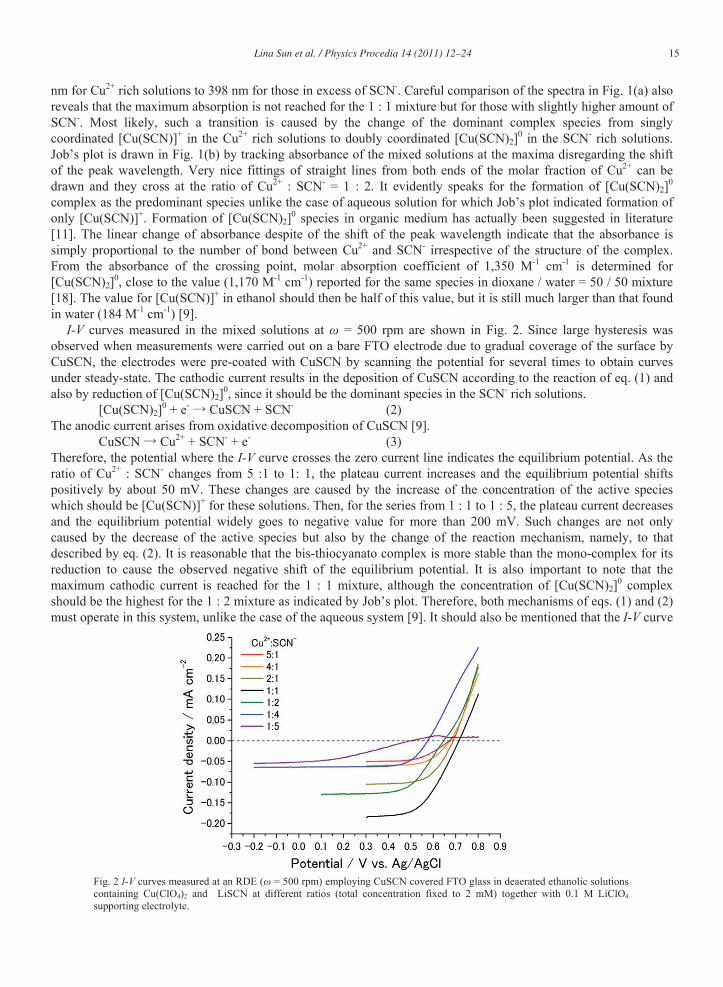
I-V curves measured in the mixed solutions at = 500 rpm are shown in Fig. 2. Since large hysteresis was observed when measurements were carried out on a bare FTO electrode due to gradual coverage of the surface by CuSCN, the electrodes were pre-coated with CuSCN by scanning the potential for several times to obtain curves under steady-state. The cathodic current results in the deposition of CuSCN according to the reaction of eq. (1) and also by reduction of [Cu(SCN)2]0, since it should be the dominant species in the SCN- rich solutions.
[Cu(SCN)2]0 + e- CuSCN + SCN- (2) The anodic current arises from oxidative decomposition of CuSCN [9].
CuSCN Cu2+ + SCN- + e- (3) Therefore, the potential where the I-V curve crosses the zero current line indicates the equilibrium potential. As the ratio of Cu2+ : SCN- changes from 5 :1 to 1: 1, the plateau current increases and the equilibrium potential shifts positively by about 50 mV. These changes are caused by the increase of the concentration of the active species which should be [Cu(SCN)]+ for these solutions. Then, for the series from 1 : 1 to 1 : 5, the plateau current decreases and the equilibrium potential widely goes to negative value for more than 200 mV. Such changes are not only caused by the decrease of the active species but also by the change of the reaction mechanism, namely, to that described by eq. (2). It is reasonable that the bis-thiocyanato complex is more stable than the mono-complex for its reduction to cause the observed negative shift of the equilibrium potential. It is also important to note that the maximum cathodic current is reached for the 1 : 1 mixture, although the concentration of [Cu(SCN)2]0 complex should be the highest for the 1 : 2 mixture as indicated by Job’s plot. Therefore, both mechanisms of eqs. (1) and (2) must operate in this system, unlike the case of the aqueous system [9]. It should also be mentioned that the I-V curve
Fig. 2 I-V curves measured at an RDE ( = 500 rpm) employing CuSCN covered FTO glass in deaerated ethanolic solutions containing Cu(ClO4)2 and LiSCN at different ratios (total concentration fixed to 2 mM) together with 0.1 M LiClO4 supporting electrolyte.
16 Lina Sun et al. / Physics Procedia 14 (2011) 12–24
for the 1 : 5 mixture shows only a very small anodic current. As it is shown later in this paper, the formation of CuSCN becomes inefficient when the solution contains an extreme excess of SCN-. It is likely that the reduction of [Cu(SCN)2]0 does not result in its decomposition to yield CuSCN but simply ends up as a soluble product due to the increased stability of coordination.
[Cu(SCN)2]0 + e- [Cu(SCN)2]- (4) Such a reaction was suggested earlier in excess of SCN- to decrease the efficiency of CuSCN precipitation [19].
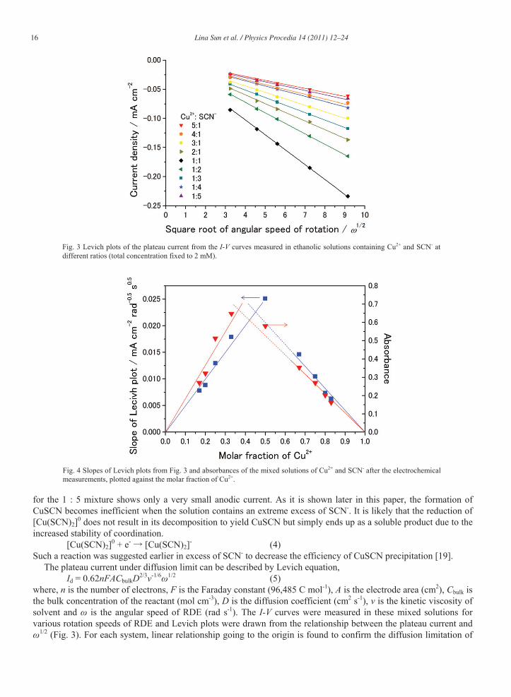
The plateau current under diffusion limit can be described by Levich equation, Id = 0.62nFACbulkD2/3 -1/6 1/2 (5)
where, n is the number of electrons, F is the Faraday constant (96,485 C mol-1), A is the electrode area (cm2), Cbulk is the bulk concentration of the reactant (mol cm-3), D is the diffusion coefficient (cm2 s-1), is the kinetic viscosity of solvent and is the angular speed of RDE (rad s-1). The I-V curves were measured in these mixed solutions for various rotation speeds of RDE and Levich plots were drawn from the relationship between the plateau current and
1/2 (Fig. 3). For each system, linear relationship going to the origin is found to confirm the diffusion limitation of
Fig. 3 Levich plots of the plateau current from the I-V curves measured in ethanolic solutions containing Cu2+ and SCN- at different ratios (total concentration fixed to 2 mM).
Fig. 4 Slopes of Levich plots from Fig. 3 and absorbances of the mixed solutions of Cu2+ and SCN- after the electrochemical measurements, plotted against the molar fraction of Cu2+.
Lina Sun et al. / Physics Procedia 14 (2011) 12–24 17
the reaction. It is immediately recognized that the current change is not symmetrical to the change of the Cu2+ : SCN- ratio. The current measured in the solutions in excess of SCN- is always higher than that in the solution of counter composition reversing the Cu2+ : SCN- ratio. In order to clarify the relationship, the slopes of Levich plots are plotted against molar fraction of Cu2+ in Fig. 4. In the same figure are also plotted the absorbance of the mixed solution after the electrochemical measurements in order to take into account the decrease of concentration of active species by electrochemical reactions and also by chemical decomposition of the complex that became rapid in the SCN- rich solutions, especially when the total concentration of Cu2+ and SCN- was high. The maximum absorbance occurs approximately in the 1 : 2 composition, same as that for the fresh solutions (Fig. 1(a)), although the crossing point of the linear fits from both ends slightly moved to Cu2+ fraction = 0.37 due to uneven consumption of the complexes. Unlike the absorbance, the slope peaks at the 1 : 1 composition. From both ends of Cu2+ fraction, the plots approximately align on straight lines. The plot for the 1 : 1 composition seems to stay on the straight line drawn from the SCN- rich side. Linear fits were calculated for these two groups. Somewhat higher slope is found for the SCN- rich side than the Cu2+ rich, so that the crossing point appears at the Cu2+ fraction = 0.45. Converting the linear fits for absorbance to concentration of the active species, comparison of the slopes between the fits for the concentration and the for the slope of Levich plot can yield diffusion coefficients of the active species. Assuming that the active species responsible to the electrode process is [Cu(SCN)2]0 for the SCN- rich compositions and [Cu(SCN)]+ for the Cu2+ rich, and taking the value of kinetic viscosity of ethanol at 298 K from literature ( = 0.010 cm s-1 [20]), D = 5.2 × 10⁻⁶ cm2 s-1 and 3.0 × 10⁻⁶ cm2 s-1 were determined for [Cu(SCN)2]0 and [Cu(SCN)]+, respectively. These values are clearly smaller than that determined for [Cu(SCN)]+ in aqueous solution [9]. Somewhat larger value for [Cu(SCN)2]0 is reasoned by the decreased ionic affinity with the medium. 3.2 Electrodeposition of CuSCN from ethanolic solutions
Thin films of CuSCN were electrodeposited from ethanolic solutions containing Cu(ClO4)2 and LiSCN at various ratios. Since the potentials to reach diffusion limit varies depending on the composition of the solution, different but sufficiently negative potentials were applied to electrodeposit films under diffusion limitation. Also, the electrolysis was carried out for different periods, because the concentration of the active species vary, thus varying the rate of the film growth.
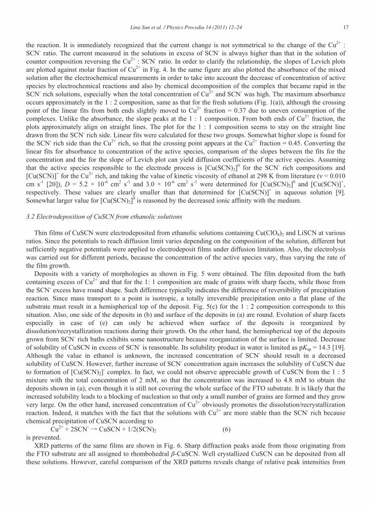
Deposits with a variety of morphologies as shown in Fig. 5 were obtained. The film deposited from the bath containing excess of Cu2+ and that for the 1: 1 composition are made of grains with sharp facets, while those from the SCN- excess have round shape. Such difference typically indicates the difference of reversibility of precipitation reaction. Since mass transport to a point is isotropic, a totally irreversible precipitation onto a flat plane of the substrate must result in a hemispherical top of the deposit. Fig. 5(c) for the 1 : 2 composition corresponds to this situation. Also, one side of the deposits in (b) and surface of the deposits in (a) are round. Evolution of sharp facets especially in case of (e) can only be achieved when surface of the deposits is reorganized by dissolution/recrystallization reactions during their growth. On the other hand, the hemispherical top of the deposits grown from SCN- rich baths exhibits some nanostructure because reorganization of the surface is limited. Decrease of solubility of CuSCN in excess of SCN- is reasonable. Its solubility product in water is limited as pKsp = 14.3 [19]. Although the value in ethanol is unknown, the increased concentration of SCN- should result in a decreased solubility of CuSCN. However, further increase of SCN- concentration again increases the solubility of CuSCN due to formation of [Cu(SCN)2]- complex. In fact, we could not observe appreciable growth of CuSCN from the 1 : 5 mixture with the total concentration of 2 mM, so that the concentration was increased to 4.8 mM to obtain the deposits shown in (a), even though it is still not covering the whole surface of the FTO substrate. It is likely that the increased solubility leads to a blocking of nucleation so that only a small number of grains are formed and they grow very large. On the other hand, increased concentration of Cu2+ obviously promotes the dissolution/recrystallization reaction. Indeed, it matches with the fact that the solutions with Cu2+ are more stable than the SCN- rich because chemical precipitation of CuSCN according to
Cu2+ + 2SCN- CuSCN + 1/2(SCN)2 (6) is prevented.
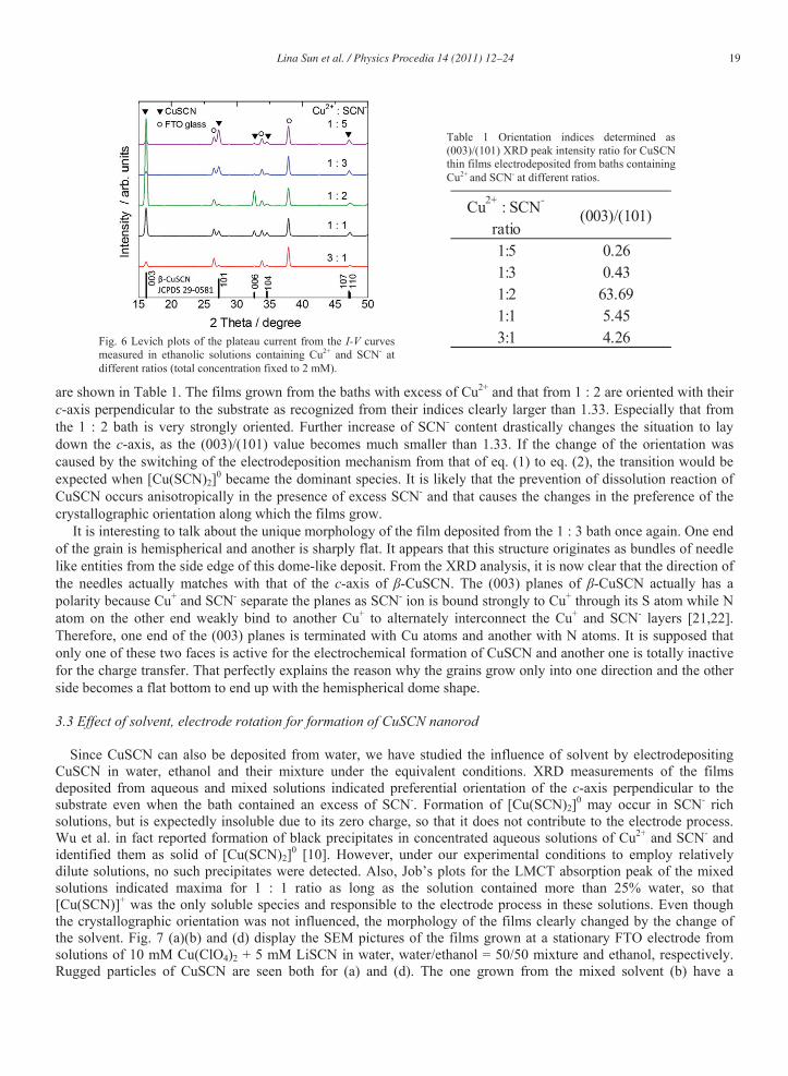
XRD patterns of the same films are shown in Fig. 6. Sharp diffraction peaks aside from those originating from the FTO substrate are all assigned to rhombohedral -CuSCN. Well crystallized CuSCN can be deposited from all these solutions. However, careful comparison of the XRD patterns reveals change of relative peak intensities from
18 Lina Sun et al. / Physics Procedia 14 (2011) 12–24
Fig. 5 SEM photographs for surface (left) and cross-section (right) of CuSCN thin films electrodeposited from ethanolic solutions containing Cu2+ and SCN- in ratios of (a) 1:5, (b) 1:3, (c) 1:2, (d) 1:1 and (e) 3:1 with their total concentration of 2 mM except for (a) (4.8 mM). Deposition was carried out under diffusion limited conditions at -0.2 V (a) 0 V (b,c), +0.3 V (d,e), = 800 rpm and for 60 min (a), 50 min (b), 40 min (c), 20 min (d,e).
film to film. Change of crystallographic orientation has been evaluated by calculating the peak ratio of (003)/(101) (which should be 1.33 from the powder diffraction standard). While (003) planes are vertical to the c-axis of -CuSCN, (101) planes are near parallel with slight tilting of 11.48° with respect to the c-axis, so that the change of this ratio approximately indicates whether the c-axis is perpendicular or horizontal to the substrate plane. The results
Lina Sun et al. / Physics Procedia 14 (2011) 12–24 19
are shown in Table 1. The films grown from the baths with excess of Cu2+ and that from 1 : 2 are oriented with their c-axis perpendicular to the substrate as recognized from their indices clearly larger than 1.33. Especially that from the 1 : 2 bath is very strongly oriented. Further increase of SCN- content drastically changes the situation to lay down the c-axis, as the (003)/(101) value becomes much smaller than 1.33. If the change of the orientation was caused by the switching of the electrodeposition mechanism from that of eq. (1) to eq. (2), the transition would be expected when [Cu(SCN)2]0 became the dominant species. It is likely that the prevention of dissolution reaction of CuSCN occurs anisotropically in the presence of excess SCN- and that causes the changes in the preference of the crystallographic orientation along which the films grow.
It is interesting to talk about the unique morphology of the film deposited from the 1 : 3 bath once again. One end of the grain is hemispherical and another is sharply flat. It appears that this structure originates as bundles of needle like entities from the side edge of this dome-like deposit. From the XRD analysis, it is now clear that the direction of the needles actually matches with that of the c-axis of -CuSCN. The (003) planes of -CuSCN actually has a polarity because Cu+ and SCN- separate the planes as SCN- ion is bound strongly to Cu+ through its S atom while N atom on the other end weakly bind to another Cu+ to alternately interconnect the Cu+ and SCN- layers [21,22]. Therefore, one end of the (003) planes is terminated with Cu atoms and another with N atoms. It is supposed that only one of these two faces is active for the electrochemical formation of CuSCN and another one is totally inactive for the charge transfer. That perfectly explains the reason why the grains grow only into one direction and the other side becomes a flat bottom to end up with the hemispherical dome shape. 3.3 Effect of solvent, electrode rotation for formation of CuSCN nanorod
Since CuSCN can also be deposited from water, we have studied the influence of solvent by electrodepositing
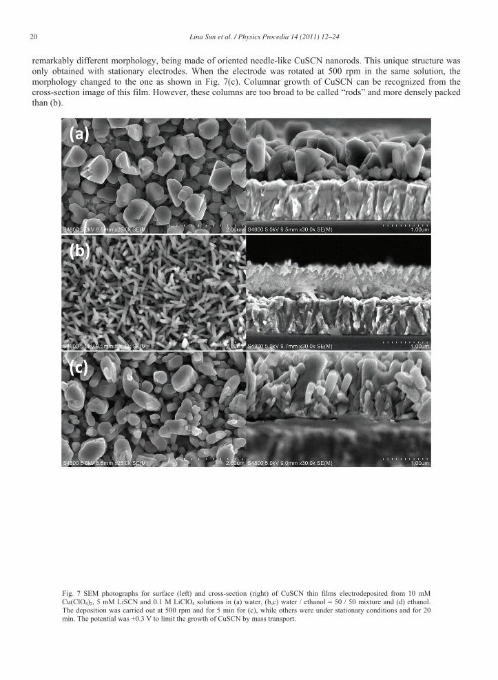
CuSCN in water, ethanol and their mixture under the equivalent conditions. XRD measurements of the films deposited from aqueous and mixed solutions indicated preferential orientation of the c-axis perpendicular to the substrate even when the bath contained an excess of SCN-. Formation of [Cu(SCN)2]0 may occur in SCN- rich solutions, but is expectedly insoluble due to its zero charge, so that it does not contribute to the electrode process. Wu et al. in fact reported formation of black precipitates in concentrated aqueous solutions of Cu2+ and SCN- and identified them as solid of [Cu(SCN)2]0 [10]. However, under our experimental conditions to employ relatively dilute solutions, no such precipitates were detected. Also, Job’s plots for the LMCT absorption peak of the mixed solutions indicated maxima for 1 : 1 ratio as long as the solution contained more than 25% water, so that [Cu(SCN)]+ was the only soluble species and responsible to the electrode process in these solutions. Even though the crystallographic orientation was not influenced, the morphology of the films clearly changed by the change of the solvent. Fig. 7 (a)(b) and (d) display the SEM pictures of the films grown at a stationary FTO electrode from solutions of 10 mM Cu(ClO4)2 + 5 mM LiSCN in water, water/ethanol = 50/50 mixture and ethanol, respectively. Rugged particles of CuSCN are seen both for (a) and (d). The one grown from the mixed solvent (b) have a
Fig. 6 Levich plots of the plateau current from the I-V curves measured in ethanolic solutions containing Cu2+ and SCN- at different ratios (total concentration fixed to 2 mM).
Cu2+ : SCN-
ratio(003)/(101)
1:5 0.261:3 0.431:2 63.691:1 5.453:1 4.26
Table 1 Orientation indices determined as (003)/(101) XRD peak intensity ratio for CuSCN thin films electrodeposited from baths containing Cu2+ and SCN- at different ratios.
20 Lina Sun et al. / Physics Procedia 14 (2011) 12–24
Fig. 7 SEM photographs for surface (left) and cross-section (right) of CuSCN thin films electrodeposited from 10 mM Cu(ClO4)2, 5 mM LiSCN and 0.1 M LiClO4 solutions in (a) water, (b,c) water / ethanol = 50 / 50 mixture and (d) ethanol. The deposition was carried out at 500 rpm and for 5 min for (c), while others were under stationary conditions and for 20 min. The potential was +0.3 V to limit the growth of CuSCN by mass transport.
remarkably different morphology, being made of oriented needle-like CuSCN nanorods. This unique structure was only obtained with stationary electrodes. When the electrode was rotated at 500 rpm in the same solution, the morphology changed to the one as shown in Fig. 7(c). Columnar growth of CuSCN can be recognized from the cross-section image of this film. However, these columns are too broad to be called “rods” and more densely packed than (b).
Lina Sun et al. / Physics Procedia 14 (2011) 12–24 21
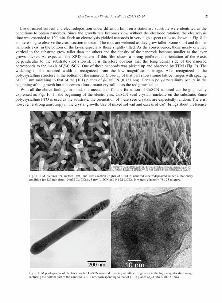
Fig. 8 SEM pictures for surface (left) and cross-section (right) of CuSCN nanorod electrodeposited under a stationary condition for 120 min from 10 mM Cu(ClO4)2, 5 mM LiSCN and 0.1 M LiClO4 in water / ethanol = 75 / 25 mixture.
Fig. 9 TEM photographs of electrodeposited CuSCN nanorod. Spacing of lattice fringe seen in the high magnification image capturing the bottom part of the nanorod is 0.33 nm, corresponding to that of (101) planes of -CuSCN (0.327 nm).
B Use of mixed solvent and electrodeposition under diffusion limit on a stationary substrate were identified as the conditions to obtain nanorods. Since the growth rate becomes slow without the electrode rotation, the electrolysis time was extended to 120 min. Such an electrolysis yielded nanorods in very high aspect ratios as shown in Fig. 8. It is interesting to observe the cross-section in detail. The rods are widened as they grow taller. Some short and thinner nanorods exist in the bottom of the layer, especially those slightly tilted. As the consequence, those nicely oriented vertical to the substrate grow taller than the others and the density of the nanorods become smaller as the layer grows thicker. As expected, the XRD pattern of this film shows a strong preferential orientation of the c-axis perpendicular to the substrate (not shown). It is therefore obvious that the longitudinal side of the nanorod corresponds to the c-axis of -CuSCN. One of these nanorods was picked up and observed by TEM (Fig. 9). The widening of the nanorod width is recognized from the low magnification image. Also recognized is the polycrystalline structure at the bottom of the nanorod. Close-up of that part shows some lattice fringes with spacing of 0.33 nm matching to that of the (101) planes of -CuSCN (0.327 nm). Certain poly-crystallinity occurs in the beginning of the growth but it becomes almost mono-crystalline as the rod grows taller.
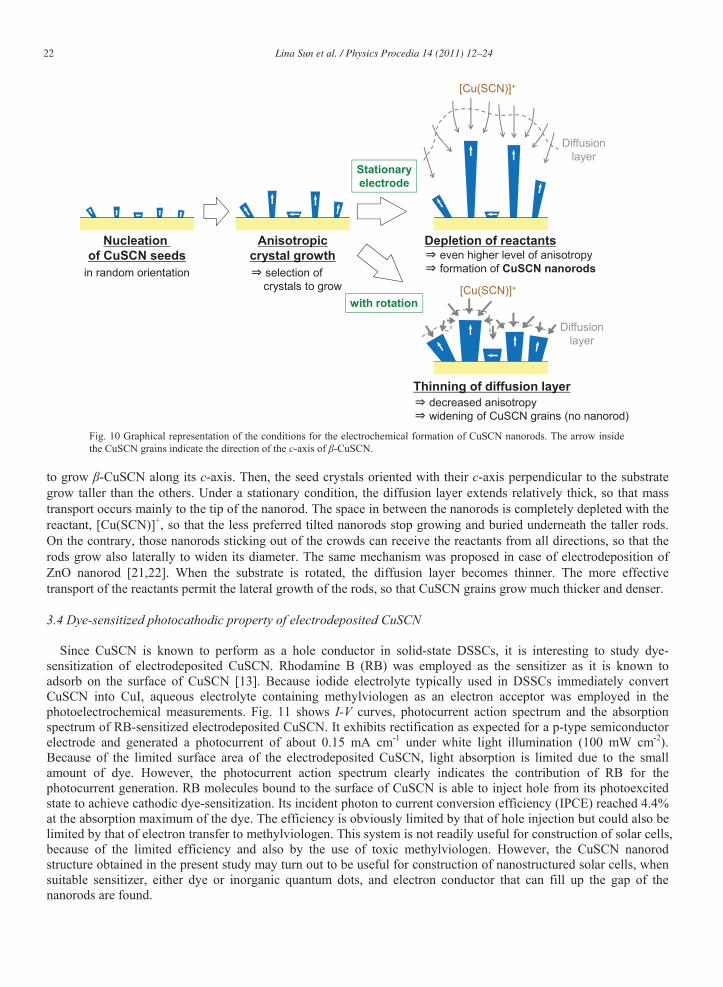
With all the above findings in mind, the mechanism for the formation of CuSCN nanorod can be graphically expressed as Fig. 10. In the beginning of the electrolysis, CuSCN seed crystals nucleate on the substrate. Since polycrystalline FTO is used as the substrate, the orientation of these seed crystals are expectedly random. There is, however, a strong anisotropy in the crystal growth. Use of mixed solvent and excess of Cu2+ brings about preference
22 Lina Sun et al. / Physics Procedia 14 (2011) 12–24
with rotation
Stationaryelectrode
Diffusionlayer
Diffusionlayer
Nucleation of CuSCN seeds
Anisotropiccrystal growth
Depletion of reactants
Thinning of diffusion layer
in random orientation selection of crystals to grow
even higher level of anisotropyformation of CuSCN nanorods
decreased anisotropywidening of CuSCN grains (no nanorod)
[Cu(SCN)]+
[Cu(SCN)]+
Fig. 10 Graphical representation of the conditions for the electrochemical formation of CuSCN nanorods. The arrow inside the CuSCN grains indicate the direction of the c-axis of -CuSCN.
to grow -CuSCN along its c-axis. Then, the seed crystals oriented with their c-axis perpendicular to the substrate grow taller than the others. Under a stationary condition, the diffusion layer extends relatively thick, so that mass transport occurs mainly to the tip of the nanorod. The space in between the nanorods is completely depleted with the reactant, [Cu(SCN)]+, so that the less preferred tilted nanorods stop growing and buried underneath the taller rods. On the contrary, those nanorods sticking out of the crowds can receive the reactants from all directions, so that the rods grow also laterally to widen its diameter. The same mechanism was proposed in case of electrodeposition of ZnO nanorod [21,22]. When the substrate is rotated, the diffusion layer becomes thinner. The more effective transport of the reactants permit the lateral growth of the rods, so that CuSCN grains grow much thicker and denser.
3.4 Dye-sensitized photocathodic property of electrodeposited CuSCN
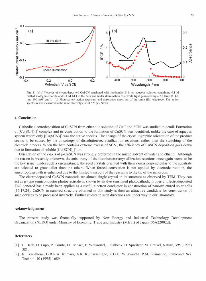
Since CuSCN is known to perform as a hole conductor in solid-state DSSCs, it is interesting to study dye-sensitization of electrodeposited CuSCN. Rhodamine B (RB) was employed as the sensitizer as it is known to adsorb on the surface of CuSCN [13]. Because iodide electrolyte typically used in DSSCs immediately convert CuSCN into CuI, aqueous electrolyte containing methylviologen as an electron acceptor was employed in the photoelectrochemical measurements. Fig. 11 shows I-V curves, photocurrent action spectrum and the absorption spectrum of RB-sensitized electrodeposited CuSCN. It exhibits rectification as expected for a p-type semiconductor electrode and generated a photocurrent of about 0.15 mA cm-1 under white light illumination (100 mW cm-2). Because of the limited surface area of the electrodeposited CuSCN, light absorption is limited due to the small amount of dye. However, the photocurrent action spectrum clearly indicates the contribution of RB for the photocurrent generation. RB molecules bound to the surface of CuSCN is able to inject hole from its photoexcited state to achieve cathodic dye-sensitization. Its incident photon to current conversion efficiency (IPCE) reached 4.4% at the absorption maximum of the dye. The efficiency is obviously limited by that of hole injection but could also be limited by that of electron transfer to methylviologen. This system is not readily useful for construction of solar cells, because of the limited efficiency and also by the use of toxic methylviologen. However, the CuSCN nanorod structure obtained in the present study may turn out to be useful for construction of nanostructured solar cells, when suitable sensitizer, either dye or inorganic quantum dots, and electron conductor that can fill up the gap of the nanorods are found.
Lina Sun et al. / Physics Procedia 14 (2011) 12–24 23
Fig. 11 (a) I-V curves of electrodeposited CuSCN sensitized with rhodamine B in an aqueous solution containing 0.1 M methyl viologen chloride and 0.1 M KCl in the dark and under illumination of a white light generated by a Xe lamp (> 420 nm, 100 mW cm-2). (b) Photocurrent action spectrum and absorption spectrum of the same film electrode. The action spectrum was measured in the same electrolyte at -0.3 V (vs. SCE).
4. Conclusion
Cathodic electrodeposition of CuSCN from ethanolic solution of Cu2+ and SCN- was studied in detail. Formation of [Cu(SCN)2]0 complex and its contribution to the formation of CuSCN was identified, unlike the case of aqueous system where only [Cu(SCN)]+ was the active species. The change of the crystallographic orientation of the product seems to be caused by the anisotropy of dissolution/recrystallization reactions, rather than the switching of the electrode process. When the bath contains extreme excess of SCN-, the efficiency of CuSCN deposition goes down due to formation of soluble [Cu(SCN)2]- ion.
Orientation of the c-axis of -CuSCN was strongly preferred in the mixed solvent of water and ethanol. Although the reason is presently unknown, the anisotropy of the dissolution/recrystallization reactions once again seems to be the key issue. Under such a circumstance, the seed crystals oriented with their c-axis perpendicular to the substrate are selected to grow taller than the others. When forced convection is not applied by electrode rotation, the anisotropic growth is enhanced due to the limited transport of the reactants to the tip of the nanorods.
The electrodeposited CuSCN nanorods are almost single crystal in its structure as observed by TEM. They can act as p-type semiconductor photoelectrode as shown by its dye-sensitized photocathodic property. Electrodeposited ZnO nanorod has already been applied as a useful electron conductor in construction of nanostructured solar cells [16,17,24]. CuSCN in nanorod structure obtained in this study is then an attractive candidate for construction of such devices to be processed inversely. Further studies in such directions are under way in our laboratory.
Acknowledgement
The present study was financially supported by New Energy and Industrial Technology Development Organization (NEDO) under Ministry of Economy, Trade and Industry (METI) of Japan (06A22002d).
References
[1] U. Bach, D. Lupo, P. Comte, J.E. Moser, F. Weissortel, J. Salbeck, H. Spreitzer, M. Grätzel, Nature, 395 (1998) 583.
[2] K. Tennakone, G.R.R.A. Kumara, A.R. Kumarasinghe, K.G.U. Wijayantha, P.M. Sirimanne, Semicond. Sci. Technol. 10 (1995) 1689.

24 Lina Sun et al. / Physics Procedia 14 (2011) 12–24
[3] G.R.R.A. Kumara, A. Konno, G.K.R. Senadeera, P.V.V. Jayaweera, D. De Silva, K. Tennakone, Sol. Energy Mater. Sol. Cells, 69 (2001) 195.
[4] B. O’Regan, M. Grätzel, Nature, 353 (1991) 737. [5] T. Yoshida, J.B. Zhang, D. Komatsu, S. Sawatani, H. Minoura, T. Pauporté, D. Lincot, T. Oekermann, D.
Schlettwain, H. Tada, D. Wöhrle, K. Funabiki, M. Matsui, H. Miura and H. Yanagi, Adv. Func. Mater. 19 (2009) 17.
[6] B. O’Regan, D.T. Schwartz, Adv. Mater. 12 (2000) 1263. [7] I. Kaiser, K. Ernst, C.-H. Fischer, R. Konenkamp, C. Rost, I. Sieber, M.C. Lux-Steiner, Sol. Energy Mater. Sol.
Cells, 67 (2001) 89. [8] C. Lévy-Clément, R. Tena-Zaera, M.A. Ryan, A. Katty, G. Hodes, Adv. Mater. 17 (2005) 1512. [9] K. Okabe, Y. Selk, T. Oekermann and T. Yoshida, Trans. Mater. Res. Soc. Jpn. 33 (2008) 1325. [10] W. Wu, Z. Jin, Z. Hua, Y. Fu, J. Qiu, Electrochim. Acta, 50 (2005) 2343. [11] K. Tennakone, A.R. Kumarasinghe, P.M. Sirimanne, G.R.R.A. Kumara, Thin Solid Films, 261 (1995) 307. [12] B. O’Regan, and D.T. Schwartz, Chem. Mater. 7 (1995) 1349. [13] Y. Selk, T. Yoshida and T. Oekermann, Thin Solid Films, 516 (2008) 7120. [14] J. He, H. Lindström, A. Hagfeldt, S.-E. Lindquist, Sol. Energy Mater. Sol. Cells, 62 (2000) 265. [15] S. Mori, S. Fukuda, S. Sumikura, Y. Takeda, Y. Tamaki, E. Suzuki, T. Abe, J. Phys. Chem. C, 112 (2008)
16134. [16] R. Tena-Zaera, A. Katty, S. Bastide, C. Lévy-Clément, B. O’Regan, V. Muñoz-Sanjosé, Thin Solid Films, 486
(2005) 372. [17] K. Takanezawa, K. Hirota, Q.-S. Wei, K. Tajima, and K. Hashimoto, J. Phys. Chem. C, 111 (2007) 7218. [18] I. Ivor, Chemist-Analyst. 54 (1965) 71-2 [19] T. Shirakashi, K. Tsuruta, K. Kakii, M. Kuriyama, Nippon Kagaku Kaishi, 8 (1984) 1330. [20] F.A.M.M. Gonlves, A.R. Trindade, C.S.M.F. Costa, J.C.S. Bernardo, I. Johnson, I.M.A. Fonseca, A.G.M.
Ferreira, J. Chem. Thermodynamics, 42 (2010) 1039. [21] V.P.S. Perrera, M.K.I. Senevirathna, P.K.D.D.P. Pitigala, K. Tennakone, Sol. Energy Mater. Sol. Cells, 86
(2005) 443. [22] J.E. Jaffe, T.C. Kaspar, T.C. Droubay, T. Varga, M.E. Bowden, G.J. Exarhos, J. Phys. Chem. C, 114 (2010)
9111. [23] J. Elias, R. Tena-Zaera, C. Lévy-Clément, J. Electroanal. Chem. 621 (2008) 171. [24] S. Haller, T. Sugiura, D. Lincot, T. Yoshida, Phys. Stat. Sol. (a), 207 (2010) 2252.


![Electrodeposition of Zn-Mn alloys from recycling battery leach … · 2014. 5. 20. · recovery by electrodeposition [1–4] is currently being studied in our laboratory [5]. Electrodeposition](https://img.pdfslide.us/doc/110x75/6112e3e4b1654c15ca54266d/electrodeposition-of-zn-mn-alloys-from-recycling-battery-leach-2014-5-20-recovery.jpg)