Embed Size (px)
Citation preview

© 2014 Caterpillar. All Rights Reserved. CAT, CATERPILLAR, BUILT FOR IT, their respective logos, “Caterpillar Yellow,” the “Power Edge” trade dress as well as corporate and product identity used herein, are trademarks of Caterpillar and may not be used without permission.
800.437.4228www.hawthornecat.com
Caterpillar® Performance
Handbook Edition 44
WHEEL DOZERS
SOIL COMPACTOR

22
Edition 44 22-1
CONTENTSWHEEL DOZERSFeatures . . . . . . . . . . . . . . . . . . . . . . . . . . . . . . . . . 22-1Specifications . . . . . . . . . . . . . . . . . . . . . . . . . . . . . 22-2Travel Speeds . . . . . . . . . . . . . . . . . . . . . . . . . . . . . 22-4Rimpull . . . . . . . . . . . . . . . . . . . . . . . . . . . . . . . . . 22-4Machine Selection . . . . . . . . . . . . . . . . . . . . . . . . . 22-6Counterweights and Ballast . . . . . . . . . . . . . . . . . 22-6Tire Selection & Maintenance. . . . . . . . . . . . . . . . 22-7Bulldozer Specifications . . . . . . . . . . . . . . . . . . . . 22-8Work Tools Specifications . . . . . . . . . . . . . . . . . . . 22-9
SOIL COMPACTORSFeatures . . . . . . . . . . . . . . . . . . . . . . . . . . . . . . . . .22-11Specifications . . . . . . . . . . . . . . . . . . . . . . . . . . . . 22-12Rimpull . . . . . . . . . . . . . . . . . . . . . . . . . . . . . . . . 22-13Compaction Fundamentals. . . . . . . . . . . . . . . . . 22-14Compactor Types and Zones of Application . . . 22-15Estimating Production (Example Problem). . . . . 22-16Production Table . . . . . . . . . . . . . . . . . . . . . . . . . 22-17Bulldozer Specifications . . . . . . . . . . . . . . . . . . . 22-17Ground Contact Pressures . . . . . . . . . . . . . . . . . 22-18
WHEEL DOZERSFeatures:
● Reliable Cat® power train: four-stroke-cycle diesel with adjustment-free fuel system … full power shift with single lever on-the-go shifting.
● Articulated frame steering with hinge point midway between front and rear axles … short turning radius, long wheelbase … rear and front wheels track at all times.
● Machine balance … equal weight distribution on axles when blading.
● All dozer functions, including tip and tilt, hydraulically controlled from operator’s seat.
● STIC™ (Steering Transmission Integrated Control) Steer ing is now offered on all Wheel Dozers, except the 814.
WHEEL DOZERSSOIL COMPACTORS
PHB-Sec22-1-WheelDozers-13(pg001-010).indd 1PHB-Sec22-1-WheelDozers-13(pg001-010).indd 1 12/20/13 9:03 AM12/20/13 9:03 AM

MODEL 814F2 824HFlywheel Power 173 kW 232 hp 264 kW 354 hp
Operating Weight* 21 713 kg 47,877 lb 28 724 kg 63,325 lb
Engine Model C9 ACERT™ C15 ACERT
Rated Engine RPM 2100 1800
No. Cylinders 6 6
Displacement 8.8 L 537 in3 15.2 L 928 in3
Speeds:
Forward 4 4
Reverse 4 4
Top Speed Forward 30.9 km/h 19.2 mph 32.1 km/h 20 mph
Turning Circle with Blade 7.17 m 23'6" 14.6 m 48'0"
Standard Tire Size 23.5-25, 12 PR (L-2) 29.5R25 (L-3)
Fuel Tank Refill Capacity 446 L 118 U.S. gal 672 L 178 U.S. gal
GENERAL DIMENSIONS:
Height (to top of ROPS) 3.3 m 10'8" 3.7 m 12'1"
Height (stripped top)** 2.4 m 7'9" 2.6 m 8'5"
Wheel Base 3.35 m 11'0" 3.7 m 12'1"
Overall Length with Dozer 6.9 m 22'8" 8.2 m 27'0"
Width (over standard tires) 2.8 m 9'2" 3.28 m 10'9"
Ground Clearance 366 mm 14.4" 400 mm 15.7"
Straight Bulldozer Straight Bulldozer
Width 3.6 m 11'8" 4.51 m 14'8"
Height 1.1 m 3'6" 1.23 m 4'0"
Capacity 2.73 LCM 3.6 LCY 4.67 LCM 6.11 LCY
Ground Clearance Below Skid Shoe 718 mm 2'4" 955 mm 3'1.6"
Depth of Cut 528 mm 20.8" 430 mm 16.9"
Tilt Adjustment 795 mm 2'6" 1.18 m 3'9"
Tip Adjustment 15° 22.4°
Lift Speed 0.4 m/sec 1.3 ft/sec 0.46 m/sec 1.46 ft/sec
*** Operating Weight includes straight dozer, lubricants, coolant, ROPS cab, full fuel tank and operator. 75% CaCl2 in all tires adds the following weight to each model: 814F2 — 2342 kg (5164 lb), 824H — 4296 kg (9472 lb).
***Height (stripped top) — without ROPS, exhaust, seat back or easily removed encumbrances.
22-2 Edition 44
Wheel Dozers Specifications
PHB-Sec22-1-WheelDozers-13(pg001-010).indd 2PHB-Sec22-1-WheelDozers-13(pg001-010).indd 2 12/20/13 9:03 AM12/20/13 9:03 AM

22
Edition 44 22-3
Wheel DozersSpecifications
MODEL 834K 844H 854KU.S. EPA Tier 4 Final
Flywheel Power: Prefix TWY Prefix H8M
Net 370 kW 496 hp — 607 kW 814 hp
Max. 419 kW 562 hp — 671 kW 900 hp
U.S. EPA Tier 3 Flywheel Power: Prefix LWY
Net 370 kW 496 hp 468 kW 627 hp —
Max. 419 kW 562 hp — —
U.S. EPA Tier 2 (Equivalent) Final Flywheel Power: Prefix LWY Prefix H9K
Net 370 kW 496 hp — 607 kW 814 hp
Max. 419 kW 562 hp — 676 kW 907 hp
Operating Weight* 47 750 kg 105,271 lb 70 815 kg 156,120 lb 98 100 kg 216,273 lb
Emission Level Tier 4/Tier 3 Equivalent/Tier 2 Equivalent
— Tier 4/Tier 2 Equivalent
Engine Model C18 ACERT C27 ACERT C32 ACERT
Rated Engine RPM 1800 2000 1750
No. Cylinders 6 12 12
Displacement 18.1 L 1105 in3 27.1 L 1666 in3 32.1 L 1959 in3
Speeds:
Forward 4 3 3
Reverse 3 3 3
Top Speed Forward 35.4 km/h 22 mph 21 km/h 13 mph 21.2 km/h 13.2 mph
Turning Circle with Blade 17.6 m 57'9" 21.73 m 71'4" 23.4 m 76'9"
Standard Tire Size 35/65-R33, 24 PR (L-4) 45/65-R39, PR (L-4) 45/65-R45 (L-4)
Fuel Tank Refill Capacity 793 L 209 U.S. gal 1016 L 268 U.S. gal 1562 L 413 U.S. gal
Diesel Exhaust Fluid Tank Refill Capacity (required for Tier 4 Final machines) 32 L 8.5 U.S. gal — 32 L 8.5 U.S. gal
GENERAL DIMENSIONS:
Height (to top of ROPS) 4.18 m 13'7" 5.023 m 16'6" 5590 mm 18'3"
Height (stripped top)** 3.15 m 10'4" 3.8 m 12'6" 5234 mm 17'2"
Wheel Base 4.55 m 14'11" 4.6 m 15'1" 5890 mm 19'3"
Overall Length with Dozer 10.42 m 34'2" 10.94 m 35'9" 13 405 mm 44'0"
Width (over standard tires) 3.47 m 11'5" 4.37 m 14'4" 3556 mm 11'8"
Ground Clearance 531 mm 21" 431 mm 1'5" 691 mm 27"
Straight Bulldozer Semi-U Dozer Semi-U Dozer
Width 5.07 m 16'8" 5.278 m 17'4" 6321 mm 20'8"
Height 1.54 m 5'0" 1.877 m 6'2" 5590 mm 18'3"
Capacity 7.87 LCM*** 10.3 LCY*** 16.1 m3 21.1 yd3 25.4 m3 33.1 yd3
Ground Clearance Below Skid Shoe 1324 mm 4'4" 1372 mm 4'6" 691 mm 27"
Depth of Cut 557 mm 21.9" 466 mm 18" 398 mm 1'3"
Tilt Adjustment 1.27 m 4'2" 830 mm 2'9" 1165 mm 3'8"
Tip Adjustment 21° 13° 15°
Lift Speed 0.81 m/sec 2.66 ft/sec 0.353 m/sec 1.2 ft/sec 0.310 m/sec 1.05 ft/sec*** Operating Weight of 844H and 854K includes Semi-U, coolant, ROPS cab, full fuel tank and operator.*** Operating Weight of 834K includes straight dozer, (U-blade) lubricants, coolant, ROPS cab, full fuel tank and operator.***Height (stripped top) — without ROPS, exhaust, seat back or easily removed encumbrances.***Capacity of 834K U-Blade is 11.16 LCM (14.6 LCY).
PHB-Sec22-1-WheelDozers-13(pg001-010).indd 3PHB-Sec22-1-WheelDozers-13(pg001-010).indd 3 12/20/13 9:03 AM12/20/13 9:03 AM

22-4 Edition 44
MODEL 814F2 824H 834K* 844H* 854K*FORWARD GEAR km/h mph km/h mph km/h mph km/h mph km/h mph
1 5.7 3.6 6.1 3.8 6.8 4.2 7.0 4.4 6.8 4.2
2 10.2 6.4 10.5 6.5 11.6 7.2 12.2 7.6 12.1 7.5
3 17.9 11.2 18.3 11.4 20.3 12.6 21.0 13.0 20.9 13.0
4 31.0 19.3 32.1 20.0 35.4 22.0 — —
REVERSE GEAR
1 6.5 4.1 6.9 4.3 6.8 4.2 7.7 4.6 7.5 4.7
2 11.6 7.3 12.0 7.5 12.2 7.6 13.4 8.4 13.3 8.3
3 20.4 12.7 20.8 13.0 21.4 13.3 23.0 14.3 23.0 14.3
4 34.9 21.8 36.6 22.7 — — —
*2% rolling resistance.
Wheel Dozers Travel SpeedsRimpull
KEY1 – 1st Gear2 – 2nd Gear3 – 3rd Gear4 – 4th Gear
510
60555045403530252015
2
0 2 4 6 8 10 12 14 16 18 20 22 240
10
20
30
40
50
60
70
80
0
4
8
12
16
20
24
28
32
36
1
0 4 8 12 16 20 24 28 32 36
2
34
824H
mph
SPEED
RIM
PU
LL
TOTA
L R
ES
ISTA
NC
E (
%)
(Gra
de
+ R
olli
ng
)
km/h
lb x1000
kg x1000
510
60555045403530252015
20 2 4 6 8 10 12 14 16 18 20 22 24
0
4
8
12
16
20
24
28
32
36
40
44
48
52
56
60
64
0
4
8
12
16
20
24
28
2
6
10
14
18
22
26
1
0 4 8 12 16 20 24 28 32 36
2
34
814F2
mph
SPEED
RIM
PU
LL
TOTA
L R
ES
ISTA
NC
E (
%)
(Gra
de
+ R
olli
ng
)
km/h
lb x1000
kg x1000
PHB-Sec22-1-WheelDozers-13(pg001-010).indd 4PHB-Sec22-1-WheelDozers-13(pg001-010).indd 4 12/20/13 9:03 AM12/20/13 9:03 AM

22
Edition 44 22-5
Wheel DozersRimpull
KEY1 – 1st Gear2 – 2nd Gear3 – 3rd Gear4 – 4th Gear
Direct Drive
Torque Converter0
5
10
15
20
25
30
35
40
45
50
55
60
65
70
75
80
85
90
0 2 4 6 8 10 12 14 16 18 20 22 24
1
3L
2L
3
4L
2
4
45
40
2
35
30
25
5
20
15
10
50
60
55
0
4
8
12
16
20
24
28
32
36
40
0 4 8 12 16 20 24 28 32 36 40
834K
mph
SPEED
RIM
PU
LL
km/h
lb x1000
kg x1000
TOTA
L R
ES
ISTA
NC
E (
%)
(Gra
de
+ R
olli
ng
)
0
10
20
30
40
50
60
70
80
90
100
110
120
130
0 1 2 3 4 5 6 7 8 9 10 11 12 13 14 15
45
40
2
35
30
25
5
20
15
10
1
3L
2L
3
1L
2
60
55
50
0
5
10
15
20
25
30
35
40
45
50
55
60
0 2 4 6 8 10 12 14 16 18 20 22 24
844H
mph
SPEED
RIM
PU
LL
km/h
lb x1000
kg x1000
TOTA
L R
ES
ISTA
NC
E (
%)
(Gra
de
+ R
olli
ng
)
0
10
20
30
40
50
60
70
80
90
100
110
120
130
140
150
160
170
180
0 2 4 6 8 10 12 14 16
0
5
10
15
20
25
30
35
40
45
50
55
60
65
70
75
80
0 2 4 6 8 10 12 14 16 18 20 22 24
45
40
2
35
30
25
5
20
15
10
50
60
55
1
3L
2L
3
2
854K
mph
SPEED
RIM
PU
LL
km/h
lb x1000
kg x1000
TOTA
L R
ES
ISTA
NC
E (
%)
(Gra
de
+ R
olli
ng
)
PHB-Sec22-1-WheelDozers-13(pg001-010).indd 5PHB-Sec22-1-WheelDozers-13(pg001-010).indd 5 12/20/13 9:03 AM12/20/13 9:03 AM

CONSIDERATIONS IN MACHINE SELECTIONThe following factors should be considered when
comparing wheels vs. tracks:
Traction You can figure coefficient of traction, depending on underfoot conditions, from the Table Section in this book. Wheels — up to 0.65 (in quarry pit with good floor) Track — up to 0.90 (in soils permitting grouser penetration)Usable Rimpull = Machine Weight × Coefficient of Traction
Speed Wheels — travel speeds up to three times higher than track.
Maneuverability Articulated steering and good visibility give wheel tractors high maneuverability.
Cost See Owning and Operating Costs section. Tire vs. undercarriage costs can often be the deciding factor in selecting wheels or tracks.
CompactionGround Pressure: Wheels — from 241 kPa (35 psi) to 310 kPa (45 psi) Tracks — from 82 kPa (12 psi) to 97 kPa (14 psi)
Application Utility … mobility, maneuverability and good speed suit wheel tractors for yard and stockpile work and for clean-up around shovels. Lower maintenance costs may be realized in certain soils that can be highly abrasive to track-type undercarriages. Coal pile … recommend wheel tractors in this appli-ca tion when following conditions are present:— Long push distances— Need for good material spread— High degree of compaction desired Production Dozing … a wheel tractor should be con-sidered in the following conditions:— Long push distances— Loose soils, little or no rock— Level or downhill work— Good underfoot conditions
Pushloading Scrapers … a wheel tractor should be con sidered in the following conditions:— Thin scraper cut— Good underfoot conditions — no rock— Higher push speeds Chip and Coal Scoops … a wheel dozer scoop should be considered in the following conditions:— Long push distances— Light, well processed materials such as coal or
wood chips— High degree of compaction desired— Low to modest grades
COUNTERWEIGHTS AND BALLASTFor each specific application, there is a correct machine
weight for proper balancing of traction, flotation, mobil-ity and response.● Low machine weight may increase tire slipping and
wear, but improves flotation, mobility and machine response.
● High machine weight increases traction, but decreases mobility and response.
The machine weight is optimum for the operating con-ditions when wheel slipping barely occurs in the gear being used. Weight distribution under operating condi-tions should then be approximately equal between the wheels to balance power to each axle.
ApplicationLower machine weight is usually required for applica-
tions such as fill spreading, stockpiling, road mainte-nance, towing compactors, and shovel cleanup. These are generally performed in either first or second gear. However, usage of second gear may involve a tradeoff of increased GET wear on the blade.
Higher machine weight is usually required for appli-cations such as heavy dozing and push-loading, which are generally performed in first gear.
22-6 Edition 44
Wheel Dozers Machine SelectionCounterweights and Ballast
PHB-Sec22-1-WheelDozers-13(pg001-010).indd 6PHB-Sec22-1-WheelDozers-13(pg001-010).indd 6 12/20/13 9:03 AM12/20/13 9:03 AM

22
TIRE SELECTION & MAINTENANCERequirements of traction, flotation and tire life are
met by a choice of tire size, tread design and inflation pressure.
Tire WidthFor good conditions with little rolling resistance on
surfaces where flotation is no problem, a narrower tire may be most economical. It may also be considered in muddy conditions in which the mud can be penetrated to reach firm earth underneath.
Where flotation problems and increased rolling resis-tance are encountered, wider tires are recom mended. The greater contact area and shallower penetration increases flotation.
Tire SizeLarger optional tires will also improve flotation in soft
conditions. With larger diameter, rimpull will be reduced which may be desirable to help control wheel spin.
Rock — Deep Tread (L-4) provides 50% more tread depth, thicker undertread and sidewall with increased tire life when compared to the L-3 tire. Recommended in rock conditions where sharp fragments cause high tire wear or sudden failures.
Rock — Extra Deep Tread (L-5) provides 150% more tread depth when compared to the L-3 tire. Intended for severe rock conditions with extreme penetration hazards.
Inflation PressureIn average operating conditions the recommended
inflation pressure prevents excessive deflection and mini-mizes tire rollover on side slopes.
Over-inflationReduces amount of tread contact with ground and
provides less flotation. Over-inflation causes center of tread to wear faster and increases the chance of cuts and impact breaks.
Under-inflationCan cause permanent tire damage in the form of flex
breaks, radial cracks, and tread or ply separation. On jobs where wrinkling and bead rollover are not apparent, inflation pressure may be reduced to a minimum of:
Bias Ply — 170 kPa (25 psi) on 35/65-33170 kPa (25 psi) on 29.5-25170 kPa (25 psi) on 26.5-25170 kPa (25 psi) on 23.5-25
Radial — 310 kPa (45 psi) on 35/65-R33310 kPa (45 psi) on 29.5-R25205 kPa (30 psi) on 26.5-R25240 kPa (35 psi) on 23.5-R25
Reduced pressure will:Increase flotation and traction in sand.Improve envelopment characteristics to reduce sud-
den death failure on rock jobs.Provide better tread wear by reducing contact pres-
sure between tire and ground.
Consult your tire manufacturer before changing tire pressures.
Edition 44 22-7
Wheel DozersTire Selection & Maintenance
PHB-Sec22-1-WheelDozers-13(pg001-010).indd 7PHB-Sec22-1-WheelDozers-13(pg001-010).indd 7 12/20/13 9:03 AM12/20/13 9:03 AM
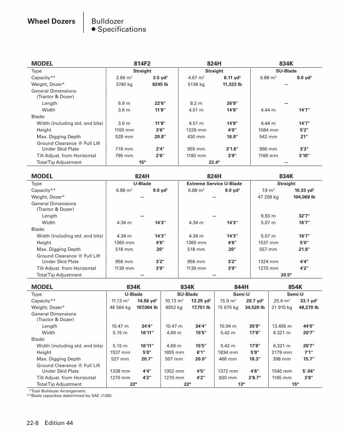
MODEL 814F2 824H 834KType Straight Straight SU-BladeCapacity** 2.66 m3 3.5 yd3 4.67 m3 6.11 yd3 6.88 m3 9.0 yd3
Weight, Dozer* 3740 kg 8245 lb 5136 kg 11,323 lb —General Dimensions
(Tractor & Dozer)Length 6.9 m 22'6" 8.2 m 26'9" —Width 3.6 m 11'8" 4.51 m 14'8" 4.44 m 14'7"
Blade:Width (including std. end bits) 3.6 m 11'8" 4.51 m 14'8" 4.44 m 14'7"Height 1100 mm 3'6" 1229 mm 4'0" 1584 mm 5'2"Max. Digging Depth 528 mm 20.8" 430 mm 16.9" 542 mm 21"Ground Clearance @ Full Lift
Under Skid Plate 718 mm 2'4" 955 mm 3'1.6" 996 mm 3'3"Tilt Adjust. from Horizontal 795 mm 2'6" 1180 mm 3'9" 1166 mm 3'10"Total Tip Adjustment 15° 22.4° —
MODEL 824H 824H 834KType U-Blade Extreme Service U-Blade StraightCapacity** 6.88 m3 9.0 yd3 6.88 m3 9.0 yd3 7.9 m3 10.33 yd3
Weight, Dozer* — — 47 206 kg 104,069 lbGeneral Dimensions
(Tractor & Dozer)Length — — 9.93 m 32'7"Width 4.34 m 14'3" 4.34 m 14'3" 5.07 m 16'7"
Blade:Width (including std. end bits) 4.34 m 14'3" 4.34 m 14'3" 5.07 m 16'7"Height 1365 mm 4'6" 1365 mm 4'6" 1537 mm 5'0"Max. Digging Depth 518 mm 20" 518 mm 20" 557 mm 21.9"Ground Clearance @ Full Lift
Under Skid Plate 956 mm 3'2" 956 mm 3'2" 1324 mm 4'4"Tilt Adjust. from Horizontal 1139 mm 3'9" 1139 mm 3'9" 1270 mm 4'2"Total Tip Adjustment — — 20.5°
MODEL 834K 834K 844H 854KType U-Blade SU-Blade Semi-U Semi-UCapacity** 11.13 m3 14.56 yd3 10.13 m3 13.25 yd3 15.9 m3 20.7 yd3 25.4 m3 33.1 yd3
Weight, Dozer* 48 564 kg 107,064 lb 8052 kg 17,751 lb 15 670 kg 34,520 lb 21 910 kg 48,270 lbGeneral Dimensions
(Tractor & Dozer)Length 10.47 m 34'4" 10.47 m 34'4" 10.94 m 35'9" 13.405 m 44'0"Width 5.15 m 16'11" 4.69 m 15'5" 5.42 m 17'8" 6.321 m 20'7"
Blade:Width (including std. end bits) 5.15 m 16'11" 4.69 m 15'5" 5.42 m 17'8" 6.321 m 20'7"Height 1537 mm 5'0" 1855 mm 6'1" 1834 mm 5'9" 2179 mm 7'1"Max. Digging Depth 527 mm 20.7" 507 mm 20.0" 466 mm 18.3" 398 mm 15.7"Ground Clearance @ Full Lift
Under Skid Plate 1338 mm 4'4" 1352 mm 4'5" 1372 mm 4'6" 1540 mm 5'.04"Tilt Adjust. from Horizontal 1270 mm 4'2" 1270 mm 4'2" 830 mm 2'8.7" 1165 mm 3'8"Total Tip Adjustment 22° 22° 13° 15°
**Total Bulldozer Arrangement.**Blade capacities determined by SAE J1265.
22-8 Edition 44
Wheel Dozers Bulldozer● Specifications
PHB-Sec22-1-WheelDozers-13(pg001-010).indd 8PHB-Sec22-1-WheelDozers-13(pg001-010).indd 8 12/20/13 9:03 AM12/20/13 9:03 AM

22
Edition 44 22-9
COAL U-BLADE 814F2 824H 834KModel: Coal U-Blade Coal U-Blade Coal U-Blade
Replaces “S” BladeBlade:
Capacity 11 m3 14 yd3 16.1 m3 21 yd3 22.3 m3 29 yd3
Length (Cutting Width) 4318 mm 14'2" 4801 mm 15'9" 5680 mm 18'7"Height, wing section
(tapered down) 1473 mm 4'10" 1803 mm 5'11" 1960 mm 6'5"Wing Angle 25° 30° 30°Weight, Installed
(Without Hydraulics) 1950 kg 4300 lb 3193 kg 7040 lb 5020 kg 11,300 lb
844H 854KModel: Coal U-Blade Coal U-Blade
Replaces “S” BladeBlade:
Capacity 30.7 m3 40.2 yd3 44.7 m3 58.2 yd3
Length (Cutting Width) 5846 mm 19'2" 7200 mm 23'7"Height, wing section
(tapered down) 2024 mm 6'8" 2500 mm 8'2"Wing Angle 30° 30°Weight, Installed
(Without Hydraulics) 6237 kg 13,830 lb 10 333 kg 22,780 lb
WOODCHIP U-BLADE 824H 834KModel: Woodchip U-Blade Woodchip U-Blade
Replaces “S” BladeBlade:
Capacity 24 m3 31 yd3 30.1 m3 40 yd3
Length (Cutting Width) 4775 mm 15'8" 5700 mm 18'8"Height, wing section 2261 mm 7'5" 2350 mm 7'8"Wing Angle 30° 30°Weight 3515 kg 7750 lb 5155 kg 11,600 lb
COAL SCOOP WITH TILT 814F2 824H 834KModel: Coal Scoop with Tilt Coal Scoop with Tilt Coal Scoop with TiltScoop:
Lift and Carrying Capacity 11.5 m3 15 yd3 13.4 m3 17.5 yd3 22.9 m3 30 yd3
Dozing Capacity 19.1 m3 25 yd3 26.8 m3 35 yd3 44.2 m3 58 yd3
Width 3734 mm 12'3" 4058 mm 13'4" 4851 mm 15'11"Height 1626 mm 5'4" 1839 mm 6'1" 2339 mm 7'8"Weight 5216 kg 11,500 lb 6763 kg 14,913 lb 9711 kg 21,409 lb
CHIP SCOOP WITH TILT 814F2 824H 834KModel: Chip Scoop with Tilt Chip Scoop with Tilt Chip Scoop with TiltScoop:
Lift and Carrying Capacity 15.3 m3 20 yd3 20.6 m3 27 yd3 26.7 m3 35 yd3
Dozing Capacity 30.6 m3 40 yd3 41.3 m3 54 yd3 53.5 m3 70 yd3
Width 3734 mm 12'3" 4039 mm 13'3" 4851 mm 15'11"Height 2286 mm 7'6" 2489 mm 8'2" 2649 mm 8'8"Weight 5390 kg 11,880 lb 11 420 kg 19,125 lb 9804 kg 21,614 lb
Wheel DozersWork Tools● Specifications
PHB-Sec22-1-WheelDozers-13(pg001-010).indd 9PHB-Sec22-1-WheelDozers-13(pg001-010).indd 9 12/20/13 9:03 AM12/20/13 9:03 AM

22-10 Edition 44
Notes —
PHB-Sec22-1-WheelDozers-13(pg001-010).indd 10PHB-Sec22-1-WheelDozers-13(pg001-010).indd 10 12/20/13 9:03 AM12/20/13 9:03 AM
22
Edition 44 22-11
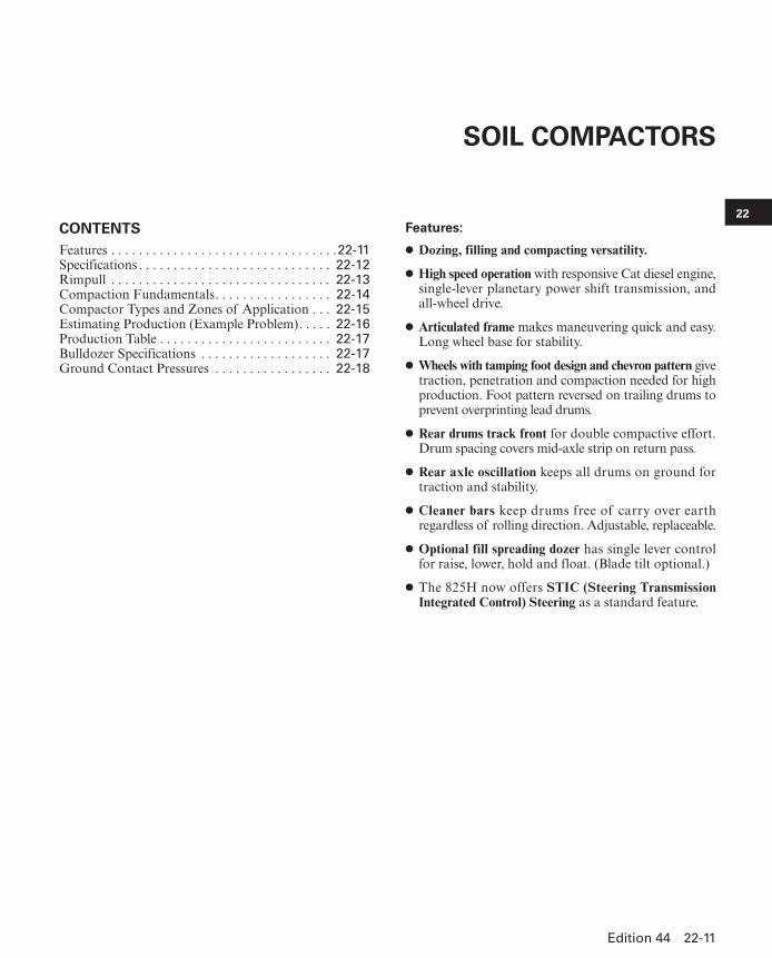
CONTENTSFeatures . . . . . . . . . . . . . . . . . . . . . . . . . . . . . . . . .22-11Specifications . . . . . . . . . . . . . . . . . . . . . . . . . . . . 22-12Rimpull . . . . . . . . . . . . . . . . . . . . . . . . . . . . . . . . 22-13Compaction Fundamentals. . . . . . . . . . . . . . . . . 22-14Compactor Types and Zones of Application . . . 22-15Estimating Production (Example Problem). . . . . 22-16Production Table . . . . . . . . . . . . . . . . . . . . . . . . . 22-17Bulldozer Specifications . . . . . . . . . . . . . . . . . . . 22-17Ground Contact Pressures . . . . . . . . . . . . . . . . . 22-18
Features:
● Dozing, filling and compacting versatility.
● High speed operation with responsive Cat diesel engine, single-lever planetary power shift transmis sion, and all-wheel drive.
● Articulated frame makes maneuvering quick and easy. Long wheel base for stability.
● Wheels with tamping foot design and chevron pattern give traction, penetration and compaction needed for high production. Foot pattern reversed on trailing drums to prevent overprinting lead drums.
● Rear drums track front for double compactive effort. Drum spacing covers mid-axle strip on return pass.
● Rear axle oscillation keeps all drums on ground for traction and stability.
● Cleaner bars keep drums free of carry over earth re gard less of rolling direction. Adjustable, replace able.
● Optional fill spreading dozer has single lever control for raise, lower, hold and float. (Blade tilt optional.)
● The 825H now offers STIC (Steering Transmission Integrated Control) Steering as a standard feature.
SOIL COMPACTORS
PHB-Sec22-2-SoilCompactors-13(pg011-018).indd 11PHB-Sec22-2-SoilCompactors-13(pg011-018).indd 11 12/20/13 9:03 AM12/20/13 9:03 AM

MODEL 815F2 825HFlywheel Power 173 kW 232 hp 264 kW 354 hp
Operating Weight* 20 755 kg 45,765 lb 32 734 kg 72,164 lb
Engine Model C9 ACERT C15 ACERT
Rated Engine RPM 2100 1800
No. Cylinders 6 6
Displacement 8.8 L 537 in3 15.1 L 928 in3
Speeds:
Forward 3 3
Reverse 3 3
Turning Radius — outside Corner of Blade 6.45 m 21'3" 7.4 m 24'0"
Fuel Tank Refill Capacity 446 L 118 U.S. gal 603 L 159 U.S. gal
TAMPING FOOT WHEELS:
Each Drum Width 991 mm 3'3" 1125 mm 3'8"
Diameters, over feet 1.42 m 4'8" 1.68 m 5'5"
Diameters, over drum 1.03 m 3'5" 1.29 m 4'3"
Feet per Wheel 60 65
Feet per Row 12 13
Rows of Feet 5 5
Foot Length 191 mm 7.5" 188 mm 7.4"
End Area Per Foot 134 cm2 20.8 in2 192 cm2 29.75 in2
Width of Two Pass Coverage 4.2 m 13'9" 5.3 m 17'4"
GENERAL DIMENSIONS:
Height (top of ROPS) 3.34 m 11'0" 3.75 m 12'3"
Height (stripped top)** 2.39 m 7'10" 2.69 m 8'10"
Wheel Base 3.35 m 11'0" 3.7 m 12'1"
Overall Length with Dozer 6.80 m 23'6" 8.43 m 27'8"
Width over Drums 3.24 m 10'8" 3.65 m 12'0"
Ground Clearance 390 mm 15.4" 414 mm 16"
STRAIGHT BULLDOZER:
Width over End Bits 3.76 m 12'4" 4.62 m 15'1"
Height with Cutting Edge 860 mm 2'10" 1030 mm 3'4"
**Operating Weight includes coolant, lubricants, bulldozer, hydraulics, ROPS canopy, full fuel tank and operator.**Height (stripped top) — without ROPS, exhaust, seat back or other easily removed encumbrances.
22-12 Edition 44
Soil Compactors Specifications
PHB-Sec22-2-SoilCompactors-13(pg011-018).indd 12PHB-Sec22-2-SoilCompactors-13(pg011-018).indd 12 12/20/13 9:03 AM12/20/13 9:03 AM

22
mph
Edition 44 22-13
Soil CompactorsRimpull
KEY1 – 1st Gear2 – 2nd Gear3 – 3rd Gear
510
60555045403530252015
2
0 2 4 6 8 10 12 140
60
66
72
78
84
90
54
6
12
18
24
30
36
42
48
0
2
4
6
8
10
12
14
16
18
20
22
24
26
28
30
32
34
36
38
40
0 2 4 6 8 10 12 14 16 18 20
1
2
3
825H
mph
SPEED
RIM
PU
LL
TOTA
L R
ES
ISTA
NC
E (
%)
(Gra
de
+ R
olli
ng
)
km/h
lb x1000
kg x1000
510
60555045403530252015
20 2 4 6 8 10 12 14 16 18 20 22 24
0
4
8
12
16
20
24
28
32
36
40
44
48
52
56
0
4
8
12
16
20
24
2
6
10
14
18
22
26
1
2
0 4 8 12 16 20 24 28 32 36
3
815F2
SPEED
RIM
PU
LL
TOTA
L R
ES
ISTA
NC
E (
%)
(Gra
de
+ R
olli
ng
)
km/h
lb x1000
kg x1000
PHB-Sec22-2-SoilCompactors-13(pg011-018).indd 13PHB-Sec22-2-SoilCompactors-13(pg011-018).indd 13 12/20/13 9:03 AM12/20/13 9:03 AM

22-14 Edition 44
Soil Compactors Compaction Fundamentals
COMPACTION FUNDAMENTALSThe following discussion applies to soil compaction
only.
DefinitionCompaction is the process of physically densifying
or packing the soil … resulting in increased weight per unit volume. It is generally accepted that the strength of a soil can be increased by densification. Three impor-tant factors affect compaction.
— Material gradation— Moisture content— Compactive effortMaterial Gradation — refers to the distribution (% by
weight) of the different particle sizes within a given soil sample. A sample is well-graded if it contains a good, even distribution of particle sizes. A sample composed of predominantly one size particle, is said to be poorly-graded. In terms of compaction, a well-graded soil will compact more easily than one that is poorly-graded. In well-graded material the smaller particles tend to fill the empty spaces between the larger particles, leaving fewer voids after compaction.
MATERIAL GRADATION
Moisture Content — or the amount of water present in a soil, is very important to compaction. Water lubricates soil particles thus helping them slide into the most dense position. Water also creates clay particle bonding, giving cohesive materials their sticky qualities.
OPTIMUM MOISTURE
Heavy clay 17.5%Silty clay 15.0%Sandy clay 13.0%Sand 10.0%Gravel, sand, clay mix
(pit run)7.0%
Experience has shown that it is very difficult, if not impossible, to achieve proper compaction in materials that are too dry or too wet. Soil experts have determined that in practically every soil there is an amount of water, called optimum moisture content, at which it is possible to obtain maximum density with a given amount of compactive effort. The curve below shows this relation-ship between dry density and moisture content. It is called a compaction curve, moisture-density curve or Proctor curve.
Compactive Effort — refers to the method employed by a compactor to impart energy into the soil to achieve compaction. Compactors are designed to use one or a combination of the following types of compactive effort.
— Static weight (or pressure)— Kneading action (or manipulation)— Impact (or sharp blow)— Vibration (or shaking)
Poorly-graded Well-graded
Moisture Content ▶
MaximumDensity
OptimumMoisture
Dry
Den
sity
▶
MOISTURE CONTENT
PHB-Sec22-2-SoilCompactors-13(pg011-018).indd 14PHB-Sec22-2-SoilCompactors-13(pg011-018).indd 14 12/20/13 9:03 AM12/20/13 9:03 AM
22
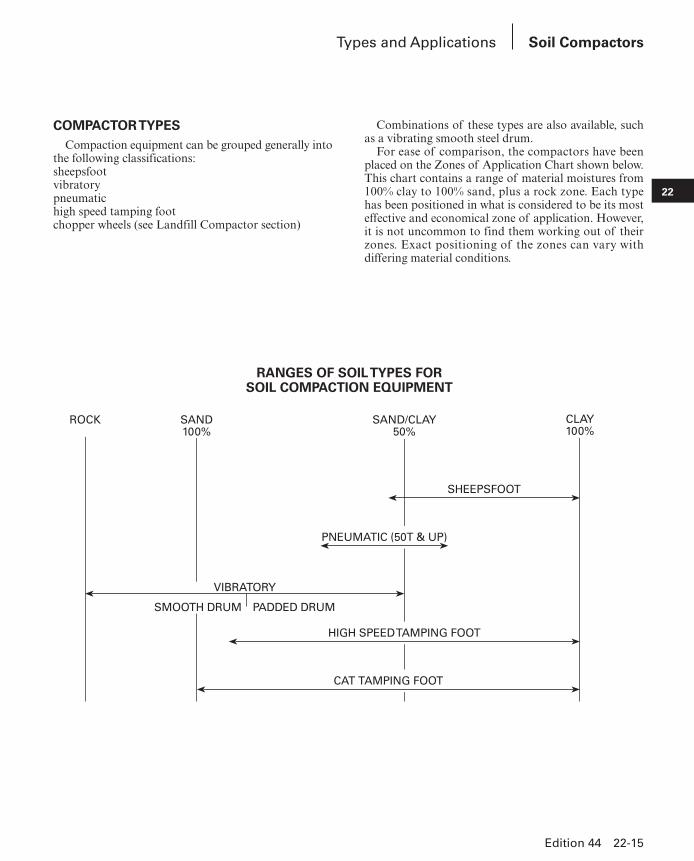
COMPACTOR TYPESCompaction equipment can be grouped generally into
the following classifications:sheepsfootvibratorypneumatichigh speed tamping footchopper wheels (see Landfill Compactor section)
Combinations of these types are also available, such as a vibrating smooth steel drum.
For ease of comparison, the compactors have been placed on the Zones of Application Chart shown below. This chart contains a range of material moistures from 100% clay to 100% sand, plus a rock zone. Each type has been positioned in what is considered to be its most effective and economical zone of application. However, it is not uncommon to find them working out of their zones. Exact positioning of the zones can vary with dif fering material conditions.
RANGES OF SOIL TYPES FORSOIL COMPACTION EQUIPMENT
Edition 44 22-15
Soil CompactorsTypes and Applications
CLAY100%
ROCK SAND100%
SAND/CLAY50%
SHEEPSFOOT
PNEUMATIC (50T & UP)
VIBRATORY
SMOOTH DRUM PADDED DRUM
HIGH SPEED TAMPING FOOT
CAT TAMPING FOOT
PHB-Sec22-2-SoilCompactors-13(pg011-018).indd 15PHB-Sec22-2-SoilCompactors-13(pg011-018).indd 15 12/20/13 9:03 AM12/20/13 9:03 AM
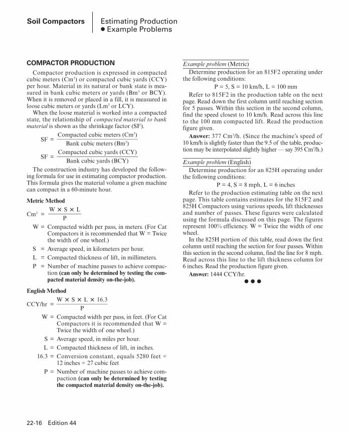
COMPACTOR PRODUCTIONCompactor production is expressed in compacted
cubic meters (Cm3) or compacted cubic yards (CCY) per hour. Material in its natural or bank state is mea-sured in bank cubic meters or yards (Bm3 or BCY). When it is removed or placed in a fill, it is measured in loose cubic meters or yards (Lm3 or LCY).
When the loose material is worked into a compacted state, the relationship of compacted material to bank material is shown as the shrinkage factor (SF).
Compacted cubic meters (Cm3)SF = ___________________________ Bank cubic meters (Bm3)
Compacted cubic yards (CCY)SF = ___________________________ Bank cubic yards (BCY)
The construction industry has developed the follow-ing formula for use in estimating compactor produc tion. This formula gives the material volume a given machine can compact in a 60-minute hour.
Metric Method W × S × LCm3 = ___________ P W = Compacted width per pass, in meters. (For Cat
Compactors it is recommended that W = Twice the width of one wheel.)
S = Average speed, in kilometers per hour. L = Compacted thickness of lift, in millimeters. P = Number of machine passes to achieve com pac-
tion (can only be determined by testing the com-pacted material density on-the-job).
English Method W × S × L × 16.3CCY/hr = _________________
P W = Compacted width per pass, in feet. (For Cat
Compactors it is recommended that W = Twice the width of one wheel.)
S = Average speed, in miles per hour. L = Compacted thickness of lift, in inches. 16.3 = Conversion constant, equals 5280 feet ÷
12 inches ÷ 27 cubic feet P = Number of machine passes to achieve com-
paction (can only be determined by testing the compacted material density on-the-job).
Example problem (Metric)Determine production for an 815F2 operating under
the following conditions:P = 5, S = 10 km/h, L = 100 mm
Refer to 815F2 in the production table on the next page. Read down the first column until reaching section for 5 passes. Within this section in the second column, find the speed closest to 10 km/h. Read across this line to the 100 mm compacted lift. Read the production figure given.
Answer: 377 Cm3/h. (Since the machine’s speed of 10 km/h is slightly faster than the 9.5 of the table, produc-tion may be interpolated slightly higher — say 395 Cm3/h.)
Example problem (English)Determine production for an 825H operating under
the following conditions:P = 4, S = 8 mph, L = 6 inches
Refer to the production estimating table on the next page. This table contains estimates for the 815F2 and 825H Compactors using various speeds, lift thicknesses and number of passes. These figures were calculated using the formula discussed on this page. The figures represent 100% efficiency. W = Twice the width of one wheel.
In the 825H portion of this table, read down the first column until reaching the section for four passes. Within this section in the second column, find the line for 8 mph. Read across this line to the lift thickness column for 6 inches. Read the production figure given.
Answer: 1444 CCY/hr.● ● ●
22-16 Edition 44
Soil Compactors Estimating Production● Example Problems
PHB-Sec22-2-SoilCompactors-13(pg011-018).indd 16PHB-Sec22-2-SoilCompactors-13(pg011-018).indd 16 12/20/13 9:03 AM12/20/13 9:03 AM

22
Edition 44 22-17
PRODUCTION TABLEMODEL AND
MACHINE PASSES*
AVERAGE SPEEDCOMPACTED LIFT THICKNESS
100 mm 4 in 150 mm 6 in 200 mm 8 in 250 mm 10 inkm/h mph m3/h yd3/hr m3/h yd3/hr m3/h yd3/hr m3/h yd3/hr
815F2 3 6.5 4 419 548 628 822 837 1095 — 9.5 6 628 822 942 1232 1256 1643 —13.0 8 837 1095 1256 1643 1675 2191 —
4 6.5 4 314 411 471 616 628 822 — 9.5 6 471 616 706 924 942 1232 —13.0 8 628 822 942 1232 1256 1643 —
5 6.5 4 251 329 377 493 502 657 — 9.5 6 377 493 565 739 754 986 —13.0 8 502 657 754 986 1005 1314 —
6 6.5 4 286 274 314 411 419 548 — 9.5 6 314 411 471 616 628 822 —13.0 8 419 548 628 822 837 1095 —
825H 3 6.5 4 488 642 731 962 975 1283 1219 1604 9.5 6 713 962 1069 1444 1425 1925 1781 240613.0 8 975 1283 1463 1925 1950 2566 2438 3208
4 6.5 4 366 481 534 722 731 962 914 1203 9.5 6 534 722 802 1083 1069 1444 1336 180413.0 8 731 962 1097 1444 1463 1925 1828 2406
5 6.5 4 293 385 439 577 585 770 731 962 9.5 6 428 577 641 866 855 1155 1069 144413.0 8 585 770 878 1155 1170 1540 1463 1925
6 6.5 4 244 321 366 481 488 642 609 802 9.5 6 356 481 534 722 713 962 891 120313.0 8 488 642 731 962 975 1283 1219 1604
*The number of machine passes required is dependent on soil type, moisture content, desired compaction and machine weight.
MODEL 815F2 825HType Fill Spreading Fill Spreading
Capacity**
Earth 2.16 m3 2.82 yd3 3.79 m3 4.95 yd3
Refuse — —
Weight, Dozer* 1460 kg 3220 lb 2831 kg 6241 lb
General Dimensions: (Tractor & Dozer)
Length 6.82 m 22'5" 8.24 m 27'5"
Width 3.76 m 12'4" 4.6 m 15'1"
Blade Dimensions:
Width, End Bits 3.76 m 12'4" 4.6 m 15'1"
Height, Moldboard 860 mm 2'10" 1.03 m 3'4"
Height, Trash Rack — —
Max. Digging Depth 215 mm 8.5" 312 mm 12.3"
Ground Clearance @ Full Lift 814 mm 2'8" 932 mm 3'0.7"
Tilt Adjust. from Horizontal 328 mm 12.9" 797 mm 31.4"
** Total Bulldozer Arrangement.**Blade capacities determined by SAE recommended practice J1265.
Soil CompactorsProduction Table● Bulldozer Specifications
PHB-Sec22-2-SoilCompactors-13(pg011-018).indd 17PHB-Sec22-2-SoilCompactors-13(pg011-018).indd 17 12/20/13 9:03 AM12/20/13 9:03 AM

22-18 Edition 44
Soil Compactors Ground Contact Pressures
815F2 and 825H Ground Contact Pressure/Soil Compactors
815F2Tip
Weight Front Axle9376 kg (20,674 lb)
Ground Contact Pressure
Weight Rear Axle11 460 kg (25,269 lb)
Ground Contact PressureContact AreaFour Wheels
Tip Penetration kPa psi kPa psi cm2 in2
12.5 mm (0.5 in) 4727.05 685.6 6989.35 706.7 425.81 66
25 mm (1.0 in) 1347.92 195.5 1827.94 215.7 1445.16 224
38 mm (1.5 in) 902.52 130.9 1094.20 156.8 2077.42 322
50 mm (2.0 in) 658.45 95.5 872.95 97.7 3064.51 475
825H Standard Tip
Weight Front Axle14 919.98 kg (32,892.93 lb)Ground Contact Pressure
Weight Rear Axle16 819.98 kg (37,081.71 lb)Ground Contact Pressure
Contact AreaFour Wheels
Tip Penetration kPa psi kPa psi cm2 in2
12.7 mm (0.5 in) 7178.41 1041.14 8092.55 1173.73 407.65 63.19
25 mm (1.0 in) 2609.39 378.46 2941.72 426.66 1121.55 173.84
38 mm (1.5 in) 1411.35 204.70 1591.10 230.77 2073.54 321.40
50 mm (2.0 in) 704.99 102.25 794.76 115.27 4150.96 643.40
75 mm (3.0 in) 610.19 88.50 687.89 99.77 4795.60 743.32
100 mm (4.0 in) 421.68 61.16 475.39 68.95 6939.86 1075.68
125 mm (5.0 in) 382.52 55.48 431.27 62.55 7650.04 1185.76
150 mm (6.0 in) 324.33 47.04 365.63 53.03 9022.18 1398.44
175 mm (7.0 in) 311.09 45.12 350.74 50.87 9405.66 1457.88
200 mm (8.0 in) 139.55 20.24 157.34 22.82 20 965.89 3249.72
825H Heavy Duty Tip
Weight Front Axle14 919.98 kg (32,892.93 lb)Ground Contact Pressure
Weight Rear Axle16 819.98 kg (37,081.71 lb)Ground Contact Pressure
Contact AreaFour Wheels
Tip Penetration kPa psi kPa psi cm2 in2
12.7 mm (0.5 in) 7615.41 1104.52 8585.20 1245.18 96.07 14.89
25 mm (1.0 in) 6199.83 899.21 6989.35 1013.72 472.00 73.16
38 mm (1.5 in) 3614.20 524.19 1915.27 277.79 430.61 66.74
50 mm (2.0 in) 1621.44 235.17 1827.94 265.12 1804.64 279.72
75 mm (3.0 in) 970.64 140.78 1094.20 158.70 3014.96 467.32
100 mm (4.0 in) 774.28 112.30 872.95 126.61 3779.35 585.80
125 mm (5.0 in) 570.89 82.80 643.56 93.34 5126.18 794.56
150 mm (6.0 in) 443.13 64.27 499.59 72.46 6603.60 1023.56
175 mm (7.0 in) 417.06 60.49 470.22 68.20 7016.24 1087.52
200 mm (8.0 in) 389.07 56.43 438.64 63.62 7520.76 1165.72
225 mm (9.0 in) 381.07 55.27 429.61 62.31 7678.95 1190.24
250 mm (10.0 in) 128.59 18.65 145.00 21.03 22 753.76 3526.84
PHB-Sec22-2-SoilCompactors-13(pg011-018).indd 18PHB-Sec22-2-SoilCompactors-13(pg011-018).indd 18 12/20/13 9:03 AM12/20/13 9:03 AM


![[XLS]comtax.kerala.gov.in · Web view663 2079 demisters 664 angle dozers (other) 665 1040 bull dozers, track laying 1038 bull dozers (other) 1916 crane lorries 90033 bullion 3684](https://img.pdfslide.us/doc/110x75/5b03d3ff7f8b9a6c0b8ce6bb/xls-view663-2079-demisters-664-angle-dozers-other-665-1040-bull-dozers-track.jpg)