Embed Size (px)
Citation preview

Title: Computer Aided Design (CAD) Data
Maha Metro Rail Project
Cad Manual Page 1
Category 1 Standard
Computer Aided Design (CAD) Data
Issue No.: A0 Issue date: Oct 2016
Maha Metro Rail Corporation Ltd. Review date: Oct 2016

Title: Computer Aided Design (CAD) Data
Maha Metro Rail Project
Cad Manual Page 2
Contents
1 Purpose ____________________________________________________________ 3
2 Scope _____________________________________________________________ 3
3 Requirements _______________________________________________________ 3
3.1 General requirements __________________________________________________ 3
3.2 CAD File requirements _________________________________________________ 3
3.3 Model file requirements _________________________________________________ 5
3.4 Drawing definition requirements___________________________________________ 5
3.5 Presentational requirements _____________________________________________ 6
3.6 Lifecycle stages _______________________________________________________ 7
3.7 Status _______________________________________________________________ 9
3.8 CAD File & layer naming _______________________________________________ 11
3.9 CAD File naming convention ____________________________________________ 11
3.10 CAD Layer naming convention __________________________________________ 12
3.11 Appendix 1 CAD Symbol and Blocks ______________________________________ 21
4 Responsibilities _______________________________________________________ 32
4.1 Author ______________________________________________________________ 32
4.2 Approver____________________________________________________________ 32
4.3 Authorizer ___________________________________________________________ 32
4.4 MMRCL CAD Support Team _____________________________________________ 32
4.5 MMRCL Principal Infrastructure Protection Engineer __________________________ 32
4.6 MMRCL Procurement Agent_____________________________________________ 32
5 Supporting information _________________________________________________ 32
5.1 Background _________________________________________________________ 32
6 References _________________________________________________________ 33
6.1 References __________________________________________________________ 33
6.2 Abbreviations ________________________________________________________ 34
6.3 Definitions ___________________________________________________________ 34
6.4 Technical content manager ______________________________________________ 36
6.5 Document history ______________________________________________________ 36

Title: Computer Aided Design (CAD) Data
Maha Metro Rail Project
Cad Manual Page 3
1 Purpose
1.1 The purpose of this standard is to define requirements for data contained within, and Meta-data associated with, Computer Aided Design (CAD) files.
2 Scope
2.1 This standard applies to CAD data and meta-data captured, created or generated by MMRCL or on behalf of MMRCL by its Suppliers.
3 Requirements 3.1 General requirements
3.1.1 CAD files shall be delivered in Bentley’s v8i DGN / DWG (Acad 2014 or Newer) file format.
3.1.2 Designs that have been developed using other CAD file formats, shall:
a) Have layers, line-types, line-weights, fonts and colors mapped to those fully Compatible with Bentley’s v8i DGN / DWG (Acad 2014 or Newer) file format; and
3.1.3 Ownership of the data contained within CAD files shall be clear. (As per EIR)
3.1.4 CAD files meta-data, defined within 3.2.9 shall be displayed in both electronic and printed form.
3.1.5 Where CAD layers (see 3.10) are required, but not supplied by MMRCL, these shall be added to the contracted organization’s library.
3.1.6 Each contracted organization is responsible for the entire content of their CAD files.
3.1.7 Each contracted organization is responsible for ensuring their CAD files are compliant with this standard.
3.2 CAD File requirements
3.2.1 CAD file requirements shall apply to model files, composite models and drawing Definition files.
3.2.2 Document numbers shall be assigned following the CAD file naming convention (see 3.9). (See EIR)
3.2.3 CAD files shall carry the meta-data, ‘Created’, to identify the author at each revision.
3.2.4 CAD files shall carry the meta-data, ‘Approved’, to identify the approver at each revision.
3.2.5 CAD files shall carry the meta-data, ‘Authorised’, to identify who has accepted each revision, on behalf of MMRCL.
3.2.6 Custom line styles shall use a scale factor of 1 (one) and be delivered to MMRCL within a
Title: Computer Aided Design (CAD) Data
Maha Metro Rail Project
Cad Manual Page 4
design library file.
3.2.7 A tag shall be placed in each CAD file containing the following mandatory file meta-data:
Field Clause
a) Project As per Naming Convention in EIR
b) Owner Organization As per Naming Convention in EIR
c) Asset Class As per Naming Convention in EIR
d) Location (LCS Level 1) / Level As per Naming Convention in EIR
e) Suitability 3.7.2
f) Revision 3.7.3
g) Drawing Number 3.2.2
h) Created (Author) 3.2.3/4.1
i) Approved 3.2.4/4.2
j) Authorized 3.2.5/4.3
k) Title 3.3.1/3.4.1
Notes: Tags containing fields for the mandatory file meta-data will be supplied by the Client.
3.2.8 Additional mandatory meta-data shall be captured against the CAD file (but not placed within the
file), as shown in the table below:
3.2.9 Should CAD files pass through an environment that cannot track meta-data (MS Windows, CD, email etc.) then the mandatory file meta-data shall be delivered with the associated CAD files, within an approved import / export spread sheet.
Field Clause
a) Level As per Naming Convention in EIR
b) Type (of information) As per Naming Convention in EIR
c) Organizational Role As per Naming Convention in EIR
d) Number As per Naming Convention in EIR
e) Pathway Project Code (supplied by Client) N/A
f) Lifecycle Stage 3.6

Title: Computer Aided Design (CAD) Data
Maha Metro Rail Project
Cad Manual Page 5
3.2.10 CAD files shall have file settings set to the values shown below:
3.3 Model files requirements (Please also see detailed EIR)
3.3.1 All model files (including Composite Models) shall be given a title to identify the contents, captured as file meta-data.
3.3.2 Model files (including Composite Models) shall contain a single model design only.
3.3.3 Elements shall be placed in the model file at a scale of 1:1.
3.3.4 All references within Model Files shall have display turned off when issued to MMRCL.
3.4 Drawing definition requirements
3.4.1 All drawing definition files shall be given a title to identify the contents, captured as file meta-data.
3.4.2 Drawings shall be composed through the use of a ‘Drawing Definition File’, which contains only the relevant annotation, dimensions etc. with all design information attached as reference file(s), via a composite model (with the exception of schematics and details) (see 7.1).
3.4.3 Drawing definition CAD files shall contain a single drawing definition only.
3.4.4 Drawing borders shall be referenced in the sheet model at a scale of 1:1.
Setting Value
a) 2D Global Origin offset from Design Plane Centre (excludes Drawing Definition files (DR))
-214748.3648, -214748.3648
b) 3D Global Origin offset from Design Plane Centre (excludes Drawing Definition files (DR))
-214748.3648,-214748.3648, 0
c) Resolution 10000 per Distance
Meter
d) Working units - Accuracy 0.1234
Spatial Data
e) Working units - Master units Meters (label m)
f) Working units - Sub units Millimeters (label mm)
Non-Spatial Data
g) Working units - Master units Millimeters (label mm)

Title: Computer Aided Design (CAD) Data
Maha Metro Rail Project
Cad Manual Page 6
3.4.5 Annotation, dimensioning etc. shall be placed on presentational CAD layers as defined in 3.13.8.
3.4.6 Dimensions shall be associative for all ‘drawn to scale’.
3.4.7 Non-displaying references shall be detached prior to being issued to MMRCL.
Note: i. Wherever possible (e.g. for ‘drawn to scale’ design drawings), dimensioning should be associative. Indicative or not to scale dimensions should have, ‘NTS’ placed next to them
3.5 Presentational requirements
3.5.1 Fonts for texts : ISOCP and ARIAL The texts width factor cannot be changed. Italics not to be used The texts must be in « TEXT » layer
3.5.2 Text shall be written in sentence case.
3.5.3 Text height shall conform to BS EN ISO 3098.
• Text heights (For A1 sheet) 2.0mm, 2.5 mm and 3.5 mm: Dimensional text & General text, Notes.
5.0 mm: Normal titles
7.0 mm: Major titles
The recommended minimum text height is 2.5mm or 3.5mm for A1 drawings in case these need to be
printed in A3 size also.
• Text heights (For A3 sheet) 1.8mm, Dimensional text & General text, Notes.
2.5 mm: Normal titles
3.5 mm: Major titles
3.5.4 All measurements (dimensions, volumes, weights etc.) shall be expressed using units based on the metric system (international system of units, SI).
Dimensions
• All dimensions shall be associative. • Unit is millimeter • The styles are the styles defined in the template file and shall not be modified. • The dimensions must be in layer « DIM » • The dimensions with forced values are not allowed.
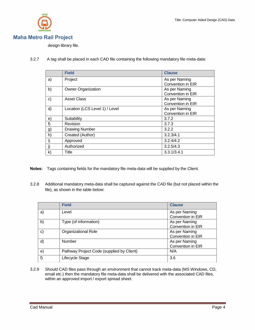
3.5.5 Scales used on drawings shall confirm to BS EN ISO 5455, preferred scales shown below:
Title: Computer Aided Design (CAD) Data
Maha Metro Rail Project
Cad Manual Page 7
Recommended Metric Scales
1:2 1:5 1:10
1:20 1:50 1:100
1:200 1:500 1:1000
1:250 1:5000 1:1250
1:2000 1:10000
1:2500

Title: Computer Aided Design (CAD) Data
Maha Metro Rail Project
Cad Manual Page 8
3.5.6 Terms and abbreviations not defined shall be clearly defined on the associated drawing sheet.
3.5.7 Line types
• They shall conform to the file of line types located in Support directory of the project • The scale of the line types shall be 1 whatever paper space scale is used • Line Styles will be accordance with the style defined in the CAD Modele.dwt file.the for example :
3.5.8 Frame and title Block
• Layout will be composed of two parts.
First, a block containing the attributes of the drawing: Titles, numbers, dates …and a table with
the list of all Xref used to produce the drawing.
The second part will be a reference file containing the non-amendable objects of the drawing:
Frame, logos, Project name ….
• These two parts will be set in the paper space, at scale 1=1 mm.
• The block will not be split.
• The reference file of the Title Block will not be merged.
• Only one title block in one file is permitted.
• One File = One Paper space drawing = One Title block
Title: Computer Aided Design (CAD) Data
Maha Metro Rail Project
Cad Manual Page 9
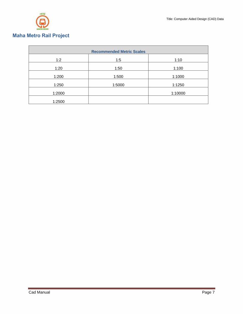
3.5.9 Drawing sheets shall state clearly the following information:
a) Asset Classification g) Purpose of Issue
b) Drawing number h) Revision
c) File name i) Scale(s)
d) Location j) Suitability
e) Originator k) Title
f) Project
3.5.10 Drawing definitions shall be presented to allow drawing renditions and printed drawings to be derived as an exact copy.
Note: i. If drawing renditions / printed drawings are intended to be displayed as monochrome, the drawing definition shall be presented in monochrome, not color.
3.6 Lifecycle stages
3.6.1 CAD files shall carry the meta-data of ‘Lifecycle Stage’, to indicate the stage within the Project that the contained information has been approved for use.
3.6.2 One of the following Lifecycle Stages shall be used:
• Initiation
• Concept Stage
• Preliminary Stage
• Detailed Design Stage
• Construction (Installation)
• Hanover
• Operations and Maintenance
3.7 Status
3.7.1 CAD files shall be assigned a status, consisting of:
a) Suitability (see 3.7.2); and
b) Revision (see 0).

Title: Computer Aided Design (CAD) Data
Maha Metro Rail Project
Cad Manual Page 10
3.7.2 Suitability Status
3.7.2.1 CAD files shall carry the meta-data of ‘suitability’, to indicate the approved use
of the contained information.
3.7.2.2 Suitability codes shall be one or two alpha-numeric and shall be reserved for
use with a specific phase of the collaboration process, as defined in the table
below:
Code Description Model Files
Drawing Renditions
Work in Progress (Non-Contractual)
S0 Non Verified Design The File is in Work in Progress, not be shared with others
yes yes
Shared (Non-Contractual)
S01 Coordination (for Use)
The file is shared and can be used by others for
the purpose of design coordination and / or MMRCL acceptance
yes yes
S02 For Comment
The file is shared and is to only be used, by others, to identify and communicate potential impacts of the change to the design
yes yes
Published (Contractual)
GFC Good for Construction The file contents has been accepted and verified by MMRCL for construction purposes.
yes yes
AB As Built The file contents have been accepted by MMRCL, as being verified as to what has been built/ installed.
yes yes
Note: i. ‘As Surveyed’ and ‘As Designed’ are additional to the requirements of BS1192. ‘For Information’ has been removed to prevent ambiguity around the suitability of use of that data / information.

Title: Computer Aided Design (CAD) Data
Maha Metro Rail Project
Cad Manual Page 11
3.7.3 Revision
3.7.3.1 CAD files shall carry the meta-data of ‘revision’, indicating the issue sequence of the contained information.
3.7.3.2 as with suitability codes, different sets of revision codes shall be reserved for use within
each section of the defined Common Data Environment (CDE) process.
3.7.3.3 Within ‘Work in Progress’, preliminary revisions shall be 1.1, 1.2, or 2.1, 2.2, etc. The suffix (.1, .2 etc.) is known as a ‘minor version’ and shall be used to track the iterative progress of the file prior to being approved for sharing.
3.7.3.4 CAD files approved for sharing shall carry a preliminary revision, 1.0, 2.0, 3.0, etc.
3.8 CAD File & layer naming
3.8.1 Names assigned with CAD files and layers within the CAD file shall be created by Joining together codes in the specified fields, in the specified order, using only the “-” Hyphen character, which is therefore not allowed in any code.
3.8.2 The only exceptions to 3.10.1 shall be the codes for ‘level’ and ‘description’
which are appended following an underscore “_”.
3.8.3 Codes shall be selected from field codes (defined within 3.13).
3.8.4 Codes shall not imply meaning that may be duplicated in other fields.
3.8.5 Characters shall be uppercase.
3.8.6 Codes shall be generated and governed by the MMRCL CAD Support Team.
Notes: i. CAD files and layer naming is compliant with BS1192. See 3.9 and 3.10.
3.8 CAD File naming convention
Please refer to EIR Documents for File Naming Convention.
Title: Computer Aided Design (CAD) Data
Maha Metro Rail Project
Cad Manual Page 12
3.10 CAD Layer naming convention
3.10.1 Layer names within CAD files shall be composed by joining the fields shown in the table below:
Title: Computer Aided Design (CAD) Data
Maha Metro Rail Project
Cad Manual Page 13
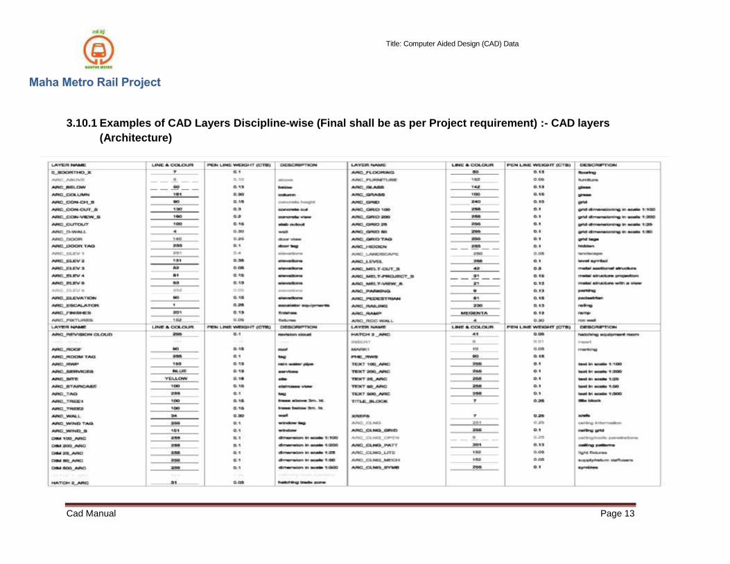
3.10.1 Examples of CAD Layers Discipline-wise (Final shall be as per Project requirement) :- CAD layers
(Architecture)

Title: Computer Aided Design (CAD) Data
Maha Metro Rail Project
Cad Manual Page 14
3.10.2 CAD layers (Architecture Landscaping)
Landscaping CAD Laying System
Title: Computer Aided Design (CAD) Data
Maha Metro Rail Project
Cad Manual Page 15
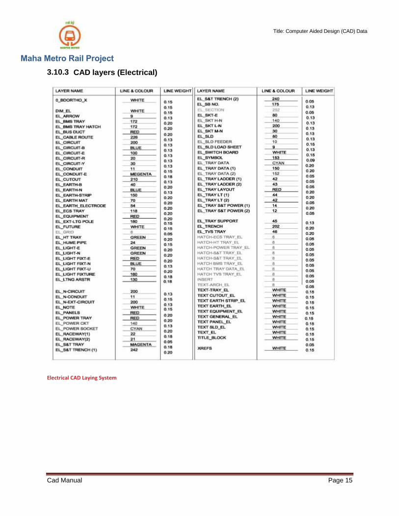
3.10.3 CAD layers (Electrical)
Electrical CAD Laying System

Title: Computer Aided Design (CAD) Data
Maha Metro Rail Project
Cad Manual Page 16
3.10.4 CAD layers (Fire Detection)
Fire Detection CAD Laying System
Title: Computer Aided Design (CAD) Data
Maha Metro Rail Project
Cad Manual Page 17
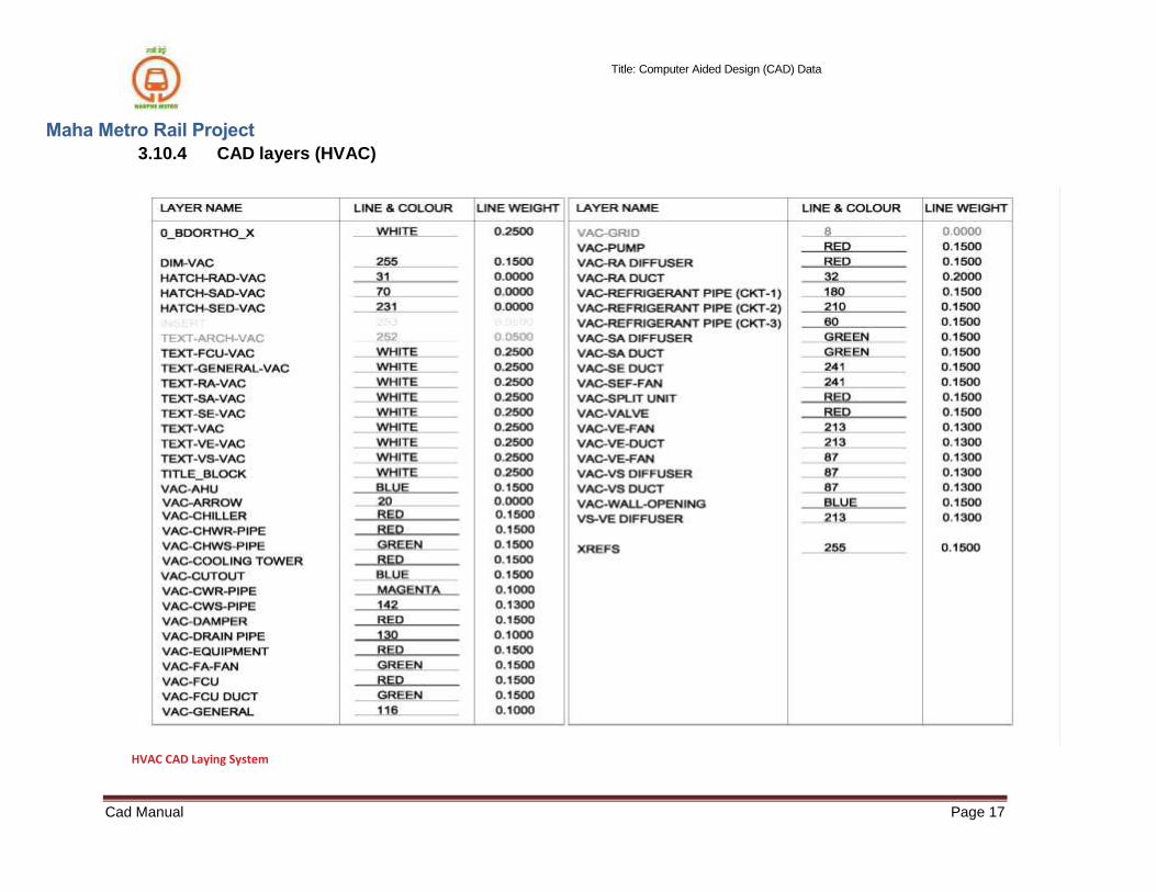
3.10.4 CAD layers (HVAC)
HVAC CAD Laying System

Title: Computer Aided Design (CAD) Data
Maha Metro Rail Project
Cad Manual Page 18
3.10.5 CAD layers (Plumbing)
Plumbing CAD Laying System

Title: Computer Aided Design (CAD) Data
Maha Metro Rail Project
Cad Manual Page 19
3.10.6 CAD layers (Highways)
Highway CAD Laying System
Title: Computer Aided Design (CAD) Data
Maha Metro Rail Project
Cad Manual Page 20
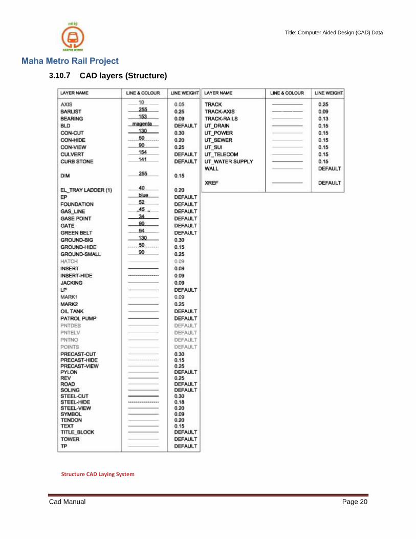
3.10.7 CAD layers (Structure)
Structure CAD Laying System

Title: Computer Aided Design (CAD) Data
Maha Metro Rail Project
Cad Manual Page 21
3.11 APPENDIX 1 – CAD Symbols & Blocks
3.11.1 ARCHITECTURE SYMBOLS & ABBREVIATIONS
Architecture Symbols & Abbreviation

Title: Computer Aided Design (CAD) Data
Maha Metro Rail Project
Cad Manual Page 22
3.11.2 ELECTRICAL SYMBOLS & ABBREVIATIONS (SH-1)
Electrical Symbols & Abbreviation (Sh-1)
Title: Computer Aided Design (CAD) Data
Maha Metro Rail Project
Cad Manual Page 23
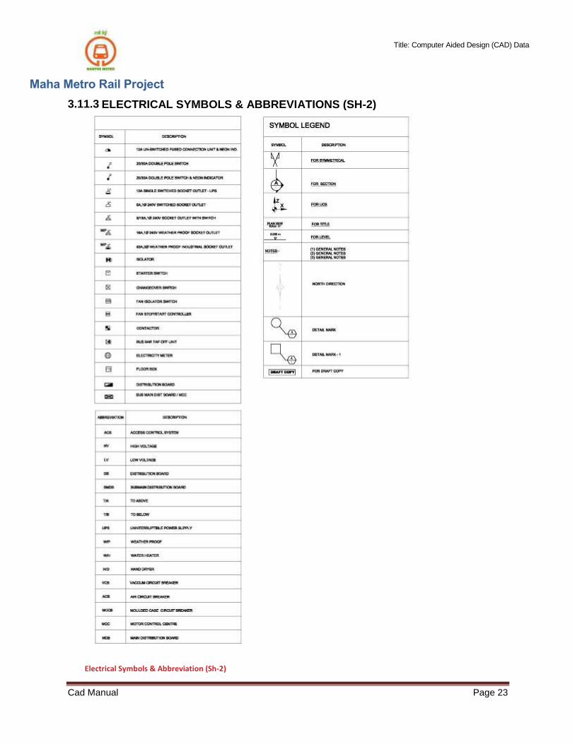
3.11.3 ELECTRICAL SYMBOLS & ABBREVIATIONS (SH-2)
Electrical Symbols & Abbreviation (Sh-2)

Title: Computer Aided Design (CAD) Data
Maha Metro Rail Project
Cad Manual Page 24
3.11.4 FIRE DETECTION AND FIRE FIGHTING SYMBOLS & ABBREVIATIONS (SH-1)
Fire Detection & Fire Fighting Symbols & Abbreviation (Sh-1)

Title: Computer Aided Design (CAD) Data
Maha Metro Rail Project
Cad Manual Page 25
3.11.5 FIRE DETECTION AND FIRE FIGHTING SYMBOLS & ABBREVIATIONS (SH-2)
Fire Detection & Fire Fighting Symbols & Abbreviation (Sh-2)

Title: Computer Aided Design (CAD) Data
Maha Metro Rail Project
Cad Manual Page 26
3.11.6 HVAC SYMBOLS & ABBREVIATIONS (SH-1)
HVAC Symbols & Abbreviation (Sh-1)

Title: Computer Aided Design (CAD) Data
Maha Metro Rail Project
Cad Manual Page 27
3.11.7 HVAC SYMBOLS & ABBREVIATIONS (SH-2)
HVAC Symbols & Abbreviation (Sh-2)
Title: Computer Aided Design (CAD) Data
Maha Metro Rail Project
Cad Manual Page 28
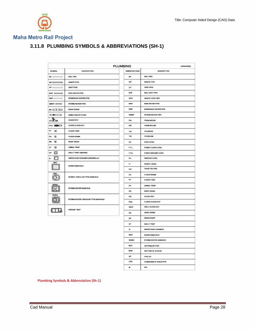
3.11.8 PLUMBING SYMBOLS & ABBREVIATIONS (SH-1)
Plumbing Symbols & Abbreviation (Sh-1)
Title: Computer Aided Design (CAD) Data
Maha Metro Rail Project
Cad Manual Page 29
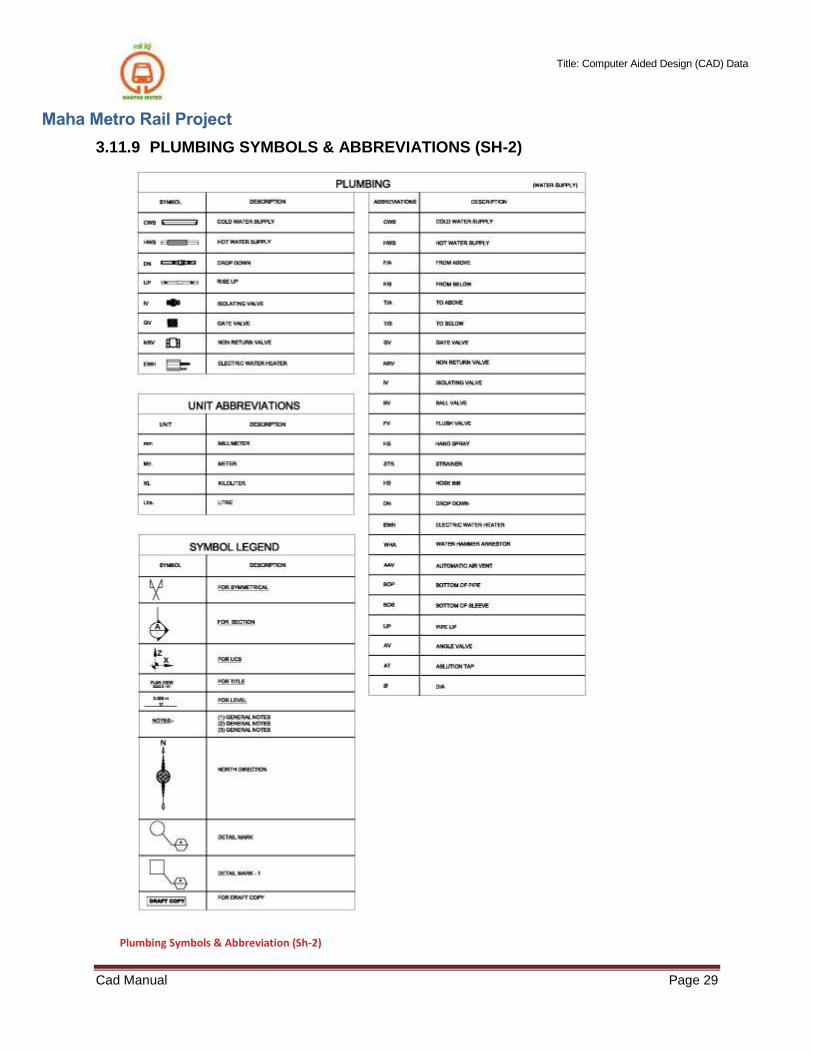
3.11.9 PLUMBING SYMBOLS & ABBREVIATIONS (SH-2)
Plumbing Symbols & Abbreviation (Sh-2)
Title: Computer Aided Design (CAD) Data
Maha Metro Rail Project
Cad Manual Page 30
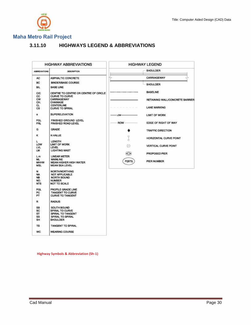
3.11.10 HIGHWAYS LEGEND & ABBREVIATIONS
Highway Symbols & Abbreviation (Sh-1)

Title: Computer Aided Design (CAD) Data
Maha Metro Rail Project
Cad Manual Page 31
3.11.11 CIVIL (STRUCTURE) SYMBOLS

Title: Computer Aided Design (CAD) Data
Maha Metro Rail Project
Cad Manual Page 32
4 Responsibilities
4.1 Author
4.1.1 Accuracy of graphical and non-graphical elements within a CAD file.
4.1.2 Compliance with this standard.
4.2 Approver
4.2.1 Approving CAD files to be shared and used for the suitability (see 3.7.2) indicated.
4.2.2 Maintaining an audit trail to capture the checks and reviews carried out to gain approvals.
4.3 Authorizer
4.3. 1On behalf of MMRCL, authorizing (accept / reject) CAD files submitted to MMRCL for publishing for the suitability (see 3.7.2) indicated.
4.4 MMRCL CAD Support Team
4.4.1 Generation and governance of field codes.
4.4.2 Supply and management of MMRCL CAD data, resources and licensed mapping.
4.5 MMRCL Principal Infrastructure Protection Engineer
4.5.1 Approving external requests to MMRCL for CAD data, not originating from within an MMRCL project.
4.6 MMRCL Procurement Agent
4.6.1 The MMRCL Procurement Agent shall be responsible for incorporating the requirements of this engineering standard in any contract to which it is relevant and shall stipulate that a programme of audits is implemented by the contractor which ensures that these requirements are complied with.
5 Supporting information
5.1 Background
5.1.1 The requirements within this document shall be read in conjunction with the reference documents listed in 6.1.1.
5.1.2 If you need any technical assistance with any of the requirements within this document, you can contact the MMRCL CAD Support Team at
Title: Computer Aided Design (CAD) Data
Maha Metro Rail Project
Cad Manual Page 33
6 References
6.1 References
6.1. Refer to EIR
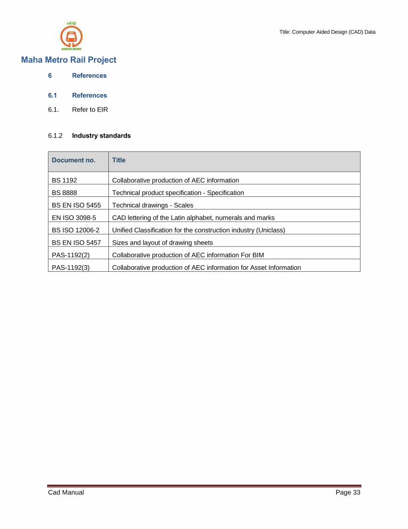
6.1.2 Industry standards
Document no.
Title
BS 1192 Collaborative production of AEC information
BS 8888 Technical product specification - Specification
BS EN ISO 5455 Technical drawings - Scales
EN ISO 3098-5 CAD lettering of the Latin alphabet, numerals and marks
BS ISO 12006-2 Unified Classification for the construction industry (Uniclass)
BS EN ISO 5457 Sizes and layout of drawing sheets
PAS-1192(2) Collaborative production of AEC information For BIM
PAS-1192(3) Collaborative production of AEC information for Asset Information

Title: Computer Aided Design (CAD) Data
Maha Metro Rail Project
Cad Manual Page 34
6.2 Abbreviations
The following abbreviations are created:
a) Within MMRCL Glossary of Terms (a Category 1 Standard); b) From published sources that are clearly identified.
Abbreviation Definition Source
AEC Architectural, Engineering and Construction a
CAD Computer Aided Design a
MMRCL Maha Metro Rail Corporation Limited a
OS Ordnance Survey a
6.3 Definitions
Topic specific definitions
Term Definition
Asset Class Highest level of classification of London Underground’s Engineering Assets, as defined in CAT 1 Standard S1041
CAD Computer Aided Design) File
Electronic file produced by a CAD application (such as MicroStation or AutoCAD). Examples of CAD files include Drawing Definitions and Model files.
Classification Systematic arrangement of design and construction activities and assets, including construction elements, systems and products
Common Data Environment (CDE)
A designated environment with a defined process used to manage all relevant information. A CDE may comprise of one or more systems supporting a consistent collaborative approach.
Composite Model
Computer Aided Design (CAD) file that contains one or more Model Files, as references, for the purpose of spatial coordination; there is no ‘live’ geometry within the file. It may form part of a Drawing Definition.
Data Set of digital values stored, but not yet interpreted or analysed (un-processed), in a form that is convenient to move or process. Data is generally represented in a structured and often tabulated form (rows and columns). ‘Raw Data’ is a relative term and therefore not used.
DGN Proprietary Bentley Systems file format
Document Information recorded for a specific purpose, providing a means tocommunicate the briefing, design, construction, operation, maintenance or decommissioning of an asset. This includes, but is not limited to, correspondence, Drawing Renditions, schedules, specifications, calculations, spreadsheets. Note: Documentation must either be in an immutable format or incorporate a means of controlling changes.

Title: Computer Aided Design (CAD) Data
Maha Metro Rail Project
Cad Manual Page 35
Term Definition
Drawing Definition A CAD file created solely for the purpose of creating a Drawing Rendition or Printed Drawing. The graphical content of the drawing definition is contained in other CAD files (e.g. Model Files and/or Composite Models) which are attached as References. Only annotation and dimensions are ‘live’ within the Drawing Definition file. Examples may include As-built Drawing Definitions.
Drawing Rendition Electronic file, in an immutable format such as PDF, derived from a Drawing Definition. Examples may include As-built Drawing Renditions.
Drawing Sheet CAD file containing the graphics of a blank drawing border and title block, of Predefined paper sizes. Used as a reference by all drawing definitions.
Information Data which has been interpreted and processed (such as formatting andprinting) to take on meaning in some context for its intended receiver.
Layer Synonymous with the level functionality in the DWG File format.
Level Floor level within a building (refer to S0135, Location Coding System)
Meta-data ‘Data about the data’. Information about one or more aspects of certain items content. For example: size of document, date created etc.
Model File A Computer Aided Design (CAD) file which consists of geometry that represents the physical characteristics (may also include functional characteristics) of the works, produced at a scale of 1:1. It may form part ofthe Composite Model and/or Drawing Definition.
Model rendition An immutable file, in a format such as PDF, which is derived from a Model File or Composite Model.
Newlyn Mean sea level (MSL) calculated from observation taken at Newlyn, Cornwall and used as the official basis for height calculation.
Printed Drawing Static, hard-copy document, derived from a Drawing Definition (as an exact copy) or Drawing Rendition.
Project A unique set of co-ordinated activities, with definite starting and finishing points, undertaken by an individual or organization to meet specific objectives within defined schedule, cost and performance parameters.
Reference An Auto Cad/Bentley MicroStation term meaning a CAD file attached to another CAD file such that all or part of its graphical content is visible but not editable in the file to which it is attached.
Status Defines the suitability of information.
Spatial Data Geometry aligned to the physical location of an asset, to a specified grid system.
Tag An Auto Cad /Bentley MicroStation term meaning a non-graphical attribute attached to an element within a CAD file.

Title: Computer Aided Design (CAD) Data
Maha Metro Rail Project
Cad Manual Page 36
6.4 Technical content manager
Paragraph number
Technical content manager
All Head of Engineering Information
6.5 Document history
Issue no Date Changes Author
A1 October 2016 Authorised for use