Embed Size (px)
Citation preview

Catalyst management:
regeneration, reactivation, ex-situ
sulfuration technologies
Gabriella Fogassy
20 March 2013, Sisak

WHERE WE ARE LOCATED?
2
PARIS
La Voulte-sur-Rhône, France

EURECAT IN THE WORLD
Eurecat USPasadena/TX
Eco-RigenGela, Italy
Al-Bilad Catalyst Al-Jubail, Saudi
Arabia
Eurecat IndiaCatalyst Services Jhagadia, Gujarat,
IndiaPetroval USHouston/TX
Tricat USMcAlester/OK
Petroval SASt Romain de Colbosc
Petroval APEurecat Rep. Office
Singapore
Americas Europe Middle East Asia
3
TricatBitterfeld, Germany
Eurecat FranceLa Voulte-sur-Rhône

STANDARDS & VALUES
4
Responsible Care Program
Quality ISO 9001 certification
Environmental ISO 14001 certification
Safety OHSAS* 18001 certification or equivalent
(*Occupational Health and Safety Assessment Series)
Our values:
❑ Innovation
❑ Customer satisfaction
❑ Confidentiality
❑ Ethics

SERVICES, PRODUCTS & TREATMENT
Regeneration /React Sulfiding/Activation
Recycling(metal recovery)
Toll-processing / Manufacturing
Logistics
Reactor Management Services (RMS) / Field services (Petroval )
(Re)sale / Trading

6
UNIT OPERATION/CATALYST LIFE CYCLE
In-situsulfiding
ActivityDp
LoadingFresh Startup RunRegenerationReactivation
Metalreclaim
Unloading
REUSECASCADING
POOLRESALE

7
UNIT OPERATION/CATALYST LIFE CYCLE
In-situsulfiding
ActivityDp
LoadingFresh Startup RunRegenerationReactivation
Metalreclaim
Unloading
REUSECASCADING
POOLRESALE
8
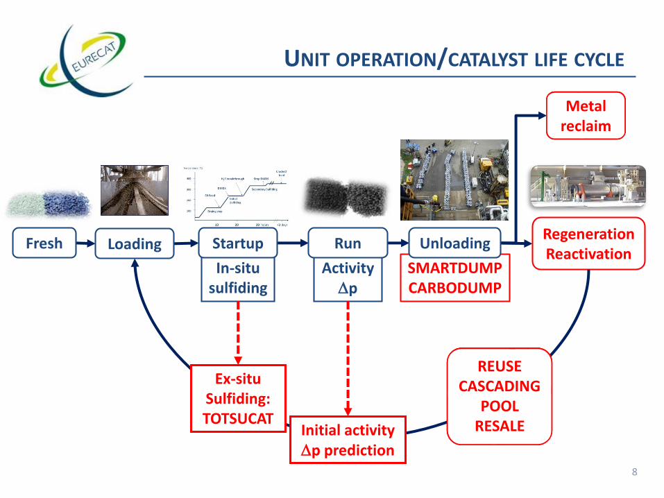
UNIT OPERATION/CATALYST LIFE CYCLE
In-situsulfiding
ActivityDp
LoadingFresh Startup RunRegenerationReactivation
Metalreclaim
REUSECASCADING
POOLRESALE
SMARTDUMPCARBODUMP
Ex-situSulfiding:TOTSUCAT
Initial activityDp prediction
Unloading

9
UNIT OPERATION/CATALYST LIFE CYCLE
In-situsulfiding
ActivityDp
LoadingFresh Startup RunRegenerationReactivation
Metalreclaim
REUSECASCADING
POOLRESALE
SMARTDUMPCARBODUMP
Ex-situSulfiding:TOTSUCAT
Initial activityDp prediction
Unloading

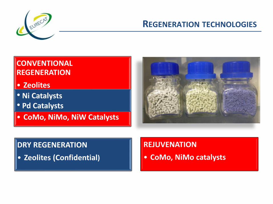
REGENERATION TECHNOLOGIES
CONVENTIONALREGENERATION
• Zeolites
• Ni Catalysts
• Pd Catalysts
• CoMo, NiMo, NiW Catalysts
REJUVENATION
• CoMo, NiMo catalysts
DRY REGENERATION
• Zeolites (Confidential)
REGENERATION TECHNOLOGIES
CONVENTIONALREGENERATION
• Zeolites
• Ni Catalysts
• Pd Catalysts
• CoMo, NiMo, NiW Catalysts
REJUVENATION
• CoMo, NiMo catalysts
DRY REGENERATION
• Zeolites (Confidential)
• Ni Catalysts• Pd Catalysts

DEACTIVATION MECHANISMS OF HPC
1. Reversible poisoning:– Carbon: 5-25%– Basic nitrogen (Hydrocracking)From side reactions
2. Structural modifications:– Sintering of metallic particles– Migrations and/or losses of active species– Structure changesFunction of operating conditions
3. Irreversible poisoning:– Metallic contaminants (V, Fe,
As, Hg…)– Silicon, sodium… – Sulfur (Ni…)
Feed composition

Sampling
HPC TREATMENT
Reporting to customer13
Activity testing (lab )
Physico-chemical characterization Activity testing (ind)
Lab regeneration
Physico-chemical characterization
Feed-back to customer
Plant regeneration
Dp prediction

Sampling
HPC TREATMENT
Reporting to customer14
Activity testing (lab )
Physico-chemical characterization Activity testing (ind)
Lab regeneration
Physico-chemical characterization
Feed-back to customer
Plant regeneration
Dp prediction

Standard
sampling procedure
(for each bed)
15-30 samples are taken and
mixed together and
homogenized before
characterization
Dedicated SAS
sampling procedure
(for each bed)
15-30 samples are taken and
all samples are kept separated
for individual characterization
15
SAMPLING/ANALYSIS
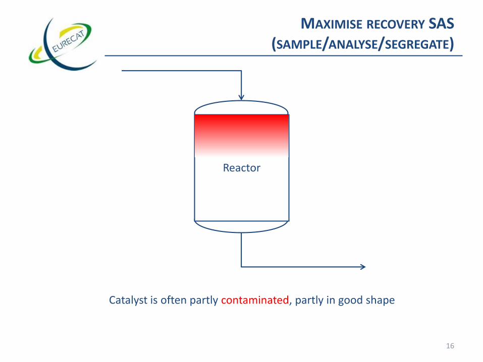
Catalyst is often partly contaminated, partly in good shape
Reactor
MAXIMISE RECOVERY SAS (SAMPLE/ANALYSE/SEGREGATE)
16

Catalyst is often partly contaminated, partly in good shape
SAS: SAMPLE/ANALYSE/SEGREGATE
17❑ Allows to trace metals contamination vs height in reactor.

Catalyst is often partly contaminated, partly in good shape
SAS: SAMPLE/ANALYSE/SEGREGATE
18❑ Allows to trace metals contamination vs height in reactor.

Catalyst is often partly contaminated, partly in good shape
SAS: SAMPLE/ANALYSE/SEGREGATE
19❑ Allows to trace metals contamination vs height in reactor.

Catalyst is often partly contaminated, partly in good shape
SAS: SAMPLE/ANALYSE/SEGREGATE
20❑ Allows to trace metals contamination vs height in reactor.

SAS: SAMPLE/ANALYSE/SEGREGATE
21❑ Allows to trace metals contamination vs height in reactor.

0
20
40
60
80
100
120
140
160
180
200
Surf
ace
Are
a [m
2/g
]
0.00
1.00
2.00
3.00
4.00
5.00
6.00
7.00
8.00
9.00
10.00
Van
adiu
m [w
t%]
Reactor height (drum number 1 – N)
Vanadium spec
Must recycle
Can regenerate!
SAS: SAMPLE/ANALYSE/SEGREGATE
22
❑ Drums/bins should be numbered during unloading!!!
❑ Allows to trace metals contamination vs height in reactor.

SAS: SAMPLE/ANALYSE/SEGREGATE
23
Case study of 96 tons reactor
❑ Average analyses slightly off-spec
❑ Refiner wanted to send batch for metals recovery.
❑ SAS pointed out contamination was very local
❑ 75% of catalyst could be recovered
❑ 1.3 M$ savings
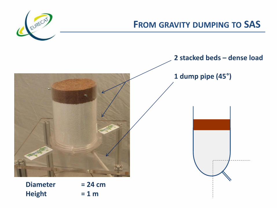
2 stacked beds – dense load
1 dump pipe (45°)
45°Diameter = 24 cmHeight = 1 m
FROM GRAVITY DUMPING TO SAS

Front view
Side view
FROM GRAVITY DUMPING

Dig outConical shape
SAS
Gravity Unloading
TO SAS
❑ After Gravity dump, SAS can trace back the position of the catalyst in the reactor.

3Q
N° BINSAs
(wt%)V
(wt%)Fe
(wt%)Si
(wt%)Na
(wt%)C spent(wt%)
S spent(wt%)
C lab reg(wt%)
S lab reg(wt%)
SA(m²/g)
2-6-10-12-14 0.25 <0.01 0.07 0.25 0.08 4.8 12.8 0.1 1.5 149
3Q
N° BINSAs
(wt%)V
(wt%)Fe
(wt%)Si
(wt%)Na
(wt%)C spent(wt%)
S spent(wt%)
C lab reg(wt%)
S lab reg(wt%)
SA(m²/g)
42-46-48-50 <0.01 <0.01 0.06 0.03 <0.05 9.0 14.2 0.1 0.8 156
KF757
N° BINSAs
(wt%)V
(wt%)Fe
(wt%)Si
(wt%)Na
(wt%)C spent(wt%)
S spent(wt%)
C lab reg(wt%)
S lab reg(wt%)
SA(m²/g)
Lmm(mm)
%grains < 1.5mm
%grains< 2.0mm
2 0.15 0.00 0.12 0.15 0.09 10.8 13.6 0.1 0.6 141 2.67 6 22
4 0.51 0.00 0.13 0.17 0.07
6 0.24 0.00 0.13 0.17 0.11 9.5 14.3 0.1 0.8 143 3 4 18
8 0.37 0.00 0.14 0.17 0.14
10 0.13 0.00 0.11 0.15 0.08 9.1 13.9 0.1 0.6 142 3.04 2 10
14 0.03 0.00 0.10 0.15 0.08 9.5 13.5 0.1 0.6 142
18 0.02 0.00 0.08 0.16 0.06 10.2 14.2 0.1 0.4 151 2.84 4 15
22 0.01 0.00 0.08 0.15 0.08 10.9 14.1 0.1 0.3 154
26 0.00 0.00 0.07 0.14 0.05 11.0 13.7 0.1 0.4 160 3.31 3 9
30 0.00 0.00 0.06 0.15 0.05 11.0 13.8 0.1 0.3 162
34 0.00 0.00 0.06 0.14 0.04 10.3 14.0 0.1 0.3 152 2.85 4 15
38 0.00 0.00 0.07 0.15 0.05 11.4 14.1 0.1 0.3 162
42 0.00 0.00 0.06 0.16 0.05 12.0 13.4 0.1 0.2 158 3.00 5 14
46 0.00 0.00 0.06 0.15 0.04 12.0 14.0 0.1 0.3 153
50 0.00 0.00 0.06 0.15 0.05 12.0 13.7 0.1 0.3 160 2.66 10 26
Average 0.10 0.00 0.09 0.15 0.07 10.7 13.9 0.1 0.4 152 2.89 5 16
TO SAS
27
Material recycled
Material regenerated/REACTivated

Carbon
Sulfur
Labregenerated
HPCcatalyst
Surface area
BCS (Bulk Crushing Strength)and/or
SCS (Side Crushing Strength)
Average length
PSD (Particle Size Distribution)
Poisons (As, V, Fe, Si, Na, Ni,…)
LAB REGENERATED CATALYST ANALYSIS
Abrasion loss

Sampling
HPC TREATMENT
Reporting to customer29
Activity testing (lab )
Physico-chemical characterization Activity testing (ind)
Lab regeneration
Physico-chemical characterization
Feed-back to customer
Plant regeneration
Dp prediction
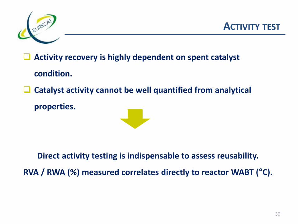
ACTIVITY TEST
❑ Activity recovery is highly dependent on spent catalyst
condition.
❑ Catalyst activity cannot be well quantified from analytical
properties.
Direct activity testing is indispensable to assess reusability.
RVA / RWA (%) measured correlates directly to reactor WABT (°C).
30 30

ACTIVITY VS SURFACE AREA KF757
31No relevant metals contamination on every batch

ACTIVITY TEST
32

MTU OVERWIEV
Capacity: 80 samples/month
Sampler(and degassing section)
HDS – ULSD (10 -100 ppm S)
33
Furnace and 10 reactors in parallel

Sampling
HPC TREATMENT
Reporting to customer34
Activity testing (lab )
Physico-chemical characterization Activity testing (ind)
Lab regeneration
Physico-chemical characterization
Feed-back to customer
Plant regeneration/sampling
Dp prediction

Sampling
HPC TREATMENT
Reporting to customer35
Activity testing (lab )
Physico-chemical characterization Activity testing (ind)
Lab regeneration
Physico-chemical characterization
Feed-back to customer
Plant regeneration/sampling
Dp prediction

REGENERATION PARAMETERS OF HPC
36
2 Commercial Hydrotreating catalyst - CoMo on Al2O3
Tailor-made recipes for each individual catalyst
(m2/g) (m2/g)
Carbon
Sulfur
T1 T3T2 T4 T5 T7 T8T6
0
5
10
15
20
Temp (°C)
wt
%
0
50
100
150
200
250
300
SA
(m²/g
)
C (CoMo-1) C (CoMo- 2)
S (CoMo-1) S (CoMo-2)SA (CoMo-1) SA (CoMo-2)

ROTO-LOUVRE
Maximum activity recovery:
❑homogeneous regeneration
❑strict temperature control
❑rapid heat and H2O/SO2 removal
37

REGNERATION FLOW SHEET
38
Regeneration ovenDust
(<1mm) Fines (<1mm)
Gas
Air
Srubber
Spent catalyst
Inerts
3mm (diameter) catalyst
1.3mm (diameter) catalyst❑ Continuous process
❑ High activity recovery (> 95 % SA retention)
❑ Fines guaranteed to be less than 1 wt%
❑ Fine-tuned to each different catalyst
❑ Catalyst evaluation (QC)

PLANT REGENERATION
Fee
din
g &
sie
vin
g
We
igh
tin
g
Siev
ing,
(le
ngt
h g
rad
ing)
,p
acka
gin
g &
we
igh
ing
Re
gen
ere
atio
n

Sampling
HPC TREATMENT
Reporting to customer40
Activity testing (lab )
Physico-chemical characterization Activity testing (ind)
Lab regeneration
Physico-chemical characterization
Feed-back to customer
Plant regeneration/sampling
Dp prediction
Sampling
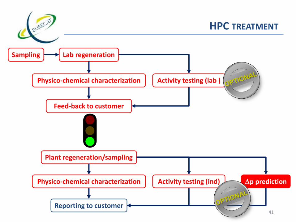
HPC TREATMENT
Reporting to customer41
Activity testing (lab )
Physico-chemical characterization Activity testing (ind)
Lab regeneration
Physico-chemical characterization
Feed-back to customer
Plant regeneration/sampling
Dp prediction

❑ Eurecat has developed unique pressure drop measurement to predict mixed phase delta P in refinery reactor conditions.
Catalyst Performance: Pressure drop
Commercial
DPref (bar)PredictedDP
(bar)
EurecatLab gas phase DPref measurement+ Lab gas phase DP measurement
+ Correlation

❑ Tool has been validated in refinery units (multibed, dense/sock):
Catalyst Performance: Pressure drop
2008 loading scheme = reference 2011 loading scheme
Cat 1Dense loading
Cat 2 Dense loading
Cat 2 Dense loading
Cat 2 Dense loading
Cat 2 Dense loading
Cat 2 Dense loading
Reactor A Reactor B
Cat 3Sock loading
Cat 3Sock loading
Cat 3Sock loading
Cat 3Sock loading
Cat 4Dense loading
Cat 4Dense loading
Reactor A Reactor B
Eurecat laboratory data
Ind
ust
rial
un
it d
ata

PARTICULE SIZE DISTRIBUTION VS PRESSURE DROP
44
0
1
2
3
4
5
6
7
8
9
PS
D (
% v
ol)
Lenght (mm)
Particle Size Distribution (PSD)
Average lenght: 2.4 mmParticles <1.5 mm: 7 wt%Particles <2 mm: 31 wt%
Dp regeneratedcatalyst: 1.22 bar
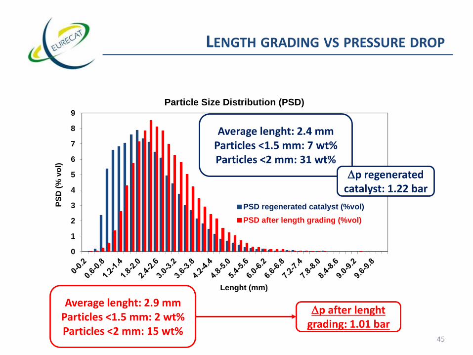
LENGTH GRADING VS PRESSURE DROP
45
0
1
2
3
4
5
6
7
8
9
PS
D (
% v
ol)
Lenght (mm)
Particle Size Distribution (PSD)
PSD regenerated catalyst (%vol)
PSD after length grading (%vol)
Dp after lenghtgrading: 1.01 bar
Average lenght: 2.9 mmParticles <1.5 mm: 2 wt%Particles <2 mm: 15 wt%
Average lenght: 2.4 mmParticles <1.5 mm: 7 wt%Particles <2 mm: 31 wt%
Dp regeneratedcatalyst: 1.22 bar

Sampling
HPC TREATMENT
Reporting to customer46
Activity testing (lab )
Physico-chemical characterization Activity testing (ind)
Lab regeneration
Physico-chemical characterization
Feed-back to customer
Plant regeneration/sampling
Dp prediction

1XXXX/A KF757 3Q Comments: PO number:
1XXXX/B KF767 1.5E FB 66-68 : 40 wt % dust End of treatment: 31/1/2013
Regeneration mass balance
Inerts: (kg) 3528 16 drum(s)
Unregenerated material: 53201 Regenerated catalyst: net: (kg)
net: (kg) KF757\3Q 998 1 BB
57983 68 bins KF767 1.5E 42100 43 BB
Dust: (kg) 1254 7 drum(s) Fines: (kg) 368 11 drum(s)
Regeneration analysis results
1XXXX/B KF767 1.5E Spent: Lab regen: Spec: Regen: Notes: Metals contaminants: (wt%)Notes: Notes:
LOI (wt%): 18.3 - - - As: <0.01 RVA (%): 92 vs fresh
Smoke test: Yes - - - V: <0.01 RWA (%): 98 vs fresh
HC/other volatiles (wt%): 2.9 - - - Fe: 0.2 Dp (bar): 1.01
C (wt%): 14.2 0.1 0.5 0.1 Si: 0.1
S (wt%): 12.0 0.4 0.9 0.5 Na: 0.11
Surface area (m²/g): - 140 137 140 Ni: <0.01
BCS (MPa): - 1.60 1.44 1.58 Regenerated densities: Notes:
Average length (mm): - 3.0 2.8 3.0 CBD (t/m³): 0.843
< 2 mm (%): - 17 20 15 SD (t/m³): 0.784
< 1.5 mm (%): - 6 10 5 PDLD (t/m³): 0.903
Fines (wt%): - - - <0.1 VF (-): 0.325
Additional analysis results can be published via a stock database directly accessible via the Internet
1XXXX/A KF757 3Q Spent: Lab regen: Spec: Regen: Notes: Metals contaminants: (wt%)Notes:
LOI (wt%): 18.3 - - - As: <0.01
Smoke test: Yes - - - V: 0.01
HC/other volatiles (wt%): - - - Fe: 0.12
C (wt%): 14.1 0.1 - 0.1 Si: 0.15
S (wt%): 12.7 0.3 - 0.8 Na: 0.15
Surface area (m²/g): - 176 - 170 Ni: <0.01
BCS (MPa): - - - 1.2 Regenerated densities: Notes:
Average length (mm): - - - 4.8 CBD (t/m³): 0.727
< 2 mm (%): - - - 1 SD (t/m³): 0.676
< 1.5 mm (%): - - - 0 PDLD (t/m³): 0.801
Fines (wt%): - - - <0.1 VF (-): 0.382
EURECAT France
E-mail : [email protected] - Website: www.eurecat.fr
Tel : 33.4.75.62.04.02 - Fax : 33.4.75.85 32.69
ZI Jean-Jaurès - B.P. 45 - 121, Avenue Marie Curie - 07800 LA VOULTE-SUR-RHÔNE - FRANCE
Regen/Lab REACTTM
:
REGENERATIONInitial
screening Final screening
47
Mass balance
Loading parameters
Performance prediction
Catalyst characteristic
Regeneration report

Sampling
HPC TREATMENT
Reporting to customer48
Activity testing (lab )
Physico-chemical characterization Activity testing (ind)
Lab regeneration/reactivation
Physico-chemical characterization
Feed-back to customer
Plant regeneration/sampling
Dp prediction
Plant reactivation/sampling
Physico-chemical characterization

REACTIVATION: STARS CATALYST
49E. Brevood, Catalysts Courier 60 (2005) 4.S. Eijsbouts, A.A. Battiston, G.C. van Leerdam, Catal. Today 130 (2008) 361.
STEM-EDX maps of Co (red) and Mo (green)TEM micrograph of CoMo catalyst
Regenerated
Regenerated
REACTivated
REACTivated
Redispersion of the active phase

Experience: more than25 000 tons delivered
EURECAT REACTTM STEPS
RegeneratedSTARS
Catalyst
Fines
REACT
Sampling& analysis
Sieving
Packing &weighting
REACTSTARS
CatalystREACT recipiecannot bedisclosed

Comments: PO number:
1XXXX/A KF767 1.5E
End of treatment:
1/2/2013
Rejuvenation mass balance
Oxidic catalyst: REACT™ catalyst:
net: (kg) net: (kg)
42100 43 BB 50054 43 BB
Rejuvenation analysis results
1XXXX/A KF767 Specs:REACT™: Notes: REACT™ densities: Notes: REACT™ : Notes:
C (wt%): - - CBD (t/m³): 1.039 RVA (%): 95 vs fresh
S (wt%): - - SD (t/m³): 0.966 RWA (%): 101 vs fresh
Surface area (m²/g): - 144 PDLD (t/m³): 1.111 Dp (bar): 1.04
Average length (mm): 2.8 2.85 VF (-): 0.338
< 2 mm (%): 20 19
< 1.5 mm (%): 10 6
Fines (wt%): <1.0 0.2
BCS (MPa): - 1.55
EURECAT France
ZI Jean-Jaurès - B.P. 45 - 121, Avenue Marie Curie - 07800 LA VOULTE-SUR-RHÔNE - FRANCE
Tel : 33.4.75.62.04.02 - Fax : 33.4.75.85 32.69
E-mail : [email protected] - Website: www.eurecat.fr
REACT™ REJUVENATION
51
Mass balance
Loading parameters
Performance prediction
Catalyst characteristic
REACT report
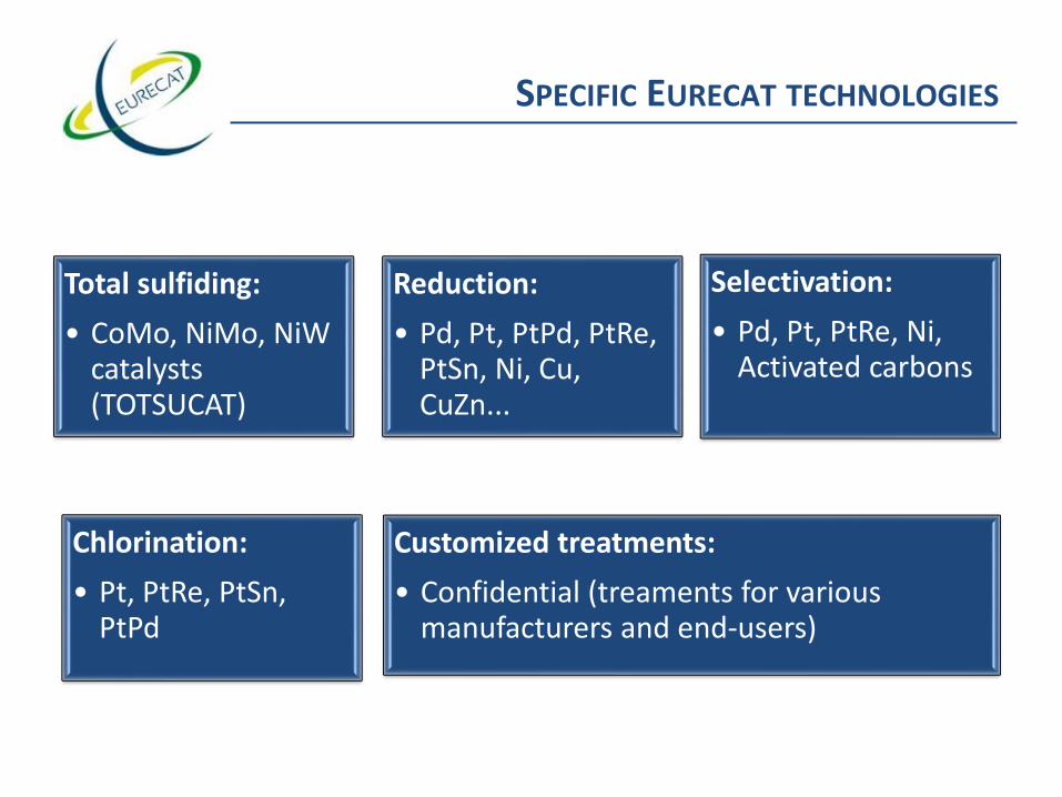
SPECIFIC EURECAT TECHNOLOGIES
Total sulfiding:
• CoMo, NiMo, NiWcatalysts (TOTSUCAT)
Reduction:
• Pd, Pt, PtPd, PtRe, PtSn, Ni, Cu, CuZn...
Selectivation:
• Pd, Pt, PtRe, Ni, Activated carbons
Chlorination:
• Pt, PtRe, PtSn,PtPd
Customized treatments:
• Confidential (treaments for various manufacturers and end-users)
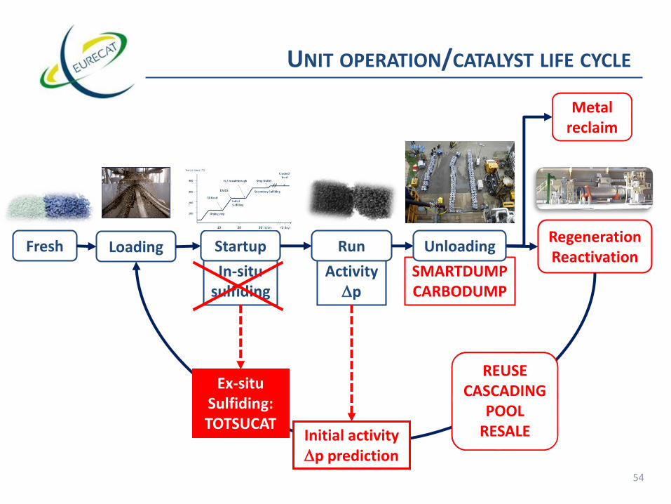
54
In-situsulfiding
ActivityDp
UNIT OPERATION/CATALYST LIFE CYCLE
LoadingFresh Startup RunRegenerationReactivation
Metalreclaim
SMARTDUMPCARBODUMP
Ex-situSulfiding:TOTSUCAT
Initial activityDp prediction
Unloading
REUSECASCADING
POOLRESALE
Ex-situSulfiding:TOTSUCAT

Temperature (°C)
400
300
200
100
10 20 30 hours +3 days
DMDS
Crackedfeed
Drying step
H2S breakthrough
Secondary Sulfiding
Stop DMDS
•SR Feed + DMDS at 80-150°C•Monitor H2S at outlet •Sulfide at 315-350°C•Sulfiding 3 days of SR feed
Initial Sulfiding
SR Feed
DMDS smell?
Obtain/store SR feed?
DMDS skid failure?
H2S sampling?
Amine unit overload?
Enough hydrogen?
RG compressor failure?
H2S induced corrosion?
Activation procedure
24h coverage?
Correct sulfiding
temperature?
Stripper flooding?
Activation exotherm?
Lose sulfur off the cat?
Catalyst reduction?
Catalyst activity ???
STARTUP WITH IN-SITU SULFIDING
LIQUID PHASE WITH SR FEEDH2S poisoning downstream?

OXYDIC CATALYST
IN-SITUSULFIDING
H2
+ -S-+ heat
H2
+ -S-+ heat
TOTSUCAT™
START-UP
START-UP
IN-SITUACTIVATION
H2
+ heat
START-UP
“PRE-SULFURIZATION”
LOADING
-S-
CATALYST SULFIDING

TOTALLY SULFIDED CATALYST (TOTSUCAT) VS
PRESULPHIDING (ACTICAT, SULFICAT…)
TOTSUCAT™ Presulphiding
Catalyst delivered already at full activity? YES NO
In situ activation required? NO YES
Sulphiding conditions? Optimized for each catalyst
type
Fixed by in situ procedure
Typical start up time 8h 24h+
Need to perform final sulphiding step at 320-350°C
(CoMo/NiMo)?
NOT APPLICABLE YES
Activation exotherm? NOT APPLICABLE YES
Additional H2 required for activation? NOT APPLICABLE YES
Typical H2S level in recycle gas during startup < 500 vppm 1-2 vol%
Need to sample/monitor H2S production in recycle gas? NO YES
Risk of H2S contamination of downstream unit or amine unit
overload?
NO YES
Flexibility during start up (Is it possible to hold the procedure
and resume)?
YES NO
Risk of losing H2S (i.e. catalyst activity) in case of
incident/upset or for once-through unit?
NO YES
Risk of H2S induced corrosion in unit or downstream unit? NO YES
Sour water production? NEGLEGIBLE YES
Need to plan for 72 hours of straight-run feed? YES / NO for TOTSUCAT-CFP YES
Catalyst hazardous goods class UN 3190 / ADR 4.2 UN 3190 / ADR 4.2
Air loading possible? Under certain conditions with
close monitoring(for Air Stab);
OK (for LUBOX)
Under certain conditions
with close monitoring
Packaging UN drums or CHEP bins UN drums or CHEP bins
TOTSUCAT™ Presulphiding
Catalyst delivered already at full activity? YES NO
In situ activation required? NO YES
Sulphiding conditions?Optimized for each
catalyst type
Fixed by in situ
procedure
Typical start up time 8h 24h+
Need to perform final sulphiding step at
320-350°C (CoMo/NiMo)?NOT APPLICABLE YES
Activation exotherm? NOT APPLICABLE YES
Additional H2 required for activation? NOT APPLICABLE YES
Typical H2S level in recycle gas during
startup< 500 vppm 1-2 vol%
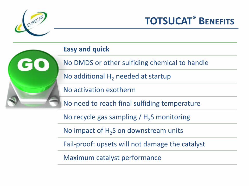
TOTSUCAT® BENEFITS
Easy and quick
No DMDS or other sulfiding chemical to handle
No additional H2 needed at startup
No activation exotherm
No need to reach final sulfiding temperature
No recycle gas sampling / H2S monitoring
No impact of H2S on downstream units
Fail-proof: upsets will not damage the catalyst
Maximum catalyst performance

TYPICAL TOTSUCAT® APPLICATIONS
• Downtime cost for in situ sulfiding often outweighs Totsucat cost.
• Totsucat with Amine passivation for Hydrocrackers saves precious startup time.
Critical Path Units
• Some units cannot achieve correct sulfiding temperature: in situ sulfided catalysts will not perform as designed.
Temperature Limited Units
• Reformers and Isom units contain precious metal catalysts that are sensitive to H2S contamination.
Before Sulfur Sensitive Units
• Some units are difficult to sulfide, as there is not enough H2
available at the time of startup.
Hydrogen Limited Units

Over 1200 Totsucat lots treated worldwide: 30 000 tons of catalyst
Hydrotreating
• CoMo, NiMo, NiCoMo
Selective Hydrogenation
• NiMo and CoMo
Pyrolysis Gasoline
• NiMo and CoMo
Hydrocracking
• NiMo and NiW
Lube / Wax Hydrofinishing
• NiMo and CoMo
• NiW
Other…
• Biofuels
• Contaminant traps
• …..
TOTSUCAT® COMMERCIAL EXPERIENCE

TOTSUCAT ® BRANDS
• Naphtha, Kero, FCC gasoline, Tail Gas, Lubes
TOTSUCAT – G
• (Ultra Low Sulfur) DieselTOTSUCAT – D
• Hydrocracking PretreatTOTSUCAT – N
• FCC PretreatTOTSUCAT – E
• HydrocrackingTOTSUCAT – HC
• Light Cycle Oil, Heavy Cycle Oil
• Coker and Visbreaker Naphtha / DieselTOTSUCAT – CFP

Temperature (°C)
400
300
200
100
10 20 30 hours +3 days
DMDS
Crackedfeed
Drying step
H2S breakthrough
Secondary Sulfiding
Stop DMDS
•SR Feed + DMDS at 80-150°C•Monitor H2S at outlet •Sulfide at 315-350°C•Sulfiding 3 days of SR feed
Initial Sulfiding
SR Feed
STARTUP WITH IN-SITU SULFIDING

Temperature (°C)
10 20 30 hours +3 days
Crackedfeed
DMDS
Drying step
H2S breakthrough
Secondary Sulfiding
Stop DMDS
•SR Feed + DMDS at 80-150°C•Monitor H2S at outlet •Sulfide at 315-350°C•Sulfiding 3 days of SR feed
Initial Sulfiding
SR Feed
SR Feed introduction at low T (80-150°C) Go to Start of Run Temp in only 6-10 h
Straight Runfeed
400
300
200
100
STARTUP WITH TOTSUCAT® G/D/E/N/HC
❑ Startup Liquid phase with SR Feed

ISSUE OF CRACKED FEED
Cracked feed (from Coker, FCC)contains (di)olefins and aromatics
Exposed to freshly sulfidedcatalyst, they polymerise
Gums deposits blockcatalyst pores and active
sites
Leading to a permanent loss in catalytic activity
❑ Catalyst manufacturers recommend a break-in period of at least 3 daysusing straight run feed. Solution: TOTSUCAT CFP

TOTSUCAT® CFP
• TOTSUCAT®-CFP mimics the 3 days break-in period
• Catalytic acidity is reduced no gums formation
• Can inject cracked feed immediately
• Proven in refineries: 60+ references
CFP = Cracked Feed Protection
• lost opportunity in order of ~500 k$
• plus associated logisitics cost.
Example case of 75 tons reactor treating 30% cracked feed

CASE STUDY
Recommendations from Catalyst Supplier:• « In a stressed unit, once the deactivation rate is high, it is nearly
impossible to reduce it. 2-3 % LCO added at the wrong moment is sufficient to double the deactivation rate.
• Therefore, it is critical to have a gentle and possibly somewhat lengthy startup to avoid premature activity loss.
• Run 3 days on virgin oil prior to the introduction of cracked stocks. Longer is better!
• Introduce cracked stocks in a slow, steady, controlled manner.• Do not push the unit in the first two weeks of operation! »
Instead, the refinery appliedTotsucat CFP

CASE STUDY - TOTSUCAT® CFP IN ULSD SERVICE AFTER 90 DAYS
ΔT = 35°F
Normalized to 0.2 wt% S
WA
BT
( F
°)
NORMALIZED TO 0.20 WT% S
Day on stream

CASE STUDY - TOTSUCAT® CFP IN ULSD SERVICE AFTER 320 DAYS
Normalized to 0.2 wt% S
❑Deactivation significantly lower with TOTSUCAT-CFP than with in situ!
ΔT = 35°F
Run length:50+ days

TOTSUCAT ® BRANDS
• Naphtha, Kero, FCC gasoline, Tail Gas, Lubes
TOTSUCAT – G
• (Ultra Low Sulfur) DieselTOTSUCAT – D
• Hydrocracking PretreatTOTSUCAT – N
• FCC PretreatTOTSUCAT – E
• HydrocrackingTOTSUCAT – HC AP
Acidity protection
• Light Cycle Oil, Heavy Cycle Oil
• Coker and Visbreaker Naphtha / DieselTOTSUCAT – CFP

HYDROCRACKING PROCESS: 2 STEPS OF REACTIONS

HDC: ISSUE OF START-UP
❑ Fresh vs steady state catalysts
▪ Zeolite catalyst contains very strong acidic sites: can crack hydrocarbons already around 250°C
▪ In steady state, the strongest acidic sites are essentially covered with N containing compounds (mainly ammonia) cracking temperatures are between 300 and 350°C.
❑ How to go from a fresh to a steady state catalysts?
1. Wait for a long time that N in the feed, transformed by HDN to NH3, slowly saturates the acidic sites
2. Inject during sulfiding procedure NH3 or another N containing compound
3. Use the TOTSUCAT HC-AP
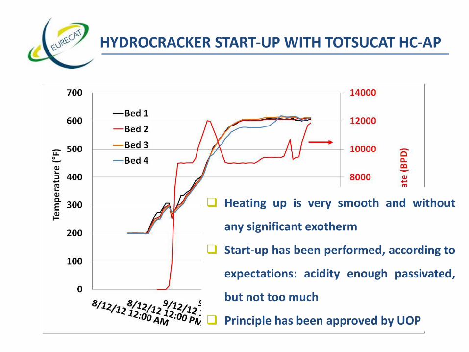
HYDROCRACKER START-UP WITH TOTSUCAT HC-AP
❑ Heating up is very smooth and without
any significant exotherm
❑ Start-up has been performed, according to
expectations: acidity enough passivated,
but not too much
❑ Principle has been approved by UOP

CONCLUSIONS
❑ Catalyst regeneration andreuse allows to drasticallyreduce expense:
❑ TOTSUCAT:
▪ Optimise catalystperformance
▪ Reduce unit downtime

Catalyst end-users: oil refiners & (petro)chemicals companies
Catalyst manufacturers
REGULAR CUSTOMERS
Group

Catalyst end-users: oil refiners & (petro)chemicals companies
Catalyst manufacturers
REGULAR CUSTOMERS
THANK YOU FOR YOU
ATTENTION!
Group