Embed Size (px)
Citation preview
Catalyst 6500 Series Switch and Cisco 7600 Series Router Wireless Services Module Installation and Verification Note
Product number: WS-SVC-WiSM-1-K9
This document provides installation procedures for the Catalyst 6500 Series Switch and Cisco 7600 Series Router Wireless Services Module (WiSM).
ContentsThis publication contains these sections:
• Front Panel Description, page 2
• System Requirements, page 3
• Safety Overview, page 4
• Required Tools, page 4
• Installing the WiSM, page 5
• Verifying the Installation, page 12
• Removing the WiSM, page 13
• Regulatory Standards Compliance, page 14
• Related Documentation, page 14
• Obtaining Documentation and Submitting a Service Request, page 14
Corporate Headquarters:
© 2005–2006 Cisco Systems, Inc. All rights reserved.
Cisco Systems, Inc., 170 West Tasman Drive, San Jose, CA 95134-1706 USA
Front Panel Description
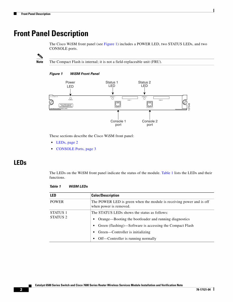
Front Panel DescriptionThe Cisco WiSM front panel (see Figure 1) includes a POWER LED, two STATUS LEDs, and two CONSOLE ports.
Note The Compact Flash is internal; it is not a field-replaceable unit (FRU).
Figure 1 WiSM Front Panel
These sections describe the Cisco WiSM front panel:
• LEDs, page 2
• CONSOLE Ports, page 3
LEDsThe LEDs on the WiSM front panel indicate the status of the module. Table 1 lists the LEDs and their functions.
POWER
STATUS 1
CONSOLE 1 CONSOLE 2
DISK 1
STATUS 2
DISK 2
PowerLED
Status 1LED
Status 2LED
Console 1port
Console 2port
1375
48Table 1 WiSM LEDs
LED Color/Description
POWER The POWER LED is green when the module is receiving power and is off when power is removed.
STATUS 1STATUS 2
The STATUS LEDs shows the status as follows:
• Orange—Booting the bootloader and running diagnostics
• Green (flashing)—Software is accessing the Compact Flash
• Green—Controller is initializing
• Off—Controller is running normally
2Catalyst 6500 Series Switch and Cisco 7600 Series Router Wireless Services Module Installation and Verification Note
78-17121-04

System Requirements
CONSOLE PortsThe CONSOLE ports allow you to access each controller either locally (with a console terminal) or remotely (with a modem). The CONSOLE ports are EIA/TIA-232 asynchronous, serial connections with hardware flow control and RJ-45 connectors.
System RequirementsThese sections describe the hardware and software requirements:
• Hardware Components, page 3
• Power Requirements, page 3
• Software Requirements, page 4
Hardware Components
Note The The Catalyst 6500 series or Cisco 7609 or 7613 chassis can support up to five Cisco WiSMs without any other service module installed. If one or more service modules are installed, the chassis can support up to four service modules (WiSMs included).
The Catalyst 6500 series or Cisco 7609 or 7613 chassis in which the Cisco WiSM is installed requires a Supervisor 720 module. The supported slots for the Cisco WiSM are listed in Table 2.
Power RequirementsThe Cisco WiSM module requires 164W for operation. Make sure that your chassis can provide this power.
Note All Catalyst 6500 chassis (except the Catalyst 6503) require the fan tray 2 module, which requires the 2500W power supply for proper operation. For planning purposes, be aware that the 2500W power supply requires a 20A input power circuit with a NEMA plug.
Table 2 Supported Slots for the Cisco WiSM
Slot Catalyst 6503 Catalyst 6504 Catalyst 6506Catalyst 6509Cisco 7609
Catalyst 6513Cisco 7613
1–3 x x x x –
4 – x x x –
5–6 – – x x –
7–8 – – – x –
9 – – – x x
10–13 – – – – x
3Catalyst 6500 Series Switch and Cisco 7600 Series Router Wireless Services Module Installation and Verification Note
78-17121-04
Safety Overview
You can use the show power command to view power details for your installation, including the system power available and power statistics for installed power supplies and cards.
Software RequirementsBefore you install the WiSM into the chassis, make sure that the module and the chassis meet the software requirements. Refer to the Release Notes for Cisco Wireless LAN Controllers and Lightweight Access Points at this URL:
http://www.cisco.com/en/US/products/ps6366/index.html
Safety Overview Safety warnings appear throughout this publication in procedures that, if performed incorrectly, may harm you. A warning symbol precedes each warning statement.
Warning Only trained and qualified personnel should be allowed to install, replace, or service this equipment. Statement 1030
Warning Blank faceplates and cover panels serve three important functions: they prevent exposure to hazardous voltages and currents inside the chassis; they contain electromagnetic interference (EMI) that might disrupt other equipment; and they direct the flow of cooling air through the chassis. Do not operate the system unless all cards, faceplates, front covers, and rear covers are in place. Statement 1029
Required ToolsThese tools are required to install the WiSM in the Catalyst 6500 series switches or the Cisco 7600 series routers:
• Number 2 Phillips screwdriver
• Antistatic mat or antistatic foam
Warning IMPORTANT SAFETY INSTRUCTIONS
This warning symbol means danger. You are in a situation that could cause bodily injury. Before you work on any equipment, be aware of the hazards involved with electrical circuitry and be familiar with standard practices for preventing accidents. Use the statement number provided at the end of each warning to locate its translation in the translated safety warnings that accompanied this device. Statement 1071
SAVE THESE INSTRUCTIONS
4Catalyst 6500 Series Switch and Cisco 7600 Series Router Wireless Services Module Installation and Verification Note
78-17121-04

Installing the WiSM
• Your own electrostatic discharge (ESD) grounding strap or the disposable ESD strap included with the system
Warning Blank faceplates and cover panels serve three important functions: they prevent exposure to hazardous voltages and currents inside the chassis; they contain electromagnetic interference (EMI) that might disrupt other equipment; and they direct the flow of cooling air through the chassis. Do not operate the system unless all cards, faceplates, front covers, and rear covers are in place. Statement 1029
Installing the WiSMThis section describes how to install the WiSM in the Catalyst 6500 series switches or the Cisco 7600 series routers.
Caution To prevent ESD damage, handle modules by the carrier edges only and wear grounding wrist straps.
Note Specific combinations of supervisor engines and modules may not be supported in your chassis. Refer to the release notes of the software version running on your system for specific information on modules and supervisor engine combinations that are not supported.
To install the WiSM in the chassis, follow these steps:
Step 1 Choose a slot for the WiSM.
Step 2 Verify that there is enough clearance to accommodate any interface equipment that you will connect directly to the WiSM ports. If possible, place modules between empty slots that contain only module filler plates.
Step 3 Verify that the captive installation screws are tightened on all modules installed in the chassis. This assures that the EMI gaskets on all modules are fully compressed in order to maximize the opening space for the new module or the replacement module.
Note If the captive installation screws are loose, the EMI gaskets on the installed modules will push adjacent modules toward the open slot, reducing the opening size and making it difficult to install the replacement module.
Step 4 Remove the module filler plate by removing the two Phillips pan-head screws from the filler plate. To remove a module, see the “Removing the WiSM” section on page 13.
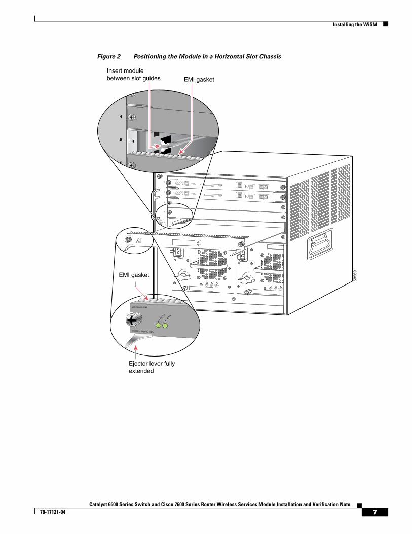
Step 5 Fully open both ejector levers on the WiSM. (See Figure 2.)
Step 6 Depending on the orientation of the slots in the chassis (horizontal or vertical), perform one of the following two sets of substeps.
5Catalyst 6500 Series Switch and Cisco 7600 Series Router Wireless Services Module Installation and Verification Note
78-17121-04
Installing the WiSM
Horizontal slots
a. Position the WiSM in the slot. (See Figure 2.) Make sure that you align the sides of the module carrier with the slot guides on each side of the slot.
b. Carefully slide the WiSM into the slot until the EMI gasket along the top edge of the module makes contact with the module in the slot above it and both ejector levers have closed to approximately 45 degrees with respect to the module faceplate. (See Figure 3.)
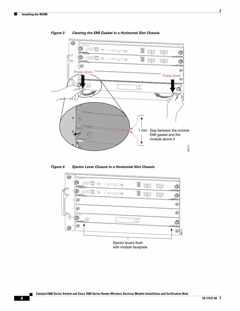
c. Using the thumb and forefinger of each hand, grasp the two ejector levers and press down to create a small (0.040 inch [1 mm]) gap between the module’s EMI gasket and the module above it. (See Figure 3.)
Caution Do not press down too hard on the levers. They will bend and be damaged.
d. While pressing down, simultaneously close the left and right ejector levers to fully seat the supervisor engine or module in the backplane connector. The ejector levers are fully closed when they are flush with the module faceplate. (See Figure 4.)
Note Failure to fully seat the module in the backplane connector can result in error messages.
e. Tighten the two captive installation screws on the WiSM.
Note Make sure the ejector levers are fully closed before tightening the captive installation screws.
f. Verify that the WiSM STATUS LED is lit. Check the STATUS LED periodically. If the STATUS LED changes from orange to green, the WiSM has successfully completed the boot process and is now online. If the STATUS LED remains orange or turns red, the WiSM has not successfully completed the boot process and may have encountered an error.
6Catalyst 6500 Series Switch and Cisco 7600 Series Router Wireless Services Module Installation and Verification Note
78-17121-04
Installing the WiSM
Figure 2 Positioning the Module in a Horizontal Slot Chassis
5856
9
INPUTOK
FANOK
OUTPUTFAIL
o
INPUTOK
FANOK
OUTPUTFAIL
o
1
2
3
FANSTATUS
4
5
6
SUPERVISOR2
WS-X6K-SUP2-2GE
STATUS
SYSTEM
CONSOLE
PWR M
GMT
RESET
CONSOLE
CONSOLEPORTMODE
PCMCIA EJECT
PORT 1 PORT 2
Switch Load 100%
1%
24 PORT 100FX
WS-X6224
SELECT
NEXT
EMI gasket
EMI gasket
Insert module between slot guides
Ejector lever fully extended
STATUS
ACTIVE
4
3
55
4
6 6
SWITCH FABRIC MDL
WS-C6500-SFM
STATUS
ACTIVE
SUPERVISOR2
WS-X6K-SUP2-2GE
STATUS
SYSTEM
CONSOLE
PWR M
GMT
RESET
CONSOLE
CONSOLEPORTMODE
PCMCIA EJECT
PORT 1 PORT 2
Switch Load 100%
1%
7Catalyst 6500 Series Switch and Cisco 7600 Series Router Wireless Services Module Installation and Verification Note
78-17121-04
Installing the WiSM
Figure 3 Clearing the EMI Gasket in a Horizontal Slot Chassis
Figure 4 Ejector Lever Closure in a Horizontal Slot Chassis
1
2
3
FANSTATUS
4
5
6
SUPERVISOR2
WS-X6K-SUP2-2GE
STATUS
SYSTEM
CONSOLE
PWR M
GMT
RESET
CONSOLE
CONSOLEPORTMODE
PCMCIA EJECT
PORT 1 PORT 2
Switch Load 100%
1%
LINK
LINK
SUPERVISOR2
WS-X6K-SUP2-2GE
STATUS
SYSTEM
CONSOLE
PWR M
GMT
RESET
CONSOLE
CONSOLEPORTMODE
PCMCIA EJECT
PORT 1 PORT 2
Switch Load 100%
1%
LINK
LINK
1 mm
24 PORT 100FX
WS-X6224
STATUS
ACTIVE
SELECT
NEXT
4
3
55
4
6 6
SWITCH FABIRD MDL
WS-C6500-SFM
STATUS
ACTIVE
Gap between the moduleEMI gasket and the module above it
Press downPress down
5857
0
1
2
3
FANSTATUS
4
5
6
SUPERVISOR2
WS-X6K-SUP2-2GE
STATUS
SYSTEM
CONSOLE
PWR M
GMT
RESET
CONSOLE
CONSOLEPORTMODE
PCMCIA EJECT
PORT 1 PORT 2
Switch Load 100%
1%
LINK
LINK
SUPERVISOR2
WS-X6K-SUP2-2GE
STATUS
SYSTEM
CONSOLE
PWR M
GMT
RESET
CONSOLE
CONSOLEPORTMODE
PCMCIA EJECT
PORT 1 PORT 2
Switch Load 100%
1%
LINK
LINK
SWITCH FABRIC MDL
WS-C6500-SFM
STATUS
ACTIVE
SELECT
NEXT
5857
1
Ejector levers flushwith module faceplate
8Catalyst 6500 Series Switch and Cisco 7600 Series Router Wireless Services Module Installation and Verification Note
78-17121-04
Installing the WiSM
Vertical slots
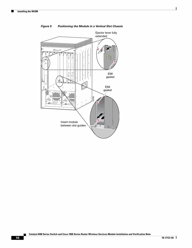
a. Position the supervisor engine or switching module in the slot. (See Figure 5.) Make sure that you align the sides of the switching-module carrier with the slot guides on the top and bottom of the slot.
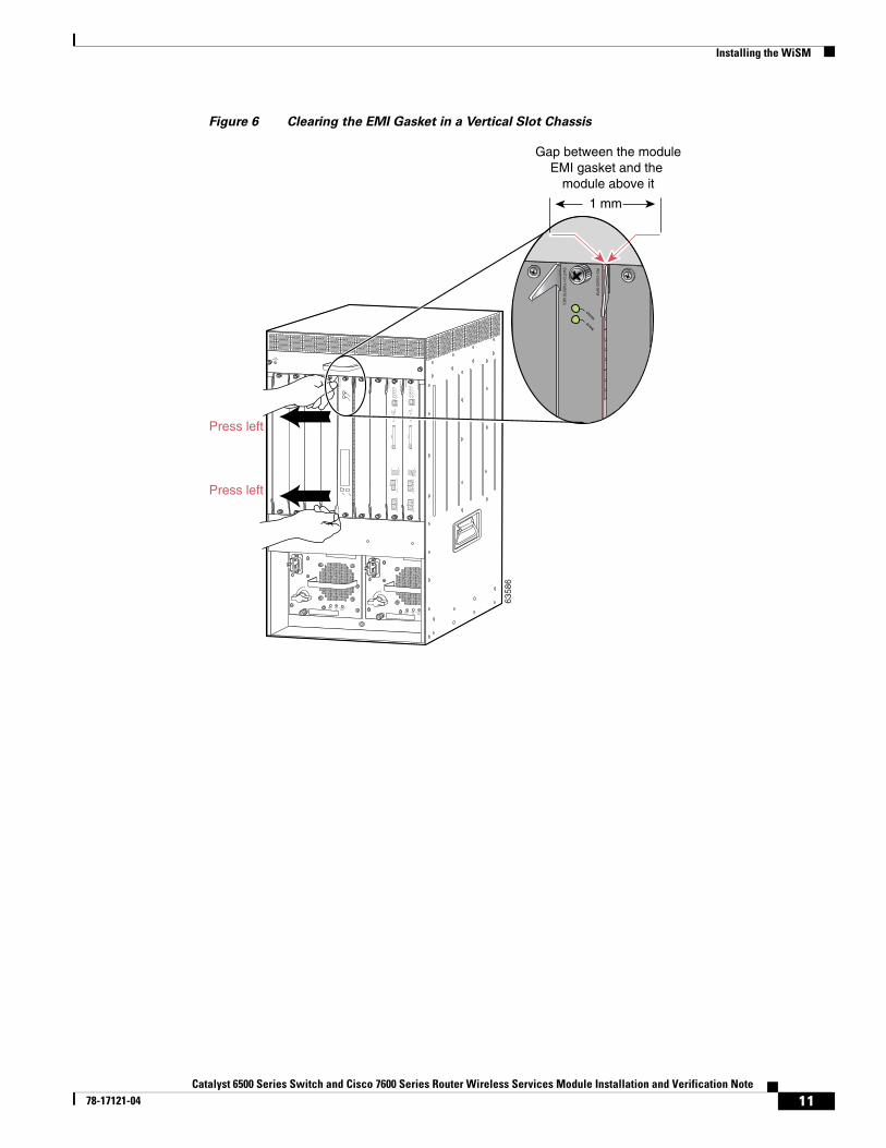
b. Carefully slide the WiSM into the slot until the EMI gasket along the right edge of the module makes contact with the module in the slot adjacent to it and both ejector levers have closed to approximately 45 degrees with respect to the module faceplate. (See Figure 6.)
c. Using the thumb and forefinger of each hand, grasp the two ejector levers and exert a slight pressure to the left, deflecting the module approximately 0.04 inches (1 mm) to create a small gap between the module’s EMI gasket and the module adjacent to it. (See Figure 6.)
Caution Do not exert too much pressure on the ejector levers. They will bend and be damaged.
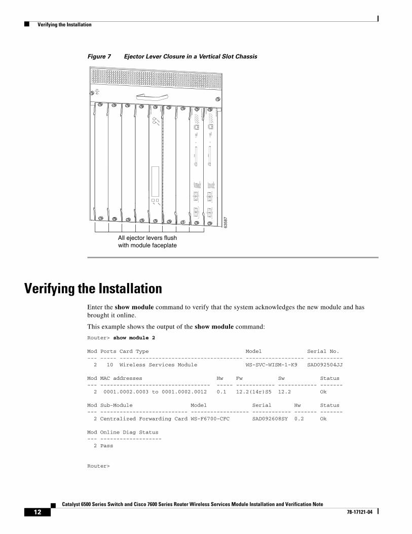
d. While pressing on the ejector levers, simultaneously close them to fully seat the WiSM in the backplane connector. The ejector levers are fully closed when they are flush with the module faceplate. (See Figure 7.)
e. Tighten the two captive installation screws on the module.
Note Make sure that the ejector levers are fully closed before tightening the captive installation screws.
f. Verify that the WiSM STATUS LED is lit. Check the STATUS LED periodically. If the STATUS LED changes from orange to green, the WiSM has successfully completed the boot process and is now online. If the STATUS LED remains orange or turns red, the WiSM has not successfully completed the boot process and may have encountered an error.
9Catalyst 6500 Series Switch and Cisco 7600 Series Router Wireless Services Module Installation and Verification Note
78-17121-04
Installing the WiSM
Figure 5 Positioning the Module in a Vertical Slot Chassis
INPUTOK
FANOK
OUTPUTFAIL
o
INPUTOK
FANOK
OUTPUTFAIL
o
FANSTATUS
Ejector lever fully extended
SU
PE
RV
ISO
R2
WS
-X6K
- SU
P2- 2
GE
STATUSSYSTEMCONSO
LEPWR M
GM
T
RESET
CO
NS
OL
E
CO
NS
OL
E
PO
RT
MO
DE
PC
MC
IAE
JEC
T
PO
RT
1P
OR
T 2
Sw
itch L
oa
d
10
0%
1%
SU
PE
RV
ISO
R2
WS
-X6K
-SU
P2-2G
E
STATUSSYSTEMCONSO
LEPWR M
GM
T
RESET
CO
NS
OLE
CO
NS
OLE
PO
RT
MO
DE
PC
MC
IAE
JEC
T
PO
RT
1P
OR
T 2
Sw
itch Load 100%
1%
SW
ITCH
FAB
RIC
MD
L
WS
-C6500-S
FM
STATUS
ACTIVE
4 3
6
SELECT
NEXT
24 PO
RT 100FX
WS
-X6224
STATUS
ACTIVE
EMIgasket
EMIgasket
6358
5
Insert module between slot guides
10Catalyst 6500 Series Switch and Cisco 7600 Series Router Wireless Services Module Installation and Verification Note
78-17121-04
Installing the WiSM
Figure 6 Clearing the EMI Gasket in a Vertical Slot Chassis
INPUTOK
FANOK
OUTPUTFAIL
o
INPUTOK
FANOK
OUTPUTFAIL
o
FANSTATUS
SELECT
NEXT
24 PO
RT
100FX
WS
-X6224
STATUS
ACTIVE
SU
PE
RV
ISO
R2
WS
- X6
K- S
UP
2- 2
GE
STATUSSYSTEMCONSO
LEPWR M
GM
T
RESET
CO
NS
OL
E
CO
NS
OL
E
PO
RT
MO
DE
PC
MC
IAE
JEC
T
PO
RT
1P
OR
T 2
Sw
itch L
oa
d
10
0%
1%
SU
PE
RV
ISO
R2
WS
-X6K
-SU
P2-2G
E
STATUSSYSTEMCONSO
LEPWR M
GM
T
RESET
CO
NS
OLE
CO
NS
OLE
PO
RT
MO
DE
PC
MC
IAE
JEC
T
PO
RT
1P
OR
T 2
Sw
itch Load 100%
1%
6358
6
Gap between the moduleEMI gasket and the
module above it
SW
ITCH
FAB
IRD
MD
L
WS
-C6500-S
FM
STATUS
ACTIVE
1 mm
Press left
Press left
11Catalyst 6500 Series Switch and Cisco 7600 Series Router Wireless Services Module Installation and Verification Note
78-17121-04
Verifying the Installation
Figure 7 Ejector Lever Closure in a Vertical Slot Chassis
Verifying the InstallationEnter the show module command to verify that the system acknowledges the new module and has brought it online.
This example shows the output of the show module command:
Router> show module 2
Mod Ports Card Type Model Serial No.--- ----- -------------------------------------- ------------------ -----------
2 10 Wireless Services Module WS-SVC-WISM-1-K9 SAD092504JJ
Mod MAC addresses Hw Fw Sw Status--- ---------------------------------- ----- ------------ ------------ -------
2 0001.0002.0003 to 0001.0002.0012 0.1 12.2(14r)S5 12.2 Ok
Mod Sub-Module Model Serial Hw Status--- --------------------------- ------------------ ------------ ------- -------
2 Centralized Forwarding Card WS-F6700-CFC SAD092608SY 0.2 Ok
Mod Online Diag Status--- -------------------
2 Pass
Router>
FANSTATUS
SELECT
NEXT
24 PO
RT
100FX
WS
-X6224
STATUS
ACTIVE
SU
PE
RV
ISO
R2
WS
-X6K
-SU
P2-2
GE
STATUSSYSTEMCONSO
LEPWR M
GM
T
RESET
CO
NS
OL
E
CO
NS
OL
EP
OR
TM
OD
E
PC
MC
IAE
JEC
T
PO
RT
1P
OR
T 2
Sw
itch L
oa
d
10
0%
1%
SU
PE
RV
ISO
R2
WS
-X6K
-SU
P2-2G
E
STATUSSYSTEMCONSO
LEPWR M
GM
T
RESET
CO
NS
OLE
CO
NS
OLE
PO
RT
MO
DE
PC
MC
IAE
JEC
T
PO
RT
1P
OR
T 2
Sw
itch Load 100%
1%
6358
7
All ejector levers flushwith module faceplate
12Catalyst 6500 Series Switch and Cisco 7600 Series Router Wireless Services Module Installation and Verification Note
78-17121-04
Removing the WiSM
Removing the WiSMThis section describes how to remove an existing WiSM from a chassis slot.
Caution Do not remove the Cisco WiSM from the chassis until the module has shut down completely and the STATUS LED is orange or off. You can damage the module if you remove it from the chassis before it completely shuts down.
Caution During this procedure, wear grounding wrist straps to avoid ESD damage to the card.
To remove a WiSM from the chassis, follow these steps:
Step 1 In configuration mode from the router prompt, enter the no power enable module mod command.
Note Shutdown may require several minutes.
Step 2 Verify that the WiSM is down. Do not remove the module from the switch until the STATUS LEDs are off or orange.
Step 3 Use a screwdriver to loosen the captive installation screws at the left and right sides of the module.
Step 4 Grasp the left and right ejector levers. Simultaneously, pull the left lever to the left and the right lever to the right to release the module from the backplane connector.
Step 5 As you pull the module out of the slot, place one hand under the carrier to support it. Avoid touching the module itself.
Step 6 Carefully pull the module straight out of the slot, keeping one hand under the carrier to guide it. Keep the module at a 90-degree orientation to the backplane (horizontal to the floor).
Step 7 Place the removed module on an antistatic mat or antistatic foam.
Warning Blank faceplates and cover panels serve three important functions: they prevent exposure to hazardous voltages and currents inside the chassis; they contain electromagnetic interference (EMI) that might disrupt other equipment; and they direct the flow of cooling air through the chassis. Do not operate the system unless all cards, faceplates, front covers, and rear covers are in place. Statement 1029
Step 8 If the slot is to remain empty, install a module filler plate to keep dust out of the chassis and to maintain proper airflow through the module compartment.
Configuring the WiSMFor information on configuring the WiSM, refer to the Cisco Wireless LAN Controller Configuration Guide and the Cisco Wireless LAN Controller Command Reference at this URL: http://www.cisco.com/en/US/products/ps6366/index.html
13Catalyst 6500 Series Switch and Cisco 7600 Series Router Wireless Services Module Installation and Verification Note
78-17121-04
Regulatory Standards Compliance
Regulatory Standards ComplianceCatalyst 6500 series switching modules comply with the regulatory standards listed in the Regulatory Compliance and Safety Information for the Catalyst 6500 Series Switches publication. Cisco 7600 series routers comply with the regulatory standards listed in the Regulatory Compliance and Safety Information for the Cisco 7600 Series Router publication.
Related DocumentationFor more detailed installation and configuration information, refer to these publications:
• Regulatory Compliance and Safety Information for the Catalyst 6500 Series Switches
• Regulatory Compliance and Safety Information for the Cisco 7600 Series Router
• Catalyst 6500 Series Switch Module Installation Guide
• Catalyst 6500 Series Switch Cisco IOS Software Configuration Guide
• Catalyst 6500 Series Switch Software Configuration Guide
• Catalyst 6500 Series Switch Command Reference
• Cisco 7600 Series Router Installation Guide
• Cisco 7600 Series Router Software Configuration Guide
• Cisco 7600 Series Router Command Reference
• Cisco Wireless LAN Controller Configuration Guide
• Cisco Wireless LAN Controller Command Reference
• Release Notes for Cisco Wireless LAN Controllers and Lightweight Access Points
Obtaining Documentation and Submitting a Service RequestFor information on obtaining documentation, submitting a service request, and gathering additional information, see the monthly What’s New in Cisco Product Documentation, which also lists all new and revised Cisco technical documentation, at:
http://www.cisco.com/en/US/docs/general/whatsnew/whatsnew.html
Subscribe to the What’s New in Cisco Product Documentation as an RSS feed and set content to be delivered directly to your desktop using a reader application. The RSS feeds are a free service. Cisco currently supports RSS Version 2.0.
14Catalyst 6500 Series Switch and Cisco 7600 Series Router Wireless Services Module Installation and Verification Note
78-17121-04
Related Documentation
This document is to be used in conjunction with the documents listed in the “Related Documentation” section.
Any Internet Protocol (IP) addresses used in this document are not intended to be actual addresses. Any examples, command display output, and figures included in the document are shown for illustrative purposes only. Any use of actual IP addresses in illustrative content is unintentional and coincidental.
© 2005–2006 Cisco Systems, Inc. All rights reserved.
Printed in the USA on recycled paper containing 10% postconsumer waste.
CCVP, the Cisco logo, and Welcome to the Human Network are trademarks of Cisco Systems, Inc.; Changing the Way We Work, Live, Play, and Learn isa service mark of Cisco Systems, Inc.; and Access Registrar, Aironet, Catalyst, CCDA, CCDP, CCIE, CCIP, CCNA, CCNP, CCSP, Cisco, the CiscoCertified Internetwork Expert logo, Cisco IOS, Cisco Press, Cisco Systems, Cisco Systems Capital, the Cisco Systems logo, Cisco Unity,Enterprise/Solver, EtherChannel, EtherFast, EtherSwitch, Fast Step, Follow Me Browsing, FormShare, GigaDrive, HomeLink, Internet Quotient, IOS,iPhone, IP/TV, iQ Expertise, the iQ logo, iQ Net Readiness Scorecard, iQuick Study, LightStream, Linksys, MeetingPlace, MGX, Networkers,Networking Academy, Network Registrar, PIX, ProConnect, ScriptShare, SMARTnet, StackWise, The Fastest Way to Increase Your Internet Quotient,and TransPath are registered trademarks of Cisco Systems, Inc. and/or its affiliates in the United States and certain other countries.
All other trademarks mentioned in this document or Website are the property of their respective owners. The use of the word partner does not imply apartnership relationship between Cisco and any other company. (0711R)
15Catalyst 6500 Series Switch and Cisco 7600 Series Router Wireless Services Module Installation and Verification Note
78-17121-04

Related Documentation
16Catalyst 6500 Series Switch and Cisco 7600 Series Router Wireless Services Module Installation and Verification Note
78-17121-04