Embed Size (px)
Citation preview

Catalyst 4500-X Series Switch Installation Note
Revised: August 29, 2012
This document covers the installation process for the Catalyst 4500-X series switch chassis.
ContentsThis installation note contains the following sections:
• Overview, page 2
• Safety, page 9
• Site Requirements, page 16
• Rack Mounting Kits, page 28
• Installing the Chassis in an Equipment Rack Using the Standard Rack-Mount Kit, page 28
• Optional Rack-Mount Kit Installation Instructions, page 33
• Attaching System Ground, page 41
• Installing the Interface Cables, page 42
• Attaching the AC-Input Power Supply Power Cord, page 45
• Attaching the DC-Input Power Supply Power Cable, page 46
• Monitoring the LEDs, page 46
• Related Documentation, page 50
• Obtaining Documentation and Submitting a Service Request, page 50
Product Numbers: WS-C4500X-16SFP+ WS-C4500X-F-16SFP+ WS-C4500X-24X-ES
WS-C4500X-32SFP+ WS-C4500X-F-32SFP+ WS-C4500X-40X-ES
Americas Headquarters:Cisco Systems, Inc., 170 West Tasman Drive, San Jose, CA 95134-1706 USA
Overview
OverviewThe Catalyst 4500-X series switch is a 1RU unit that provides either 16 or 32 10GBASE-X (SFP+) or 1GBASE-X (SFP) ports. An additional 8 ports of 1000BASE-X (SFP) or 10GBASE-X (SFP+) are available in a removable Ethernet uplink module that mounts in a bay on the front of the switch chassis. The six models of the Catalyst 4500-X series switch are listed in Table 1.
Note Power supplies, either AC-input or DC-input, are not included as part of the basic chassis configuration product numbers listed in Table 1. The power supplies are ordered separately. See the product data sheet for further information.
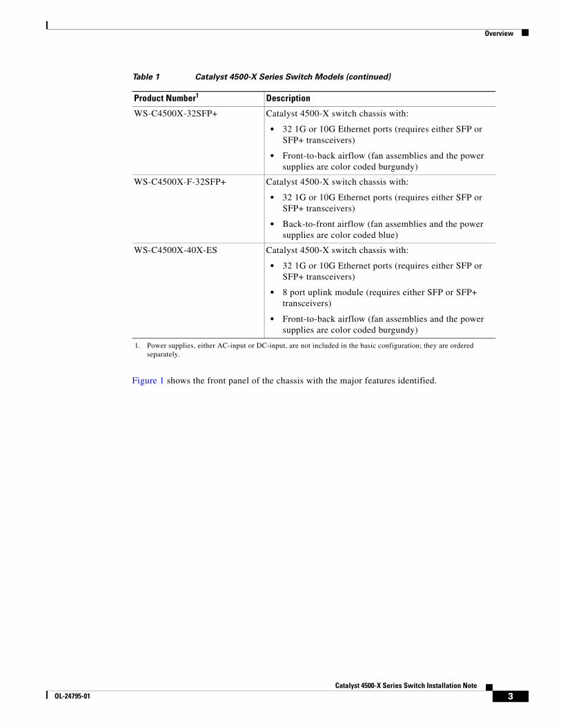
Table 1 Catalyst 4500-X Series Switch Models
Product Number1 Description
WS-C4500X-16SFP+ Catalyst 4500-X switch chassis with:
• 16 1G or 10G Ethernet ports (requires either SFP or SFP+ transceivers)
• Front-to-back airflow (fan assemblies and the power supplies are color coded burgundy)
WS-C4500X-F-16SFP+ Catalyst 4500-X switch chassis with:
• 16 1G or 10G Ethernet ports (requires either SFP or SFP+ transceivers)
• Back-to-front airflow (fan assemblies and the power supplies are color coded blue)
WS-C4500X-24X-ES Catalyst 4500-X switch chassis with:
• 16 1G or 10G Ethernet ports (requires either SFP or SFP+ transceivers)
• 8 port uplink module (requires either SFP or SFP+ transceivers)
• Front-to-back airflow (fan assemblies and the power supplies are color coded burgundy)
2Catalyst 4500-X Series Switch Installation Note
OL-24795-01
Overview
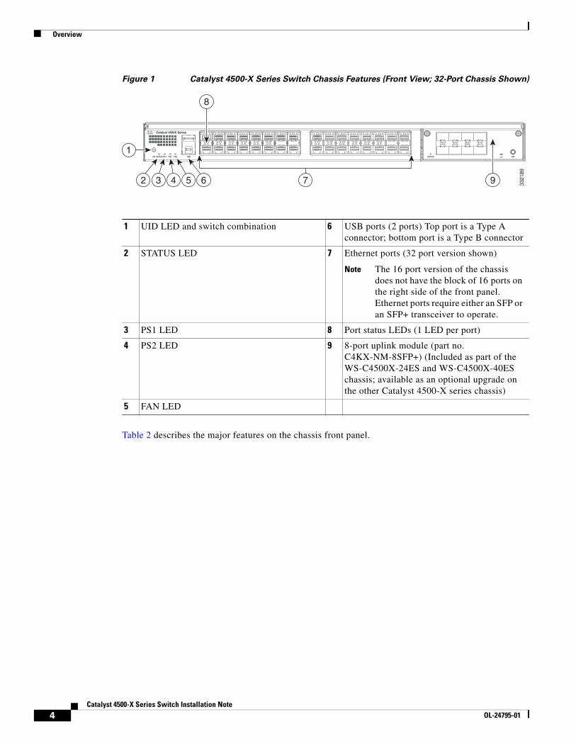
Figure 1 shows the front panel of the chassis with the major features identified.
WS-C4500X-32SFP+ Catalyst 4500-X switch chassis with:
• 32 1G or 10G Ethernet ports (requires either SFP or SFP+ transceivers)
• Front-to-back airflow (fan assemblies and the power supplies are color coded burgundy)
WS-C4500X-F-32SFP+ Catalyst 4500-X switch chassis with:
• 32 1G or 10G Ethernet ports (requires either SFP or SFP+ transceivers)
• Back-to-front airflow (fan assemblies and the power supplies are color coded blue)
WS-C4500X-40X-ES Catalyst 4500-X switch chassis with:
• 32 1G or 10G Ethernet ports (requires either SFP or SFP+ transceivers)
• 8 port uplink module (requires either SFP or SFP+ transceivers)
• Front-to-back airflow (fan assemblies and the power supplies are color coded burgundy)
1. Power supplies, either AC-input or DC-input, are not included in the basic configuration; they are ordered separately.
Table 1 Catalyst 4500-X Series Switch Models (continued)
Product Number1 Description
3Catalyst 4500-X Series Switch Installation Note
OL-24795-01
Overview
Figure 1 Catalyst 4500-X Series Switch Chassis Features (Front View; 32-Port Chassis Shown)
Table 2 describes the major features on the chassis front panel.
1 UID LED and switch combination 6 USB ports (2 ports) Top port is a Type A connector; bottom port is a Type B connector
2 STATUS LED 7 Ethernet ports (32 port version shown)
Note The 16 port version of the chassis does not have the block of 16 ports on the right side of the front panel. Ethernet ports require either an SFP or an SFP+ transceiver to operate.
3 PS1 LED 8 Port status LEDs (1 LED per port)
4 PS2 LED 9 8-port uplink module (part no. C4KX-NM-8SFP+) (Included as part of the WS-C4500X-24ES and WS-C4500X-40ES chassis; available as an optional upgrade on the other Catalyst 4500-X series chassis)
5 FAN LED
Catalyst 4500X Series
STATUS STATUSOIR
UID PS1 PS2 FAN USB OIR
3321
89
1
8
972 3 4 5 6
4Catalyst 4500-X Series Switch Installation Note
OL-24795-01
Overview
Table 2 Catalyst 4500-X Series Switch Front Panel Feature Descriptions
Feature Description
UID switch and LED Universal ID (UID) beacon. A combination push button switch and LED indicator. The blue LED can be turned on either by pressing the UID switch on the front panel or through software. The main purpose of the beacon LED is to enable identification from a remote location during configuration or troubleshooting. The ability to turn on/off the LED by pressing a switch allows you to walk to the other side of a fully populated rack and identify the switch (there is a corresponding blue beacon LED on the chassis’s back panel. Pressing the blue beacon LED switch toggles the beacon LED on and off.
STATUS LED Multi-color LED that provides status of the system.
Green—The system is up and running.
Red—System fault is detected.
Amber—Solid (not flashing); either a minor alarm was detected in the system or the system is booting and awaiting Power-on self-test (POST).
Amber—Flashing; POST boot up is occurring.
Off—System is not powered up.
PS1/PS2 LED LED that provides the operational status of the chassis power supplies.
• Green—AC-input or DC-input power is OK.
• Red—Power supply fault detected. (Can be either voltage or power supply fan issues.)
Note Individual power supply status is also available through two LEDs mounted on each power supply at the back of the chassis.
FAN LED LED that provides operational status of the fan assemblies.
• Green—Fan assemblies OK.
• Amber—One fan assembly failure has been detected (warning).
• Red—Two or more fan assembly failures have been detected (critical failure).
Note Individual fan assembly status is available through an LED mounted on each fan assembly at the back of the chassis.
USB ports USB Type A interface (top connector) provides access to an external USB FLASH device (also known as a thumb drive or a USB key). The interface supports the 4-GB Cisco USB flash drive (Cisco part no. USB-X45-4GB-E). The Cisco IOS software provides standard file system access to the flash device: read, write, erase, and copy, as well as formatting of the flash device with a FAT file system. You can boot the switch from the USB drive
Note Currently, there is no support for the USB B-port (bottom connector).
Ethernet ports Either 16 or 32 1GBASE-X or 10GBASE-X ports. Each port requires either an SFP or SFP+ transceiver be installed to operate.
5Catalyst 4500-X Series Switch Installation Note
OL-24795-01
Overview
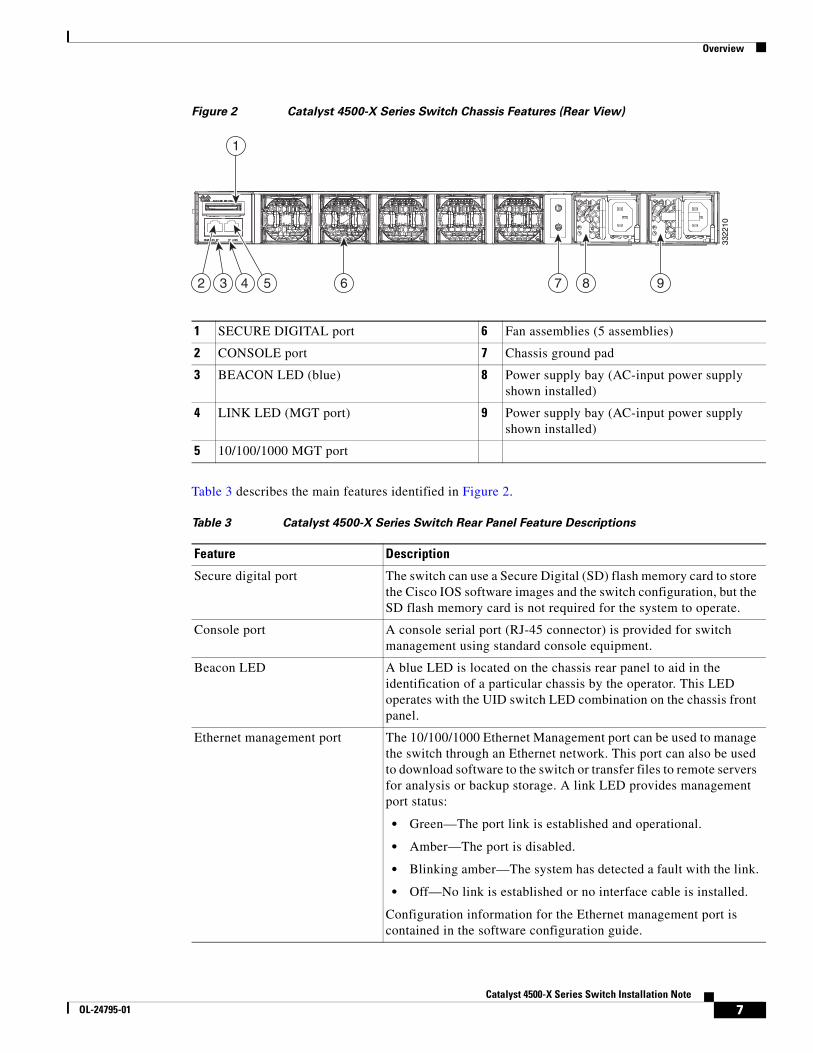
Figure 2 shows the rear of the switch chassis and identifies the major features.
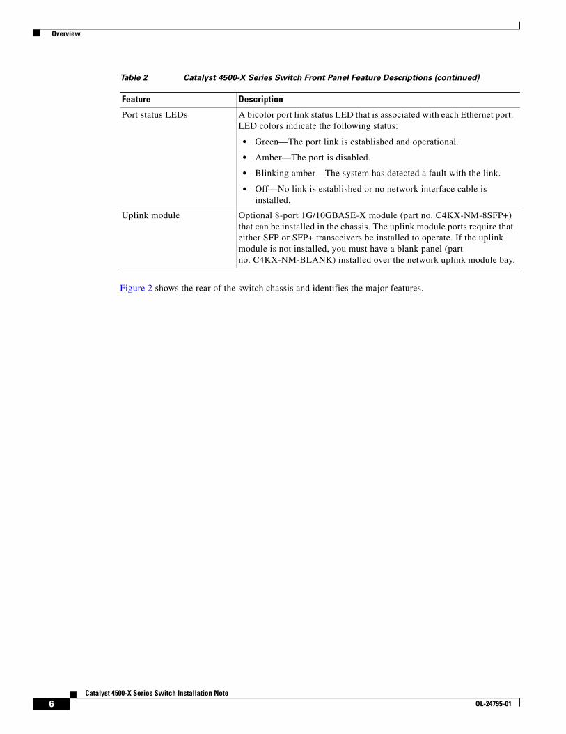
Port status LEDs A bicolor port link status LED that is associated with each Ethernet port. LED colors indicate the following status:
• Green—The port link is established and operational.
• Amber—The port is disabled.
• Blinking amber—The system has detected a fault with the link.
• Off—No link is established or no network interface cable is installed.
Uplink module Optional 8-port 1G/10GBASE-X module (part no. C4KX-NM-8SFP+) that can be installed in the chassis. The uplink module ports require that either SFP or SFP+ transceivers be installed to operate. If the uplink module is not installed, you must have a blank panel (part no. C4KX-NM-BLANK) installed over the network uplink module bay.
Table 2 Catalyst 4500-X Series Switch Front Panel Feature Descriptions (continued)
Feature Description
6Catalyst 4500-X Series Switch Installation Note
OL-24795-01
Overview
Figure 2 Catalyst 4500-X Series Switch Chassis Features (Rear View)
Table 3 describes the main features identified in Figure 2.
1 SECURE DIGITAL port 6 Fan assemblies (5 assemblies)
2 CONSOLE port 7 Chassis ground pad
3 BEACON LED (blue) 8 Power supply bay (AC-input power supply shown installed)
4 LINK LED (MGT port) 9 Power supply bay (AC-input power supply shown installed)
5 10/100/1000 MGT port
6 7 8 93 4 52
1
3322
10
Table 3 Catalyst 4500-X Series Switch Rear Panel Feature Descriptions
Feature Description
Secure digital port The switch can use a Secure Digital (SD) flash memory card to store the Cisco IOS software images and the switch configuration, but the SD flash memory card is not required for the system to operate.
Console port A console serial port (RJ-45 connector) is provided for switch management using standard console equipment.
Beacon LED A blue LED is located on the chassis rear panel to aid in the identification of a particular chassis by the operator. This LED operates with the UID switch LED combination on the chassis front panel.
Ethernet management port The 10/100/1000 Ethernet Management port can be used to manage the switch through an Ethernet network. This port can also be used to download software to the switch or transfer files to remote servers for analysis or backup storage. A link LED provides management port status:
• Green—The port link is established and operational.
• Amber—The port is disabled.
• Blinking amber—The system has detected a fault with the link.
• Off—No link is established or no interface cable is installed.
Configuration information for the Ethernet management port is contained in the software configuration guide.
7Catalyst 4500-X Series Switch Installation Note
OL-24795-01
Overview
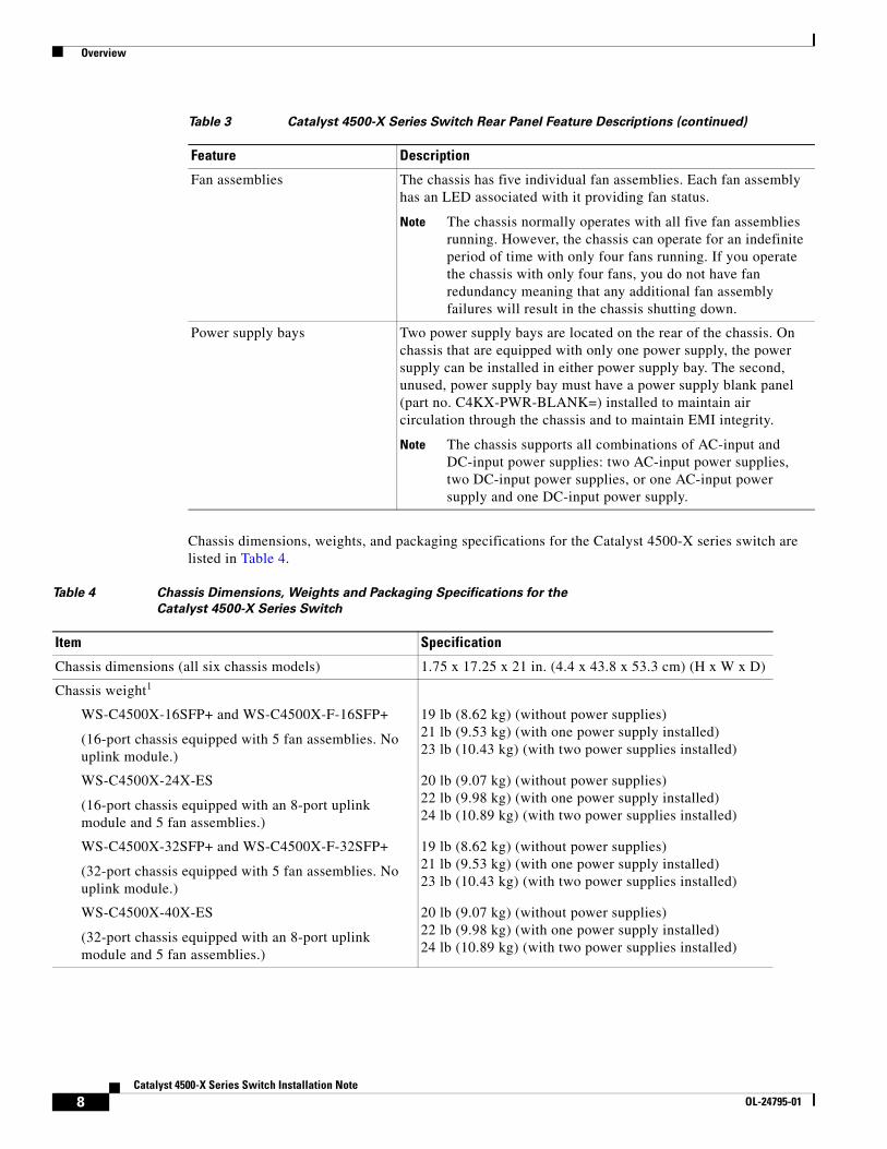
Chassis dimensions, weights, and packaging specifications for the Catalyst 4500-X series switch are listed in Table 4.
Fan assemblies The chassis has five individual fan assemblies. Each fan assembly has an LED associated with it providing fan status.
Note The chassis normally operates with all five fan assemblies running. However, the chassis can operate for an indefinite period of time with only four fans running. If you operate the chassis with only four fans, you do not have fan redundancy meaning that any additional fan assembly failures will result in the chassis shutting down.
Power supply bays Two power supply bays are located on the rear of the chassis. On chassis that are equipped with only one power supply, the power supply can be installed in either power supply bay. The second, unused, power supply bay must have a power supply blank panel (part no. C4KX-PWR-BLANK=) installed to maintain air circulation through the chassis and to maintain EMI integrity.
Note The chassis supports all combinations of AC-input and DC-input power supplies: two AC-input power supplies, two DC-input power supplies, or one AC-input power supply and one DC-input power supply.
Table 3 Catalyst 4500-X Series Switch Rear Panel Feature Descriptions (continued)
Feature Description
Table 4 Chassis Dimensions, Weights and Packaging Specifications for the
Catalyst 4500-X Series Switch
Item Specification
Chassis dimensions (all six chassis models) 1.75 x 17.25 x 21 in. (4.4 x 43.8 x 53.3 cm) (H x W x D)
Chassis weight1
WS-C4500X-16SFP+ and WS-C4500X-F-16SFP+
(16-port chassis equipped with 5 fan assemblies. No uplink module.)
19 lb (8.62 kg) (without power supplies)21 lb (9.53 kg) (with one power supply installed)23 lb (10.43 kg) (with two power supplies installed)
WS-C4500X-24X-ES
(16-port chassis equipped with an 8-port uplink module and 5 fan assemblies.)
20 lb (9.07 kg) (without power supplies)22 lb (9.98 kg) (with one power supply installed)24 lb (10.89 kg) (with two power supplies installed)
WS-C4500X-32SFP+ and WS-C4500X-F-32SFP+
(32-port chassis equipped with 5 fan assemblies. No uplink module.)
19 lb (8.62 kg) (without power supplies)21 lb (9.53 kg) (with one power supply installed)23 lb (10.43 kg) (with two power supplies installed)
WS-C4500X-40X-ES
(32-port chassis equipped with an 8-port uplink module and 5 fan assemblies.)
20 lb (9.07 kg) (without power supplies)22 lb (9.98 kg) (with one power supply installed)24 lb (10.89 kg) (with two power supplies installed)
8Catalyst 4500-X Series Switch Installation Note
OL-24795-01
Safety
Shipping box dimensions and packaged shipping weights for the replaceable assemblies on the Catalyst 4500-X switch are provided in Table 5.
SafetySafety warnings appear throughout this publication in procedures that may harm you if performed incorrectly. A warning symbol precedes each warning statement. The warnings below are general warnings that are applicable to the entire publication.
Shipping package dimensions (all six chassis models) 5.75 x 21.13 x 28.63 in. (14.60 x 53.67 x 72.72 cm)(H x W x D)
Shipping weight1
WS-C4500X-16SFP+ and WS-C4500X-F-16SFP+WS-C4500X-32SFP+ and WS-C4500X-F-32SFP+
27.5 lb (12.47 kg)
WS-C4500X-24X-ES and WS-C4500X-40X-ES 30.5 lb (13.83 kg)
1. Chassis weights can vary slightly based on the configuration.
Table 4 Chassis Dimensions, Weights and Packaging Specifications for the
Catalyst 4500-X Series Switch (continued)
Item Specification
Table 5 Catalyst 4500-X FRU Shipping Box Dimensions and Shipping Weight
FRU Assembly Shipping Box Dimensions (H x W x D) Total Shipping Weight
750 W AC-input power supply(C4KX-PWR-750AC-R= and C4KX-PWR-750AC-F=)
4.38 x 7.13 x 20.13 in (11.13 x 18.11 x 51.13 cm)
3.7 lb (1.68 kg)
750 W DC-input power supply(C4KX-PWR-750DC-R= and C4KX-PWR-750DC-F=)
4.38 x 7.13 x 20.13 in (11.13 x 18.11 x 51.13 cm)
3.7 lb (1.68 kg)
Fan assembly(C4KX-FAN-R= and C4KX-FAN-F=)
2.25 x 7.00 x 8.50 in (5.72 x 17.78 x 21.59 cm)
0.7 lb (0.32 kg)
Network uplink module(C4KX-NM-8SFP+=)
3.00 x 10.00 x 14.88 in(7.62 x 25.40 x 37.80 cm)
1.85 lb (0.84 kg)
9Catalyst 4500-X Series Switch Installation Note
OL-24795-01
Safety
Statement 1071—Warning Definition
Warning IMPORTANT SAFETY INSTRUCTIONS
This warning symbol means danger. You are in a situation that could cause bodily injury. Before you work on any equipment, be aware of the hazards involved with electrical circuitry and be familiar with standard practices for preventing accidents. Use the statement number provided at the end of each warning to locate its translation in the translated safety warnings that accompanied this device.
SAVE THESE INSTRUCTIONS
Waarschuwing BELANGRIJKE VEILIGHEIDSINSTRUCTIES
Dit waarschuwingssymbool betekent gevaar. U verkeert in een situatie die lichamelijk letsel kan veroorzaken. Voordat u aan enige apparatuur gaat werken, dient u zich bewust te zijn van de bij elektrische schakelingen betrokken risico's en dient u op de hoogte te zijn van de standaard praktijken om ongelukken te voorkomen. Gebruik het nummer van de verklaring onderaan de waarschuwing als u een vertaling van de waarschuwing die bij het apparaat wordt geleverd, wilt raadplegen.
BEWAAR DEZE INSTRUCTIES
Varoitus TÄRKEITÄ TURVALLISUUSOHJEITA
Tämä varoitusmerkki merkitsee vaaraa. Tilanne voi aiheuttaa ruumiillisia vammoja. Ennen kuin käsittelet laitteistoa, huomioi sähköpiirien käsittelemiseen liittyvät riskit ja tutustu onnettomuuksien yleisiin ehkäisytapoihin. Turvallisuusvaroitusten käännökset löytyvät laitteen mukana toimitettujen käännettyjen turvallisuusvaroitusten joukosta varoitusten lopussa näkyvien lausuntonumeroiden avulla.
SÄILYTÄ NÄMÄ OHJEET
Attention IMPORTANTES INFORMATIONS DE SÉCURITÉ
Ce symbole d'avertissement indique un danger. Vous vous trouvez dans une situation pouvant entraîner des blessures ou des dommages corporels. Avant de travailler sur un équipement, soyez conscient des dangers liés aux circuits électriques et familiarisez-vous avec les procédures couramment utilisées pour éviter les accidents. Pour prendre connaissance des traductions des avertissements figurant dans les consignes de sécurité traduites qui accompagnent cet appareil, référez-vous au numéro de l'instruction situé à la fin de chaque avertissement.
CONSERVEZ CES INFORMATIONS
10Catalyst 4500-X Series Switch Installation Note
OL-24795-01
Safety
Warnung WICHTIGE SICHERHEITSHINWEISE
Dieses Warnsymbol bedeutet Gefahr. Sie befinden sich in einer Situation, die zu Verletzungen führen kann. Machen Sie sich vor der Arbeit mit Geräten mit den Gefahren elektrischer Schaltungen und den üblichen Verfahren zur Vorbeugung vor Unfällen vertraut. Suchen Sie mit der am Ende jeder Warnung angegebenen Anweisungsnummer nach der jeweiligen Übersetzung in den übersetzten Sicherheitshinweisen, die zusammen mit diesem Gerät ausgeliefert wurden.
BEWAHREN SIE DIESE HINWEISE GUT AUF.
Avvertenza IMPORTANTI ISTRUZIONI SULLA SICUREZZA
Questo simbolo di avvertenza indica un pericolo. La situazione potrebbe causare infortuni alle persone. Prima di intervenire su qualsiasi apparecchiatura, occorre essere al corrente dei pericoli relativi ai circuiti elettrici e conoscere le procedure standard per la prevenzione di incidenti. Utilizzare il numero di istruzione presente alla fine di ciascuna avvertenza per individuare le traduzioni delle avvertenze riportate in questo documento.
CONSERVARE QUESTE ISTRUZIONI
Advarsel VIKTIGE SIKKERHETSINSTRUKSJONER
Dette advarselssymbolet betyr fare. Du er i en situasjon som kan føre til skade på person. Før du begynner å arbeide med noe av utstyret, må du være oppmerksom på farene forbundet med elektriske kretser, og kjenne til standardprosedyrer for å forhindre ulykker. Bruk nummeret i slutten av hver advarsel for å finne oversettelsen i de oversatte sikkerhetsadvarslene som fulgte med denne enheten.
TA VARE PÅ DISSE INSTRUKSJONENE
Aviso INSTRUÇÕES IMPORTANTES DE SEGURANÇA
Este símbolo de aviso significa perigo. Você está em uma situação que poderá ser causadora de lesões corporais. Antes de iniciar a utilização de qualquer equipamento, tenha conhecimento dos perigos envolvidos no manuseio de circuitos elétricos e familiarize-se com as práticas habituais de prevenção de acidentes. Utilize o número da instrução fornecido ao final de cada aviso para localizar sua tradução nos avisos de segurança traduzidos que acompanham este dispositivo.
GUARDE ESTAS INSTRUÇÕES
¡Advertencia! INSTRUCCIONES IMPORTANTES DE SEGURIDAD
Este símbolo de aviso indica peligro. Existe riesgo para su integridad física. Antes de manipular cualquier equipo, considere los riesgos de la corriente eléctrica y familiarícese con los procedimientos estándar de prevención de accidentes. Al final de cada advertencia encontrará el número que le ayudará a encontrar el texto traducido en el apartado de traducciones que acompaña a este dispositivo.
GUARDE ESTAS INSTRUCCIONES
11Catalyst 4500-X Series Switch Installation Note
OL-24795-01
Safety
Varning! VIKTIGA SÄKERHETSANVISNINGAR
Denna varningssignal signalerar fara. Du befinner dig i en situation som kan leda till personskada. Innan du utför arbete på någon utrustning måste du vara medveten om farorna med elkretsar och känna till vanliga förfaranden för att förebygga olyckor. Använd det nummer som finns i slutet av varje varning för att hitta dess översättning i de översatta säkerhetsvarningar som medföljer denna anordning.
SPARA DESSA ANVISNINGAR
12Catalyst 4500-X Series Switch Installation Note
OL-24795-01
Safety
Aviso INSTRUÇÕES IMPORTANTES DE SEGURANÇA
Este símbolo de aviso significa perigo. Você se encontra em uma situação em que há risco de lesões corporais. Antes de trabalhar com qualquer equipamento, esteja ciente dos riscos que envolvem os circuitos elétricos e familiarize-se com as práticas padrão de prevenção de acidentes. Use o número da declaração fornecido ao final de cada aviso para localizar sua tradução nos avisos de segurança traduzidos que acompanham o dispositivo.
GUARDE ESTAS INSTRUÇÕES
Advarsel VIGTIGE SIKKERHEDSANVISNINGER
Dette advarselssymbol betyder fare. Du befinder dig i en situation med risiko for legemesbeskadigelse. Før du begynder arbejde på udstyr, skal du være opmærksom på de involverede risici, der er ved elektriske kredsløb, og du skal sætte dig ind i standardprocedurer til undgåelse af ulykker. Brug erklæringsnummeret efter hver advarsel for at finde oversættelsen i de oversatte advarsler, der fulgte med denne enhed.
GEM DISSE ANVISNINGER
13Catalyst 4500-X Series Switch Installation Note
OL-24795-01
Safety
14Catalyst 4500-X Series Switch Installation Note
OL-24795-01
Safety
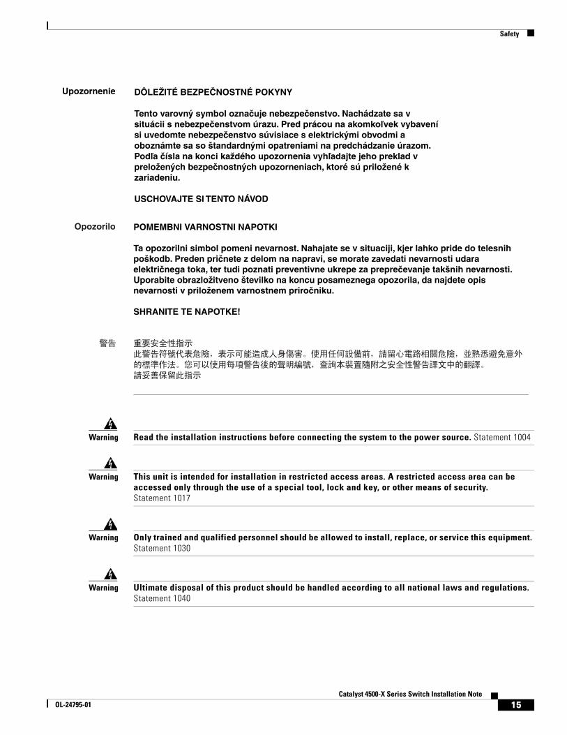
Warning Read the installation instructions before connecting the system to the power source. Statement 1004
Warning This unit is intended for installation in restricted access areas. A restricted access area can be accessed only through the use of a special tool, lock and key, or other means of security. Statement 1017
Warning Only trained and qualified personnel should be allowed to install, replace, or service this equipment. Statement 1030
Warning Ultimate disposal of this product should be handled according to all national laws and regulations. Statement 1040
15Catalyst 4500-X Series Switch Installation Note
OL-24795-01
Site Requirements
Warning Voltages that present a shock hazard may exist on Power over Ethernet (PoE) circuits if interconnections are made using uninsulated exposed metal contacts, conductors, or terminals. Avoid using such interconnection methods, unless the exposed metal parts are located within a restricted access location and users and service people who are authorized within the restricted access location are made aware of the hazard. A restricted access area can be accessed only through the use of a special tool, lock and key or other means of security. Statement 1072
Site RequirementsThe following sections describe the basic site requirements that you should be aware of as you prepare to install your Catalyst 4500-X series switch:
• Rack-Mounting Guidelines, page 16
• Temperature, page 17
• Airflow, page 18
• Humidity, page 19
• Altitude, page 19
• Dust and Particulates, page 19
• Corrosion, page 20
• Electromagnetic and Radio Frequency Interference, page 20
• Shock and Vibration, page 21
• Power Source Interruptions, page 21
• System Grounding, page 21
• Maintaining Safety with Electricity, page 23
• Preventing Electrostatic Discharge Damage, page 24
Rack-Mounting GuidelinesA rack-mount kit (C4948E-ACC-KIT) is included in your switch chassis accessory kit for mounting the switch in a standard 19-inch (48.3 cm) equipment rack.
Note This kit might not suitable for use in equipment racks with obstructions (such as power strips) that could impair access to the switch.
Before rack-mounting the switch, ensure the following:
• The width of the rack, between the two front-mounting strips or rails, must be 17.75 inches (45.09 cm).
• The depth of the rack, between the front- and rear-mounting strips, must be at least 19.25 inches (48.9 cm) but not more than 32.5 inches (82.5 cm).
• The rack must have sufficient vertical clearance to insert the chassis. The chassis height is 1 U (1.75 inches (4.4 cm)).
16Catalyst 4500-X Series Switch Installation Note
OL-24795-01
Site Requirements
• The equipment rack is stable, sturdy, and is in no danger of tipping over.
– Install heavier equipment in the lower half of the rack to maintain a low center of gravity and prevent the rack from becoming top-heavy and tipping over.
• The equipment rack is properly ventilated.
– Install the chassis in an enclosed rack only if it has adequate ventilation or an exhaust fan; use an open rack whenever possible.
– Ensure that the ambient temperature of the rack environment does not exceed a maximum temperature of 104° F (40° C). If the switch is installed in a closed or multiunit rack assembly, the ambient operating temperature of the rack environment might be higher than the ambient room temperature.
– Ensure that the ventilation system in a closed rack does not prevent cooling by creating negative pressure around the chassis and redirecting the air away from the chassis intake vent. If necessary, operate the chassis with the rack open.
– Ensure that equipment installed near the bottom of a rack does not generate excessive heat, which can be drawn upward and into the air intakes of equipment above. This situation can cause overtemperature conditions in the chassis at or near the top of the rack.
– Consider the equipment and cabling that is already installed in the rack. Ensure that cables from other equipment will not obstruct the airflow through the chassis or impair access to the power supplies or switching modules. Route cables away from field-replaceable components to avoid disconnecting cables unnecessarily for equipment maintenance or upgrades.
– Allow at least 3 to 4 feet (91 to 122 cm) of clearance behind the rack for maintenance and removal of switch assemblies. If the rack is mobile, you can push it back within 1 foot (30.45 cm) of a wall or cabinet for normal operation and pull it out when necessary for maintenance.
TemperatureTemperature extremes can cause a system to operate at reduced efficiency and cause a variety of problems, including premature aging and failure of chips, and failure of mechanical devices. Extreme temperature fluctuations can cause chips to become loose in their sockets. Observe the following guidelines:
• Ensure that the system is operating in an environment no colder than 50°F (10°C) or hotter than 104°F (40°C).
• Ensure that the chassis has adequate ventilation.
• Use proper air circulation management techniques. Chassis mounted higher in a rack enclosure are susceptible to higher ambient air temperatures due to the heat generated from chassis that are mounted below the chassis in the rack.
• Do not place the chassis within a closed-in wall unit or on top of cloth, which can act as insulation.
• Do not place the chassis where it will receive direct sunlight, particularly in the afternoon.
• Do not place the chassis next to a heat source of any kind, including heating vents.
17Catalyst 4500-X Series Switch Installation Note
OL-24795-01
Site Requirements
• Ensure that all slots and openings on a chassis remain unobstructed, especially the fan assembly vent at the back of the chassis. Adequate ventilation is particularly important at high altitudes where the air is thinner.
• Clean the installation site at regular intervals to avoid buildup of dust and debris, which can cause a system to overheat.
• Allow a 2-hour warm-up period to bring the chassis up to normal operating temperature before turning it on for chassis that have been exposed to abnormally cold temperatures.
Failure to observe these guidelines can damage internal chassis components.
Note The Catalyst 4500-X series switches are equipped with internal air temperature sensors that are triggered at 104°F (40°C) generating a minor alarm and at 131°F (55°C) generating a major alarm.
AirflowThe Catalyst 4500-X series switch is designed to be installed in an environment where there is a sufficient volume of air available to cool the chassis and the power supplies. Any constraints placed on the free flow of air through the chassis or an elevated ambient air temperature can cause the switch to overheat and shut down.
To maintain proper air circulation through the switch chassis, we recommend that you maintain a minimum 6-inch (15 cm) separation between a wall and the chassis hot air exhaust. Failure to maintain adequate spacing between chassis can cause the switch chassis that is drawing in the hot exhaust air to overheat and fail.
If your chassis is equipped with only one power supply (either AC-input or DC-input), you must have a blank power supply cover (part no. C4KX-PWR-BLANK=) installed over the empty power supply bay to maintain proper airflow through the chassis.
If your chassis does not have the uplink module installed, you must have a blank uplink module cover (part no. C4KX-NM-BLANK=) installed over the empty uplink module bay to maintain proper airflow through the chassis.
If you are installing your Catalyst 4500-X series switch chassis in an enclosed or partially enclosed rack, we strongly recommend that you verify that your site meets the following guidelines:
• Verify that the ambient air temperature within the enclosed or partially enclosed rack is within the chassis operating temperature limits. After installing the chassis in the rack, power up the chassis and allow the chassis temperature to stabilize (approximately 2 hours). Measure the ambient air temperature at the chassis air intake grill and at the chassis air exhaust grill by positioning an external temperature probe approximately 1 inch (2.5 cm) away from the grills.
– If the ambient intake air temperature is less than 104°F (40°C), the rack meets the intake air temperature criterion.
– If the ambient intake air temperature exceeds 104°F (40°C), the system might experience minor temperature alarms and is in danger of overheating. Prolonged operation at a temperature in excess of 104°F (40°C) might severely affect the long-term reliability of the equipment.
– If the ambient intake air temperature equals or is greater than 131°F (55°C), the system will experience a major temperature alarm and shut down.
18Catalyst 4500-X Series Switch Installation Note
OL-24795-01
Site Requirements
• Verify that the enclosed or partially enclosed rack allows an adequate flow of air through the switch chassis as follows:
– If the difference between the measured intake air temperature and the exhaust air temperature does not exceed 10°C, there is sufficient airflow in the rack.
– If the difference in air temperature exceeds 10°C, there is insufficient airflow to cool the chassis.
Note The 10°C temperature differential between the intake and the exhaust must be determined by taking measurements using external digital temperature probes. Do not use the chassis internal temperature sensors to measure the temperature differential.
• Plan for future growth. Your Catalyst 4500-X series switch currently installed in an enclosed or partially enclosed rack might meet ambient air temperature and airflow requirements now. However, if you add more chassis or other equipment to the rack, the additional heat generated might cause the ambient air temperature within the rack to exceed 104°F (40°C) and can cause minor alarms.
HumidityHigh-humidity conditions can cause moisture migration and penetration into the system. This moisture can cause corrosion of internal components and degradation of properties such as electrical resistance, thermal conductivity, physical strength, and size. Extreme moisture buildup inside the system can result in electrical shorts, which can cause serious damage to the system. Each system is rated to operate at 8 to 80 percent relative humidity, with a humidity gradation of 10 percent per hour. In storage, a system can withstand from 5 to 95 percent relative humidity. Buildings in which climate is controlled by air-conditioning in the warmer months and by heat during the colder months usually maintain an acceptable level of humidity for system equipment. However, if a system is located in an unusually humid location, a dehumidifier can be used to maintain the humidity within an acceptable range.
AltitudeOperating a system at high altitude (low pressure) reduces the efficiency of forced and convection cooling and can result in electrical problems related to arcing and corona effects. This condition can also cause sealed components with internal pressure, such as electrolytic capacitors, to fail or perform at reduced efficiency. Each system is rated to operate at altitudes from –50 to 6500 feet (–16 to 1981 meters) and can be stored at altitudes of –50 to 35,000 feet (–16 to 10,668 meters).
Dust and ParticulatesFans cool the power supplies and the system components by drawing in room temperature air, circulating the air through the power supplies and the chassis, and exhausting the heated air out through various openings in the chassis. However, fans also ingest dust and other particulates, causing contaminant buildup on the fan blades and in the system, which create a thermal blanket on components increasing the internal chassis temperature.
19Catalyst 4500-X Series Switch Installation Note
OL-24795-01
Site Requirements
A clean operating environment can greatly reduce the negative effects of dust and other particulates. The standards listed below provide guidelines for acceptable working environments and acceptable levels of suspended particulate matter:
• Network Equipment Building Systems (NEBS) GR-63-CORE
• National Electrical Manufacturers Association (NEMA) Type 1
• International Electrotechnical Commission (IEC) IP-20
CorrosionCorrosion of system connectors is a gradual process that can eventually lead to intermittent failures of electrical circuits. The oil from a person’s fingers or prolonged exposure to high temperature or humidity can corrode the gold-plated edge connectors and pin connectors on various components in the system. To prevent corrosion, avoid touching contacts on boards and cards, and protect the system from extreme temperatures and moist, salty environments.
Electromagnetic and Radio Frequency InterferenceElectromagnetic interference (EMI) and radio frequency interference (RFI) from a system can adversely affect devices such as radio and television (TV) receivers operating near the system. Radio frequencies emanating from a system can also interfere with cordless and low-power telephones. Conversely, RFI from high-power telephones can cause spurious characters to appear on the system monitor. RFI is defined as any EMI with a frequency above 10 kilohertz (kHz). This type of interference can travel from the system to other devices through the power cable and power source or through the air like transmitted radio waves. The Federal Communications Commission (FCC) publishes specific regulations to limit the amount of EMI and RFI emitted by computing equipment. Each system meets these FCC regulations. To reduce the possibility of EMI and RFI, follow these guidelines:
• Operate the system with the chassis covers installed.
• Ensure that an unused power supply bay has the blank cover plate installed.
• If you do not have the optional network uplink module installed, make sure that the unused bay has a blank panel installed.
When wires are run for any significant distance in an electromagnetic field, interference can occur between the field and the signals on the wires. This fact has two implications for the construction of plant wiring:
• Bad wiring practice can result in radio interference emanating from the plant wiring.
• Strong EMI, especially when it is caused by lightning or radio transmitters, can destroy the signal drivers and receivers in the chassis, and even create an electrical hazard by conducting power surges through lines into equipment.
Note To predict and remedy strong EMI, you may also need to consult experts in radio frequency interference (RFI).
If you use twisted-pair cable in your plant wiring with a good distribution of grounding conductors, the plant wiring is unlikely to emit radio interference.
20Catalyst 4500-X Series Switch Installation Note
OL-24795-01
Site Requirements
Caution Category 5e, Category 6, and Category 6a cables can store large levels of static electricity because of the dielectric properties of the materials used in their construction. We recommend that you momentarily ground the cables (especially in new cable runs) to a suitable and safe earth ground before connecting them to the port.
If the wires exceed the recommended distances, or if wires pass between buildings, give special consideration to the effect of a lightning strike in your vicinity. The electromagnetic pulse caused by lightning or other high-energy phenomena can easily couple enough energy into unshielded conductors to destroy electronic devices. If you previously have had similar problems, you might want to consult experts in electrical surge suppression and shielding.
Shock and VibrationCatalyst 4500-X series switches have been shock- and vibration-tested for operating ranges, handling, and earthquake standards to NEBS (Zone 4 per GR-63-Core). These tests have been conducted in earthquake environment and criteria, office vibration and criteria, transportation vibration and criteria, and packaged equipment shock.
Power Source InterruptionsSystems are especially sensitive to variations in voltage supplied by the AC power source. Overvoltage, undervoltage, and transients (or spikes) can erase data from memory or even cause components to fail. To protect against these types of problems, power cables should always be properly grounded. Also, place the system on a dedicated power circuit (rather than sharing a circuit with other heavy electrical equipment). Besides these appliances, the greatest threats to a system power supply are surges or blackouts that are caused by electrical storms. Whenever possible, turn off the system and any peripherals, and unplug them from their power sources during thunderstorms. If a blackout occurs—even a temporary one—while the system is turned on, turn off the system immediately and disconnect it from the electrical outlet. Leaving the system on may cause problems when the power is restored; all other appliances left on in the area can create large voltage spikes that can damage the system.
System GroundingWe recommend that you install a NEBS-compliant system ground as part of the chassis installation process. Chassis installations that rely only on the AC third-prong ground are insufficient to properly and adequately ground the systems. The chassis comes with a ground lug and two M4 bolts as part of the accessory kit. The lug attaches to the chassis grounding pad with the two bolts. A properly sized copper wire (not provided) should be used to connect the ground lug to the NEBS-compliant building ground.
Proper grounding practices ensure that the buildings and the installed equipment within them have low-impedance connections and low-voltage differentials between chassis. When you include NEBS-compliant system grounds, you reduce or prevent shock hazards, greatly reduce the chances of equipment damage due to transients, and substantially reduce the potential for data corruption.
Without proper and complete system grounding, you run the risk of increased component damage due to ESD. Additionally, you have a greatly increased chance of data corruption, system lockup and frequent system reboot situations by not using a system (NEBS compliant) ground.
21Catalyst 4500-X Series Switch Installation Note
OL-24795-01
Site Requirements
Warning This equipment must be grounded. Never defeat the ground conductor or operate the equipment in the absence of a suitably installed ground conductor. Contact the appropriate electrical inspection authority or an electrician if you are uncertain that suitable grounding is available. Statement 1024
Caution Installations that rely solely on system grounding using only an AC third-prong ground run a substantially greater risk of equipment problems and data corruption than those installations that use both the AC third-prong ground and a properly installed system (NEBS compliant) ground.
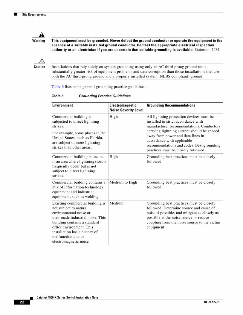
Table 6 lists some general grounding practice guidelines.
Table 6 Grounding Practice Guidelines
Environment Electromagnetic Noise Severity Level
Grounding Recommendations
Commercial building is subjected to direct lightning strikes.
For example, some places in the United States, such as Florida, are subject to more lightning strikes than other areas.
High All lightning protection devices must be installed in strict accordance with manufacturer recommendations. Conductors carrying lightning current should be spaced away from power and data lines in accordance with applicable recommendations and codes. Best grounding practices must be closely followed.
Commercial building is located in an area where lightning storms frequently occur but is not subject to direct lightning strikes.
High Grounding best practices must be closely followed.
Commercial building contains a mix of information technology equipment and industrial equipment, such as welding.
Medium to High Grounding best practices must be closely followed.
Existing commercial building is not subject to natural environmental noise or man-made industrial noise. This building contains a standard office environment. This installation has a history of malfunction due to electromagnetic noise.
Medium Grounding best practices must be closely followed. Determine source and cause of noise if possible, and mitigate as closely as possible at the noise source or reduce coupling from the noise source to the victim equipment.
22Catalyst 4500-X Series Switch Installation Note
OL-24795-01
Site Requirements
Note In all situations, grounding practices must comply with Section 250 of the National Electric Code (NEC) requirements or local laws and regulations. A 6 AWG grounding wire is preferred from the chassis to the rack ground or directly to the common bonding network (CBN). The equipment rack should also be connected to the CBN with 6 AWG grounding wire.
Maintaining Safety with ElectricityWhen working on electrical equipment, follow these guidelines:
• Do not work alone if potentially hazardous conditions exist anywhere in your work space.
• Never assume that power is disconnected from a circuit; always check the circuit before working on it.
• Look carefully for possible hazards in your work area, such as damp floors, ungrounded power extension cables, frayed or damaged power cords, and missing safety grounds.
• If an electrical accident occurs, proceed as follows:
– Use extreme caution; do not become a victim yourself.
– Disconnect power from the system.
– If possible, send another person to get medical aid. Otherwise, assess the condition of the victim, and then call for help.
– Determine if the person needs rescue breathing or external cardiac compressions; then take appropriate action.
• Use the product within its marked electrical ratings and product usage instructions.
• Install the product in compliance with local and national electrical codes.
New commercial building is not subject to natural environmental noise or man-made industrial noise. This building contains a standard office environment.
Low Grounding best practices should be followed as closely as possible. Electromagnetic noise problems are not anticipated, but installing a best practice grounding system in a new building is often the least expensive route and the best way to plan for the future.
Existing commercial building is not subject to natural environmental noise or man-made industrial noise. This building contains a standard office environment.
Low Grounding best practices should be followed as much as possible. Electromagnetic noise problems are not anticipated, but installing a best practice grounding system is always recommended.
Table 6 Grounding Practice Guidelines (continued)
Environment Electromagnetic Noise Severity Level
Grounding Recommendations
23Catalyst 4500-X Series Switch Installation Note
OL-24795-01
Site Requirements
• If any of the following conditions occur, contact the Cisco Technical Assistance Center:
– The power cable or plug is damaged.
– An object has fallen into the product.
– The product has been exposed to water or other liquids.
– The product has been dropped or shows signs of damage.
– The product does not operate correctly when you follow the operating instructions.
• Use the correct external power source. Operate the product only from the type of power source indicated on the electrical ratings label. If you are not sure of the type of power source required, consult the Cisco Technical Assistance Center or a local electrician.
• Use approved power cables only. You have been provided with one or more power cables with your chassis power supply that are intended for use in your country, based on the shipping location. Should you need to purchase additional power cables, ensure that they are rated for the product and for the voltage and current marked on the product’s electrical ratings label. The voltage and current rating of the power cable should be greater than the ratings marked on the label.
• To help prevent electrical shock, plug all power cables into properly grounded electrical outlets.
• Observe power strip ratings. Make sure that the total current rating of all products that are plugged into the power strip does not exceed 80 percent of the power strip rating.
• Do not modify power cables or plugs yourself. Consult with a licensed electrician or your power company for site modifications. Always follow your local and national wiring codes.
Preventing Electrostatic Discharge DamageElectrostatic discharge (ESD) damage, which can occur when modules or other FRUs are improperly handled, results in intermittent or complete failures. Modules consist of printed circuit boards that are fixed in metal carriers. Electromagnetic interference (EMI) shielding and connectors are integral components of the carrier. Although the metal carrier helps to protect the board from ESD, always use an ESD grounding strap when handling modules.
To prevent ESD damage, follow these guidelines:
• Always use an ESD wrist strap and ensure that it makes maximum contact with bare skin. ESD grounding straps are available with banana plugs, metal spring clips, or alligator clips. If you choose to use the disposable ESD wrist strap supplied with most FRUs or an ESD wrist strap equipped with an alligator clip, you must attach the system ground lug to the chassis in order to provide a proper grounding point for the ESD wrist strap.
Note This system ground is also referred to as the network equipment building system (NEBS) ground.
• If your chassis does not have the system ground attached, you must install the system ground.
24Catalyst 4500-X Series Switch Installation Note
OL-24795-01
Power Requirements
After you install the system ground lug, follow these steps to correctly attach the ESD wrist strap:
Step 1 Attach the ESD wrist strap to bare skin as follows:
a. If you are using the ESD wrist strap supplied with the FRUs, open the wrist strap package and unwrap the ESD wrist strap. Place the black conductive loop over your wrist and tighten the strap so that it makes good contact with your bare skin.
b. If you are using an ESD wrist strap equipped with an alligator clip, open the package and remove the ESD wrist strap. Locate the end of the wrist strap that attaches to your body and secure it to your bare skin.
Step 2 Grasp the spring or alligator clip on the ESD wrist strap and momentarily touch the clip to a bare metal spot (unpainted surface) on the rack. We recommend that you touch the clip to an unpainted rack rail so that any built-up static charge is then safely dissipated to the entire rack.
Step 3 Attach either the spring clip or the alligator clip to the ground lug screw as follows:
a. If you are using the ESD wrist strap that is supplied with the FRUs, squeeze the spring clip jaws open, position the spring clip to one side of the system ground lug screw head, and slide the spring clip over the lug screw head so that the spring clip jaws close behind the lug screw head.
Note The spring clip jaws do not open wide enough to fit directly over the head of the lug screw or the lug barrel.
b. If you are using an ESD wrist strap that is equipped with an alligator clip, attach the alligator clip directly over the head of the system ground lug screw or to the system ground lug barrel.
Caution For safety, periodically check the resistance value of the antistatic strap. The measurement should be between 1 and 10 megohm (Mohm).
Power RequirementsWhen preparing your site for the switch installation, follow these general requirements:
• In systems configured with two power supplies, connect each of the two power supplies to a separate input power source. If you fail to do this, your system might be susceptible to total power failure due to a fault in the external wiring or a tripped circuit breaker.
• To prevent a loss of input power, be sure that the total maximum load on each source circuit is within the current ratings of the wiring and breakers.
• In some systems, you may decide to use an uninterruptible power supply (UPS) to protect against power failures at your site. Be aware when selecting a UPS that some UPS models that use ferroresonant technology can become unstable when operating with the power supplies which use power factor correction (PFC). This can cause the output voltage waveform to the switch to become distorted resulting in an undervoltage situation in the system.
25Catalyst 4500-X Series Switch Installation Note
OL-24795-01
Power Requirements
Warning This product relies on the building’s installation for short-circuit (overcurrent) protection. Ensure that the protective device is rated not greater than: 20 A for AC systems, 30 A for DC systems Statement 1005
Warning This unit might have more than one power supply connection. All connections must be removed to de-energize the unit. Statement 1028
Warning This product requires short-circuit (overcurrent) protection, to be provided as part of the building installation. Install only in accordance with national and local wiring regulations. Statement 1045
This section includes the following topics:
• Power Connection Guidelines for AC-Powered Systems, page 26
• Power Connection Guidelines for DC-Powered Systems, page 26
• Cabling Requirements, page 27
Power Connection Guidelines for AC-Powered SystemsThis section provides some basic guidelines for connecting the AC power supplies to the site power source:
• It is recommended that each chassis power supply should have a separate, dedicated branch circuit.
– (North America)—It is recommended that the AC-input power supply operate on a 15 A circuit.
– (International)—Circuits should be sized according to local and national codes.
• If you are using a 200/240 VAC power source in North America, the circuit must be protected by a two-pole circuit breaker.
• Make sure that your power cord can easily reach from the chassis power supply to the source AC outlet. The AC power cords come in standard lengths of 6 feet (1.8 meters) and 8 feet 2 inches (2.5 m). The source AC outlet should be easily accessible.
• The AC power receptacles used to plug in the chassis must be the grounding type. The grounding conductors that connect to the receptacles should connect to protective earth ground at the service equipment.
Power Connection Guidelines for DC-Powered SystemsThis section provides the basic guidelines for connecting the Catalyst 4500-X series switch DC-input power supplies to the site power source:
• All power connection wiring should conform to the rules and regulations in the National Electrical Code (NEC), as well as any local codes.
• The DC return must remain isolated from the system frame and the chassis (DC-I).
26Catalyst 4500-X Series Switch Installation Note
OL-24795-01
Power Requirements
• For DC power cables, we recommend that you use commensurately rated, high-strand-count copper wire cable. Connection to the DC-input power supply requires one source DC (–), and one source DC return (+). The length of the cables depends on your switch location. The cables required to attach the source DC cables to the power supply are not available from Cisco Systems; they are available from any commercial cable vendor.
• The color coding of the source DC power cable leads depends on the color coding of the site DC power source. Because there is no color code standard for source DC wiring, you must ensure that the power cables are connected to the DC-input power supply terminal block in the proper (+) and (–) polarity. In some cases, the source DC cable leads might have a positive (+) or a negative (–) label. This label is a relatively safe indication of the polarity, but you must verify the polarity by measuring the voltage between the DC cable leads. When making the measurement, the positive (+) lead and the negative (–) lead must always match the (+) and (–) labels on the DC-input power supply terminal block.
• The circuit breaker is considered to be the disconnect device and should be easily accessible.
• The circuit must be protected by a dedicated two-pole circuit breaker. The circuit breaker should be sized according to the power supply input rating and local or national code requirements.
Cabling Requirements
Caution The intrabuilding port(s) of the equipment or subassembly is suitable for connection to intrabuilding or unexposed wiring or cabling only. The intrabuilding port(s) of the equipment or subassembly must not be metallically connected to interfaces that connect to the Outside Plant (OSP) or its wiring. These interfaces are designed for use as intrabuilding interfaces only (Type 2 or Type 4 ports as described in GR-1089-CORE, Issue 4) and require isolation from the exposed OSP cabling. The addition of Primary Protectors is not sufficient protection to connect these interfaces metallically to OSP wiring.
When running power and data cables together in overhead cable trays or subfloor cable trays, be aware of the following caution:
Caution We recommend that power cabling runs and other potential noise sources be located as far away as practical from LAN cabling that terminates on Cisco equipment. In situations, where this type of long parallel cable runs exist, which cannot be separated by at least 3.3 feet (1 meter), we recommend that you shield these potential noise sources. To avoid interference, the source should be shielded by housing it in a grounded metallic conduit.
Also be aware of the following caution concerning the use of Category 5e and Category 6 Ethernet cables:
Caution Category 5e, Category 6, and Category 6a cables can store large levels of static electricity because of the dielectric properties of the materials used in their construction. We recommend that you momentarily ground the cables (especially in new cable runs) to a suitable and safe earth ground before connecting them to the port.
27Catalyst 4500-X Series Switch Installation Note
OL-24795-01
Rack Mounting Kits
Rack Mounting KitsTable 7 lists the rack mount kits that are available for use with the Catalyst 4500-X series switch chassis.
Tools RequiredThe following tools are needed to install the chassis in the rack:
• Phillips-head screwdriver
• Torque wrench with a Phillips-head bit
Note The torque wrench must be properly calibrated to ensure that correct torque values are applied to the installation screws.
• Tape measure
• Level
Installing the Chassis in an Equipment Rack Using the Standard Rack-Mount Kit
Use this rack mount kit when you are installing the switch in a 19 inch (48.3 cm), 2-post rack.
Note This rack-mount kit is supplied as part of the Catalyst 4500-X series switch accessory kit. The brackets can be installed either on the front sides of the chassis or on the rear sides of the chassis depending on how you want to mount the switch chassis in the rack.
Table 7 Catalyst 4500-X Series Switch Rack Mount Kits
Rack Kit Part No. Description
Standard rack-mount kit Standard 19 inch wide, 2-post front rack-mount kit. Shipped as part of the Catalyst 4500-X chassis accessory kit.
WS-X4948E-19CNTR= 19 inch wide, 2-post center rack-mount kit. This is an optional rack-mount kit that can be ordered separately.
WS-X4948E-23CNTR= 23 inch wide, 2-post center mount-rack kit. This is an optional rack-mount kit that can be ordered separately.
C4948E-BKT-KIT= 19 inch wide, 4 post, rear-only rack-mount kit to be used with the standard front bracket rack depth range of 19 inches to 30 inches. This is an optional rack-mount kit that can be ordered separately.
28Catalyst 4500-X Series Switch Installation Note
OL-24795-01
Installing the Chassis in an Equipment Rack Using the Standard Rack-Mount Kit
This section includes the following topics:
• Attaching the Rack-Mount Brackets to the Chassis, page 29
• Installing the Chassis in the Rack, page 30
• Installing the Cable Guides, page 32
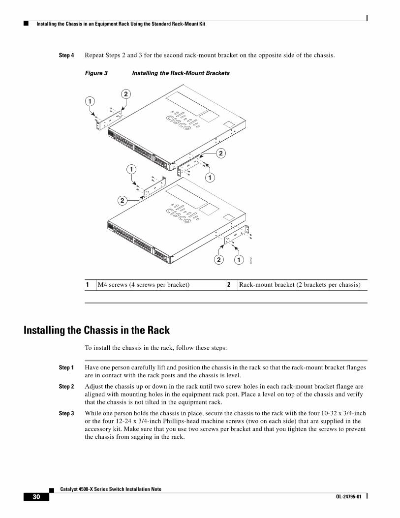
Attaching the Rack-Mount Brackets to the ChassisTo install the rack-mount brackets on the front sides of the chassis, follow these steps:
Step 1 Remove the two rack-mount brackets and eight M4 x 6 mm Phillips flat-head screws from the accessory kit.
Step 2 Position one of the rack-mount brackets against one side of the chassis, and align the four countersunk screw holes with the four M4 holes in the chassis. (See Figure 3.)
Note In Figure 3, the top view shows the rack-mount brackets being attached to the front sides of the chassis. The bottom view shows the rack-mount brackets being attached to the rear sides of the chassis.
Step 3 Secure the rack-mount bracket to the chassis with four M4 x 6 mm Phillips flat-head screws. Make sure that you use all four screws. Using a torque wrench, tighten the four screws to between 8 inch-lbs and 10 inch-lbs (0.90 Newton-meters to 1.13 Newton-meters).
29Catalyst 4500-X Series Switch Installation Note
OL-24795-01
Installing the Chassis in an Equipment Rack Using the Standard Rack-Mount Kit
Step 4 Repeat Steps 2 and 3 for the second rack-mount bracket on the opposite side of the chassis.
Figure 3 Installing the Rack-Mount Brackets
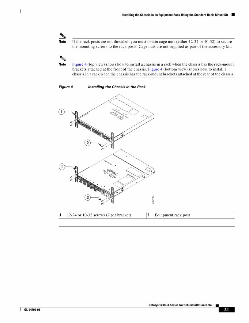
Installing the Chassis in the RackTo install the chassis in the rack, follow these steps:
Step 1 Have one person carefully lift and position the chassis in the rack so that the rack-mount bracket flanges are in contact with the rack posts and the chassis is level.
Step 2 Adjust the chassis up or down in the rack until two screw holes in each rack-mount bracket flange are aligned with mounting holes in the equipment rack post. Place a level on top of the chassis and verify that the chassis is not tilted in the equipment rack.
Step 3 While one person holds the chassis in place, secure the chassis to the rack with the four 10-32 x 3/4-inch or the four 12-24 x 3/4-inch Phillips-head machine screws (two on each side) that are supplied in the accessory kit. Make sure that you use two screws per bracket and that you tighten the screws to prevent the chassis from sagging in the rack.
1 M4 screws (4 screws per bracket) 2 Rack-mount bracket (2 brackets per chassis)
2
3321
91
21
1
2
2
1
1
30Catalyst 4500-X Series Switch Installation Note
OL-24795-01
Installing the Chassis in an Equipment Rack Using the Standard Rack-Mount Kit
Note If the rack posts are not threaded, you must obtain cage nuts (either 12-24 or 10-32) to secure the mounting screws to the rack posts. Cage nuts are not supplied as part of the accessory kit.
Note Figure 4 (top view) shows how to install a chassis in a rack when the chassis has the rack-mount brackets attached at the front of the chassis. Figure 4 (bottom view) shows how to install a chassis in a rack when the chassis has the rack-mount brackets attached at the rear of the chassis.
Figure 4 Installing the Chassis in the Rack
1 12-24 or 10-32 screws (2 per bracket) 2 Equipment rack post
3321
90
1
2
1
2
31Catalyst 4500-X Series Switch Installation Note
OL-24795-01
Installing the Chassis in an Equipment Rack Using the Standard Rack-Mount Kit
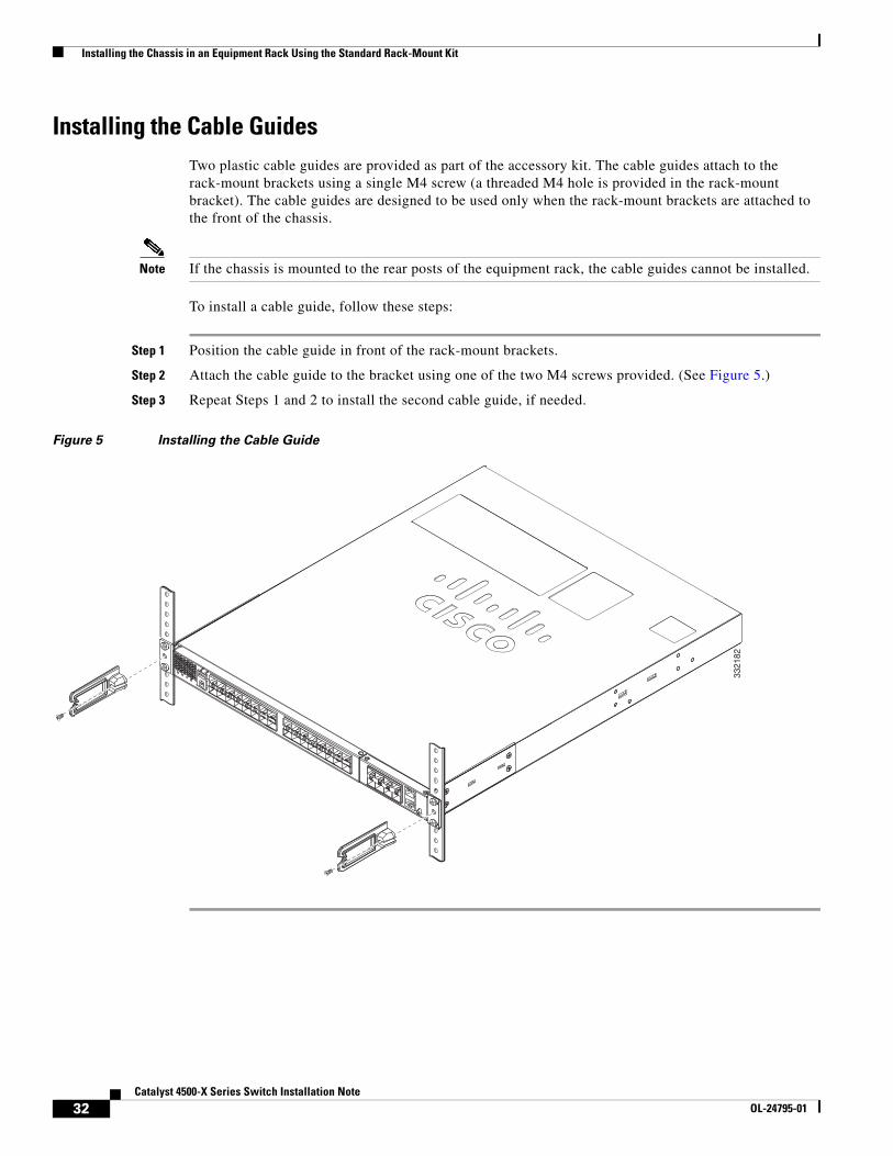
Installing the Cable Guides Two plastic cable guides are provided as part of the accessory kit. The cable guides attach to the rack-mount brackets using a single M4 screw (a threaded M4 hole is provided in the rack-mount bracket). The cable guides are designed to be used only when the rack-mount brackets are attached to the front of the chassis.
Note If the chassis is mounted to the rear posts of the equipment rack, the cable guides cannot be installed.
To install a cable guide, follow these steps:
Step 1 Position the cable guide in front of the rack-mount brackets.
Step 2 Attach the cable guide to the bracket using one of the two M4 screws provided. (See Figure 5.)
Step 3 Repeat Steps 1 and 2 to install the second cable guide, if needed.
Figure 5 Installing the Cable Guide
3321
82
32Catalyst 4500-X Series Switch Installation Note
OL-24795-01
Optional Rack-Mount Kit Installation Instructions
Optional Rack-Mount Kit Installation InstructionsInstallation instructions are provided if you choose to install the Catalyst 4500-X series switch chassis in an equipment rack using one of the three optional rack-mount kits:
• Installing the Chassis Using Either the Optional WS-X4948E-19CNTR= or the Optional WS-X4948E-23CNTR= Center Rack-Mount Kits, page 33
• Installing the Chassis Using the Optional C4948E-BKT-KIT= Rack-Mount Kit, page 37
Installing the Chassis Using Either the Optional WS-X4948E-19CNTR= or the Optional WS-X4948E-23CNTR= Center Rack-Mount Kits
Use these kits when you want to center-rack mount the Catalyst 4500-X series switch chassis in either a 19-inch or a 23-inch rack.
To install either the 19-inch or the 23-inch center rack-mount kit on the Catalyst 4500-X chassis, follow these steps:
Step 1 Place the switch chassis on an antistatic work surface.
Step 2 If the standard rack-mount brackets are attached to the chassis, you must remove them by loosening and removing the eight M4 screws (four on each side) that secure the standard rack-mount brackets to the chassis sides. (See Figure 6.) Set the screws and the brackets aside.
33Catalyst 4500-X Series Switch Installation Note
OL-24795-01
Optional Rack-Mount Kit Installation Instructions
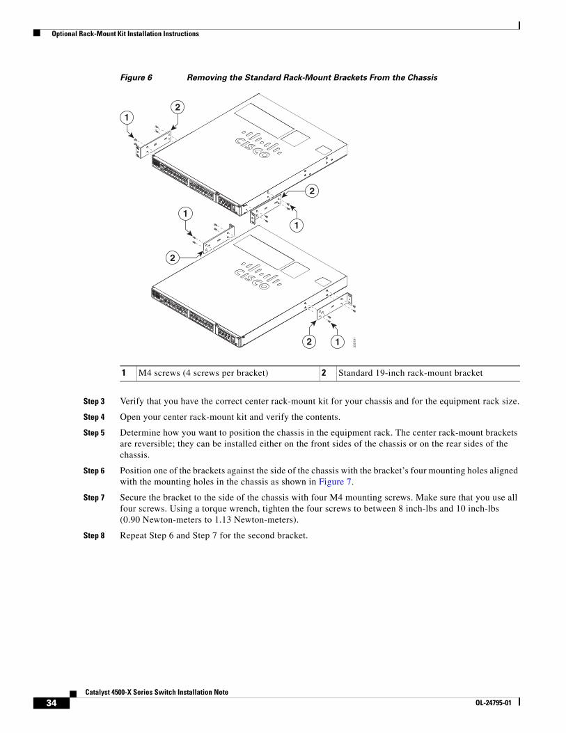
Figure 6 Removing the Standard Rack-Mount Brackets From the Chassis
Step 3 Verify that you have the correct center rack-mount kit for your chassis and for the equipment rack size.
Step 4 Open your center rack-mount kit and verify the contents.
Step 5 Determine how you want to position the chassis in the equipment rack. The center rack-mount brackets are reversible; they can be installed either on the front sides of the chassis or on the rear sides of the chassis.
Step 6 Position one of the brackets against the side of the chassis with the bracket’s four mounting holes aligned with the mounting holes in the chassis as shown in Figure 7.
Step 7 Secure the bracket to the side of the chassis with four M4 mounting screws. Make sure that you use all four screws. Using a torque wrench, tighten the four screws to between 8 inch-lbs and 10 inch-lbs (0.90 Newton-meters to 1.13 Newton-meters).
Step 8 Repeat Step 6 and Step 7 for the second bracket.
1 M4 screws (4 screws per bracket) 2 Standard 19-inch rack-mount bracket
233
2191
21
1
2
2
1
1
34Catalyst 4500-X Series Switch Installation Note
OL-24795-01
Optional Rack-Mount Kit Installation Instructions
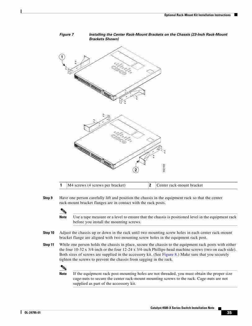
Figure 7 Installing the Center Rack-Mount Brackets on the Chassis (23-Inch Rack-Mount
Brackets Shown)
Step 9 Have one person carefully lift and position the chassis in the equipment rack so that the center rack-mount bracket flanges are in contact with the rack posts.
Note Use a tape measure or a level to ensure that the chassis is positioned level in the equipment rack before you install the mounting screws.
Step 10 Adjust the chassis up or down in the rack until two mounting screw holes in each center rack-mount bracket flange are aligned with two mounting screw holes in the equipment rack post.
Step 11 While one person holds the chassis in place, secure the chassis to the equipment rack posts with either the four 10-32 x 3/4-inch or the four 12-24 x 3/4-inch Phillips-head machine screws (two on each side). Both sizes of screws are supplied in the accessory kit. (See Figure 8.) Make sure that you securely tighten the screws to prevent the chassis from sagging in the rack.
Note If the equipment rack post-mounting holes are not threaded, you must obtain the proper size cage-nuts to secure the center rack-mount mounting screws to the rack. Cage-nuts are not supplied as part of the accessory kit.
1 M4 screws (4 screws per bracket) 2 Center rack-mount bracket
2 3321
83
1
35Catalyst 4500-X Series Switch Installation Note
OL-24795-01
Optional Rack-Mount Kit Installation Instructions
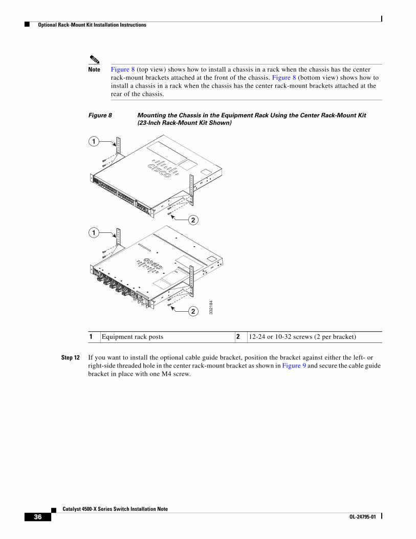
Note Figure 8 (top view) shows how to install a chassis in a rack when the chassis has the center rack-mount brackets attached at the front of the chassis. Figure 8 (bottom view) shows how to install a chassis in a rack when the chassis has the center rack-mount brackets attached at the rear of the chassis.
Figure 8 Mounting the Chassis in the Equipment Rack Using the Center Rack-Mount Kit
(23-Inch Rack-Mount Kit Shown)
Step 12 If you want to install the optional cable guide bracket, position the bracket against either the left- or right-side threaded hole in the center rack-mount bracket as shown in Figure 9 and secure the cable guide bracket in place with one M4 screw.
1 Equipment rack posts 2 12-24 or 10-32 screws (2 per bracket)
3321
84
1
2
1
2
36Catalyst 4500-X Series Switch Installation Note
OL-24795-01
Optional Rack-Mount Kit Installation Instructions
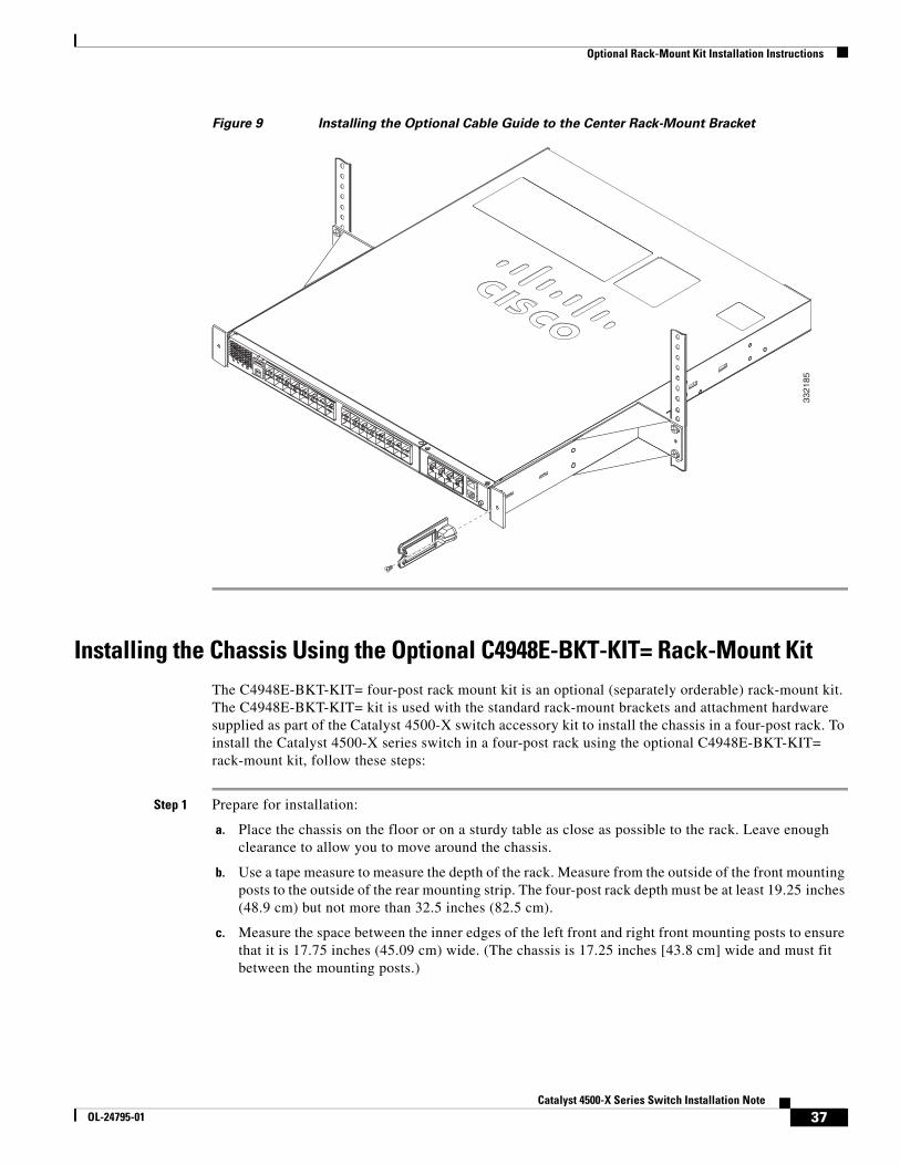
Figure 9 Installing the Optional Cable Guide to the Center Rack-Mount Bracket
Installing the Chassis Using the Optional C4948E-BKT-KIT= Rack-Mount KitThe C4948E-BKT-KIT= four-post rack mount kit is an optional (separately orderable) rack-mount kit. The C4948E-BKT-KIT= kit is used with the standard rack-mount brackets and attachment hardware supplied as part of the Catalyst 4500-X switch accessory kit to install the chassis in a four-post rack. To install the Catalyst 4500-X series switch in a four-post rack using the optional C4948E-BKT-KIT= rack-mount kit, follow these steps:
Step 1 Prepare for installation:
a. Place the chassis on the floor or on a sturdy table as close as possible to the rack. Leave enough clearance to allow you to move around the chassis.
b. Use a tape measure to measure the depth of the rack. Measure from the outside of the front mounting posts to the outside of the rear mounting strip. The four-post rack depth must be at least 19.25 inches (48.9 cm) but not more than 32.5 inches (82.5 cm).
c. Measure the space between the inner edges of the left front and right front mounting posts to ensure that it is 17.75 inches (45.09 cm) wide. (The chassis is 17.25 inches [43.8 cm] wide and must fit between the mounting posts.)
3321
85
37Catalyst 4500-X Series Switch Installation Note
OL-24795-01
Optional Rack-Mount Kit Installation Instructions
Step 2 Verify that the standard rack-mount brackets that ship with the chassis accessory kit are installed on the front sides of the chassis. (See Figure 3, top view.) Using a torque wrench, verify that all eight bracket mounting screws are tightened to between 8 inch-lbs and 10 inch-lbs (0.90 Newton-meters to 1.13 Newton-meters).
Step 3 Open the optional four-post rack-mount kit and remove the four brackets (two chassis attach brackets and two slider brackets) and the mounting hardware.
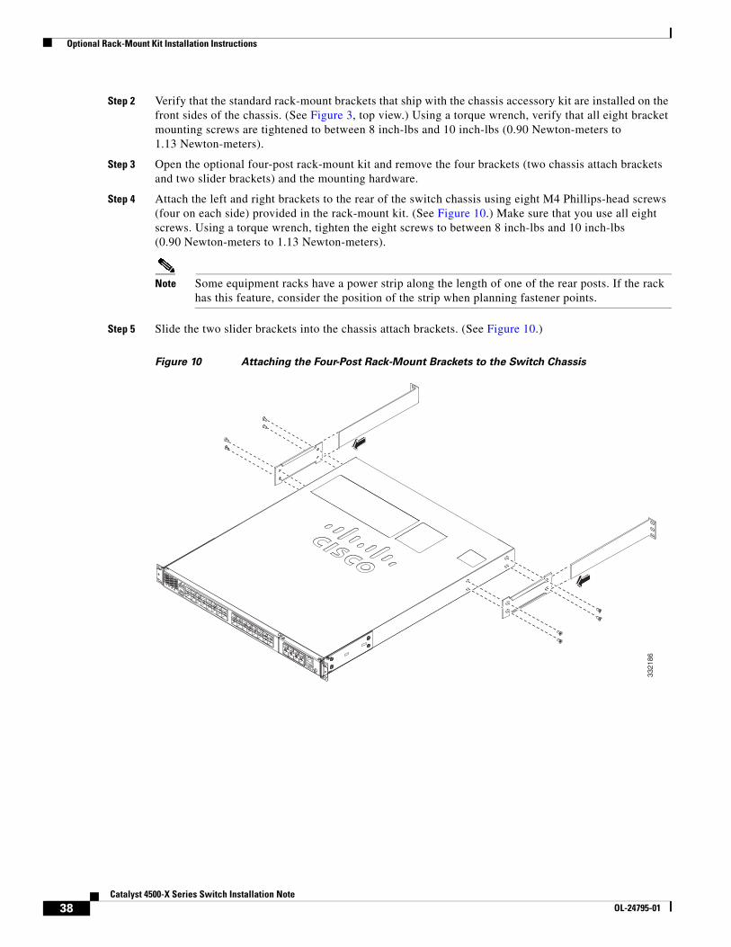
Step 4 Attach the left and right brackets to the rear of the switch chassis using eight M4 Phillips-head screws (four on each side) provided in the rack-mount kit. (See Figure 10.) Make sure that you use all eight screws. Using a torque wrench, tighten the eight screws to between 8 inch-lbs and 10 inch-lbs (0.90 Newton-meters to 1.13 Newton-meters).
Note Some equipment racks have a power strip along the length of one of the rear posts. If the rack has this feature, consider the position of the strip when planning fastener points.
Step 5 Slide the two slider brackets into the chassis attach brackets. (See Figure 10.)
Figure 10 Attaching the Four-Post Rack-Mount Brackets to the Switch Chassis
3321
86
38Catalyst 4500-X Series Switch Installation Note
OL-24795-01
Optional Rack-Mount Kit Installation Instructions
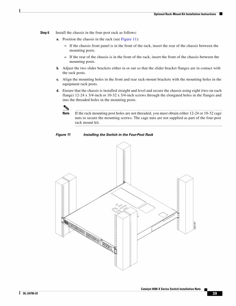
Step 6 Install the chassis in the four-post rack as follows:
a. Position the chassis in the rack (see Figure 11):
– If the chassis front panel is in the front of the rack, insert the rear of the chassis between the mounting posts.
– If the rear of the chassis is in the front of the rack, insert the front of the chassis between the mounting posts.
b. Adjust the two slider brackets either in or out so that the slider bracket flanges are in contact with the rack posts.
c. Align the mounting holes in the front and rear rack-mount brackets with the mounting holes in the equipment rack posts.
d. Ensure that the chassis is installed straight and level and secure the chassis using eight (two on each flange) 12-24 x 3/4-inch or 10-32 x 3/4-inch screws through the elongated holes in the flanges and into the threaded holes in the mounting posts.
Note If the rack mounting post holes are not threaded, you must obtain either 12-24 or 10-32 cage nuts to secure the mounting screws. The cage nuts are not supplied as part of the four-post rack mount kit.
Figure 11 Installing the Switch in the Four-Post Rack
3321
87
39Catalyst 4500-X Series Switch Installation Note
OL-24795-01
Optional Rack-Mount Kit Installation Instructions
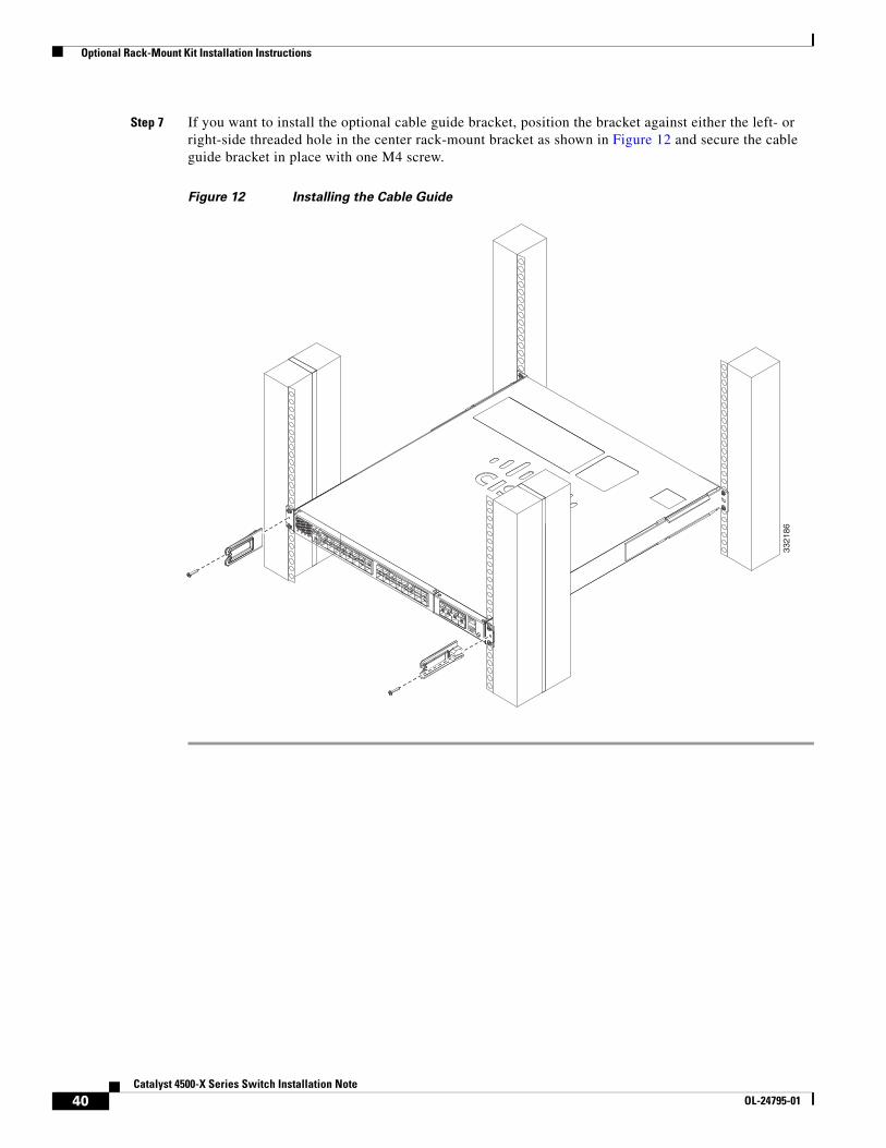
Step 7 If you want to install the optional cable guide bracket, position the bracket against either the left- or right-side threaded hole in the center rack-mount bracket as shown in Figure 12 and secure the cable guide bracket in place with one M4 screw.
Figure 12 Installing the Cable Guide
3321
86
40Catalyst 4500-X Series Switch Installation Note
OL-24795-01
Attaching System Ground
Attaching System GroundThe system (NEBS) ground provides additional grounding for EMI shielding requirements and is intended to satisfy the Telcordia Technologies NEBS requirements for supplemental bonding and grounding connections.
To connect the system ground, you need the following tools and materials:
• Ground lug kit—Supplied as part of the Catalyst 4500-X series accessory kit. The ground lug kit contains:
– Ground lug—A two-hole standard 90-degree barrel lug. The lug supports up to 6 AWG wire.
– Ground lug screws—Two M4 x 8 mm pan-head screws.
• Ground wire—The system ground wire should be sized according to local and national installation requirements. We recommend that you use commercially available 6 AWG wire. The length of the system ground wire depends on the proximity of the switch to proper grounding facilities. The ground wire is not provided as part of the accessory kit.
• No. 1 Phillips screwdriver.
• Wire-stripping tool to remove the insulation from the ground wire.
• Crimping tool to crimp the system ground wire to the ground lug.
To attach the system ground wire to the ground lug and attach the lug to the grounding pad, follow these steps:
Step 1 If you are using insulated wire, use a wire-stripping tool to remove approximately 0.75 inch (19 mm) of the covering from the end of the ground wire. If you are using bare wire, go to Step 2.
Step 2 Insert the stripped end of the ground wire into the open end of the ground lug.
Step 3 Crimp the ground wire in the barrel of the ground lug. Gently tug on the ground wire to verify that it is securely attached to the ground lug.
Step 4 Place the ground wire lug against the system ground pad located on the rear panel of the chassis (see Figure 2), making sure that there is solid metal-to-metal contact.
Step 5 Secure the ground lug to the chassis with the two M4 screws supplied in the accessory kit. (See Figure 13.) Route the system ground wire to ensure that it does not interfere with other switch hardware or rack equipment.
Step 6 Prepare the other end of the ground wire and connect it to an appropriate earth ground point in your site to ensure adequate earth ground for the switch.
41Catalyst 4500-X Series Switch Installation Note
OL-24795-01
Installing the Interface Cables
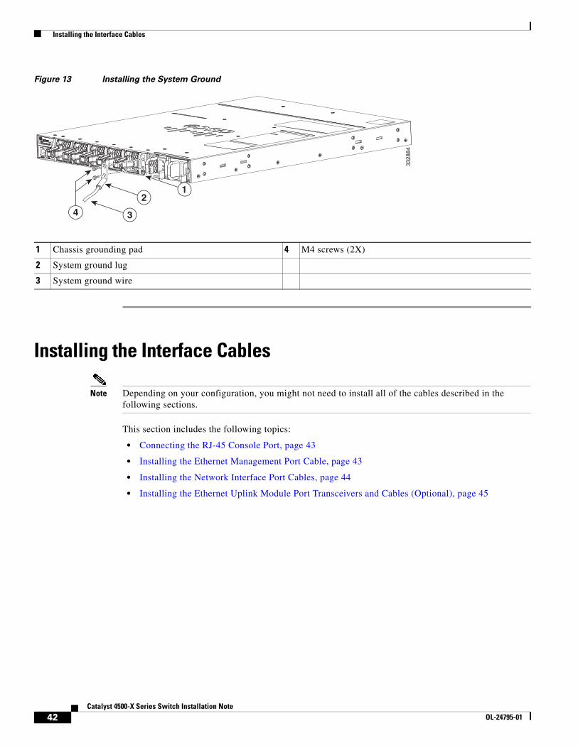
Figure 13 Installing the System Ground
Installing the Interface Cables
Note Depending on your configuration, you might not need to install all of the cables described in the following sections.
This section includes the following topics:
• Connecting the RJ-45 Console Port, page 43
• Installing the Ethernet Management Port Cable, page 43
• Installing the Network Interface Port Cables, page 44
• Installing the Ethernet Uplink Module Port Transceivers and Cables (Optional), page 45
1 Chassis grounding pad 4 M4 screws (2X)
2 System ground lug
3 System ground wire
3328
84
4
12
3
42Catalyst 4500-X Series Switch Installation Note
OL-24795-01
Installing the Interface Cables
Connecting the RJ-45 Console PortThe RJ-45 console port is located on the rear panel of the switch.
Note A console port cable is not provided as part of the accessory kit. The cable (part no. CAB-CON-C4K-RJ45) can be ordered as an option.
To connect the RJ-45 console port, follow these steps:
Step 1 Connect an RJ-45-to-DB-9 adapter cable to the 9-pin serial port on the PC. Connect the other end of the cable to the switch console port.
Step 2 Start the terminal emulation program on the PC or the terminal. The program, frequently a PC application, such as HyperTerminal or ProcommPlus, makes communication between the switch and your PC or terminal possible.
Step 3 Configure the baud rate and character format of the PC or terminal to match the console port characteristics:
• 9600 baud
• 8 data bits
• 1 stop bit
• No parity
• None (flow control)
Step 4 The PC or terminal displays the bootloader sequence. Press Enter to display the setup prompt. Follow the steps in the “Configuring the Setup Program” section on page 47.
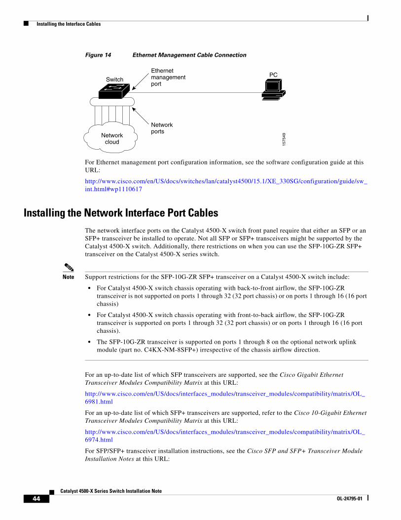
Installing the Ethernet Management Port CableThe Ethernet management port provides out-of-band management, which enables you to use the CLI interface to manage the switch by its IP address. This port uses a 10/100/1000 Ethernet connection with an RJ-45 interface. Figure 14 shows a typical Ethernet management connection between the switch and a PC.
The typical connection to the Management Ethernet port uses an Ethernet cable with RJ-45 connectors at each end. To attach a cable to the Ethernet management port, follow these steps:
Step 1 Connect the RJ-45 plug at one end of the network cable to the target device port.
Step 2 Connect the RJ-45 plug at the other end of the network cable to the Ethernet Management port on the Catalyst 4500-X chassis.
43Catalyst 4500-X Series Switch Installation Note
OL-24795-01
Installing the Interface Cables
Figure 14 Ethernet Management Cable Connection
For Ethernet management port configuration information, see the software configuration guide at this URL:
http://www.cisco.com/en/US/docs/switches/lan/catalyst4500/15.1/XE_330SG/configuration/guide/sw_int.html#wp1110617
Installing the Network Interface Port CablesThe network interface ports on the Catalyst 4500-X switch front panel require that either an SFP or an SFP+ transceiver be installed to operate. Not all SFP or SFP+ transceivers might be supported by the Catalyst 4500-X switch. Additionally, there restrictions on when you can use the SFP-10G-ZR SFP+ transceiver on the Catalyst 4500-X series switch.
Note Support restrictions for the SFP-10G-ZR SFP+ transceiver on a Catalyst 4500-X switch include:
• For Catalyst 4500-X switch chassis operating with back-to-front airflow, the SFP-10G-ZR transceiver is not supported on ports 1 through 32 (32 port chassis) or on ports 1 through 16 (16 port chassis)
• For Catalyst 4500-X switch chassis operating with front-to-back airflow, the SFP-10G-ZR transceiver is supported on ports 1 through 32 (32 port chassis) or on ports 1 through 16 (16 port chassis).
• The SFP-10G-ZR transceiver is supported on ports 1 through 8 on the optional network uplink module (part no. C4KX-NM-8SFP+) irrespective of the chassis airflow direction.
For an up-to-date list of which SFP transceivers are supported, see the Cisco Gigabit Ethernet Transceiver Modules Compatibility Matrix at this URL:
http://www.cisco.com/en/US/docs/interfaces_modules/transceiver_modules/compatibility/matrix/OL_6981.html
For an up-to-date list of which SFP+ transceivers are supported, refer to the Cisco 10-Gigabit Ethernet Transceiver Modules Compatibility Matrix at this URL:
http://www.cisco.com/en/US/docs/interfaces_modules/transceiver_modules/compatibility/matrix/OL_6974.html
For SFP/SFP+ transceiver installation instructions, see the Cisco SFP and SFP+ Transceiver Module Installation Notes at this URL:
1575
49
SwitchPC
Networkcloud
Ethernetmanagementport
Networkports
44Catalyst 4500-X Series Switch Installation Note
OL-24795-01
Attaching the AC-Input Power Supply Power Cord
http://www.cisco.com/en/US/docs/interfaces_modules/transceiver_modules/installation/note/78_15160.html
Installing the Ethernet Uplink Module Port Transceivers and Cables (Optional)When installed in the Catalyst 4500-X switch chassis, the optional 8-port Ethernet uplink module (C4KX-NM-8SFP+) requires either SFP (1000BASE-X) or SFP+ (10GBASE-X) transceiver modules to operate. For an up-to-date list of which SFP transceivers are supported, see the Cisco Gigabit Ethernet Transceiver Modules Compatibility Matrix at this URL:
http://www.cisco.com/en/US/docs/interfaces_modules/transceiver_modules/compatibility/matrix/OL_6981.html
For an up-to-date list of which SFP+ transceivers are supported, refer to the Cisco 10-Gigabit Ethernet Transceiver Modules Compatibility Matrix at this URL:
http://www.cisco.com/en/US/docs/interfaces_modules/transceiver_modules/compatibility/matrix/OL_6974.html
For SFP and SFP+ transceiver installation instructions, see the Cisco SFP and SFP+ Transceiver Modules Installation Notes at this URL:
http://www.cisco.com/en/US/docs/interfaces_modules/transceiver_modules/installation/note/78_15160.html
Attaching the AC-Input Power Supply Power CordThe Catalyst 4500-X series switch supports the following combinations of power supplies:
• One or two AC-input power supplies
• One or two DC-input power supplies
• One AC-input power supply and one DC-input power supply
Note The AC-input power supply is not supplied as part of the standard chassis configuration. Power supplies must be ordered separately.
The Catalyst 4500-X switch chassis supports either one or two AC-input power supplies in bays located at the back of the chassis. (See Figure 2.) Use the appropriate AC power cord to connect your chassis AC-input power supply to source AC. See the Catalyst 4500-X AC-Input Power Supply Installation Note for a list and descriptions of the AC power cords supported by the Catalyst 4500-X switch AC-input power supply.
In chassis equipped with redundant power supplies, it is recommended that you connect the power supplies to separate source AC circuits to prevent the chassis from shutting down in the event that one source AC circuit fails.
Note The AC-input power supply does not have a power switch. Once the power cord is connected between the AC-input power supply and source AC and source AC is on, the power supply immediately powers up.
45Catalyst 4500-X Series Switch Installation Note
OL-24795-01
Attaching the DC-Input Power Supply Power Cable
Attaching the DC-Input Power Supply Power CableThe Catalyst 4500-X series switch supports either one or two DC-input power supplies in bays at the back of the chassis. (See Figure 2.) Procedures for cabling source DC to the DC-input power supply are contained in the Catalyst 4500-X DC-Input Power Supply Installation Note.
Note The DC-input power supply is not supplied as part of the standard chassis configuration. Power supplies must be ordered separately.
Note The DC-input power supply does not have a power switch. Once the cabling is complete between the power supply and source DC and the source DC breaker is turned on, the power supply immediately powers up.
Monitoring the LEDsThe Catalyst 4500-X series switch has a complement of LEDs that provide the status of the chassis components as the system powers up. As the chassis powers up, you can monitor the progress by watching the LEDs located on the front panel of the chassis, the front panel of the fan tray (located at the back of the chassis), and the front panel of the power supplies (located at the back of the chassis) as follows:
• STATUS LED cycles from flashing green to amber to green
• Power supply LEDs (PS1/PS2) cycles from amber to green
• FAN LED cycles from amber to green
Once the chassis has completed the power up cycle (STATUS LED is green), you are ready to perform a configuration of the chassis. See the Software Configuration Guide for detailed procedures on how to configure your system.
46Catalyst 4500-X Series Switch Installation Note
OL-24795-01
Entering the Initial Configuration Information
Entering the Initial Configuration InformationTo set up the switch, you need to complete the setup program, which runs automatically after the switch is powered on. You must assign an IP address and other configuration information necessary for the switch to communicate with the local routers and the Internet. This information is also needed to use the device manager or Cisco Network Assistant to configure and manage the switch.
IP SettingsYou need this information from your network administrator:
• Switch IP address
• Subnet mask (IP netmask)
• Default gateway (router)
• Enable secret password
• Enable password
• Telnet password
Configuring the Setup ProgramTo complete the setup program and an initial configuration for the switch, follow these steps:
Step 1 Enter Yes at the following two prompts.
Would you like to enter the initial configuration dialog? [yes/no]: yes
At any point you may enter a question mark '?' for help.Use ctrl-c to abort configuration dialog at any prompt.Default settings are in square brackets '[]'.
Basic management setup configures only enough connectivityfor management of the system, extended setup will ask youto configure each interface on the system.
Would you like to enter basic management setup? [yes/no]: yes
Step 2 Enter a hostname for the switch, and press Return.
On a command switch, the host name is limited to 28 characters and on a member switch it is limited to 31 characters. Do not use -n, where n is a number, as the last character in a hostname for any switch.
Enter host name [Switch]: host_name
Step 3 Enter an enable secret password, and press Return.
The password can be from 1 to 25 alphanumeric characters, can start with a number, is case sensitive, allows spaces, but ignores leading spaces. The secret password is encrypted, and the enable password is in plain text.
Enter enable secret: secret_password
47Catalyst 4500-X Series Switch Installation Note
OL-24795-01
Entering the Initial Configuration Information
Step 4 Enter an enable password, and press Return.
Enter enable password: enable_password
Step 5 Enter a virtual terminal (Telnet) password, and press Return.
The password can be from 1 to 25 alphanumeric characters, is case sensitive, allows spaces, but ignores leading spaces.
Enter virtual terminal password: terminal-password
Step 6 (Optional) Configure the Simple Network Management Protocol (SNMP) by responding to the prompts. You can also configure SNMP later through the CLI, the device manager, or the Network Assistant application. To configure SNMP later, enter no.
Configure SNMP Network Management? [no]: no
Step 7 Enter the interface name (physical interface or VLAN name) of the interface that connects to the management network, and press Return. For this release, always use vlan1 as that interface.
Enter interface name used to connect to themanagement network from the above interface summary: vlan1
Step 8 Configure the interface by entering the switch IP address and subnet mask and pressing Return. The IP address and subnet masks shown are examples.
Configuring interface vlan1:Configure IP on this interface? [yes]: yes IP address for this interface: 10.4.120.106Subnet mask for this interface [255.0.0.0]: 255.0.0.0
Step 9 Enter Y to configure the switch as the cluster command switch. Enter N to configure it as a member switch or as a standalone switch.
If you enter N, the switch appears as a candidate switch in the Network Assistant GUI. You can configure the switch as a command switch later through the CLI, the device manager, or the Network Assistant application. To configure it later, enter no.
Would you like to enable as a cluster command switch? [yes/no]: no
You have completed the initial configuration of the switch, and the switch displays its configuration. This is an example of the configuration output:
The following configuration command script was created:hostname switch1enable secret 5 $1$Ulq8$DlA/OiaEbl90WcBPd9cOn1enable password enable_passwordline vty 0 15password terminal-passwordno snmp-server!no ip routing
!interface Vlan1no shutdown
48Catalyst 4500-X Series Switch Installation Note
OL-24795-01
Entering the Initial Configuration Information
ip address 10.4.120.106 255.0.0.0!interface GigabitEthernet1/0/1!interface GigabitEthernet1/0/2
interface GigabitEthernet1/0/3!...<output abbreviated>!
interface GigabitEthernet1/0/23!end
These choices appear:
[0] Go to the IOS command prompt without saving this config.
[1] Return back to the setup without saving this config.
[2] Save this configuration to nvram and exit.
Step 10 If you want to save the configuration and use it the next time that the switch reboots, select option 2 to save it in nonvolatile RAM (NVRAM).
Enter your selection [2]:2
Make your selection, and press Return.
After you complete the setup program, the switch can run the default configuration that you created. To change this configuration or to perform other management tasks, enter commands at the Switch> prompt or use Cisco Network Assistant.
49Catalyst 4500-X Series Switch Installation Note
OL-24795-01
Related Documentation
Related DocumentationTable 8 lists the documentation supporting the Catalyst 4500-X series switch that is available on http://www.cisco.com.
Obtaining Documentation and Submitting a Service RequestFor information on obtaining documentation, submitting a service request, and gathering additional information, see the monthly What’s New in Cisco Product Documentation, which also lists all new and revised Cisco technical documentation, at:
http://www.cisco.com/en/US/docs/general/whatsnew/whatsnew.html
Subscribe to the What’s New in Cisco Product Documentation as an RSS feed and set content to be delivered directly to your desktop using a reader application. The RSS feeds are a free service. Cisco currently supports RSS Version 2.0.
Table 8 Documentation Supporting the Catalyst 4500-X Series Switch
Title Description of Contents
Catalyst 4500-X 8-Port Network Uplink Module Installation Note
Contains instructions for installing and removing the optional 8-port network uplink module in the Catalyst 4500-X chassis.
Catalyst 4500-X AC-Input Power Supply Installation Note
Contains instructions for removing and installing the AC-input power supply in the Catalyst 4500-X switch chassis. Also contains descriptions of the supported AC power cords.
Catalyst 4500-X DC-Input Power Supply Installation Note
Contains instructions for removing and installing the DC-input power supply in the Catalyst 4500-X switch chassis.
Catalyst 4500-X Fan Assembly Installation Note
Contains instructions for removing and installing a fan assembly in the Catalyst 4500-X switch chassis.
Regulatory Compliance and Safety Information for the Catalyst 4500-X Series Switch
Contains the regulatory compliance and safety information for the Catalyst 4500-X series switch chassis. Also includes language translations of the warnings that appear in the other Catalyst 4500-X documentation.
Catalyst 4500 Series Switch Cisco IOS Software Configuration Guide, Release IOS XE 3.3.0SG(15.1(1)SG)
Contains instructions on how to configure the Catalyst 4500-X switch.
Catalyst 4500 Series Switch Cisco IOS Command Reference, Release IOS XE 3.3.0SG(15.1(1)SG)
Contains descriptions of all of the software commands available that support the Catalyst 4500-X switch.
Release Notes for the Catalyst 4500 Series Switch, Release IOS XE 3.3.0SG(15.1(1)SG)
Contains the latest software caveats and workarounds related to the Catalyst 4500-X switch.
50Catalyst 4500-X Series Switch Installation Note
OL-24795-01

Obtaining Documentation and Submitting a Service Request
This document is to be used in conjunction with the documents listed in the related documents section.
Cisco and the Cisco logo are trademarks or registered trademarks of Cisco and/or its affiliates in the U.S. and other countries. To view a list of Cisco trademarks, go to this URL: www.cisco.com/go/trademarks. Third-party trademarks mentioned are the property of their respective owners. The use of the word partner does not imply a partnership relationship between Cisco and any other company. (1110R)
Any Internet Protocol (IP) addresses and phone numbers used in this document are not intended to be actual addresses and phone numbers. Any examples, command display output, network topology diagrams, and other figures included in the document are shown for illustrative purposes only. Any use of actual IP addresses or phone numbers in illustrative content is unintentional and coincidental.
© 2012 Cisco Systems, Inc. All rights reserved.
51Catalyst 4500-X Series Switch Installation Note
OL-24795-01

Obtaining Documentation and Submitting a Service Request
52Catalyst 4500-X Series Switch Installation Note
OL-24795-01