Embed Size (px)
Citation preview
Catalyst 3850 Switch Hardware Installation GuideFirst Published: January 21, 2013
Last Modified: August 21, 2014
Americas HeadquartersCisco Systems, Inc.170 West Tasman DriveSan Jose, CA 95134-1706USAhttp://www.cisco.comTel: 408 526-4000 800 553-NETS (6387)Fax: 408 527-0883
Text Part Number: OL-26779-04
THE SPECIFICATIONS AND INFORMATION REGARDING THE PRODUCTS IN THIS MANUAL ARE SUBJECT TO CHANGE WITHOUT NOTICE. ALL STATEMENTS,INFORMATION, AND RECOMMENDATIONS IN THIS MANUAL ARE BELIEVED TO BE ACCURATE BUT ARE PRESENTED WITHOUT WARRANTY OF ANY KIND,EXPRESS OR IMPLIED. USERS MUST TAKE FULL RESPONSIBILITY FOR THEIR APPLICATION OF ANY PRODUCTS.
THE SOFTWARE LICENSE AND LIMITEDWARRANTY FOR THE ACCOMPANYING PRODUCT ARE SET FORTH IN THE INFORMATION PACKET THAT SHIPPED WITHTHE PRODUCT AND ARE INCORPORATED HEREIN BY THIS REFERENCE. IF YOU ARE UNABLE TO LOCATE THE SOFTWARE LICENSE OR LIMITED WARRANTY,CONTACT YOUR CISCO REPRESENTATIVE FOR A COPY.
The following information is for FCC compliance of Class A devices: This equipment has been tested and found to comply with the limits for a Class A digital device, pursuant to part 15of the FCC rules. These limits are designed to provide reasonable protection against harmful interference when the equipment is operated in a commercial environment. This equipmentgenerates, uses, and can radiate radio-frequency energy and, if not installed and used in accordance with the instruction manual, may cause harmful interference to radio communications.Operation of this equipment in a residential area is likely to cause harmful interference, in which case users will be required to correct the interference at their own expense.
The following information is for FCC compliance of Class B devices: This equipment has been tested and found to comply with the limits for a Class B digital device, pursuant to part 15of the FCC rules. These limits are designed to provide reasonable protection against harmful interference in a residential installation. This equipment generates, uses and can radiate radiofrequency energy and, if not installed and used in accordance with the instructions, may cause harmful interference to radio communications. However, there is no guarantee that interferencewill not occur in a particular installation. If the equipment causes interference to radio or television reception, which can be determined by turning the equipment off and on, users areencouraged to try to correct the interference by using one or more of the following measures:
• Reorient or relocate the receiving antenna.
• Increase the separation between the equipment and receiver.
• Connect the equipment into an outlet on a circuit different from that to which the receiver is connected.
• Consult the dealer or an experienced radio/TV technician for help.
Modifications to this product not authorized by Cisco could void the FCC approval and negate your authority to operate the product
The Cisco implementation of TCP header compression is an adaptation of a program developed by the University of California, Berkeley (UCB) as part of UCB’s public domain versionof the UNIX operating system. All rights reserved. Copyright © 1981, Regents of the University of California.
NOTWITHSTANDINGANYOTHERWARRANTYHEREIN, ALL DOCUMENT FILES AND SOFTWAREOF THESE SUPPLIERS ARE PROVIDED "AS IS"WITHALL FAULTS.CISCO AND THE ABOVE-NAMED SUPPLIERS DISCLAIM ALL WARRANTIES, EXPRESSED OR IMPLIED, INCLUDING, WITHOUT LIMITATION, THOSE OFMERCHANTABILITY, FITNESS FORA PARTICULAR PURPOSEANDNONINFRINGEMENTORARISING FROMACOURSEOFDEALING, USAGE, OR TRADE PRACTICE.
IN NO EVENT SHALL CISCO OR ITS SUPPLIERS BE LIABLE FOR ANY INDIRECT, SPECIAL, CONSEQUENTIAL, OR INCIDENTAL DAMAGES, INCLUDING, WITHOUTLIMITATION, LOST PROFITS OR LOSS OR DAMAGE TO DATA ARISING OUT OF THE USE OR INABILITY TO USE THIS MANUAL, EVEN IF CISCO OR ITS SUPPLIERSHAVE BEEN ADVISED OF THE POSSIBILITY OF SUCH DAMAGES.
Any Internet Protocol (IP) addresses and phone numbers used in this document are not intended to be actual addresses and phone numbers. Any examples, command display output, networktopology diagrams, and other figures included in the document are shown for illustrative purposes only. Any use of actual IP addresses or phone numbers in illustrative content is unintentionaland coincidental.
Cisco and the Cisco logo are trademarks or registered trademarks of Cisco and/or its affiliates in the U.S. and other countries. To view a list of Cisco trademarks, go to this URL: http://www.cisco.com/go/trademarks. Third-party trademarks mentioned are the property of their respective owners. The use of the word partner does not imply a partnershiprelationship between Cisco and any other company. (1110R)
© 2013, 2014 Cisco Systems, Inc. All rights reserved.
C O N T E N T S
P r e f a c e Preface ix
Document Conventions ix
Related Documentation xi
Obtaining Documentation and Submitting a Service Request xi
C H A P T E R 1 Product Overview 1
Switch Models 1
Front Panel 3
10/100/1000 Ports 5
PoE, PoE+, and Cisco UPOE Ports 5
SFP Module Slots 5
Management Ports 6
USB Type A Port 6
Network Modules 7
SFP and SFP+ Modules 7
LEDs 8
SYST LED 10
XPS LED 10
Port LEDs and Modes 11
USB Console LED 13
S-PWR LED 14
ACTV LED 14
STACK LED 14
PoE LED 15
UID/Beacon LED 16
Network Module LEDs 16
Rear Panel 17
Catalyst 3850 Switch Hardware Installation Guide OL-26779-04 iii
RJ-45 Console Port LED 18
StackWise Ports 19
Power Supply Modules 19
Fan Module 22
StackPower Connector 23
Management Ports 23
Ethernet Management Port 23
RJ-45 Console Port 23
Management Options 24
C H A P T E R 2 Switch Installation 25
Preparing for Installation 25
Safety Warnings 25
Installation Guidelines 27
Box Contents 28
Tools and Equipment 28
Verifying Switch Operation 28
Powering Off the Switch 28
Planning a Switch Data Stack 28
Switch Stacking and Power Stacking Guidelines 28
Data Stack Cabling Configurations 29
Data Stack Bandwidth and Partitioning Examples 30
Power-On Sequence for Switch Stacks 31
Planning a StackPower Stack 32
StackPower Stacking Guidelines 32
StackPower Cabling Configurations 33
StackPower Partitioning Examples 34
Installing the Switch 35
Rack-Mounting 35
Attaching the Rack-Mount Brackets 37
Mounting the Switch a Rack 38
Installing the Switch on a Table or Shelf 38
After Switch Installation 38
Connecting to the StackWise Ports 39
Connecting to the StackPower Ports 41
Catalyst 3850 Switch Hardware Installation Guideiv OL-26779-04
Contents
Installing a Network Module in the Switch 41
Installing and Removing SFP and SFP+ Modules 42
Connecting Devices to the Ethernet Ports 42
10/100/1000 Port Connections 42
Auto-MDIX Connections 42
PoE+ and Cisco UPOE Port Connections 43
Where to Go Next 44
C H A P T E R 3 Installing a Network Module 45
Network Module Overview 45
Network Module LEDs 48
Installing a Network Module in the Switch 49
Safety Warnings 49
Equipment That You Need 49
Installing Network Modules 50
Network Module Port Configurations 51
Removing a Network Module 53
SFP and SFP+ Modules 54
Installing SFP and SFP+ Modules 54
Removing SFP and SFP+ Modules 55
Finding the Network Module Serial Number 56
C H A P T E R 4 Power Supply Installation 57
Power Supply Module Overview 57
Installation Guidelines 61
Installing or Replacing an AC Power Supply 62
Installing a DC Power Supply 63
Equipment That You Need 64
Grounding the Switch 64
Installing the DC Power Supply in the Switch 67
Wiring the DC Input Power Source 67
Finding the Power Supply Module Serial Number 69
C H A P T E R 5 Installing the Fan 71
Fan Module Overview 71
Catalyst 3850 Switch Hardware Installation Guide OL-26779-04 v
Contents
Installation Guidelines 72
Installing a Fan Module 73
Finding the Fan Module Serial Number 74
C H A P T E R 6 Troubleshooting 75
Diagnosing Problems 75
Switch POST Results 75
Switch LEDs 75
Switch Connections 75
Bad or Damaged Cable 75
Ethernet and Fiber-Optic Cables 76
Link Status 76
10/100/1000 Port Connections 76
10/100/1000 PoE+ Port Connections 77
SFP and SFP+ Module 77
Interface Settings 77
Ping End Device 78
Spanning Tree Loops 78
Switch Performance 78
Speed, Duplex, and Autonegotiation 78
Autonegotiation and Network Interface Cards 78
Cabling Distance 79
Clearing the Switch IP Address and Configuration 79
Replacing a Failed Data Stack Member 79
A P P E N D I X A Technical Specifications 81
Environmental and Physical Specifications 81
Specifications for the Power Supplies, Switches, and Fan 83
A P P E N D I X B Connector and Cable Specifications 87
Connector Specifications 87
10/100/1000 Ports (Including PoE) 87
SFP Module Connectors 88
Console Port 89
Cables and Adapters 89
Catalyst 3850 Switch Hardware Installation Guidevi OL-26779-04
Contents
StackWise Cables 89
SFP Module Cables 90
Cable Pinouts 91
Console Port Adapter Pinouts 92
A P P E N D I X C Configuring the Switch with the CLI-Based Setup Program 95
Accessing the CLI Through Express Setup 95
Accessing the CLI Through the Console Port 95
Connecting the RJ-45 Console Port 96
Connecting the USB Console Port 97
Installing the Cisco Microsoft Windows USB Device Driver 98
Installing the Cisco Microsoft Windows XP USB Driver 98
Installing the Cisco Microsoft Windows 2000 USB Driver 98
Installing the Cisco Microsoft Windows Vista and Windows 7 USB Driver 99
Uninstalling the Cisco Microsoft Windows USB Driver 99
Uninstalling the Cisco Microsoft Windows XP and 2000 USB Driver 99
Using the Setup.exe Program 99
Using the Add or Remove Programs Utility 100
Uninstalling the Cisco Microsoft Windows Vista and Windows 7 USB Driver 100
Entering the Initial Configuration Information 101
IP Settings 101
Completing the Setup Program 101
Catalyst 3850 Switch Hardware Installation Guide OL-26779-04 vii
Contents

Catalyst 3850 Switch Hardware Installation Guideviii OL-26779-04
Contents
Preface
• Document Conventions, page ix
• Related Documentation, page xi
• Obtaining Documentation and Submitting a Service Request, page xi
Document ConventionsThis document uses the following conventions:
DescriptionConvention
Both the ^ symbol and Ctrl represent the Control (Ctrl) key on a keyboard. Forexample, the key combination^D orCtrl-Dmeans that you hold down the Controlkey while you press the D key. (Keys are indicated in capital letters but are notcase sensitive.)
^ or Ctrl
Commands and keywords and user-entered text appear in bold font.bold font
Document titles, new or emphasized terms, and arguments for which you supplyvalues are in italic font.
Italic font
Terminal sessions and information the system displays appear in courier font.Courier font
Bold Courier font indicates text that the user must enter.Bold Courier font
Elements in square brackets are optional.[x]
An ellipsis (three consecutive nonbolded periods without spaces) after a syntaxelement indicates that the element can be repeated.
...
A vertical line, called a pipe, indicates a choice within a set of keywords orarguments.
|
Optional alternative keywords are grouped in brackets and separated by verticalbars.
[x | y]
Catalyst 3850 Switch Hardware Installation Guide OL-26779-04 ix
DescriptionConvention
Required alternative keywords are grouped in braces and separated by verticalbars.
{x | y}
Nested set of square brackets or braces indicate optional or required choiceswithin optional or required elements. Braces and a vertical bar within squarebrackets indicate a required choice within an optional element.
[x {y | z}]
A nonquoted set of characters. Do not use quotation marks around the string orthe string will include the quotation marks.
string
Nonprinting characters such as passwords are in angle brackets.< >
Default responses to system prompts are in square brackets.[ ]
An exclamation point (!) or a pound sign (#) at the beginning of a line of codeindicates a comment line.
!, #
Reader Alert Conventions
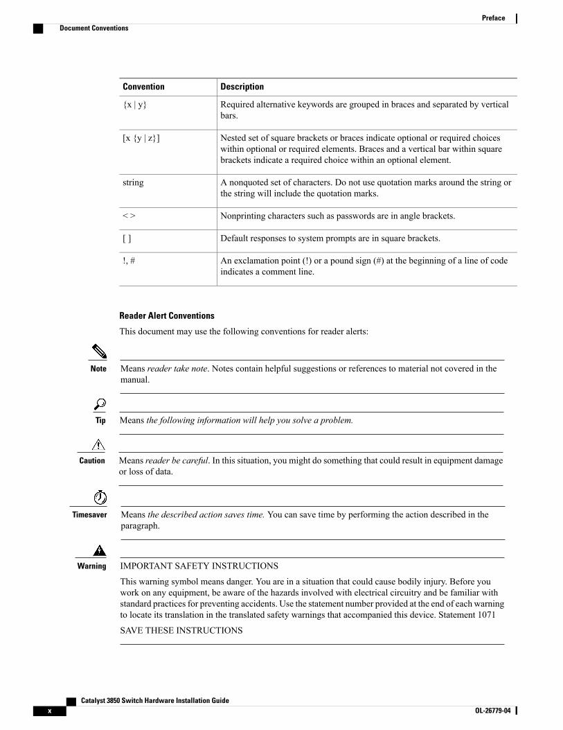
This document may use the following conventions for reader alerts:
Means reader take note. Notes contain helpful suggestions or references to material not covered in themanual.
Note
Means the following information will help you solve a problem.Tip
Means reader be careful. In this situation, you might do something that could result in equipment damageor loss of data.
Caution
Means the described action saves time. You can save time by performing the action described in theparagraph.
Timesaver
IMPORTANT SAFETY INSTRUCTIONS
This warning symbol means danger. You are in a situation that could cause bodily injury. Before youwork on any equipment, be aware of the hazards involved with electrical circuitry and be familiar withstandard practices for preventing accidents. Use the statement number provided at the end of each warningto locate its translation in the translated safety warnings that accompanied this device. Statement 1071
SAVE THESE INSTRUCTIONS
Warning
Catalyst 3850 Switch Hardware Installation Guidex OL-26779-04
PrefaceDocument Conventions
Related Documentation
Before installing or upgrading the switch, refer to the switch release notes.Note
• Cisco Catalyst 3850 Switch documentation, located at:http://www.cisco.com/go/cat3850_docs
• Cisco SFP and SFP+ modules documentation, including compatibility matrixes, located at:http://www.cisco.com/en/US/products/hw/modules/ps5455/tsd_products_support_series_home.html
• Cisco Validated Designs documents, located at:http://www.cisco.com/go/designzone
• Error Message Decoder, located at:
https://www.cisco.com/cgi-bin/Support/Errordecoder/index.cgi
Obtaining Documentation and Submitting a Service RequestFor information on obtaining documentation, submitting a service request, and gathering additional information,see the monthlyWhat's New in Cisco Product Documentation, which also lists all new and revised Ciscotechnical documentation, at:
http://www.cisco.com/c/en/us/td/docs/general/whatsnew/whatsnew.html
Subscribe to theWhat's New in Cisco Product Documentation as a Really Simple Syndication (RSS) feedand set content to be delivered directly to your desktop using a reader application. The RSS feeds are a freeservice and Cisco currently supports RSS version 2.0.
Catalyst 3850 Switch Hardware Installation Guide OL-26779-04 xi
PrefaceRelated Documentation

Catalyst 3850 Switch Hardware Installation Guidexii OL-26779-04
PrefaceObtaining Documentation and Submitting a Service Request
C H A P T E R 1Product Overview
The Catalyst 3850 family of switches are Ethernet switches to which you can connect devices such as CiscoIP Phones, Cisco Wireless Access Points, workstations, and other network devices such as servers, routers,and other switches.
The Catalyst 3850 switches support stacking throughCisco StackWise-480 technology and powermanagementthrough StackPower. The StackWise technology for the Catalyst 3850 switches is called StackWise-480.
Unless otherwise noted, the term switch refers to a standalone switch and to a switch stack.
This chapter contains these topics:
• Switch Models, page 1
• Front Panel, page 3
• Rear Panel, page 17
• Management Options, page 24
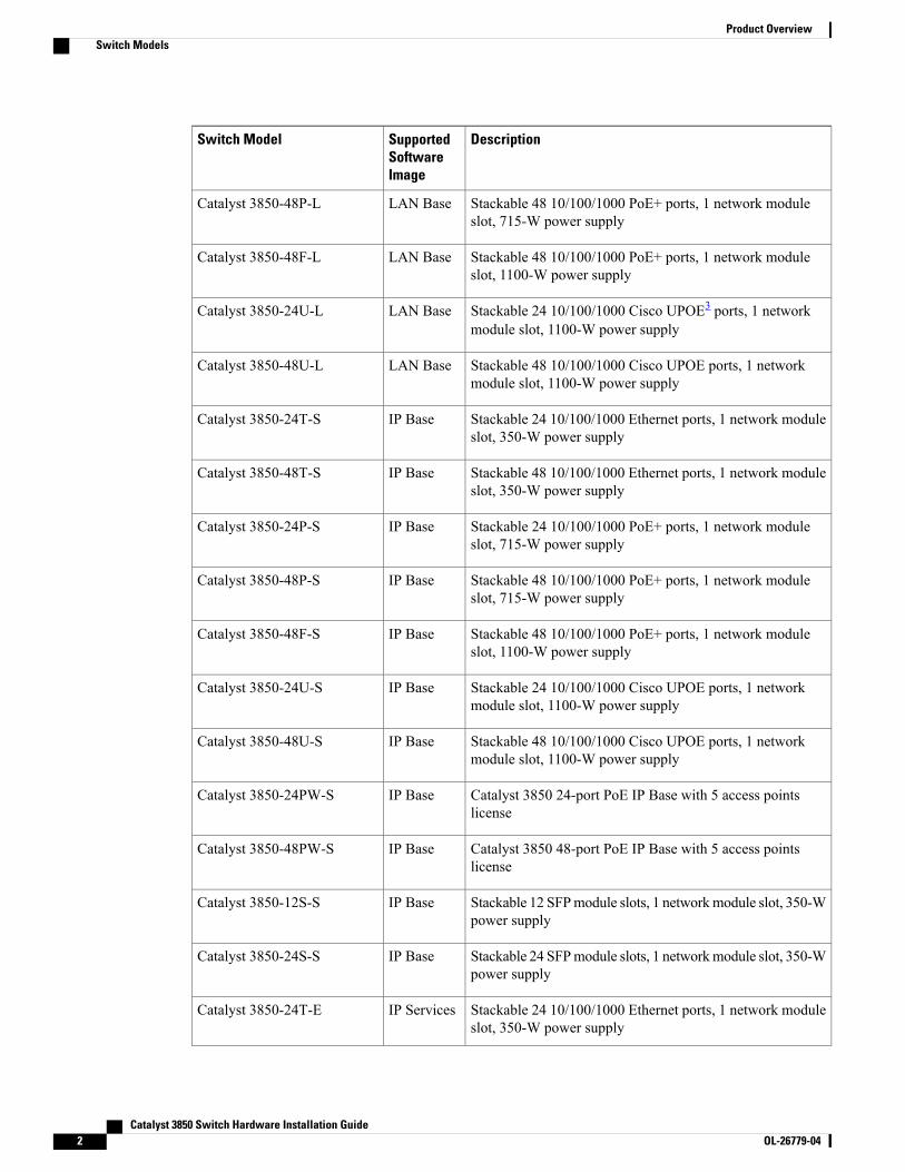
Switch ModelsTable 1: Catalyst 3850 Switch Models and Descriptions
DescriptionSupportedSoftwareImage
Switch Model
Stackable 24 10/100/1000 Ethernet ports, 1 network moduleslot1, 350-W power supply
LAN BaseCatalyst 3850-24T-L
Stackable 48 10/100/1000 Ethernet ports, 1 network moduleslot, 350-W power supply
LAN BaseCatalyst 3850-48T-L
Stackable 24 10/100/1000 PoE+2 ports, 1 network moduleslot, 715-W power supply
LAN BaseCatalyst 3850-24P-L
Catalyst 3850 Switch Hardware Installation Guide OL-26779-04 1
DescriptionSupportedSoftwareImage
Switch Model
Stackable 48 10/100/1000 PoE+ ports, 1 network moduleslot, 715-W power supply
LAN BaseCatalyst 3850-48P-L
Stackable 48 10/100/1000 PoE+ ports, 1 network moduleslot, 1100-W power supply
LAN BaseCatalyst 3850-48F-L
Stackable 24 10/100/1000 Cisco UPOE3 ports, 1 networkmodule slot, 1100-W power supply
LAN BaseCatalyst 3850-24U-L
Stackable 48 10/100/1000 Cisco UPOE ports, 1 networkmodule slot, 1100-W power supply
LAN BaseCatalyst 3850-48U-L
Stackable 24 10/100/1000 Ethernet ports, 1 network moduleslot, 350-W power supply
IP BaseCatalyst 3850-24T-S
Stackable 48 10/100/1000 Ethernet ports, 1 network moduleslot, 350-W power supply
IP BaseCatalyst 3850-48T-S
Stackable 24 10/100/1000 PoE+ ports, 1 network moduleslot, 715-W power supply
IP BaseCatalyst 3850-24P-S
Stackable 48 10/100/1000 PoE+ ports, 1 network moduleslot, 715-W power supply
IP BaseCatalyst 3850-48P-S
Stackable 48 10/100/1000 PoE+ ports, 1 network moduleslot, 1100-W power supply
IP BaseCatalyst 3850-48F-S
Stackable 24 10/100/1000 Cisco UPOE ports, 1 networkmodule slot, 1100-W power supply
IP BaseCatalyst 3850-24U-S
Stackable 48 10/100/1000 Cisco UPOE ports, 1 networkmodule slot, 1100-W power supply
IP BaseCatalyst 3850-48U-S
Catalyst 3850 24-port PoE IP Base with 5 access pointslicense
IP BaseCatalyst 3850-24PW-S
Catalyst 3850 48-port PoE IP Base with 5 access pointslicense
IP BaseCatalyst 3850-48PW-S
Stackable 12 SFPmodule slots, 1 networkmodule slot, 350-Wpower supply
IP BaseCatalyst 3850-12S-S
Stackable 24 SFPmodule slots, 1 networkmodule slot, 350-Wpower supply
IP BaseCatalyst 3850-24S-S
Stackable 24 10/100/1000 Ethernet ports, 1 network moduleslot, 350-W power supply
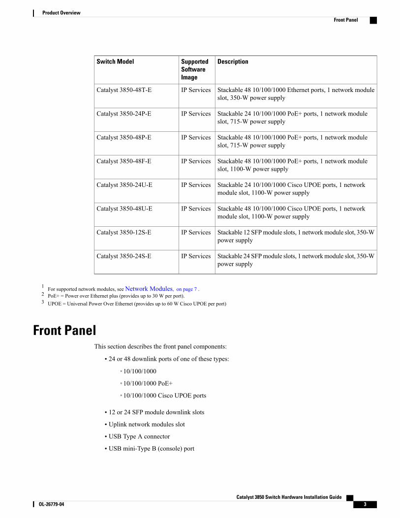
IP ServicesCatalyst 3850-24T-E
Catalyst 3850 Switch Hardware Installation Guide2 OL-26779-04
Product OverviewSwitch Models
DescriptionSupportedSoftwareImage
Switch Model
Stackable 48 10/100/1000 Ethernet ports, 1 network moduleslot, 350-W power supply
IP ServicesCatalyst 3850-48T-E
Stackable 24 10/100/1000 PoE+ ports, 1 network moduleslot, 715-W power supply
IP ServicesCatalyst 3850-24P-E
Stackable 48 10/100/1000 PoE+ ports, 1 network moduleslot, 715-W power supply
IP ServicesCatalyst 3850-48P-E
Stackable 48 10/100/1000 PoE+ ports, 1 network moduleslot, 1100-W power supply
IP ServicesCatalyst 3850-48F-E
Stackable 24 10/100/1000 Cisco UPOE ports, 1 networkmodule slot, 1100-W power supply
IP ServicesCatalyst 3850-24U-E
Stackable 48 10/100/1000 Cisco UPOE ports, 1 networkmodule slot, 1100-W power supply
IP ServicesCatalyst 3850-48U-E
Stackable 12 SFPmodule slots, 1 networkmodule slot, 350-Wpower supply
IP ServicesCatalyst 3850-12S-E
Stackable 24 SFPmodule slots, 1 networkmodule slot, 350-Wpower supply
IP ServicesCatalyst 3850-24S-E
1 For supported network modules, seeNetwork Modules, on page 7 .2 PoE+ = Power over Ethernet plus (provides up to 30 W per port).3 UPOE = Universal Power Over Ethernet (provides up to 60 W Cisco UPOE per port)
Front PanelThis section describes the front panel components:
• 24 or 48 downlink ports of one of these types:
◦10/100/1000
◦10/100/1000 PoE+
◦10/100/1000 Cisco UPOE ports
• 12 or 24 SFP module downlink slots
• Uplink network modules slot
• USB Type A connector
• USB mini-Type B (console) port
Catalyst 3850 Switch Hardware Installation Guide OL-26779-04 3
Product OverviewFront Panel
• LEDs
• Mode button
All of the switches have similar components. See the following illustrations for examples.
The Catalyst 3850 switches might have slight cosmetic differences on the bezels.Note
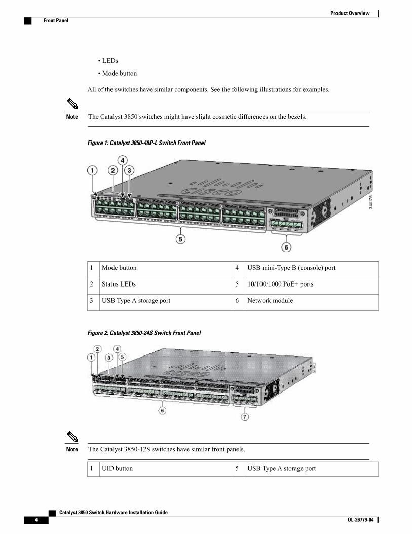
Figure 1: Catalyst 3850-48P-L Switch Front Panel
USB mini-Type B (console) port4Mode button1
10/100/1000 PoE+ ports5Status LEDs2
Network module6USB Type A storage port3
Figure 2: Catalyst 3850-24S Switch Front Panel
The Catalyst 3850-12S switches have similar front panels.Note
USB Type A storage port5UID button1
Catalyst 3850 Switch Hardware Installation Guide4 OL-26779-04
Product OverviewFront Panel
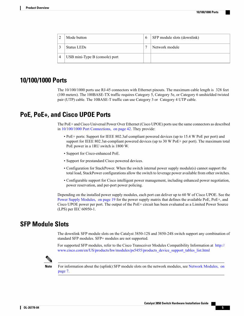
SFP module slots (downlink)6Mode button2
Network module7Status LEDs3
USB mini-Type B (console) port4
10/100/1000 PortsThe 10/100/1000 ports use RJ-45 connectors with Ethernet pinouts. The maximum cable length is 328 feet(100 meters). The 100BASE-TX traffic requires Category 5, Category 5e, or Category 6 unshielded twistedpair (UTP) cable. The 10BASE-T traffic can use Category 3 or Category 4 UTP cable.
PoE, PoE+, and Cisco UPOE PortsThe PoE+ and Cisco Universal Power Over Ethernet (Cisco UPOE) ports use the same connectors as describedin 10/100/1000 Port Connections, on page 42. They provide:
• PoE+ ports: Support for IEEE 802.3af-compliant powered devices (up to 15.4 W PoE per port) andsupport for IEEE 802.3at-compliant powered devices (up to 30 W PoE+ per port). The maximum totalPoE power in a 1RU switch is 1800 W.
• Support for Cisco-enhanced PoE.
• Support for prestandard Cisco powered devices.
• Configuration for StackPower. When the switch internal power supply module(s) cannot support thetotal load, StackPower configurations allow the switch to leverage power available from other switches.
• Configurable support for Cisco intelligent power management, including enhanced power negotiation,power reservation, and per-port power policing.
Depending on the installed power supply modules, each port can deliver up to 60 W of Cisco UPOE. See thePower Supply Modules, on page 19 for the power supply matrix that defines the available PoE, PoE+, andCisco UPOE power per port. The output of the PoE+ circuit has been evaluated as a Limited Power Source(LPS) per IEC 60950-1.
SFP Module SlotsThe downlink SFP module slots on the Catalyst 3850-12S and 3850-24S switch support any combination ofstandard SFP modules. SFP+ modules are not supported.
For supported SFP modules, refer to the Cisco Transceiver Modules Compatibility Information at http://www.cisco.com/en/US/products/hw/modules/ps5455/products_device_support_tables_list.html
For information about the (uplink) SFP module slots on the network modules, see Network Modules, onpage 7.
Note
Catalyst 3850 Switch Hardware Installation Guide OL-26779-04 5
Product Overview10/100/1000 Ports
Management PortsThe management ports connect the switch to a PC running Microsoft Windows or to a terminal server.
• Ethernet management port. See Ethernet Management Port, on page 23.
• RJ-45 console port (EIA/TIA-232). See RJ-45 Console Port, on page 23.
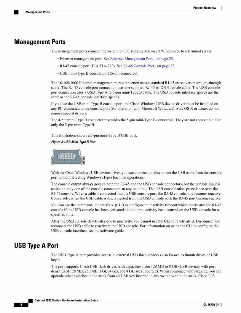
• USB mini-Type B console port (5-pin connector).
The 10/100/1000 Ethernet management port connection uses a standard RJ-45 crossover or straight-throughcable. The RJ-45 console port connection uses the supplied RJ-45-to-DB-9 female cable. The USB consoleport connection uses a USB Type A to 5-pin mini-Type B cable. The USB console interface speeds are thesame as the RJ-45 console interface speeds.
If you use the USB mini-Type B console port, the Cisco Windows USB device driver must be installed onany PC connected to the console port (for operation with Microsoft Windows). Mac OS X or Linux do notrequire special drivers.
The 4-pin mini-Type B connector resembles the 5-pin mini-Type B connectors. They are not compatible. Useonly the 5-pin mini-Type B.
This illustration shows a 5-pin mini-Type B USB port.Figure 3: USB Mini-Type B Port
With the CiscoWindows USB device driver, you can connect and disconnect the USB cable from the consoleport without affecting Windows HyperTerminal operations.
The console output always goes to both the RJ-45 and the USB console connectors, but the console input isactive on only one of the console connectors at any one time. The USB console takes precedence over theRJ-45 console.When a cable is connected into the USB console port, the RJ-45 console port becomes inactive.Conversely, when the USB cable is disconnected from the USB console port, the RJ-45 port becomes active.
You can use the command-line interface (CLI) to configure an inactivity timeout which reactivates the RJ-45console if the USB console has been activated and no input activity has occurred on the USB console for aspecified time.
After the USB console deactivates due to inactivity, you cannot use the CLI to reactivate it. Disconnect andreconnect the USB cable to reactivate the USB console. For information on using the CLI to configure theUSB console interface, see the software guide.
USB Type A PortThe USB Type A port provides access to external USB flash devices (also known as thumb drives or USBkeys).
The port supports Cisco USB flash drives with capacities from 128 MB to 8 GB (USB devices with portdensities of 128 MB, 256 MB, 1 GB, 4 GB, and 8 GB are supported). When combined with stacking, you canupgrade other switches in the stack from an USB key inserted in any switch within the stack. Cisco IOS
Catalyst 3850 Switch Hardware Installation Guide6 OL-26779-04
Product OverviewManagement Ports
software provides standard file system access to the flash device: read, write, erase, and copy, as well as theability to format the flash device with a FAT file system. It provides you with the ability to automaticallyupgrade the internal flash with the USB drive’s configuration and image for emergency switch recovery usingUSB auto-upgrade. This feature checks the internal flash for a bootable image and configuration and if eitherimage or the configuration is not available, then the USB drive is checked for boot images and configuration.If the boot image and configuration are available, these are copied to flash for the reboot.
Network ModulesThe switch supports one hot-swappable network module that provides uplink ports to connect to other devices.The switch should only be operated with either a network module or a blank module installed.
The switch generates logs when you insert or remove a network module with SFP ports.
Table 2: Network Modules
DescriptionNetwork Module4
This module has four 1-Gigabit SFP module slots. Any combination of standardSFP modules are supported. SFP+ modules are not supported.
If you insert an SFP+module in the 1-Gigabit network module, the SFP+moduledoes not operate, and the switch logs an error message.
C3850-NM-4-1G
This module has four slots:
Two slots (left side) support only 1-Gigabit SFP modules and two slots (rightside) support either 1-Gigabit SFP or 10-Gigabit SFP modules.
C3850-NM-2-10G
This module has four 10-Gigabit slots or four 1-Gigabit slots.
This module is supported only on the 48-port switches.Note
C3850-NM-4-10G
This module has no uplink ports.C3850-NM-BLANK
4 All network modules are hot-swappable.
For information about the network modules, see the Installing Network Modules, on page 50. For cablespecifications, see Cables and Adapters, on page 89.
SFP and SFP+ ModulesThe SFP and SFP+ modules provide copper or fiber-optic connections to other devices. These transceivermodules are field-replaceable, and they provide the uplink interfaces (expect in the fixed SFP slots in theCatalyst 3850-12S and 3850-24S) when installed in an SFPmodule slot. The SFPmodules have LC connectorsfor fiber-optic connections or RJ-45 connectors for copper connections.
The (downlink) SFP module slots on the Catalyst 3850-12S and 3850-24S switch front panel support anycombination of standard SFP modules. SFP+ modules are not supported.
Note
Catalyst 3850 Switch Hardware Installation Guide OL-26779-04 7
Product OverviewNetwork Modules
Use only Cisco SFP and SFP+ modules on the switch. For the latest information about supported SFP andSFP+ modules, refer to the Cisco Transceiver Modules Compatibility Information at http://www.cisco.com/en/US/products/hw/modules/ps5455/products_device_support_tables_list.html
For information about SFPmodules, see the SFPmodule documentation and Installing SFP and SFP+Modules,on page 54.
The Catalyst 3850 switch supports the SFP module patch cable (CAB-SFP-50CM), a 0.5-meter, copper,passive cable with SFP module connectors at each end. This cable is only used with 1-Gigabit Ethernet SFPports to connect two Catalyst 3850 switches in a cascaded configuration.
LEDsYou can use the switch LEDs to monitor switch activity and its performance.
Catalyst 3850 switches might have slight cosmetic differences on the bezels.Note
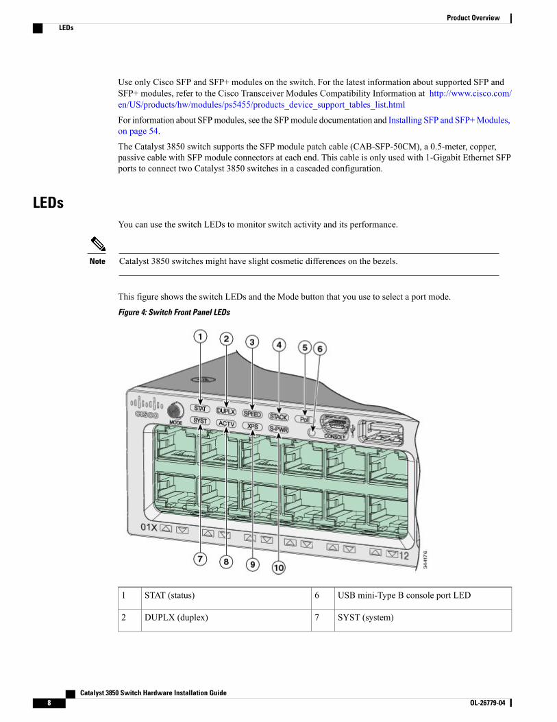
This figure shows the switch LEDs and the Mode button that you use to select a port mode.
Figure 4: Switch Front Panel LEDs
USB mini-Type B console port LED6STAT (status)1
SYST (system)7DUPLX (duplex)2
Catalyst 3850 Switch Hardware Installation Guide8 OL-26779-04
Product OverviewLEDs
ACTV (active)8SPEED3
XPS 569STACK4
S-PWR (StackPower)10PoE 75
5 XPS = expandable power system.6 The XPS 2200 is not supported in this release.7 Only on switch models that support PoE.
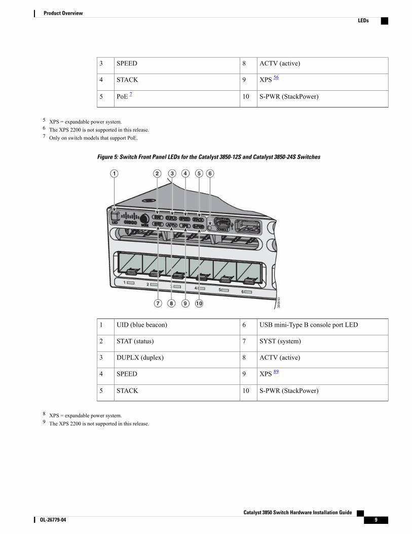
Figure 5: Switch Front Panel LEDs for the Catalyst 3850-12S and Catalyst 3850-24S Switches
USB mini-Type B console port LED6UID (blue beacon)1
SYST (system)7STAT (status)2
ACTV (active)8DUPLX (duplex)3
XPS 899SPEED4
S-PWR (StackPower)10STACK5
8 XPS = expandable power system.9 The XPS 2200 is not supported in this release.
Catalyst 3850 Switch Hardware Installation Guide OL-26779-04 9
Product OverviewLEDs
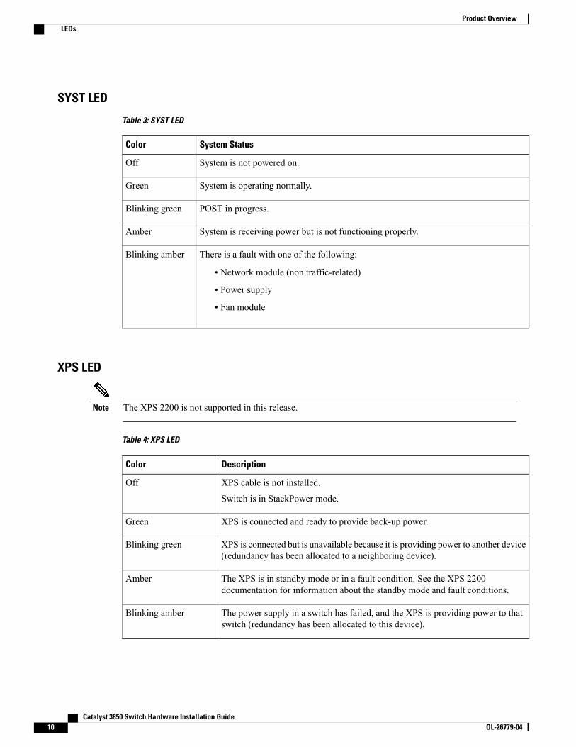
SYST LED
Table 3: SYST LED
System StatusColor
System is not powered on.Off
System is operating normally.Green
POST in progress.Blinking green
System is receiving power but is not functioning properly.Amber
There is a fault with one of the following:
• Network module (non traffic-related)
• Power supply
• Fan module
Blinking amber
XPS LED
The XPS 2200 is not supported in this release.Note
Table 4: XPS LED
DescriptionColor
XPS cable is not installed.
Switch is in StackPower mode.
Off
XPS is connected and ready to provide back-up power.Green
XPS is connected but is unavailable because it is providing power to another device(redundancy has been allocated to a neighboring device).
Blinking green
The XPS is in standby mode or in a fault condition. See the XPS 2200documentation for information about the standby mode and fault conditions.
Amber
The power supply in a switch has failed, and the XPS is providing power to thatswitch (redundancy has been allocated to this device).
Blinking amber
Catalyst 3850 Switch Hardware Installation Guide10 OL-26779-04
Product OverviewLEDs
For information about the XPS 2200, see the Cisco eXpandable Power System 2200 Hardware InstallationGuide on Cisco.com:
http://www.cisco.com/go/xps2200_hw
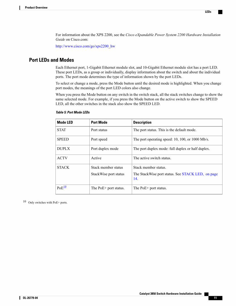
Port LEDs and ModesEach Ethernet port, 1-Gigabit Ethernet module slot, and 10-Gigabit Ethernet module slot has a port LED.These port LEDs, as a group or individually, display information about the switch and about the individualports. The port mode determines the type of information shown by the port LEDs.
To select or change a mode, press the Mode button until the desired mode is highlighted. When you changeport modes, the meanings of the port LED colors also change.
When you press the Mode button on any switch in the switch stack, all the stack switches change to show thesame selected mode. For example, if you press the Mode button on the active switch to show the SPEEDLED, all the other switches in the stack also show the SPEED LED.
Table 5: Port Mode LEDs
DescriptionPort ModeMode LED
The port status. This is the default mode.Port statusSTAT
The port operating speed: 10, 100, or 1000 Mb/s.Port speedSPEED
The port duplex mode: full duplex or half duplex.Port duplex modeDUPLX
The active switch status.ActiveACTV
Stack member status.
The StackWise port status. See STACK LED, on page14.
Stack member status
StackWise port status
STACK
The PoE+ port status.The PoE+ port status.PoE10
10 Only switches with PoE+ ports.
Catalyst 3850 Switch Hardware Installation Guide OL-26779-04 11
Product OverviewLEDs
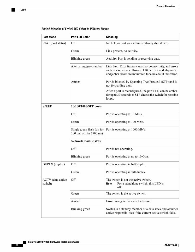
Table 6: Meaning of Switch LED Colors in Different Modes
MeaningPort LED ColorPort Mode
No link, or port was administratively shut down.OffSTAT (port status)
Link present, no activity.Green
Activity. Port is sending or receiving data.Blinking green
Link fault. Error frames can affect connectivity, and errorssuch as excessive collisions, CRC errors, and alignmentand jabber errors are monitored for a link-fault indication.
Alternating green-amber
Port is blocked by Spanning Tree Protocol (STP) and isnot forwarding data.
After a port is reconfigured, the port LED can be amberfor up to 30 seconds as STP checks the switch for possibleloops.
Amber
10/100/1000/SFP portsSPEED
Port is operating at 10 Mb/s.Off
Port is operating at 100 Mb/s.Green
Port is operating at 1000 Mb/s.Single green flash (on for100 ms, off for 1900 ms)
Network module slots
Port is not operating.Off
Port is operating at up to 10 Gb/s.Blinking green
Port is operating in half duplex.OffDUPLX (duplex)
Port is operating in full duplex.Green
The switch is not the active switch.For a standalone switch, this LED isoff.
NoteOffACTV (data active
switch)
The switch is the active switch.Green
Error during active switch election.Amber
Switch is a standby member of a data stack and assumesactive responsibilities if the current active switch fails.
Blinking green
Catalyst 3850 Switch Hardware Installation Guide12 OL-26779-04
Product OverviewLEDs
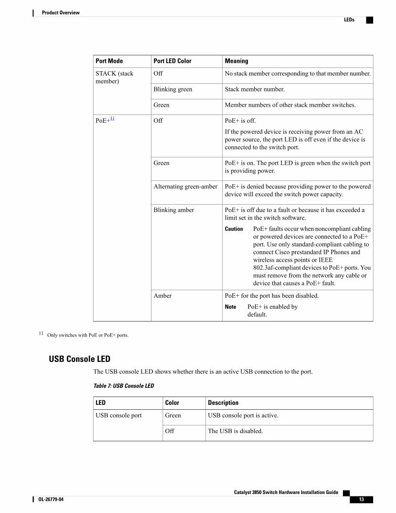
MeaningPort LED ColorPort Mode
No stack member corresponding to that member number.OffSTACK (stackmember)
Stack member number.Blinking green
Member numbers of other stack member switches.Green
PoE+ is off.
If the powered device is receiving power from an ACpower source, the port LED is off even if the device isconnected to the switch port.
OffPoE+11
PoE+ is on. The port LED is green when the switch portis providing power.
Green
PoE+ is denied because providing power to the powereddevice will exceed the switch power capacity.
Alternating green-amber
PoE+ is off due to a fault or because it has exceeded alimit set in the switch software.
PoE+ faults occur when noncompliant cablingor powered devices are connected to a PoE+port. Use only standard-compliant cabling toconnect Cisco prestandard IP Phones andwireless access points or IEEE802.3af-compliant devices to PoE+ ports. Youmust remove from the network any cable ordevice that causes a PoE+ fault.
Caution
Blinking amber
PoE+ for the port has been disabled.
PoE+ is enabled bydefault.
Note
Amber
11 Only switches with PoE or PoE+ ports.
USB Console LEDThe USB console LED shows whether there is an active USB connection to the port.
Table 7: USB Console LED
DescriptionColorLED
USB console port is active.GreenUSB console port
The USB is disabled.Off
Catalyst 3850 Switch Hardware Installation Guide OL-26779-04 13
Product OverviewLEDs
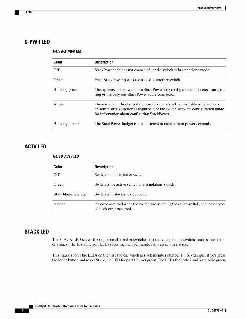
S-PWR LED
Table 8: S-PWR LED
DescriptionColor
StackPower cable is not connected, or the switch is in standalone mode.Off
Each StackPower port is connected to another switch.Green
This appears on the switch in a StackPower ring configuration that detects an openring or has only one StackPower cable connected.
Blinking green
There is a fault: load shedding is occurring, a StackPower cable is defective, oran administrative action is required. See the switch software configuration guidefor information about configuring StackPower.
Amber
The StackPower budget is not sufficient to meet current power demands.Blinking amber
ACTV LED
Table 9: ACTV LED
DescriptionColor
Switch is not the active switch.Off
Switch is the active switch or a standalone switch.Green
Switch is in stack standby mode.Slow blinking green
An error occurred when the switch was selecting the active switch, or another typeof stack error occurred.
Amber
STACK LEDThe STACK LED shows the sequence of member switches in a stack. Up to nine switches can be membersof a stack. The first nine port LEDs show the member number of a switch in a stack.
This figure shows the LEDs on the first switch, which is stack member number 1. For example, if you pressthe Mode button and select Stack, the LED for port 1 blinks green. The LEDs for ports 2 and 3 are solid green,
Catalyst 3850 Switch Hardware Installation Guide14 OL-26779-04
Product OverviewLEDs
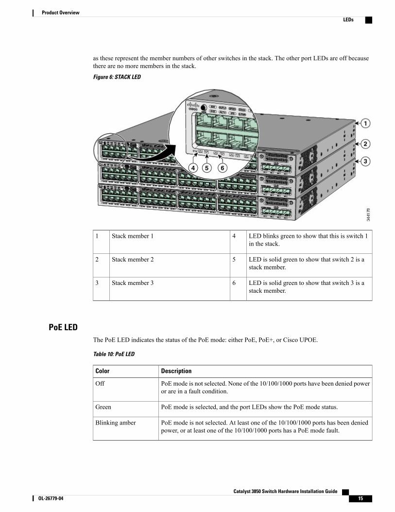
as these represent the member numbers of other switches in the stack. The other port LEDs are off becausethere are no more members in the stack.
Figure 6: STACK LED
LED blinks green to show that this is switch 1in the stack.
4Stack member 11
LED is solid green to show that switch 2 is astack member.
5Stack member 22
LED is solid green to show that switch 3 is astack member.
6Stack member 33
PoE LEDThe PoE LED indicates the status of the PoE mode: either PoE, PoE+, or Cisco UPOE.
Table 10: PoE LED
DescriptionColor
PoE mode is not selected. None of the 10/100/1000 ports have been denied poweror are in a fault condition.
Off
PoE mode is selected, and the port LEDs show the PoE mode status.Green
PoE mode is not selected. At least one of the 10/100/1000 ports has been deniedpower, or at least one of the 10/100/1000 ports has a PoE mode fault.
Blinking amber
Catalyst 3850 Switch Hardware Installation Guide OL-26779-04 15
Product OverviewLEDs
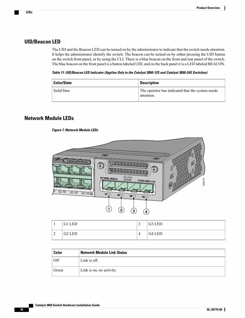
UID/Beacon LEDThe UID and the Beacon LED can be turned on by the administrator to indicate that the switch needs attention.It helps the administrator identify the switch. The beacon can be turned on by either pressing the UID buttonon the switch front panel, or by using the CLI. There is a blue beacon on the front and rear panel of the switch.The blue beacon on the front panel is a button labeled UID, and on the back panel it is a LED labeled BEACON.
Table 11: UID/Beacon LED Indicator (Applies Only to the Catalyst 3850-12S and Catalyst 3850-24S Switches)
DescriptionColor/State
The operator has indicated that the system needsattention.
Solid blue
Network Module LEDs
Figure 7: Network Module LEDs
G3 LED3G1 LED1
G4 LED4G2 LED2
Network Module Link StatusColor
Link is off.Off
Link is on; no activity.Green
Catalyst 3850 Switch Hardware Installation Guide16 OL-26779-04
Product OverviewLEDs
Network Module Link StatusColor
Activity on a link; no faults.
The LED will blink green even when there is very little controltraffic.
Note
Blinking green
Link is off due to a fault or because it has exceeded a limit set in the switch software.
Link faults occur when noncompliant cabling is connected to an SFP or SFP+port. Use only standard-compliant cabling to connect to Cisco SFP and SFP+ports. You must remove from the network any cable or device that causes alink fault.
Caution
Blinking amber
Link for the SFP or SFP+ has been disabled.Amber
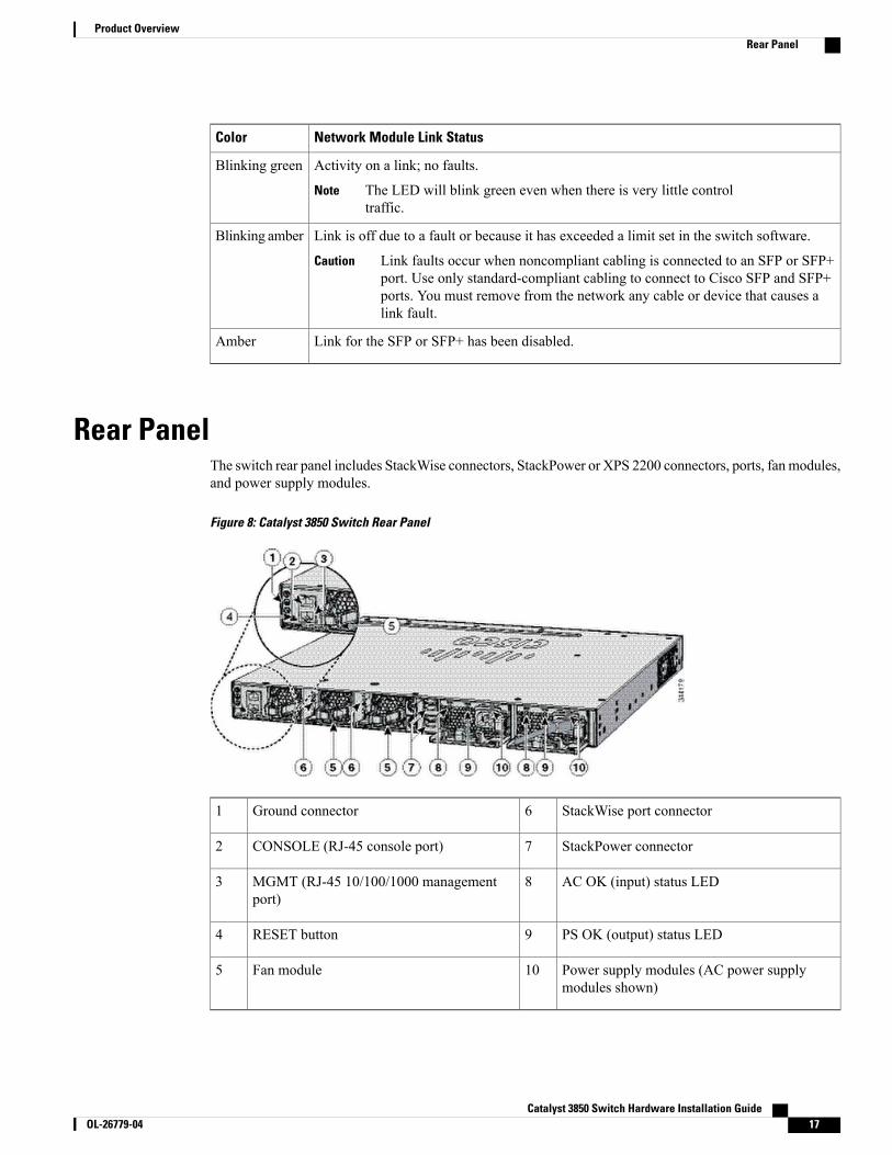
Rear PanelThe switch rear panel includes StackWise connectors, StackPower or XPS 2200 connectors, ports, fan modules,and power supply modules.
Figure 8: Catalyst 3850 Switch Rear Panel
StackWise port connector6Ground connector1
StackPower connector7CONSOLE (RJ-45 console port)2
AC OK (input) status LED8MGMT (RJ-45 10/100/1000 managementport)
3
PS OK (output) status LED9RESET button4
Power supply modules (AC power supplymodules shown)
10Fan module5
Catalyst 3850 Switch Hardware Installation Guide OL-26779-04 17
Product OverviewRear Panel
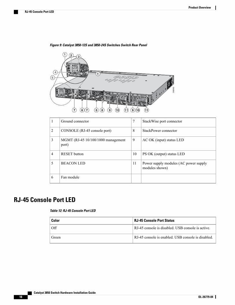
Figure 9: Catalyst 3850-12S and 3850-24S Switches Switch Rear Panel
StackWise port connector7Ground connector1
StackPower connector8CONSOLE (RJ-45 console port)2
AC OK (input) status LED9MGMT (RJ-45 10/100/1000 managementport)
3
PS OK (output) status LED10RESET button4
Power supply modules (AC power supplymodules shown)
11BEACON LED5
Fan module6
RJ-45 Console Port LEDTable 12: RJ-45 Console Port LED
RJ-45 Console Port StatusColor
RJ-45 console is disabled. USB console is active.Off
RJ-45 console is enabled. USB console is disabled.Green
Catalyst 3850 Switch Hardware Installation Guide18 OL-26779-04
Product OverviewRJ-45 Console Port LED
StackWise PortsStackWise ports are used to connect switches in StackWise stacking configurations. The Catalyst 3850 switchships with a 0.5-meter StackWise cable that you can use to connect the StackWise ports. For more informationon StackWise cables, see Connecting to the StackWise Ports, on page 39.
Use only approved cables, and connect only to similar Cisco equipment. Equipment might be damagedif connected to nonapproved Cisco cables or equipment.
Caution
Power Supply Modules
The switches are powered through one or two internal power supply modules.
Supported power supply modules:
• PWR-C1-350WAC
• PWR-C1-715WAC
• PWR-C1-1100WAC
• PWR-C1-440WDC
The switch has two internal power supply module slots. You can use two AC modules, two DC modules, amixed configuration of one AC and one DC power supply module, or one power supply module and a blankmodule.
The switch can operate with either one or two active power supply modules or with power supplied by a stack.A Catalyst 3850 switch that is in a StackPower stack can operate with power supplied by other switches inthe stack.
Switch Models, on page 1 shows the default power supply modules that ship with each switch model. Allpower supply modules (except the blank modules) have internal fans. All switches ship with a blank powersupply module in the second power supply slot.
Do not operate the switch with one power supply module slot empty. For proper chassis cooling, bothpower supply module slots must be populated with either a power supply or a blank module.
Caution
The 350-W and 715-W AC power supply modules are autoranging units that support input voltages between100 and 240 VAC. The 1100-W power supply module is an autoranging unit that supports input voltagesbetween 115 and 240 VAC. The 440-WDC power supply module has dual input feeds (A and B) and supportsinput voltages between 36 and 72 VDC. The output voltage range is 51 to 57 V.
Each AC power supply module has a power cord for connection to an AC power outlet. The 1100-W and715-W modules use a 16-AWG cord (only North America). All other modules use an 18-AWG cord. TheDC-power supply module must be wired to a DC-power source.
The following tables show the PoE available and PoE requirements for Catalyst 3850 PoE switch models.
Catalyst 3850 Switch Hardware Installation Guide OL-26779-04 19
Product OverviewStackWise Ports
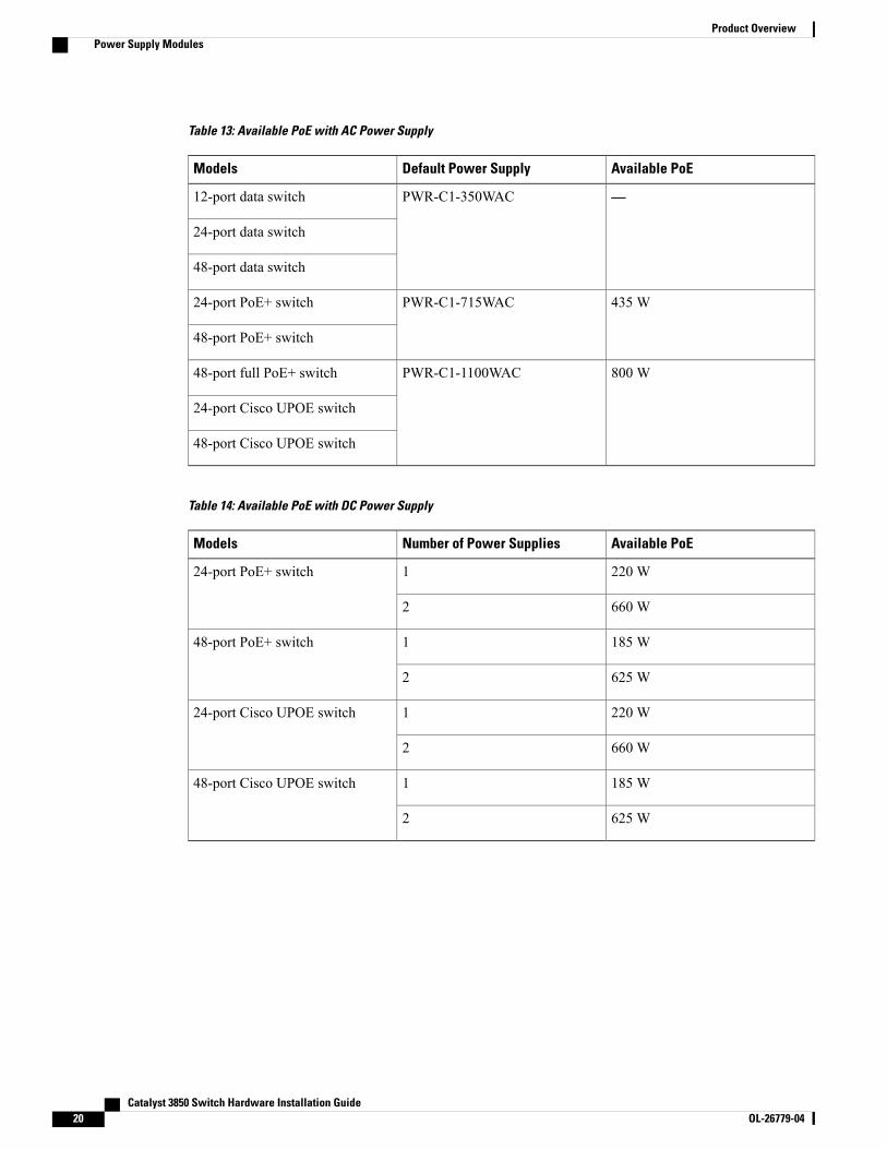
Table 13: Available PoE with AC Power Supply
Available PoEDefault Power SupplyModels
—PWR-C1-350WAC12-port data switch
24-port data switch
48-port data switch
435 WPWR-C1-715WAC24-port PoE+ switch
48-port PoE+ switch
800 WPWR-C1-1100WAC48-port full PoE+ switch
24-port Cisco UPOE switch
48-port Cisco UPOE switch
Table 14: Available PoE with DC Power Supply
Available PoENumber of Power SuppliesModels
220 W124-port PoE+ switch
660 W2
185 W148-port PoE+ switch
625 W2
220 W124-port Cisco UPOE switch
660 W2
185 W148-port Cisco UPOE switch
625 W2
Catalyst 3850 Switch Hardware Installation Guide20 OL-26779-04
Product OverviewPower Supply Modules
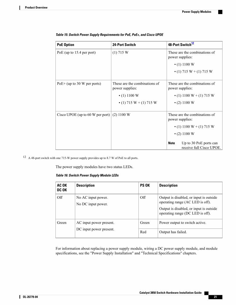
Table 15: Switch Power Supply Requirements for PoE, PoE+, and Cisco UPOE
48-Port Switch1224-Port SwitchPoE Option
These are the combinations ofpower supplies:
• (1) 1100 W
• (1) 715 W + (1) 715 W
(1) 715 WPoE (up to 15.4 per port)
These are the combinations ofpower supplies:
• (1) 1100 W + (1) 715 W
• (2) 1100 W
These are the combinations ofpower supplies:
• (1) 1100 W
• (1) 715 W + (1) 715 W
PoE+ (up to 30 W per ports)
These are the combinations ofpower supplies:
• (1) 1100 W + (1) 715 W
• (2) 1100 W
Up to 30 PoE ports canreceive full Cisco UPOE.
Note
(2) 1100 WCisco UPOE (up to 60 W per port)
12 A 48-port switch with one 715-W power supply provides up to 8.7 W of PoE to all ports.
The power supply modules have two status LEDs.
Table 16: Switch Power Supply Module LEDs
DescriptionPS OKDescriptionAC OKDC OK
Output is disabled, or input is outsideoperating range (AC LED is off).
Output is disabled, or input is outsideoperating range (DC LED is off).
OffNo AC input power.
No DC input power.
Off
Power output to switch active.GreenAC input power present.
DC input power present.
Green
Output has failed.Red
For information about replacing a power supply module, wiring a DC power supply module, and modulespecifications, see the "Power Supply Installation" and "Technical Specifications" chapters.
Catalyst 3850 Switch Hardware Installation Guide OL-26779-04 21
Product OverviewPower Supply Modules
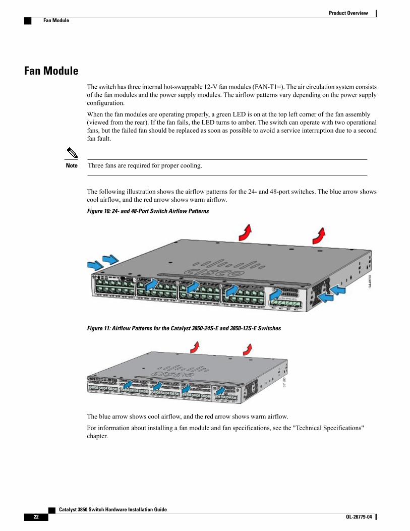
Fan ModuleThe switch has three internal hot-swappable 12-V fan modules (FAN-T1=). The air circulation system consistsof the fan modules and the power supply modules. The airflow patterns vary depending on the power supplyconfiguration.
When the fan modules are operating properly, a green LED is on at the top left corner of the fan assembly(viewed from the rear). If the fan fails, the LED turns to amber. The switch can operate with two operationalfans, but the failed fan should be replaced as soon as possible to avoid a service interruption due to a secondfan fault.
Three fans are required for proper cooling.Note
The following illustration shows the airflow patterns for the 24- and 48-port switches. The blue arrow showscool airflow, and the red arrow shows warm airflow.
Figure 10: 24- and 48-Port Switch Airflow Patterns
Figure 11: Airflow Patterns for the Catalyst 3850-24S-E and 3850-12S-E Switches
The blue arrow shows cool airflow, and the red arrow shows warm airflow.
For information about installing a fan module and fan specifications, see the "Technical Specifications"chapter.
Catalyst 3850 Switch Hardware Installation Guide22 OL-26779-04
Product OverviewFan Module
StackPower ConnectorThe Catalyst 3850 switches have a StackPower connector for use with Cisco StackPower cables to configurea switch power stack that includes up to nine switches. A switch power stack can be configured in redundantor power-sharing mode.
You can order these StackPower cables from your Cisco sales representative:
• CAB-SPWR-30CM (0.3-meter cable)
• CAB-SPWR-150CM (1.5-meter cable)
For details about connecting StackPower cables and StackPower guidelines, see Planning a StackPower Stack,on page 32.
Management Ports
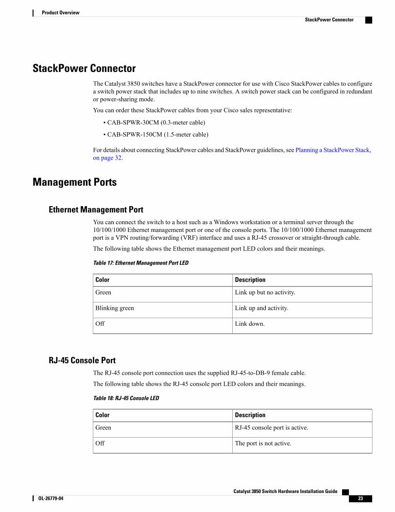
Ethernet Management PortYou can connect the switch to a host such as a Windows workstation or a terminal server through the10/100/1000 Ethernet management port or one of the console ports. The 10/100/1000 Ethernet managementport is a VPN routing/forwarding (VRF) interface and uses a RJ-45 crossover or straight-through cable.
The following table shows the Ethernet management port LED colors and their meanings.
Table 17: Ethernet Management Port LED
DescriptionColor
Link up but no activity.Green
Link up and activity.Blinking green
Link down.Off
RJ-45 Console PortThe RJ-45 console port connection uses the supplied RJ-45-to-DB-9 female cable.
The following table shows the RJ-45 console port LED colors and their meanings.
Table 18: RJ-45 Console LED
DescriptionColor
RJ-45 console port is active.Green
The port is not active.Off
Catalyst 3850 Switch Hardware Installation Guide OL-26779-04 23
Product OverviewStackPower Connector
Management Options• Cisco Network AssistantCisco Network Assistant is a PC-based network management GUI application for LANs. You can usethe GUI to configure and manage switch clusters or standalone switches. Cisco Network Assistant isavailable at no cost and can be downloaded from this URL: http://www.cisco.com/pcgi-bin/tablebuild.pl/NetworkAssistant
• Cisco IOS CLIYou can configure and monitor the switch and switch cluster members from the CLI. You can accessthe CLI by connecting your management station directly to the switch console port or by using Telnetfrom a remotemanagement station. See the switch command reference onCisco.com formore information.
• Cisco Prime InfrastructureCisco Prime Infrastructure combines the wireless functionality of Cisco Prime Network Control System(NCS) and the wired functionality of Cisco Prime LANManagement Solution (LMS), with applicationperformance monitoring and troubleshooting capabilities of Cisco Prime Assurance Manager. For moreinformation, see the Cisco Prime Infrastructure documentation on Cisco.com: http://www.cisco.com/en/US/products/ps12239/index.html
Catalyst 3850 Switch Hardware Installation Guide24 OL-26779-04
Product OverviewManagement Options
C H A P T E R 2Switch Installation
For initial switch setup, assigning the switch IP address, and powering on information, see the switch gettingstarted guide on Cisco.com.
This chapter contains these topics:
• Preparing for Installation, page 25
• Planning a Switch Data Stack, page 28
• Data Stack Cabling Configurations, page 29
• Planning a StackPower Stack, page 32
• StackPower Cabling Configurations, page 33
• Installing the Switch, page 35
• Connecting to the StackWise Ports, page 39
• Connecting to the StackPower Ports, page 41
• Installing a Network Module in the Switch, page 41
• Installing and Removing SFP and SFP+ Modules, page 42
• Connecting Devices to the Ethernet Ports, page 42
• Where to Go Next, page 44
Preparing for Installation
Safety WarningsThis section includes the basic installation caution and warning statements. Read this section before you startthe installation procedure. Translations of the warning statements appear in the Catalyst 3850 switch RCSIguide on Cisco.com.
Catalyst 3850 Switch Hardware Installation Guide OL-26779-04 25
Before working on equipment that is connected to power lines, remove jewelry (including rings, necklaces,and watches). Metal objects will heat up when connected to power and ground and can cause serious burnsor weld the metal object to the terminals. Statement 43
Warning
Do not stack the chassis on any other equipment. If the chassis falls, it can cause severe bodily injury andequipment damage. Statement 48
Warning
Ethernet cables must be shielded when used in a central office environment. Statement 171Warning
Do not work on the system or connect or disconnect cables during periods of lightning activity. Statement1001
Warning
Read the installation instructions before connecting the system to the power source. Statement 1004Warning
Class 1 laser product. Statement 1008Warning
This unit is intended for installation in restricted access areas. A restricted access area can be accessedonly through the use of a special tool, lock and key, or other means of security. Statement 1017
Warning
The plug-socket combination must be accessible at all times, because it serves as the main disconnectingdevice. Statement 1019
Warning
Use copper conductors only. Statement 1025Warning
This unit might have more than one power supply connection. All connections must be removed tode-energize the unit. Statement 1028
Warning
Only trained and qualified personnel should be allowed to install, replace, or service this equipment.Statement 1030
Warning
Catalyst 3850 Switch Hardware Installation Guide26 OL-26779-04
Switch InstallationSafety Warnings
Ultimate disposal of this product should be handled according to all national laws and regulations. Statement1040
Warning
To prevent the system from overheating, do not operate it in an area that exceeds the maximumrecommended ambient temperature of: <113°F (45°C). Statement 1047
Warning
Installation of the equipment must comply with local and national electrical codes. Statement 1074Warning
To prevent airflow restriction, allow clearance around the ventilation openings to be at least: 3 inches (7.6cm). Statement 1076
Warning
The grounding architecture of this product is DC-isolated (DC-I).Note
Installation GuidelinesWhen determining where to install the switch, verify that these guidelines are met:
• Clearance to the switch front and rear panel meets these conditions:
◦Front-panel LEDs can be easily read.
◦Access to ports is sufficient for unrestricted cabling.
◦AC power cord can reach from the AC power outlet to the connector on the switch rear panel.
◦The SFP or SFP+ module minimum bend radius and connector length is met. See the SFP or SFP+module documentation for more information.
• Cabling is away from sources of electrical noise, such as radios, power lines, and fluorescent lightingfixtures. Make sure that the cabling is safely away from other devices that might damage the cables.
• For switches with the optional 1100-W power-supply module (PWR-C1-1100WAC=), first rack-mountthe switch before installing the power-supply module.
• Make sure power-supply modules and fan modules are securely inserted in the chassis before movingthe switch.
•When connecting or disconnecting the power cord on a switch that is installed above or below a 1100-Wpower supply-equipped switch, you might need to remove the module from the switch to access thepower cord.
• Airflow around the switch and through the vents is unrestricted.
• For copper connections on Ethernet ports, cable lengths from the switch to connected devices can be upto 328 feet (100 meters).
Catalyst 3850 Switch Hardware Installation Guide OL-26779-04 27
Switch InstallationInstallation Guidelines
• Temperature around the unit does not exceed 113°F (45°C). If the switch is installed in a closed ormultirack assembly, the temperature around it might be greater than normal room temperature.
• Humidity around the switch does not exceed 95 percent.
• Altitude at the installation site is not greater than 10,000 feet.
• Cooling mechanisms, such as fans and blowers in the switch, can draw dust and other particles causingcontaminant buildup inside the chassis, which can result in system malfunction. You must install thisequipment in an environment as free from dust and foreign conductive material (such as metal flakesfrom construction activities) as is possible.
Box ContentsThe switch getting started guide describes the box contents. If any item is missing or damaged, contact yourCisco representative or reseller for support.
Tools and EquipmentObtain these necessary tools and equipment:
• A number-2 Phillips screwdriver to rack-mount the switch.
Verifying Switch OperationBefore you install the switch in a rack, or on a table or shelf, you should power on the switch and verify thatthe switch passes POST. See the “Running Express Setup” section in the getting started guide for the stepsrequired to connect a PC to the switch and to run Express Setup.
Powering Off the SwitchAfter a successful POST, disconnect the power cord from the switch. Install the switch in a rack, on a table,or on a shelf as described in Installing the Switch, on page 35.
Planning a Switch Data StackCatalyst 3850 switches can share bandwidth by using data stacking.
Switch Stacking and Power Stacking GuidelinesBefore connecting the switches in a stack, keep in mind these stacking guidelines:
• Size of the switch and any optional power-supply module. The 1100-W power-supply module is longerthan the other modules. Stacking switches with the same power-supply modules together makes it easierto cable the switches.
Catalyst 3850 Switch Hardware Installation Guide28 OL-26779-04
Switch InstallationBox Contents
• Length of cable. Depending on the configurations that you have, you might need different-sized cables.If you do not specify the length of the StackWise cable, the 0.5-meter cable is supplied. If you need the1-meter cable or the 3-meter cable, you can order it from your Cisco supplier. For cable part numbers,see StackWise Ports, on page 19. The Data Stack Cabling Configurations, on page 29 provides examplesof recommended configurations.
• For rack-mounted switch stacks that are members of a StackPower stack as well as a data stack, seePlanning a StackPower Stack, on page 32.
• You can create data stacks with up to nine switches in a stack.
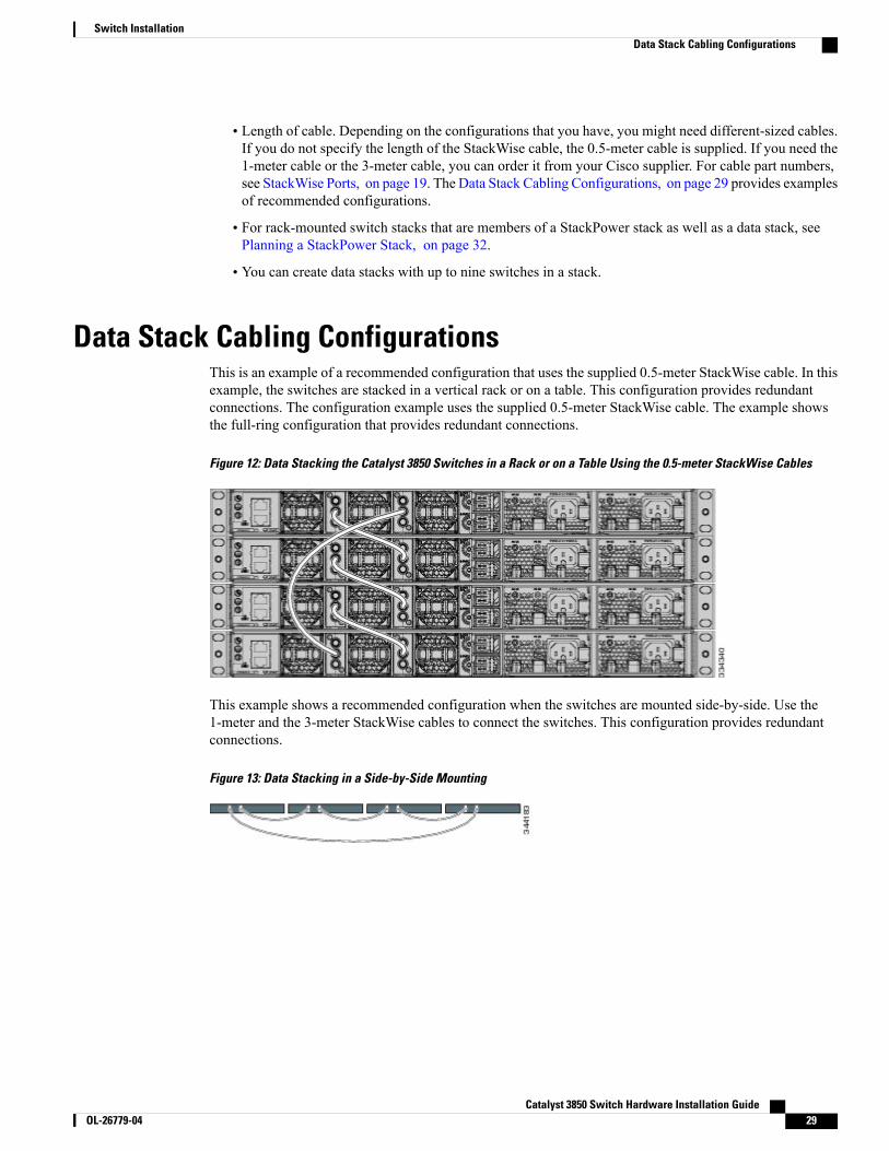
Data Stack Cabling ConfigurationsThis is an example of a recommended configuration that uses the supplied 0.5-meter StackWise cable. In thisexample, the switches are stacked in a vertical rack or on a table. This configuration provides redundantconnections. The configuration example uses the supplied 0.5-meter StackWise cable. The example showsthe full-ring configuration that provides redundant connections.
Figure 12: Data Stacking the Catalyst 3850 Switches in a Rack or on a Table Using the 0.5-meter StackWise Cables
This example shows a recommended configuration when the switches are mounted side-by-side. Use the1-meter and the 3-meter StackWise cables to connect the switches. This configuration provides redundantconnections.
Figure 13: Data Stacking in a Side-by-Side Mounting
Catalyst 3850 Switch Hardware Installation Guide OL-26779-04 29
Switch InstallationData Stack Cabling Configurations
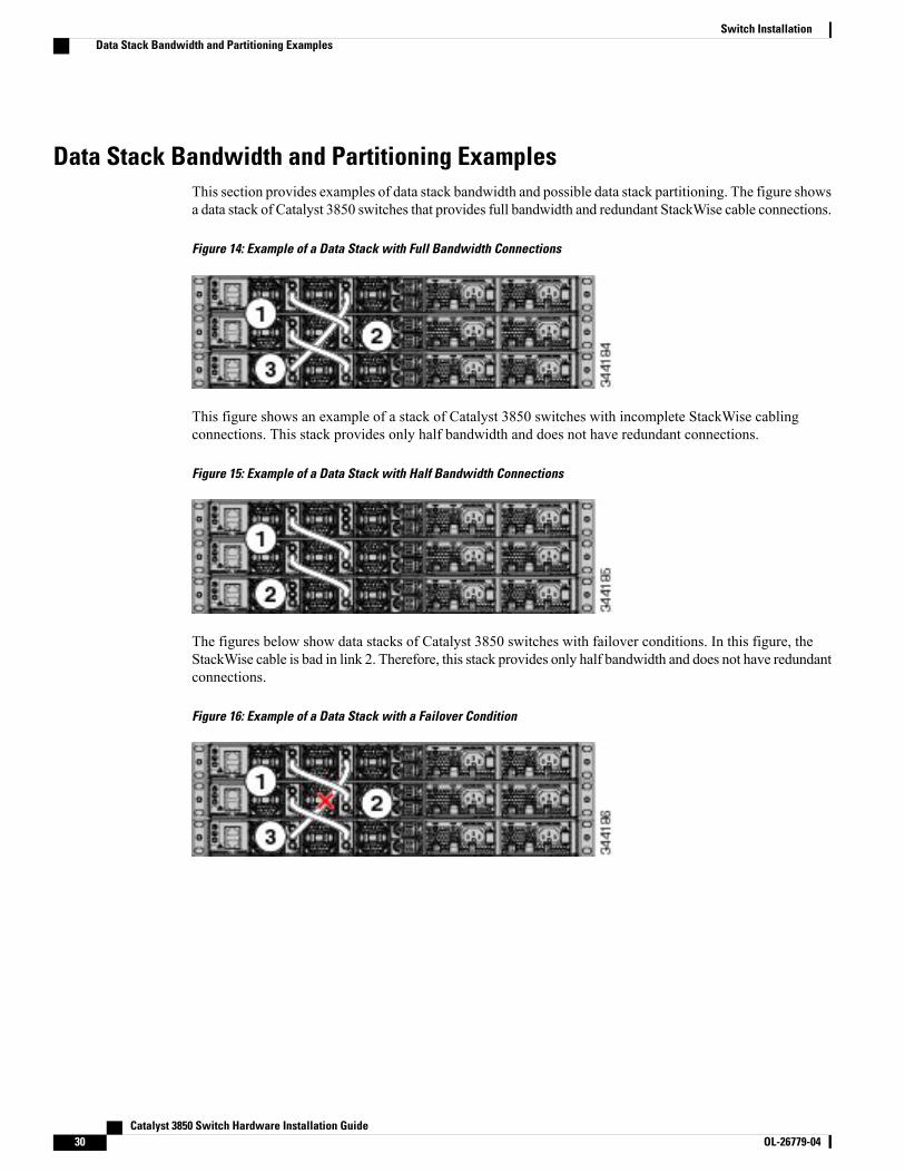
Data Stack Bandwidth and Partitioning ExamplesThis section provides examples of data stack bandwidth and possible data stack partitioning. The figure showsa data stack of Catalyst 3850 switches that provides full bandwidth and redundant StackWise cable connections.
Figure 14: Example of a Data Stack with Full Bandwidth Connections
This figure shows an example of a stack of Catalyst 3850 switches with incomplete StackWise cablingconnections. This stack provides only half bandwidth and does not have redundant connections.
Figure 15: Example of a Data Stack with Half Bandwidth Connections
The figures below show data stacks of Catalyst 3850 switches with failover conditions. In this figure, theStackWise cable is bad in link 2. Therefore, this stack provides only half bandwidth and does not have redundantconnections.
Figure 16: Example of a Data Stack with a Failover Condition
Catalyst 3850 Switch Hardware Installation Guide30 OL-26779-04
Switch InstallationData Stack Bandwidth and Partitioning Examples
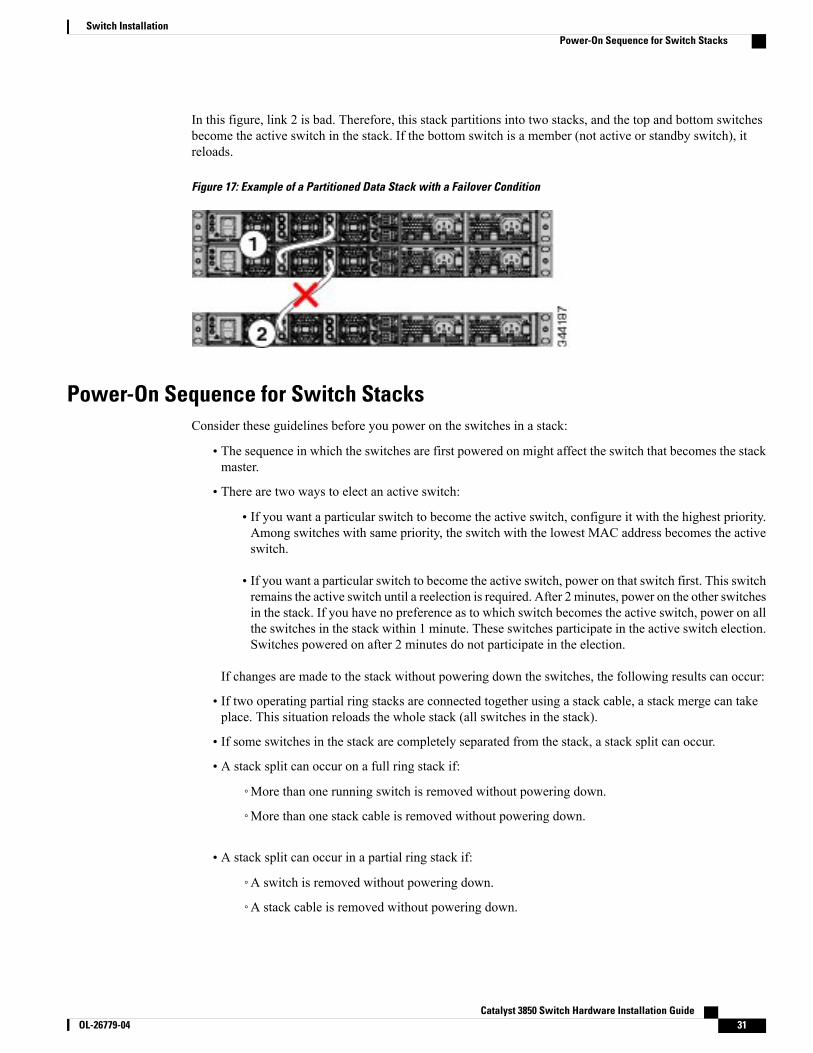
In this figure, link 2 is bad. Therefore, this stack partitions into two stacks, and the top and bottom switchesbecome the active switch in the stack. If the bottom switch is a member (not active or standby switch), itreloads.
Figure 17: Example of a Partitioned Data Stack with a Failover Condition
Power-On Sequence for Switch StacksConsider these guidelines before you power on the switches in a stack:
• The sequence in which the switches are first powered on might affect the switch that becomes the stackmaster.
• There are two ways to elect an active switch:
• If you want a particular switch to become the active switch, configure it with the highest priority.Among switches with same priority, the switch with the lowest MAC address becomes the activeswitch.
• If you want a particular switch to become the active switch, power on that switch first. This switchremains the active switch until a reelection is required. After 2 minutes, power on the other switchesin the stack. If you have no preference as to which switch becomes the active switch, power on allthe switches in the stack within 1 minute. These switches participate in the active switch election.Switches powered on after 2 minutes do not participate in the election.
If changes are made to the stack without powering down the switches, the following results can occur:
• If two operating partial ring stacks are connected together using a stack cable, a stack merge can takeplace. This situation reloads the whole stack (all switches in the stack).
• If some switches in the stack are completely separated from the stack, a stack split can occur.
• A stack split can occur on a full ring stack if:
◦More than one running switch is removed without powering down.
◦More than one stack cable is removed without powering down.
• A stack split can occur in a partial ring stack if:
◦A switch is removed without powering down.
◦A stack cable is removed without powering down.
Catalyst 3850 Switch Hardware Installation Guide OL-26779-04 31
Switch InstallationPower-On Sequence for Switch Stacks
• In a split stack, depending on where the active and standby switches are located, either two stacks mightbe formed (with the standby taking over as the new active switch in the newly formed stack) or all themembers in the newly formed stack might reload.
These results depend on how the switches are connected. You can remove two or more switches from thestack without splitting the stack.
Note
For conditions that can cause a stack reelection or to manually elect the active switch, see the stacking softwareconfiguration guide on Cisco.com at this URL: http://www.cisco.com/go/cat3850_docs.
Planning a StackPower Stack
StackPower Stacking GuidelinesYou can configure a StackPower stack for either power sharing or redundancy. In power-sharing mode, thepower of all the power supplies in the stack is aggregated and distributed among the stack members.
In redundant mode, when the total power budget of the stack is calculated, the wattage of the largest powersupply is not included. That power is held in reserve and used to maintain power to switches and attacheddevices when one power supply fails. Following the failure of a power supply, the StackPower mode becomespower sharing.
Power-sharing mode is the recommended configuration for Catalyst 3850 switches.Note
For general concepts and management procedures for switch power stacks, see the software stackingconfiguration guide on Cisco.com.
Before connecting the switches in a power stack, keep in mind these guidelines:
• Size of the switch and any optional power supply module. The 1100-W power-supply module is 1.5inches (3.81 cm) longer than the other modules, and with the attached cable retention clip, it extends 3inches (7.62 cm) from the switch chassis. Stacking switches with the same power-supply modulestogether makes it easier to cable the switches. For switch dimensions, see Appendix A, “TechnicalSpecifications.”
• Length of cable. Depending on the configurations that you have, you might need different-sized cables.If you do not specify the length of the StackPower cable, the 0.3 meter cable is supplied. If you needthe 1.5 meter cable, you can order it from your Cisco supplier. For cable part numbers, see StackPowerConnector, on page 23. The StackPower Cabling Configurations, on page 33 provides examples ofrecommended configurations.
• For rack-mounted switch stacks that are members of a data stack and a StackPower stack, see SwitchStacking and Power Stacking Guidelines, on page 28.
Catalyst 3850 Switch Hardware Installation Guide32 OL-26779-04
Switch InstallationPlanning a StackPower Stack
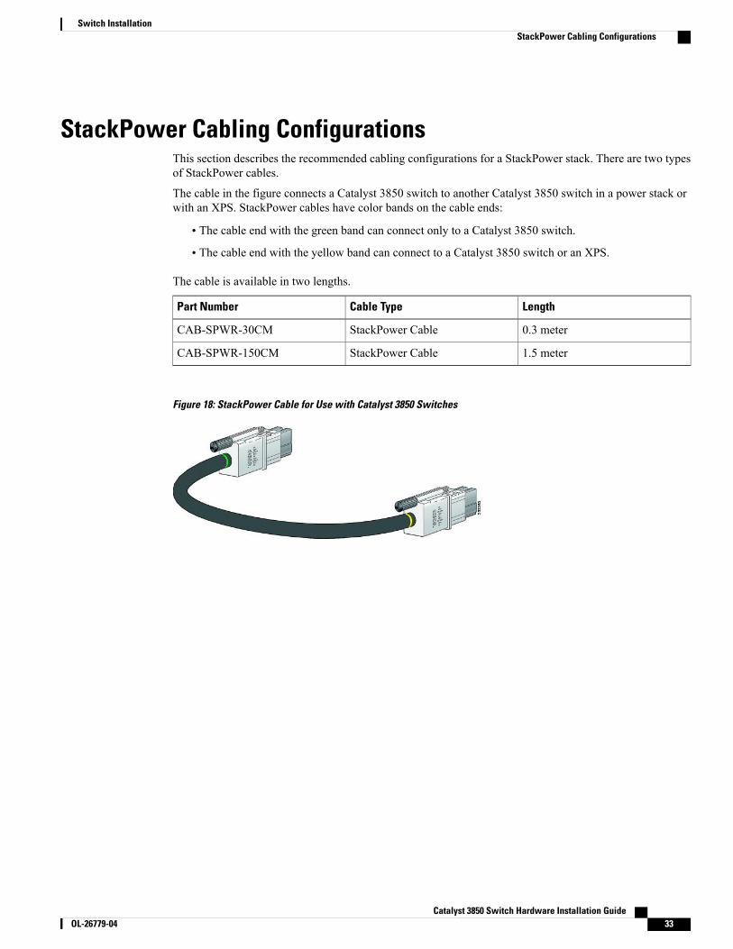
StackPower Cabling ConfigurationsThis section describes the recommended cabling configurations for a StackPower stack. There are two typesof StackPower cables.
The cable in the figure connects a Catalyst 3850 switch to another Catalyst 3850 switch in a power stack orwith an XPS. StackPower cables have color bands on the cable ends:
• The cable end with the green band can connect only to a Catalyst 3850 switch.
• The cable end with the yellow band can connect to a Catalyst 3850 switch or an XPS.
The cable is available in two lengths.
LengthCable TypePart Number
0.3 meterStackPower CableCAB-SPWR-30CM
1.5 meterStackPower CableCAB-SPWR-150CM
Figure 18: StackPower Cable for Use with Catalyst 3850 Switches
Catalyst 3850 Switch Hardware Installation Guide OL-26779-04 33
Switch InstallationStackPower Cabling Configurations
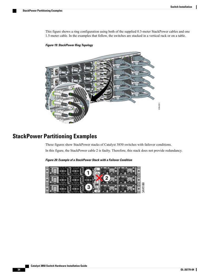
This figure shows a ring configuration using both of the supplied 0.3-meter StackPower cables and one1.5-meter cable. In the examples that follow, the switches are stacked in a vertical rack or on a table.
Figure 19: StackPower Ring Topology
StackPower Partitioning ExamplesThese figures show StackPower stacks of Catalyst 3850 switches with failover conditions.
In this figure, the StackPower cable 2 is faulty. Therefore, this stack does not provide redundancy.
Figure 20: Example of a StackPower Stack with a Failover Condition
Catalyst 3850 Switch Hardware Installation Guide34 OL-26779-04
Switch InstallationStackPower Partitioning Examples
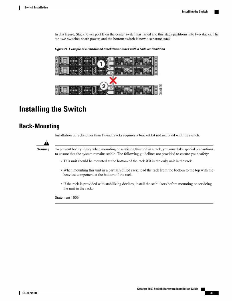
In this figure, StackPower port B on the center switch has failed and this stack partitions into two stacks. Thetop two switches share power, and the bottom switch is now a separate stack.
Figure 21: Example of a Partitioned StackPower Stack with a Failover Condition
Installing the Switch
Rack-MountingInstallation in racks other than 19-inch racks requires a bracket kit not included with the switch.
To prevent bodily injury when mounting or servicing this unit in a rack, you must take special precautionsto ensure that the system remains stable. The following guidelines are provided to ensure your safety:
Warning
• This unit should be mounted at the bottom of the rack if it is the only unit in the rack.
•When mounting this unit in a partially filled rack, load the rack from the bottom to the top with theheaviest component at the bottom of the rack.
• If the rack is provided with stabilizing devices, install the stabilizers before mounting or servicingthe unit in the rack.
Statement 1006
Catalyst 3850 Switch Hardware Installation Guide OL-26779-04 35
Switch InstallationInstalling the Switch
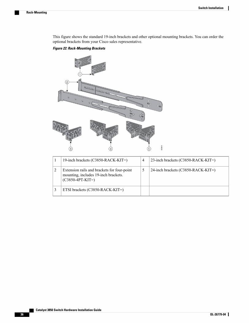
This figure shows the standard 19-inch brackets and other optional mounting brackets. You can order theoptional brackets from your Cisco sales representative.Figure 22: Rack-Mounting Brackets
23-inch brackets (C3850-RACK-KIT=)419-inch brackets (C3850-RACK-KIT=)1
24-inch brackets (C3850-RACK-KIT=)5Extension rails and brackets for four-pointmounting, includes 19-inch brackets.(C3850-4PT-KIT=)
2
ETSI brackets (C3850-RACK-KIT=)3
Catalyst 3850 Switch Hardware Installation Guide36 OL-26779-04
Switch InstallationRack-Mounting
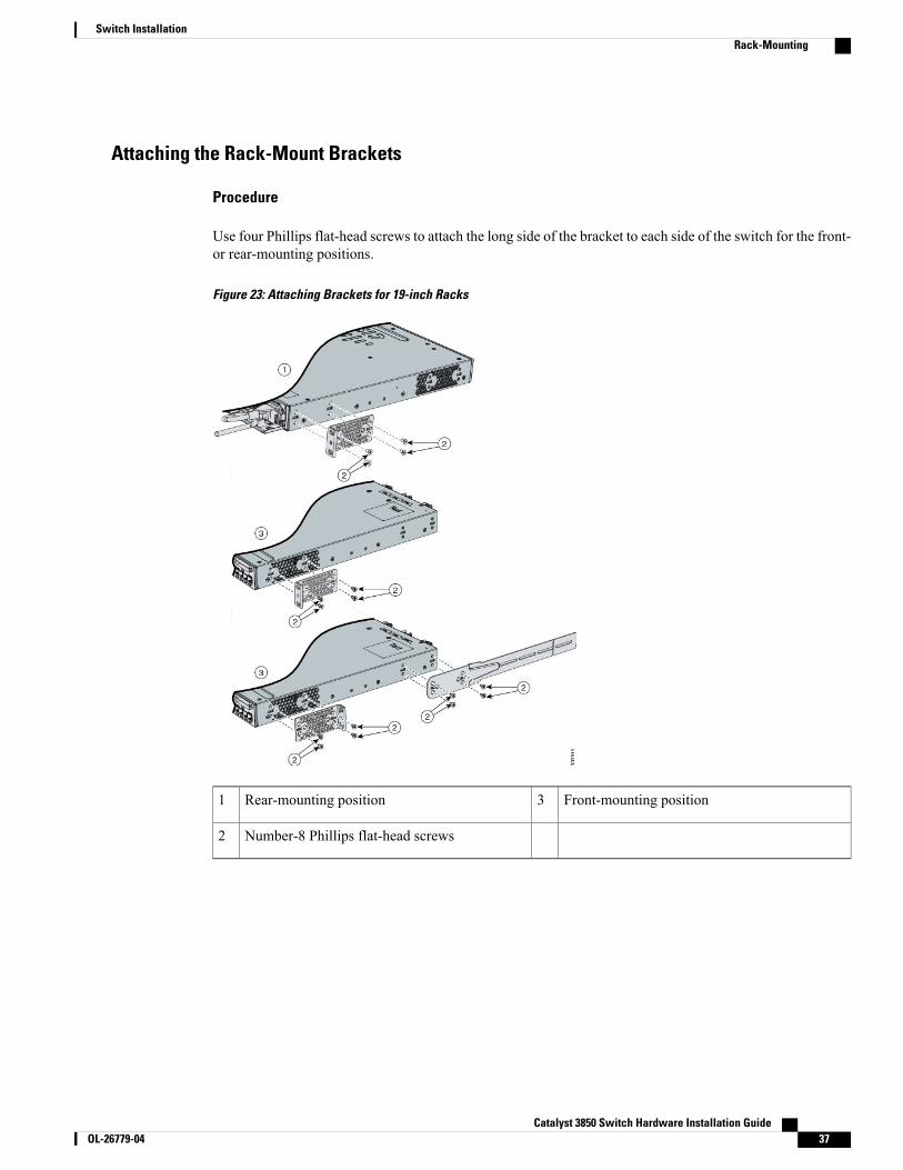
Attaching the Rack-Mount Brackets
Procedure
Use four Phillips flat-head screws to attach the long side of the bracket to each side of the switch for the front-or rear-mounting positions.
Figure 23: Attaching Brackets for 19-inch Racks
Front-mounting position3Rear-mounting position1
Number-8 Phillips flat-head screws2
Catalyst 3850 Switch Hardware Installation Guide OL-26779-04 37
Switch InstallationRack-Mounting
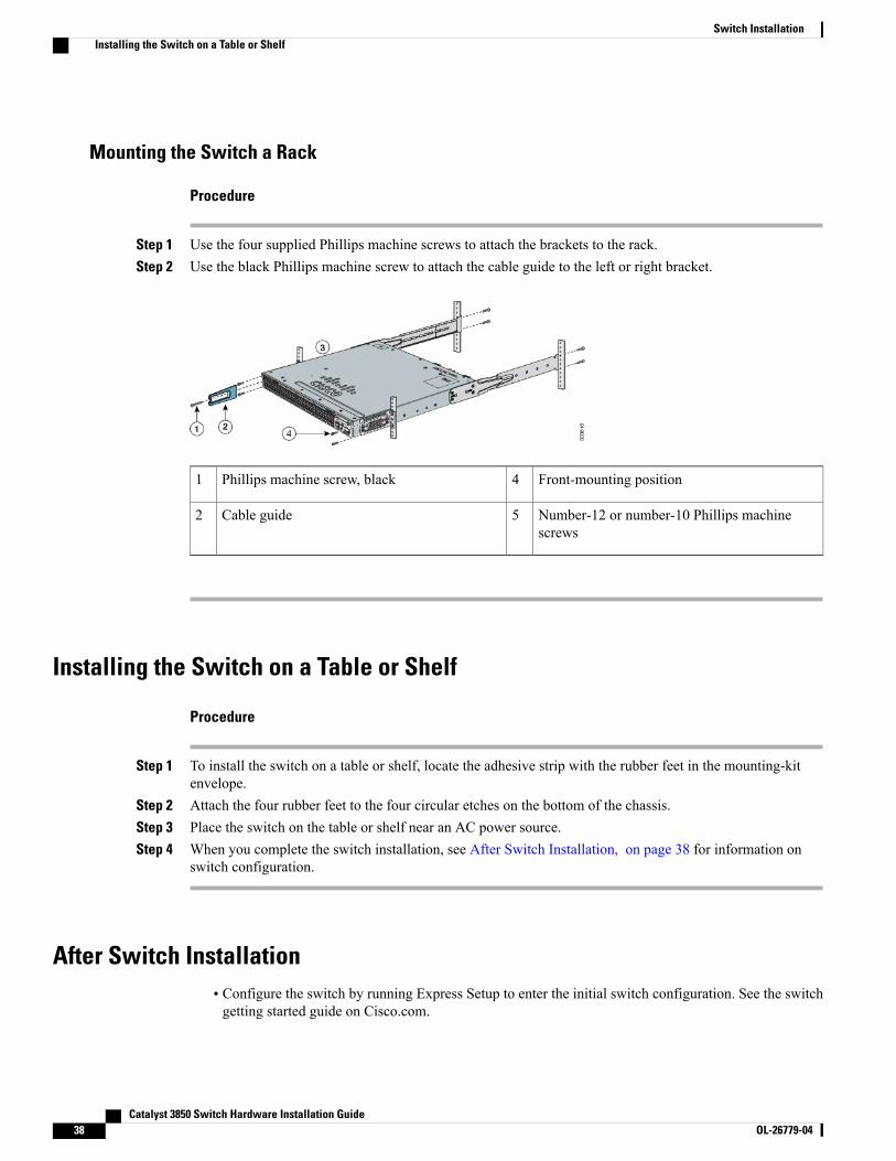
Mounting the Switch a Rack
Procedure
Step 1 Use the four supplied Phillips machine screws to attach the brackets to the rack.Step 2 Use the black Phillips machine screw to attach the cable guide to the left or right bracket.
Front-mounting position4Phillips machine screw, black1
Number-12 or number-10 Phillips machinescrews
5Cable guide2
Installing the Switch on a Table or Shelf
Procedure
Step 1 To install the switch on a table or shelf, locate the adhesive strip with the rubber feet in the mounting-kitenvelope.
Step 2 Attach the four rubber feet to the four circular etches on the bottom of the chassis.Step 3 Place the switch on the table or shelf near an AC power source.Step 4 When you complete the switch installation, see After Switch Installation, on page 38 for information on
switch configuration.
After Switch Installation• Configure the switch by running Express Setup to enter the initial switch configuration. See the switchgetting started guide on Cisco.com.
Catalyst 3850 Switch Hardware Installation Guide38 OL-26779-04
Switch InstallationInstalling the Switch on a Table or Shelf
• Use the CLI setup program to enter the initial switch configuration.
• Connect to the stack ports.
• Connect to the front-panel ports.
Connecting to the StackWise PortsBefore You Begin
Before connecting the StackWise cables, review the Planning a Switch Data Stack, on page 28. Always usea Cisco-approved StackWise cable to connect the switches.
Catalyst 3850 Switch Hardware Installation Guide OL-26779-04 39
Switch InstallationConnecting to the StackWise Ports
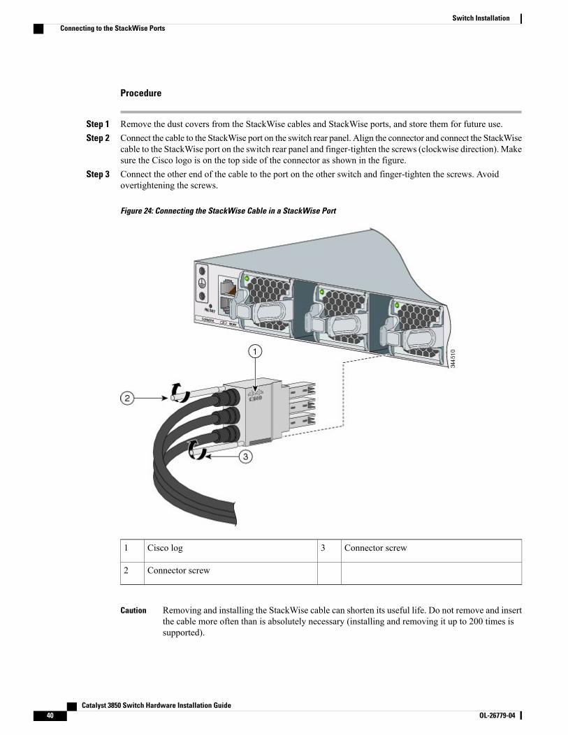
Procedure
Step 1 Remove the dust covers from the StackWise cables and StackWise ports, and store them for future use.Step 2 Connect the cable to the StackWise port on the switch rear panel. Align the connector and connect the StackWise
cable to the StackWise port on the switch rear panel and finger-tighten the screws (clockwise direction). Makesure the Cisco logo is on the top side of the connector as shown in the figure.
Step 3 Connect the other end of the cable to the port on the other switch and finger-tighten the screws. Avoidovertightening the screws.
Figure 24: Connecting the StackWise Cable in a StackWise Port
Connector screw3Cisco log1
Connector screw2
Removing and installing the StackWise cable can shorten its useful life. Do not remove and insertthe cable more often than is absolutely necessary (installing and removing it up to 200 times issupported).
Caution
Catalyst 3850 Switch Hardware Installation Guide40 OL-26779-04
Switch InstallationConnecting to the StackWise Ports
When you need to remove the StackWise cable from the connector, make sure to fully unscrew the correctscrews. When the connectors are not being used, replace the dust covers.
Connecting to the StackPower PortsBefore You Begin
Before connecting the StackPower cables, review Planning a Switch Data Stack, on page 28. Always use aCisco-approved StackWise cable to connect the switches. To prevent misconfiguration, the StackPower portson the switch are keyed and have colored bands that match the keying and bands on the StackPower cableconnectors.
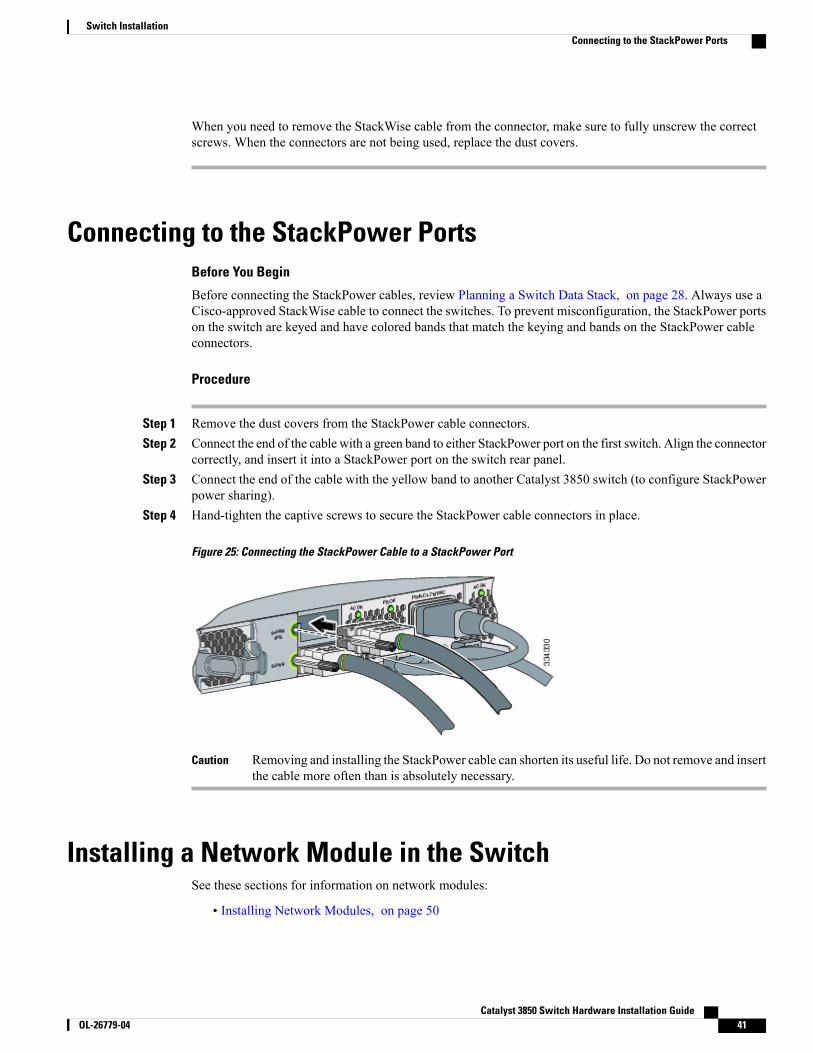
Procedure
Step 1 Remove the dust covers from the StackPower cable connectors.Step 2 Connect the end of the cable with a green band to either StackPower port on the first switch. Align the connector
correctly, and insert it into a StackPower port on the switch rear panel.Step 3 Connect the end of the cable with the yellow band to another Catalyst 3850 switch (to configure StackPower
power sharing).Step 4 Hand-tighten the captive screws to secure the StackPower cable connectors in place.
Figure 25: Connecting the StackPower Cable to a StackPower Port
Removing and installing the StackPower cable can shorten its useful life. Do not remove and insertthe cable more often than is absolutely necessary.
Caution
Installing a Network Module in the SwitchSee these sections for information on network modules:
• Installing Network Modules, on page 50
Catalyst 3850 Switch Hardware Installation Guide OL-26779-04 41
Switch InstallationConnecting to the StackPower Ports
Installing and Removing SFP and SFP+ ModulesSee these sections for information on SFPs and SFP+:
• Installing SFP and SFP+ Modules, on page 54
• Removing SFP and SFP+ Modules, on page 55
Connecting Devices to the Ethernet Ports• 10/100/1000 Port Connections, on page 42
• PoE+ and Cisco UPOE Port Connections, on page 43
10/100/1000 Port ConnectionsThe switch 10/100/1000 port configuration changes to operate at the speed of the attached device. If theattached ports do not support autonegotiation, you can manually set the speed and duplex parameters.Connecting devices that do not autonegotiate or that have the speed and duplex parameters manually set canreduce performance or result in no linkage.
To maximize performance, choose one of these methods for configuring the Ethernet ports:
• Let the ports autonegotiate both speed and duplex.
• Set the interface speed and duplex parameters on both ends of the connection.
Be careful when connecting a “snagless” Ethernet cable to port 1 on a 48-port switch. The protective bootof the cable might inadvertently press the Mode button, which could cause the switch to erase its startupconfiguration and reboot. See this field notice for more information: http://www.cisco.com/c/en/us/support/docs/field-notices/636/fn63697.htmlThis issue does not occur if you are using Cisco IOS XE Release 3E or later releases.
Note
Auto-MDIX ConnectionsThe autonegotiation and the auto-MDIX features are enabled by default on the switch.
With autonegotiation, the switch port configurations change to operate at the speed of the attached device. Ifthe attached device does not support autonegotiation, you can manually set the switch interface speed andduplex parameters.
With auto-MDIX, the switch detects the required cable type for copper Ethernet connections and configuresthe interface accordingly.
If auto-MDIX is disabled, use the guidelines in this table to select the correct cable.
Catalyst 3850 Switch Hardware Installation Guide42 OL-26779-04
Switch InstallationInstalling and Removing SFP and SFP+ Modules
Table 19: Recommended Ethernet Cables (When Auto-MDIX is Disabled)
Straight-Through CableCrossover Cable13Device
NoYesSwitch to switch
NoYesSwitch to hub
YesNoSwitch to computer or server
YesNoSwitch to router
YesNoSwitch to IP phone
13 100BASE-TX and 1000BASE-T traffic requires twisted four-pair, Category 5, Category 5e, or Category 6 cable. 10BASE-T traffic can use Category 3 orCategory 4 cable.
PoE+ and Cisco UPOE Port ConnectionsThe 10/100/1000 PoE+ and Cisco UPOE ports have the same autonegotiation settings and cabling requirementsthat are described in the 10/100/1000 Port Connections, on page 42. These ports can provide PoE, PoE+, orCisco UPOE inline power.
Be careful when connecting a “snagless” Ethernet cable to port 1 on a 48-port switch. The protective bootof the cable might inadvertently press the Mode button, which might cause the switch to erase its startupconfiguration and reboot. See this field notice for more information: http://www.cisco.com/c/en/us/support/docs/field-notices/636/fn63697.htmlThis issue does not occur if you are using Cisco IOS XE Release 3E or later releases.
Note
PoE inline power supports devices compliant with the IEEE 802.3af standard, as well as prestandard CiscoIP Phones and Cisco Aironet Access Points. Each port can deliver up to 15.4 W of PoE. PoE+ inline powersupports devices compliant with the IEEE 802.3at standard, by delivering up to 30W of PoE+ power per portto all switch ports.
See Power Supply Modules, on page 19 for the power supply modules required to support PoE, PoE+, andCisco UPOE on 24- and 48-port switches.
Voltages that present a shock hazard may exist on Power over Ethernet (PoE) circuits if interconnectionsare made using uninsulated exposed metal contacts, conductors, or terminals. Avoid using suchinterconnection methods, unless the exposed metal parts are located within a restricted access locationand users and service people who are authorized within the restricted access location are made aware ofthe hazard. A restricted access area can be accessed only through the use of a special tool, lock and keyor other means of security. Statement 1072
Warning
Catalyst 3850 Switch Hardware Installation Guide OL-26779-04 43
Switch InstallationPoE+ and Cisco UPOE Port Connections
Voice over IP (VoIP) service and the emergency calling service do not function if power fails or is disrupted.After power is restored, you might have to reset or reconfigure equipment to regain access to VoIP andthe emergency calling service. In the USA, this emergency number is 911. You need to be aware of theemergency number in your country. Statement 371
Warning
Category 5e and Category 6 cables can store high levels of static electricity. Always ground the cables toa suitable and safe earth ground before connecting them to the switch or other devices.
Caution
Noncompliant cabling or powered devices can cause a PoE port fault. Use only standard-compliant cablingto connect Cisco prestandard IP Phones and wireless access points, IEEE 802.3af, or 802.3at(PoE+)-compliant devices. You must remove any cable or device that causes a PoE fault.
Caution
Where to Go NextIf the default configuration is satisfactory, the switch does not need further configuration. You can use anyof these management options to change the default configuration:
• Start the Network Assistant application, which is described in the getting started guide. Through thisGUI, you can configure and monitor a switch cluster or an individual switch.
• Use the CLI to configure the switch as a member of a cluster or as an individual switch from the console.
• Use the Cisco Prime Infrastructure application.
Catalyst 3850 Switch Hardware Installation Guide44 OL-26779-04
Switch InstallationWhere to Go Next
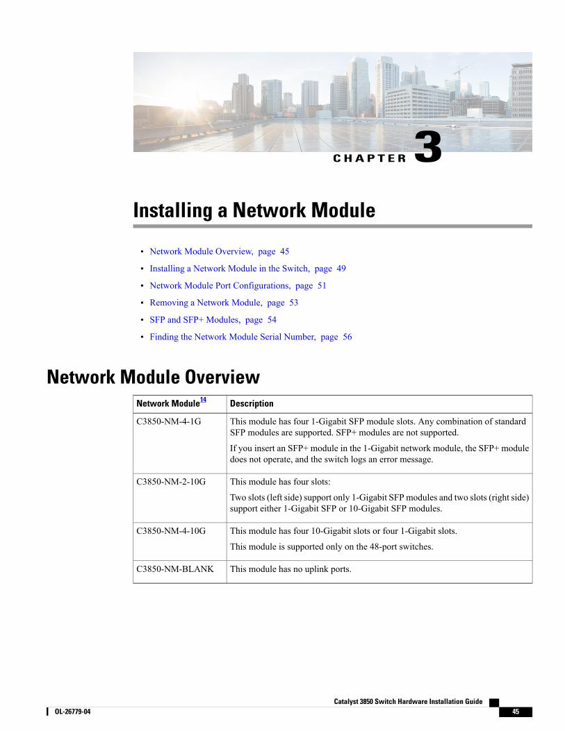
C H A P T E R 3Installing a Network Module
• Network Module Overview, page 45
• Installing a Network Module in the Switch, page 49
• Network Module Port Configurations, page 51
• Removing a Network Module, page 53
• SFP and SFP+ Modules, page 54
• Finding the Network Module Serial Number, page 56
Network Module OverviewDescriptionNetwork Module14
This module has four 1-Gigabit SFP module slots. Any combination of standardSFP modules are supported. SFP+ modules are not supported.
If you insert an SFP+ module in the 1-Gigabit network module, the SFP+ moduledoes not operate, and the switch logs an error message.
C3850-NM-4-1G
This module has four slots:
Two slots (left side) support only 1-Gigabit SFP modules and two slots (right side)support either 1-Gigabit SFP or 10-Gigabit SFP modules.
C3850-NM-2-10G
This module has four 10-Gigabit slots or four 1-Gigabit slots.
This module is supported only on the 48-port switches.
C3850-NM-4-10G
This module has no uplink ports.C3850-NM-BLANK
Catalyst 3850 Switch Hardware Installation Guide OL-26779-04 45
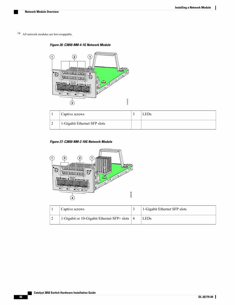
14 All network modules are hot-swappable.
Figure 26: C3850-NM-4-1G Network Module
LEDs3Captive screws1
1-Gigabit Ethernet SFP slots2
Figure 27: C3850-NM-2-10G Network Module
1-Gigabit Ethernet SFP slots3Captive screws1
LEDs41-Gigabit or 10-Gigabit Ethernet SFP+ slots2
Catalyst 3850 Switch Hardware Installation Guide46 OL-26779-04
Installing a Network ModuleNetwork Module Overview
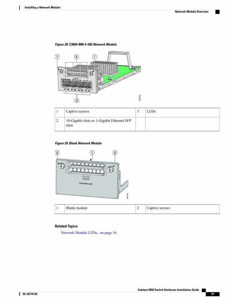
Figure 28: C3850-NM-4-10G Network Module
LEDs3Captive screws1
10-Gigabit slots or 1-Gigabit Ethernet SFPslots
2
Figure 29: Blank Network Module
Captive screws2Blank module1
Related Topics
Network Module LEDs, on page 16
Catalyst 3850 Switch Hardware Installation Guide OL-26779-04 47
Installing a Network ModuleNetwork Module Overview
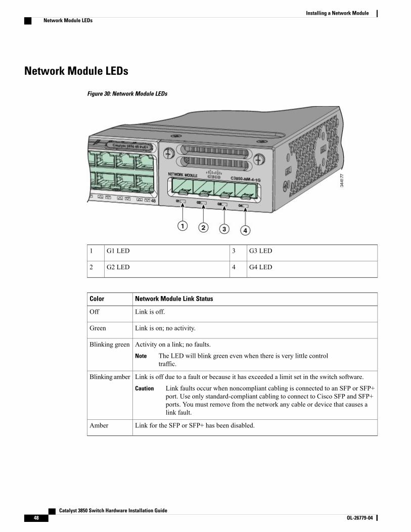
Network Module LEDs
Figure 30: Network Module LEDs
G3 LED3G1 LED1
G4 LED4G2 LED2
Network Module Link StatusColor
Link is off.Off
Link is on; no activity.Green
Activity on a link; no faults.
The LED will blink green even when there is very little controltraffic.
Note
Blinking green
Link is off due to a fault or because it has exceeded a limit set in the switch software.
Link faults occur when noncompliant cabling is connected to an SFP or SFP+port. Use only standard-compliant cabling to connect to Cisco SFP and SFP+ports. You must remove from the network any cable or device that causes alink fault.
Caution
Blinking amber
Link for the SFP or SFP+ has been disabled.Amber
Catalyst 3850 Switch Hardware Installation Guide48 OL-26779-04
Installing a Network ModuleNetwork Module LEDs
Installing a Network Module in the Switch
Safety WarningsThis section includes the installation cautions and warnings. Translations of the safety warnings appear in theRegulatory Compliance and Safety Information for the Catalyst 3850 Switches on Cisco.com: http://www.cisco.com/go/cat3850_hw
Read this section before you install a network module.
Proper ESD protection is required whenever you handle equipment. Installation andmaintenance personnelshould be properly grounded by grounding straps to eliminate the risk of ESD damage to the equipment.Equipment is subject to ESD damage whenever you remove it.
Caution
Only trained and qualified personnel should be allowed to install, replace, or service this equipment.Statement 1030
Warning
Do not reach into a vacant slot or chassis while you install or remove a module. Exposed circuitry couldconstitute an energy hazard. Statement 206
Warning
Equipment That You Need• Ratcheting torque screwdriver with a number-2 Phillips head that exerts up to 15 pound-force inches(lbf-in.) of pressure.
• Panduit crimping tool with optional controlled-cycle mechanism (model CT-720, CT-920, CT-920CH,CT-930, or CT-940CH).
•Wire-stripping tools.
• 12-gauge copper ground wire (insulated or not) for the single-hole ground connection.
• 8-gauge copper ground wire (insulated or not) for the dual-hole ground connection.
• Dual-hole ground lug and two screws (included in the DC power supply accessory kit) and single-holeground lug and screw (included in the switch accessory kit). The dual-hole lug is required for thegrounding of the switch in a NEBS installation where the DC supply is the only NEBS compliant powersupply option.
• Four leads of 14-gauge copper wire.
• Four fork-type terminals from the DC power supply accessory kit. The terminals must be the propersize for M3 screws in a Dinkle DT-35-B25-style terminal block.
Catalyst 3850 Switch Hardware Installation Guide OL-26779-04 49
Installing a Network ModuleInstalling a Network Module in the Switch
Installing Network Modules
The switch can operate without a network module, but a blank module (with no ports or SFP slots) isavailable and should be installed when uplink ports are not required.
Note
The switch generates logs when you insert or remove a network module with SFP slots.Note
Use only supported networkmodules and SFP or SFP+modules. Eachmodule has an internal serial EEPROMthat is encoded with security information. For information about supported SFP modules, see SFP and SFP+Modules, on page 7.
The network module is hot-swappable. If you remove a module, replace it with another network module ora blank module.
The switch complies with EMC, safety, and thermal specifications when a network module is present. Ifno uplink ports are required, install a blank network module.
Note
Before You Begin
When installing network modules, observe these precautions:
• Do not remove the EMC plug from the 10-Gigabit Ethernet slot until you install an SFP or SFP+module.Either a module or a dust plug must be in the slot at all times.
• Do not remove the dust plugs from the fiber-optic SFP modules or the rubber caps from the fiber-opticcable until you connect the cable. The plugs and caps protect the module ports and cables fromcontamination and ambient light.
• Removing and installing a networkmodule can shorten its useful life. Do not remove and insert a networkmodule more often than is necessary.
• To prevent ESD damage, follow your normal board and component handling procedures when connectingcables to the switch and other devices.
Procedure
Step 1 Attach an ESD-preventive wrist strap to your wrist and to an earth ground surface.Step 2 Remove the module from the protective packaging.Step 3 Remove the 10-Gigabit Ethernet module slot EMC plug, and save it.
Verify the correct orientation of your module before installing it. Incorrect installation can damagethe module.
Caution
Do not install the network module with connected cables or installed SFPmodules. Always removeany cables and modules before you install the network module.
Caution
Amodule interfacemight become error-disabledwhen a networkmodule with connected fiber-opticcables is installed or removed. If an interface is error-disabled, you can reenable the interface byusing the shutdown and no shutdown interface configuration commands.
Caution
Catalyst 3850 Switch Hardware Installation Guide50 OL-26779-04
Installing a Network ModuleInstalling Network Modules
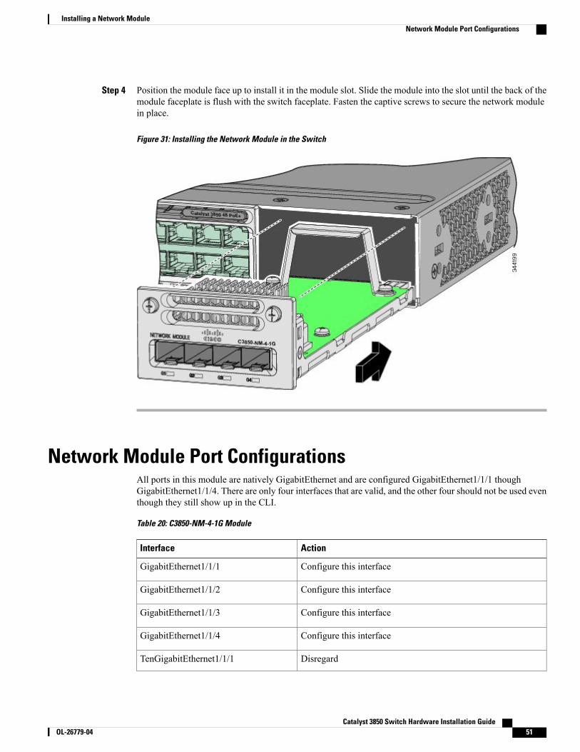
Step 4 Position the module face up to install it in the module slot. Slide the module into the slot until the back of themodule faceplate is flush with the switch faceplate. Fasten the captive screws to secure the network modulein place.
Figure 31: Installing the Network Module in the Switch
Network Module Port ConfigurationsAll ports in this module are natively GigabitEthernet and are configured GigabitEthernet1/1/1 thoughGigabitEthernet1/1/4. There are only four interfaces that are valid, and the other four should not be used eventhough they still show up in the CLI.
Table 20: C3850-NM-4-1G Module
ActionInterface
Configure this interfaceGigabitEthernet1/1/1
Configure this interfaceGigabitEthernet1/1/2
Configure this interfaceGigabitEthernet1/1/3
Configure this interfaceGigabitEthernet1/1/4
DisregardTenGigabitEthernet1/1/1
Catalyst 3850 Switch Hardware Installation Guide OL-26779-04 51
Installing a Network ModuleNetwork Module Port Configurations
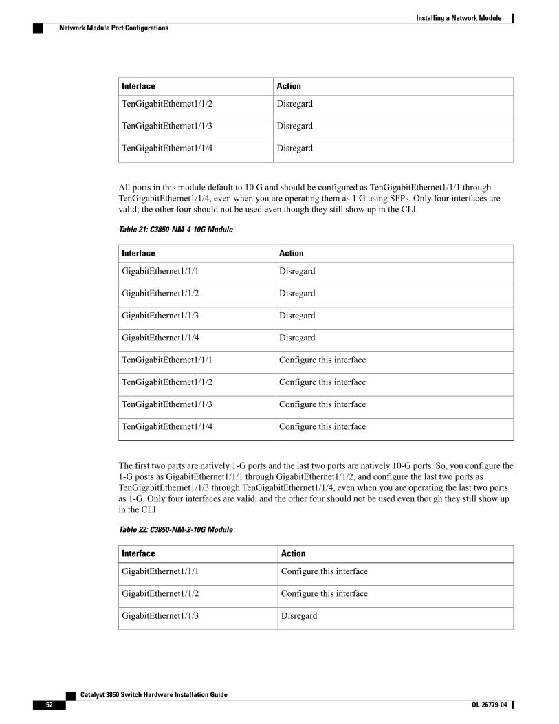
ActionInterface
DisregardTenGigabitEthernet1/1/2
DisregardTenGigabitEthernet1/1/3
DisregardTenGigabitEthernet1/1/4
All ports in this module default to 10 G and should be configured as TenGigabitEthernet1/1/1 throughTenGigabitEthernet1/1/4, even when you are operating them as 1 G using SFPs. Only four interfaces arevalid; the other four should not be used even though they still show up in the CLI.
Table 21: C3850-NM-4-10G Module
ActionInterface
DisregardGigabitEthernet1/1/1
DisregardGigabitEthernet1/1/2
DisregardGigabitEthernet1/1/3
DisregardGigabitEthernet1/1/4
Configure this interfaceTenGigabitEthernet1/1/1
Configure this interfaceTenGigabitEthernet1/1/2
Configure this interfaceTenGigabitEthernet1/1/3
Configure this interfaceTenGigabitEthernet1/1/4
The first two parts are natively 1-G ports and the last two ports are natively 10-G ports. So, you configure the1-G posts as GigabitEthernet1/1/1 through GigabitEthernet1/1/2, and configure the last two ports asTenGigabitEthernet1/1/3 through TenGigabitEthernet1/1/4, even when you are operating the last two portsas 1-G. Only four interfaces are valid, and the other four should not be used even though they still show upin the CLI.
Table 22: C3850-NM-2-10G Module
ActionInterface
Configure this interfaceGigabitEthernet1/1/1
Configure this interfaceGigabitEthernet1/1/2
DisregardGigabitEthernet1/1/3
Catalyst 3850 Switch Hardware Installation Guide52 OL-26779-04
Installing a Network ModuleNetwork Module Port Configurations
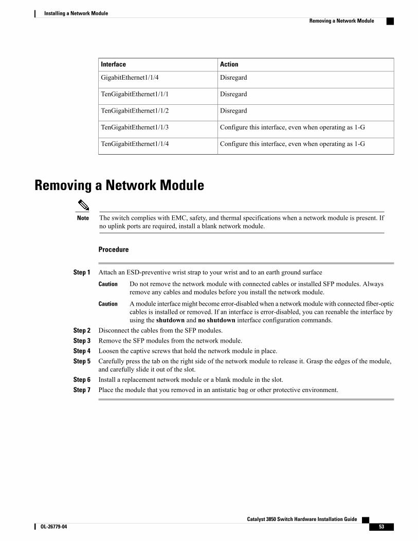
ActionInterface
DisregardGigabitEthernet1/1/4
DisregardTenGigabitEthernet1/1/1
DisregardTenGigabitEthernet1/1/2
Configure this interface, even when operating as 1-GTenGigabitEthernet1/1/3
Configure this interface, even when operating as 1-GTenGigabitEthernet1/1/4
Removing a Network Module
The switch complies with EMC, safety, and thermal specifications when a network module is present. Ifno uplink ports are required, install a blank network module.
Note
Procedure
Step 1 Attach an ESD-preventive wrist strap to your wrist and to an earth ground surface
Do not remove the network module with connected cables or installed SFP modules. Alwaysremove any cables and modules before you install the network module.
Caution
Amodule interfacemight become error-disabledwhen a networkmodule with connected fiber-opticcables is installed or removed. If an interface is error-disabled, you can reenable the interface byusing the shutdown and no shutdown interface configuration commands.
Caution
Step 2 Disconnect the cables from the SFP modules.Step 3 Remove the SFP modules from the network module.Step 4 Loosen the captive screws that hold the network module in place.Step 5 Carefully press the tab on the right side of the network module to release it. Grasp the edges of the module,
and carefully slide it out of the slot.Step 6 Install a replacement network module or a blank module in the slot.Step 7 Place the module that you removed in an antistatic bag or other protective environment.
Catalyst 3850 Switch Hardware Installation Guide OL-26779-04 53
Installing a Network ModuleRemoving a Network Module
SFP and SFP+ Modules
Installing SFP and SFP+ Modules
Before You Begin
You must have an installed network module to use SFP and SFP+ modules (except for the Catalyst 3850-12Sand 3850-24S). The downlink ports on the Catalyst 3850-12S and 3850-24S support standard SFP modules.
See the switch release notes on Cisco.com for the list of supported SFP and SFP+modules. Use only supportedSFP modules on the switch. For the latest information about supported SFP and SFP+ modules, refer to theCisco TransceiverModules Compatibility Information at http://www.cisco.com/en/US/products/hw/modules/ps5455/products_device_support_tables_list.html
For information about installing, removing, cabling, and troubleshooting SFP modules, see the moduledocumentation that shipped with your device.
Observe these precautions:
Class 1 laser product. Statement 1008Warning
• Do not remove the dust plugs from the SFP modules or the rubber caps from the fiber-optic cable untilyou are ready to connect the cable. The plugs and caps protect the module ports and cables fromcontamination and ambient light.
• Removing and installing an SFP module can shorten its useful life. Do not remove and insert any SFPmodule more often than is necessary.
• To prevent ESD damage, follow your normal board and component handling procedures when connectingcables to the switch and other devices.
Procedure
Step 1 Attach an ESD-preventive wrist strap to your wrist and to an earth ground surface.Step 2 Find the send (TX) and receive (RX) markings that identify the top of the SFP module.
Catalyst 3850 Switch Hardware Installation Guide54 OL-26779-04
Installing a Network ModuleSFP and SFP+ Modules
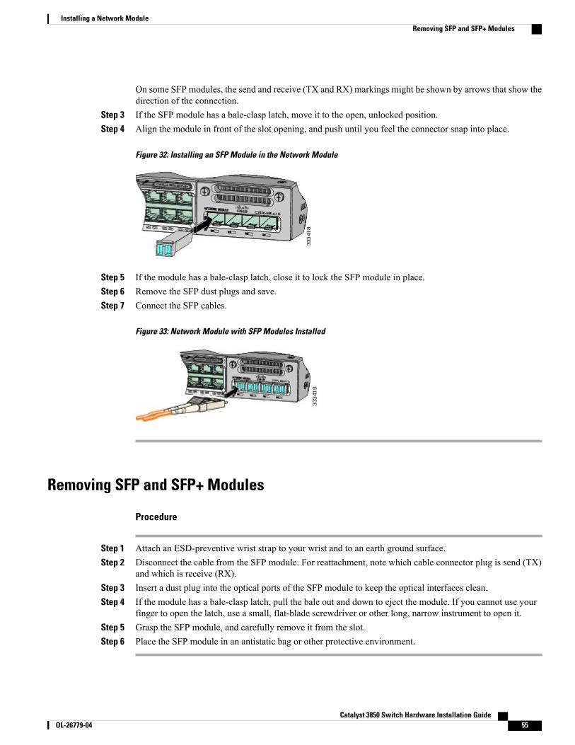
On some SFP modules, the send and receive (TX and RX) markings might be shown by arrows that show thedirection of the connection.
Step 3 If the SFP module has a bale-clasp latch, move it to the open, unlocked position.Step 4 Align the module in front of the slot opening, and push until you feel the connector snap into place.
Figure 32: Installing an SFP Module in the Network Module
Step 5 If the module has a bale-clasp latch, close it to lock the SFP module in place.Step 6 Remove the SFP dust plugs and save.Step 7 Connect the SFP cables.
Figure 33: Network Module with SFP Modules Installed
Removing SFP and SFP+ Modules
Procedure
Step 1 Attach an ESD-preventive wrist strap to your wrist and to an earth ground surface.Step 2 Disconnect the cable from the SFP module. For reattachment, note which cable connector plug is send (TX)
and which is receive (RX).Step 3 Insert a dust plug into the optical ports of the SFP module to keep the optical interfaces clean.Step 4 If the module has a bale-clasp latch, pull the bale out and down to eject the module. If you cannot use your
finger to open the latch, use a small, flat-blade screwdriver or other long, narrow instrument to open it.Step 5 Grasp the SFP module, and carefully remove it from the slot.Step 6 Place the SFP module in an antistatic bag or other protective environment.
Catalyst 3850 Switch Hardware Installation Guide OL-26779-04 55
Installing a Network ModuleRemoving SFP and SFP+ Modules
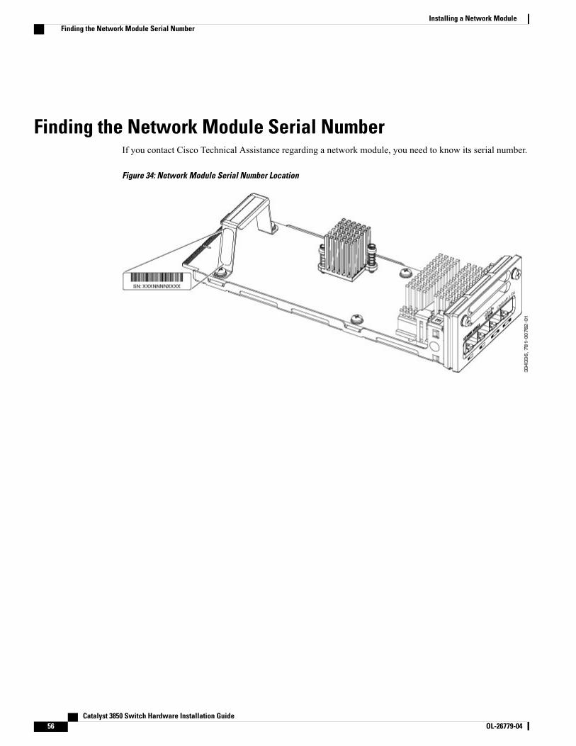
Finding the Network Module Serial NumberIf you contact Cisco Technical Assistance regarding a network module, you need to know its serial number.
Figure 34: Network Module Serial Number Location
Catalyst 3850 Switch Hardware Installation Guide56 OL-26779-04
Installing a Network ModuleFinding the Network Module Serial Number
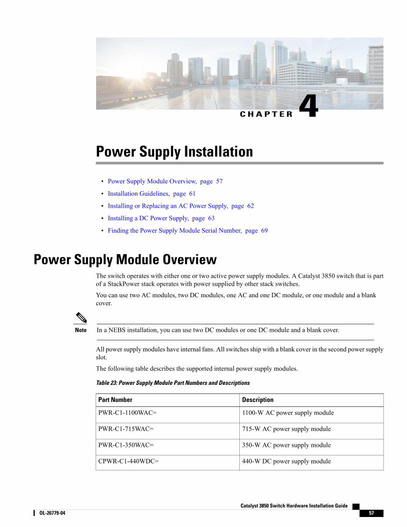
C H A P T E R 4Power Supply Installation
• Power Supply Module Overview, page 57
• Installation Guidelines, page 61
• Installing or Replacing an AC Power Supply, page 62
• Installing a DC Power Supply, page 63
• Finding the Power Supply Module Serial Number, page 69
Power Supply Module OverviewThe switch operates with either one or two active power supply modules. A Catalyst 3850 switch that is partof a StackPower stack operates with power supplied by other stack switches.
You can use two AC modules, two DC modules, one AC and one DC module, or one module and a blankcover.
In a NEBS installation, you can use two DC modules or one DC module and a blank cover.Note
All power supply modules have internal fans. All switches ship with a blank cover in the second power supplyslot.
The following table describes the supported internal power supply modules.
Table 23: Power Supply Module Part Numbers and Descriptions
DescriptionPart Number
1100-W AC power supply modulePWR-C1-1100WAC=
715-W AC power supply modulePWR-C1-715WAC=
350-W AC power supply modulePWR-C1-350WAC=
440-W DC power supply moduleCPWR-C1-440WDC=
Catalyst 3850 Switch Hardware Installation Guide OL-26779-04 57
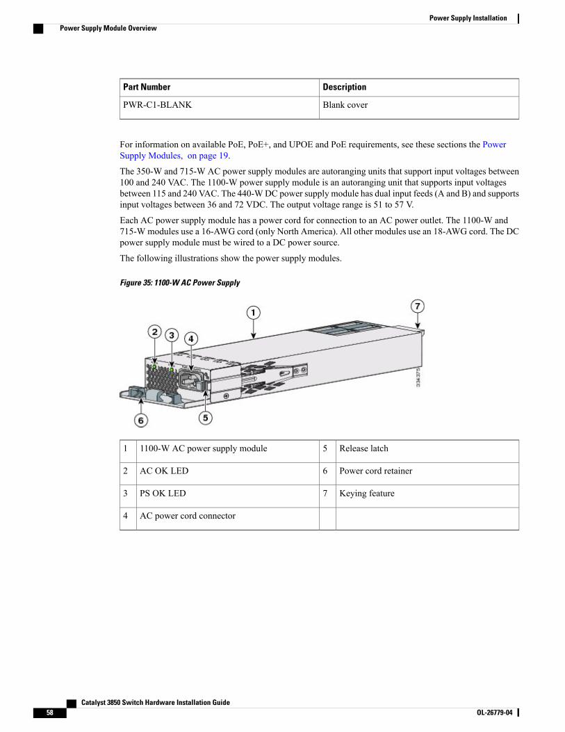
DescriptionPart Number
Blank coverPWR-C1-BLANK
For information on available PoE, PoE+, and UPOE and PoE requirements, see these sections the PowerSupply Modules, on page 19.
The 350-W and 715-W AC power supply modules are autoranging units that support input voltages between100 and 240 VAC. The 1100-W power supply module is an autoranging unit that supports input voltagesbetween 115 and 240 VAC. The 440-WDC power supply module has dual input feeds (A and B) and supportsinput voltages between 36 and 72 VDC. The output voltage range is 51 to 57 V.
Each AC power supply module has a power cord for connection to an AC power outlet. The 1100-W and715-W modules use a 16-AWG cord (only North America). All other modules use an 18-AWG cord. The DCpower supply module must be wired to a DC power source.
The following illustrations show the power supply modules.
Figure 35: 1100-W AC Power Supply
Release latch51100-W AC power supply module1
Power cord retainer6AC OK LED2
Keying feature7PS OK LED3
AC power cord connector4
Catalyst 3850 Switch Hardware Installation Guide58 OL-26779-04
Power Supply InstallationPower Supply Module Overview
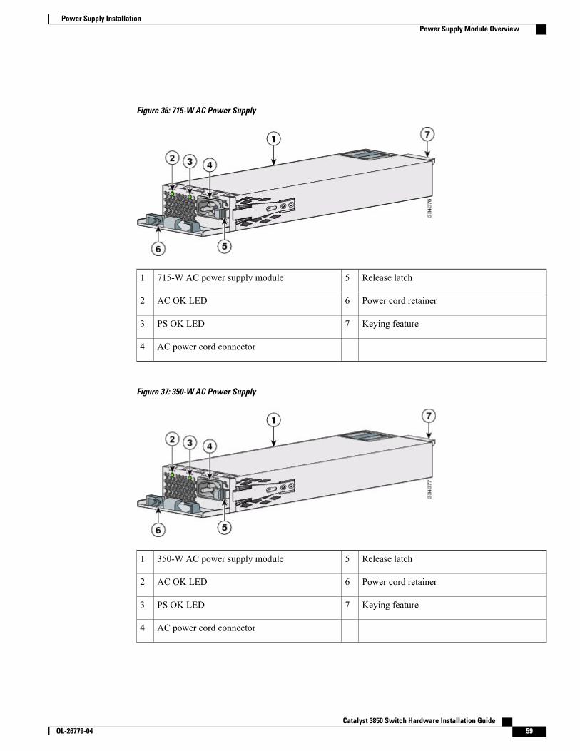
Figure 36: 715-W AC Power Supply
Release latch5715-W AC power supply module1
Power cord retainer6AC OK LED2
Keying feature7PS OK LED3
AC power cord connector4
Figure 37: 350-W AC Power Supply
Release latch5350-W AC power supply module1
Power cord retainer6AC OK LED2
Keying feature7PS OK LED3
AC power cord connector4
Catalyst 3850 Switch Hardware Installation Guide OL-26779-04 59
Power Supply InstallationPower Supply Module Overview
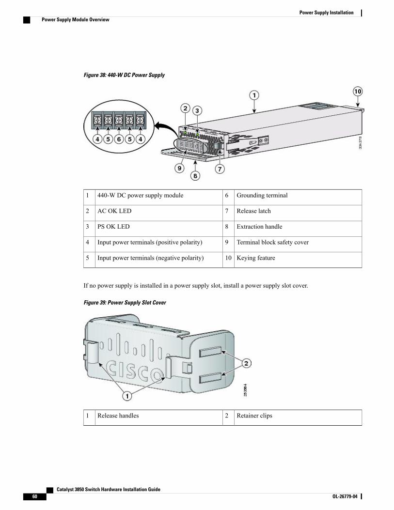
Figure 38: 440-W DC Power Supply
Grounding terminal6440-W DC power supply module1
Release latch7AC OK LED2
Extraction handle8PS OK LED3
Terminal block safety cover9Input power terminals (positive polarity)4
Keying feature10Input power terminals (negative polarity)5
If no power supply is installed in a power supply slot, install a power supply slot cover.
Figure 39: Power Supply Slot Cover
Retainer clips2Release handles1
Catalyst 3850 Switch Hardware Installation Guide60 OL-26779-04
Power Supply InstallationPower Supply Module Overview
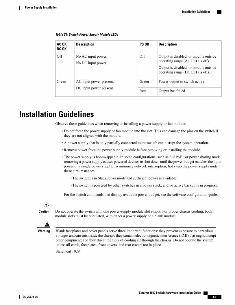
Table 24: Switch Power Supply Module LEDs
DescriptionPS OKDescriptionAC OKDC OK
Output is disabled, or input is outsideoperating range (AC LED is off).
Output is disabled, or input is outsideoperating range (DC LED is off).
OffNo AC input power.
No DC input power.
Off
Power output to switch active.GreenAC input power present.
DC input power present.
Green
Output has failed.Red
Installation GuidelinesObserve these guidelines when removing or installing a power supply or fan module:
• Do not force the power supply or fan module into the slot. This can damage the pins on the switch ifthey are not aligned with the module.
• A power supply that is only partially connected to the switch can disrupt the system operation.
• Remove power from the power-supply module before removing or installing the module.
• The power supply is hot-swappable. In some configurations, such as full PoE+ or power sharing mode,removing a power supply causes powered devices to shut down until the power budget matches the inputpower of a single power supply. To minimize network interruption, hot swap the power supply underthese circumstances:
◦The switch is in StackPower mode and sufficient power is available.
◦The switch is powered by other switches in a power stack, and no active backup is in progress.
For the switch commands that display available power budget, see the software configuration guide.
Do not operate the switch with one power-supply module slot empty. For proper chassis cooling, bothmodule slots must be populated, with either a power supply or a blank module.
Caution
Blank faceplates and cover panels serve three important functions: they prevent exposure to hazardousvoltages and currents inside the chassis; they contain electromagnetic interference (EMI) that might disruptother equipment; and they direct the flow of cooling air through the chassis. Do not operate the systemunless all cards, faceplates, front covers, and rear covers are in place.
Statement 1029
Warning
Catalyst 3850 Switch Hardware Installation Guide OL-26779-04 61
Power Supply InstallationInstallation Guidelines
Do not reach into a vacant slot or chassis while you install or remove a module. Exposed circuitry couldconstitute an energy hazard.
Statement 206
Warning
Only trained and qualified personnel should be allowed to install, replace, or service this equipment.
Statement 1030
Warning
If a Cisco external power system is not connected to the switch, install the provided connector cover onthe back of the switch.
Statement 386
Warning
Installing or Replacing an AC Power SupplyProcedure
Step 1 Turn off the power at its source.Step 2 Remove the power cord from the power cord retainer.Step 3 Remove the power cord from the power connector.Step 4 Press the release latch at the right side of the power supply module inward and slide the power supply out.
Do not leave the power-supply slot open for more than 90 seconds while the switch is operating.Caution
This unit might have more than one power supply connection. All connections must be removedto de-energize the unit. Statement 1028
Warning
Catalyst 3850 Switch Hardware Installation Guide62 OL-26779-04
Power Supply InstallationInstalling or Replacing an AC Power Supply
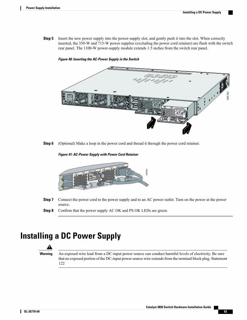
Step 5 Insert the new power supply into the power-supply slot, and gently push it into the slot. When correctlyinserted, the 350-W and 715-W power supplies (excluding the power cord retainer) are flush with the switchrear panel. The 1100-W power-supply module extends 1.5 inches from the switch rear panel.
Figure 40: Inserting the AC-Power Supply in the Switch
Step 6 (Optional) Make a loop in the power cord and thread it through the power cord retainer.
Figure 41: AC-Power Supply with Power Cord Retainer
Step 7 Connect the power cord to the power supply and to an AC power outlet. Turn on the power at the powersource.
Step 8 Confirm that the power supply AC OK and PS OK LEDs are green.
Installing a DC Power Supply
An exposed wire lead from a DC-input power source can conduct harmful levels of electricity. Be surethat no exposed portion of the DC-input power source wire extends from the terminal block plug. Statement122
Warning
Catalyst 3850 Switch Hardware Installation Guide OL-26779-04 63
Power Supply InstallationInstalling a DC Power Supply
Before performing any of the following procedures, ensure that power is removed from the DC circuit.Statement 1003
Warning
This product relies on the building's installation for short-circuit (overcurrent) protection. Ensure that theprotective device is rated not greater than: 20 A. Statement 1005
Warning
A readily accessible two-poled disconnect device must be incorporated in the fixed wiring. Statement1022
Warning
Hazardous voltage or energy may be present on power terminals. Always replace cover when terminalsare not in service. Be sure uninsulated conductors are not accessible when cover is in place. Statement1086
Warning
The grounding architecture of this product is DC-isolated (DC-I).Note
Equipment That You Need• Ratcheting torque screwdriver with a number-2 Phillips head that exerts up to 15 pound-force inches(lbf-in.) of pressure.
• Panduit crimping tool with optional controlled-cycle mechanism (model CT-720, CT-920, CT-920CH,CT-930, or CT-940CH).
•Wire-stripping tools.
• 12-gauge copper ground wire (insulated or not) for the single-hole ground connection.
• 8-gauge copper ground wire (insulated or not) for the dual-hole ground connection.
• Dual-hole ground lug and two screws (included in the DC power supply accessory kit) and single-holeground lug and screw (included in the switch accessory kit). The dual-hole lug is required for thegrounding of the switch in a NEBS installation where the DC supply is the only NEBS compliant powersupply option.
• Four leads of 14-gauge copper wire.
• Four fork-type terminals from the DC power supply accessory kit. The terminals must be the propersize for M3 screws in a Dinkle DT-35-B25-style terminal block.
Grounding the SwitchFollow these steps to install either a single-hole ground lug or a dual-hole ground lug on the switch. Makesure to follow any grounding requirements at your site.
Catalyst 3850 Switch Hardware Installation Guide64 OL-26779-04
Power Supply InstallationEquipment That You Need
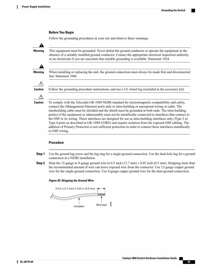
Before You Begin
Follow the grounding procedures at your site and observe these warnings:
This equipment must be grounded. Never defeat the ground conductor or operate the equipment in theabsence of a suitably installed ground conductor. Contact the appropriate electrical inspection authorityor an electrician if you are uncertain that suitable grounding is available. Statement 1024
Warning
When installing or replacing the unit, the ground connection must always be made first and disconnectedlast. Statement 1046
Warning
Follow the grounding procedure instructions, and use a UL-listed lug (included in the accessory kit).Caution
To comply with the Telcordia GR-1089 NEBS standard for electromagnetic compatibility and safety,connect the (Management Ethernet) ports only to intra-building or unexposed wiring or cable. Theintrabuilding cable must be shielded and the shield must be grounded at both ends. The intra-buildingport(s) of the equipment or subassembly must not be metallically connected to interfaces that connect tothe OSP or its wiring. These interfaces are designed for use as intra-building interfaces only (Type 2 orType 4 ports as described in GR-1089-CORE) and require isolation from the exposed OSP cabling. Theaddition of Primary Protectors is not sufficient protection in order to connect these interfaces metallicallyto OSP wiring.
Caution
Procedure
Step 1 Use the ground lug screw and the lug ring for a single-ground connection. Use the dual-hole lug for a groundconnection in a NEBS installation.
Step 2 Strip the 12-gauge or 8-gauge ground wire to 0.5 inch (12.7 mm) ± 0.02 inch (0.5 mm). Stripping more thanthe recommended amount of wire can leave exposed wire from the connector. Use 12-gauge copper groundwire for the single-ground connection. Use 8-gauge copper ground wire for the dual-ground connection.
Figure 42: Stripping the Ground Wire
Catalyst 3850 Switch Hardware Installation Guide OL-26779-04 65
Power Supply InstallationGrounding the Switch
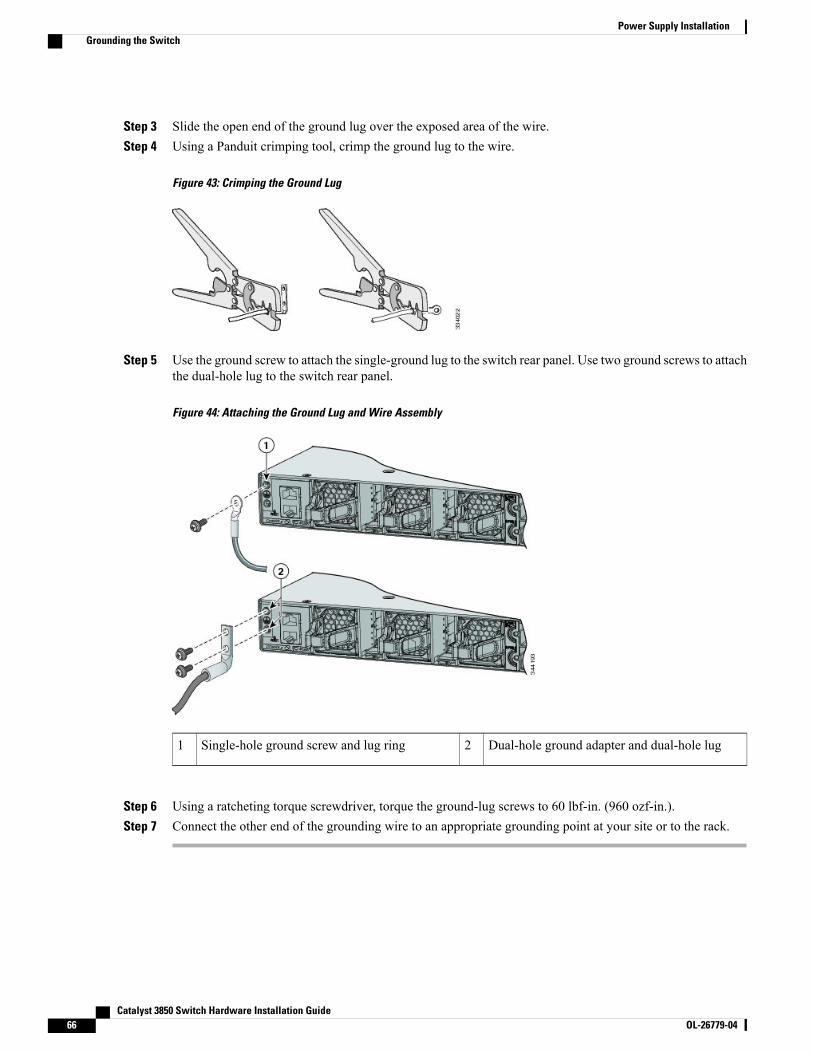
Step 3 Slide the open end of the ground lug over the exposed area of the wire.Step 4 Using a Panduit crimping tool, crimp the ground lug to the wire.
Figure 43: Crimping the Ground Lug
Step 5 Use the ground screw to attach the single-ground lug to the switch rear panel. Use two ground screws to attachthe dual-hole lug to the switch rear panel.
Figure 44: Attaching the Ground Lug and Wire Assembly
Dual-hole ground adapter and dual-hole lug2Single-hole ground screw and lug ring1
Step 6 Using a ratcheting torque screwdriver, torque the ground-lug screws to 60 lbf-in. (960 ozf-in.).Step 7 Connect the other end of the grounding wire to an appropriate grounding point at your site or to the rack.
Catalyst 3850 Switch Hardware Installation Guide66 OL-26779-04
Power Supply InstallationGrounding the Switch
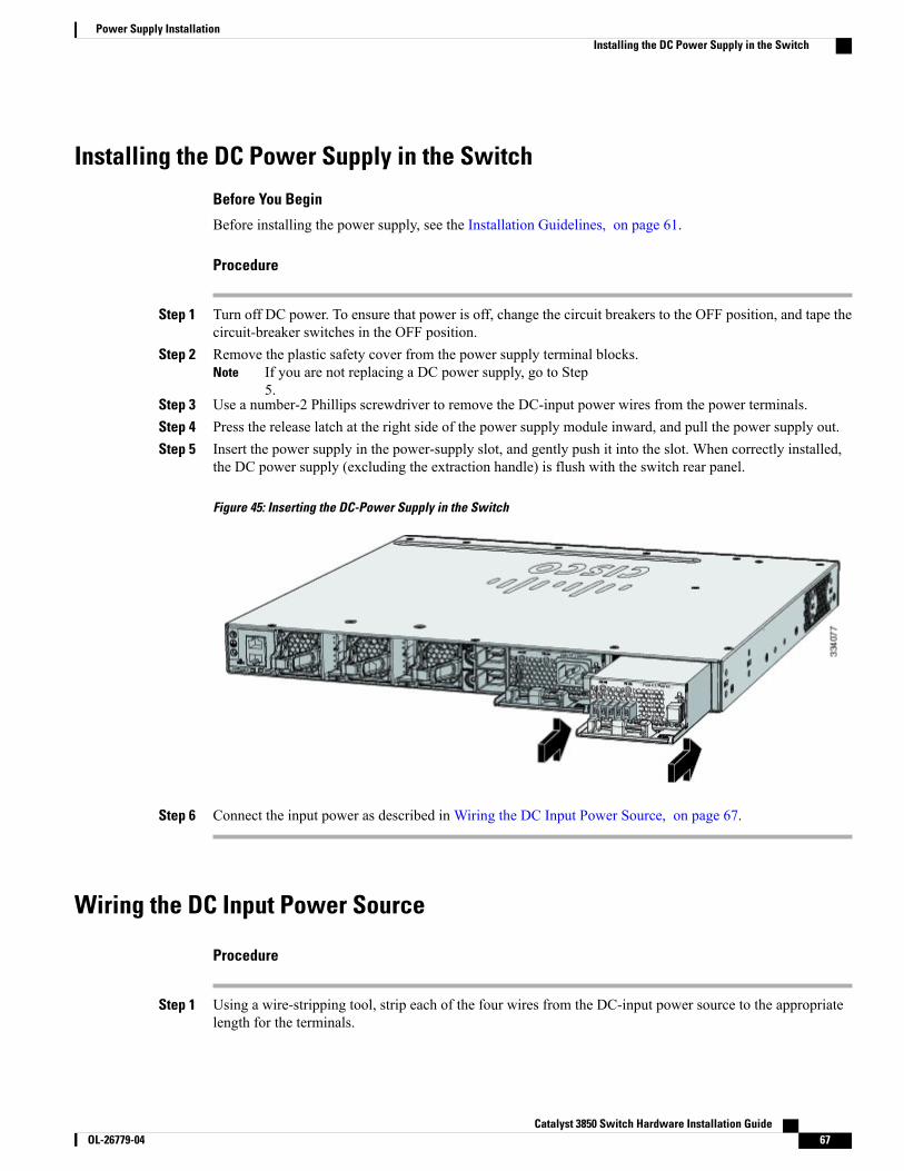
Installing the DC Power Supply in the Switch
Before You Begin
Before installing the power supply, see the Installation Guidelines, on page 61.
Procedure
Step 1 Turn off DC power. To ensure that power is off, change the circuit breakers to the OFF position, and tape thecircuit-breaker switches in the OFF position.
Step 2 Remove the plastic safety cover from the power supply terminal blocks.If you are not replacing a DC power supply, go to Step5.
Note
Step 3 Use a number-2 Phillips screwdriver to remove the DC-input power wires from the power terminals.Step 4 Press the release latch at the right side of the power supply module inward, and pull the power supply out.Step 5 Insert the power supply in the power-supply slot, and gently push it into the slot. When correctly installed,
the DC power supply (excluding the extraction handle) is flush with the switch rear panel.
Figure 45: Inserting the DC-Power Supply in the Switch
Step 6 Connect the input power as described in Wiring the DC Input Power Source, on page 67.
Wiring the DC Input Power Source
Procedure
Step 1 Using a wire-stripping tool, strip each of the four wires from the DC-input power source to the appropriatelength for the terminals.
Catalyst 3850 Switch Hardware Installation Guide OL-26779-04 67
Power Supply InstallationInstalling the DC Power Supply in the Switch
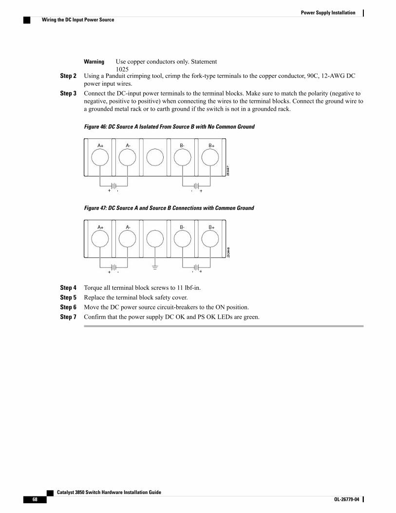
Use copper conductors only. Statement1025
Warning
Step 2 Using a Panduit crimping tool, crimp the fork-type terminals to the copper conductor, 90C, 12-AWG DCpower input wires.
Step 3 Connect the DC-input power terminals to the terminal blocks. Make sure to match the polarity (negative tonegative, positive to positive) when connecting the wires to the terminal blocks. Connect the ground wire toa grounded metal rack or to earth ground if the switch is not in a grounded rack.
Figure 46: DC Source A Isolated From Source B with No Common Ground
Figure 47: DC Source A and Source B Connections with Common Ground
Step 4 Torque all terminal block screws to 11 lbf-in.Step 5 Replace the terminal block safety cover.Step 6 Move the DC power source circuit-breakers to the ON position.Step 7 Confirm that the power supply DC OK and PS OK LEDs are green.
Catalyst 3850 Switch Hardware Installation Guide68 OL-26779-04
Power Supply InstallationWiring the DC Input Power Source
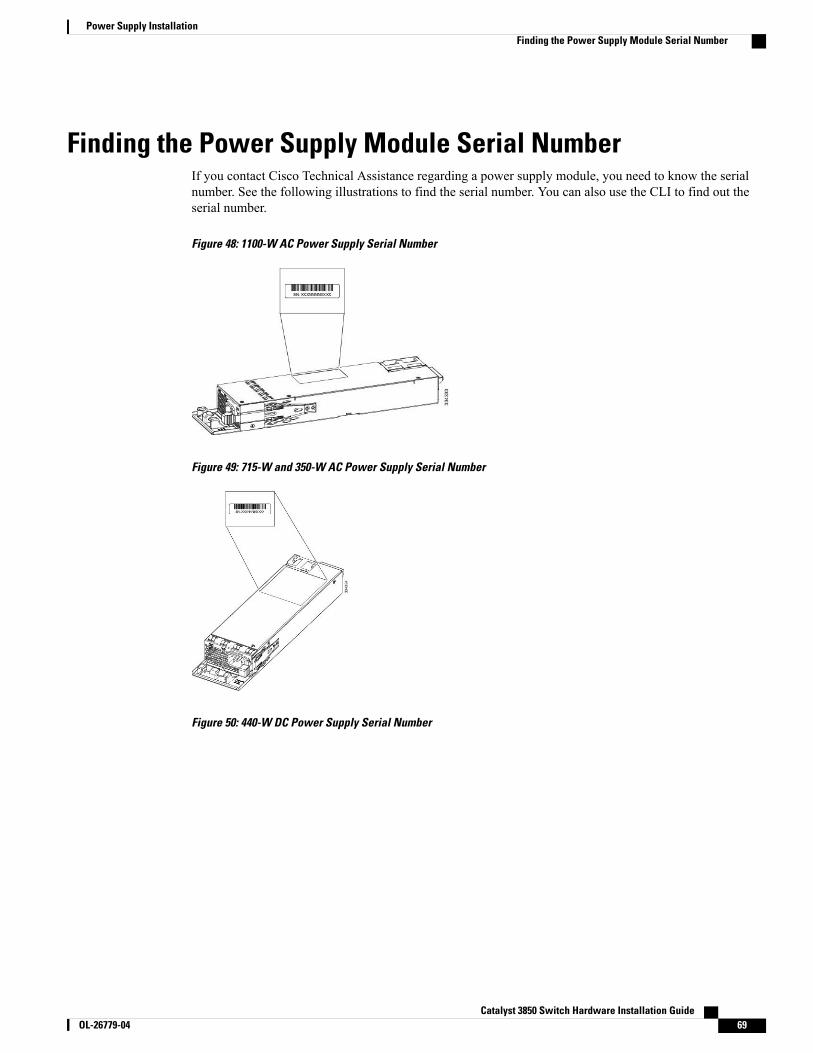
Finding the Power Supply Module Serial NumberIf you contact Cisco Technical Assistance regarding a power supply module, you need to know the serialnumber. See the following illustrations to find the serial number. You can also use the CLI to find out theserial number.
Figure 48: 1100-W AC Power Supply Serial Number
Figure 49: 715-W and 350-W AC Power Supply Serial Number
Figure 50: 440-W DC Power Supply Serial Number
Catalyst 3850 Switch Hardware Installation Guide OL-26779-04 69
Power Supply InstallationFinding the Power Supply Module Serial Number
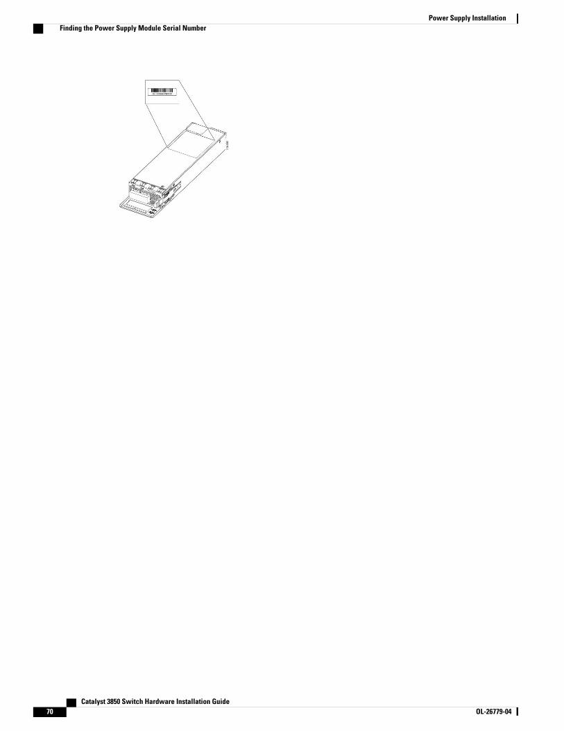
Catalyst 3850 Switch Hardware Installation Guide70 OL-26779-04
Power Supply InstallationFinding the Power Supply Module Serial Number
C H A P T E R 5Installing the Fan
• Fan Module Overview , page 71
• Installation Guidelines, page 72
• Installing a Fan Module, page 73
• Finding the Fan Module Serial Number, page 74
Fan Module OverviewThe switch has three fan modules. Fan modules are hot-swappable. A powered switch should always havemore than one operational fan. The switch can operate with two operational fans and one nonfunctional fan,but the failed fan should be replaced as soon as possible to avoid a service interruption due to a second fanfault.
Catalyst 3850 Switch Hardware Installation Guide OL-26779-04 71
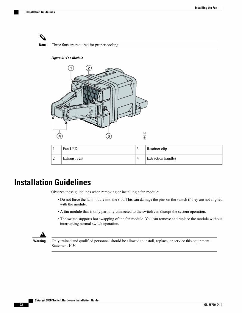
Three fans are required for proper cooling.Note
Figure 51: Fan Module
Retainer clip3Fan LED1
Extraction handles4Exhaust vent2
Installation GuidelinesObserve these guidelines when removing or installing a fan module:
• Do not force the fan module into the slot. This can damage the pins on the switch if they are not alignedwith the module.
• A fan module that is only partially connected to the switch can disrupt the system operation.
• The switch supports hot swapping of the fan module. You can remove and replace the module withoutinterrupting normal switch operation.
Only trained and qualified personnel should be allowed to install, replace, or service this equipment.Statement 1030
Warning
Catalyst 3850 Switch Hardware Installation Guide72 OL-26779-04
Installing the FanInstallation Guidelines
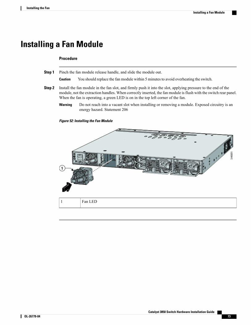
Installing a Fan ModuleProcedure
Step 1 Pinch the fan module release handle, and slide the module out.
You should replace the fan module within 5 minutes to avoid overheating the switch.Caution
Step 2 Install the fan module in the fan slot, and firmly push it into the slot, applying pressure to the end of themodule, not the extraction handles. When correctly inserted, the fan module is flush with the switch rear panel.When the fan is operating, a green LED is on in the top left corner of the fan.
Do not reach into a vacant slot when installing or removing a module. Exposed circuitry is anenergy hazard. Statement 206
Warning
Figure 52: Installing the Fan Module
Fan LED1
Catalyst 3850 Switch Hardware Installation Guide OL-26779-04 73
Installing the FanInstalling a Fan Module
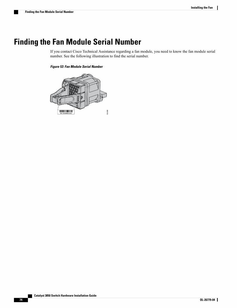
Finding the Fan Module Serial NumberIf you contact Cisco Technical Assistance regarding a fan module, you need to know the fan module serialnumber. See the following illustration to find the serial number.
Figure 53: Fan Module Serial Number
Catalyst 3850 Switch Hardware Installation Guide74 OL-26779-04
Installing the FanFinding the Fan Module Serial Number
C H A P T E R 6Troubleshooting
• Diagnosing Problems, page 75
• Replacing a Failed Data Stack Member, page 79
Diagnosing ProblemsThe LEDs on the front panel provide troubleshooting information about the switch. They show POST failures,port-connectivity problems, and overall switch performance. You can also get statistics fromDeviceManager,from the CLI, or from an SNMP workstation.
Switch POST Results
POST failures are usually fatal. Contact your Cisco technical support representative if your switch doesnot pass POST.
Note
Switch LEDsIf you have physical access to the switch, look at the port LEDs for troubleshooting information about theswitch. See the LED section for a description of the LED colors and their meanings.
Switch Connections
Bad or Damaged CableAlways examine the cable for marginal damage or failure. A cable might be just good enough to connect atthe physical layer, but it could corrupt packets as a result of subtle damage to the wiring or connectors. You
Catalyst 3850 Switch Hardware Installation Guide OL-26779-04 75
can identify this situation because the port has many packet errors or the port constantly flaps (loses andregains link).
• Examine or exchange the copper or fiber-optic cable with a known, good cable.
• Look for broken or missing pins on cable connectors.
• Rule out any bad patch panel connections or media convertors between the source and the destination.If possible, bypass the patch panel, or eliminate faulty media convertors (fiber-optic-to-copper).
• Try the cable in another port or interface, if possible, to see if the problem follows the cable.
• Remove and inspect the stack cable and stack port for bent pins or damaged connectors. If the cable isbad, replace it with a known good cable.
Ethernet and Fiber-Optic CablesMake sure that you have the correct cable for the connection.
• For Ethernet, use Category 3 copper cable for 10Mb/s UTP connections. Use either Category 5, Category5e, or Category 6 UTP for 10/100/1000 Mb/s connections.
• For fiber-optic cables, verify that you have the correct cable for the distance and port type. Make surethat the connected device ports both match and use the same type encoding, optical frequency, and fibertype.
• For copper connections, determine if a crossover cable was used when a straight-through was requiredor the reverse. Enable auto-MDIX on the switch, or replace the cable.
Link StatusVerify that both sides have link. A single broken wire or a shutdown port can cause one side to show linkeven though the other side does not have link.
A port LED that is on does not guarantee that the cable is fully functional. The cable might have encounteredphysical stress that causes it to function at a marginal level. If the port LED does not turn on:
• Connect the cable from the switch to a known good device.
• Make sure that both ends of the cable are connected to the correct ports.
• Verify that both devices have power.
• Verify that you are using the correct cable type.
• Look for loose connections. Sometimes a cable appears to be seated, but is not. Disconnect the cableand then reconnect it.
10/100/1000 Port ConnectionsA port appears to malfunction:
• Use the Mode button to show the status for all ports.
• Use the show interfaces privileged EXEC command to see if the port is error-disabled, disabled, orshutdown. Reenable the port if necessary.
Catalyst 3850 Switch Hardware Installation Guide76 OL-26779-04
TroubleshootingSwitch Connections
10/100/1000 PoE+ Port ConnectionsA powered device connected to a PoE port does not receive power:
• Use the Mode button to show the PoE status for all ports.
• Use the show interfaces privileged EXEC command to see if the port is in error-disabled, disabled, orshutdown. Reenable the port if necessary.
• Verify that the power supply installed in the switch meets the power requirements of your connecteddevices.
• Verify that there is sufficient PoE power budget to provide power to the attached device. Use the showpower inline global configuration command to check on the available PoE power budget.
• Verify the cable type. Many legacy powered devices, including older Cisco IP phones and access pointsthat do not fully support IEEE 802.3af, might not support PoE when connected to the switch by acrossover cable. Replace the crossover cable with a straight-through cable.
Noncompliant cabling or powered devices can cause a PoE port fault. Use onlystandard-compliant cabling to connect Cisco prestandard IP Phones and wireless accesspoints or IEEE 802.3af-compliant devices. You must remove any cable or device thatcauses a PoE fault.
Caution
SFP and SFP+ ModuleUse only Cisco SFP or SFP+ modules in the switch. Each Cisco module has an internal serial EEPROM thatis encoded with security information. This encoding provides a way for Cisco to identify and validate that themodule meets the requirements for the switch.
• Inspect the SFP module. Exchange the suspect module with a known good module. Verify that themodule is supported on this platform. (The switch release notes on Cisco.com list the SFP modules thatthe switch supports.)
• Use the show interfaces privileged EXEC command to see if the port or module is error-disabled,disabled, or shutdown. Reenable the port if needed.
• Make sure that all fiber-optic connections are properly cleaned and securely connected.
Interface SettingsVerify that the interface is not disabled or powered off. If an interface is manually shut down on either sideof the link, it does not come up until you reenable the interface. Use the show interfaces privileged EXECcommand to see if the interface is error-disabled, disabled, or shutdown on either side of the connection. Ifneeded, reenable the interface.
Catalyst 3850 Switch Hardware Installation Guide OL-26779-04 77
TroubleshootingSwitch Connections
Ping End DevicePing from the directly connected switch first, and then work your way back port by port, interface by interface,trunk by trunk, until you find the source of the connectivity issue. Make sure that each switch can identifythe end device MAC address in its Content-Addressable Memory (CAM) table.
Spanning Tree LoopsSTP loops can cause serious performance issues that look like port or interface problems.
A unidirectional link can cause loops. It occurs when the traffic sent by the switch is received by its neighbor,but the traffic from the neighbor is not received by the switch. A broken fiber-optic cable, other cablingproblems, or a port issue could cause this one-way communication.
You can enable UniDirectional Link Detection (UDLD) on the switch to help identify unidirectional linkproblems.
Switch Performance
Speed, Duplex, and AutonegotiationIf the port statistics show a large amount of alignment errors, frame check sequence (FCS), or late-collisionserrors, this might mean a speed or duplex mismatch.
A common issue with speed and duplex occurs when duplex and speed settings are mismatched between twoswitches, between a switch and a router, or between the switch and a workstation or server. Mismatches canhappen when manually setting the speed and duplex or from autonegotiation issues between the two devices.
To maximize switch performance and to ensure a link, follow one of these guidelines when changing theduplex or the speed settings.
• Let both ports autonegotiate both speed and duplex.
• Manually set the speed and duplex parameters for the interfaces on both ends of the connection.
• If a remote device does not autonegotiate, use the same duplex settings on the two ports. The speedparameter adjusts itself even if the connected port does not autonegotiate.
Autonegotiation and Network Interface CardsProblems sometimes occur between the switch and third-party network interface cards (NICs). By default,the switch ports and interfaces autonegotiate. Laptops or other devices are commonly set to autonegotiate,yet sometimes autonegotiation issues occur.
To troubleshoot autonegotiation problems, try manually setting both sides of the connection. If this does notsolve the problem, there could be a problem with the firmware or software on your NIC. You can resolve thisby upgrading the NIC driver to the latest version.
Catalyst 3850 Switch Hardware Installation Guide78 OL-26779-04
TroubleshootingSwitch Performance
Cabling DistanceIf the port statistics show excessive FCS, late-collision, or alignment errors, verify that the cable distancefrom the switch to the connected device meets the recommended guidelines.
Clearing the Switch IP Address and ConfigurationIf you have configured a new switch with a wrong IP address, or if all of the switch LEDs start blinking whenyou are trying to enter Express Setup mode, you can clear the configured IP address. The switch returns tothe factory default settings.
This procedure clears the IP address and all configuration information stored on the switch. Do not followthis procedure unless you want to completely reconfigure the switch.
Note
Procedure
Step 1 If you are using Cisco IOS XE Release 3E or later releases, enter the erase startup-config privileged EXECcommand to clear the contents of your startup configuration.
Step 2 Press and hold theMode button. The switch LEDs blink after about 2 seconds. If the switch is not configured,the LEDs above the Mode button turn green. You can omit the next step.
Step 3 Continue holding down theMode button. The LEDs stop blinking after 8 seconds, and then the switch reboots.You can now configure the switch by using Express Setup as described in the switch getting started guide.
You can also configure the switch by using the CLI setup procedure described in the appendix.
Replacing a Failed Data Stack MemberProcedure
Step 1 The replacement switch must be a Catalyst 3850 switch.Step 2 Power down the failed switch. Remove AC or DC input power, and if the switch is part of a StackPower stack,
remove the StackPower cables.Step 3 Make sure the replacement switch is powered off, and then connect it to the stack. If you had manually set
the member numbers for the switch stack, manually assign the member number of the failed switch to thereplacement switch. To manually assign the stack member number, see the switch software configurationguide on Cisco.com.
Step 4 Make the same Gigabit Ethernet connections on the replacement switch that were on the failed switch.Step 5 Reinstall any modules, and make cable connections.Step 6 Power on the replacement switch.
Catalyst 3850 Switch Hardware Installation Guide OL-26779-04 79
TroubleshootingClearing the Switch IP Address and Configuration

The replacement switch has the same configuration for all the interfaces as the failed switch and functionsthe same as the failed switch.
Catalyst 3850 Switch Hardware Installation Guide80 OL-26779-04
TroubleshootingReplacing a Failed Data Stack Member

A P P E N D I X ATechnical Specifications
• Environmental and Physical Specifications, page 81
• Specifications for the Power Supplies, Switches, and Fan, page 83
Environmental and Physical SpecificationsThis table describes the environmental specifications.
Table 25: Environmental Specifications for the Switch
Environmental Ranges
23 to 113°F (–5 to 45°C)Operating temperature15
–40 to 158°F (–40 to 70°C)Storage temperature
5 to 95% (noncondensing)Relative humidity
Up to 10,000 ft (3000 m)Operating altitude
Up to 15,000 ft (4500 m)Storage altitude
15 Minimum ambient temperature for cold start is 32°F (0°C)
This table describes the environmental specifications.
Table 26: Environmental Specifications for the Power Supplies
Environmental Ranges
AC power supply: 23 to 113°F (–5 to 45°C)DC power supply: 23 to 131°F (–5 to 55°C)
Operating temperature
Catalyst 3850 Switch Hardware Installation Guide OL-26779-04 81
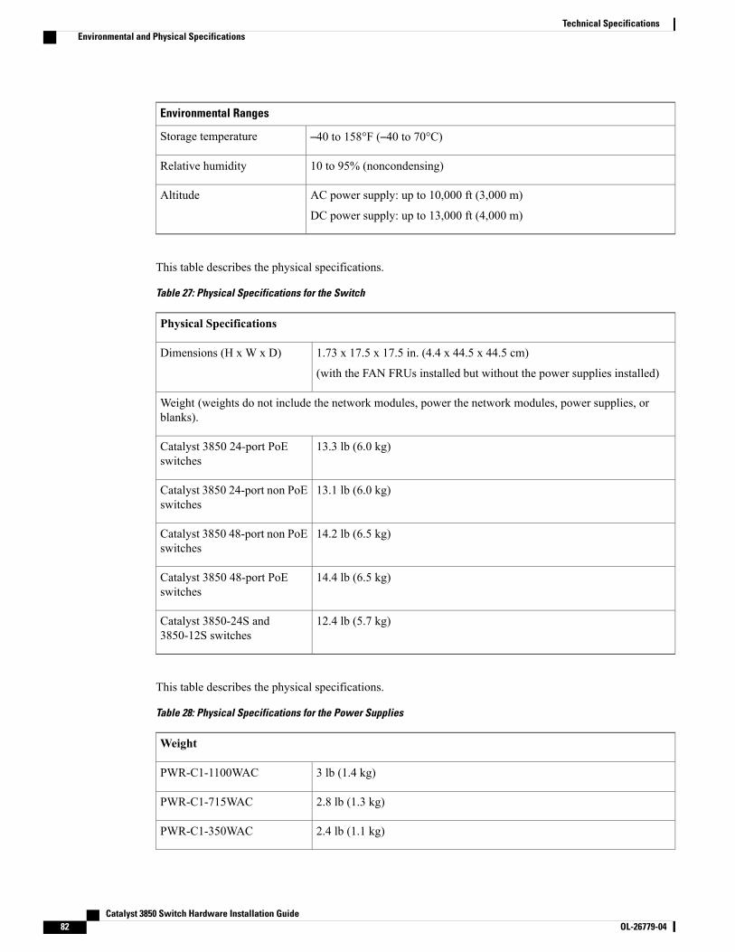
Environmental Ranges
–40 to 158°F (–40 to 70°C)Storage temperature
10 to 95% (noncondensing)Relative humidity
AC power supply: up to 10,000 ft (3,000 m)
DC power supply: up to 13,000 ft (4,000 m)
Altitude
This table describes the physical specifications.
Table 27: Physical Specifications for the Switch
Physical Specifications
1.73 x 17.5 x 17.5 in. (4.4 x 44.5 x 44.5 cm)
(with the FAN FRUs installed but without the power supplies installed)
Dimensions (H x W x D)
Weight (weights do not include the network modules, power the network modules, power supplies, orblanks).
13.3 lb (6.0 kg)Catalyst 3850 24-port PoEswitches
13.1 lb (6.0 kg)Catalyst 3850 24-port non PoEswitches
14.2 lb (6.5 kg)Catalyst 3850 48-port non PoEswitches
14.4 lb (6.5 kg)Catalyst 3850 48-port PoEswitches
12.4 lb (5.7 kg)Catalyst 3850-24S and3850-12S switches
This table describes the physical specifications.
Table 28: Physical Specifications for the Power Supplies
Weight
3 lb (1.4 kg)PWR-C1-1100WAC
2.8 lb (1.3 kg)PWR-C1-715WAC
2.4 lb (1.1 kg)PWR-C1-350WAC
Catalyst 3850 Switch Hardware Installation Guide82 OL-26779-04
Technical SpecificationsEnvironmental and Physical Specifications
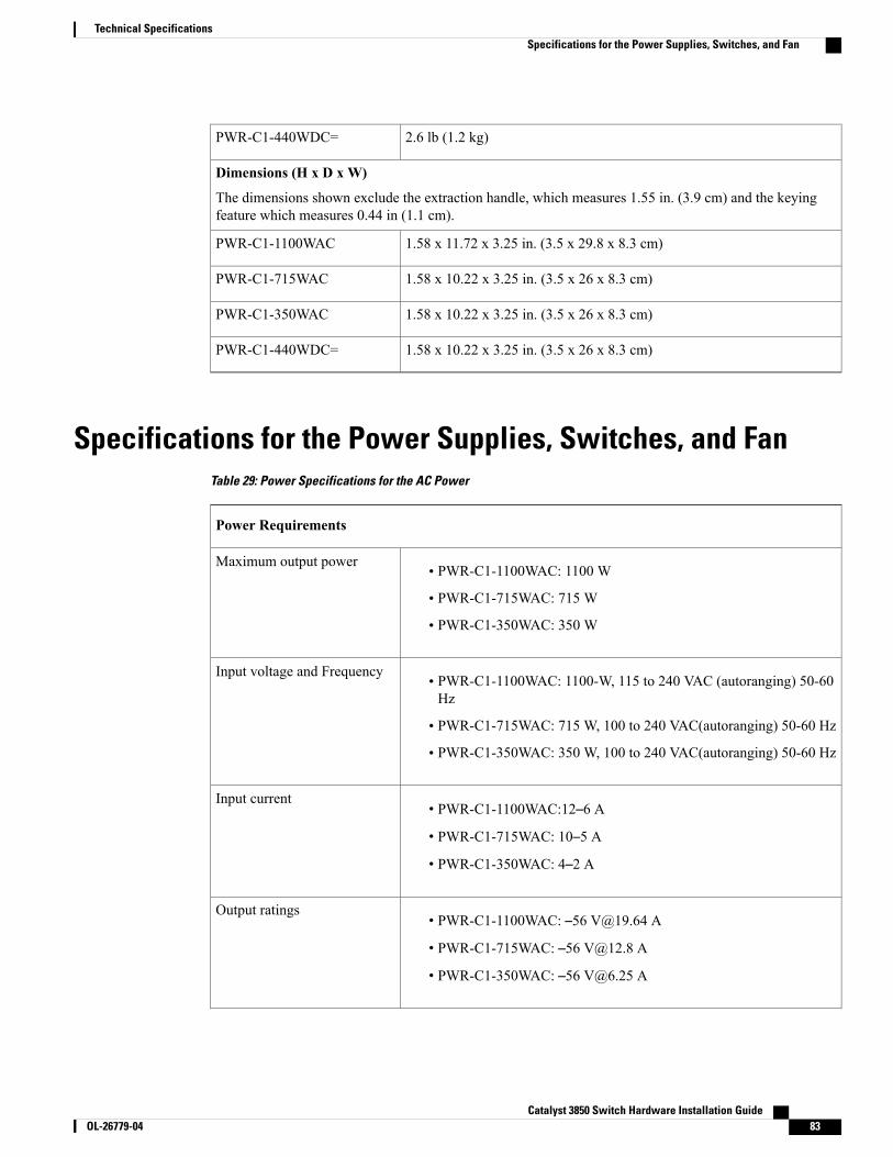
2.6 lb (1.2 kg)PWR-C1-440WDC=
Dimensions (H x D x W)
The dimensions shown exclude the extraction handle, which measures 1.55 in. (3.9 cm) and the keyingfeature which measures 0.44 in (1.1 cm).
1.58 x 11.72 x 3.25 in. (3.5 x 29.8 x 8.3 cm)PWR-C1-1100WAC
1.58 x 10.22 x 3.25 in. (3.5 x 26 x 8.3 cm)PWR-C1-715WAC
1.58 x 10.22 x 3.25 in. (3.5 x 26 x 8.3 cm)PWR-C1-350WAC
1.58 x 10.22 x 3.25 in. (3.5 x 26 x 8.3 cm)PWR-C1-440WDC=
Specifications for the Power Supplies, Switches, and FanTable 29: Power Specifications for the AC Power
Power Requirements
• PWR-C1-1100WAC: 1100 W
• PWR-C1-715WAC: 715 W
• PWR-C1-350WAC: 350 W
Maximum output power
• PWR-C1-1100WAC: 1100-W, 115 to 240 VAC (autoranging) 50-60Hz
• PWR-C1-715WAC: 715 W, 100 to 240 VAC(autoranging) 50-60 Hz
• PWR-C1-350WAC: 350 W, 100 to 240 VAC(autoranging) 50-60 Hz
Input voltage and Frequency
• PWR-C1-1100WAC:12–6 A
• PWR-C1-715WAC: 10–5 A
• PWR-C1-350WAC: 4–2 A
Input current
• PWR-C1-1100WAC: –56 [email protected] A
• PWR-C1-715WAC: –56 [email protected] A
• PWR-C1-350WAC: –56 [email protected] A
Output ratings
Catalyst 3850 Switch Hardware Installation Guide OL-26779-04 83
Technical SpecificationsSpecifications for the Power Supplies, Switches, and Fan
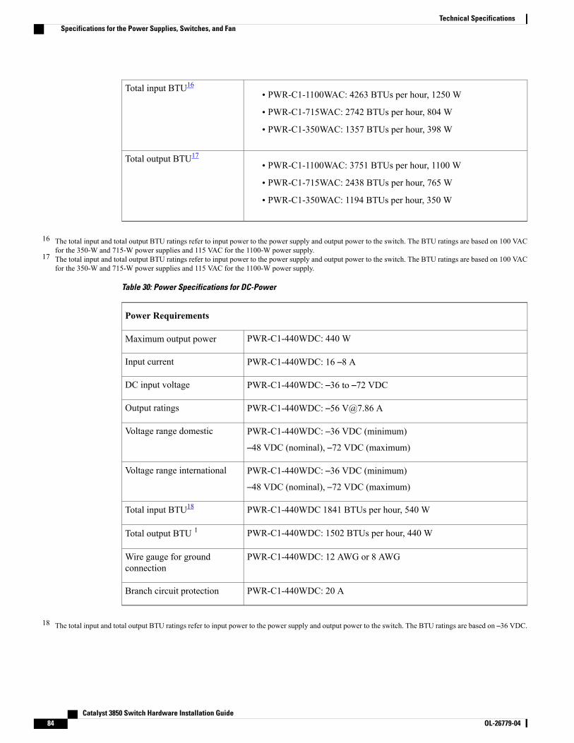
• PWR-C1-1100WAC: 4263 BTUs per hour, 1250 W
• PWR-C1-715WAC: 2742 BTUs per hour, 804 W
• PWR-C1-350WAC: 1357 BTUs per hour, 398 W
Total input BTU16
• PWR-C1-1100WAC: 3751 BTUs per hour, 1100 W
• PWR-C1-715WAC: 2438 BTUs per hour, 765 W
• PWR-C1-350WAC: 1194 BTUs per hour, 350 W
Total output BTU17
16 The total input and total output BTU ratings refer to input power to the power supply and output power to the switch. The BTU ratings are based on 100 VACfor the 350-W and 715-W power supplies and 115 VAC for the 1100-W power supply.
17 The total input and total output BTU ratings refer to input power to the power supply and output power to the switch. The BTU ratings are based on 100 VACfor the 350-W and 715-W power supplies and 115 VAC for the 1100-W power supply.
Table 30: Power Specifications for DC-Power
Power Requirements
PWR-C1-440WDC: 440 WMaximum output power
PWR-C1-440WDC: 16 –8 AInput current
PWR-C1-440WDC: –36 to –72 VDCDC input voltage
PWR-C1-440WDC: –56 [email protected] AOutput ratings
PWR-C1-440WDC: –36 VDC (minimum)
–48 VDC (nominal), –72 VDC (maximum)
Voltage range domestic
PWR-C1-440WDC: –36 VDC (minimum)
–48 VDC (nominal), –72 VDC (maximum)
Voltage range international
PWR-C1-440WDC 1841 BTUs per hour, 540 WTotal input BTU18
PWR-C1-440WDC: 1502 BTUs per hour, 440 WTotal output BTU 1
PWR-C1-440WDC: 12 AWG or 8 AWGWire gauge for groundconnection
PWR-C1-440WDC: 20 ABranch circuit protection
18 The total input and total output BTU ratings refer to input power to the power supply and output power to the switch. The BTU ratings are based on –36 VDC.
Catalyst 3850 Switch Hardware Installation Guide84 OL-26779-04
Technical SpecificationsSpecifications for the Power Supplies, Switches, and Fan
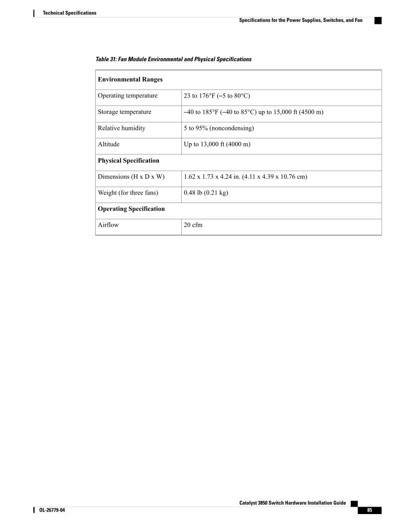
Table 31: Fan Module Environmental and Physical Specifications
Environmental Ranges
23 to 176°F (–5 to 80°C)Operating temperature
–40 to 185°F (–40 to 85°C) up to 15,000 ft (4500 m)Storage temperature
5 to 95% (noncondensing)Relative humidity
Up to 13,000 ft (4000 m)Altitude
Physical Specification
1.62 x 1.73 x 4.24 in. (4.11 x 4.39 x 10.76 cm)Dimensions (H x D x W)
0.48 lb (0.21 kg)Weight (for three fans)
Operating Specification
20 cfmAirflow
Catalyst 3850 Switch Hardware Installation Guide OL-26779-04 85
Technical SpecificationsSpecifications for the Power Supplies, Switches, and Fan

Catalyst 3850 Switch Hardware Installation Guide86 OL-26779-04
Technical SpecificationsSpecifications for the Power Supplies, Switches, and Fan
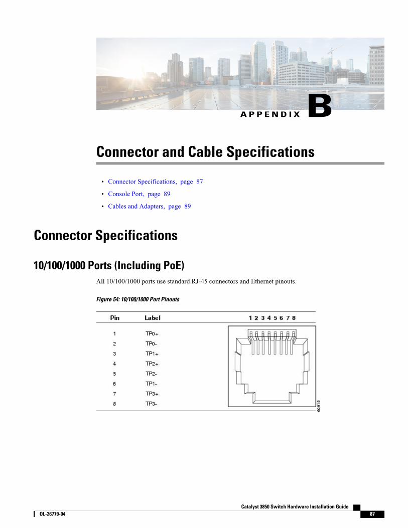
A P P E N D I X BConnector and Cable Specifications
• Connector Specifications, page 87
• Console Port, page 89
• Cables and Adapters, page 89
Connector Specifications
10/100/1000 Ports (Including PoE)All 10/100/1000 ports use standard RJ-45 connectors and Ethernet pinouts.
Figure 54: 10/100/1000 Port Pinouts
Catalyst 3850 Switch Hardware Installation Guide OL-26779-04 87
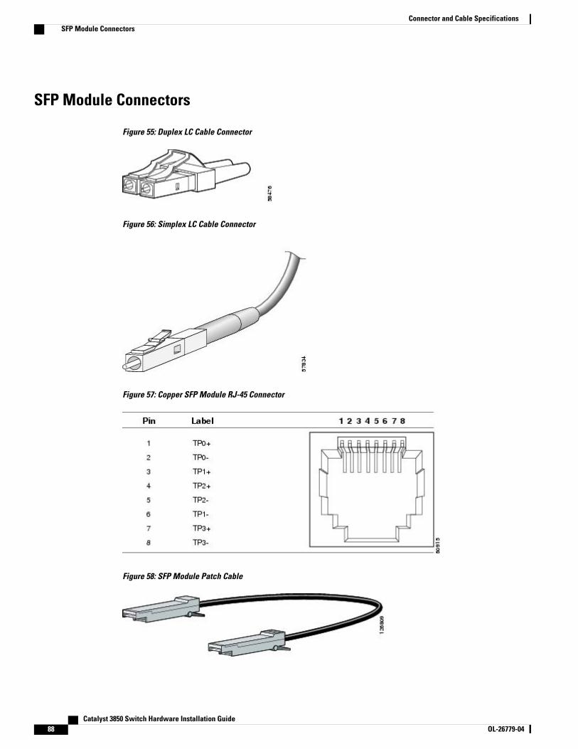
SFP Module Connectors
Figure 55: Duplex LC Cable Connector
Figure 56: Simplex LC Cable Connector
Figure 57: Copper SFP Module RJ-45 Connector
Figure 58: SFP Module Patch Cable
Catalyst 3850 Switch Hardware Installation Guide88 OL-26779-04
Connector and Cable SpecificationsSFP Module Connectors
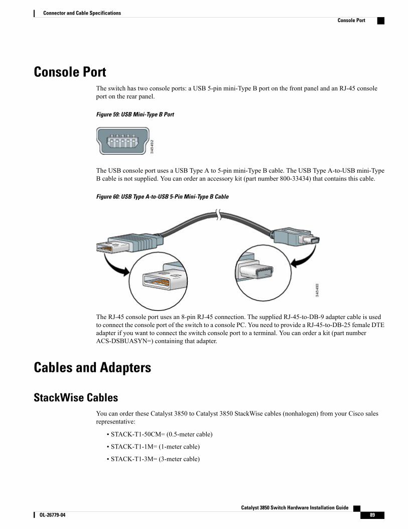
Console PortThe switch has two console ports: a USB 5-pin mini-Type B port on the front panel and an RJ-45 consoleport on the rear panel.
Figure 59: USB Mini-Type B Port
The USB console port uses a USB Type A to 5-pin mini-Type B cable. The USB Type A-to-USB mini-TypeB cable is not supplied. You can order an accessory kit (part number 800-33434) that contains this cable.
Figure 60: USB Type A-to-USB 5-Pin Mini-Type B Cable
The RJ-45 console port uses an 8-pin RJ-45 connection. The supplied RJ-45-to-DB-9 adapter cable is usedto connect the console port of the switch to a console PC. You need to provide a RJ-45-to-DB-25 female DTEadapter if you want to connect the switch console port to a terminal. You can order a kit (part numberACS-DSBUASYN=) containing that adapter.
Cables and Adapters
StackWise CablesYou can order these Catalyst 3850 to Catalyst 3850 StackWise cables (nonhalogen) from your Cisco salesrepresentative:
• STACK-T1-50CM= (0.5-meter cable)
• STACK-T1-1M= (1-meter cable)
• STACK-T1-3M= (3-meter cable)
Catalyst 3850 Switch Hardware Installation Guide OL-26779-04 89
Connector and Cable SpecificationsConsole Port

SFP Module CablesFor cabling specifications, refer to the Cisco SFP and SFP+ Transceiver Module Installation Notes.
Each port must match the wave-length specifications on the other end of the cable, and the cable must notexceed the stipulated cable length. Copper 1000BASE-T SFPmodule transceivers use standard four twisted-pair,Category 5 cable at lengths up to 328 feet (100 meters).
Catalyst 3850 Switch Hardware Installation Guide90 OL-26779-04
Connector and Cable SpecificationsSFP Module Cables
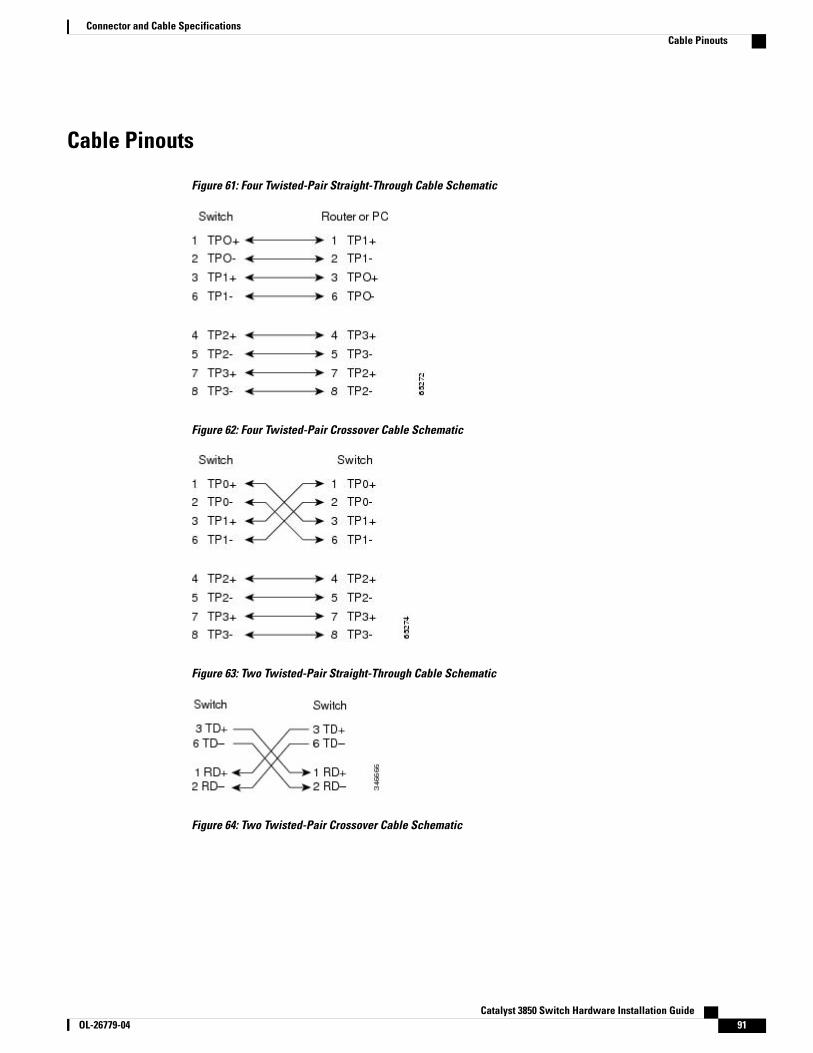
Cable Pinouts
Figure 61: Four Twisted-Pair Straight-Through Cable Schematic
Figure 62: Four Twisted-Pair Crossover Cable Schematic
Figure 63: Two Twisted-Pair Straight-Through Cable Schematic
Figure 64: Two Twisted-Pair Crossover Cable Schematic
Catalyst 3850 Switch Hardware Installation Guide OL-26779-04 91
Connector and Cable SpecificationsCable Pinouts
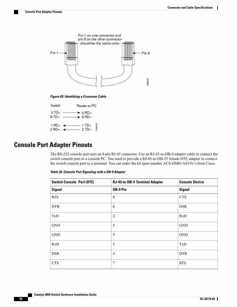
Figure 65: Identifying a Crossover Cable
Console Port Adapter PinoutsThe RS-232 console port uses an 8-pin RJ-45 connector. Use an RJ-45-to-DB-9 adapter cable to connect theswitch console port to a console PC. You need to provide a RJ-45-to-DB-25 female DTE adapter to connectthe switch console port to a terminal. You can order the kit (part number ACS-DSBUASYN=) from Cisco.
Table 32: Console Port Signaling with a DB-9 Adapter
Console DeviceRJ-45-to-DB-9 Terminal AdapterSwitch Console Port (DTE)
SignalDB-9 PinSignal
CTS8RTS
DSR6DTR
RxD2TxD
GND5GND
GND5GND
TxD3RxD
DTR4DSR
RTS7CTS
Catalyst 3850 Switch Hardware Installation Guide92 OL-26779-04
Connector and Cable SpecificationsConsole Port Adapter Pinouts
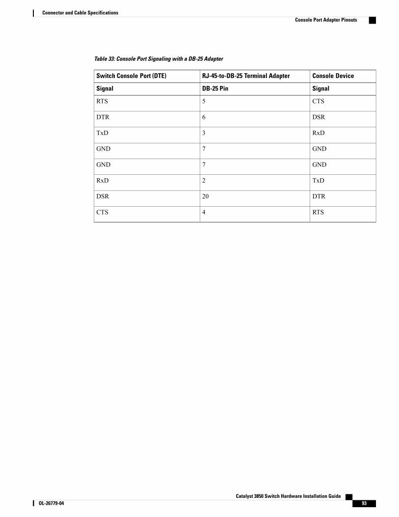
Table 33: Console Port Signaling with a DB-25 Adapter
Console DeviceRJ-45-to-DB-25 Terminal AdapterSwitch Console Port (DTE)
SignalDB-25 PinSignal
CTS5RTS
DSR6DTR
RxD3TxD
GND7GND
GND7GND
TxD2RxD
DTR20DSR
RTS4CTS
Catalyst 3850 Switch Hardware Installation Guide OL-26779-04 93
Connector and Cable SpecificationsConsole Port Adapter Pinouts

Catalyst 3850 Switch Hardware Installation Guide94 OL-26779-04
Connector and Cable SpecificationsConsole Port Adapter Pinouts
A P P E N D I X CConfiguring the Switch with the CLI-Based SetupProgram
• Accessing the CLI Through Express Setup, page 95
• Accessing the CLI Through the Console Port, page 95
• Entering the Initial Configuration Information, page 101
Accessing the CLI Through Express SetupYou can access the CLI on an unconfigured switch. Set the switch in Express Setup mode and connect aswitch Ethernet port to an Ethernet port on your PC or workstation. Follow the steps described in the gettingstarted guide for turning on the switch and using Express Setup.
When the switch is in Express Setup mode, open a Telnet session to the switch by entering the IP address10.0.0.1. Enter the setup user EXEC command. Enter the information described in IP Settings, on page 101and Completing the Setup Program, on page 101.
After you have entered the configuration information for the switch, save it to flash memory by using thewrite memory privileged EXEC command.
In Express Setup mode, the IP address 10.0.0.1 remains active on the switch until you enter the writememory command. You lose the Telnet connection after entering the write memory command.
Note
Accessing the CLI Through the Console PortYou can access the CLI on a configured or unconfigured switch by connecting the RJ-45 console port or USBconsole port of the switch to your PC or workstation and accessing the switch through a terminal emulationprogram.
Catalyst 3850 Switch Hardware Installation Guide OL-26779-04 95
If you have stacked your switches, connect to the console port of one of the switches in the stack. Youcan initially configure the entire stack from any member switch.
Note
Connecting the RJ-45 Console Port
Procedure
Step 1 Connect the RJ-45-to-DB-9 adapter cable to the 9-pin serial port on the PC. Connect the other end of the cableto the switch console port.
Step 2 Start the terminal-emulation program on the PC or the terminal. The program, frequently a PC applicationsuch as HyperTerminal or ProcommPlus, makes communication between the switch and your PC or terminalpossible.
Step 3 Configure the baud rate and character format of the PC or terminal to match the console port defaultcharacteristics:
• 9600 baud
• 8 data bits
• 1 stop bit
• No parity
• None (flow control)
Step 4 Power on the switch as described in the switch getting started guide.Step 5 The PC or terminal displays the bootloader sequence. Press Enter to display the setup prompt. Follow the
steps in Entering the Initial Configuration Information, on page 101.
Catalyst 3850 Switch Hardware Installation Guide96 OL-26779-04
Configuring the Switch with the CLI-Based Setup ProgramConnecting the RJ-45 Console Port
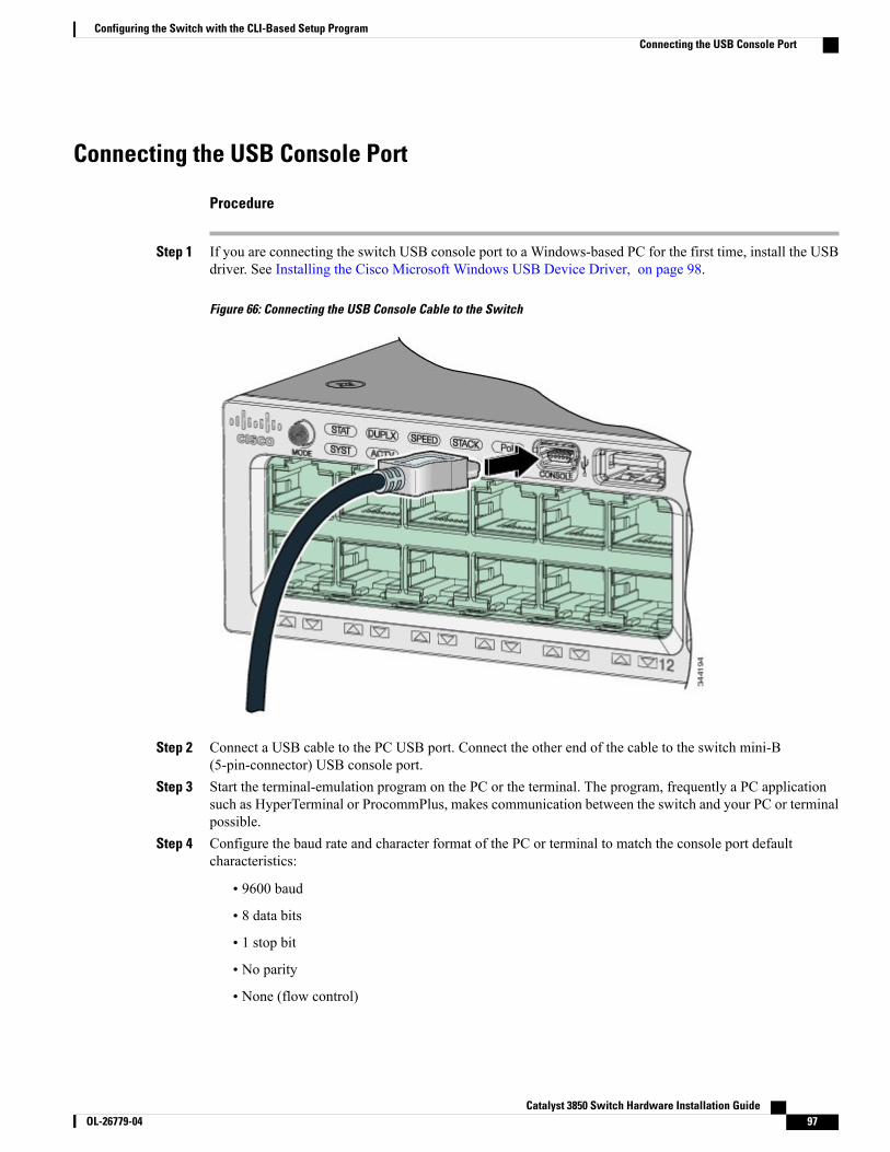
Connecting the USB Console Port
Procedure
Step 1 If you are connecting the switch USB console port to a Windows-based PC for the first time, install the USBdriver. See Installing the Cisco Microsoft Windows USB Device Driver, on page 98.
Figure 66: Connecting the USB Console Cable to the Switch
Step 2 Connect a USB cable to the PC USB port. Connect the other end of the cable to the switch mini-B(5-pin-connector) USB console port.
Step 3 Start the terminal-emulation program on the PC or the terminal. The program, frequently a PC applicationsuch as HyperTerminal or ProcommPlus, makes communication between the switch and your PC or terminalpossible.
Step 4 Configure the baud rate and character format of the PC or terminal to match the console port defaultcharacteristics:
• 9600 baud
• 8 data bits
• 1 stop bit
• No parity
• None (flow control)
Catalyst 3850 Switch Hardware Installation Guide OL-26779-04 97
Configuring the Switch with the CLI-Based Setup ProgramConnecting the USB Console Port
Step 5 Power on the switch as described in the switch getting started guide.Step 6 The PC or terminal displays the bootloader sequence. Press Enter to display the setup prompt. Follow the
steps in the Setup program.
Installing the Cisco Microsoft Windows USB Device DriverA USB device driver must be installed the first time a Microsoft Windows-based PC is connected to the USBconsole port on the switch.
• Installing the Cisco Microsoft Windows XP USB Driver
• Installing the Cisco Microsoft Windows 2000 USB Driver
• Installing the Cisco Microsoft Windows Vista and Windows 7 USB Driver
Installing the Cisco Microsoft Windows XP USB Driver
Procedure
Step 1 Obtain the Cisco USB console driver file from the Cisco.com web site and unzip it.
You can download the driver file from the Cisco.com site for downloading the switch software.Note
Step 2 If using 32-bitWindows XP, double-click the setup.exe file in theWindows_32 folder. If using 64-bitWindowsXP, double-click the setup(x64).exe file in the Windows_64 folder.
Step 3 The Cisco Virtual Com InstallShield Wizard begins.Step 4 The Ready to Install the Program window appears. Click Install.Step 5 The InstallShield Wizard Completed window appears. Click Finish.Step 6 Connect the USB cable to the PC and the switch console port. The USB console port LED turns green, and
the Found New Hardware Wizard appears. Follow the instructions to complete the driver installation.
Installing the Cisco Microsoft Windows 2000 USB Driver
Procedure
Step 1 Obtain the Cisco USB console driver file from the Cisco.com web site and unzip it.
You can download the driver file from the Cisco.com site for downloading the switch software.Note
Catalyst 3850 Switch Hardware Installation Guide98 OL-26779-04
Configuring the Switch with the CLI-Based Setup ProgramInstalling the Cisco Microsoft Windows USB Device Driver
Step 2 Double-click the setup.exe file.Step 3 The Cisco Virtual Com InstallShield Wizard begins. Click Next.Step 4 The Ready to Install the Program window appears. Click Install.Step 5 The InstallShield Wizard Completed window appears. Click Finish.Step 6 Connect the USB cable to the PC and the switch console port. The USB console port LED turns green, and
the Found New Hardware Wizard appears. Follow the instructions to complete the driver installation.
Installing the Cisco Microsoft Windows Vista and Windows 7 USB Driver
Procedure
Step 1 Obtain the Cisco USB console driver file from the Cisco.com web site and unzip it.
You can download the driver file from the Cisco.com site for downloading the switch software.Note
Step 2 If using 32-bit Windows Vista or Windows 7, double-click the setup.exe file in the Windows_32 folder. Ifusing 64-bit Windows Vista or Windows 7, double-click the setup(x64).exe file in the Windows_64 folder.
Step 3 The Cisco Virtual Com InstallShield Wizard begins. Click Next.Step 4 The Ready to Install the Program window appears. Click Install.
If a User Account Control warning appears, clickAllow - I trust this program to proceed.Note
Step 5 The InstallShield Wizard Completed window appears. Click Finish.Step 6 Connect the USB cable to the PC and the switch console port. The USB console port LED turns green, and
the Found New Hardware Wizard appears. Follow the instructions to complete the driver installation.
Uninstalling the Cisco Microsoft Windows USB Driver
Uninstalling the Cisco Microsoft Windows XP and 2000 USB DriverUse the Windows Add or Remove Programs utility or the setup.exe file.
Using the Setup.exe Program
Before You Begin
Disconnect the switch console terminal before uninstalling the driver.
Catalyst 3850 Switch Hardware Installation Guide OL-26779-04 99
Configuring the Switch with the CLI-Based Setup ProgramUninstalling the Cisco Microsoft Windows USB Driver
Procedure
Step 1 Run setup.exe for Windows 32-bit or setup(x64).exe for Windows-64bit. Click Next.Step 2 The InstallShield Wizard for Cisco Virtual Com appears. Click Next.Step 3 When the Program Maintenance window appears, select the Remove radio button. Click Next.Step 4 When the Remove the Program window appears, click Remove.Step 5 When the InstallShield Wizard Completed window appears, click Finish.
Using the Add or Remove Programs Utility
Before You Begin
Disconnect the switch console terminal before uninstalling the driver.
Procedure
Step 1 Click Start > Control Panel > Add or Remove Programs.Step 2 Scroll to Cisco Virtual Com and click Remove.Step 3 When the Program Maintenance window appears, select the Remove radio button. Click Next.
Uninstalling the Cisco Microsoft Windows Vista and Windows 7 USB Driver
Before You Begin
Disconnect the switch console terminal before uninstalling the driver.
Procedure
Step 1 Run setup.exe for Windows 32-bit or setup(x64).exe for Windows-64bit. Click Next.Step 2 The InstallShield Wizard for Cisco Virtual Com appears. Click Next.Step 3 When the Program Maintenance window appears, select the Remove radio button. Click Next.Step 4 When the Remove the Program window appears, click Remove.
If a User Account Control warning appears, clickAllow - I trust this program to proceed.Note
Step 5 When the InstallShield Wizard Completed window appears, click Finish.
Catalyst 3850 Switch Hardware Installation Guide100 OL-26779-04
Configuring the Switch with the CLI-Based Setup ProgramUninstalling the Cisco Microsoft Windows USB Driver
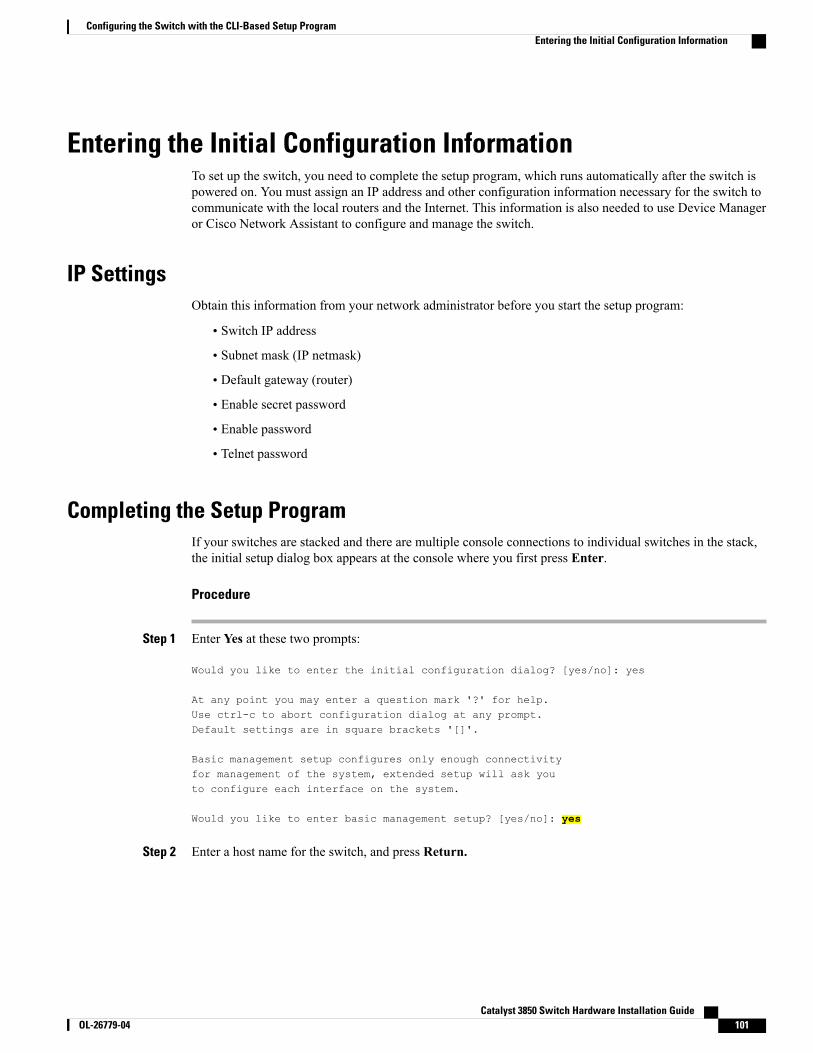
Entering the Initial Configuration InformationTo set up the switch, you need to complete the setup program, which runs automatically after the switch ispowered on. You must assign an IP address and other configuration information necessary for the switch tocommunicate with the local routers and the Internet. This information is also needed to use Device Manageror Cisco Network Assistant to configure and manage the switch.
IP SettingsObtain this information from your network administrator before you start the setup program:
• Switch IP address
• Subnet mask (IP netmask)
• Default gateway (router)
• Enable secret password
• Enable password
• Telnet password
Completing the Setup ProgramIf your switches are stacked and there are multiple console connections to individual switches in the stack,the initial setup dialog box appears at the console where you first press Enter.
Procedure
Step 1 Enter Yes at these two prompts:
Would you like to enter the initial configuration dialog? [yes/no]: yes
At any point you may enter a question mark '?' for help.Use ctrl-c to abort configuration dialog at any prompt.Default settings are in square brackets '[]'.
Basic management setup configures only enough connectivityfor management of the system, extended setup will ask youto configure each interface on the system.
Would you like to enter basic management setup? [yes/no]: yes
Step 2 Enter a host name for the switch, and press Return.
Catalyst 3850 Switch Hardware Installation Guide OL-26779-04 101
Configuring the Switch with the CLI-Based Setup ProgramEntering the Initial Configuration Information
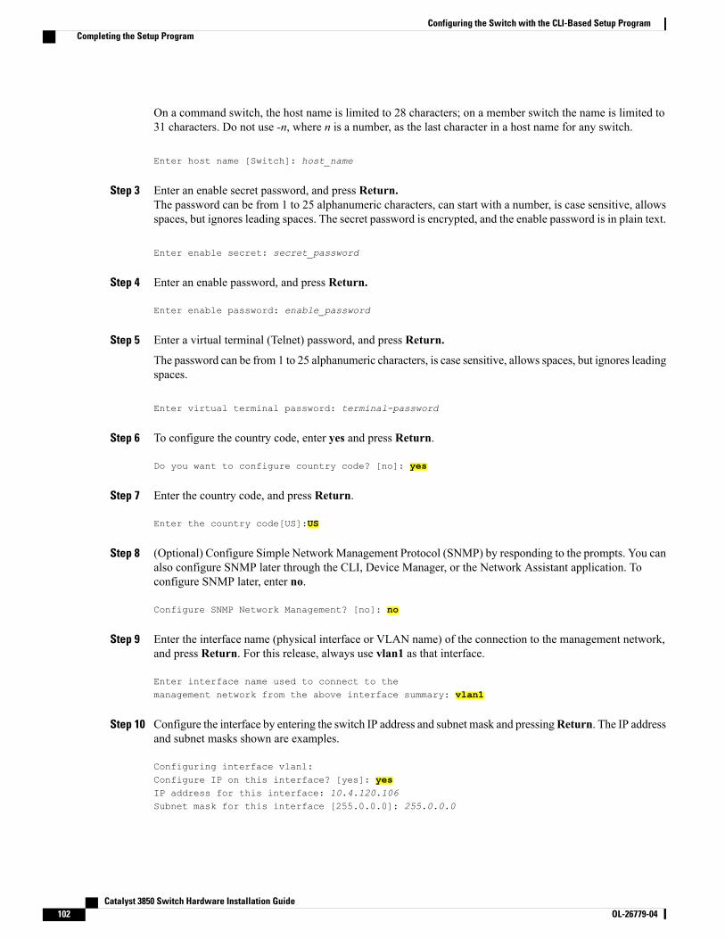
On a command switch, the host name is limited to 28 characters; on a member switch the name is limited to31 characters. Do not use -n, where n is a number, as the last character in a host name for any switch.
Enter host name [Switch]: host_name
Step 3 Enter an enable secret password, and press Return.The password can be from 1 to 25 alphanumeric characters, can start with a number, is case sensitive, allowsspaces, but ignores leading spaces. The secret password is encrypted, and the enable password is in plain text.
Enter enable secret: secret_password
Step 4 Enter an enable password, and press Return.
Enter enable password: enable_password
Step 5 Enter a virtual terminal (Telnet) password, and press Return.
The password can be from 1 to 25 alphanumeric characters, is case sensitive, allows spaces, but ignores leadingspaces.
Enter virtual terminal password: terminal-password
Step 6 To configure the country code, enter yes and press Return.
Do you want to configure country code? [no]: yes
Step 7 Enter the country code, and press Return.
Enter the country code[US]:US
Step 8 (Optional) Configure Simple Network Management Protocol (SNMP) by responding to the prompts. You canalso configure SNMP later through the CLI, Device Manager, or the Network Assistant application. Toconfigure SNMP later, enter no.
Configure SNMP Network Management? [no]: no
Step 9 Enter the interface name (physical interface or VLAN name) of the connection to the management network,and press Return. For this release, always use vlan1 as that interface.
Enter interface name used to connect to themanagement network from the above interface summary: vlan1
Step 10 Configure the interface by entering the switch IP address and subnet mask and pressingReturn. The IP addressand subnet masks shown are examples.
Configuring interface vlan1:Configure IP on this interface? [yes]: yesIP address for this interface: 10.4.120.106Subnet mask for this interface [255.0.0.0]: 255.0.0.0
Catalyst 3850 Switch Hardware Installation Guide102 OL-26779-04
Configuring the Switch with the CLI-Based Setup ProgramCompleting the Setup Program
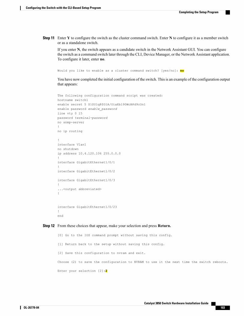
Step 11 Enter Y to configure the switch as the cluster command switch. Enter N to configure it as a member switchor as a standalone switch.
If you enter N, the switch appears as a candidate switch in the Network Assistant GUI. You can configurethe switch as a command switch later through the CLI, DeviceManager, or the Network Assistant application.To configure it later, enter no.
Would you like to enable as a cluster command switch? [yes/no]: no
You have now completed the initial configuration of the switch. This is an example of the configuration outputthat appears:
The following configuration command script was created:hostname switch1enable secret 5 $1$Ulq8$DlA/OiaEbl90WcBPd9cOn1enable password enable_passwordline vty 0 15password terminal-passwordno snmp-server!no ip routing
!interface Vlan1no shutdownip address 10.4.120.106 255.0.0.0!interface GigabitEthernet1/0/1!interface GigabitEthernet1/0/2
interface GigabitEthernet1/0/3!...<output abbreviated>!
interface GigabitEthernet1/0/23!end
Step 12 From these choices that appear, make your selection and press Return.
[0] Go to the IOS command prompt without saving this config.
[1] Return back to the setup without saving this config.
[2] Save this configuration to nvram and exit.
Choose (2) to save the configuration to NVRAM to use it the next time the switch reboots.
Enter your selection [2]:2
Catalyst 3850 Switch Hardware Installation Guide OL-26779-04 103
Configuring the Switch with the CLI-Based Setup ProgramCompleting the Setup Program

The switch now runs this default configuration. If you want to change this configuration or perform othermanagement tasks, see Management Options, on page 24.
Catalyst 3850 Switch Hardware Installation Guide104 OL-26779-04
Configuring the Switch with the CLI-Based Setup ProgramCompleting the Setup Program