Embed Size (px)
Citation preview
1
TECHNICAL
October 2016 EDITION I
S LINE SILENT pipes and fittings
catalogue
CONTENTGENERAL REMARKS 2 2
ABOUT THE COMPANY 5
1. STANDARDS APPLICABLE TO PEŠTAN HT (PP) PIPES AND FITNG 6
2. BASIC INFORMATION ON PEŠTAN PP PIPES AND FITTING 7 2.1 Marking of pipes 8 8
2.2 Marking of the fitting 8 2.3 Production program 9
3. PACKAGING, TRANSPORT AND STORAGE 10 3.1 Packaging and pipe fittings 10
3.2 Transport and handling 11 3.3 Storage 12 4. INSTALLATION AND CONNECTION 14 4.1 Types of pipeline 14
4.2 Connecting pipes and fittings 16 4.3 Reliance pipeline 17
4.4 Oslanjanje cevovoda 18 4.5 Penetration of pipes through the ceiling 19 4.6 Installing the pipe in concrete 19 4.7 Installation of the device to prevent flooding in buildings 19 4.8 Measures to reduce noise 20
4.9 Firefighting measures 20 4.10 Testing of the pipeline 21
5. USE OF PIPELINES 22
6. DISPOSAL OF INTERFERENCE 29
7. MAINTENANCE 29
8. REMOVAL AND DISPOSAL 30
9. PROCEDURE IN POSTUSAGE 30
10. LIST OF ABBREVIATIONS 31
11. TABLE OF CHEMICAL RESISTANCE 32 11.1 Introduction 32
11.2 Scope 32 11.3 Definitions and symbols as abbreviations 32
12. CERTIFICATES 41
13. PRODUCTION PROGRAM 43
3
GENERAL REMARKS
Technical catalog is subject to change in certain intervals as a result of the adoption of new products and modifications thereof. For that reason it is necessary to check whether you have the latest version of technical catalog. Date of issue technical catalog is on the cover of a catalog of the latest version it can be downloaded from Site www.pestan.net or request via email [email protected].
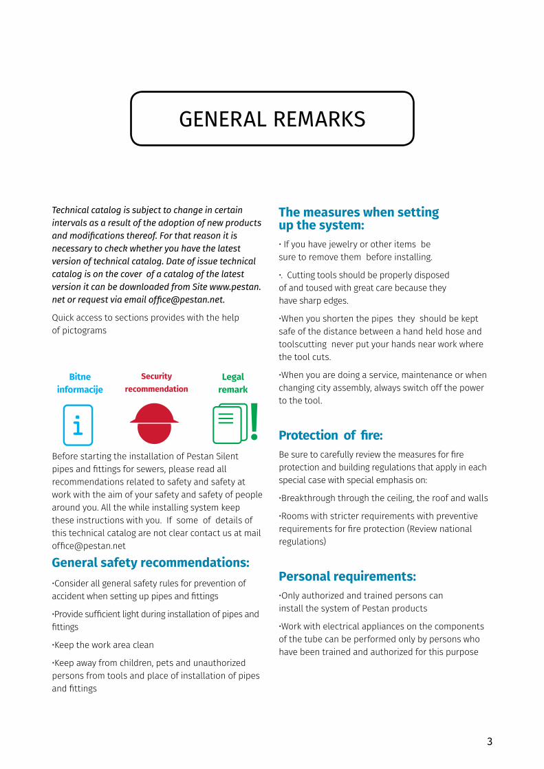
Quick access to sections provides with the help of pictograms
Before starting the installation of Pestan Silent pipes and fittings for sewers, please read all recommendations related to safety and safety at work with the aim of your safety and safety of people around you. All the while installing system keep these instructions with you. If some of details of this technical catalog are not clear contact us at mail [email protected]
General safety recommendations:•Consider all general safety rules for prevention ofaccident when setting up pipes and fittings
•Provide sufficient light during installation of pipes andfittings
•Keep the work area clean
•Keep away from children, pets and unauthorizedpersons from tools and place of installation of pipesand fittings
The measures when setting up the system:• If you have jewelry or other items besure to remove them before installing.
•. Cutting tools should be properly disposed of and toused with great care because they have sharp edges.
•When you shorten the pipes they should be keptsafe of the distance between a hand held hose andtoolscutting never put your hands near work wherethe tool cuts.
•When you are doing a service, maintenance or whenchanging city assembly, always switch off the powerto the tool.
Protection of fire:Be sure to carefully review the measures for fire protection and building regulations that apply in each special case with special emphasis on:
•Breakthrough through the ceiling, the roof and walls
•Rooms with stricter requirements with preventiverequirements for fire protection (Review nationalregulations)
Personal requirements: •Only authorized and trained persons caninstall the system of Pestan products
•Work with electrical appliances on the componentsof the tube can be performed only by persons whohave been trained and authorized for this purpose
Bitne informacije
Security recommendation
Legal remark
4

5
ABOUT US
Private companie Peštan is a leader in the Balkan in the production of plastic pipes and fittings for water, sewer and gas. The company was establised in 1989 and has been producing water pipes made of polyethylene. Over time, introduced with new materials (polypropylene and PVC) and expanded production program. Today the offer can be found over 5000 products ranging from pipes and fittings and PVC profiles, through luxury and modern drains, to tape for irrigation. Production facilities are located in 70 km south of Arandjelovac from Belgrade, and foreign missions in countries in the region:Bosnia and Herzegovina, Romania, Croatia and the Ukraine and UAE.
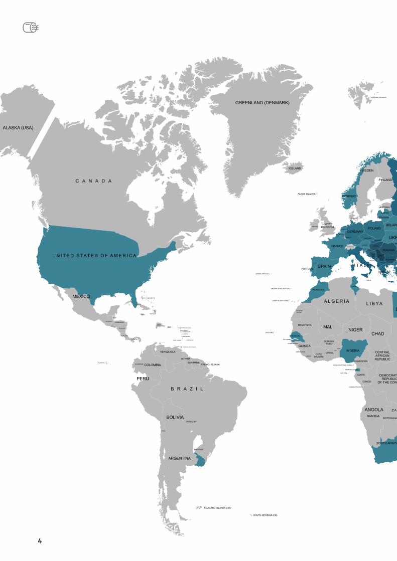
The company is present in the market of Europe, Russia, Middle East, North Africa, Latin America and the United States.Export-oriented and sales implemented in over 60 countries of the world!
PEŠTAN the organization and operations of the Company established and certified to the requirements of the Integrated System management
- The quality management ISO 9001 (since 2004) - Environmental management, ISO 14001 (from 2010 g) - Management of Occupational Health and Safety OHSAS 18001 (since 2010.g)
PEŠTAN products certified by an appropriate normative regulations with the most eminent certification Body: DVGW, MPA, SABS, BULGARKONTROLA, blanket, IGH, BJW, VUSAPL, ICC, SKZ, EMI ... In order to meet the needs of as many customers, the company is constantly innovating and improving personnel and equipment. Since 2009, the company introduced the SAP ERP modules MM, SD, PP, CO Fi and a since 2012. year they expanded functionality and WMS. Introduction WCM and WMS system has increased efficiency, contributed to deployment costs and professional maintenance. Since 2015, SAP has been implemented in the management module Quality Management (QM).
Employees of Peštan which has over 1000, the joint efforts of the company justify the slogan:
6
STANDARDS
SRPS EN 681-1:2007 Elastomerne zaptivke - Zahtevi za materijale zaptivki spojeva na cevovodima namenjenim za dovod i odvod vode - Deo 1: Guma
EN 681-1:1996/A3:2005 Elastomeric seals - Material requirements for pipe joint seals used in water and drainage applications - Part 1: Vulcanized rubber
SRPS EN 12056-1:2011 Gravitacioni sistemi za odvođenje otpadne vode u objektima - Deo 1: Opšti zahtevi i zahtevi za performanse
EN 12056-1:2000 Gravity drainage systems inside buildings - Part 1: General and performance requirements
SRPS EN 12056-2:2011 Gravitacioni sistemi za odvođenje otpadne vode u objektima - Deo 2: Sanitarna cevna mreža, plan i proračun
EN 12056-2:2000 Gravity drainage systems inside buildings - Part 2: Sanitary pipework, layout and calculation
SRPS EN 12056-3:2011 Gravitacioni sistemi za odvođenje otpadne vode u objektima - Deo 3: Odvodnjavanje krova, plan i proračun
EN 12056-3:2000 Gravity drainage systems inside buildings - Part 3: Roof drainage, layout and calculation
SRPS EN 12056-4:2011 Gravitacioni sistemi za odvođenje otpadne vode u objektima - Deo 4: Pumpne stanice za otpadnu vodu - Plan i proračun
EN 12056-4:2000 Gravity drainage systems inside buildings - Part 4: Wastewater lifting plants - Layout and calculation
SRPS EN 12056-5:2011 Gravitacioni sistemi za odvodnjavanje otpadne vode u objektima – Deo 5: Ugradnja i ispitivanje, uputstva za upravljanje, održavanje i upotreba
EN 12056-4:2000 Gravity drainage systems inside buildings - Part 5: Installation and testing, instructions for operation, maintenance and use
SRPS EN 1411:2008 Sistemi cevovoda i kanali od plastičnih masa - Termoplastične cevi - Određivanje otpornosti na spoljne udare stepenastom metodom
EN 1411:1996 Plastics piping and ducting systems - Thermoplastics pipes - Determination of resistance to external blows by the staircase method
SRPS EN 14366:2008 Laboratorijska merenja buke od instalacija za otpadne vode
EN 14366:2004 Laboratory measurement of noise from waste water installations
SRPS EN 1451-1:2008 Sistemi cevovoda od plastičnih masa za odvođenje zaprljanih i otpadnih voda (niske i visoke temperature) unutar građevinskih konstrukcija - Polipropilen (PP) - Deo 1: Specifikacije za cevi, fitinge i sistem
EN 1451-1:1998 Plastics piping systems for soil and waste discharge (low and high temperature) within the building structure - Polypropylene (PP) - Part 1: Specifications for pipes, fittings and the system
SRPS EN ISO 3126:2009 Sistemi cevovoda od plastičnih masa - Komponente od plastičnih masa - Određivanje dimenzija
EN ISO 3126:2005 Plastics piping systems - Plastics components - Determination of dimensions
SRPS EN 744:2008 Sistemi cevovoda i kanala od plastičnih masa - Termoplastične cevi - Metoda ispitivanja otpornosti na spoljneudare obodnom metodom
EN 744:1995 Plastics piping and ducting systems - Thermoplastics pipes - Test method for resistance to external blows by the round-the-clock method
SRPS EN ISO 2505:2013 Termoplastične cevi — Dimenzionalna stabilnost pri zagrevanju — Metoda ispitivanja i parametri
EN ISO 2505:2005 Thermoplastics pipes - Longitudinal reversion - Test method and parameters
SRPS EN ISO 1133-1:2013 Plastične mase – Određivanje masenog protoka rastopa (MFR) i zapreminskog protoka rastopa (MVR) termoplasta – Deo 1: Standardna metoda
ISO 1133-1:2011 Plastics - Determination of the melt mass-flow rate (MFR) and melt volume-flow rate (MVR) of thermoplastics - Part 1: Standard method
SRPS EN ISO 580:2009 Sistemi cevovoda i kanala od plastičnih masa - Injekciono presovani termoplastični fitinzi - Metode za vizuelnu procenu efekata zagrevanja
ISO 580:2005 Plastics piping and ducting systems - Injection-moulded thermoplastics fittings - Methods for visually assessing the effects of heating
SRPS EN 1053:2008 Sistemi cevovoda od plastičnih masa - Termoplastični nepritisni sistemi cevovoda - Metoda ispitivanja vodonepropusnosti
EN 1053:1995 Plastics piping systems - Thermoplastics piping systems for non-pressure applications - Test method for watertightness
STANDARDS APPLICABLE
ON PEŠTAN silent PIPES AND FITNG
1
7
INFORMATIONBasic information about S LINE pipes and fittings
The program of S LINE pipes and fittings from the company Peštan is produced from PP-C (polypropylene copolymers) by latest technology extrusion three-layer tubes per the requirements of European Standard 1451. The latest technology of three-layer extrusion of pipes and modified mineral materials additives, have raised the system of draining contaminated and waste water within the building structure to a higher level. Recyclable without loss of mechanical properties of polypropylene make ecologically suitable material.
Pipes and fittings from S LINE Pestan production programs are intended for soil and waste
discharge (low and high temperature) within the building structure. S LINE system is universal and it can be used for drainage of contaminated water, for one-floor houses to large multiple floor buildings.
Installation and manipulation of elements of the pipeline is very simple and it is described in the forthcoming chapters of this technical catalogue. Connecting pipes are made via the connecting elements, the fitting, while the water tightness is provided with rubber sealing rings. Inner layer of polypropylene sewage pipes has a very low roughness, resulting in good hydraulic characteristics, high resistance to abrasion, as well as to the retention of sediments and bacterial cultures for the inner wall of the pipe. For easier inspection of pipeline, inner layer of pipe is made in white colour.
S LINE pipes and fitting are resistant to corrosion and their lifespan is over 50 years. Pipes and fittings possess exceptional thermal stability and they are resistant to: • short thermal loads of hot waterof up to 95 ° C (30 seconds / day)• continuously up to 60 ° C (5hrs / day = 87,600 hrs/ 50 years)In terms of chemical resistance HT (PP) LOW NOISE pipes are resistant to: salt water, alcohol, acids, alkalis, sulphates, aggressive gas and all kinds of detergents. They are suitable for drainage of aggressive chemical waste, pH value of 2 (for very acid waste water) to 12 (for a very base wastewater).HT (PP) LOW NOISE program is sensitive to waste water containing a high percentage of gasoline (petrol), benzene or acetone. For a detailed chemical
resistance pipeline look at table of chemical resistance, which is an integral part of this technical catalogue. Connection of pipes and fittings are 100% resistant to leakage up to pressure of 0.5bar (5m water pillar). The pipes are not intended for outdoor use due long-term volatility during UV radiation. Also pipes are not intended for installation in the ground. It is not advisable to perform installation of pipelines on temperatures below 5 ° C. Polypropylene has excellent sound and thermal insulating properties (far better than eg. steel). In terms of fire protection, HT (PP) LOW NOISE pipes program belongs to flammability class B2 of DIN 4102, they belong to a group of normally flammable materials.
Peštan S LINE production program pipe includes:
• S LINE pipe diameter 32,40,50,75,90,110,125 and160 with one socket
• S LINE pipe diameter 32,40,50,75,90,110,125 and160 with double socket
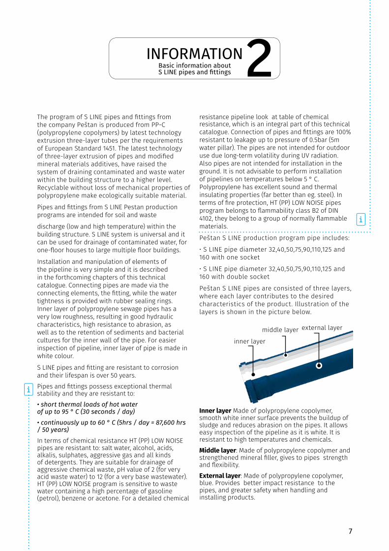
Peštan S LINE pipes are consisted of three layers, where each layer contributes to the desired characteristics of the product. Illustration of the layers is shown in the picture below.
2
Inner layer Made of polypropylene copolymer, smooth white inner surface prevents the buildup of sludge and reduces abrasion on the pipes. It allows easy inspection of the pipeline as it is white. It is resistant to high temperatures and chemicals.Middle layer: Made of polypropylene copolymer and strengthened mineral filler, gives to pipes strength and flexibility.External layer: Made of polypropylene copolymer, blue. Provides better impact resistance to the pipes, and greater safety when handling and installing products.
inner layer
middle layer external layer
8
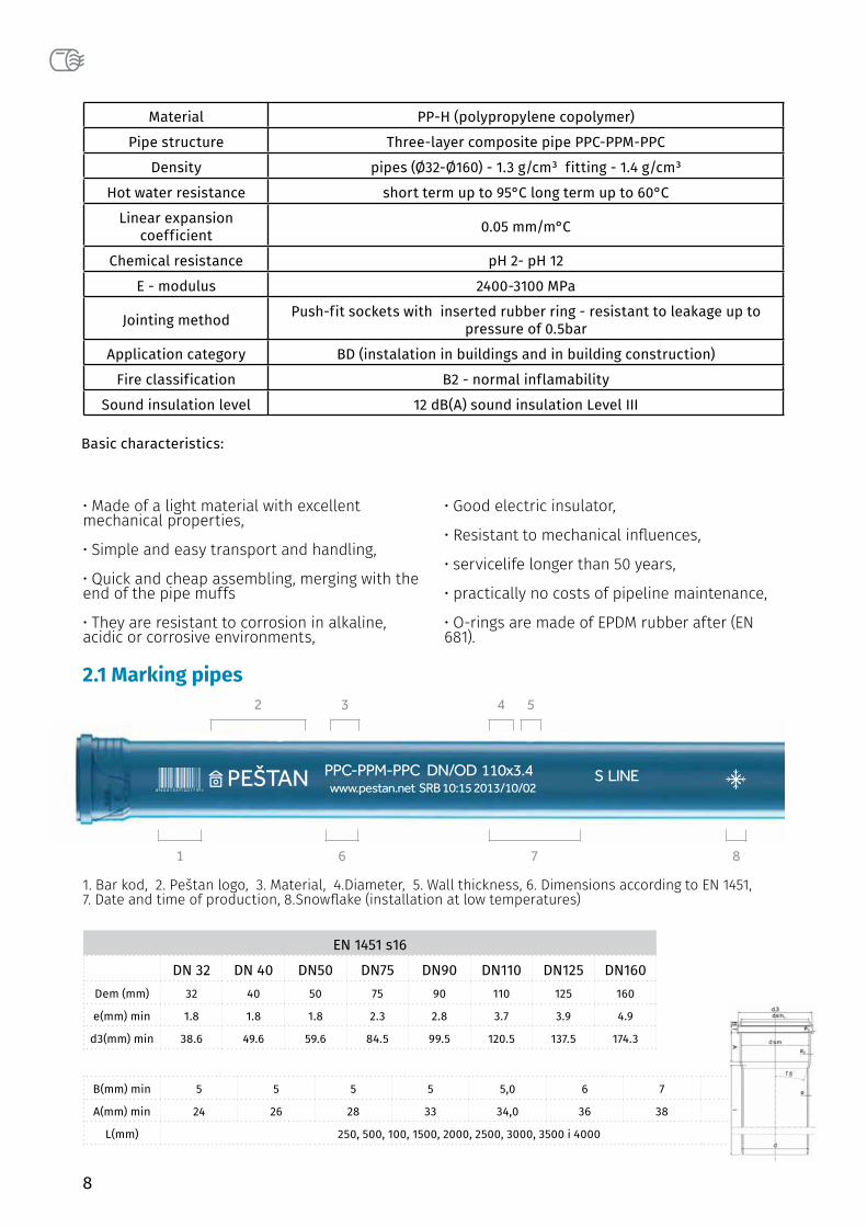
EN 1451 s16
DN 32 DN 40 DN50 DN75 DN90 DN110 DN125 DN160Dem (mm) 32 40 50 75 90 110 125 160
e(mm) min 1.8 1.8 1.8 2.3 2.8 3.7 3.9 4.9
d3(mm) min 38.6 49.6 59.6 84.5 99.5 120.5 137.5 174.3
B(mm) min 5 5 5 5 5,0 6 7 9
A(mm) min 24 26 28 33 34,0 36 38 41
L(mm) 250, 500, 100, 1500, 2000, 2500, 3000, 3500 i 4000
2.1 Marking pipes2 3 4 5
6 71 8
PPC-PPM-PPC DN/OD 110x3.4 S LINE www.pestan.net SRB 10:15 2013/10/02PEŠTAN
1. Bar kod, 2. Peštan logo, 3. Material, 4.Diameter, 5. Wall thickness, 6. Dimensions according to EN 1451,7. Date and time of production, 8.Snowflake (installation at low temperatures)
Basic characteristics:
• Made of a light material with excellentmechanical properties,
• Simple and easy transport and handling,
• Quick and cheap assembling, merging with theend of the pipe muffs
• They are resistant to corrosion in alkaline,acidic or corrosive environments,
• Good electric insulator,
• Resistant to mechanical influences,
• servicelife longer than 50 years,
• practically no costs of pipeline maintenance,
• O-rings are made of EPDM rubber after (EN681).
Material PP-H (polypropylene copolymer)
Pipe structure Three-layer composite pipe PPC-PPM-PPC
Density pipes (Ø32-Ø160) - 1.3 g/cm³ fitting - 1.4 g/cm³
Hot water resistance short term up to 95°C long term up to 60°C
Linear expansion coefficient 0.05 mm/m°C
Chemical resistance pH 2- pH 12
E - modulus 2400-3100 MPa
Jointing method Push-fit sockets with inserted rubber ring - resistant to leakage up to pressure of 0.5bar
Application category BD (instalation in buildings and in building construction)
Fire classification B2 - normal inflamability
Sound insulation level 12 dB(A) sound insulation Level III
9
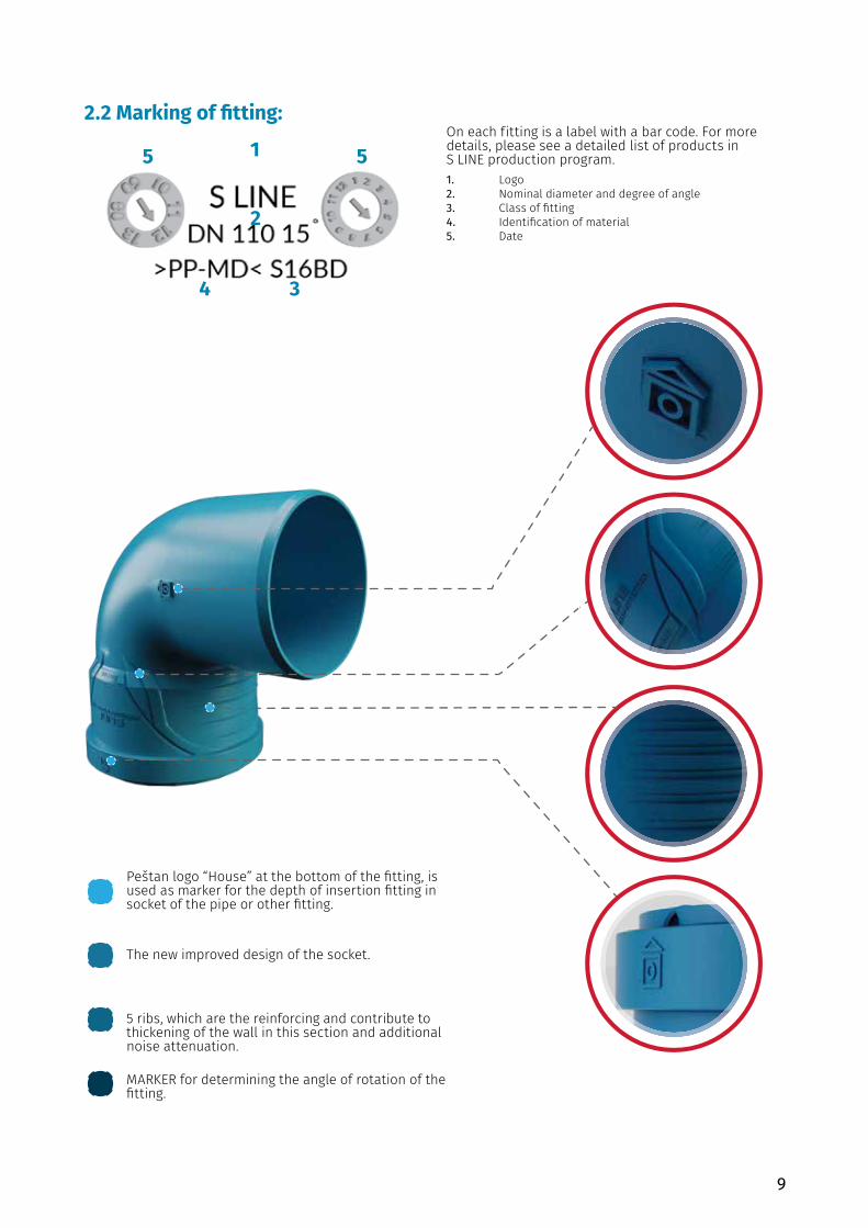
On each fitting is a label with a bar code. For more details, please see a detailed list of products in S LINE production program.1. Logo2. Nominal diameter and degree of angle3. Class of fitting4. Identification of material5. Date
2.2 Marking of fitting:
Peštan logo “House” at the bottom of the fitting, is used as marker for the depth of insertion fitting in socket of the pipe or other fitting.
The new improved design of the socket.
5 ribs, which are the reinforcing and contribute to thickening of the wall in this section and additional noise attenuation.
MARKER for determining the angle of rotation of the fitting.
1
2
5 5
4 3
10
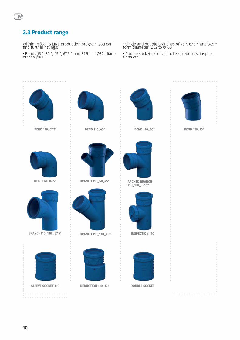
Within Peštan S LINE production program ,you can find further fittings:• Bends 15 °, 30 °, 45 °, 67.5 ° and 87.5 ° of Ø32 diam-eter to Ø160
• Single and double branches of 45 °, 67.5 ° and 87.5 °form diameter Ø32 to Ø160• Double sockets, sleeve sockets, reducers, inspec-tions etc ...
BEND 110_67.5°
BRANCH 110_50_45°HTB BEND 87.5°
BRANCH 110_110_45°
REDUCTION 110_125
BEND 110_45° BEND 110_30°
ARCHED BRANCH 110_110_ 87.5°
INSPECTION 110
DOUBLE SOCKET
BEND 110_15°
BRANCH110_110_ 87.5°
SLEEVE SOCKET 110
2.3 Product range
11
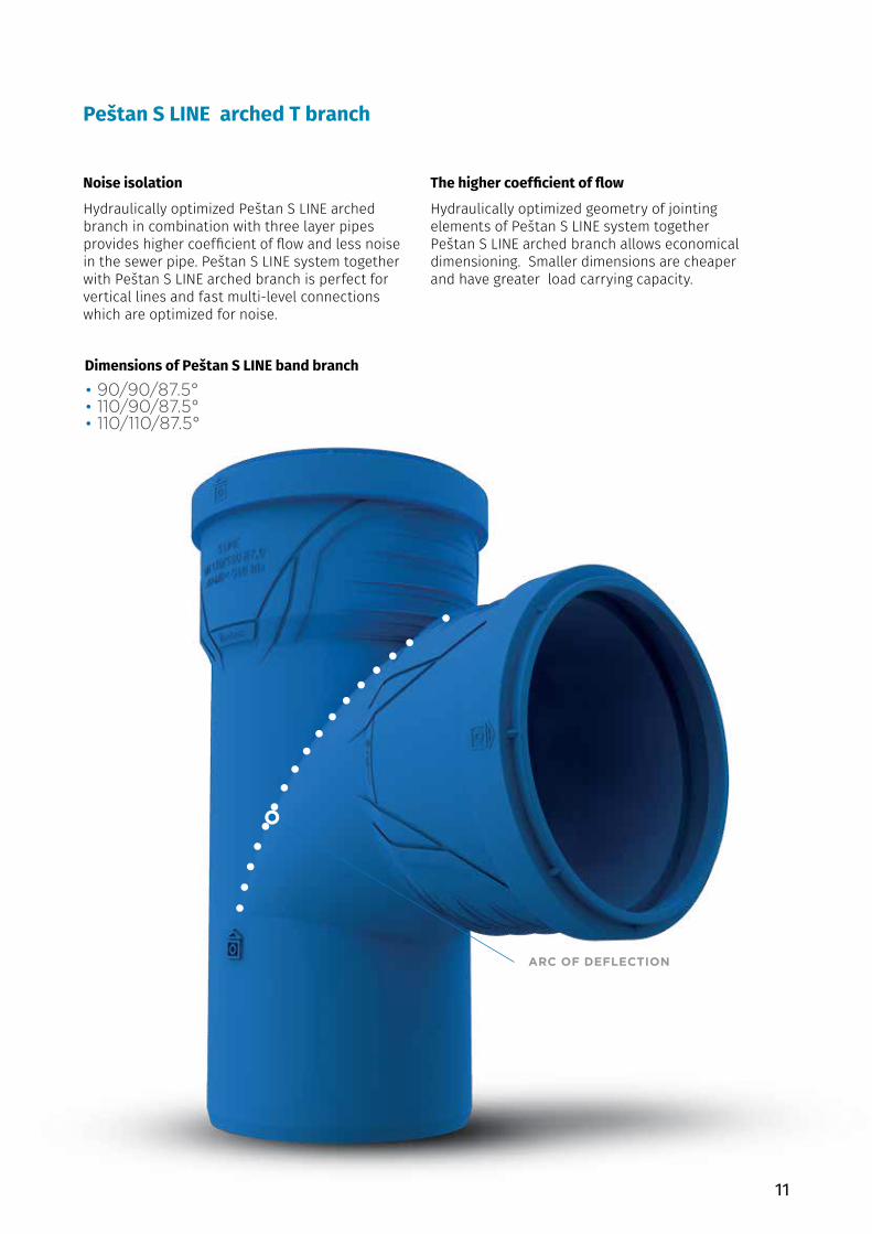
ARC OF DEFLECTION
Peštan S LINE arched T branch
Dimensions of Peštan S LINE band branch• 90/90/87.5°• 110/90/87.5°• 110/110/87.5°
Noise isolation
Hydraulically optimized Peštan S LINE arched branch in combination with three layer pipes provides higher coefficient of flow and less noise in the sewer pipe. Peštan S LINE system together with Peštan S LINE arched branch is perfect for vertical lines and fast multi-level connections which are optimized for noise.
The higher coefficient of flow
Hydraulically optimized geometry of jointing elements of Peštan S LINE system together Peštan S LINE arched branch allows economical dimensioning. Smaller dimensions are cheaper and have greater load carrying capacity.
12
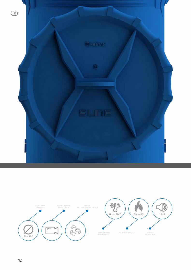
AVAILABLE PROFILES
32 - 160
EASY CAMERA INSPECTION
WHITEANTIBACTERIAL LAYER
TEMPERATURERESISTANCE
Up to 60°C
COMBUSTIBILITY
Class B2
SOUND ISOLATION
12dB
13
PACKINGPACKING,
TRANSPORT AND STORAGE
Peštan S LINE pipes and fittings are packed in transport packages (unit and pallet) in a manner favorable to customers. The way of packaging ensures safety to a customer when they do storage and easy handling of the same.
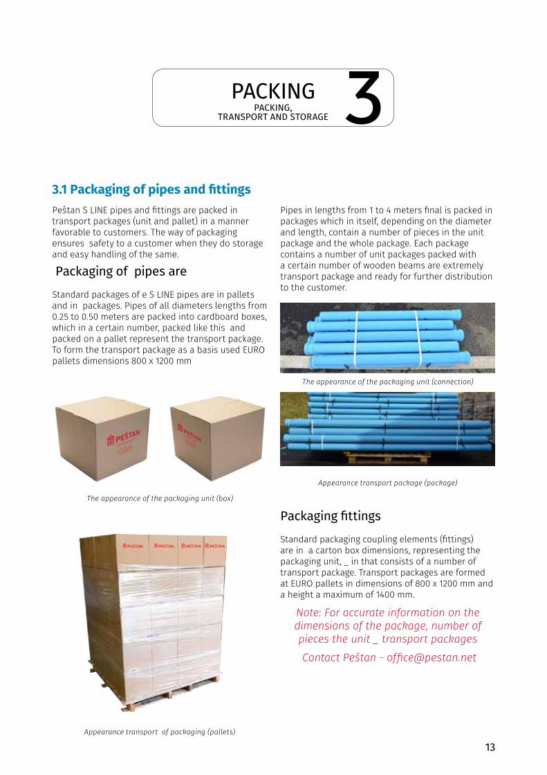
Packaging of pipes are Standard packages of e S LINE pipes are in pallets and in packages. Pipes of all diameters lengths from 0.25 to 0.50 meters are packed into cardboard boxes, which in a certain number, packed like this and packed on a pallet represent the transport package. To form the transport package as a basis used EURO pallets dimensions 800 x 1200 mm
Pipes in lengths from 1 to 4 meters final is packed in packages which in itself, depending on the diameter and length, contain a number of pieces in the unit package and the whole package. Each package contains a number of unit packages packed with a certain number of wooden beams are extremely transport package and ready for further distribution to the customer.
Packaging fittings Standard packaging coupling elements (fittings) are in a carton box dimensions, representing the packaging unit, _ in that consists of a number of transport package. Transport packages are formed at EURO pallets in dimensions of 800 x 1200 mm and a height a maximum of 1400 mm.
Note: For accurate information on the dimensions of the package, number of pieces the unit _ transport packages Contact Peštan - [email protected]
The appearance of the packaging unit (box)
The appearance of the packaging unit (connection)
Appearance transport package (package)
Appearance transport of packaging (pallets)
3.1 Packaging of pipes and fittings
3
14
Pestan S LINE pipes and joint elements are transported by suitable vehicles. Loading space of the vehicle must be clear, without any residuals, flat and without sharp lumps (on floor and on the sides of the inner loading part of the vehicle).
Dimensions of pallets and packages are made so the space can be used to the maximum.
When we talk about loading of the transport packages (both pipes and joints) in card board boxes packages are designed so that in the cargo space of height of 2.9m can be placed 2 packages one on to of another.
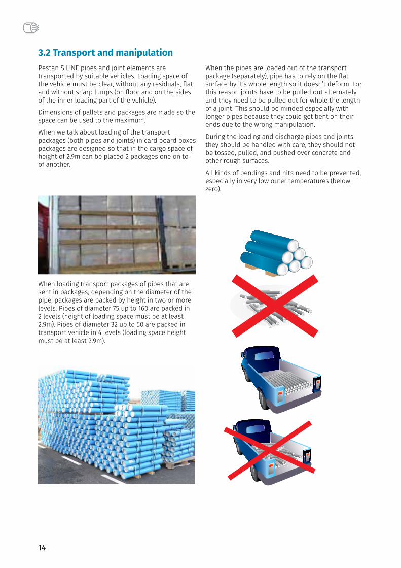
When loading transport packages of pipes that are sent in packages, depending on the diameter of the pipe, packages are packed by height in two or more levels. Pipes of diameter 75 up to 160 are packed in 2 levels (height of loading space must be at least 2.9m). Pipes of diameter 32 up to 50 are packed in transport vehicle in 4 levels (loading space height must be at least 2.9m).
When the pipes are loaded out of the transport package (separately), pipe has to rely on the flat surface by it’s whole length so it doesn’t deform. For this reason joints have to be pulled out alternately and they need to be pulled out for whole the length of a joint. This should be minded especially with longer pipes because they could get bent on their ends due to the wrong manipulation.
During the loading and discharge pipes and joints they should be handled with care, they should not be tossed, pulled, and pushed over concrete and other rough surfaces.
All kinds of bendings and hits need to be prevented, especially in very low outer temperatures (below zero).
3.2 Transport and manipulation
15
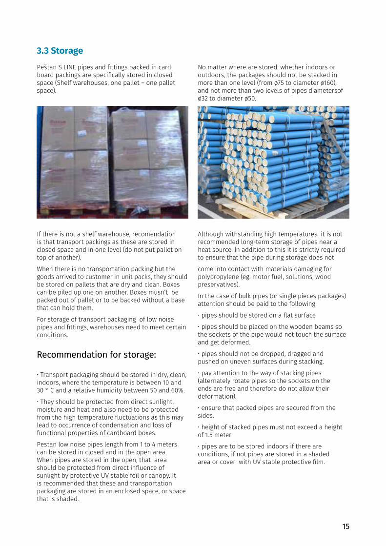
3.3 StoragePeštan S LINE pipes and fittings packed in card board packings are specifically stored in closed space (Shelf warehouses, one pallet – one pallet space).
If there is not a shelf warehouse, recomendation is that transport packings as these are stored in closed space and in one level (do not put pallet on top of another).
When there is no transportation packing but the goods arrived to customer in unit packs, they should be stored on pallets that are dry and clean. Boxes can be piled up one on another. Boxes musn’t be packed out of pallet or to be backed without a base that can hold them.
For storage of transport packaging of low noise pipes and fittings, warehouses need to meet certain conditions.
Recommendation for storage:
• Transport packaging should be stored in dry, clean,indoors, where the temperature is between 10 and30 ° C and a relative humidity between 50 and 60%.
• They should be protected from direct sunlight,moisture and heat and also need to be protectedfrom the high temperature fluctuations as this maylead to occurrence of condensation and loss offunctional properties of cardboard boxes.
Pestan low noise pipes length from 1 to 4 meters can be stored in closed and in the open area. When pipes are stored in the open, that area should be protected from direct influence of sunlight by protective UV stable foil or canopy. It is recommended that these and transportation packaging are stored in an enclosed space, or space that is shaded.
No matter where are stored, whether indoors or outdoors, the packages should not be stacked in more than one level (from ø75 to diameter ø160), and not more than two levels of pipes diametersof ø32 to diameter ø50.
Although withstanding high temperatures it is not recommended long-term storage of pipes near a heat source. In addition to this it is strictly required to ensure that the pipe during storage does not
come into contact with materials damaging for polypropylene (eg. motor fuel, solutions, wood preservatives).
In the case of bulk pipes (or single pieces packages) attention should be paid to the following:
• pipes should be stored on a flat surface
• pipes should be placed on the wooden beams sothe sockets of the pipe would not touch the surfaceand get deformed.
• pipes should not be dropped, dragged andpushed on uneven surfaces during stacking.
• pay attention to the way of stacking pipes(alternately rotate pipes so the sockets on theends are free and therefore do not allow theirdeformation).
• ensure that packed pipes are secured from thesides.
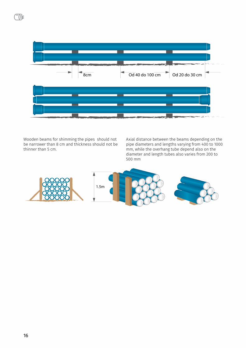
• height of stacked pipes must not exceed a heightof 1.5 meter
• pipes are to be stored indoors if there areconditions, if not pipes are stored in a shadedarea or cover with UV stable protective film.
16
Wooden beams for shimming the pipes should not be narrower than 8 cm and thickness should not be thinner than 5 cm.
Axial distance between the beams depending on the pipe diameters and lengths varying from 400 to 1000 mm, while the overhang tube depend also on the diameter and length tubes also varies from 200 to 500 mm
17
INSTALLATIONINSTALLATION AND CONNECTION
Peštan S LINE pipes and fittings are installed in accordance with EN 12056 Gravity drainage systems inside buildings.
If there is a specific regulation within certain countries, which deviates from the norms mentioned, be sure to consult Peštan before installing.
4.1 Types of pipelinesTo properly comprehend the connection and installation of interior installations for drainage of used water is necessary to explain the types of pipelines, which are part of a system for drainage of water use. The main classification of pipelines is as follows:
Connecting line from building to the street This connection line is a line that leads from the building to terminal on a street circuit. It should be as short as possible and straighter.
Connecting line for the places where water is flowing Connecting line is a pipeline to connect the pouring places (VC cup, bidet, sink, ...). Diameter of pipeline defines a number and type of the pouring places to join him. Connecting cables are mainly installed in grooves, in the walls and floors and closed with mortar or sleeve. The lines of this type can be installed in specially designated channels and can be closed by prefabricated elements, allowing easier access to the pipeline system when changing. Connecting lines also can be hung under the plate, that means for the ceiling of the room, which is located below, via clamps.
There is another way of installing the connecting piping, which is mounting in cavity walls (plaster sandwich walls) and hanging by clips for constructive elements of sandwich walls. Connecting lines must not be longer than 3 m and must have a fall of minimum 3%. Connecting seats with the
casting pipeline is realized via a siphon to prevent the return of odours from the sewage network. Connecting lines should be as short as possible and straighter.
The vertical line (“vertical”) The vertical line is placed vertically (so it got its name) and its purpose is to connect the first type of connecting lines with a second type of connection line. Pestan recommends the use of non-return valves at the connection places. Lines of this type are usually placed inside the walls and closed with mortar or placed in channels, relying on clamps. Placing pipes in the trench allows easier access to the pipeline for maintenance. In the case of plastic piping connections between the vertical line and the connection line is realized through two elbow of 45 .̊ In buildings with more than three floors, cascade is installed to vertical pipe in order to reduce water consumption. Cascade is performed so as to draw the line elbow angle of 90˚ in the length of 250 mm, than it comes back in the vertical direction by elbow at an angle of 90 .̊ Before elbow, reducer is being installed and after restoring water into vertical direction and by reducing piece returns to its original diameter. In this way, excessive force of water is avoided which would occur at the connecting point of the vertical and the connection line.
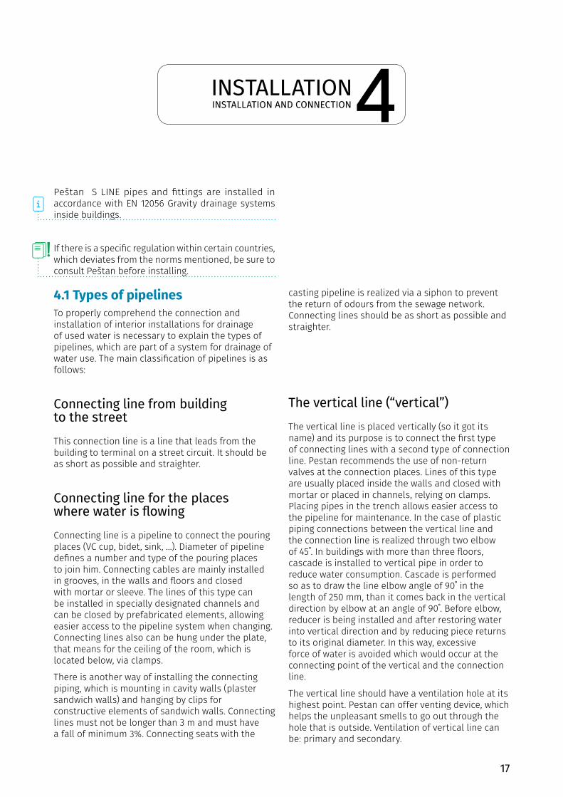
The vertical line should have a ventilation hole at its highest point. Pestan can offer venting device, which helps the unpleasant smells to go out through the hole that is outside. Ventilation of vertical line can be: primary and secondary.
4
18
Showing vertically withprimary ventilation
Showing vertically withsecundary ventilation
Showing vertically withsecundary ventilation
Ventilation at large buildings
VENTILATION
ROOF ROOF
3rd floor
3rd floor 12th floor
8th floor
4th floor
3rd floor
SECONDARY VENTILATION,PRIMARY VENTILATION
PRIMARY VENTILATION
SECONDARYVENTILATION
VENTILATION
2nd floor
2nd floor
2nd floor
1st floor
1st floor
1st floor
Ground floor
Ground floor Ground floor
Ground floor
ROOF
19
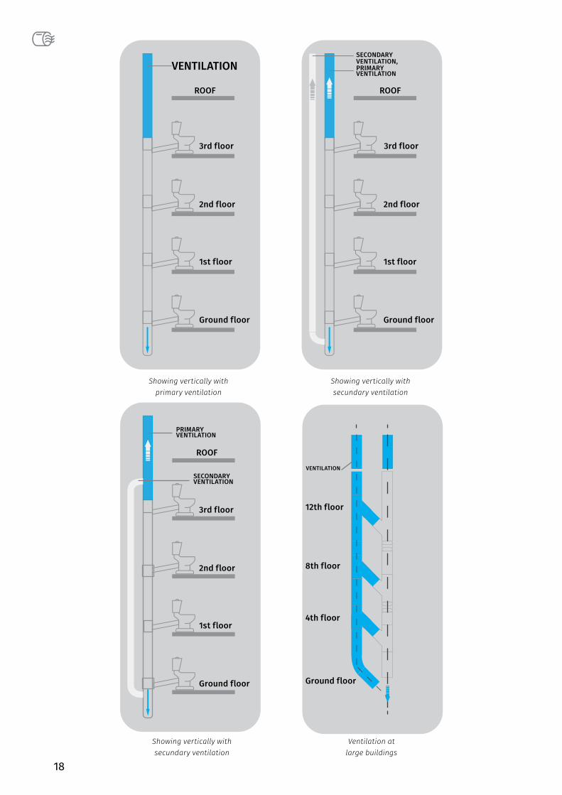
4.2 Pipes connectingElements of S LINE internal sewerage are connected by sockets and rubbers, which enables waterproof elements connection. Gluing pipes is not recommended. All pipes and fittings have at least one socket on the end. Peštan has also the pipes with 2 sockets on offer. Pipes without sockets can be connected by double sockets and sleeve sockets. Pipes can be cut by using a special blade for pipe or hand saw blades with fine teeth, as shown on the picture below.
Cutting pipes has to be done perpendicularly to pipe axis. The cut end of the pipe must be cleaned and skew. Skew of end of the pipe that was cut is achieved by fine sandpaper or a fine rasp. There are special tools for cutting, which during the cutting make a fine shape of the end of pipe. The table below shows the dimensions of the slope of pipe end.
Use all safety precautions!
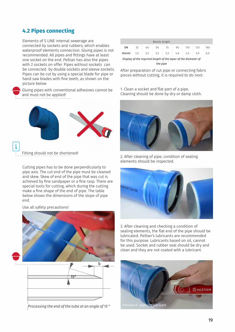
After preparation of cut pipe or connecting fabric pieces without cutting, it is required to do next:
1. Clean a socket and flat part of a pipe.Cleaning should be done by dry or damp cloth.
2. After cleaning of pipe, condition of sealingelements should be inspected.
3. After cleaning and checking a condition ofsealing elements, the flat end of the pipe should belubricated. Peštan’s lubricants are recommendedfor this purpose. Lubricants based on oil, cannotbe used. Socket and rubber seal should be dry andclean and they are not coated with a lubricant.
Preview of pipe ends cleaning
Processing the end of the tube at an angle of 15 °
Preview of muff with rubber
Preview of applying lubricant
15°
b
Gluing pipes with conventional adhesives cannot be and must not be applied!
Fitting should not be shortened!
Bevels length
DN 32 40 50 75 90 110 125 160
b(mm) 3,5 3,5 3,5 3,5 4,0 4,5 5,0 6,0
Display of the required length of the taper of the diameter of the pipe
20
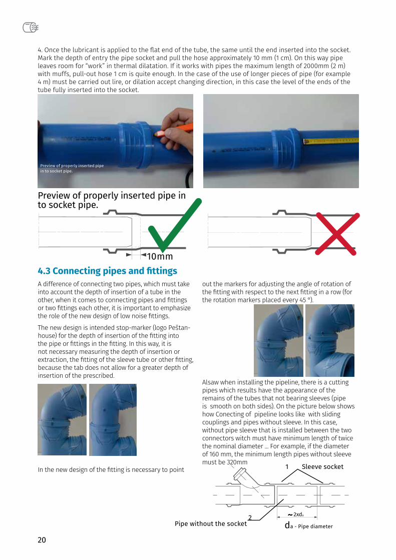
4. Once the lubricant is applied to the flat end of the tube, the same until the end inserted into the socket.Mark the depth of entry the pipe socket and pull the hose approximately 10 mm (1 cm). On this way pipeleaves room for “work” in thermal dilatation. If it works with pipes the maximum length of 2000mm (2 m)with muffs, pull-out hose 1 cm is quite enough. In the case of the use of longer pieces of pipe (for example4 m) must be carried out lire, or dilation accept changing direction, in this case the level of the ends of thetube fully inserted into the socket.
4.3 Connecting pipes and fittings
Preview of properly inserted pipe in to socket pipe.
Preview of properly inserted pipe in to socket pipe.
Sleeve socket
Pipe without the socket da - Pipe diameter
1
2
A difference of connecting two pipes, which must take into account the depth of insertion of a tube in the other, when it comes to connecting pipes and fittings or two fittings each other, it is important to emphasize the role of the new design of low noise fittings.
The new design is intended stop-marker (logo Peštan-house) for the depth of insertion of the fitting into the pipe or fittings in the fitting. In this way, it is not necessary measuring the depth of insertion or extraction, the fitting of the sleeve tube or other fitting, because the tab does not allow for a greater depth of insertion of the prescribed.
In the new design of the fitting is necessary to point
out the markers for adjusting the angle of rotation of the fitting with respect to the next fitting in a row (for the rotation markers placed every 45 °).
Alsaw when installing the pipeline, there is a cutting pipes which results have the appearance of the remains of the tubes that not bearing sleeves (pipe is smooth on both sides). On the picture below shows how Conecting of pipeline looks like with sliding couplings and pipes without sleeve. In this case, without pipe sleeve that is installed between the two connectors witch must have minimum length of twice the nominal diameter ... For example, if the diameter of 160 mm, the minimum length pipes without sleeve must be 320mm
21
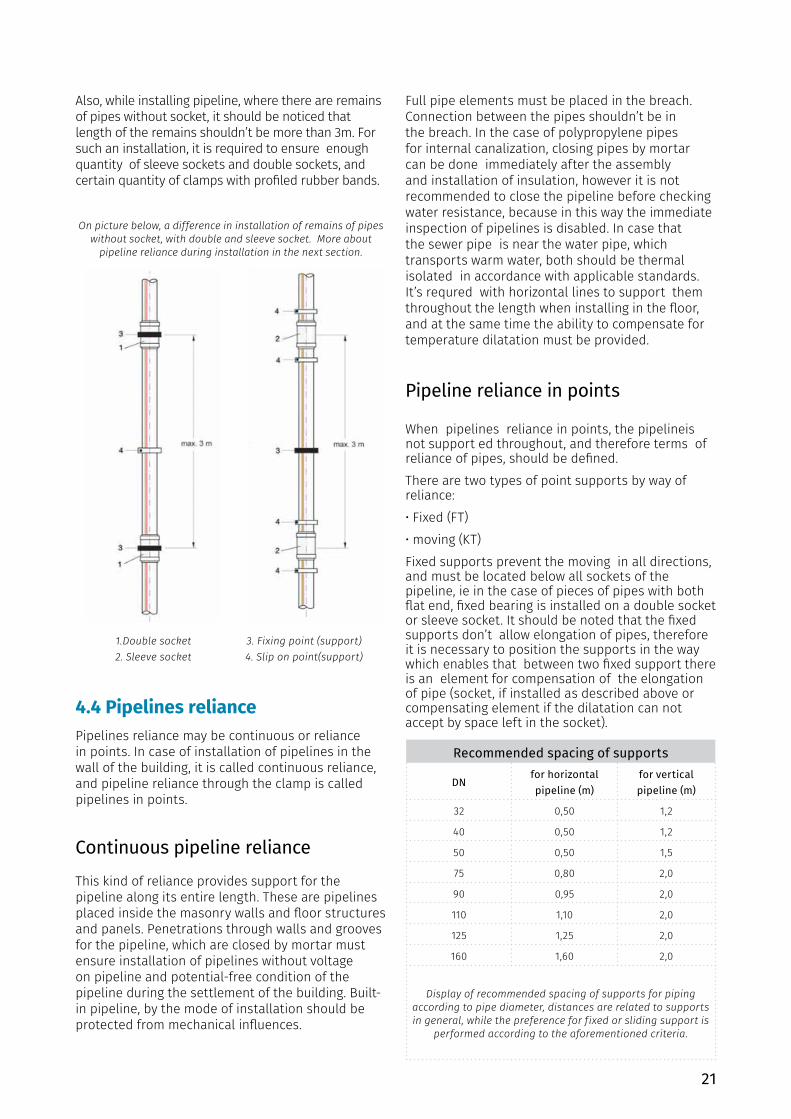
4.4 Pipelines reliancePipelines reliance may be continuous or reliance in points. In case of installation of pipelines in the wall of the building, it is called continuous reliance, and pipeline reliance through the clamp is called pipelines in points.
Continuous pipeline reliance This kind of reliance provides support for the pipeline along its entire length. These are pipelines placed inside the masonry walls and floor structures and panels. Penetrations through walls and grooves for the pipeline, which are closed by mortar must ensure installation of pipelines without voltage on pipeline and potential-free condition of the pipeline during the settlement of the building. Built-in pipeline, by the mode of installation should be protected from mechanical influences.
Full pipe elements must be placed in the breach. Connection between the pipes shouldn’t be in the breach. In the case of polypropylene pipes for internal canalization, closing pipes by mortar can be done immediately after the assembly and installation of insulation, however it is not recommended to close the pipeline before checking water resistance, because in this way the immediate inspection of pipelines is disabled. In case that the sewer pipe is near the water pipe, which transports warm water, both should be thermal isolated in accordance with applicable standards. It’s requred with horizontal lines to support them throughout the length when installing in the floor, and at the same time the ability to compensate for temperature dilatation must be provided.
Pipeline reliance in points
When pipelines reliance in points, the pipelineis not support ed throughout, and therefore terms of reliance of pipes, should be defined.There are two types of point supports by way of reliance:• Fixed (FT)• moving (KT)Fixed supports prevent the moving in all directions, and must be located below all sockets of the pipeline, ie in the case of pieces of pipes with both flat end, fixed bearing is installed on a double socket or sleeve socket. It should be noted that the fixed supports don’t allow elongation of pipes, therefore it is necessary to position the supports in the way which enables that between two fixed support there is an element for compensation of the elongation of pipe (socket, if installed as described above or compensating element if the dilatation can not accept by space left in the socket).
1.Double socket2. Sleeve socket
3. Fixing point (support)4. Slip on point(support)
Also, while installing pipeline, where there are remains of pipes without socket, it should be noticed that length of the remains shouldn’t be more than 3m. For such an installation, it is required to ensure enough quantity of sleeve sockets and double sockets, and certain quantity of clamps with profiled rubber bands.
On picture below, a difference in installation of remains of pipes without socket, with double and sleeve socket. More about
pipeline reliance during installation in the next section.
Recommended spacing of supports
DNfor horizontal pipeline (m)
for vertical pipeline (m)
32 0,50 1,2
40 0,50 1,2
50 0,50 1,5
75 0,80 2,0
90 0,95 2,0
110 1,10 2,0
125 1,25 2,0
160 1,60 2,0
Display of recommended spacing of supports for piping according to pipe diameter, distances are related to supports in general, while the preference for fixed or sliding support is
performed according to the aforementioned criteria.
22
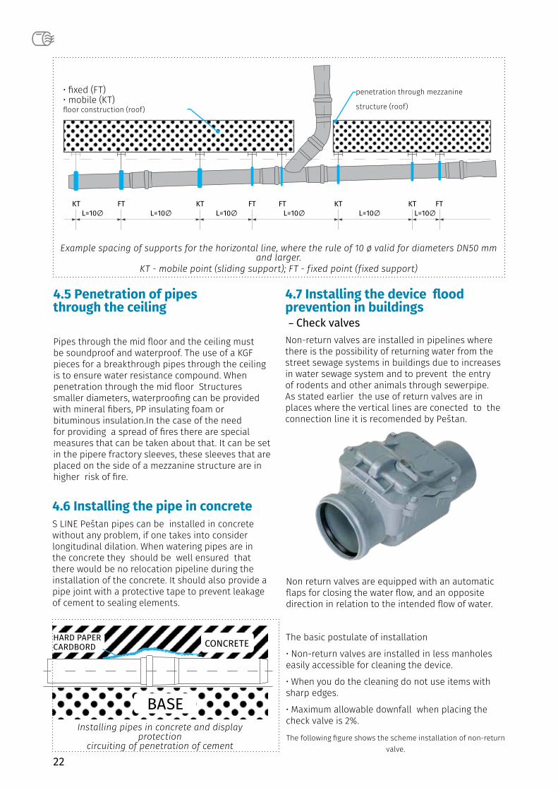
• fixed (FT)• mobile (KT)floor construction (roof)
penetration through mezzanine
structure (roof)
Example spacing of supports for the horizontal line, where the rule of 10 ø valid for diameters DN50 mm and larger.
KT - mobile point (sliding support); FT - fixed point (fixed support)
4.5 Penetration of pipes through the ceiling
Pipes through the mid floor and the ceiling must be soundproof and waterproof. The use of a KGF pieces for a breakthrough pipes through the ceiling is to ensure water resistance compound. When penetration through the mid floor Structures smaller diameters, waterproofing can be provided with mineral fibers, PP insulating foam or bituminous insulation.In the case of the need for providing a spread of fires there are special measures that can be taken about that. It can be set in the pipere fractory sleeves, these sleeves that are placed on the side of a mezzanine structure are in higher risk of fire.
4.6 Installing the pipe in concreteS LINE Peštan pipes can be installed in concrete without any problem, if one takes into consider longitudinal dilation. When watering pipes are in the concrete they should be well ensured that there would be no relocation pipeline during the installation of the concrete. It should also provide a pipe joint with a protective tape to prevent leakage of cement to sealing elements.
Installing pipes in concrete and display protection
circuiting of penetration of cement
4.7 Installing the device flood prevention in buildings – Check valves
Non-return valves are installed in pipelines where there is the possibility of returning water from the street sewage systems in buildings due to increases in water sewage system and to prevent the entry of rodents and other animals through sewerpipe. As stated earlier the use of return valves are in places where the vertical lines are conected to the connection line it is recomended by Peštan.
Non return valves are equipped with an automatic flaps for closing the water flow, and an opposite direction in relation to the intended flow of water.
The basic postulate of installation
• Non-return valves are installed in less manholeseasily accessible for cleaning the device.
• When you do the cleaning do not use items withsharp edges.
• Maximum allowable downfall when placing thecheck valve is 2%.
The following figure shows the scheme installation of non-return valve.
CONCRETEHARD PAPERCARDBORD
BASE
23
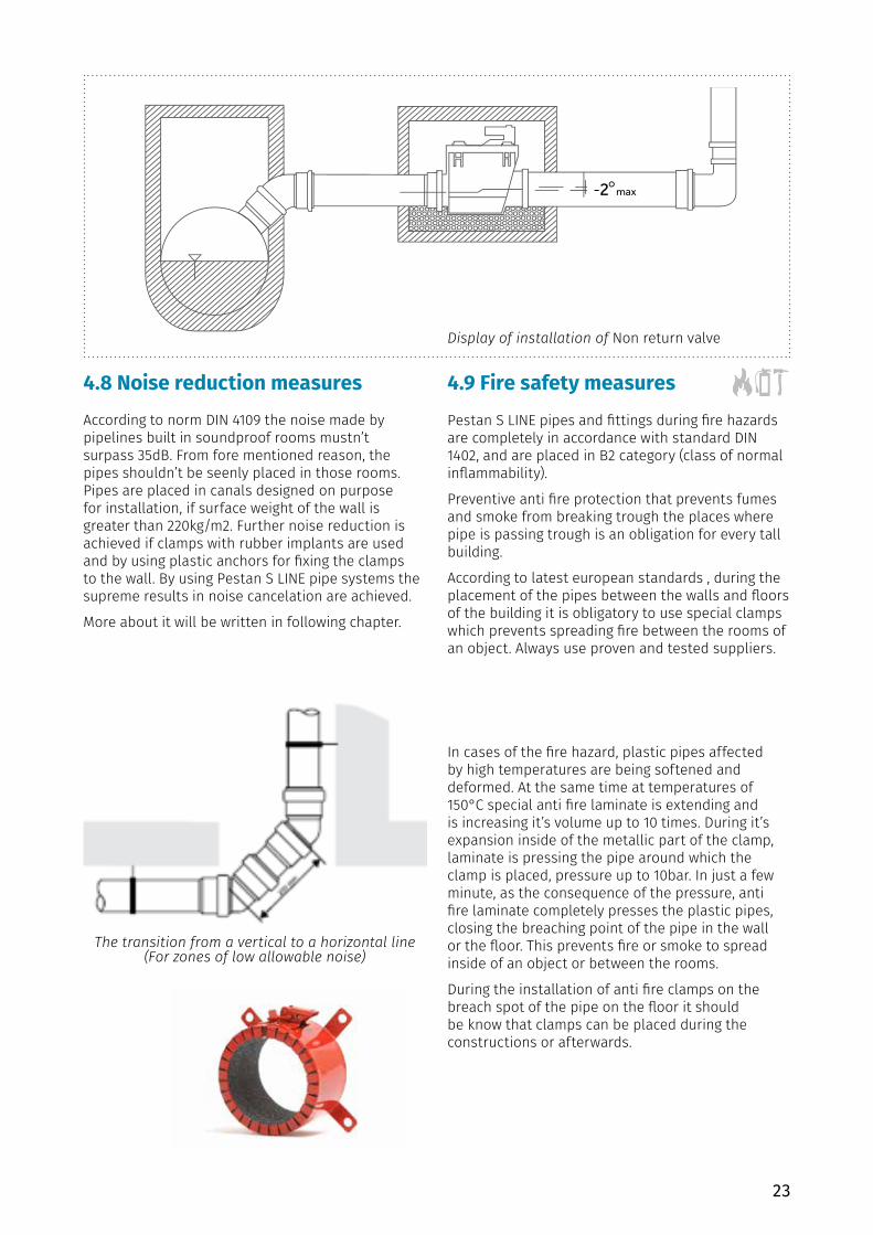
4.8 Noise reduction measures According to norm DIN 4109 the noise made by pipelines built in soundproof rooms mustn’t surpass 35dB. From fore mentioned reason, the pipes shouldn’t be seenly placed in those rooms. Pipes are placed in canals designed on purpose for installation, if surface weight of the wall is greater than 220kg/m2. Further noise reduction is achieved if clamps with rubber implants are used and by using plastic anchors for fixing the clamps to the wall. By using Pestan S LINE pipe systems the supreme results in noise cancelation are achieved.
More about it will be written in following chapter.
The transition from a vertical to a horizontal line (For zones of low allowable noise)
Display of installation of Non return valve
4.9 Fire safety measuresPestan S LINE pipes and fittings during fire hazards are completely in accordance with standard DIN 1402, and are placed in B2 category (class of normal inflammability).
Preventive anti fire protection that prevents fumes and smoke from breaking trough the places where pipe is passing trough is an obligation for every tall building.
According to latest european standards , during the placement of the pipes between the walls and floors of the building it is obligatory to use special clamps which prevents spreading fire between the rooms of an object. Always use proven and tested suppliers.
In cases of the fire hazard, plastic pipes affected by high temperatures are being softened and deformed. At the same time at temperatures of 150°C special anti fire laminate is extending and is increasing it’s volume up to 10 times. During it’s expansion inside of the metallic part of the clamp, laminate is pressing the pipe around which the clamp is placed, pressure up to 10bar. In just a few minute, as the consequence of the pressure, anti fire laminate completely presses the plastic pipes, closing the breaching point of the pipe in the wall or the floor. This prevents fire or smoke to spread inside of an object or between the rooms.
During the installation of anti fire clamps on the breach spot of the pipe on the floor it should be know that clamps can be placed during the constructions or afterwards.
24
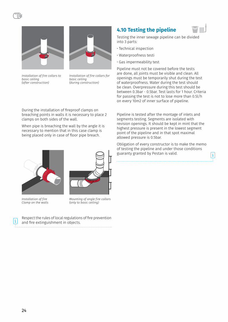
Installation of fire collars for basic ceiling(during construction)
Installation of fire collars to basic ceiling (after construction)
Installation of fireClamp on the walls
Mounting of angle fire collars (only to basic ceiling)
4.10 Testing the pipeline Testing the inner sewage pipeline can be divided into 3 parts:
• Technical inspection
• Waterproofness testi
• Gas impermeability test
Pipeline must not be covered before the tests are done, all joints must be visible and clean. All openings must be temporarily shut during the test of waterproofness. Water during the test should be clean. Overpressure during this test should be between 0.3bar - 0.5bar. Test lasts for 1 hour. Criteria for passing the test is not to lose more than 0.5l/h on every 10m2 of inner surface of pipeline.
Pipeline is tested after the montage of inlets and segments testing. Segments are isolated with revision openings. It should be kept in mint that the highest pressure is present in the lowest segment point of the pipeline and in that spot maximal allowed pressure is 0.5bar.
Obligation of every constructor is to make the memo of testing the pipeline and under those conditions guaranty granted by Pestan is valid.
During the installation of fireproof clamps on breaching points in walls it is necessary to place 2 clamps on both sides of the wall.
When pipe is breaching the wall by the angle it is necessary to mention that in this case clamp is being placed only in case of floor pipe breach.
Respect the rules of local regulations of fire prevention and fire extinguishment in objects.
25
NOISE REDUCTIONUse of the pipeline
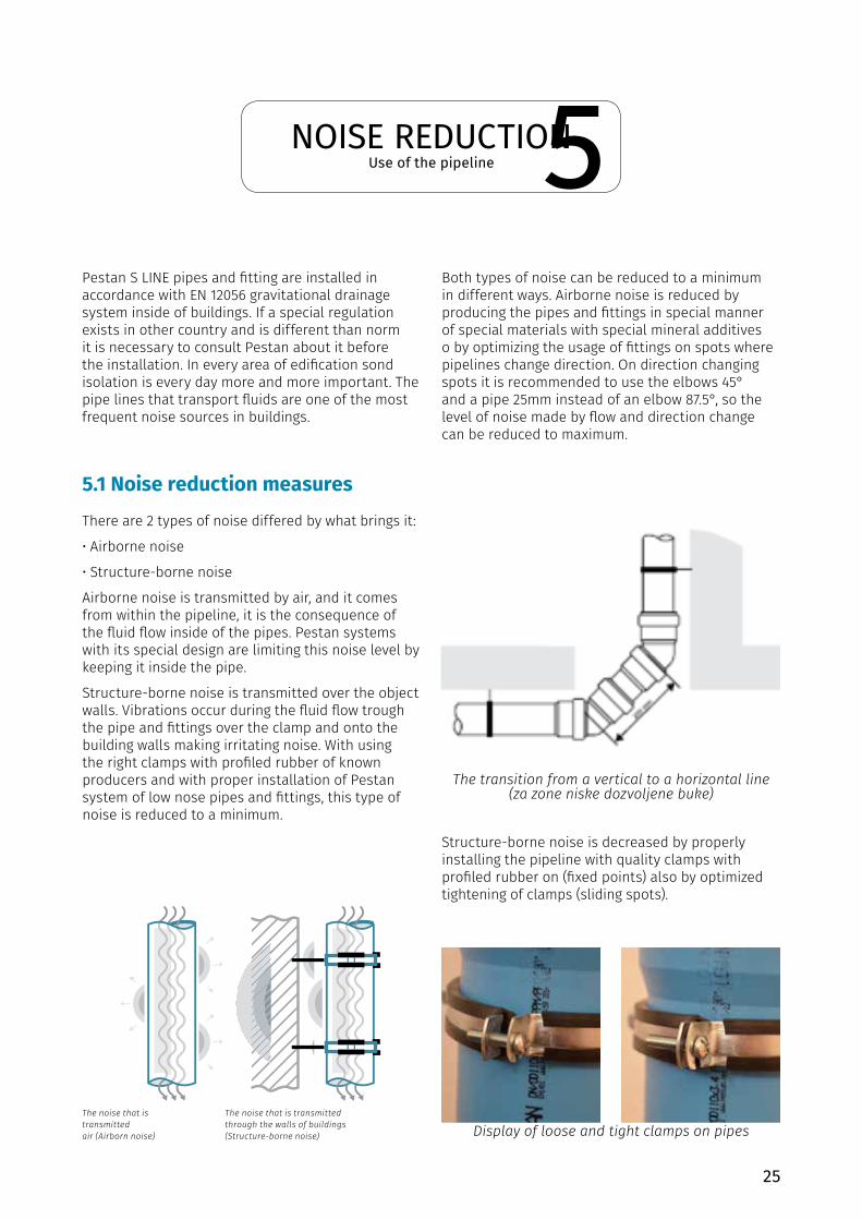
Pestan S LINE pipes and fitting are installed in accordance with EN 12056 gravitational drainage system inside of buildings. If a special regulation exists in other country and is different than norm it is necessary to consult Pestan about it before the installation. In every area of edification sond isolation is every day more and more important. The pipe lines that transport fluids are one of the most frequent noise sources in buildings.
Both types of noise can be reduced to a minimum in different ways. Airborne noise is reduced by producing the pipes and fittings in special manner of special materials with special mineral additives o by optimizing the usage of fittings on spots where pipelines change direction. On direction changing spots it is recommended to use the elbows 45°and a pipe 25mm instead of an elbow 87.5°, so the level of noise made by flow and direction change can be reduced to maximum.
Structure-borne noise is decreased by properly installing the pipeline with quality clamps with profiled rubber on (fixed points) also by optimized tightening of clamps (sliding spots).
5.1 Noise reduction measures There are 2 types of noise differed by what brings it:
• Airborne noise
• Structure-borne noise
Airborne noise is transmitted by air, and it comes from within the pipeline, it is the consequence of the fluid flow inside of the pipes. Pestan systems with its special design are limiting this noise level by keeping it inside the pipe.
Structure-borne noise is transmitted over the object walls. Vibrations occur during the fluid flow trough the pipe and fittings over the clamp and onto the building walls making irritating noise. With using the right clamps with profiled rubber of known producers and with proper installation of Pestan system of low nose pipes and fittings, this type of noise is reduced to a minimum.
The transition from a vertical to a horizontal line (za zone niske dozvoljene buke)
Display of loose and tight clamps on pipesThe noise that is transmittedair (Airborn noise)
The noise that is transmitted through the walls of buildings (Structure-borne noise)
5
26
5.2 Lab testing of sound isolation
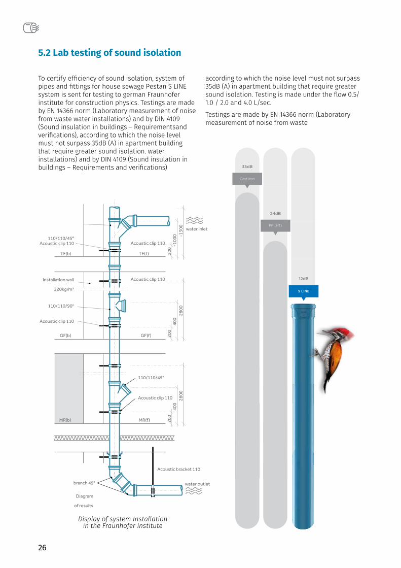
To certify efficiency of sound isolation, system of pipes and fittings for house sewage Pestan S LINE system is sent for testing to german Fraunhofer institute for construction physics. Testings are made by EN 14366 norm (Laboratory measurement of noise from waste water installations) and by DIN 4109 (Sound insulation in buildings – Requirementsand verifications), according to which the noise level must not surpass 35dB (A) in apartment building that require greater sound isolation. water installations) and by DIN 4109 (Sound insulation in buildings – Requirements and verifications)
according to which the noise level must not surpass 35dB (A) in apartment building that require greater sound isolation. Testing is made under the flow 0.5/ 1.0 / 2.0 and 4.0 L/sec.
Testings are made by EN 14366 norm (Laboratory measurement of noise from waste
Display of system Installationin the Fraunhofer Institute
Acoustic clip 110110/110/45°
110/110/90°
Installation wall
220kg/m²
Acoustic clip 110
branch 45°
110/110/45°
Acoustic clip 110
Acoustic clip 110
Acoustic clip 110
water inlet
water outlet
Acoustic bracket 110
MR(b)
GF(b) GF(f)
MR(f)
TF(b) TF(f)
200
400
2800
200
400
2800
Diagram
of results
MR(b)
200
-100
0 -130
0
26-9 page
S LINE
12dB
PP (HT)
24dB
Cast iron
35dB
27
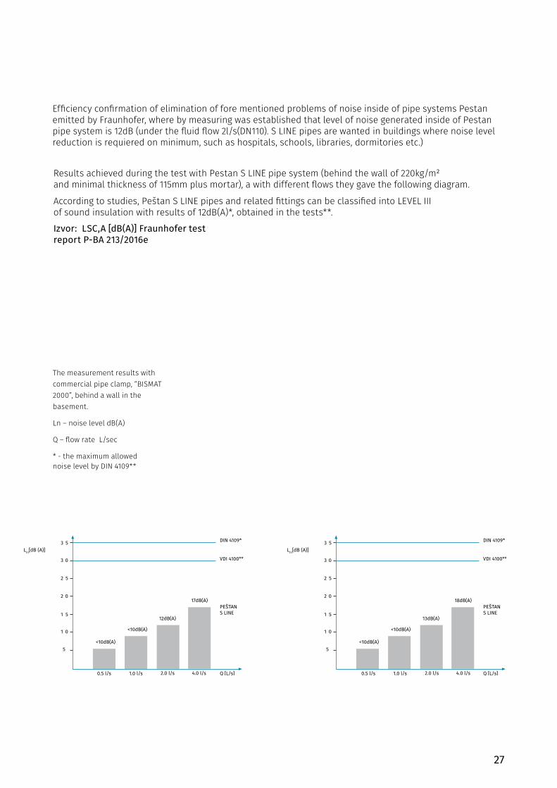
The measurement results with commercial pipe clamp, “BISMAT 2000”, behind a wall in the basement.
Ln – noise level dB(A)
Q – flow rate L/sec
* - the maximum allowednoise level by DIN 4109**
Izvor: LSC,A [dB(A)] Fraunhofer test report P-BA 213/2016e
Results achieved during the test with Pestan S LINE pipe system (behind the wall of 220kg/m² and minimal thickness of 115mm plus mortar), a with different flows they gave the following diagram.
According to studies, Peštan S LINE pipes and related fittings can be classified into LEVEL III of sound insulation with results of 12dB(A)*, obtained in the tests**.
Efficiency confirmation of elimination of fore mentioned problems of noise inside of pipe systems Pestan emitted by Fraunhofer, where by measuring was established that level of noise generated inside of Pestan pipe system is 12dB (under the fluid flow 2l/s(DN110). S LINE pipes are wanted in buildings where noise level reduction is requiered on minimum, such as hospitals, schools, libraries, dormitories etc.)

28
5.3 Level of sound isolation and calssification
90
Nivo I zvučne izolacije – zahtevi prema DIN 4109 korespondiraju sa 30 dB(A)
Nivo II zvučne izolacije – viši nivo zvučne izolacije korespondira sa 25 dB(A)
Nivo III zvučne izolacije – najviši nivo zvučne izolacije korespondira sa 20 dB(A)
Nivo I zvučne izolacije – porodične kuće
Nivo II zvučne izolacije – apartmanske zgrade, stambene i poslovne zgrade manje spratnosti
Nivo III zvučne izolacije – hoteli, bolnice, biblioteke, čitaonice, stambeni kompleksi
•
•
•
•
•
•
Prema VDI 4100, postoji tri stepena zvučne izolacije, u zavisnosti od namene objekta u kome su cevi instalirane:
VDI nivoi zvučne izolacije i klasifikacija:
On family houses
Sound insulation level I or on agreement
Apartment bulidings, residential and office buildings, comfort apartments
Sound insulation level II or higher
Hotels, hospitals, residential complexes
Sound insulation level III enhanced agreements
According to VDI 4100 there are 3 degrees in sound isolation, depending on the purpose of object in which the pipes are installed:
*Level 1 DIN 4109 corresponds to 30dB (A)
*Level 2 corresponds to 25dB (A)
*Level 3 corresponds to 20 dB (A)
VDI level of sound isolation and class
*Level 1 - Family house
*Level 2 - apartment building and offices
*Leve 3 - Hotels, hospitals, libraries, living complexes
Family house Apartment building and offices
Hotels, hospitals, libraries, living complexes
Level I of sound isolation Level II of sound isolation
Level III of sound isolation
29
MAINTENANCE
INTERFERENCEtrouble shooting
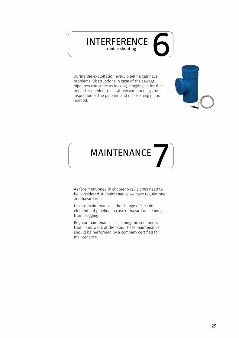
As fore mentioned in chapter 6 revisiones need to be considered. In maintenance we have regular one and hazard one.
Hazard maintenance is the change of certain elements of pipeline in case of hazard or cleaning from clogging.
Regular maintenance is cleaning the sediments from inner walls of the pipe. These maintenance should be performed by a company certified for maintenance.
During the exploitation every pipeline can have problems. Obstructions in case of the sewage pipelines can come as leaking, clogging so for that need it is needed to instal revision openings for inspection of the pipeline and it’s cleaning if it is needed.
6
7
30
POST-USAGEPROCEDURE IN POST-USAGE
DISMANTLING DISMANTLE AND REMOVAL
Dismantling and removing the pipeline is done in following manner:• Drain out the water• In case the pipes are in the walls, walls are need to be breached and pipe removed from the wall.• Detach the joints• If needed cut short the parts for easier manipulation• Removed parts put on transport vehicle and drive of to place predicted to put away plastic masses so it could be recycled
PP
As fore mentioned PP mass for S LINE system can be recycled. By recycling S LINE does not lose it’s physical/chemical abilities, so it can be used for various different purposes afterwards.
Pestan is using exclusively compound of high quality only from world know producers.
Plastic masses are bing soted out by code of material so the code for S lINE is:
8
9
31
ABREVIATIONS LIST OF ABREVIATIONS
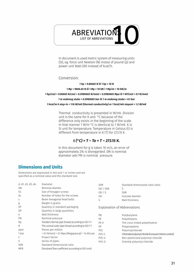
In document is used metric system of measuring units (SI), eg. force unit Newton (N) instea of pound (p) and power unit Watt (W) instead of kcal/h.
Conversion:
Thermal conductivity is presented in W/mk. Division unit is the same for K and °C because of the difference only exists in the beginning of the scale. In that manner 1 W/m °C is identical to 1 W/mK. K is SI unit for temperature. Temperature in Celsius (t) is different from temperature in K (T) for 273.15 K.
In this document for g is taken 10 m/s, an error of approximately 2% is disregarded. DN is nominal diameter adn PN is nominal pressure.
1 kp = 9.80665 N ili 1 kp ≈ 10 N
1 Mp = 9806.65 N ili 1 Mp ≈ 10 kN i 1 Mp/m = 10 kN/m
1 kp/cm2 = 9.80665 N/cm2 = 0.0980665 N/mm2 = 0.0980665 Mpa ili 1 kP/cm2 ≈ 0.1 N/mm2
1 m vodenog stubs = 0.0980665 bar ili 1 m vodenog stuba ≈ 0.1 bar
1 kcal/m h step-in = 1.16 W/mK (thermal conductivity) or 1 kcal/mh stepeni ≈ 1.2 W/mK
t (°C) = T – To = T – 273.15 K.
Dimensions and UnitsDimensions are expressed in mm and / or inches and are specified as a nominal value and the standard size.
d, d1, d2, d3, d4 DiameterDN Nominal diamterSC Size of hexagon screwsAL Number of holes for the screwss Beam hexagonal head boltsg Weight in gramsSP Quantity in standard packagingGP Quantity in large quantitiese Wall thicknessPN Nominal pressureRp Parallel internal pipe thread according to ISO 7-1R The conical outer pipe thread according to ISO 7-1ppm Pieces per million1 bar = 0.1 N/mm2 = 0.1 Mpa (Megapascal) = 14.504 psiC Project factorS Series of pipesSDR Standard dimensional ratioMFR Dissolved flow coefficient according to ISO 4440
SDR Standard dimensional ratio ratio:OD / SDR SOD / S SDROD Outside diamterS Wall thickness
Explanation of Abbreviations
PB PolybutylenePE PolyethylenePE-X The cross-linked polyethylenePP PolypropylenePVC PolyvinylchloridePVC-C Chlorinated polyvinyl chloride (increased chlorine content)PVC-U Non-plasticised polyvinyl chloridePVC-O Oriental polyvinyl chloride
10
32
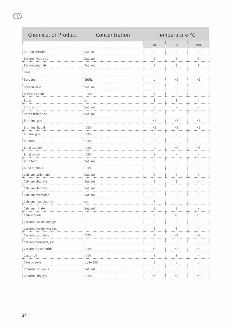
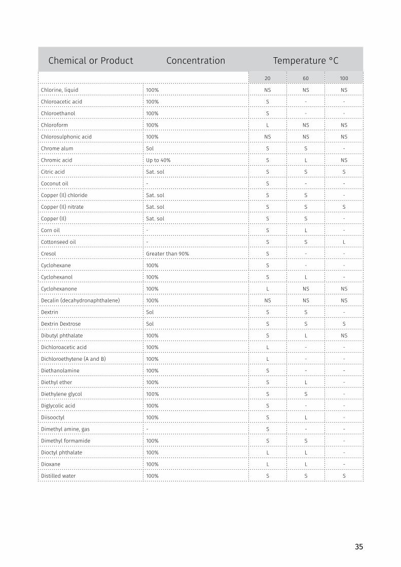
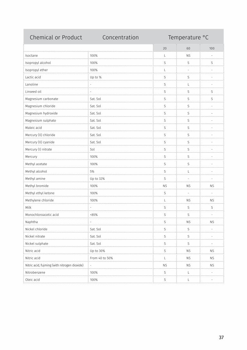
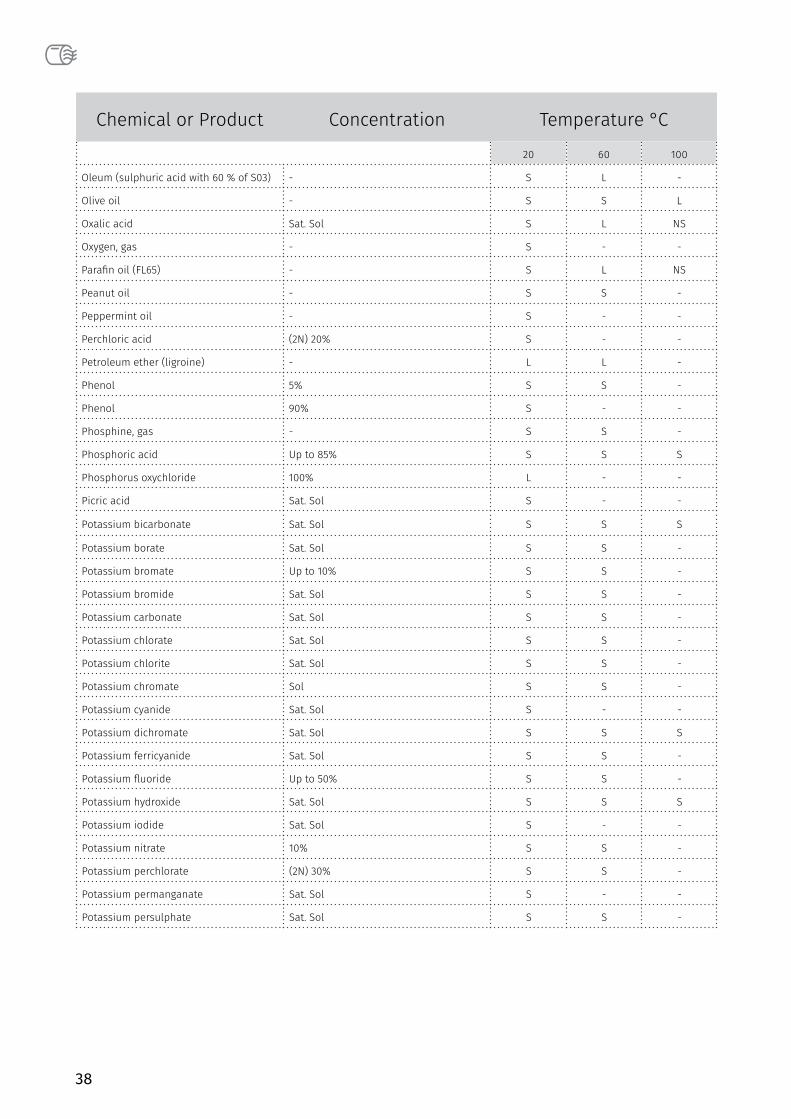
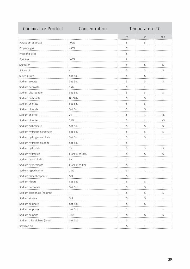
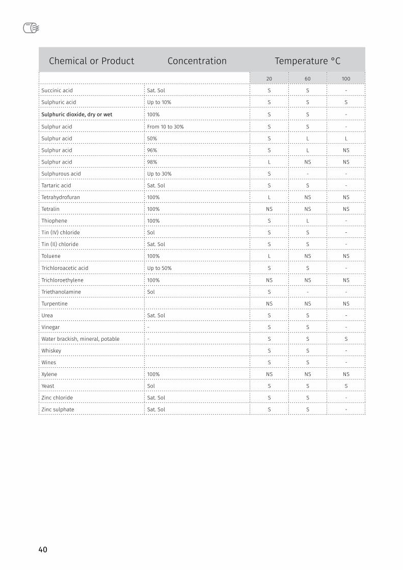
CHEMICAL RESISTANCETABLE OF TABLE OF CHEMICAL RESISTANCE
11.1 Introduction
Table in this document sums up data of PP chemical resistance, it is used in multiple countries, made as a result f practical experience and test results.
Izvor : ISO/TR 10358
Table contains evaluation of chemical resistance of big number of fluids estimated as aggressive or inert towards PP. Estimation is based upon values gained from tests where the sample of PP is submerged in fluid sample in temperatures 20, 60 i 100°C and atmosphere pressure, following the characteristics of tension rigidity under some conditions.
Classification will be estimated while taking in account limited number of fluids considering technically or commercially more important by using the equipment that enables testing under pressure and estimation of coefficient of chemical resistance separately for each fluid. In this way the tests will give complete information about use of PP pipes for transport of mentioned fluids including their use under pressure.
11.2 Field of application
This document contains classification of chemical resistance of PP for about 180 fluids. It is meant to supply with general guidelines about possibilities of use PP pipes for fluid transfer>
In temperatures 20, 60 and 100°C
In absence of inner pressure and outer mechanical tension (bending, distortion for eg.)
11.3 Definition and symbols as abbreviations
Critaria of classification, symbols and abbreviations used in this chapter are following:
S – satisfactory L – partially
Chemical resistance of PP exposed to activity of fluids is classified as partially satisfying when the results from around different countries came in.
Also this classification (L) is used for resistance to activity of chemical fluids at which depending on the parameters can be used both S and NS
NS – unsatisfactory
Chemical resisance of PP exposed to activity of fluids is put to NS category when test results from all different countries that participated came in.
In NS category are materials which depending on the parameters have mark NS or L.
Saturated solution - saturated aqueous solution prepared
at 20 ° C
Solution - A unsaturated aqueous solution
concentrations higher than 10%
Diluted solution - diluted aqueous solution in
concentrations equal to or lower than 10%
A working solution - aqueous solution with the usual
concentration for industrial use
Solution concentration recorded in the text are
expressed in percentages by weight. Aqueous solutions of
poorly soluble chemicals , regarding chemical activity towards polypropylene, are considered saturated solutions. Overall, in this catalog are used common chemical names.
This table is made as a guide for polypropylene users. In case that a chemical compound is not in the table, or due to uncertainties related to the
chemical resistance in an application, please contact Peštan for advice and testing proposal.
11
33
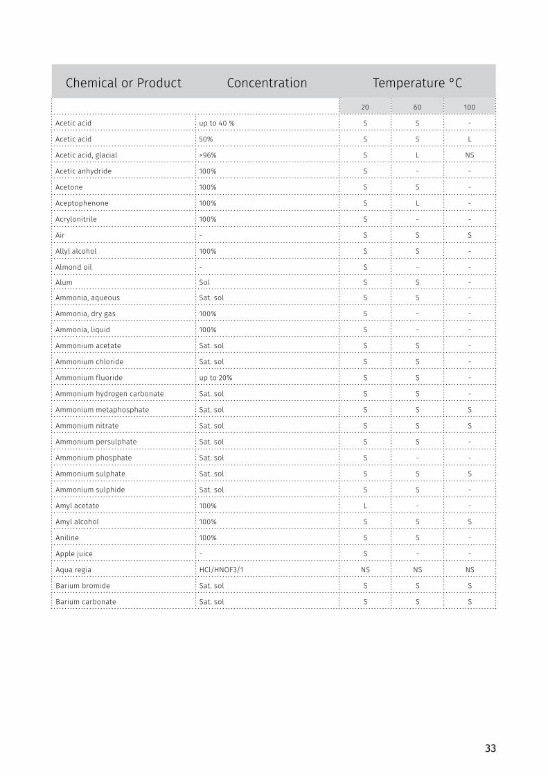
Chemical or Product Concentration Temperature °C
20 60 100
Acetic acid up to 40 % S S -
Acetic acid 50% S S L
Acetic acid, glacial >96% S L NS
Acetic anhydride 100% S - -
Acetone 100% S S -
Aceptophenone 100% S L -
Acrylonitrile 100% S - -
Air - S S S
Allyl alcohol 100% S S -
Almond oil - S - -
Alum Sol S S -
Ammonia, aqueous Sat. sol S S -
Ammonia, dry gas 100% S - -
Ammonia, liquid 100% S - -
Ammonium acetate Sat. sol S S -
Ammonium chloride Sat. sol S S -
Ammonium fluoride up to 20% S S -
Ammonium hydrogen carbonate Sat. sol S S -
Ammonium metaphosphate Sat. sol S S S
Ammonium nitrate Sat. sol S S S
Ammonium persulphate Sat. sol S S -
Ammonium phosphate Sat. sol S - -
Ammonium sulphate Sat. sol S S S
Ammonium sulphide Sat. sol S S -
Amyl acetate 100% L - -
Amyl alcohol 100% S S S
Aniline 100% S S -
Apple juice - S - -
Aqua regia HCl/HNOF3/1 NS NS NS
Barium bromide Sat. sol S S S
Barium carbonate Sat. sol S S S
34
Chemical or Product Concentration Temperature °C
20 60 100
Barium chloride Sat. sol S S S
Barium hydroxide Sat. sol S S S
Barium sulphide Sat. sol S S S
Beer - S S -
Benzene 100% L NS NS
Benzoic acid Sat. sol S S -
Benzyl alcohol 100% S L -
Borax sol S S -
Boric acid Sat. sol S - -
Boron trifluoride Sat. sol S - -
Bormine, gas - NS NS NS
Bromine, liquid 100% NS NS NS
Butane, gas 100% S - -
Butanol 100% S L L
Butyl acetate 100% L NS NS
Butyl glycol 100% S - -
Butil fenol Sat. sol S - -
Butyl phenols 100% S L L
Calcium carbonate Sat. sol S S S
Calcium chlorate Sat. sol S S -
Calcium chlorate Sat. sol S S S
Calcium hydroxide Sat. sol S S S
Calcium hypochlorite sol S - -
Calcium nitrate Sat. sol S S -
Camphor oil - NS NS NS
Carbon dioxide, dry gas - S S -
Carbon dioxide, wet gas - S S -
Carbon disulphide 100% S NS NS
Carbon monoxide, gas - S S -
Carbon tetrachloride 100% NS NS NS
Castor oil 100% S S -
Caustic soda Up to 50% S L L
Chlorine, aqueous Sat. sol S L -
Chlorine, dry gas 100% NS NS NS
35
Chemical or Product Concentration Temperature °C
20 60 100
Chlorine, liquid 100% NS NS NS
Chloroacetic acid 100% S - -
Chloroethanol 100% S - -
Chloroform 100% L NS NS
Chlorosulphonic acid 100% NS NS NS
Chrome alum Sol S S -
Chromic acid Up to 40% S L NS
Citric acid Sat. sol S S S
Coconut oil - S - -
Copper (Il) chloride Sat. sol S S -
Copper (Il) nitrate Sat. sol S S S
Copper (Il) Sat. sol S S -
Corn oil - S L -
Cottonseed oil - S S L
Cresol Greater than 90% S - -
Cyclohexane 100% S - -
Cyclohexanol 100% S L -
Cyclohexanone 100% L NS NS
Decalin (decahydronaphthalene) 100% NS NS NS
Dextrin Sol S S -
Dextrin Dextrose Sol S S S
Dibutyl phthalate 100% S L NS
Dichloroacetic acid 100% L - -
Dichloroethytene (A and B) 100% L - -
Diethanolamine 100% S - -
Diethyl ether 100% S L -
Diethylene glycol 100% S S -
Diglycolic acid 100% S - -
Diisooctyl 100% S L -
Dimethyl amine, gas - S - -
Dimethyl formamide 100% S S -
Dioctyl phthalate 100% L L -
Dioxane 100% L L -
Distilled water 100% S S S

36
Chemical or Product Concentration Temperature °C
20 60 100
Ethyl alcohol Up to 95% S S S
Ethyl chloride, gas - NS NS NS
Ethylene chloride (mono and di) - L L -
Ethyl ether 100% S L -
Ethylene glycol 100% S S S
Ethanolamine 100% S - -
Ethyl acetate 100% L NS NS
Ferric chloride Sat. sol S S S
Ferric chloride Formaldehyde 40% S - -
Formic acid 10% S S L
Formic acid 85% S NS NS
Formic acid, anhydrous 100% S L L
Fructose Sol S S S
Fruit juice - S S S
Gasoline. petrol (aliphatic hydrocarbons) - NS NS NS
Gelatine - S S -
Glucose 20% S S S
Glycerine 100% S S S
Glycolic acid 30% S - -
Heptane 100% L NS NS
Hexane 100% S L -
Hydrobromic acid More than 48% S L NS
Hydrochloric acid More than 20% S S S
Hydrochloric acid 30% S L L
Hydrochloric acid From 35 to 36% S - -
Hydrofluoric acid Dil.sol S - -
Hydrofluoric acid 40% S - -
Hydrogen 100% S - -
Hydrogen chloride, dry gas 100% S S -
Hydrogen peroxide Up to 10% S - -
Hydrogen peroxide Up to 30% S L -
Hydrogen sulphide, dry gas 100% S S -
Iodine, in alcohol - S - -
37
Chemical or Product Concentration Temperature °C
20 60 100
Isoctane 100% L NS -
Isopropyl alcohol 100% S S S
Isopropyl ether 100% L - -
Lactic acid Up to % S S -
Lanoline - S L -
Linseed oil - S S S
Magnesium carbonate Sat. Sol S S S
Magnesium chloride Sat. Sol S S -
Magnesium hydroxide Sat. Sol S S -
Magnesium sulphate Sat. Sol S S -
Maleic acid Sat. Sol S S -
Mercury (Il) chloride Sat. Sol S S -
Mercury (Il) cyanide Sat. Sol S S -
Mercury (I) nitrate Sol S S -
Mercury 100% S S -
Methyl acetate 100% S S -
Methyl alcohol 5% S L -
Methyl amine Up to 32% S - -
Methyl bromide 100% NS NS NS
Methyl ethyl ketone 100% S - -
Methylene chloride 100% L NS NS
Milk - S S S
Monochloroacetic acid <85% S S -
Naphtha - S NS NS
Nickel chloride Sat. Sol S S -
Nickel nitrate Sat. Sol S S -
Nickel sulphate Sat. Sol S S -
Nitric acid Up to 30% S NS NS
Nitric acid From 40 to 50% L NS NS
Nitric acid, fujming (with nitrogen dioxide) - NS NS NS
Nitrobenzene 100% S L -
Oleic acid 100% S L -
38
Chemical or Product Concentration Temperature °C
20 60 100
Oleum (sulphuric acid with 60 % of S03) - S L -
Olive oil - S S L
Oxalic acid Sat. Sol S L NS
Oxygen, gas - S - -
Parafin oil (FL65) - S L NS
Peanut oil - S S -
Peppermint oil - S - -
Perchloric acid (2N) 20% S - -
Petroleum ether (ligroine) - L L -
Phenol 5% S S -
Phenol 90% S - -
Phosphine, gas - S S -
Phosphoric acid Up to 85% S S S
Phosphorus oxychloride 100% L - -
Picric acid Sat. Sol S - -
Potassium bicarbonate Sat. Sol S S S
Potassium borate Sat. Sol S S -
Potassium bromate Up to 10% S S -
Potassium bromide Sat. Sol S S -
Potassium carbonate Sat. Sol S S -
Potassium chlorate Sat. Sol S S -
Potassium chlorite Sat. Sol S S -
Potassium chromate Sol S S -
Potassium cyanide Sat. Sol S - -
Potassium dichromate Sat. Sol S S S
Potassium ferricyanide Sat. Sol S S -
Potassium fluoride Up to 50% S S -
Potassium hydroxide Sat. Sol S S S
Potassium iodide Sat. Sol S - -
Potassium nitrate 10% S S -
Potassium perchlorate (2N) 30% S S -
Potassium permanganate Sat. Sol S - -
Potassium persulphate Sat. Sol S S -
39
Chemical or Product Concentration Temperature °C
20 60 100
Potassium sulphate 100% S S -
Propane, gas <50% S - -
Propionic acid - S - -
Pyridine 100% L - -
Seawater - S S S
Silicon oil - S S S
Silver nitrate Sat. Sol S S L
Sodium acetate Sat. Sol S S S
Sodium benzoate 35% S L -
Sodium bicarbonate Sat. Sol S S S
Sodium carbonate Do 50% S S L
Sodium chlorate Sat. Sol S S -
Sodium chloride Sat. Sol S S -
Sodium chlorite 2% S L NS
Sodium chlorite 20% S L NS
Sodium dichromate Sat. Sol S S S
Sodium hydrogen carbonate Sat. Sol S S S
Sodium hydrogen sulphate Sat. Sol S S -
Sodium hydrogen sulphite Sat. Sol S - -
Sodium hydroxide 1% S S S
Sodium hydroxide From 10 to 60% S S S
Sodium hypochlorite 5% S S -
Sodium hypochlorite From 10 to 15% S - -
Sodium hypochlorite 20% S L -
Sodium metaphosphate Sol S - -
Sodium nitrate Sat. Sol S S -
Sodium perborate Sat. Sol S S -
Sodium phosphate (neutral) - S S S
Sodium silicate Sol S S -
Sodium sulphate Sat. Sol S S -
Sodium sulphate Sat. Sol S - -
Sodium sulphite 40% S S S
Sodium thiosulphate (hypo) Sat. Sol S - -
Soybean oil - S L -
40
Chemical or Product Concentration Temperature °C
20 60 100
Succinic acid Sat. Sol S S -
Sulphuric acid Up to 10% S S S
Sulphuric dioxide, dry or wet 100% S S -
Sulphur acid From 10 to 30% S S -
Sulphur acid 50% S L L
Sulphur acid 96% S L NS
Sulphur acid 98% L NS NS
Sulphurous acid Up to 30% S - -
Tartaric acid Sat. Sol S S -
Tetrahydrofuran 100% L NS NS
Tetralin 100% NS NS NS
Thiophene 100% S L -
Tin (IV) chloride Sol S S -
Tin (Il) chloride Sat. Sol S S -
Toluene 100% L NS NS
Trichloroacetic acid Up to 50% S S -
Trichloroethylene 100% NS NS NS
Triethanolamine Sol S - -
Turpentine NS NS NS
Urea Sat. Sol S S -
Vinegar - S S -
Water brackish, mineral, potable - S S S
Whiskey S S -
Wines S S -
Xylene 100% NS NS NS
Yeast Sol S S S
Zinc chloride Sat. Sol S S -
Zinc sulphate Sat. Sol S S -
41
CERTIFICATES
The information contained in this catalog to our the information is accurate and reliable as of the day of publication. Peštan does not provide a guarantee and gives no explanation for accuracy or completeness of the information contained here, and assumes no liability in connection with the consequences of their use or for any misprint. Our products are intended for general consumption. The responsibility of the buyer is to inspect and test our products in order to ascertain the suitability of the product for customer’s particular purpose. The buyer is also responsible for appropriate, safe and legal use, processing and handling our product. Here, nothing provides a guarantee. There is no liability that can be accepted and refers to the use of Peštan products in conjunction with other
materials. The information contained in this catalog refers exclusively to our products when not used in conjunction with any third party.
Peštan points out that data on the chemical resistance of Polypropylene displayed in the list of chemical resistance in this catalog are based on data collected from several sources. Peštan does not guarantee the correctness and accuracy such data and accepts no liability of any loss or damage as a result of use, inability to use or the result of using catalog by the customer or any third party to whom such data can be transmitted. You are obliged to enable suitable test to ensure convenience and safety products for the intended use in accordance with applicable regulations.
Disclaimer
IGH Hrvatska Fraunhofer Nemačka IMS Srbija
12
42
PRODUCTION PROGRAMS LINE pipes & fittings od Ø32 do Ø16013
43
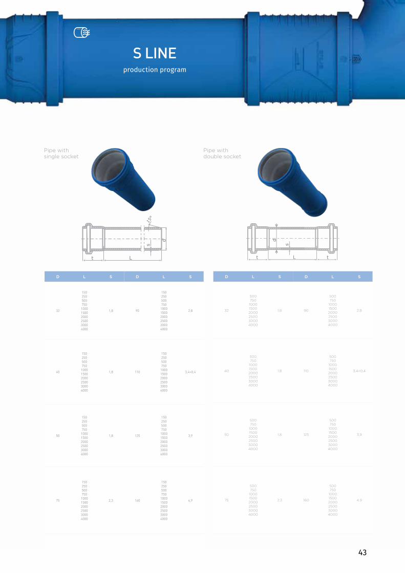
S LINEproduction program
D L S D L S
32
150250500750100015002000250030004000
1,8 90
150250500750100015002000250030004000
2,8
40
150250500750100015002000250030004000
1,8 110
150250500750100015002000250030004000
3,4+0,4
50
150250500750100015002000250030004000
1,8 125
150250500750100015002000250030004000
3,9
75
150250500750100015002000250030004000
2,3 160
150250500750100015002000250030004000
4,9
D L S D L S
32
500750100015002000250030004000
1,8 90
500750100015002000250030004000
2,8
40
500750100015002000250030004000
1,8 110
500750100015002000250030004000
3,4+0,4
50
500750100015002000250030004000
1,8 125
500750100015002000250030004000
3,9
75
500750100015002000250030004000
2,3 160
500750100015002000250030004000
4,9
Pipe with double socket
Pipe with single socket
44
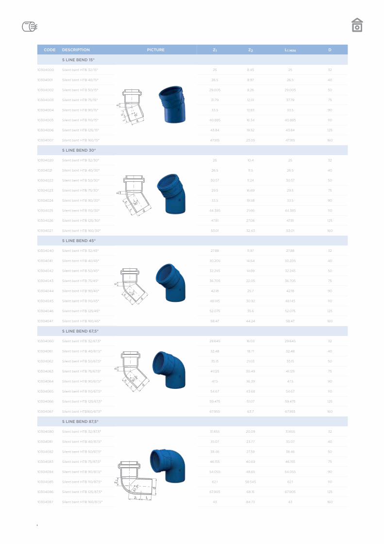
CODE DESCRIPTION PICTURE Z1 Z2 L1 MIN D
S LINE BEND 15°
10304000 Silent bent HTB 32/15° 25 8.45 25 32
10304001 Silent bent HTB 40/15° 26.5 8.97 26.5 40
10304002 Silent bent HTB 50/15° 29.005 8,26 29.005 50
10304003 Silent bent HTB 75/15° 31.79 12.01 37.79 75
10304004 Silent bent HTB 90/15° 33.5 13.83 33.5 90
10304005 Silent bent HTB 110/15° 40.885 16.34 40.885 110
10304006 Silent bent HTB 125/15° 43.84 19.52 43.84 125
10304007 Silent bent HTB 160/15° 47.915 23.05 47.915 160
S LINE BEND 30°
10304020 Silent bent HTB 32/30° 25 10.4 25 32
10304021 Silent bent HTB 40/30° 26.5 11.5 26.5 40
10304022 Silent bent HTB 50/30° 30.57 11.24 30.57 50
10304023 Silent bent HTB 75/30° 29.5 16.69 29.5 75
10304024 Silent bent HTB 90/30° 33.5 19.58 33.5 90
10304025 Silent bent HTB 110/30° 44.385 21.66 44.385 110
10304026 Silent bent HTB 125/30° 47.81 27.06 47.81 125
10304027 Silent bent HTB 160/30° 53.01 32.43 53.01 160
S LINE BEND 45°
10304040 Silent bent HTB 32/45° 27.88 11.97 27.88 32
10304041 Silent bent HTB 40/45° 30.205 14.64 30.205 40
10304042 Silent bent HTB 50/45° 32.245 14.89 32.245 50
10304043 Silent bent HTB 75/45° 36.705 22.05 36.705 75
10304044 Silent bent HTB 90/45° 42.18 25.7 42.18 90
10304045 Silent bent HTB 110/45° 48.145 30.92 48.145 110
10304046 Silent bent HTB 125/45° 52.075 35.6 52.075 125
10304047 Silent bent HTB 160/45° 58.47 44.24 58.47 160
S LINE BEND 67,5°
10304060 Silent bent HTB 32/67,5° 29.645 16.03 29.645 32
10304061 Silent bent HTB 40/67,5° 32.48 18.71 32.48 40
10304062 Silent bent HTB 50/67,5° 35.15 21.03 35.15 50
10304063 Silent bent HTB 75/67,5° 41.125 30.49 41.125 75
10304064 Silent bent HTB 90/67,5° 47.5 36.39 47.5 90
10304065 Silent bent HTB 110/67,5° 54.67 43.68 54.67 110
10304066 Silent bent HTB 125/67,5° 59.475 51.07 59.475 125
10304067 Silent bent HTB160/67,5° 67.955 63.7 67.955 160
S LINE BEND 87,5°
10304080 Silent bent HTB 32/87,5° 31.655 20.09 31.655 32
10304081 Silent bent HTB 40/87,5° 35.07 23.77 35.07 40
10304082 Silent bent HTB 50/87,5° 38.46 27.59 38.46 50
10304083 Silent bent HTB 75/87,5° 46.155 40.69 46.155 75
10304084 Silent bent HTB 90/87,5° 54.055 48.65 54.055 90
10304085 Silent bent HTB 110/87,5° 62.1 58.545 62.1 110
10304086 Silent bent HTB 125/87,5° 67.905 68.15 67.905 125
10304087 Silent bent HTB 160/87,5° 43 84.73 43 160
45
KanalizacijaNiskošumna
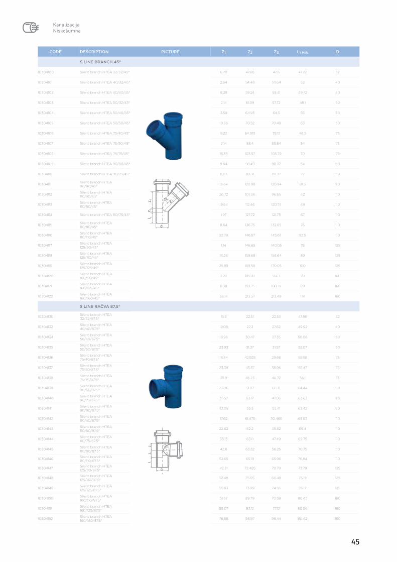
CODE DESCRIPTION PICTURE Z1 Z2 Z3 L1 MIN D
S LINE BRANCH 45°
10304100 Silent branch HTEA 32/32/45° 6.78 47.68 47.6 47.22 32
10304101 Silent branch HTEA 40/32/45° 2.64 54.48 53.64 52 40
10304102 Silent branch HTEA 40/40/45° 8.28 59.24 59.41 49.72 40
10304103 Silent branch HTEA 50/32/45° 2.14 61.09 57.72 48.1 50
10304104 Silent branch HTEA 50/40/45° 3.59 64.95 64.5 55 50
10304105 Silent branch HTEA 50/50/45° 10.36 70.52 70.49 63 50
10304106 Silent branch HTEA 75/40/45° 9.22 84.015 78.12 46.5 75
10304107 Silent branch HTEA 75/50/45° 2.14 88.4 85.84 54 75
10304108 Silent branch HTEA 75/75/45° 15.53 103.97 103.79 70 75
10304109 Silent branch HTEA 90/50/45° 9.64 98.49 90.32 54 90
10304110 Silent branch HTEA 90/75/45° 8.03 113.31 110.37 72 90
10304111 Silent branch HTEA 90/90/45° 18.64 120.98 120.94 81.5 90
10304112 Silent branch HTEA 110/40/45° 26.72 107.36 96.65 42 110
10304113 Silent branch HTEA 110/50/45° 19.64 112.46 120.74 49 110
10304114 Silent branch HTEA 110/75/45° 1.97 127.72 121.75 67 110
10304115 Silent branch HTEA 110/90/45° 8.64 136.75 132.65 76 110
10304116 Silent branch HTEA 110/110/45° 22.78 146.67 145.67 92.5 110
10304117 Silent branch HTEA 125/90/45° 1.14 146.65 140.05 75 125
10304118 Silent branch HTEA 125/110/45° 15.28 159.68 156.64 89 125
10304119 Silent branch HTEA 125/125/45° 25.89 169.58 170.03 100 125
10304120 Silent branch HTEA 160/110/45° 2.22 185.82 174.3 78 160
10304121 Silent branch HTEA 160/125/45° 8.39 193.75 188.78 89 160
10304122 Silent branch HTEA 160/160/45° 33.14 213.57 213.49 114 160
S LINE RAČVA 87,5°
10304130 Silent branch HTEA 32/32/87.5°
15.3 22.51 22.53 47.86 32
10304132 Silent branch HTEA 40/40/87.5° 19.08 27.3 27.62 49.92 40
10304134 Silent branch HTEA 50/40/87.5° 19.96 30.47 27.35 50.06 50
10304135 Silent branch HTEA 50/50/87.5° 23.93 31.37 31.57 52.07 50
10304136 Silent branch HTEA 75/40/87.5° 16.84 42.925 29.66 55.58 75
10304137 Silent branch HTEA 75/50/87.5° 23.39 43.57 35.96 55.47 75
10304138 Silent branch HTEA 75/75/87.5° 35.9 46.23 46.72 56.1 75
10304139 Silent branch HTEA 90/50/87.5° 23.06 51.07 68.31 64.44 90
10304140 Silent branch HTEA 90/75/87.5° 35.57 53.17 47.06 63.63 90
10304141 Silent branch HTEA 90/90/87.5° 43.08 55.3 55.41 63.42 90
10304142 Silent branch HTEA 110/40/87.5° 17.62 61.475 30.465 68.53 110
10304143 Silent branch HTEA 110/50/87.5° 22.62 62.2 35.82 69.4 110
10304144 Silent branch HTEA 110/75/87.5° 35.13 63.11 47.49 69.75 110
10304145 Silent branch HTEA 110/90/87.5° 42.6 63.32 56.25 70.75 110
10304146 Silent branch HTEA 110/110/87.5° 52.65 65.19 65.96 70.84 110
10304147 Silent branch HTEA 125/90/87.5° 42.31 72.485 70.79 73.79 125
10304148 Silent branch HTEA 125/110/87.5° 52.48 75.05 66.48 73.19 125
10304149 Silent branch HTEA 125/125/87.5° 59.83 73.99 74.55 73.17 125
10304150 Silent branch HTEA 160/110/87.5° 51.67 89.79 70.39 80.45 160
10304151 Silent branch HTEA 160/125/87.5° 59.07 93.12 77.12 80.06 160
10304152 Silent branch HTEA 160/160/87.5° 76.58 98.97 98.44 80.42 160
46
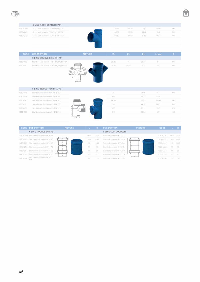
CODE DESCRIPTION PICTURE Z1 Z2 Z3 L1 MIN D
S LINE DOUBLE BRANCH 45°
10304190 Silent double branch HTDA 50/90/50-45° 25.25 45 25.25 54 90
10304191 Silent double branch HTDA 50/110/50-45° 25.25 55.45 25.25 49 110
S LINE INSPECTION BRANCH
10304178 Silent inspection branch HTRE 50 25 31.46 51 50
10304179 Silent inspection branch HTRE 75 37.5 46.74 54.5
10304180 Silent inspection branch HTRE 90 46.44 55.83 62.06 90
10304181 Silent inspection branch HTRE 110 55 66.15 68.5 110
10304182 Silent inspection branch HTRE 125 62.5 75.53 70.5 125
10304183 Silent inspection branch HTRE 160 80 98.78 77 160
CODE DESCRIPTION PICTURE L D DESCRIPTION PICTURE CODE L D
S LINE DOUBLE SOCKET S LINE SLIP COUPLER
10304200 Silent double socket HTM 32 96.9 32.7 Silent slip coupler HTU 32 10304220 96.9 32.7
10304201 Silent double socket HTM 40 104 40.7 Silent slip coupler HTU 40 10304221 104 40.7
10304202 Silent double socket HTM 50 110 50.7 Silent slip coupler HTU 50 10304222 110 50.7
10304203 Silent double socket HTM 75 119 76 Silent slip coupler HTU 75 10304223 119 76
10304204 Silent double socket HTM 90 131 90 Silent slip coupler HTU 90 10304224 131 90
10304205 Silent double socket HTM 110 147 111 Silent slip coupler HTU 110 10304225 147 111
10304206 Silent double socket HTM 125 157 126 Silent slip coupler HTU 125 10304226 157 126
S LINE ARCH BRANCH 87,5°
10304240 Silent arch branch HTEA 90/90/87.5° 52.13 65.85 53 63.07 90
10304241 Silent arch branch HTEA 110/90/87.5° 49.89 77.35 53.42 74.9 110
10304242 Silent arch branch HTEA 110/110/87.5° 60.53 80.51 61.35 74.54 110
47
S LINE ARCH BRANCH 87,5°
10304240 Silent arch branch HTEA 90/90/87.5° 52.13 65.85 53 63.07 90
10304241 Silent arch branch HTEA 110/90/87.5° 49.89 77.35 53.42 74.9 110
10304242 Silent arch branch HTEA 110/110/87.5° 60.53 80.51 61.35 74.54 110
CODE DESCRIPTION PICTURE Z1 L1MIN D D1
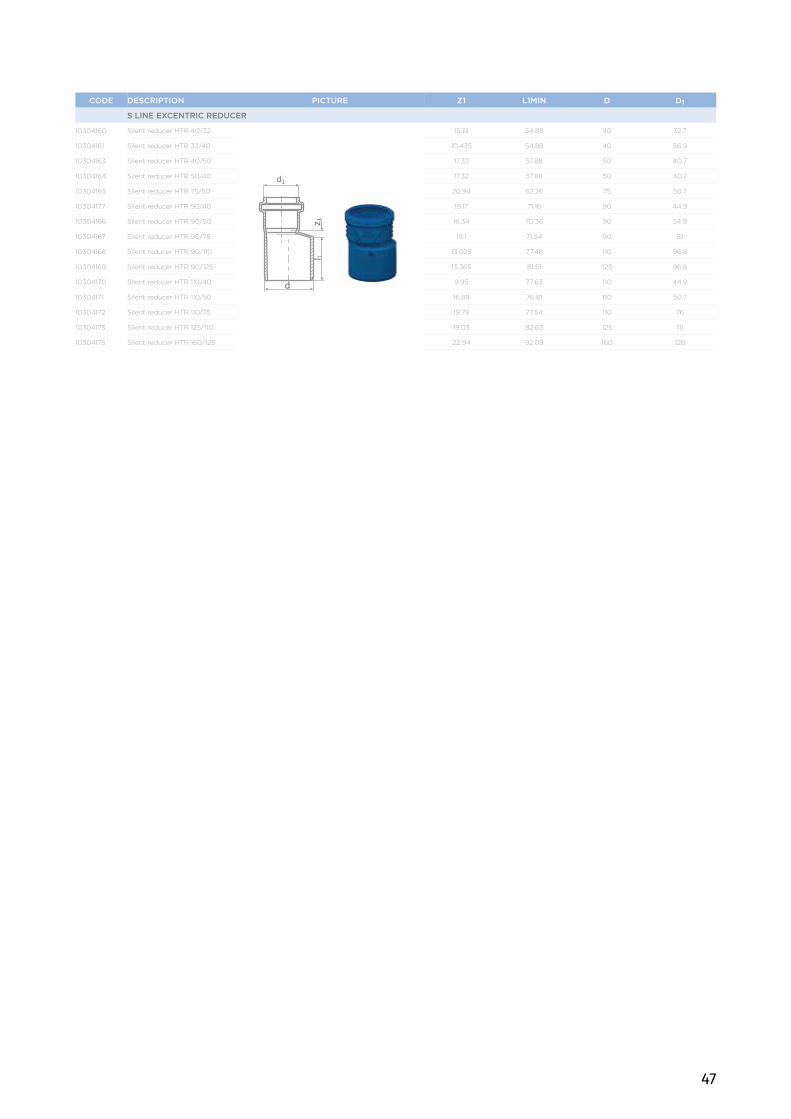
S LINE EXCENTRIC REDUCER
10304160 Silent reducer HTR 40/32 15.19 54.88 40 32.7
10304161 Silent reducer HTR 32/40 10.435 54.88 40 36.9
10304163 Silent reducer HTR 40/50 17.32 57.88 50 40.7
10304164 Silent reducer HTR 50/40 17.32 57.88 50 40.7
10304165 Silent reducer HTR 75/50 20.94 62.26 75 50.7
10304177 Silent reducer HTR 90/40 19.17 71.16 90 44.9
10304166 Silent reducer HTR 90/50 16.34 70.36 90 54.9
10304167 Silent reducer HTR 90/75 19.1 71.54 90 81
10304168 Silent reducer HTR 90/110 13.025 77.48 110 96.8
10304169 Silent reducer HTR 90/125 13.365 81.51 125 96.8
10304170 Silent reducer HTR 110/40 9.95 77.63 110 44.9
10304171 Silent reducer HTR 110/50 16.89 76.81 110 50.7
10304172 Silent reducer HTR 110/75 19.79 77.54 110 76
10304173 Silent reducer HTR 125/110 19.03 82.63 125 111
10304175 Silent reducer HTR 160/125 22.94 92.09 160 126

48