Embed Size (px)
Citation preview

Image brochureTechnical CatalogueLow Voltage Motors


Catalogue_TECO_130412 page 1 of 124
Whilst every care has been taken to ensure the accuracy of the information contained in this publication, due to a policy of continuous product development and improvement we reserve the right to supply products which may differ slightly from those drawn or described in this publication. For critical applications please refer to your local Teco Office.

page 2 of 124 Catalogue_TECO_130412
Table of Contents 1 General .............................................................................................................................................................. 6 1.1 Standards and regulations.................................................................................................................................. 6 1.2 Basics, terms and definitions .............................................................................................................................. 9 1.2.1 Power rating ....................................................................................................................................................... 9 1.2.2 Frame size.......................................................................................................................................................... 9 1.2.3 Mounting arrangement ....................................................................................................................................... 9 1.2.4 Construction and construction material ............................................................................................................ 10 1.2.5 Cooling ............................................................................................................................................................. 11 1.2.6 Degrees of protection ....................................................................................................................................... 11 1.2.7 Performance characteristics: Speed, torque..................................................................................................... 11 1.2.8 Electrical performance characteristics .............................................................................................................. 12 2 AC Motors, European Design........................................................................................................................ 14 2.1 Range of motors covered by this catalogue; variety of characteristics ............................................................. 14 2.2 TECO type code (“Motor Identification Code”).................................................................................................. 15 3 Mechanical design.......................................................................................................................................... 16 3.1 Housing, mounting arrangement ...................................................................................................................... 16 3.2 Terminal box and cable entry ........................................................................................................................... 21 3.3 Cooling ............................................................................................................................................................. 26 3.4 Rotor assembly (active part, shaft, bearings) ................................................................................................... 27 3.4.1 General............................................................................................................................................................. 27 3.4.2 Shaft ................................................................................................................................................................. 28 3.4.3 Bearings ........................................................................................................................................................... 28 3.4.4 Regreasing ....................................................................................................................................................... 32 3.5 Degree of protection ......................................................................................................................................... 33 3.6 Others............................................................................................................................................................... 34 3.6.1 Grounding terminals ......................................................................................................................................... 34 3.6.2 Lifting eyes ....................................................................................................................................................... 34 3.6.3 Drain holes ....................................................................................................................................................... 35 3.6.4 SPM provision .................................................................................................................................................. 35 3.6.5 Painting, corrosion protection ........................................................................................................................... 35 3.6.6 Rating plate and labelling ................................................................................................................................. 36 4 Electrical design ............................................................................................................................................. 37 4.1 Stator winding................................................................................................................................................... 37 4.2 Thermal protection............................................................................................................................................ 39 5 Performance data ........................................................................................................................................... 40 5.1 Duty type .......................................................................................................................................................... 40 5.2 Environmental conditions, performance ........................................................................................................... 40 5.2.1 Operation at high ambient temperature /high altitude....................................................................................... 40 5.2.2 Operation at low temperature /high humidity .................................................................................................... 41 5.2.3 Operation at severe mechanical conditions...................................................................................................... 42 5.3 Mechanical performance .................................................................................................................................. 42 5.3.1 Torque characteristic; starting performance ..................................................................................................... 42 5.3.2 Maximum operational speed............................................................................................................................. 43

Catalogue_TECO_130412 page 3 of 124
5.3.3 Permissible radial shaft forces ..........................................................................................................................44 5.3.4 Permissible axial shaft forces............................................................................................................................46 5.3.5 Vibration............................................................................................................................................................47 5.4 Motor performance (line operated)....................................................................................................................47 5.4.1 Requirements for supply voltage and frequency ...............................................................................................48 5.4.2 Current, power factor and efficiency at partial load ...........................................................................................48 5.4.3 Current during starting, limitations ....................................................................................................................49 5.5 Motor performance (inverter operated) .............................................................................................................51 5.5.1 General .............................................................................................................................................................51 5.5.2 Operational range; principle ..............................................................................................................................52 5.5.3 Operational range for continuous operation ......................................................................................................53 5.5.4 Winding insulation stress ..................................................................................................................................55 5.5.5 Inverter caused bearing currents ......................................................................................................................56 5.5.6 Electromagnetic compatibility............................................................................................................................57 5.5.7 Additional acoustic noise...................................................................................................................................57 6 Technical data .................................................................................................................................................58 6.1 General data; tolerances (acc. to IEC 60034-1)................................................................................................58 6.2 Type data for aluminium version .......................................................................................................................59 6.2.1 Aluminium; 400 V; 50 Hz; Class IE2 .................................................................................................................60 6.2.2 Aluminium; 460 V; 60 Hz; Class IE2 .................................................................................................................64 6.3 Type data for cast iron version..........................................................................................................................68 6.3.1 Cast iron; 400 V; 50 Hz; Class IE2....................................................................................................................68 6.3.2 Cast iron; 400 V; 50 Hz; Class IE3....................................................................................................................72 6.3.3 Cast iron; 460 V; 60 Hz; Class IE2....................................................................................................................75 6.3.4 Cast iron; 460 V; 60 Hz; Class IE3....................................................................................................................79 7 Outline drawings.............................................................................................................................................82 7.1 Aluminium design..............................................................................................................................................82 7.2 Cast iron design ................................................................................................................................................88 7.2.1 Cast iron design; feet version (B3) ....................................................................................................................88 7.2.2 Cast iron design; flange version (B5) ................................................................................................................95 7.2.3 Cast iron design; version with feet and flange (B35) .......................................................................................100 7.2.4 Cast iron design; V1........................................................................................................................................106 8 Spare parts ....................................................................................................................................................113 8.1 Aluminium motors ...........................................................................................................................................113 8.2 Cast iron motors..............................................................................................................................................115 9 Packing, labelling..........................................................................................................................................119 9.1 Packing design................................................................................................................................................119 9.1.1 Motors up to frame size 90..............................................................................................................................119 9.1.2 Motors frame size 100 to 315..........................................................................................................................120 9.2 Labelling..........................................................................................................................................................120 10 Quality assurance .........................................................................................................................................121 11 Documentation..............................................................................................................................................122

page 4 of 124 Catalogue_TECO_130412
TECO History 1956 Company foundation and start of production in the first TECO factory in San-Chung, TAIWAN 1965 Production capacity increased by opening new factory in Shin-Chuan, TAIWAN 1966 Start of close technical co-operation with Hitachi, Yaskawa and Taiyo 1979 Further production capacity increase by opening a factory in Chung Li, TAIWAN Plant I (Heavy Motor Plant) 1987 Opened Chung Li Plant II for serial motor production (Small Motor Plant) 1987 Started Joint Venture with Westinghouse Motor Company, USA, one of the leading motor manufacturers in
North America 1991 Foundation of TECO Perai, Penang Provence, MALAYSIA, to serve the local market with low voltage motors 1995 100% take over of Westinghouse motor business by TECO.
Foundation of TECO Westinghouse Motor Company 2000 Opened TECO factory for low voltage motors in Suzhou, Jiangsu Provence, CHINA 2003 Opened TECO factory for low and medium voltage motors in Wuxi, CHINA 2005 Opened third TECO factory in Nanchang, Jiangxi Provence, CHINA 2006 Opened factory in Huyen Long Thanh, Tinh Dong Nai Provence, VIETNAM to increase local business 2008 Opened TECO repair and assembling plant in Dammam, KINGDOM OF SAUDI ARABIA, on joint venture basis 2008 Established TECO Fuan in Fujian Provence, CHINA, with a decision for construction of a new plant 2010 Starting the production of aluminium motors and semi finished aluminium parts at TECO Fuan factory
In Fujian Provence, CHINA TECO Actual In 2010 TECO with 30 subsidiaries worldwide and affiliates gained a turnover of 1 Billion EURO achieved with approximately 10.000 employees worldwide. More than 50% of the turnover was generated by the Electric Motor business. TECO is listed as reference value on the stock exchange in Taipei, TAIWAN. The detailed financial data can be downloaded from the TECO website http://www.teco.com.tw/en_version under “investor relations”. TECO is mainly focused on - Sustainable development with new competitive advantages - Enhancing service quality - Development and education of experienced employees - Creating outstanding products TECO has - Significant Experience in the Motor Industry - Experienced Engineering and Manufacturing Staff - State of the art factories in the most important manufacturing markets - State of the Art Testing Facilities for the full power and voltage range of its motors TECO Europe TECO EUROPE have been established since 1993 and have offices in the UK, Netherlands, Germany, France, Italy, Spain and Switzerland. As a wholly owned subsidiary of the multinational TECO Electric and Machinery Co. Ltd. of Taiwan and having acquired Westinghouse Motors in 1993 we are part of the 3rd largest global electric motor manufacturer. TECO is currently a $12.6B turnover organisation in diverse business sectors such as Factory Automation, Telecoms, Consumer Electronics and Restaurants. Within the European Operation we have stocks of motors and drives in Germany, the UK and the Netherlands and a comprehensive network of specialist distributors, so whatever your motor and drive requirement our experienced engineering team can help and advise on the correct products to suit your applications. References in this catalogue: - TECO Manual “INSTALLATION, OPERATION and MAINTENANCE INSTRUCTIONS FOR TECO LOW VOLTAGE
MOTORS Type ALAA and ALCA” - TECO short form safety instructions

Catalogue_TECO_130412 page 5 of 124
TECO Scope of Supply:
Cast Iron Aluminium
Three Phase Asynchronous Motors
Open Drip Proof IE2 Cast Iron IE3 Cast Iron IE2 Aluminium IE3 Aluminium
High Efficiency Motors
NEMA Premium Efficiency Capacitor-Start Capacitor-Start, Capacitor Run Single Phase Motors Split Phase Start Non Sparking Flameproof Increased Safety
Explosion Proof Motors
Dust Ignition Proof Solid Shaft High Thrust
Vertical Motors Hollow Shaft High Thrust Inverter Duty Pole Changing Smoke Extraction Brake Motor Marine Duty Extended Shaft End Double Shaft End Hollow Shaft Crusher Duty Submersible Crane Duty Wind Generator Cooling Fan Design
Special Purpose Motors
Pump jack (Oil Well) Design 0.4 - 1000kW 200, 400, 690V Constant /Variable Torque models IP00, IP20, IP54, IP65
3 Phase Drives
V/F and Flux Vector 0.18-2.2kW IP20 and IP65
Lo
w V
olt
age
0,12
to
100
0 k
W
Single Phase Drives V/F and Flux Vector Asynchronous Synchronous 3 Phase Motors Slip ring Non Sparking Flameproof Increased Safety
Explosion Proof Motors
Dust Ignition Proof Solid Shaft High Thrust
Vertical Motors Hollow Shaft High Thrust Inverter Duty Pole Changing Marine Duty Extended Shaft End Double Shaft End Crusher Duty
Hig
h V
olt
age
0,
315
to 4
5 M
W
Special Purpose
Wind Generator Wound Rotor Induction Motors
Permanent Magnet Motors Series Type Shunt Type S
pec
ial
Des
ign
DC Motors Compound Type

General
page 6 of 124 Catalogue_TECO_130412
1 General
1.1 Standards and regulations There are different international standards for electrical machines, e.g. - the international “IEC” standard or - the North American “NEMA”- standard and others.
The motors covered by this catalogue are designed and manufactured according to the latest IEC standards. Furthermore they fulfil the relevant regulations of the European Community (“EC Regulations”).
List of national and international standards and regulations applied:
Title International IEC Europe EN/Directive Germany DIN/VDE
Rotating electrical machines - Part 1: Rating and performance
60 034-1 60 034-1 DIN EN 60 034-1 VDE 0530 Part 1
Rotating electrical machines - Part 2-1:Standard methods for determining losses and efficiency from tests
60 034-2-1:2007 60 034-2-1:2007 DIN EN 60 034-2 VDE 0530 Part 2
Rotating electrical machines - Part 5: Degrees of protection provided by the integral design of rotating electrical machines (IP code) - Classification
60 034-5 60 034-5 DIN EN 60 034-5 VDE 0530 Part 5
Rotating electrical machines - Part 6: Methods of cooling (IC Code)
60 034-6 60 034-6 DIN EN 60 034-6 VDE 0530 Part 6
Rotating electrical machines - Part 7: Classification of types of construction, mounting arrangements and terminal box position (IM Code)
60 034-7 60 034-7 DIN EN 60 034-7 VDE 0530 Part 7
Rotating electrical machines - Part 8: Terminal markings and direction of rotation
60 034-8 60 034-8 DIN EN 60 034-8 VDE 0530 Part 8
Rotating electrical machines - Part 9: Noise limits
60 034-9 60 034-9 DIN EN 60 034-9 VDE 0530 Part 9
Rotating electrical machines - Part 11: Thermal protection
60 034-11 60 034-11
Thermistors, PTC DIN 44081:1980-6
Rotating electrical machines - Part 12: Starting performance of single-speed three-phase cage induction motors
60 034-12 60 034-12 DIN EN 60 034-12 VDE 0530 Part 12
Rotating electrical machines - Part 14: Mechanical vibration of certain machines with shaft heights 56 mm and higher - Measurement, evaluation and limits of vibration severity
60 034-14 60 034-14 DIN EN 60 034-14 VDE 0530 Part 14
Rotating electrical machines - Part 17: 3)
Cage induction motors when fed from converters- Application guide
TS 60034-17
Mechanical vibration; balancing shaft and fitment key convention
DIN ISO 8821
Mechanical vibration - Balance quality requirements for rotors in a constant (rigid) state - Part 1: Specification and verification of balance tolerances
DIN ISO 1940-1:2004-04

General
Catalogue_TECO_130412 page 7 of 124
Title International IEC Europe EN/Directive Germany DIN/VDE
Rotating electrical machines - Part 30: Efficiency classes of single-speed, three-phase, cage-induction motors (IE-code)
60 034-30
IEC standard voltages 60 038 - DIN IEC 60 038
Dimensions and output series for rotating electrical machines - Part 1: Frame numbers 56 to 400 and flange numbers 55 to 1080
60 072-1 1) 50 347 DIN EN 50 347 2)
Electrical insulation - Thermal evaluation and designation
60 085 - DIN IEC 60 085
Safety of electrical Machines – Electrical equipment of Machines Part 1: Common Requirements
60 204-1 60 204-1 DIN EN 60 204-1 VDE 0113-1
Electro technical graphical symbols 60 617-2 60 617-2 DIN EN 60 617-2
Drive Type Fastenings without Taper Action; Parallel Keys, Keyways, Deep Pattern
DIN 6885-1
Hexagonal screws DIN EN ISO 4014
Hexagonal nuts DIN EN ISO 4032
Lubricating nipples; button head
DIN 3404
Protection of steel structures from corrosion by organic and metallic coatings
DIN 55 928
Low Voltage Directive 2006/95/EC 2006/95/EC
EMC Directive 2004/108/EC 2004/108/EC
Machinery Directive 2006/42/EC 4) 2006/42/EC
1) Applicable for dimensions and frame sizes only 2) Applicable for single speed motors up to frame size 315M only 3) As far as applicable 4) not directly applicable for low voltage motors
Table 1-1: Standards and regulations applied

General
page 8 of 124 Catalogue_TECO_130412
Remarkable latest innovations in above mentioned standards are - IEC 60034-2-1 (...standard methods for determining losses and efficiency from tests) and - IEC 60034-30 (...efficiency classes of single-speed, three-phase cage-induction motors; IE-code). By IEC 60034-2-1 an improved procedure for testing of the efficiency is described. In general the nominal efficiency evaluated by this method is slightly lower than the value based on the formerly used procedure. IEC 60034-30 defines classes of efficiency for standard motors (“International Efficiency”): “IE1” (Standard Efficiency), “IE2” (High Efficiency), “IE3” (Premium Efficiency) and “IE4” (Super Premium efficiency). These efficiency class definitions demand a minimum efficiency value depending on power rating and pole number of the motor. (This classification replaces the formerly used efficiency class definitions like e.g. “eff1”.) The motors in this catalogue (category IE2 and IE3) fulfil ore override these minimum levels. Depending on local regulations the current and future use of these advanced motors is mandatory. The current regulation within the European Community is EG 640/2009, as a part of the EU’s eco-design project. It covers 2-, 4-, 6- and 8-pole three phase low voltage induction motors with power rating from 0,75 kW up to 375 kW (excepted of special motors like explosion proof motors and others). Schedule for mandatory use of these motors: - June 2011: efficiency class IE2 for all motors covered by this regulation - January 2015: efficiency class IE3 for motors from 7,5 kW up to 375 kW ( or IE2 if inverter operated) - January 2017: efficiency class IE3 for all motors from 0,75 kW up to 375 kW (or IE2 if inverter operated). A sample for efficiency requirements is given in the figure below (4-pole motors, classification “IE2” and “IE3”):
Figure 1-1: Minimum nominal efficiency for 4-pole motors acc. class IE2 and IE3 (IEC 60034-30)
79,6
81,4
82,8 84,3
85,5 86,6
87,7 88,7
89,8 90,6 91,2
91,692,3 92,7 93,1 93,5
94 94,2 94,594,7 94,9 95,1 95,1 95,1
82,5
84,1
85,3 86,7
87,7 88,6
89,6 90,4 91,4 92,1
92,6 9393,6 93,9 94,2 94,6
95 95,2 95,4 95,6 95,8 96 96 96
75
80
85
90
95
100
0,75 1,1 1,5 2,2 3 4 5,5 7,5 11 15 18,5 22 30 37 45 55 75 90 110132160200250315
efficiency [%]
power rating
Class IE2
Class IE3
General
Catalogue_TECO_130412 page 9 of 124
1.2 Basics, terms and definitions Induction machines are the commonly most used motor type for general drive applications. They are extremely durable and robust and provide an economic drive solution, even under severe environmental conditions. They can be used for direct line operation (fixed speed) or in combination with a frequency inverter (variable speed drive system). They are available in a lot of varieties. Some typical characteristics are listed below:
1.2.1 Power rating The power rating of electrical motors refers to the mechanical shaft output power (in opposite: for electrical generators the rating refers to the electrical power at the terminals.) Within the IEC standard range (up to 315 kW) standardized values for the rating are defined (e.g. 37 kW, 45 kW etc.).
1.2.2 Frame size The frame size is defined as the distance [mm] between the mounting level and the centre of the shaft (in case of floor mounted arrangement; accordingly a definition is stated for flange mounted arrangement). Standard values for the frame sizes are defined for the IEC standard range (e.g. frame size 200, 225 etc.). In addition a fixed coordination between power rating and frame size is defined in IEC 60072-1. Within a defined frame size several types can be designed with different lengths.
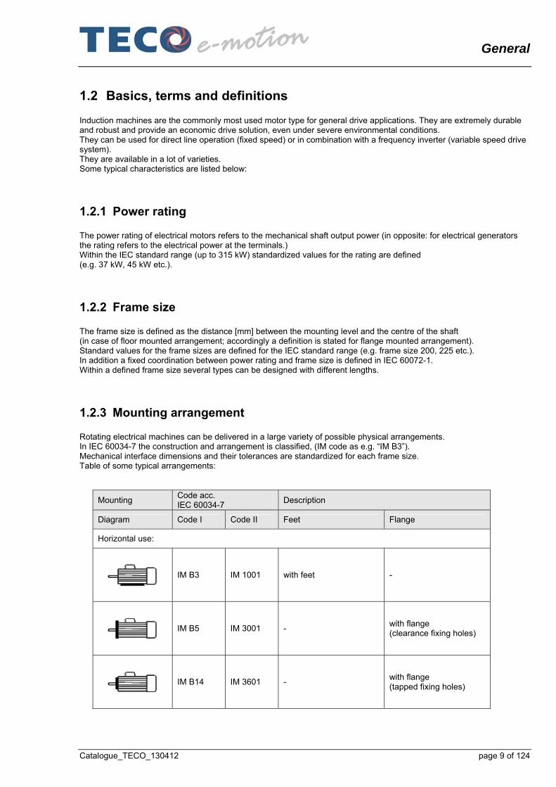
1.2.3 Mounting arrangement Rotating electrical machines can be delivered in a large variety of possible physical arrangements. In IEC 60034-7 the construction and arrangement is classified, (IM code as e.g. “IM B3”). Mechanical interface dimensions and their tolerances are standardized for each frame size. Table of some typical arrangements:
Mounting Code acc. IEC 60034-7
Description
Diagram Code I Code II Feet Flange
Horizontal use:
IM B3 IM 1001 with feet -
IM B5 IM 3001 -
with flange (clearance fixing holes)
IM B14 IM 3601 -
with flange (tapped fixing holes)

General
page 10 of 124 Catalogue_TECO_130412
Mounting Code acc. IEC 60034-7
Description
Diagram Code I Code II Feet Flange
IM B34 IM 2101 with feet
with flange (tapped fixing holes)
IM B35 IM 2001 with feet
with flange (clearance fixing holes)
Vertical use:
IM V1 IM 3011 -
with flange (clearance fixing holes) shaft up
IM V3 IM 3031 -
with flange (clearance fixing holes) shaft down
IM V5 IM 1011 with feet shaft down
-
IM V6 IM 1031 with feet shaft up
-
Table 1-2: Relevant IM arrangements (selection)
1.2.4 Construction and construction material The relevant components are: - Stator housing with active stator parts inside (magnetic core, stator winding), - End shields with bearings, - Shaft with active rotor parts (magnetic core, squirrel cage), - Cooling system, - Terminal box. Housing, end shields and terminal box can be manufactured in aluminium (preferable at small machines), cast iron (medium size machines) or welded steel (large machines).

General
Catalogue_TECO_130412 page 11 of 124
1.2.5 Cooling Cooling can be carried out either with ambient air or with cooling water with a large variety of detailed constructions. Principle arrangements of the cooling are defined in IEC 60034-6 (IC code). In the range of IEC standard motors as presented in this catalogue the cooling system in general is “IC 411”¨: Totally Enclosed Surface Fan cooled (“TEFC”) as shown in the sample picture above.
1.2.6 Degrees of protection The level of protection against environmental conditions like water, dust, etc. is defined in 60034-5 (IP code as e.g. “IP55”). The user has to choose a sufficient degree of protection according to his environmental conditions.
1.2.7 Performance characteristics: Speed, torque (Only induction motors with a rotor in “squirrel cage” design regarded here; no “wound rotor” types). If operated at a grid with fixed voltage and frequency the nominal speed (“full load speed”) is near to the “no-load speed” (also called “synchronous speed”): this is defined by the grid frequency and the “pole number” of the motor (also called “2p” with “p” as the number of pole pairs):
Motor design 2-pole 4-pole 6-pole 8-pole
No load speed at 50 Hz grid 3000 rpm 1500 rpm 1000 rpm 750 rpm
No load speed at 60 Hz grid 3600 rpm 1800 rpm 1200 rpm 900 rpm
Table 1-3: No load speed The starting performance is standardized by IEC 60034-12 (“Starting performance of single-speed three-phase cage induction motors”). The motors covered by this catalogue comply with “IEC 60034-12, Design N”. The typical characteristic of the torque versus speed is shown in the diagram below:
Figure 1-2: Typical characteristic for induction motors: Torque versus speed

General
page 12 of 124 Catalogue_TECO_130412
Characteristic points which are content of the type data: - Full load speed (“nominal speed”) - Full load torque (“nominal torque”) - Locked rotor torque (“starting torque”) ; as a multiple of nominal - Pull up torque ; as a multiple of nominal - Breakdown torque; as a multiple of nominal.
1.2.8 Electrical performance characteristics According to 1.2.7 Performance characteristics: Speed, torque the typical characteristic of current and power factor is shown in the diagram below:
Figure 1-3: Typical characteristic for induction motors: Torque and current versus speed Characteristic points which are content of the type data (see 6 Technical data, starting page 58): - Full load current (“nominal current”) - Full load power factor - Locked rotor current; as a multiple of nominal.
General
Catalogue_TECO_130412 page 13 of 124
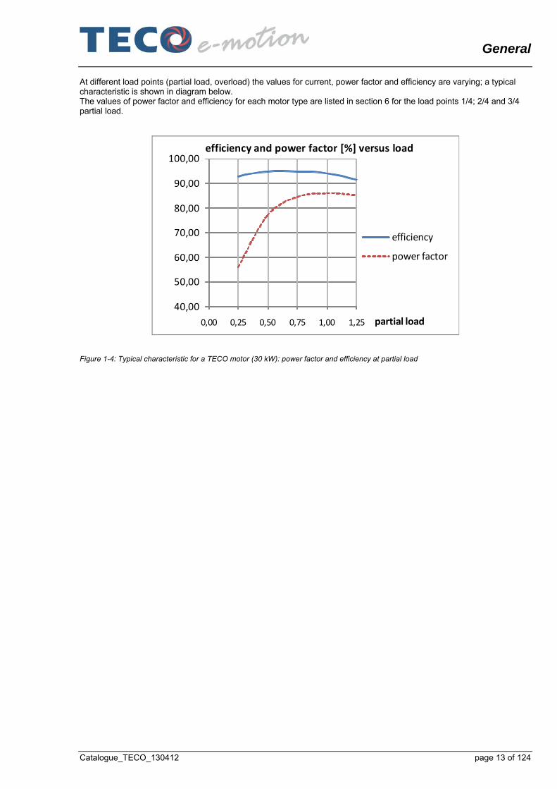
At different load points (partial load, overload) the values for current, power factor and efficiency are varying; a typical characteristic is shown in diagram below. The values of power factor and efficiency for each motor type are listed in section 6 for the load points 1/4; 2/4 and 3/4 partial load.
40,00
50,00
60,00
70,00
80,00
90,00
100,00
0,00 0,25 0,50 0,75 1,00 1,25 partial load
efficiency and power factor [%] versus load
efficiency
power factor
Figure 1-4: Typical characteristic for a TECO motor (30 kW): power factor and efficiency at partial load

AC Motors, Europe Design
page 14 of 124 Catalogue_TECO_130412
2 AC Motors, European Design
2.1 Range of motors covered by this catalogue; variety of characteristics
Common characteristics Three phase low voltage motors according to IEC standard, single speed, totally enclosed, for Standard Safe Area
Power rating 0,18 kW - 315 kW
Frame size 63 – 315
Pole number 2-pole; 4-pole; 6-pole; 8-pole
Line Frequency 50 Hz; 60 Hz
Type of mounting Feet version, flange version and combinations
Construction material Aluminium or Cast Iron
Efficiency class acc. IEC Cast iron motors: IE2 and IE3 (identical dimensions) Aluminium motors: IE 2
Accessories Standard or with options (e. g. forced ventilation)
Standards IEC standards, European directives (CE marking).
Compliance with additional regulations for applications “non essential service”: “GL Rules and guidelines 2011” “BV Rules and guidelines 2011” “LR Rules and Regulations for the classification of ships, 2011” “DNV Rules for Ships/High Speed, Light Craft and Naval Surface Craft, January 2011”
Table 2-1: Motors covered by this catalogue

AC Motors, Europe Design
Catalogue_TECO_130412 page 15 of 124
2.2 TECO type code (“Motor Identification Code”) The type code is covering the overall range of TECO induction motors. It is explained for a sample motor type “ALCA-0160MC-30004-IZ”: A low voltage 3 phase AC motor for application in “Safe Area”, with aluminium housing; frame size 100; 4-pole; according IEC standards; optional version with accessories.
A L C A - 0 1 0 0 L 2 - 1 0 0 0 4 - I Z
Digit No. 1 2 3 4 5 6 7 8 9 10 11 12 13 14 15 16 17 18 19 20
Attribute No. 1 2 3 4 5 8 9 11 12 13
No. Attribute Character SpecificationA Standard Safe AreaF Flameproof "Ex d(e)"G Generator Synchronous Standard Safe AreaI Increased Safety "Ex e"N Non Sparking "Ex n"P Pressurized "Ex p"S SmokespillZ SpecialH High Voltage 3~L Low Voltage 3~S Low Voltage 1~Z SpecialA Aluminum Mould CastB Aluminum String CastC Cast IronR Rolled SteelW Welded SteelZ SpecialA IC 411 TEFC Totally Enclosed Surface Fan CooledB IC 511 Tube CooledC IC 611 Air to Air Heat ExchangerF IC 416 TEFV Totally Enclosed Forced VentilationK IC 410 TENV Totally Enclosed Non Ventillated (Convection)O IC 01 Open Circuit VentilationW IC 81W Water to Air Heat ExchangerZ Special
563upto
9000AuptoXX
81 Single Speed2 2-times Pole Changing3 3-times Pole Changing246upto
128411
7 Core Length
9 Poles
10 Poles
6 Frame Size
3 Frame Material
4 Cooling
10
1 Design
2 Voltage
6 7
Type Key / Motor Identification Code / Type Code
Remarks for digits 13 to 17: “31284” e.g. is defined as “3 speed, with 12 pole, 8 pole and 4 pole winding”.
Table 2-2: TECO type code

Mechanical design
page 16 of 124 Catalogue_TECO_130412
3 Mechanical design
3.1 Housing, mounting arrangement All construction components are shown for a sample motor in the figure below:
01 Shaft cover 15 Feet 29 Terminal box gasket 02 Oil Seal 16 Washer 30 Terminal box cover 03 Outer bearing cover 17 Eye bolt 31 Earth terminal assy. 04 Grease drain cover 18 Name plate carrier 32 Inner bearing cover 05 End shield DE 19 Name plate 33 Bearing stop ring 06 Grease nipple 20 Terminal box plate 34 Bearing 07 Bearing 21 Blind plug 35 Pre-load spring 08 Bearing stop ring 22 Terminal box housing 36 End shield NDE 09 Inner bearing cover 23 Fixed seat 37 Grease nipple 10 Shaft 24 Power connecting assy 38 Grease drain cover 11 Key 25 Earth terminal assy. 39 Outer bearing cover 12 Rotor 26 Power terminals 40 Oil seal 13 Stator 27 Hex nut 41 External fan 14 Frame 28 Star-Delta jumpers 42 Fan cowl
Figure 3-1: “Exploded” drawing of a sample TECO motor

Mechanical design
Catalogue_TECO_130412 page 17 of 124
The motors are available in the versions: - Aluminium housing (type code e.g. “ALAA-......) or - Cast iron housing (type code e.g. “ALCA-......).
Power ratings Depending on pole number, see 6 Technical data, starting page 58.
Frame size 63 71 80 90 100 112 132 160 180 200 225 250 280 315
Aluminium X X X X X X X X
Cast iron X X X X X X X X X X X X
Table 3-1: Motor versions available The motors can be delivered for many types of mounting: - Feet version (IM code B3, suitable for arrangements B6, B7, B8, V5, V6); with top mounted terminal box (standard
configuration) - Flange version with clearance fixing holes (IM code B5, suitable for arrangements V1 and V3) or - Flange version with tapped fixing holes (IM code B14, suitable for arrangements V18 and V19) or - Version with feet and flange with clearance fixing holes (IM code B35, suitable for V15 and V36 or - Version with feet and flange with tapped fixing holes (IM code B34).
To be regarded only for motors with frame size 315; 2-pole: Vertical use (V- mountings) is only admissible in a special design; this has to be defined in the order.
Figure 3-2: Sample of a TECO motor (feet version)

Mechanical design
page 18 of 124 Catalogue_TECO_130412
Figure 3-3: Sample of a TECO motor (flange version) Dimensions: All external dimensions of the motor (shaft height, length) for a defined motor rating are identical for the IE2- and the IE3- version. This allows variability for the user depending on the application. The dimensions and tolerances for the mechanical interface (e. g. positions of feet holes) are defined by IEC 60072-1. Multi-mount symmetric design - Axial direction: The motor housing is designed to allow for a large variety of mounting arrangements. It is symmetric in axial direction (DE – NDE), except of the asymmetric position of the terminal box. Therefore the user can change the axial position of the terminal box according to the individual spatial conditions at his construction (front or back) by changing the position of the rotor including DE and NDE end shield. Due to a special design of the DE end shield this modification can be carried out without dismantling the NDE assembly. (To be regarded when carrying out this modification: the rotational direction of the motor is no longer acc. to IEC 60034-8 then. Precautions shall be made to prevent disturbances. Modification of mounting arrangement shall only be carried out by qualified personnel; regard the guidelines in the TECO manual “INSTALLATION, OPERATION and MAINTENANCE INSTRUCTIONS....”)
Figure 3-4: Multi- mount design (in axial direction); terminal box “Drive End”

Mechanical design
Catalogue_TECO_130412 page 19 of 124
Figure 3-5: Multi- mount design (in axial direction); terminal box “Non drive end” SDF As a standard the “feet”- in SDF version (B3; B34; B35) are delivered with a top mounted terminal box. In the “Standard Detachable Feet” (SDF) version; the feet can be detached if required. ADF In the optional version “Advanced Detachable Feet; (ADF) the housing is machined to be able to move the feet in 3 x 90° positions. Therefore the feet can easily be mounted in each of the 3 rotational positions and the 2 axial positions. All surfaces and all fixing holes for mounting the feet are machined, drilled, tapped and plugged. The holes (as well as others e.g. for lifting lugs, etc.) are designed as blind holes. If using the original feet a change of the feet position is possible without new alignment of the motor when feet are fixed in the new position.
Figure 3-6: Multi-mount design (top mounted terminal box)

Mechanical design
page 20 of 124 Catalogue_TECO_130412
Figure 3-7: Multi-mount design (terminal box in left hand side position)
Figure 3-8: Multi-mount design (terminal box in right hand side position) Details for flange version Possible mounting arrangements according to IEC 60034-7: B5, V1, V3. All customer interface dimensions (hole circle diameter, centring diameter, etc.) and their tolerances are defined by IEC 60072-1. For a number of motor frame sizes as an option flanges with external dimensions equivalent to larger or smaller frame sizes are available on request; see tables:
Available FF(A)-Flanges (clearance fixing holes)
Frame size
FF [mm] 100 115 130 165 215 265 300 350 400 500 600 740 940
A [mm] 120 140 160 200 250 300 350 400 450 550 660 800 1000
63 X X
71 X X
80 X X
90 X X
100 X X
112 X X
132 X X
160 X X
180 X

Mechanical design
Catalogue_TECO_130412 page 21 of 124
Available FF(A)-Flanges (clearance fixing holes)
Frame size
FF [mm] 100 115 130 165 215 265 300 350 400 500 600 740 940
A [mm] 120 140 160 200 250 300 350 400 450 550 660 800 1000
200 X
225 X
250 X
280 X
315 X
FF= hole circle X= standard
A= diameter X= available on request Table 3-2: Flange sizes available (B5; clearance fixing holes)
Available FT(C)-Flanges (tapped fixing holes)
Frame size
FT [mm] 65 75 85 100 115 130 165 215
C [mm] 80 90 105 120 140 160 200 250
63 X X X
71 X X X
80 X X X
90 X X X
100 X X X
112 X X X
132 X X X
160 X X
180 X
FT= hole circle X= standard
C= diameter X= available on request Table 3-3: Flange sizes available (B14; tapped fixing holes)
3.2 Terminal box and cable entry As a standard the motors are delivered with a top mounted terminal box; located at the drive end, with cable entry to the right hand side. As described in 3.1 Housing, mounting arrangement, the position of the terminal box can easily be varied (left, right, front or back). Furthermore the terminal box itself is able to be rotated by steps of 90° to every direction to enable power cable entry from 4 directions (front, rear, left, right). (Guidelines for proper modification of the terminal box position: see TECO manual “INSTALLATION, OPERATION and MAINTENANCE INSTRUCTIONS....”)

Mechanical design
page 22 of 124 Catalogue_TECO_130412
Figure 3-9: Cable entry front Figure 3-10: Cable entry back
Figure 3-11: Cable entry left Figure 3-12: Cable entry right There are two cable entry holes for the power supply cable(s) and one entry hole for the cable for auxiliary devices, e. g. for thermistor connection. They are drilled, tapped and properly sealed; with threads according to table below. (The applicable cable outer diameter is dependent on the customer’s cable gland type.) All six winding lead ends from the windings are brought out and connected to a terminal block with metric threaded bolts for smaller motors or to metric duct connection bolts for bigger motors. Screws and nuts are hexagonal with metric thread and with ISO wrench sizes acc. to DIN EN ISO 4014 (screws) and DIN EN ISO 4032 (nuts). Three jumpers are attached to enable the customer a simple star or delta connection (see 4 Electrical design, starting page 37). The lead ends of the standard thermistors (as well as optional accessories like space heaters) are connected to terminals (luster terminals or spring loaded serial terminals, see table below).

Mechanical design
Catalogue_TECO_130412 page 23 of 124
The terminals are marked and directed according to IEC 60034-8 A connection diagram sticker with the wiring diagram is fitted on the inside of the terminal box lid. ALAA, cable entries for power and thermistors:
Frame size
Power Supply Thermistor
Threads Power connector
bolts Threads
Type of Connector
63 2 x M16 x 1.5 U-clamp Luster terminal
71 2 x M16 x 1.5 U-clamp Luster terminal
80 2 x M16 x 1.5 U-clamp Luster terminal
90 2 x M25 x 1,5 U-clamp Luster terminal
100 2 x M25 x 1.5 U-clamp Luster terminal
112 1 x M32 x 1.5 U-clamp 1 x M25 x 1.5 Luster terminal
132 1 x M32 x 1,5 U-clamp 1 x M25 x 1.5 Luster terminal
160 2 x M40 x 1,5 Bolts 1 x M20 x 1.5 Serial terminal
ALCA, cable entries for power and thermistors:
Frame size
Power Supply Thermistor
Threads Power connector
bolts Threads
Type of Connector
63 1 x M20 x 1.5 U-clamp M16 x 1.5 Luster terminal
71 1 x M20 x 1.5 U-clamp M16 x 1.5 Luster terminal
80 2 x M25 x 1,5 U-clamp M20 x 1.5 Luster terminal
90 2 x M25 x 1,5 U-clamp M20 x 1.5 Luster terminal
100 2 x M32 x 1,5 U-clamp M20 x 1.5 Luster terminal
112 2 x M32 x 1,5 U-clamp M20 x 1.5 Luster terminal
132 2 x M32 x 1,5 U-clamp M20 x 1.5 Luster terminal
160 2 x M40 x 1,5 Bolts M20 x 1.5 Serial terminal
180 2 x M40 x 1,5 Bolts M20 x 1.5 Serial terminal
200 2 x M50 x 1,5 Bolts M20 x 1.5 Serial terminal
225 2 x M50 x 1,5 Bolts M20 x 1.5 Serial terminal
250 2 x M63 x 1,5 Bolts M20 x 1.5 Serial terminal
280 2 x M63 x 1,5 Bolts M20 x 1.5 Serial terminal
315 2 x M63 x 1,5 Bolts M20 x 1.5 Serial terminal
Table 3-4: Cable entries and connectors Detailed mechanical dimensions depending on motor type: see 7 Outline drawings, starting page 82.

Mechanical design
page 24 of 124 Catalogue_TECO_130412
Options, on request: From frame size 160 to 250 an optional attachment of one and from frame size 280 to 400 of two separate accessory terminal boxes is available. (e.g.: different terminal boxes for different voltage levels may be demanded by customer specifications). The motors can also be delivered without a terminal box on request. In this case we provide a blind plate with bushing for direct entry of customer specified cable(s).
Figure 3-13: Position of cable entries (up to frame size 132) Frame size 160 and above are equipped with a detachable steel plate on one side of the terminal box (cable entry plate). This is to enable customers an easy power supply connection and simple replacement of the motors with bulky cables as well as for later flexibility if customer asks for special amount of cable entry holes with special threads (special cable size or number of cables).

Mechanical design
Catalogue_TECO_130412 page 25 of 124
In these cases TECO can manufacture customized entry plates or blank plates on demand. Customer’s cable glands: Insure the cable glands used are rated to an equal or better protection class than the motor.
Figure 3-14: Position of cable entries (ALCA, frame size 160 to 315)

Mechanical design
page 26 of 124 Catalogue_TECO_130412
Figure 3-15: Detached entry plate
3.3 Cooling As a standard the motors covered by this catalogue are “Totally Enclosed Surface Fan Cooled” (“TEFC”) acc. to the IEC code “IC 411”. This design provides cooling fins on the surface of the motor housing and a fan (and fan cowl) at NDE to generate a cooling air flow over these fins from NDE to DE. Even though acoustic noise is optimized, the fan is suitable for application in both directions of rotation (“bidirectional design”). The fan cowl is manufactured in steel sheet.
Figure 3-16: Cooling principle (“TEFC”)
Mechanical design
Catalogue_TECO_130412 page 27 of 124
In accordance with IEC standards the degree of protection for the cooling system is IP 20 (even though the motor is classified in a much higher degree of protection, in this case IP 55). The cooling system allows operation in any mounting position in principle. When mounted in a “shaft down position” precautions are required to prevent foreign bodies or excessive amount of water falling into the openings of fan. An accessory kit “Protection cover for shaft down motors” is available on request; it can be added easily in site. The user has to take care that the air flow is not hindered or a high back pressure is generated when integrating the motor into his machine. As a general rule e.g. the distance between air inlet of motor and obstruction should be at least ¼ of the air inlet diameter of the fan cowl. Options: - A special design with “uni- directional” fan for acoustic noise reduction is available on request. In this case a sticker is
mounted at the top of the front end shield which clearly indicates the direction of rotation. (acoustic noise level: see 5.3 Mechanical performance, starting page 42.
- Especially for frequency inverter operation (high speed or low speed range) a “Forced Ventilation” can be installed as an option. The fan then is operated by an additional motor to provide constant cooling independent from the main motor’s speed. For special applications the motors can be delivered without ventilation. Power rating and duty type then have to be calculated by TECO acc. to customer’s request.
3.4 Rotor assembly (active part, shaft, bearings)
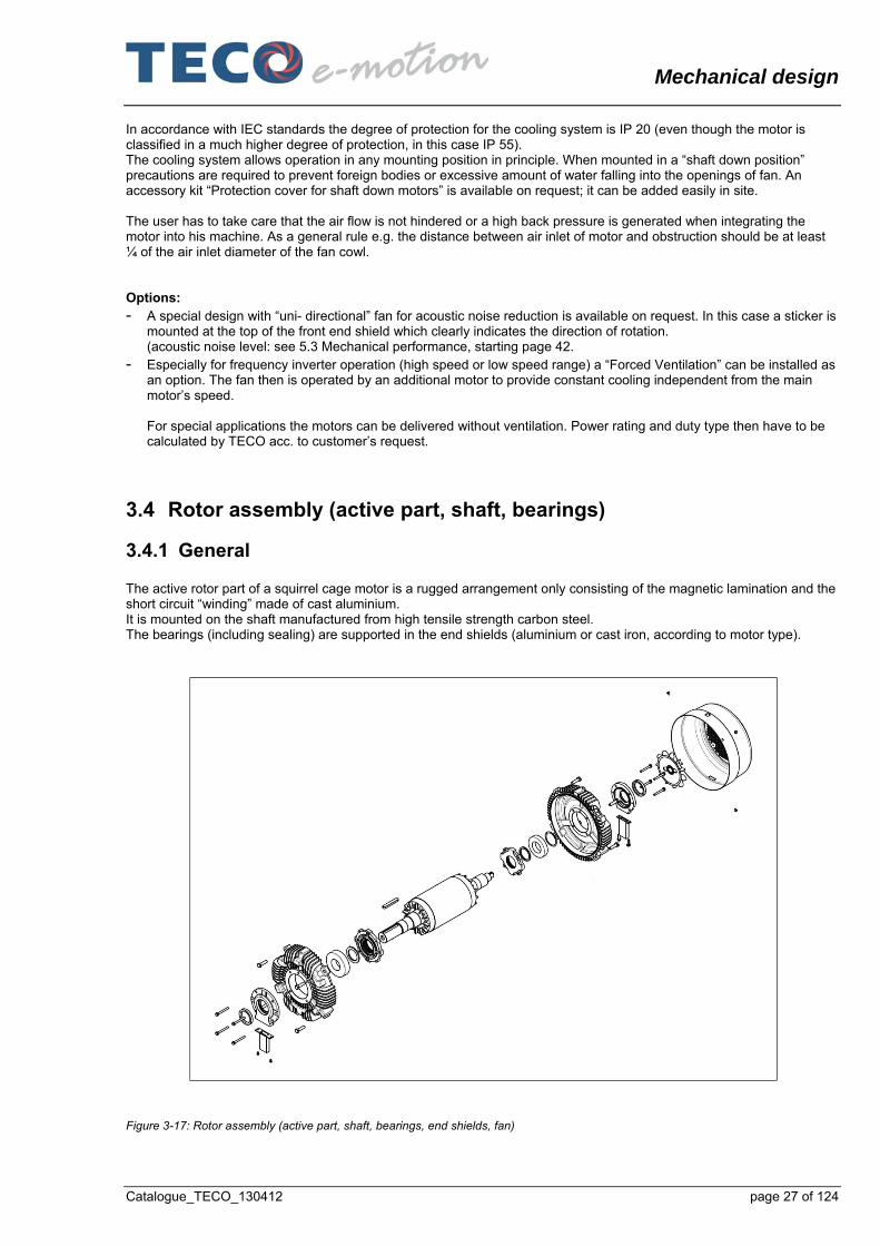
3.4.1 General The active rotor part of a squirrel cage motor is a rugged arrangement only consisting of the magnetic lamination and the short circuit “winding” made of cast aluminium. It is mounted on the shaft manufactured from high tensile strength carbon steel. The bearings (including sealing) are supported in the end shields (aluminium or cast iron, according to motor type).
Figure 3-17: Rotor assembly (active part, shaft, bearings, end shields, fan)

Mechanical design
page 28 of 124 Catalogue_TECO_130412
The rotor is dynamically balanced with half key and the shaft end face is marked according to standard DIN ISO 8821 (“H” = half key). The balance quality meets DIN ISO 1940, Q2,5. The mechanical vibrations of the motors meet level A according to EN 60034-14 at synchronous speed Mechanical vibrations; permissible axial and radial forces at DE and maximum mechanical speed: Se 5.3 Mechanical performance, starting page 42.
3.4.2 Shaft The dimensions of the DE shaft end (including the keyway) and their tolerances are standardized by IEC 60027-1 (DIN EN 50347). The DE shaft face has a threaded centre hole for mounting of customer’s shaft fitments. (Guidelines for proper coupling and alignment: see TECO manual “INSTALLATION, OPERATION and MAINTENANCE INSTRUCTIONS....” The key is press fit into key way. The NDE shaft end is carrying the fan; on larger machines (see dimensional diagrams. Depending on frame size its face is equipped with a threaded centre hole for later mounting of accessories (like speed sensor, etc.). The fan is manufactured from conductive polypropylene (non-sparking material).
3.4.3 Bearings As a standard both DE bearing and NDE bearing are ball bearings, suitable both for horizontal and vertical mounting of the motor (except for frame size 315, 2-pole; where a special bearing is provided for operation at vertical mounting, see tables below). As an option reinforced bearing types can be provided according to customer’s load specifications. The DE bearing is fixed; it absorbs axial and radial forces transmitted from the driven machine. The floating bearing is installed at the non drive end (NDE) to allow thermal expansion of the shaft and to absorb radial forces. The bearings are preloaded in axial direction by an undular washer at NDE. Even though the DE bearing is fixed due to a special design of the DE end shield it is easy to fit a flange end shield without removing the rotor. Disassembling of the rotor (e.g. for changing the terminal box position) can be carried out without disassembling the NDE). Motors up to frame size 160 are equipped with double shielded bearings (suffix “zz” on bearing type). Those motors bearings are lubricated for life. They are maintenance- free and cannot be regreased. Motors from frame size 180 up to frame size 315 are equipped with grease nipples both at DE and NDE for manual regreasing. These motors are already greased during manufacture. Grease nipples are of “flat button head” design according to DIN 3404 with thread M10x 1. DE and NDE nipple are easily accessible (NDE nipple outside of the fan cowl).
Figure 3-18: Regreasing sticker A shaft lock is fitted on frame size 280 and 315 to prevent bearing damage during transportation.

Mechanical design
Catalogue_TECO_130412 page 29 of 124
Tables with the types of standard bearings and reinforced bearings (optional):
Framesize
Poles Drive end Non drive end Remarks
2 6201 ZZC3 6201 ZZC3 Sealed bearings 63
4 6201 ZZC3 6201 ZZC3 Sealed bearings
2 6202 ZZC3 6202 ZZC3 Sealed bearings
4 6202 ZZC3 6202 ZZC3 Sealed bearings 71
6 6202 ZZC3 6202 ZZC3 Sealed bearings
2 6204 ZZC3 6204 ZZC3 Sealed bearings
4 6204 ZZC3 6204 ZZC3 Sealed bearings 80
6, 8 6204 ZZC3 6204 ZZC3 Sealed bearings
2 6205 ZZC3 6205 ZZC3 Sealed bearings
4 6205 ZZC3 6205 ZZC3 Sealed bearings 90
6, 8 6205 ZZC3 6205 ZZC3 Sealed bearings
2 6206 ZZC3 6305 ZZC3 Sealed bearings
4 6206 ZZC3 6305 ZZC3 Sealed bearings 100
6, 8 6206 ZZC3 6305 ZZC3 Sealed bearings
2 6306 ZZC3 6306 ZZC3 Sealed bearings
4 6306 ZZC3 6306 ZZC3 Sealed bearings 112
6, 8 6306 ZZC3 6306 ZZC3 Sealed bearings
2 6308 ZZC3 6308 ZZC3 Sealed bearings
4 6308 ZZC3 6308 ZZC3 Sealed bearings 132
6, 8 6308 ZZC3 6308 ZZC3 Sealed bearings
2 6309 ZZC3 6309 ZZC3 Sealed bearings
4 6309 ZZC3 6309 ZZC3 Sealed bearings 160
6, 8 6309 ZZC3 6309 ZZC3 Sealed bearings
Table 3-5: Standard bearings used in aluminium motors (type code: ALAA....)
Drive end Non drive end
Sealed Regreasable Sealed Regreasable
Standard Standard Standard Reinforced Standard Standard Frame size
Poles
All-mountings
B-mountings
V-mountings
All mountings
All-mountings
All-mountings
2 6204 ZZC3 nA nA nA 6204 ZZC3 nA
4 6204 ZZC3 nA nA nA 6204 ZZC3 nA 80
6, 8 6204 ZZC3 nA nA nA 6204 ZZC3 nA
2 6205 ZZC3 nA nA nA 6205 ZZC3 nA
4 6205 ZZC3 nA nA nA 6205 ZZC3 nA 90
6, 8 6205 ZZC3 nA nA nA 6205 ZZC3 nA
2 6206 ZZC3 nA nA nA 6206 ZZC3 nA
4 6206 ZZC3 nA nA nA 6206 ZZC3 nA 100
6, 8 6206 ZZC3 nA nA nA 6206 ZZC3 nA

Mechanical design
page 30 of 124 Catalogue_TECO_130412
Drive end Non drive end
Sealed Regreasable Sealed Regreasable
Standard Standard Standard Reinforced Standard Standard Frame size
Poles
All-mountings
B-mountings
V-mountings
All mountings
All-mountings
All-mountings
2 6306 ZZC3 nA nA nA 6306 ZZC3 nA
4 6306 ZZC3 nA nA nA 6306 ZZC3 nA 112
6, 8 6306 ZZC3 nA nA nA 6306 ZZC3 nA
2 6308 ZZC3 nA nA nA 6306 ZZC3 nA
4 6308 ZZC3 nA nA nA 6306 ZZC3 nA 132
6, 8 6308 ZZC3 nA nA nA 6306 ZZC3 nA
2 6309 ZZC3 nA nA nA 6307 ZZC3 nA
4 6309 ZZC3 nA nA nA 6307 ZZC3 nA 160
6, 8 6309 ZZC3 nA nA nA 6307 ZZC3 nA
Table 3-6: Standard bearings used in cast iron motors (type code: ALCA....), frame size up to 160
Drive end Non drive end
Sealed Regreasable Sealed Regreasable
Standard Standard Standard Reinforced Standard Standard Frame size
Poles
All-mountings
B-mountings
V-mountings
All mountings
All-mountings
All-mountings
2 nA 6311C3 6311C3 NU311 nA 6310C3
4 nA 6311C3 6311C3 NU311 nA 6310C3 180
6, 8 nA 6311C3 6311C3 NU311 nA 6310C3
2 nA 6312 C3 6312 C3 NU312 nA 6212 C3
4 nA 6312 C3 6312 C3 NU312 nA 6212 C3 200
6, 8 nA 6312 C3 6312 C3 NU312 nA 6212 C3
2 nA 6312 C3 6312 C3 NU312 nA 6212 C3
4 nA 6313 C3 6313 C3 NU313 nA 6213 C3 225
6, 8 nA 6313 C3 6313 C3 NU313 nA 6213 C3
2 nA 6313 C3 6313 C3 NU313 nA 6313 C3
4 nA 6315 C3 6315 C3 NU315 nA 6313 C3 250
6, 8 nA 6315 C3 6315 C3 NU315 nA 6313 C3
2 nA 6316 C3 6316 C3 NU316 nA 6314 C3
4 nA 6318 C3 6318 C3 NU318 nA 6316 C3 280
6, 8 nA 6318 C3 6318 C3 NU318 nA 6316 C3
2 nA 6316 C3 7316 C3 NU316 nA 6314 C3
4 nA 6320 C3 6320 C3 NU320 nA 6316 C3 315
6, 8 nA 6320 C3 6320 C3 NU320 nA 6316 C3
2 nA 6316 C3 7316 C3 NU316 nA 6316 C3
4 nA 6322 C3 6322 C3 NU322 nA 6322 C3 315D
6, 8 nA 6322 C3 6322 C3 NU322 nA 6322 C3
Table 3-7: Bearings used in cast iron motors (type code: ALCA....), frame size 180 up to 315

Mechanical design
Catalogue_TECO_130412 page 31 of 124
Bearing lifetime: The calculated operating life L10 of the bearings is at least 20000 hours, provided: - operation in horizontal position - operation at nominal max temperature and nominal speed - radial and axial forces are within the limits stated in the catalogue, ee 5.3 Mechanical performance, starting page 42. In case of operation with a coupling (no additional axial or radial forces from the driven machine) a lifetime of 50000 h is calculated. Lifetime is reduced when operated at increased ambient temperature higher speed than nominal or under severe vibration conditions. Tables for calculated operating lifetime:
Frame size
Lifetime at nominal operational conditions
2-pole 4-pole 6-pole 8-pole
[h] [h] [h] [h]
63 20000 40000 40000 40000
71 20000 40000 40000 40000
80 20000 40000 40000 40000
90 20000 40000 40000 40000
100 20000 40000 40000 40000
112 20000 40000 40000 40000
132 20000 40000 40000 40000
160 20000 40000 40000 40000
Table 3-8: Calculated lifetime for sealed standard bearings (operating life L10) Sealing: The sealing of DE and NDE bearing is provided by a radial seal ring with dust protection lip to fulfil the requirements of degree of protection “IP 55”. IP56 or IP65 protection options (dust tight; protection against powerful water jets) can be realized by reinforced sealing (see 3.4.3 Bearings, starting page 28). For applications with direct gearbox mounting an option “Oil Sealed Design” is available. Bearing insulation: If the motor is line operated (sinusoidal voltage supply) motors covered by this catalogue usually do not need a bearing insulation, because the shaft voltage (caused by small magnetic unbalance within the machine) does not exceed the level of 500 mV. This level is agreed as a save limit in the standard IEC 60034-17. If the motor is inverter operated, increased bearing stress by high frequent bearing currents might occur. As an option TECO recommends using insulated bearing on NDE for frame size 280 and above in this case (see 5.5 Motor performance (inverter operated), starting page 51).
Mechanical design
page 32 of 124 Catalogue_TECO_130412
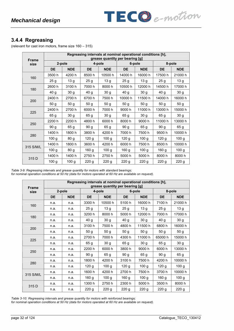
3.4.4 Regreasing (relevant for cast iron motors, frame size 160 – 315)
Regreasing intervals at nominal operational conditions [h], grease quantity per bearing [g]
2-pole 4-pole 6-pole 8-pole Frame size
DE NDE DE NDE DE NDE DE NDE
3500 h 4200 h 8500 h 10500 h 14000 h 16000 h 17500 h 21000 h 160
25 g 13 g 25 g 13 g 25 g 13 g 25 g 13 g
2600 h 3100 h 7000 h 8000 h 10500 h 12000 h 14500 h 17000 h 180
40 g 30 g 40 g 30 g 40 g 30 g 40 g 30 g
2400 h 2700 h 6700 h 7500 h 10000 h 11500 h 14000 h 16000 h 200
50 g 50 g 50 g 50 g 50 g 50 g 50 g 50 g
2400 h 2700 h 6000 h 7000 h 9000 h 11000 h 13000 h 15000 h 225
65 g 30 g 65 g 30 g 65 g 30 g 65 g 30 g
2200 h 2200 h 4800 h 6000 h 8000 h 9000 h 11000 h 13000 h 250
90 g 65 g 90 g 65 g 90 g 65 g 90 g 65 g
1400 h 1800 h 3800 h 4200 h 7000 h 7500 h 9500 h 10000 h 280
100 g 80 g 120 g 100 g 120 g 100 g 120 g 100 g
1400 h 1800 h 3600 h 4200 h 6000 h 7500 h 8500 h 10000 h 315 S/M/L
100 g 80 g 160 g 100 g 160 g 100 g 160 g 100 g
1400 h 1400 h 2750 h 2750 h 5000 h 5000 h 8000 h 8000 h 315 D
100 g 100 g 220 g 220 g 220 g 220 g 220 g 220 g
Table 3-9: Regreasing intervals and grease quantity for motors with standard bearings; for nominal operation conditions at 50 Hz (data for motors operated at 60 Hz are available on request).
Regreasing intervals at nominal operational conditions [h], grease quantity per bearing [g]
2-pole 4-pole 6-pole 8-pole Frame size
DE NDE DE NDE DE NDE DE NDE
n.a. n.a. 3300 h 10500 h 5100 h 16000 h 7100 h 21000 h 160
n.a. n.a. 25 g 13 g 25 g 13 g 25 g 13 g
n.a. n.a. 3200 h 8000 h 5000 h 12000 h 7000 h 17000 h 180
n.a. n.a. 40 g 30 g 40 g 30 g 40 g 30 g
n.a. n.a. 3100 h 7500 h 4800 h 11500 h 6800 h 16000 h 200
n.a. n.a. 50 g 50 g 50 g 50 g 50 g 50 g
n.a. n.a. 2700 h 7000 h 4300 h 11000 h 65000 h 15000 h 225
n.a. n.a. 65 g 30 g 65 g 30 g 65 g 30 g
n.a. n.a. 2200 h 6000 h 3800 h 9000 h 6000 h 13000 h 250
n.a. n.a. 90 g 65 g 90 g 65 g 90 g 65 g
n.a. n.a. 1800 h 4200 h 3100 h 7500 h 4200 h 10000 h 280
n.a. n.a. 120 g 100 g 120 g 100 g 120 g 100 g
n.a. n.a. 1600 h 4200 h 2700 h 7500 h 3700 h 10000 h 315 S/M/L
n.a. n.a. 160 g 100 g 160 g 100 g 160 g 100 g
n.a. n.a. 1300 h 2750 h 2300 h 5000 h 3500 h 8000 h 315 D
n.a. n.a. 220 g 220 g 220 g 220 g 220 g 220 g
Table 3-10: Regreasing intervals and grease quantity for motors with reinforced bearings; for nominal operation conditions at 50 Hz (data for motors operated at 60 Hz are available on request).

Mechanical design
Catalogue_TECO_130412 page 33 of 124
The grease must be replaced at regular intervals depending on the motor size and its usage. The used grease exits through a grease drain. Regreasing intervals and grease quantity: see tables Table 3-9 and Table 3-10 and regreasing labels on the motor. Regard that greasing intervals are given for operation at rated speed, nominal operation conditions and for horizontal mounting position. In case of vertical use the intervals shall be reduced to 50%. In case of ambient temperature higher than 40°C or when operated with higher speed than nominal the intervals have to be reduced according table below:
Ambient temperature + 40°C + 50°C + 60°C
Recommended reduction of regreasing intervals
1 0,6 0,4
continuous speed nominal 1,5 x
nominal 2 x
nominal
Recommended reduction of regreasing intervals
1 0,6 0,5
Table 3-11: Rule of thumb for reduction of regreasing intervals Details (grease type, recommendations for greasing procedure) can be seen on additional regreasing nameplates (close to the regreasing nipples) and the TECO manual “INSTALLATION, OPERATION and MAINTENANCE INSTRUCTIONS”.
3.5 Degree of protection The IEC classification system IEC60034- 5 defines the protection against external influence, e.g. degree “IP 55”. The first numeral describes the protection of people against contact with live parts and rotating parts and the protection against ingress of dust. The second numeral defines the protection against ingress of water. As a standard the motors comply with degree IP 55; this describes: - The machine is completely protected against contact with live or rotating parts. Ingress of dust is not totally
prevented, but dust does not enter in sufficient quantity to interfere with satisfactory operation of the machine. - The machine is protected against water jets. Water projected by a nozzle against the machine from any direction has
no harmful effect. (Remark: Restrictions concerning fan, degree IP 20, and the shaft end are covered by standards). This allows the operation of the motor in a rough environment. In outdoor application the motor shall be protected against excessive solar radiation. The motors are intended for use in a “Safe Area”. Operation in “Hazardous Area” is not permitted.
Opionally IP 56 or IP 66 (dust tight; protection against powerful water jets) can be realized by reinforced sealing (see 3.4.3 Bearings, starting page 28).

Mechanical design
page 34 of 124 Catalogue_TECO_130412
3.6 Others
3.6.1 Grounding terminals The grounding terminals are directly screwed into the motor frame and have no other function except of grounding, they comply with .EN 60 204-1. Screws, washers and U-clamps are made of electro-zinc plated steel. They are labelled with the ground symbol defined in DIN EN 60 617-2: One terminal is located inside of the terminal box. The stator housing provides 4 external access points for grounding to allow easy access in every possible mounting position. The assembled grounding access point shall be free of primer or paint and shall be metallic blank. Only 1 access points is finally assembled ex factory (right hand side). Design examples for grounding terminals: a) for motors frame size 80 … 250 b) for motors frame size 280 and larger
Figure 3-19: Design examples for grounding terminals
3.6.2 Lifting eyes Using the lifting eye(s) is obligatory when transporting and lifting the motor; details see TECO manual “INSTALLATION, OPERATION and MAINTENANCE INSTRUCTIONS ....”. The position of the lifting eye(s) can be seen in the sample figure below and in section 7 Outline drawings, starting page 82. In case of 2 lifting eyes (frame size 132 and larger) both of the 2 lifting eyes have to be used. They are located in a way that there is no collision with already installed power cables installed in axial direction.

Mechanical design
Catalogue_TECO_130412 page 35 of 124
Figure 3-20: Position of lifting eyes
3.6.3 Drain holes As a standard no drain holes are provided. Drain holes can be drilled on customer’s request for frame size 132 and larger. They will be located in the brackets or flanges and not in the housing to allow later modifications of the mounting arrangement.
3.6.4 SPM provision Drilled, tapped and plugged holes with conical M8 thread for later shock pulse measurement nipple mounting on DE and NDE are provided for frame size 280 and above.
3.6.5 Painting, corrosion protection Concerning corrosion the top coat is resistant to water, steam and salt water. Concerning chemical surrounding the top coat is resistant to hydraulic liquids, cleaning agents, synthetic coolants, solvents and chemicals. The coating is appropriate for a temperature range from -40°C to +130°C; it stays nonabrasive, elastic, scratch resistant and impact resistant through the whole temperature range. The motors are suitable for use in paint shops and are 100% free of paint adhesion detrimental substances as for example silicone. Layer thickness see figure below.
Cast iron, frame size ≤ 132 Aluminium motors ≤ 160
Cast iron, frame size ≥ 160
Primer for cast iron parts min. 20 µm min. 25 µm
Primer for aluminium parts min. 20 µm -
Primer for steel parts min. 20µm min. 25 µm
Base prior to top coat min. 20 µm min. 50 µm
Top coat * min. 20 µm min. 25 µm
Total thickness of coating min. 60 µm min. 100 µm
*) The inner surface of the fan cowl is treated with primer only
Table 3-12: Layer thickness of painting

Mechanical design
page 36 of 124 Catalogue_TECO_130412
As a standard the motor frame and fan cowl colour is grey (RAL 7032, pebble grey). For later customizing of the motor it is possible to spray a second layer of top coat (same thickness as standard coating) without influence to the thermal design of the motor. All machined and metallic blank surfaces (feet, flange, 1 external grounding surface, shaft end) are protected against corrosion. The antirust agent can stay at the parts without influence to customer assembling (coupling) or mounting the motor to machine (max. layer thickness 5 µm).
3.6.6 Rating plate and labelling The material of the rating plate is stainless steel and the data indicated are irremovable and clearly engraved or lasered. It is irremovably fixed (riveted) at the motor frame. Rating plate data comply with IEC 60 034-1 and contain e.g. (see sample below): - name of manufacturer - serial number (a unique individual identification number) and year of construction - reference to IEC standard - efficiency level (efficiency class IE-code according to IEC 60 034-30) - the CE marking - technical data according to IEC 60 034-1. The Rating plate is split into 2 sections, mounted on a common plastic base plate. The plastic base plate and the main section (bottom) of the rating plate are riveted to the motor frame. The upper section is solely wearing the manufacturer’s brand and is clipped into the plastic base plate. As a standard it will carry the TECO-Brand; optionally with customer’s brand instead. For original equipment manufacturers it is possible to remove the original brand plate easily and to clip an individual brand plate into the plastic base plate in site.
Figure 3-21: Sample of a TECO rating plate Additional nameplates and markings: - Connection diagram sticker with the wiring diagram, fitted on the inside of the terminal box lid - In case of optional accessories: connection diagram sticker inside terminal box - Grounding symbols according to DIN EN 60617-2 - Incase of regreasable bearings: regreasing nameplates (close to the regreasing nipples)

Electrical design
Catalogue_TECO_130412 page 37 of 124
4 Electrical design Squirrel cage motors as covered by this catalogue provide electrical active parts: - Rotor
The active part is a rugged arrangement only consisting of the magnetic lamination and the short circuit “winding” made of cast aluminium embedded in slots.
- Stator Contains the magnetic stator lamination, the three phase winding embedded in slots; including its insulation system and integrated temperature sensors.
- Terminals
4.1 Stator winding The stator winding is carried out as a wire wound winding (“random winding”). High quality enamelled wires are used. Insulating sheets provide proper performance for - insulation phase to ground, - insulation phase to phase and - interturn insulation. An appropriate phase separation and a proper bandage of the winding overhang ensure high electric and mechanical strength. The stator winding is rotating dip impregnated with varnish or resin according to “thermal class F” requirements. According to the classification EN 60085 thermal class F allows a maximum hot spot temperature of 155°C. TECO motors covered by this catalogue are utilized (under nominal conditions) according to class “B”: - average temperature rise (by resistance method) is 80°K; - maximum spot temperature is 130°C. This ensures a high lifetime of the insulation system. (Insulation does not suddenly fail if the maximum temperature of the thermal class is reached, but useful operating life declines rapidly. A rule of thumb is a halving of life time for every increase of 10°C.) As an option an additional finish for tropical protection (against fungus) can be provided (option “Tropical Climate Proof”).
Figure 4-1: Stator core with slot liners Figure 4-2: Stator core with winding
Electrical design
page 38 of 124 Catalogue_TECO_130412
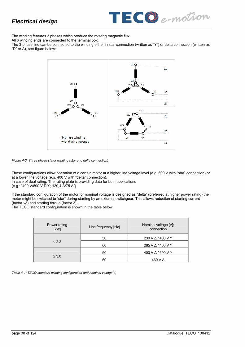
The winding features 3 phases which produce the rotating magnetic flux. All 6 winding ends are connected to the terminal box. The 3-phase line can be connected to the winding either in star connection (written as “Y”) or delta connection (written as “D” or ∆), see figure below:
Figure 4-3: Three phase stator winding (star and delta connection) These configurations allow operation of a certain motor at a higher line voltage level (e.g. 690 V with “star” connection) or at a lower line voltage (e.g. 400 V with “delta” connection). In case of dual rating: The rating plate is providing data for both applications (e.g.: “400 V/690 V D/Y; 129,4 A/75 A”). If the standard configuration of the motor for nominal voltage is designed as “delta” (preferred at higher power rating) the motor might be switched to “star” during starting by an external switchgear. This allows reduction of starting current (factor √3) and starting torque (factor 3). The TECO standard configuration is shown in the table below:
Power rating [kW]
Line frequency [Hz] Nominal voltage [V];
connection
50 230 V ∆ / 400 V Y 2.2
60 265 V ∆ / 460 V Y
50 400 V ∆ / 690 V Y 3.0
60 460 V ∆ Table 4-1: TECO standard winding configuration and nominal voltage(s)

Electrical design
Catalogue_TECO_130412 page 39 of 124
The configuration can be carried out by the user by inserting the jumpers of the terminal box; the spatial arrangement is shown in the figure below (standard sticker inside of the terminal box):
Figure 4-4: Arrangement of connection bolts and jumpers for star/delta connection Phase sequence: If the terminals are connected to an electrically clockwise supply system the motor is designed for clockwise mechanical rotation (when viewing from driving shaft end; according to IEC 60 034-8). For change of rotational direction a change of 2 supply line phases has to be carried out by customer.
4.2 Thermal protection For thermal protection of the winding as a standard 3 temperature PTC thermistors are embedded in the winding; one for each phase (acc to standards IEC 60 034-11 and DIN 44081). Their nominal temperature level is 150°C; when reaching this temperature their resistance suddenly escalates to a high level. They are connected in series and lead to terminals in the terminal box. A suitable monitoring device according to standard DIN 44081 shall be connected by customer and shall be used for tripping the system. At inverter operation the use of this method of thermal protection is mandatory; protection measures based on operating current are not suitable in this case. A warning on the sticker inside the terminal box shows that no voltage higher than 2,5 V must be applied on these terminals.

Performance data
page 40 of 124 Catalogue_TECO_130412
5 Performance data
5.1 Duty type The motors are designed for continuous operation at full load under nominal ambient conditions (duty type “S1” according to IEC 60034-1. Type data for differing duty types (S2 ... S8, periodic variation of load, influence of frequent starting stress, etc.) and S9 (non-periodic load and speed variation, e.g. at inverter operation) can be evaluated on request.
5.2 Environmental conditions, performance All environmental conditions in site as listed in standard IEC 60721-3 (temperature, altitude, exposition to water, biological, chemical and mechanical active substances, vibrations, etc. have to be in accordance with the design of the motor (e.g. degree of protection).
5.2.1 Operation at high ambient temperature /high altitude As a standard the motors are designed for - ambient temperature (cooling air temperature): -20°C up to + 40°C - maximum altitude 1000 m above sea level The motors can also be operated at higher ambient temperatures or at higher altitude if the continuous output power is reduced, see figures below. In this case the winding temperature rise is approximately identical to nominal operation. It has to be regarded that the bearing stress at higher temperature is increased and regreasing intervals shall be shortened accordingly then (see 3.4.3 Bearings, starting page 28).
75
80
85
90
95
100
1000 1500 2000 2500 3000
%
altitude [m]
output power versus altitude
Figure 5-1: Reduction of output power versus ambient temperature

Performance data
Catalogue_TECO_130412 page 41 of 124
75
80
85
90
95
100
1000 1500 2000 2500 3000
%
altitude [m]
output power versus altitude
Figure 5-2: Reduction of output power versus altitude Output with nominal power rating is permissible at high altitude, if accordingly the ambient temperature is reduced, see figure below:
15
20
25
30
35
40
1000 1500 2000 2500 3000
°C
altitude [m]
ambient temperature versus altitude
Figure 5-3: Reduction of ambient temperature versus altitude for nominal output rating
5.2.2 Operation at low temperature /high humidity For operation at ambient temperature range -20 °C to -40 °C a heater for the motor winding is necessary at standstill. The same precaution is requested for operation in sites with normal temperature level, but high humidity (typically above 90%) to prevent condensation inside the motor. Heating can be carried out: - By accessory “Heating via strip heater”
In this case additional terminals for the heater are provided within the terminal box. Heater terminals are marked with a voltage flash and a short note “Heater may be energized even if motor is isolated!” A special connection diagram sticker with the wiring diagram of the accessory is fitted inside terminal box lid. Approx. heater power see Table 5-1, page 42.
- By heating the motor via stator winding. An auxiliary single phase AC voltage supply is to be connected to 2 power connectors. The appropriate voltage level and VA- rating depending on the motor size: On request.
The safety precautions as mentioned above have to be regarded by the user.

Performance data
page 42 of 124 Catalogue_TECO_130412
To prevent condensation For ambient temperature -20°C to - 40°C
Frame size
Heater output
[W]
Heater nominal voltage single phase AC [V]
Heater output
[W]
Heater nominal voltage single phase AC [V]
230 400 230 400
63 10 10 10 10 10 10
71 10 10 10 10 10 10
80 20 20 20 20 20 20
90 20 20 20 20 20 20
100 30 30 30 30 30 30
112 30 30 30 30 30 30
132 40 40 40 40 40 40
160 40 40 40 40 40 40
180 50 50 50 50 50 50
200 50 50 50 50 50 50
225 60 60 60 60 60 60
250 60 60 60 60 60 60
280 150 150 150 150 150 150
315 200 200 200 200 200 200
Table 5-1: Availability and output power of option “Heating via Strip Heater”
5.2.3 Operation at severe mechanical conditions For operation at extraordinary mechanical conditions (permanent exposure to vibration and shock higher than class 3M3 acc. to IEC 60721-3) we recommend a special request.
5.3 Mechanical performance
5.3.1 Torque characteristic; starting performance The power rating (nominal power PN) and the nominal torque (TN) of each type is listed in 6 Technical data, starting page 58. The torque can be calculated in general as:
9550 x P T =
n where T = torque [Nm] P = power [kW] and n = speed [rpm]. The motors are equipped with a squirrel cage rotor (cast aluminium); they are suitable for direct starting. Direction of rotation is clockwise (view onto shaft end) if a clockwise supply system is connected according to the wiring diagram. Technical data of the standard motors are valid for both directions of rotation (bidirectional design). In IEC 600034-12 the starting performance is standardized.

Performance data
Catalogue_TECO_130412 page 43 of 124
During starting the motor creates a torque according to its individual characteristic (locked rotor torque, pull up torque and break down torque as generally described in 1.2.7 Performance characteristics: Speed, torque, starting page 11). Depending on the type an individual value for the torques is listed in 6 Technical data, starting page 58. A sample of a TECO type test see figure below. In steady operation at full load torque the individual nominal speed (close to no load speed) is reached. It has to be regarded that this speed is only valid for thermal equilibrium conditions. If the motor is not heated up this speed will be significant closer to the no load speed. Limits and tolerances according to IEC standard: see 6.1 General data; tolerances (acc. to IEC 60034-1), starting page 58. According to requirements of IEC 60034 the break down torque (including -10% tolerance) has to be 160 % at least. The torque values are quadratic depending on a variation of line voltage. (Correspondingly the complete torque characteristic e.g. is reduced by a factor of 3 when starting the motor in star-delta).
Figure 5-4: Sample of TECO type test data sheet: Torque and current vs. speed
5.3.2 Maximum operational speed It is possible to increase the speed e.g. by feeding the motor from a frequency inverter with increased frequency. In general it shall be regarded at increased speed (also see 5.5 Motor performance (inverter operated), starting page 51): - increase of acoustic noise level (especially contribution of fan noise) - increase of vibration - regreasing intervals shall be shortened accordingly then (see 3.4.3 Bearings, starting page 28) - bearing life may be reduced - maximal mechanically permissible operational speed limit,
see table below, following the requirements of IEC 60034-1; both for horizontal and vertical mounting:

Performance data
page 44 of 124 Catalogue_TECO_130412
2-pole 4-pole 6-pole 8-pole Frame
size [min-1] [Hz] [min-1] [Hz] [min-1] [Hz] [min-1] [Hz] 63 5200 87 3600 120 2400 120 1600 106 71 5200 87 3600 120 2400 120 1600 106 80 5200 87 3600 120 2400 120 1600 106 90 5200 87 3600 120 2400 120 1600 106 100 5200 87 3600 120 2400 120 1600 106 112 5200 87 3600 120 2400 120 1600 106 132 4500 75 2700 90 2400 120 1600 106 160 4500 75 2700 90 2400 120 1600 106 180 4500 75 2700 90 2400 120 1600 106 200 4500 75 2300 77 1800 90 1200 80 225 3600 60 2300 77 1800 90 1200 80 250 3600 60 2300 77 1800 90 1200 80 280 - - - - - - - - 315 - - - - - - -
Table 5-2: Maximal permissible operational speed
5.3.3 Permissible radial shaft forces At operation with belt drive (or caused by other influences of the driven equipment) radial forces will impact on shaft end and bearings. For belt drives a rough estimation of the radial force can be carried out:
5000 x P Fr
D x n where Fr =radial force [N] P = power rating [kW] D = diameter of pulley [m] and n = speed [rpm]. The permissible radial force depends on the axial point of application of the external force, see figure below:
Figure 5-5: Axial point of application of the external radial force

Performance data
Catalogue_TECO_130412 page 45 of 124
The permissible radial thrust is given in the table below: - for standard ball bearings and - for optional version with cylinder roller bearings. It has to be regarded that cylinder roller bearings demand a minimum radial force for proper operation.
Radial bearing load FR [N]
Load FR for standard ball bearings Load FR for cylinder roller bearings
Aluminium motors Cast iron motors Cast iron motors
Max. Max. Max. Max. Max. Max. Max. Max. Max. Min.
Frame size
poles FR1 FR2 FR3 FR1 FR2 FR3 FR1 FR2 FR3 FR3 min
2 n.a. n.a. n.a. n.a. n.a. n.a. n.a. 4 n.a. n.a. n.a. n.a. n.a. n.a. n.a. 6 n.a. n.a. n.a. n.a. n.a. n.a. n.a.
63
8 n.a. n.a. n.a. n.a. n.a. n.a. n.a. 2 n.a. n.a. n.a. n.a. n.a. n.a. n.a. 4 n.a. n.a. n.a. n.a. n.a. n.a. n.a. 6 n.a. n.a. n.a. n.a. n.a. n.a. n.a.
71
8 n.a. n.a. n.a. n.a. n.a. n.a. n.a. 2 558 620 682 n.a. n.a. n.a. n.a. 4 699 777 855 n.a. n.a. n.a. n.a. 6 n.a. n.a. n.a. n.a.
80
8 n.a. n.a. n.a. n.a. 2 583 659 736 n.a. n.a. n.a. n.a. 4 741 838 936 n.a. n.a. n.a. n.a. 6 849 961 1073 n.a. n.a. n.a. n.a.
90
8 n.a. n.a. n.a. n.a. 2 830 932 1034 n.a. n.a. n.a. n.a. 4 1039 1168 1296 n.a. n.a. n.a. n.a. 6 1186 1333 1479 n.a. n.a. n.a. n.a.
100
8 n.a. n.a. n.a. n.a. 2 1157 1293 1429 n.a. n.a. n.a. n.a. 4 1465 1637 1809 n.a. n.a. n.a. n.a. 6 1699 1898 2098 n.a. n.a. n.a. n.a.
112
8 n.a. n.a. n.a. n.a. 2 1734 1970 2207 n.a. n.a. n.a. n.a. 4 2185 2428 2780 n.a. n.a. n.a. n.a. 6 2530 2834 3139 n.a. n.a. n.a. n.a.
132
8 n.a. n.a. n.a. n.a. 2 2198 2507 2816 4 2740 3125 3511 6 3143 3541 3938
160
8 2 n.a. n.a. n.a. 3141 3529 3917 6669 7407 8327 919 4 n.a. n.a. n.a. 3835 4316 4796 8027 8920 10036 804 6 n.a. n.a. n.a. 4398 4902 5405 9186 10135 11302 766
180
8 n.a. n.a. n.a. 2 n.a. n.a. n.a. 3434 3793 4152 7350 8119 8888 1108 4 n.a. n.a. n.a. 4368 4825 5282 9075 10024 10973 960 6 n.a. n.a. n.a. 4965 5485 6004 10203 11271 12338 911
200
8 n.a. n.a. n.a. 2 n.a. n.a. n.a. 4010 4401 4792 8233 9036 9839 1316 4 n.a. n.a. n.a. 4731 5346 5962 9503 10739 11976 1131 6 n.a. n.a. n.a. 5436 6112 6788 10817 12161 13506 1069
225
8 n.a. n.a. n.a. 2 n.a. n.a. n.a. 4902 5441 5981 11585 12860 14135 1807 4 n.a. n.a. n.a. 6026 6685 7343 14149 15695 17240 1525 6 n.a. n.a. n.a. 7130 7909 8688 16194 17963 19732 1431
250
8 n.a. n.a. n.a. 2 n.a. n.a. n.a. 5231 5685 6224 11638 12656 13856 2092 4 n.a. n.a. n.a. 7482 8255 9210 17635 19451 21692 2241 6 n.a. n.a. n.a. 8353 9210 10275 19671 21705 24216 2082
280
8 n.a. n.a. n.a. 2 n.a. n.a. n.a. 5208 5514 5871 12114 12827 13642 2094 4 n.a. n.a. n.a. 8895 9786 10894 22106 24348 27100 2910 6 n.a. n.a. n.a. 24996 27531 30640 2679
315 L
8 n.a. n.a. n.a.
Table 5-3: Permissible radial shaft forces

Performance data
page 46 of 124 Catalogue_TECO_130412
5.3.4 Permissible axial shaft forces The permissible external forces in axial direction (direction towards DE or towards NDE) is depending on the mounting position of the motor: - horizontal shaft, - shaft up or - shaft down. The figures refer to standard bearing design (reinforced version on request) and operation at nominal speed or horizontal mounting; e. g. mounting B3, B5, B6, B7, B8, B14, B34, B35:
Fa >> DE Fa >> NDE
Figure 5-6: Mounting position “horizontal” and directions of axial force
Maximal axial bearing load Fa [N]
Frame size
2-pole 4-pole 6-pole 8-pole
Fa >> NDE Fa >> DE Fa >> NDE Fa >> DE Fa >> NDE Fa >> DE Fa >> NDE Fa >> DE
← → ← → ← → ← →
63
71
80 490 490 617 617
90 470 470 676 676 774 774
100 657 657 931 931 1068 1068
112 911 911 1294 1294 1490 1490
132 1401 1401 1960 1960 2254 2254
160 1793 1793 2528 2528 2881 2881
180 2470 2470 3440 3440 3920 3920
200 2734 2734 3459 3459 4449 4449
225 3165 3165 3920 3920 5018 5018
250 3900 3900 4753 4753 6233 6233
280 4106 4106 6085 6085 6860 6860
315 S/M 3775 3775 6694 6694 7577 7577
315 L 3645 3645 6713 6713 7693 7693
Table 5-4: Maximal permissible axial bearing load for mounting position “horizontal”

Performance data
Catalogue_TECO_130412 page 47 of 124
5.3.5 Vibration The motors are dynamically balanced with half key and the shaft end face is marked according to standard DIN ISO 8821 (marking “H” = half key). The balance quality meets DIN ISO 1940, Q2,5. The mechanical vibrations of the motors meet level A according to EN 60034-14 at synchronous speed; standardized limits see table below (special design like full-key-balancing, no-key-balancing or vibration grade B on request.)
Frame size 56 to 132 160 to 280 > 280
Displac. Veloc. Displac. Veloc. Displac. Veloc.
Mounting [µm] [mm/s] RMS
[µm] [mm/s] RMS
[µm] [mm/s] RMS
Free suspension
25 1,6 35 2,2 45 2,8 Vibration Grade A Rigid
mounting 21 1,3 29 1,8 37 2,3
Free suspension
11 0,7 18 1,1 29 1,8 Vibration Grade B Rigid
mounting n.a. n.a. 14 0,9 24 1,5
Grade “A” applies to machines with no special vibration requirements; Grade “B” applies to machines with special vibration requirements.
Table 5-5: Vibration limits according to IEC 60034-14
5.4 Motor performance (line operated) The motors covered by this catalogue are low voltage asynchronous motors; designed for operation at a three phase AC voltage system (depending on the type; availability see 4.1 Stator winding, starting page 37): - 230 V, 3 AC, 50 Hz, - 400 V, 3 AC, 50 Hz, - 690 V, 3 AC, 50 Hz, according to IEC 60038 and - 265 V, 3 AC, 60 Hz, - 460 V, 3 AC, 60 Hz. The motors are designed for efficiency class IE2 (aluminium motors) and for both IE2 and IE3 (cast iron motors).

Performance data
page 48 of 124 Catalogue_TECO_130412
5.4.1 Requirements for supply voltage and frequency Permissible tolerances of voltage and frequency at operation IEC 60034-1 defines 2 ranges of permissible variation of voltage and frequency, “Zone A” and “Zone B”, see figure below:
Zone A
Nominal point
Zone B
voltage
frequency
Figure 5-7: Permissible tolerance of voltage and frequency acc. to IEC 60034-1 “Zone A”: According to IEC 60034-1 the motor is suitable to perform its nominal torque continuously. The performance characteristics may have deviations from the nominal values and the temperature rise is higher than nominal. “Zone B”: (continuous operation is explicitly not recommended by IEC 60034-1): The motor is suitable to perform its nominal torque continuously. The performance characteristics may have greater deviations from the nominal values; the temperature rise is higher than within “Zone A”. Requirements for waveform and unbalance of the supply voltage: Distortion of the sinusoidal waveform (caused by neighbouring power electronics) and unbalance of the voltage system (e.g. caused by single-phase loads) is permissible within the limits given in IEC 60034-1 section 7.2.1.1 (distortion factor HVF < 3% and negative sequence component < 1%). Special requirements (voltage peaks) have to be observed at inverter operation: see 5.5 Motor performance (inverter operated), starting page 51.
5.4.2 Current, power factor and efficiency at partial load The general characteristic is shown in section 1 (e.g. Figure 1-4, page 13). Type specific data for TECO motors: - Values for the nominal point can be seen on the rating plate and in 6 Technical data, starting page 58. - Values for partial load (power factor and efficiency) can be seen in 6 Technical data, starting page 58,
columns 1/4, 2/4 and 3/4 partial load. Overload capability according to IEC 60034-1 section 9: 150 % of nominal current during 2 min. at least; Min. 160 % of full load torque for 15 sec.

Performance data
Catalogue_TECO_130412 page 49 of 124
5.4.3 Current during starting, limitations General characteristic: see 1.2 Basics, terms and definitions, starting page 9 (sample for a TECO type test protocol: see Figure 5-4, page 43). Type specific data for TECO motors are evaluated during type test and are available on request. Overload capability: A minimum of overload capability is defined in IEC 60034-1 section 9: - Min. 2 min. at 150 % of nominal current (for motors with power rating up to 315 kW); - Min. 160 % of full load torque for 15 sec. Locked rotor: The motors are suitable for direct starting; however the high current during starting causes a high thermal load for the stator winding and especially for the rotor. A maximum locked rotor time has to be regarded, depending on the type. The table below shows the max. duration when starting at cold machine and at nominal operation temperature:
Maximum locked rotor time [s]: 50 Hz; cast iron; IE2 version (n.a. = not available)
2-pole 4-pole 6-pole 8-pole Nominal power [kW] Cold Hot Cold Hot Cold Hot Cold Hot
0,18 n.a. n.a. n.a. n.a. n.a. n.a. 102,9 51,4
0,25 n.a. n.a. n.a. n.a. n.a. n.a. 95,2 47,6
0,37 n.a. n.a. n.a. n.a. 53,3 26,7 116,9 58,4
0,55 n.a. n.a. 39,2 19,6 73,0 36,5 82,0 41,0
0,75 17,3 8,6 37,4 18,7 61,9 30,9 57,0 28,5
1,1 11,1 5,6 30,4 15,2 47,4 23,7 52,8 26,4
1,5 10,8 5,4 25,9 13,0 45,9 23,0 41,5 20,8
2,2 10,2 5,1 23,3 11,7 29,5 14,7 23,1 11,6
3 10,1 5,0 20,9 10,5 28,9 14,5 20,8 10,4
4 16,6 8,3 14,4 7,2 25,2 12,6 40,2 20,1
5,5 10,5 5,3 17,8 8,9 22,9 11,5 32,0 16,0
7,5 10,2 5,1 11,4 5,7 19,3 9,7 32,7 16,4
11 18,5 9,2 15,9 7,9 17,4 8,7 25,4 12,7
15 14,1 7,0 12,3 6,2 24,1 12,1 31,2 15,6
18,5 15 7,5 37,1 18,5 31,9 15,9 51,8 25,9
22 18,8 9,4 29,9 14,9 31,7 15,8 53,4 26,7
30 22,0 11,0 17,2 8,6 34,3 17,1 41,6 20,8
37 18,9 9,5 26,3 13,1 38,6 19,3 30,9 22,1
45 20,4 10,2 21,3 10,7 19,7 14,1 27,7 19,8
55 24,9 12,4 19,9 9,9 19,9 14,2 20,6 14,7
75 13,4 9,6 10,4 7,4 18,2 13,0 19,0 13,6
90 11,9 8,5 8,5 6,1 15,5 11,1 18,3 13,1
110 14,0 10,0 10,5 7,5 16,2 11,6 17,9 12,8
132 12,9 9,2 9,1 6,5 16,1 11,5 14,1 10,1

Performance data
page 50 of 124 Catalogue_TECO_130412
Maximum locked rotor time [s]: 50 Hz; cast iron; IE2 version (n.a. = not available)
2-pole 4-pole 6-pole 8-pole Nominal power [kW] Cold Hot Cold Hot Cold Hot Cold Hot
160 10,2 7,3 9,7 6,9 12,3 8,8 13,9 9,9
200 9,4 6,7 8,5 6,1 12,2 8,7 13,2 9,4
250 9,9 7,1 9,9 7,1 10,8 7,7 12,2 8,7
315 9,1 6,5 8,1 5,8 14,6 10,4 n.a. n.a.
Maximum locked rotor time [s]: 60 Hz; cast iron; IE2 version (n.a. = not available)
2-pole 4-pole 6-pole 8-pole Nominal power [kW] Cold Hot Cold Hot Cold Hot Cold Hot
0,18 n.a. n.a. n.a. n.a. n.a. n.a. 102,9 51,4
0,25 n.a. n.a. n.a. n.a. n.a. n.a. 95,2 47,6
0,37 n.a. n.a. n.a. n.a. 53,0 26,5 116,9 58,4
0,55 n.a. n.a. 38,2 19,1 66,7 33,4 82,0 41,0
0,75 14,4 7,2 34,8 17,4 58,4 29,2 57,0 28,5
1,1 10,8 5,4 27,7 13,8 44,8 22,4 52,8 26,4
1,5 10,0 5,0 23,7 11,8 39,6 19,8 41,5 20,8
2,2 10,4 5,2 20,5 10,3 23,7 11,9 23,1 11,6
3 10,1 5,0 16,8 8,4 23,0 11,5 20,8 10,4
4 13,7 6,8 15,5 7,7 20,0 10,0 42,5 21,3
5,5 11,2 5,6 23,9 12,0 17,1 8,6 33,0 16,5
7,5 10,1 5,1 10,5 5,3 18,4 9,2 34,4 17,2
11 17,8 8,9 16,5 8,2 16,4 8,2 24,5 12,2
15 14,5 7,2 16,2 8,1 22,7 11,4 24,8 12,4
18,5 16,4 8,2 25,7 12,9 24,9 12,4 47,8 23,9
22 16,6 8,3 22,8 11,4 24,6 12,3 50,2 25,1
30 16,7 8,4 16,4 8,2 30,3 15,1 29,2 14,6
37 16,5 8,2 22,9 11,5 27,4 13,7 33,9 24,2
45 16,4 8,2 16,7 8,4 26,2 18,7 33,2 23,7
55 21,8 10,9 16,8 8,4 24,5 17,5 24,5 17,5
75 16,7 11,9 15,5 11,1 20,3 14,5 23,9 17,1
90 14,1 10,1 12,7 9,1 17,4 12,4 15,5 11,1
110 17,9 12,8 11,8 8,4 16,8 12,0 15,1 10,8
132 13,7 9,8 10,5 7,5 24,5 17,5 23,9 17,1
160 11,6 8,3 8,4 6,0 17,8 12,7 15,5 11,1
200 11,5 8,2 8,4 6,0 13,2 9,4 15,1 10,8
250 10,8 7,7 8,3 5,9 12,3 8,8 n.a. n.a.
315 8,4 6,0 7,4 5,3 15,5 11,1 n.a. n.a.

Performance data
Catalogue_TECO_130412 page 51 of 124
5.5 Motor performance (inverter operated)
5.5.1 General When line operated, asynchronous motors provide an almost fixed rotational speed depending on line frequency and pole number. When feeding the motor by an electronic frequency inverter with variable frequency and voltage a “Variable Speed Drive System” is generated. It shows remarkable benefits for energy efficiency and enables a low-cost and maintenance-free solution for flexible control of processes. (Control system which only are varying the voltage are not covered here; they are only permissible for short-term use like soft starters). Technical details can be seen in IEC 60034-17 (for general purpose motors) and IEC 60034-25 (for motors especially designed for inverter operation). The motors covered by this catalogue are general purpose motors; they are suitable for operation with a frequency inverter. Several items have to be observed when the motors are inverter operated (details following sections):
see section ...
General:
additional losses due to non-sinusoidal supply voltage 5.5.3
increased winding insulation stress 5.5.4
increased acoustic noise level due to non- sinusoidal supply voltage 5.5.7
additional bearing currents 5.5.5
EMC considerations 5.5.6
Depending on operational range:
decreased cooling of self-ventilated motors at low speed 5.5.3
increased acoustic noise level of self-ventilated motors at high speed 5.5.7
shortening of regreasing intervals when permanently operated at high speed 3.4.4
max speed due to decrease of breakdown torque in the field weakening range 6 (breakdown torque)
Maximum operational speed 5.3.2

Performance data
page 52 of 124 Catalogue_TECO_130412
5.5.2 Operational range; principle At inverter operation (variable frequency and voltage) the speed-torque-characteristic curve of the motor (see Figure 1-2, page 11) can be shifted along the speed axis in any position. It allows permanent operation at any speed and torque at both directions of rotation. Depending on the design of the inverter operation in the generator range is possible as well:
Figure 5-8: Operational range of inverter operated induction motors (range with constant flux) In addition the frequency can also can be adjusted be higher than the nominal frequency while the voltage is kept constant (field weakening operation). The operational range then is defined by two sections, see figure below: - constant flux range: frequency and voltage are almost proportional; the achievable torque is constant - field weakening range: frequency is increased at constant voltage: the achievable power is constant.
Remark: In the field weakening range a quadratic decrease of breakdown torque has to be regarded. Thus the max speed may be restricted depending on the motor data.
0
0,2
0,4
0,6
0,8
1
1,2
0 0,2 0,4 0,6 0,8 1 1,2 1,4 1,6
constant flux range < < >> field weakening range
max. torque and power versus frequency
torque
power
frequency
Figure 5-9: Max. torque and power versus frequency

Performance data
Catalogue_TECO_130412 page 53 of 124
5.5.3 Operational range for continuous operation In general the inverter provides a non- sinusoidal supply voltage for the motor. As a consequence additional harmonic currents and additional losses are generated, especially in the rotor. The amount of additional losses is depending on the design of the inverter. In case of a PMW inverter (voltage source inverter with pulse shaped output voltage) the losses are significantly depending on the pulse frequency. As a rough figure the pulse frequency shall be 3 kHz – 5 kHz at least under this aspect. Motors covered by this catalogue in general are suitable for continuous operation with nominal output under this precondition. Configuration for 87 Hz: If a motor is designed for 50 Hz in star connection of the winding, it can be operated up to 87 Hz in constant flux operation, if the winding connection is changed to delta connection. The theoretically achievable maximal power then is √3 of nominal at √3 of nominal speed. However, as the core losses are increased at higher frequency, the output power for continuous operation at 87 Hz is only approximately in the range of 1,5 of nominal (small motors) and 1,2 of nominal (large motors), see figure below: The exact value for a specific motor type and type of inverter can be evaluated on request. (Max. mechanical speed for the motor type has to be regarded.)
0
0,2
0,4
0,6
0,8
1
1,2
1,4
1,6
0 10 20 30 40 50 60 70 80 90frequency [Hz]
max. continuous power (constant flux up to 87 Hz)
Figure 5-10: Typical characteristics for max. continuous power in “87 Hz- configuration” Maximum permissible torque and power for continuous operation within the speed range: In 5.5.2 Operational range; principle the achievable characteristics are shown. For continuous operation it has to be regarded that the losses of the motor and (in case of self ventilated design) the heat transfer is depending on the operation point. As a consequence the typical characteristics for maximum permissible torque versus speed (and power versus speed) is given; see figures below. (speed 0 ...1 = operation with nominal flux; speed > 1= field weakening operation). The exact value for a concrete motor type and type of inverter can be evaluated on request. Remark: In the field weakening range a quadratic decrease of breakdown torque has to be regarded. Thus the max speed may be restricted depending on the motor data.

Performance data
page 54 of 124 Catalogue_TECO_130412
0,5
0,6
0,7
0,8
0,9
1
1,1
0 0,2 0,4 0,6 0,8 1 1,2 1,4 1,6
speed
max. continuous torque versus speed
Figure 5-11: Typical max. continuous torque (self ventilated motors)
0
0,2
0,4
0,6
0,8
1
1,2
0 0,2 0,4 0,6 0,8 1 1,2 1,4 1,6
speed
max. continuous power versus speed
Figure 5-12: Typical max. continuous power (self ventilated motors) For drive application with quadratic torque characteristic this restriction is not relevant. Drives with constant torque demand either a motor with accordingly higher rating or the use of forced ventilation. If forced ventilation is used (cooling method “IC416” according to IEC 60034-6) the cooling is independent from the motor speed. Continuous operation is permissible according to figure below:

Performance data
Catalogue_TECO_130412 page 55 of 124
0
0,2
0,4
0,6
0,8
1
1,2
0 0,2 0,4 0,6 0,8 1 1,2 1,4 1,6speed
max. continuous torque and power with forced ventliation
torque
power
Figure 5-13: Max. continuous torque and power (motors with forced ventilation)
5.5.4 Winding insulation stress In case of using PWM inverters a pulse shaped voltage is applied to the motor winding. The height of the voltage pulses is depending on the DC link voltage. In addition the voltage pulses show a voltage overshoot. Waveform and peak voltage are a function of both motor cable length and inverter specific pulse shape.
Figure 5-14: Typical pulse waveform and definition of rise time according to IEC 60034-17 Short rise time of the voltage pulses effects an unbalanced voltage contribution within the winding and therefore increases the dielectric stress. The winding stress is defined as a combination of both peak voltage and voltage rise time. A characteristic describes limits for admissible peak voltage versus voltage versus rise time. In IEC Technical Specification “TS 60034-17” (Cage induction motors when fed from converters- Application guide; edition 2006-05) a limit curve is defined for general purpose motors. Motors covered by this catalogue comply with the curve in this standard, shown in the diagram below:

Performance data
page 56 of 124 Catalogue_TECO_130412
01002003004005006007008009001000110012001300140015001600
0 0,2 0,4 0,6 0,8 1 1,2 1,4
ULL [V]
voltage rise time [µs]
admissible impulse voltage versus rise time
Figure 5-15: Admissible peak voltage versus rise time according to IEC TS 60034-17 (2006) At high nominal voltage level (e.g. 690 V) and especially in case of long motor cables these requirements can only be fulfilled by using “dV/dt filters” which are increasing the voltage rise time and decrease the amount of voltage overshoot. In some cases even expensive “sine wave filters” may be required.
5.5.5 Inverter caused bearing currents PWM inverters in general are generating a high frequency “common mode voltage”. There are several mechanisms which can produce harmful high frequency current through the bearings. A listing of possible counter measures can be seen below:
Counter measure Remarks
Insulation of NDE bearing Recommended by TECO for frame size 280 and higher
Inverter filters (dV/dt filter; common mode filter)
Choice of a low inverter switching frequency
Use of non- conductive coupling
Symmetric power cabling and effective motor grounding
As a simplified rule to avoid problems both with bearing current and winding insulation TECO recommends general precautions according table below (voltage limits according to the insulation system chosen has to be regarded):

Performance data
Catalogue_TECO_130412 page 57 of 124
TECO general recommendations
Rated voltage Frame size < 250 Frame size ≥ 280
≤ 460 V Standard motor
(Motor cable lengths < 20m) Standard motor
+ Insulated NDE bearing
≤ 600V
Standard motor + dV/dt-filter (reactor)
or
Reinforced insulation
Standard motor + dV/dt-filter (reactor)
+ Insulated NDE bearing or
Reinforced insulation + Insulated NDE bearing
≤ 690V Reinforced insulation + dV/dt-filter (reactor)
Reinforced insulation + dV/dt-filter (reactor)
+ Insulated NDE bearing Table 5-6: TECO recommendations for general precautions at inverter operation
5.5.6 Electromagnetic compatibility If squirrel cage motors are line operated, the electromagnetic emissions are regarded as negligible (see IEC 60034-1, section 13).The motors meet the limit values of Class B of EN 55011 and therefore can be used both in industrial and residential environment. If inverter operated the EMC performance can only be considered for the complete drive system (inverter, filters, cabling, motor) as an entity, according to the relevant product standard EN 61800-3 (“Adjustable speed electrical power drive systems; EMC requirements and specific test methods...”). For this purpose TECO motors e.g. are equipped with a metallic terminal box with cable entries suitable for the use of EMC- compliant cable glands.
5.5.7 Additional acoustic noise Due to the non-sinusoidal motor voltage the acoustic noise level in general is increased at inverter operation. The increase is depending on the type and technical data of the inverter (at PWM inverters especially the pulse frequency and the pulse generation method) and cannot be stated generally. Increase at nominal speed: As a rule of thumb an increase at nominal speed can be expected when fed from inverter: - approx. 1- 3 dB(A) in case of a current source inverter or a PWM inverter with high pulse frequency - approx. 1- 10 dB(A) in case of a customary PWM inverter. If acoustic noise is a relevant feature in the application, the cast iron version shall be preferred instead of aluminium design. Speeds higher than nominal speed: Self ventilated motors are generating an increased fan noise at higher speed. A rough estimation for the increase of overall sound level is shown in the table below (the increase can be minimized by using the option “Forced ventilation”).
Increase of sound pressure level [dB(A)]
50 Hz 60 Hz 75 Hz 100 Hz
2-pole motor 0 4 10 16
4-pole motor 0 3 7 12
6 and 8 pole motor 0 3 6 8
Table 5-7: Acoustic sound increase to be expected at high speed (self ventilated motors)

Technical data
page 58 of 124 Catalogue_TECO_130412
6 Technical data
6.1 General data; tolerances (acc. to IEC 60034-1)
Rating, Performance
Product Group, Design standard Low Voltage Squirrel Cage Induction Motor, IEC 60034
Nominal voltages 3 AC; 230 V – 690 V; tolerance see Figure 5-7, page 48
Winding configuration Star /Delta, 6 winding ends
Winding temperature rise Less than 80 K acc. Utilization B (by resistance method)
Method of starting Full Voltage Direct On Line or Star/Delta starting
Nominal frequency 50 Hz or 60 Hz; tolerance according to IEC 60034-1
Inverter Operation Suitable for inverter operation according to IEC 60034-17
Output range 0,12 kW – 315 kW
Duty type Continuous (S1); SF 1.0 (data for other duty types on request)
Efficiency IE2 or IE3 according to IEC 60034-30
Range of frame size From 63 up to 315
Pole numbers 2-pole; 4-pole; 6-pole and 8-pole
Rotational speed (synchronous) 750 rpm – 3000 rpm (50 Hz); 900 rpm – 3600 rpm (60 Hz)
Operational speed limit See 5.3.2 Maximum operational speed, starting page 43
Rotational direction Clockwise acc. IEC definition; suitable for bidirectional operation
Locked rotor torque Tolerance: - 15 %; + 25 %
Pull up torque Tolerance: - 15 % (Minimum: 30 % of FLT)
Breakdown torque >160 % of full load torque; tolerance – 10 % included
Slip Tolerance: ± 30 % for rating < 1 kW; ± 20 % for rating ≥ 1 kW
Efficiency η Tolerance: - 0,15 (1 – η) for rating < 150 kW; - 0,1 (1 – η) for rating ≥ 150 kW
Power factor cos φ Tolerance: (1 – cos φ ) /6 (min. 0,02; max 0,07)
Locked rotor current Tolerance: + 20 %
Acoustic noise level Tolerance + 3dB(A) acc. to IEC 60034-1
Vibration Level Level A according to IEC 60034-14
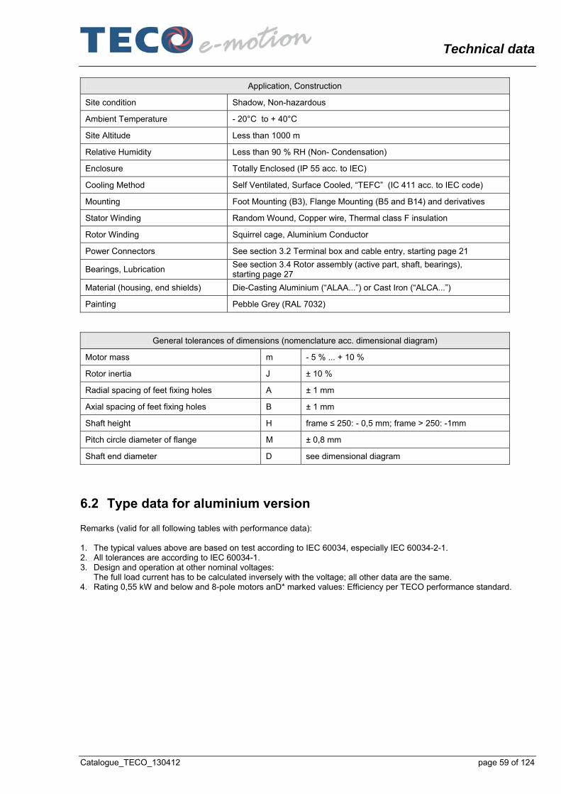
Technical data
Catalogue_TECO_130412 page 59 of 124
Application, Construction
Site condition Shadow, Non-hazardous
Ambient Temperature - 20°C to + 40°C
Site Altitude Less than 1000 m
Relative Humidity Less than 90 % RH (Non- Condensation)
Enclosure Totally Enclosed (IP 55 acc. to IEC)
Cooling Method Self Ventilated, Surface Cooled, “TEFC” (IC 411 acc. to IEC code)
Mounting Foot Mounting (B3), Flange Mounting (B5 and B14) and derivatives
Stator Winding Random Wound, Copper wire, Thermal class F insulation
Rotor Winding Squirrel cage, Aluminium Conductor
Power Connectors See section 3.2 Terminal box and cable entry, starting page 21
Bearings, Lubrication See section 3.4 Rotor assembly (active part, shaft, bearings), starting page 27
Material (housing, end shields) Die-Casting Aluminium (“ALAA...”) or Cast Iron (“ALCA...”)
Painting Pebble Grey (RAL 7032)
General tolerances of dimensions (nomenclature acc. dimensional diagram)
Motor mass m - 5 % ... + 10 %
Rotor inertia J ± 10 %
Radial spacing of feet fixing holes A ± 1 mm
Axial spacing of feet fixing holes B ± 1 mm
Shaft height H frame ≤ 250: - 0,5 mm; frame > 250: -1mm
Pitch circle diameter of flange M ± 0,8 mm
Shaft end diameter D see dimensional diagram
6.2 Type data for aluminium version Remarks (valid for all following tables with performance data): 1. The typical values above are based on test according to IEC 60034, especially IEC 60034-2-1. 2. All tolerances are according to IEC 60034-1. 3. Design and operation at other nominal voltages:
The full load current has to be calculated inversely with the voltage; all other data are the same. 4. Rating 0,55 kW and below and 8-pole motors anD* marked values: Efficiency per TECO performance standard.

Technical data
page 60 of 124 Catalogue_TECO_130412
6.2.1 Aluminium; 400 V; 50 Hz; Class IE2 2-pole:
Po
we
r ra
ting
No
min
al s
pee
d
Fra
me
size
T
ype
cod
e
ALA
A...
No
min
al c
urr
en
t
Lo
cked
ro
tor
curr
en
t (m
ulti
ple
of n
om
ina
l cur
ren
t)
Eff
icie
ncy
at
loa
d p
oin
ts
Po
we
r fa
cto
r at
load
po
ints
No
min
al t
orq
ue
Lo
cked
ro
tor
torq
ue
(mu
ltip
le o
f no
min
al t
orq
ue
)
Pu
ll u
p to
rqu
e
(mu
ltip
le o
f no
min
al t
orq
ue
)
Bre
ak
dow
n to
rque
(m
ulti
ple
of n
om
ina
l to
rqu
e)
Mo
me
nt
of I
nert
ia
Tot
al m
ass
(B3
ve
rsio
n; a
pp
rox.
)
PN nn IN Il /IN η cos φ TN Tl/TN Tp/TN Tb/TN J m
[kW] [rpm] [A] [%] [Nm] kgm2 [kg]
Full load
3/4 load
2/4 load
1/4 load
Full load
3/4 load
2/4 load
1/4 load
0,18 2775 0063M0 0,49 4,41 67,4 67,4 60,4 48,0 0,79 0,69 0,55 0,38 0,62 1,90 1,70 2,00 0,17
x 10-3
5,0
0,25 2785 0063M1 0,65 4,50 69,9 70,0 65,7 49,0 0,79 0,70 0,56 0,39 0,86 1,95 1,70 2,05 0,21
x 10-3
6,0
0,37 2790 0071M0 0,93 4,86 71,0 71,0 66,7 52,5 0,81 0,71 0,55 0,36 1,27 1,90 1,70 2,20 0,17
x 10-3
8,0
0,55 2780 0071M1 1,27 5,32 75,5 76,2 73,3 59,0 0,83 0,75 0,59 0,39 1,89 1,90 1,70 2,20 0,33
x 10-3
9,0
0,75 2815 0080M0 1,63 5,85 77,4 78,6 77,4 66,2 0,86 0,79 0,67 0,44 2,54 3,10 2,70 3,00 0,46
x 10-3
12,0
1,1 2820 0080M1 2,32 6,90 79,6 80,8 80,0 73,1 0,86 0,80 0,68 0,46 3,72 3,35 2,95 3,25 0,75
x 10-3
14,0
1,5 2865 0090S0 3,11 7,71 81,3 82,0 80,9 73,9 0,86 0,80 0,69 0,46 5,00 3,10 2,90 3,30 1,0 x 10⁻³
17,0
2,2 2860 0090L0 4,39 7,45 83,2 84,0 83,2 77,1 0,87 0,82 0,72 0,51 7,34 3,05 2,75 3,20 1,5 x 10⁻³
20,0
3 2880 0100L0 6,06 7,45 84,6 85,5 84,8 78,3 0,85 0,79 0,66 0,45 9,94 3,05 2,55 3,35 4,0 x 10⁻³
27,0
4 2905 0112M0 7,78 7,75 85,8 86,3 85,3 78,9 0,87 0,83 0,75 0,55 13,1 1,95 1,80 2,85 8,25
x 10-3
35,0
5,5 2930 0132S0 11,3 7,05 87,0 87,0 85,6 79,4 0,81 0,75 0,64 0,42 17,9 2,65 2,45 3,05 13,5
x 10-3
51,0
7,5 2920 0132S1 15,7 7,00 88,1 88,4 87,5 80,9 0,79 0,73 0,62 0,41 24,5 2,80 2,50 3,00 16 x 10-3
56,0
11 2950 0160M0 19,9 8,28 89,5 90,5 90,0 85,5 0,89 0,86 0,77 0,57 35,6 2,30 1,80 3,05 38 x 10-3
87,0
15 2950 0160M1 26,6 8,46 90,5 91,5 91,0 87,5 0,90 0,86 0,78 0,58 48,5 2,45 1,95 3,15 48 x 10-3
98,0
18,5 2945 0160L0 32,2 9,00 91,0 92,0 92,0 88,5 0,91 0,91 0,86 0,71 60,0 2,60 1,85 3,10 59 x 10-3
109

Technical data
Catalogue_TECO_130412 page 61 of 124
4-pole:
Po
we
r ra
ting
No
min
al s
pee
d
Fra
me
size
T
ype
cod
e
ALA
A...
No
min
al c
urr
en
t
Lo
cked
ro
tor
curr
en
t (m
ulti
ple
of n
om
ina
l cur
ren
t)
Eff
icie
ncy
at
loa
d p
oin
ts
Po
we
r fa
cto
r at
load
po
ints
No
min
al t
orq
ue
Lo
cked
ro
tor
torq
ue
(mu
ltip
le o
f no
min
al t
orq
ue
)
Pu
ll u
p to
rqu
e
(mu
ltip
le o
f no
min
al t
orq
ue
)
Bre
ak
dow
n to
rque
(m
ulti
ple
of n
om
ina
l to
rqu
e)
Mo
me
nt
of I
nert
ia
Tot
al m
ass
(B3
ve
rsio
n; a
pp
rox.
)
PN nn IN Il /IN η cos φ TN Tl/TN Tp/TN Tb/TN J m
[kW] [rpm] [A] [%] [Nm] kgm2 [kg]
Full load
3/4 load
2/4 load
1/4 load
Full load
3/4 load
2/4 load
1/4 load
0,18 1375 0063M1 0,54 3,90 65,0 63,8 58,2 43,6 0,75 0,64 0,50 0,35 1,25 2,00 1,80 2,00 0,43
x 10-3
6,0
0,25 1380 0071M0 0,67 4,20 69,5 70,1 66,2 51,8 0,77 0,67 0,52 0,35 1,73 2,00 1,75 2,00 0,67
x 10-3
8,0
0,37 1385 0071M1 1,02 4,20 69,5 69,9 66,3 52,2 0,75 0,65 0,50 0,33 2,55 2,05 1,80 2,05 0,8 x10⁻³
9,0
0,55 1435 0080M0 1,34 6,60 78,1 78,1 75,2 63,6 0,76 0,69 0,56 0,37 3,66 2,55 2,20 2,80 2,6 x10⁻³
13,0
0,75 1430 0080M1 1,75 6,15 79,6 79,6 76,1 67,1 0,78 0,71 0,59 0,38 5,01 2,45 2,15 2,70 3,0 x10⁻³
14,0
1,1 1435 0090S0 2,44 6,95 81,4 81,4 79,2 71,4 0,80 0,72 0,58 0,37 7,32 2,65 2,30 3,05 3,5 x10⁻³
15,0
1,5 1430 0090L0 3,27 7,05 82,8 83,2 81,9 74,6 0,80 0,72 0,59 0,40 10,0 2,75 2,35 3,15 4,5 x10⁻³
19,0
2,2 1435 0100L0 4,62 6,95 84,3 86,3 86,5 81,0 0,82 0,77 0,64 0,43 14,6 2,80 2,55 2,85 9,8 x10⁻³
26,0
3 1430 0100L1 6,45 6,50 85,5 86,5 86,7 80,8 0,79 0,73 0,60 0,42 20,0 2,70 2,50 2,75 11 x10-3
28,0
4 1440 0112M0 7,98 7,85 86,6 87,0 87,0 81,4 0,84 0,79 0,68 0,47 26,5 2,85 2,30 2,85 16,3
x 10-3
35,0
5,5 1450 0132S0 10,8 7,40 87,7 88,2 86,9 81,0 0,84 0,79 0,67 0,46 36,2 2,55 2,15 2,95 36 x10-3
55,0
7,5 1455 0132M0 14,5 7,50 88,7 88,8 88,0 83,1 0,84 0,79 0,68 0,47 49,2 2,65 2,15 3,00 44 x10-3
59,0
11 1465 0160M0 20,5 7,80 90,0 90,5 90,0 86,0 0,86 0,82 0,73 0,52 71,7 2,00 1,50 2,40 74 x10-3
80,0
15 1465 0160L0 27,5 8,00 91,0 91,5 91,0 88,0 0,87 0,83 0,74 0,54 97,7 2,20 1,55 2,55 107
x 10-3
108
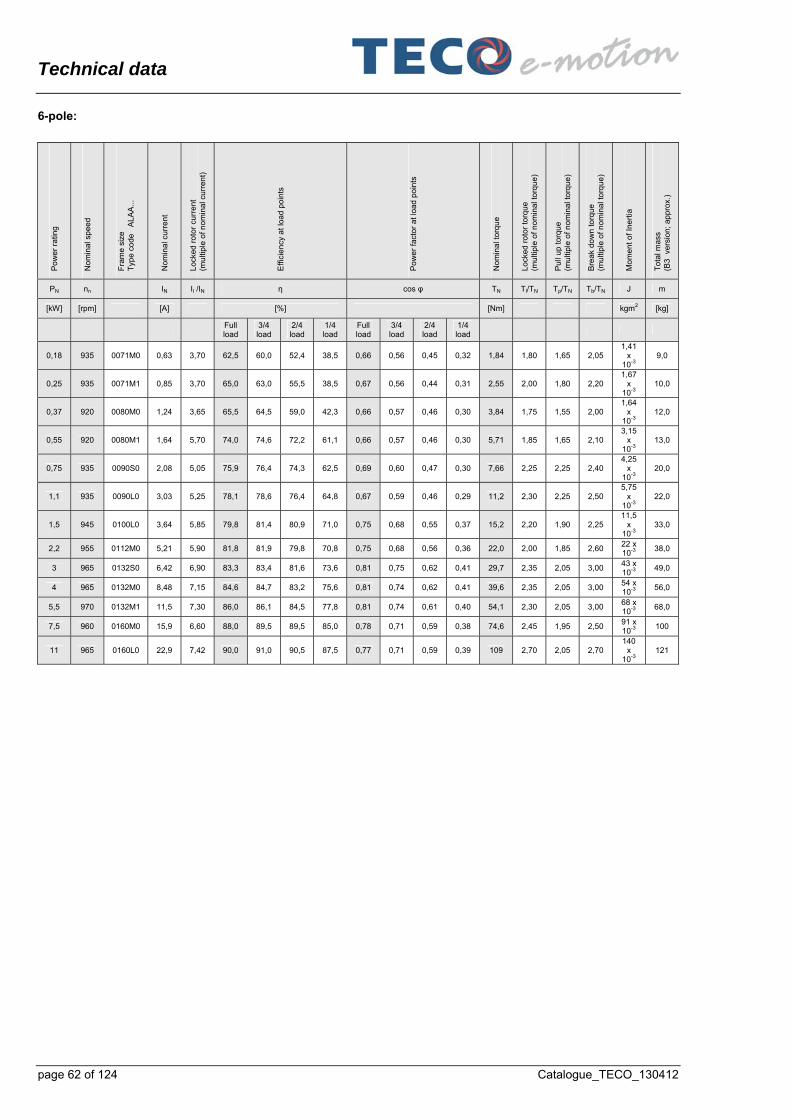
Technical data
page 62 of 124 Catalogue_TECO_130412
6-pole:
Po
we
r ra
ting
No
min
al s
pee
d
Fra
me
size
T
ype
cod
e
ALA
A...
No
min
al c
urr
en
t
Lo
cked
ro
tor
curr
en
t (m
ulti
ple
of n
om
ina
l cur
ren
t)
Eff
icie
ncy
at
loa
d p
oin
ts
Po
we
r fa
cto
r at
load
po
ints
No
min
al t
orq
ue
Lo
cked
ro
tor
torq
ue
(mu
ltip
le o
f no
min
al t
orq
ue
)
Pu
ll u
p to
rqu
e
(mu
ltip
le o
f no
min
al t
orq
ue
)
Bre
ak
dow
n to
rque
(m
ulti
ple
of n
om
ina
l to
rqu
e)
Mo
me
nt
of I
nert
ia
Tot
al m
ass
(B3
ve
rsio
n; a
pp
rox.
)
PN nn IN Il /IN η cos φ TN Tl/TN Tp/TN Tb/TN J m
[kW] [rpm] [A] [%] [Nm] kgm2 [kg]
Full load
3/4 load
2/4 load
1/4 load
Full load
3/4 load
2/4 load
1/4 load
0,18 935 0071M0 0,63 3,70 62,5 60,0 52,4 38,5 0,66 0,56 0,45 0,32 1,84 1,80 1,65 2,05 1,41
x 10-3
9,0
0,25 935 0071M1 0,85 3,70 65,0 63,0 55,5 38,5 0,67 0,56 0,44 0,31 2,55 2,00 1,80 2,20 1,67
x 10-3
10,0
0,37 920 0080M0 1,24 3,65 65,5 64,5 59,0 42,3 0,66 0,57 0,46 0,30 3,84 1,75 1,55 2,00 1,64
x 10-3
12,0
0,55 920 0080M1 1,64 5,70 74,0 74,6 72,2 61,1 0,66 0,57 0,46 0,30 5,71 1,85 1,65 2,10 3,15
x 10-3
13,0
0,75 935 0090S0 2,08 5,05 75,9 76,4 74,3 62,5 0,69 0,60 0,47 0,30 7,66 2,25 2,25 2,40 4,25
x 10-3
20,0
1,1 935 0090L0 3,03 5,25 78,1 78,6 76,4 64,8 0,67 0,59 0,46 0,29 11,2 2,30 2,25 2,50 5,75
x 10-3
22,0
1,5 945 0100L0 3,64 5,85 79,8 81,4 80,9 71,0 0,75 0,68 0,55 0,37 15,2 2,20 1,90 2,25 11,5
x 10-3
33,0
2,2 955 0112M0 5,21 5,90 81,8 81,9 79,8 70,8 0,75 0,68 0,56 0,36 22,0 2,00 1,85 2,60 22 x 10-3
38,0
3 965 0132S0 6,42 6,90 83,3 83,4 81,6 73,6 0,81 0,75 0,62 0,41 29,7 2,35 2,05 3,00 43 x 10-3
49,0
4 965 0132M0 8,48 7,15 84,6 84,7 83,2 75,6 0,81 0,74 0,62 0,41 39,6 2,35 2,05 3,00 54 x 10-3
56,0
5,5 970 0132M1 11,5 7,30 86,0 86,1 84,5 77,8 0,81 0,74 0,61 0,40 54,1 2,30 2,05 3,00 68 x 10-3
68,0
7,5 960 0160M0 15,9 6,60 88,0 89,5 89,5 85,0 0,78 0,71 0,59 0,38 74,6 2,45 1,95 2,50 91 x 10-3
100
11 965 0160L0 22,9 7,42 90,0 91,0 90,5 87,5 0,77 0,71 0,59 0,39 109 2,70 2,05 2,70 140
x 10-3
121

Technical data
Catalogue_TECO_130412 page 63 of 124
8-pole:
Po
we
r ra
ting
No
min
al s
pee
d
Fra
me
size
T
ype
cod
e
ALA
A...
No
min
al c
urr
en
t
Lo
cked
ro
tor
curr
en
t (m
ulti
ple
of n
om
ina
l cur
ren
t)
Eff
icie
ncy
at
loa
d p
oin
ts
Po
we
r fa
cto
r at
load
po
ints
No
min
al t
orq
ue
Lo
cked
ro
tor
torq
ue
(mu
ltip
le o
f no
min
al t
orq
ue
)
Pu
ll u
p to
rqu
e
(mu
ltip
le o
f no
min
al t
orq
ue
)
Bre
ak
dow
n to
rque
(m
ulti
ple
of n
om
ina
l to
rqu
e)
Mo
me
nt
of I
nert
ia
Tot
al m
ass
(B3
ve
rsio
n; a
pp
rox.
)
PN nn IN Il /IN η cos φ TN Tl/TN Tp/TN Tb/TN J m
[kW] [rpm] [A] [%] [Nm] kgm2 [kg]
Full load
3/4 load
2/4 load
1/4 load
Full load
3/4 load
2/4 load
1/4 load
0,18 690 0080M0 0,86 3,95 55,0 51,5 43,5 29,5 0,55 0,47 0,39 0,28 0,28 1,65 4,55 2,00 1,9 x10⁻³
13,0
0,25 690 0080M1 1,13 3,00 58,0 54,5 47,0 29,5 0,55 0,47 0,39 0,28 3,46 1,65 1,55 2,00 2,5 x10⁻³
14,0
0,37 695 0090S0 1,38 3,50 62,0 59,5 53,0 35,0 0,63 0,55 0,44 0,31 5,08 1,65 1,55 2,00 4,1 x10⁻³
20,0
0,55 690 0090L0 2,07 3,50 63,0 60,5 54,0 36,5 0,61 0,53 0,43 0,30 7,61 1,70 1,60 2,05 4,9 x10⁻³
22,0
0,75 695 0100L0 2,32 3,90 71,8 73,0 69,5 56,0 0,65 0,56 0,45 0,29 10,3 1,90 1,70 2,00 8,5 x10⁻³
27,0
1,1 695 0100L1 3,22 4,10 74,7 76,0 73,5 6,10 0,66 0,58 0,46 0,29 15,1 1,90 1,70 2,00 12,3
x 10-3
33,0
1,5 700 0112M0 4,24 4,25 76,8 77,5 75,0 62,0 0,67 0,57 0,44 0,27 20,5 1,85 1,80 2,20 14,6
x 10-3
38,0
2,2 715 0132S0 5,55 5,15 79,4 80,0 79,5 70,0 0,72 0,63 0,50 0,31 29,4 1,75 1,45 2,25 34 x10-3
53,0
3 715 0132M0 7,40 5,15 81,3 82,0 81,0 73,0 0,72 0,64 0,50 0,31 40,0 1,75 1,45 2,30 45 x10-3
64,0
4 715 0160M0 9,73 5,65 83,0 84,0 82,0 73,5 0,72 0,63 0,51 0,31 53,4 1,70 1,60 2,45 86 x10-3
90,0
5,5 715 0160M1 13,2 5,30 84,5 84,0 82,5 74,0 0,71 0,63 0,51 0,31 73,4 1,65 1,60 2,40 86 x10-3
107
7,5 720 0160L0 18,0 5,85 86,0 86,0 84,0 76,0 0,70 0,61 0,49 0,30 99,4 1,90 1,80 2,70 147
x 10-3
122

Technical data
page 64 of 124 Catalogue_TECO_130412
6.2.2 Aluminium; 460 V; 60 Hz; Class IE2 2-pole:
Po
we
r ra
ting
No
min
al s
pee
d
Fra
me
size
T
ype
cod
e
ALA
A...
No
min
al c
urr
en
t
Lo
cked
ro
tor
curr
en
t (m
ulti
ple
of n
om
ina
l cur
ren
t)
Eff
icie
ncy
at
loa
d p
oin
ts
Po
we
r fa
cto
r at
load
po
ints
No
min
al t
orq
ue
Lo
cked
ro
tor
torq
ue
(mu
ltip
le o
f no
min
al t
orq
ue
)
Pu
ll u
p to
rqu
e
(mu
ltip
le o
f no
min
al t
orq
ue
)
Bre
ak
dow
n to
rque
(m
ulti
ple
of n
om
ina
l to
rqu
e)
Mo
me
nt
of I
nert
ia
Tot
al m
ass
(B3
ve
rsio
n; a
pp
rox.
)
PN nn IN Il /IN η cos φ TN Tl/TN Tp/TN Tb/TN J m
[kW] [rpm] [A] [%] [Nm] kgm2 [kg]
Full load
3/4 load
2/4 load
1/4 load
Full load
3/4 load
2/4 load
1/4 load
0,18 3390 0063M0 0,45 5,40 69,0 67,3 61,3 49,2 0,73 0,64 0,51 0,36 0,51 2,40 2,00 2,40 0,25
x 10-3
5,0
0,25 3400 0063M1 0,59 5,35 70,0 69,0 63,8 49,2 0,76 0,67 0,54 0,37 0,70 2,35 1,95 2,35 0,25
x 10-3
6,0
0,37 3440 0071M0 0,82 5,90 75,0 73,7 68,7 55,2 0,76 0,65 0,51 0,34 1,03 2,25 2,20 3,40 0,25
x 10-3
8,0
0,55 3440 0071M1 1,05 6,60 79,0 78,8 75,4 63,6 0,84 0,74 0,60 0,39 1,53 2,20 2,15 3,35 0,5 x 10⁻³
9,0
0,75 3465 0080M0 1,42 8,45 80,7 80,3 77,5 68,0 0,82 0,75 0,63 0,43 2,07 3,30 3,10 3,55 0,75
x 10-3
12,0
1,1 3465 0080M1 1,99 9,05 82,5 82,5 80,4 72,0 0,84 0,78 0,66 0,45 3,03 3,50 3,30 3,75 1,0 x 10⁻³
14,0
1,5 3490 0090S0 2,67 9,40 84,0 83,8 81,6 73,0 0,84 0,78 0,67 0,46 4,10 3,10 2,95 3,40 1,5 x 10⁻³
17,0
2,2 3480 0090L0 3,69 9,50 85,5 85,5 84,2 78,0 0,88 0,83 0,74 0,52 6,03 3,00 2,85 3,30 2,0 x 10⁻³
20,0
3 3495 0100L0 5,12 9,45 87,5 87,5 86,0 79,0 0,84 0,78 0,67 0,45 8,19 2,90 2,50 3,30 4,0 x 10⁻³
27,0
4 3515 0112M0 6,63 9,40 87,5 87,5 85,8 79,0 0,87 0,83 0,74 0,55 10,9 2,45 2,10 3,45 8,25
x 10-3
35,0
5,5 3535 0132S0 10,2 7,75 88,5 88,0 85,5 77,0 0,77 0,71 0,60 0,40 14,9 3,00 2,45 3,10 13,5
x 10-3
51,0
7,5 3550 0132S1 13,8 7,95 89,5 89,2 87,5 79,3 0,76 0,70 0,60 0,36 20,3 3,00 2,45 3,10 16 x 10-3
56,0
11 3550 0160M0 17,2 9,60 90,2 90,5 89,0 82,0 0,89 0,86 0,78 0,60 29,6 2,95 2,20 3,65 38 x 10-3
87,0
15 3555 0160M1 23,3 9,65 90,2 90,5 89,5 84,0 0,90 0,87 0,79 0,60 40,3 3,10 2,20 3,5 48 x 10-3
98,0
18,5 3545 0160L0 27,8 9,70 91,7 92,0 91,5 87,5 0,91 0,90 0,86 0,71 49,8 2,75 1,85 3,05 59 x 10-3
109

Technical data
Catalogue_TECO_130412 page 65 of 124
4-pole:
Po
we
r ra
ting
No
min
al s
pee
d
Fra
me
size
T
ype
cod
e
ALA
A...
No
min
al c
urr
en
t
Lo
cked
ro
tor
curr
en
t (m
ulti
ple
of n
om
ina
l cur
ren
t)
Eff
icie
ncy
at
loa
d p
oin
ts
Po
we
r fa
cto
r at
load
po
ints
No
min
al t
orq
ue
Lo
cked
ro
tor
torq
ue
(mu
ltip
le o
f no
min
al t
orq
ue
)
Pu
ll u
p to
rqu
e
(mu
ltip
le o
f no
min
al t
orq
ue
)
Bre
ak
dow
n to
rque
(m
ulti
ple
of n
om
ina
l to
rqu
e)
Mo
me
nt
of I
nert
ia
Tot
al m
ass
(B3
ve
rsio
n; a
pp
rox.
)
PN nn IN Il /IN η cos φ TN Tl/TN Tp/TN Tb/TN J m
[kW] [rpm] [A] [%] [Nm] kgm2 [kg]
Full load
3/4 load
2/4 load
1/4 load
Full load
3/4 load
2/4 load
1/4 load
0,18 1700 0063M1 0,49 4,50 69,0 66,3 60,2 45,7 0,67 0,56 0,44 0,30 1,01 2,3 2,2 2,55 0,50
x 10-3
6,0
0,25 1705 0071M0 0,62 4,90 72,5 71,2 66,5 52,6 0,70 0,60 0,47 0,31 1,40 2,15 2,05 2,50 0,75
x 10-3
8,0
0,37 1705 0071M1 0,92 4,95 74,0 72,8 68,4 54,7 0,69 0,59 0,46 0,30 2,07 2,20 2,15 2,60 0,75
x 10-3
9,0
0,55 1745 0080M0 1,18 7,60 81,2 80,2 76,8 65,6 0,72 0,64 0,52 0,34 3,01 3,1 2,85 3,4 2,5 x10⁻³
13,0
0,75 1745 0080M1 1,55 7,15 82,5 81,7 78,6 67,8 0,74 0,66 0,54 0,35 4,10 2,95 2,70 3,25 3,0 x10⁻³
14,0
1,1 1745 0090S0 2,11 8,55 84,0 83,8 81,7 73,0 0,78 0,70 0,56 0,35 6,02 3,30 2,70 3,85 3,5 x10⁻³
15,0
1,5 1745 0090L0 2,80 8,55 84,0 84,0 82,2 75,0 0,80 0,72 0,59 0,37 8,20 3,30 2,70 3,85 4,5 x10⁻³
19,0
2,2 1745 0100L0 3,92 8,95 87,5 88,0 87,0 80,6 0,81 0,75 0,64 0,41 12,0 3,15 2,65 3,20 9,75
x 10-3
26,0
3 1740 0100L1 5,45 8,10 87,5 88,2 87,3 81,2 0,79 0,74 0,63 0,40 16,5 3,10 2,60 3,15 11,0
x 10-3
28,0
4 1750 0112M0 7,04 9,20 87,5 88,2 87,3 82,0 0,82 0,76 0,64 0,43 21,8 3,20 2,70 3,40 16,3
x 10-3
35,0
5,5 1760 0132S0 9,35 8,60 89,5 89,3 87,5 80,5 0,83 0,77 0,65 0,43 29,8 2,90 2,40 3,40 36,3
x 10-3
55,0
7,5 1760 0132M0 12,8 8,50 89,5 89,5 87,8 81,7 0,83 0,77 0,66 0,44 40,7 3,00 2,50 3,60 44 x10-3
59,0
11 1770 0160M0 17,9 8,95 91,0 91,0 90,5 86,0 0,85 0,81 0,71 0,49 59,3 2,25 1,60 2,75 74 x10-3
80,0
15 1770 0160L0 24,1 9,35 91,5 92,0 92,0 88,0 0,86 0,81 0,71 0,49 80,9 2,50 1,75 2,95 107
x 10-3
108
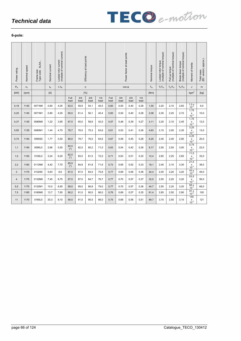
Technical data
page 66 of 124 Catalogue_TECO_130412
6-pole:
Po
we
r ra
ting
No
min
al s
pee
d
Fra
me
size
T
ype
cod
e
ALA
A...
No
min
al c
urr
en
t
Lo
cked
ro
tor
curr
en
t (m
ulti
ple
of n
om
ina
l cur
ren
t)
Eff
icie
ncy
at
loa
d p
oin
ts
Po
we
r fa
cto
r at
load
po
ints
No
min
al t
orq
ue
Lo
cked
ro
tor
torq
ue
(mu
ltip
le o
f no
min
al t
orq
ue
)
Pu
ll u
p to
rqu
e
(mu
ltip
le o
f no
min
al t
orq
ue
)
Bre
ak
dow
n to
rque
(m
ulti
ple
of n
om
ina
l to
rqu
e)
Mo
me
nt
of I
nert
ia
Tot
al m
ass
(B3
ve
rsio
n; a
pp
rox.
)
PN nn IN Il /IN η cos φ TN Tl/TN Tp/TN Tb/TN J m
[kW] [rpm] [A] [%] [Nm] kgm2 [kg]
Full load
3/4 load
2/4 load
1/4 load
Full load
3/4 load
2/4 load
1/4 load
0,18 1145 0071M0 0,60 4,05 63,5 59,9 54,1 40,5 0,60 0,50 0,40 0,28 1,50 2,20 2,10 2,65 1,5 x 10⁻³
9,0
0,25 1145 0071M1 0,80 4,05 65,0 61,4 56,1 40,4 0,60 0,50 0,40 0,28 2,08 2,30 2,20 2,72 1,75
x 10-3
10,0
0,37 1135 0080M0 1,22 3,95 67,5 65,0 58,6 42,0 0,57 0,48 0,39 0,27 3,11 2,20 2,10 2,45 1,75
x 10-3
12,0
0,55 1135 0080M1 1,44 4,75 78,7 78,5 75,3 63,6 0,61 0,53 0,41 0,26 4,63 2,10 2,00 2,35 3,25
x 10-3
13,0
0,75 1145 0090S0 1,77 5,50 80,0 79,7 76,5 64,6 0,67 0,58 0,45 0,28 6,25 2,40 2,40 2,90 4,25
x 10-3
20,0
1,1 1145 0090L0 2,66 5,55 82,5 (*)
82,5 80,2 71,0 0,63 0,54 0,42 0,26 9,17 2,55 2,55 3,00 5,75
x 10-3
22,0
1,5 1155 0100L0 3,24 6,20 82,5 (*)
83,0 81,5 72,0 0,71 0,63 0,51 0,32 12,4 2,65 2,25 2,65 11,5
x 10-3
33,0
2,2 1160 0112M0 4,42 7,70 85,5 (*)
84,8 81,8 71,6 0,73 0,65 0,52 0,33 18,1 2,45 2,10 3,30 21,5
x 10-3
38,0
3 1175 0132S0 5,63 8,6 87,5 87,0 84,5 75,8 0,77 0,69 0,56 0,36 24,4 2,50 2,20 3,20 43 x 10-3
49,0
4 1175 0132M0 7,45 8,75 87,5 87,0 84,7 76,7 0,77 0,70 0,57 0,37 32,5 2,50 2,20 3,20 53,5
x 10-3
56,0
5,5 1175 0132M1 10,0 8,95 89,5 89,0 86,8 79,0 0,77 0,70 0,57 0,36 44,7 2,50 2,20 3,20 68 x 10-3
68,0
7,5 1165 0160M0 13,7 7,65 90,2 91,0 90,5 86,0 0,76 0,69 0,57 0,35 61,4 2,85 2,50 2,90 91 x 10-3
100
11 1170 0160L0 20,3 8,10 90,5 91,5 90,5 86,0 0,75 0,69 0,56 0,51 89,7 3,15 2,50 3,15 140
x 10-3
121

Technical data
Catalogue_TECO_130412 page 67 of 124
8-pole:
Po
we
r ra
ting
No
min
al s
pee
d
Fra
me
size
T
ype
cod
e
ALA
A...
No
min
al c
urr
en
t
Lo
cked
ro
tor
curr
en
t (m
ulti
ple
of n
om
ina
l cur
ren
t)
Eff
icie
ncy
at
loa
d p
oin
ts
Po
we
r fa
cto
r at
load
po
ints
No
min
al t
orq
ue
Lo
cked
ro
tor
torq
ue
(mu
ltip
le o
f no
min
al t
orq
ue
)
Pu
ll u
p to
rqu
e
(mu
ltip
le o
f no
min
al t
orq
ue
)
Bre
ak
dow
n to
rque
(m
ulti
ple
of n
om
ina
l to
rqu
e)
Mo
me
nt
of I
nert
ia
Tot
al m
ass
(B3
ve
rsio
n; a
pp
rox.
)
PN nn IN Il /IN η cos φ TN Tl/TN Tp/TN Tb/TN J m
[kW] [rpm] [A] [%] [Nm] kgm2 [kg]
Full load
3/4 load
2/4 load
1/4 load
Full load
3/4 load
2/4 load
1/4 load
0,18 850 0080M0 0,84 3,10 56,5 53,0 44,5 27,0 0,48 0,41 0,33 0,24 2,02 2,00 2,00 2,45 2,0 x10⁻³
13,0
0,25 850 0080M1 1,11 3,10 59,5 56,0 48,0 30,0 0,48 0,41 0,33 0,24 2,81 2,00 2,00 2,45 2,5 x10⁻³
14,0
0,37 855 0090S0 1,17 4,20 68,5 66,0 59,0 42,0 0,58 0,50 0,40 0,28 4,13 2,00 2,00 2,55 4,0 x10⁻³
20,0
0,55 855 0090L0 1,79 4,05 69,0 67,5 61,0 43,5 0,56 0,48 0,38 0,26 6,14 2,05 2,00 2,50 4,75
x 10-3
22,0
0,75 860 0100L0 2,23 4,55 74,0 73,5 70,5 56,0 0,57 0,49 0,38 0,24 8,32 2,30 2,00 2,30 8,5 x10⁻³
27,0
1,1 860 0100L1 3,06 4,75 77,0 77,0 74,0 61,0 0,59 0,50 0,39 0,24 12,2 2,30 2,00 2,30 12,3
x 10-3
33,0
1,5 855 0112M0 3,80 4,75 80,0 80,0 76,0 64,0 0,62 0,53 0,40 0,25 16,8 2,10 1,95 2,60 14,5
x 10-3
38,0
2,2 880 0132S0 4,78 7,30 8,25 82,5 80,0 69,5 0,70 0,61 0,48 0,30 23,9 2,25 1,85 3,30 34 x10-3
53,0
3 885 0132M0 6,44 7,20 83,5 83,5 81,0 71,5 0,70 0,62 0,49 0,30 32,4 2,25 1,85 3,30 45 x10-3
64,0
4 870 0160M0 8,56 6,45 85,0 84,5 82,0 72,5 0,69 0,60 0,47 0,30 43,9 1,90 1,80 2,65 86 x10-3
90,0
5,5 870 0160M1 12,2 5,75 84,5 84,5 82,0 72,0 0,67 0,58 0,45 0,29 60,3 1,95 1,85 2,60 68 x10-3
107
7,5 870 0160L1 16,4 6,10 86,5 86,0 83,5 74,5 0,67 0,58 0,44 0,29 82,3 2,20 2,10 2,90 147
x 10-3
122
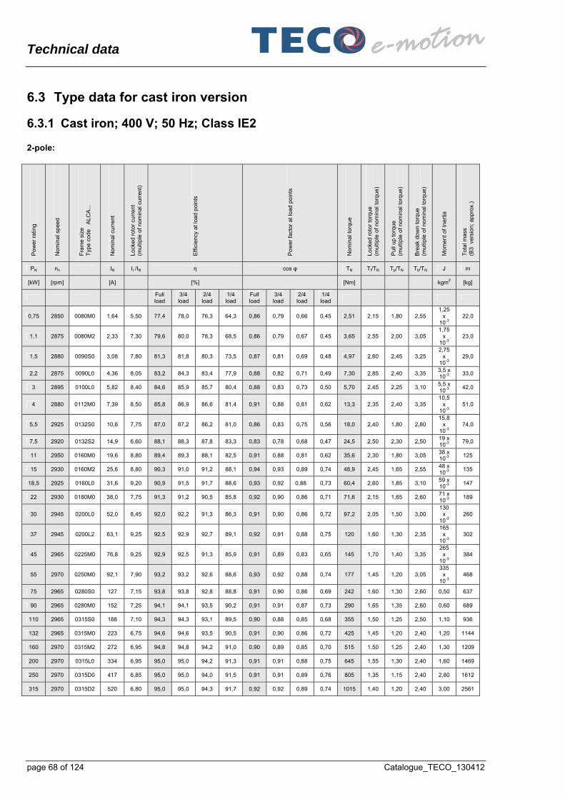
Technical data
page 68 of 124 Catalogue_TECO_130412
6.3 Type data for cast iron version
6.3.1 Cast iron; 400 V; 50 Hz; Class IE2 2-pole:
Po
we
r ra
ting
No
min
al s
pee
d
Fra
me
size
T
ype
cod
e
AL
CA
...
No
min
al c
urr
en
t
Lo
cked
ro
tor
curr
en
t (m
ulti
ple
of n
om
ina
l cur
ren
t)
Eff
icie
ncy
at
loa
d p
oin
ts
Po
we
r fa
cto
r at
load
po
ints
No
min
al t
orq
ue
Lo
cked
ro
tor
torq
ue
(mu
ltip
le o
f no
min
al t
orq
ue
)
Pu
ll u
p to
rqu
e
(mu
ltip
le o
f no
min
al t
orq
ue
)
Bre
ak d
ow
n to
rque
(m
ulti
ple
of n
om
ina
l to
rqu
e)
Mo
me
nt
of I
nert
ia
Tot
al m
ass
(B3
ve
rsio
n; a
pp
rox.
)
PN nn IN Il /IN η cos φ TN Tl/TN Tp/TN Tb/TN J m
[kW] [rpm] [A] [%] [Nm] kgm2 [kg]
Full load
3/4 load
2/4 load
1/4 load
Full load
3/4 load
2/4 load
1/4 load
0,75 2850 0080M0 1,64 5,50 77,4 78,0 76,3 64,3 0,86 0,79 0,66 0,45 2,51 2,15 1,80 2,55 1,25
x 10-3
22,0
1,1 2875 0080M2 2,33 7,30 79,6 80,0 78,3 68,5 0,86 0,79 0,67 0,45 3,65 2,55 2,00 3,05 1,75
x 10-3
23,0
1,5 2880 0090S0 3,08 7,80 81,3 81,8 80,3 73,5 0,87 0,81 0,69 0,48 4,97 2,60 2,45 3,25 2,75
x 10-3
29,0
2,2 2875 0090L0 4,36 8,05 83,2 84,3 83,4 77,9 0,88 0,82 0,71 0,49 7,30 2,85 2,40 3,35 3,5 x 10⁻³
33,0
3 2895 0100L0 5,82 8,40 84,6 85,9 85,7 80,4 0,88 0,83 0,73 0,50 5,70 2,45 2,25 3,10 5,5 x 10⁻³
42,0
4 2880 0112M0 7,39 8,50 85,8 86,9 86,6 81,4 0,91 0,88 0,81 0,62 13,3 2,35 2,40 3,35 10,5
x 10-3
51,0
5,5 2925 0132S0 10,6 7,75 87,0 87,2 86,2 81,0 0,86 0,83 0,75 0,56 18,0 2,40 1,80 2,80 15,8
x 10-3
74,0
7,5 2920 0132S2 14,9 6,60 88,1 88,3 87,8 83,3 0,83 0,78 0,68 0,47 24,5 2,50 2,30 2,50 19 x 10-3
79,0
11 2950 0160M0 19,6 8,80 89,4 89,3 88,1 82,5 0,91 0,88 0,81 0,62 35,6 2,30 1,80 3,05 38 x 10-3
125
15 2930 0160M2 25,6 8,80 90,3 91,0 91,2 88,1 0,94 0,93 0,89 0,74 48,9 2,45 1,65 2,55 48 x 10-3
135
18,5 2925 0160L0 31,6 9,20 90,9 91,5 91,7 88,6 0,93 0,92 0,88 0,73 60,4 2,60 1,85 3,10 59 x 10-3
147
22 2930 0180M0 38,0 7,75 91,3 91,2 90,5 85,8 0,92 0,90 0,86 0,71 71,6 2,15 1,65 2,60 71 x 10-3
189
30 2945 0200L0 52,0 8,45 92,0 92,2 91,3 86,3 0,91 0,90 0,86 0,72 97,2 2,05 1,50 3,00 130
x 10-3
260
37 2945 0200L2 63,1 9,25 92,5 92,9 92,7 89,1 0,92 0,91 0,88 0,75 120 1,60 1,30 2,35 165
x 10-3
302
45 2965 0225M0 76,8 9,25 92,9 92,5 91,3 85,9 0,91 0,89 0,83 0,65 145 1,70 1,40 3,35 265
x 10-3
384
55 2970 0250M0 92,1 7,90 93,2 93,2 92,6 88,6 0,93 0,92 0,88 0,74 177 1,45 1,20 3,05 335
x 10-3
468
75 2965 0280S0 127 7,15 93,8 93,8 92,8 88,8 0,91 0,90 0,86 0,69 242 1,60 1,30 2,60 0,50 637
90 2965 0280M0 152 7,25 94,1 94,1 93,5 90,2 0,91 0,91 0,87 0,73 290 1,65 1,35 2,60 0,60 689
110 2965 0315S0 188 7,10 94,3 94,3 93,1 89,5 0,90 0,88 0,85 0,68 355 1,50 1,25 2,50 1,10 936
132 2965 0315M0 223 6,75 94,6 94,6 93,5 90,5 0,91 0,90 0,86 0,72 425 1,45 1,20 2,40 1,20 1144
160 2970 0315M2 272 6,95 94,8 94,8 94,2 91,0 0,90 0,89 0,85 0,70 515 1,50 1,25 2,40 1,30 1209
200 2970 0315L0 334 6,95 95,0 95,0 94,2 91,3 0,91 0,91 0,88 0,75 645 1,55 1,30 2,40 1,60 1469
250 2970 0315D0 417 6,85 95,0 95,0 94,0 91,5 0,91 0,91 0,89 0,76 805 1,35 1,15 2,40 2,80 1612
315 2970 0315D2 520 6,80 95,0 95,0 94,3 91,7 0,92 0,92 0,89 0,74 1015 1,40 1,20 2,40 3,00 2561

Technical data
Catalogue_TECO_130412 page 69 of 124
4-pole:
Po
we
r ra
ting
No
min
al s
pee
d
Fra
me
size
T
ype
cod
e
AL
CA
...
No
min
al c
urr
en
t
Lo
cked
ro
tor
curr
en
t (m
ulti
ple
of n
om
ina
l cur
ren
t)
Eff
icie
ncy
at
loa
d p
oin
ts
Po
we
r fa
cto
r at
load
po
ints
No
min
al t
orq
ue
Lo
cked
ro
tor
torq
ue
(mu
ltip
le o
f no
min
al t
orq
ue
)
Pu
ll u
p to
rqu
e
(mu
ltip
le o
f no
min
al t
orq
ue
)
Bre
ak
dow
n to
rque
(m
ulti
ple
of n
om
ina
l to
rqu
e)
Mo
me
nt
of I
nert
ia
Tot
al m
ass
(B3
ve
rsio
n; a
pp
rox.
)
PN nn IN Il /IN η cos φ TN Tl/TN Tp/TN Tb/TN J m
[kW] [rpm] [A] [%] [Nm] kgm2 [kg]
Full load
3/4 load
2/4 load
1/4 load
Full load
3/4 load
2/4 load
1/4 load
0,55 1425 0080M0 1,40 5,70 78,1 78,0 75,1 64,1 0,73 0,62 0,48 0,30 3,69 2,90 2,60 3,05 2,5 x10⁻³
23,0
0,75 1415 0080M2 1,85 5,95 79,6 79,5 76,9 66,3 0,74 0,64 0,50 0,31 5,06 3,00 3,30 3,25 3,25
x 10-3
25,0
1,1 1445 0090S0 2,57 7,40 81,4 81,4 78,9 69,8 0,76 0,67 0,53 0,34 7,26 2,70 2,05 3,25 4,25
x 10-3
30,0
1,5 1435 0090L0 3,23 7,10 82,8 83,7 82,6 75,7 0,81 0,73 0,60 0,38 9,97 2,50 1,80 2,90 5,5 x10⁻³
35,0
2,2 1450 0100L0 4,62 7,15 84,3 85,0 84,1 76,1 0,82 0,74 0,61 0,39 14,5 1,95 1,55 2,65 10,2
x 10-3
42,0
3 1445 0100L2 6,18 7,10 85,5 85,9 84,8 77,3 0,82 0,75 0,63 0,40 19,8 1,95 1,55 2,80 12,5
x 10-
48,0
4 1450 0112M0 7,84 7,40 86,6 87,6 87,5 83,2 0,85 0,81 0,71 0,48 26,3 2,20 2,00 2,70 21 x10-
50,0
5,5 1455 0132S0 10,6 7,65 87,7 88,7 88,6 84,5 0,86 0,81 0,70 0,47 36,1 2,55 2,10 3,05 31 x10-
79,0
7,5 1460 0132M0 14,5 7,70 88,7 89,6 89,5 85,3 0,84 0,79 0,67 0,45 49,1 2,75 2,00 3,05 36 x10-
98,0
11 1465 0160M0 20,4 7,85 89,8 90,6 90,7 87,1 0,87 0,83 0,75 0,53 71,6 2,00 1,50 2,40 74 x10-
125
15 1470 0160L0 27,6 7,95 90,6 91,3 91,2 88,1 0,87 0,83 0,74 0,52 97,3 2,20 1,55 2,55 107
x 10-
135
18,5 1475 0180M0 34,2 6,75 91,2 91,7 91,6 88,7 0,86 0,83 0,77 0,57 120 1,90 1,45 2,20 164
x 10-
208
22 1470 0180L0 40,5 6,65 91,6 92,4 92,2 89,3 0,86 0,84 0,78 0,58 143 1,85 1,45 2,10 193
x 10
221
30 1470 0200L0 53,6 7,85 92,3 92,9 92,9 90,6 0,88 0,85 0,77 0,56 195 2,30 1,80 2,75 304
x 10
299
37 1475 0225S0 65,8 6,55 92,7 93,3 93,3 90,3 0,88 0,86 0,80 0,62 239 1,85 1,50 2,60 410
x 10-3
364
45 1480 0225M0 81,1 7,15 93,1 93,3 92,9 89,8 0,86 0,83 0,75 0,54 290 1,95 1,70 2,75 0,50 397
55 1485 0250M0 97,0 8,05 93,5 93,7 93,3 90,0 0,88 0,85 0,79 0,60 354 2,45 1,80 2,65 0,90 501
75 1480 0280S0 129 7,80 94,0 94,0 93,5 91,5 0,89 0,87 0,81 0,61 483 1,80 1,50 2,60 1,40 715
90 1480 0280M0 156 7,90 94,2 94,2 93,7 91,7 0,89 0,87 0,79 0,59 580 1,90 1,60 2,60 1,60 741
110 1482 0315S0 190 6,60 94,5 94,5 94,0 91,4 0,89 0,88 0,83 0,66 709 1,50 1,25 2,30 2,50 962
132 1482 0315M0 227 6,30 94,7 94,7 94,3 91,7 0,89 0,88 0,83 0,65 850 1,50 1,25 2,30 2,70 1131
160 1481 0315M2 275 6,75 94,9 94,9 94,5 92,2 0,89 0,88 0,83 0,65 1030 1,30 1,10 2,30 2,90 1222
200 1482 0315L0 343 6,55 95,1 95,1 94,7 92,5 0,89 0,87 0,83 0,66 1290 1,50 1,25 2,30 3,60 1482
250 1485 0315D0 424 6,85 95,1 95,1 94,7 92,6 0,90 0,88 0,84 0,69 1610 1,40 1,20 2,30 6,30 2353
315 1485 0315D2 534 6,80 95,1 95,1 94,7 92,6 0,90 0,88 0,85 0,71 2025 1,40 1,20 2,30 7,80 2483

Technical data
page 70 of 124 Catalogue_TECO_130412
6-pole:
Po
we
r ra
ting
No
min
al s
pee
d
Fra
me
size
T
ype
cod
e
AL
CA
...
No
min
al c
urr
en
t
Lo
cked
ro
tor
curr
en
t (m
ulti
ple
of n
om
ina
l cur
ren
t)
Eff
icie
ncy
at
loa
d p
oin
ts
Po
we
r fa
cto
r at
load
po
ints
No
min
al t
orq
ue
Lo
cked
ro
tor
torq
ue
(mu
ltip
le o
f no
min
al t
orq
ue
)
Pu
ll u
p to
rqu
e
(mu
ltip
le o
f no
min
al t
orq
ue
)
Bre
ak
dow
n to
rque
(m
ulti
ple
of n
om
ina
l to
rqu
e)
Mo
me
nt
of I
nert
ia
Tot
al m
ass
(B3
ve
rsio
n; a
pp
rox.
)
PN nn IN Il /IN η cos φ TN Tl/TN Tp/TN Tb/TN J m
[kW] [rpm] [A] [%] [Nm] kgm2 [kg]
Full load
3/4 load
2/4 load
1/4 load
Full load
3/4 load
2/4 load
1/4 load
0,37 915 0080M0 1,25 4,00 65,5 63,8 57,9 40,5 0,65 0,56 0,44 0,31 3,85 2,30 2,15 2,35 2,3 x 10⁻³
22,0
0,55 915 0080M2 1,73 4,05 68,5 68,8 64,9 50,2 0,67 0,57 0,44 0,29 5,83 2,25 2,20 2,25 3,0 x 10⁻³
25,0
0,75 935 0090S0 2,05 4,90 75,9 76,4 73,9 63,8 0,70 0,60 0,47 0,30 7,65 2,10 1,85 2,35 4,8 x 10⁻³
30,0
1,1 930 0090L0 2,84 4,95 78,1 78,8 76,9 68,2 0,72 0,62 0,49 0,31 11,3 2,15 1,90 2,40 6,5 x 10⁻³
33,0
1,5 950 0100L0 3,85 4,95 79,8 80,5 78,8 68,5 0,71 0,62 0,49 0,30 15,1 1,60 1,30 2,20 12 x 10-3
47,0
2,2 950 0112M0 5,18 6,55 81,8 82,4 81,1 72,6 0,75 0,67 0,53 0,34 22,1 2,80 2,55 2,90 18 x 10-3
53,0
3 960 0132S0 6,66 5,55 83,3 84,1 83,2 76,8 0,78 0,71 0,58 0,37 29,8 1,70 1,65 2,75 26 x 10-3
73,0
4 960 0132M0 8,64 6,15 84,6 85,6 85,1 79,3 0,79 0,73 0,60 0,39 39,7 1,90 1,80 2,80 33 x 10-3
79,0
5,5 960 0132M2 11,6 6,70 86,0 86,9 86,5 81,2 0,80 0,73 0,61 0,39 54,6 2,30 1,95 2,75 47 x 10-3
91,0
7,5 960 0160M0 15,1 6,95 87,2 88,2 87,7 82,4 0,82 0,77 0,67 0,45 74,6 2,10 1,95 2,35 91 x 10-3
138
11 965 0160L0 22,0 7,75 88,7 89,2 88,6 83,2 0,82 0,76 0,65 0,43 109 2,45 2,05 2,70 140
x 10-3
159
15 975 0180L0 29,3 7,50 89,7 90,4 90,2 86,7 0,83 0,78 0,68 0,46 147 2,10 1,95 2,50 335
x 10-3
202
18,5 980 0200L0 37,2 7,00 90,4 91,0 90,9 87,7 0,80 0,75 0,66 0,44 180 2,15 1,70 2,15 0,40 260
22 980 0200L2 43,1 7,00 90,9 91,4 91,8 88,0 0,81 0,78 0,69 0,44 214 2,10 1,65 2,10 0,48 286
30 980 0225M0 54,9 6,65 91,7 92,4 92,2 88,9 0,86 0,83 0,76 0,56 292 2,10 1,60 2,15 0,61 371
37 980 0250M0 67,0 6,80 92,2 92,3 91,7 87,2 0,87 0,83 0,74 0,51 360 2,05 1,85 2,45 0,84 481
45 980 0280S0 83,2 6,35 92,9 92,7 91,0 89,0 0,84 0,81 0,74 0,52 439 1,40 1,25 2,20 1,60 598
55 985 0280M0 101 6,35 93,4 93,4 93,0 90,0 0,84 0,82 0,74 0,52 534 1,45 1,25 2,20 1,90 663
75 985 0315S0 138 6,30 93,7 93,7 92,9 88,5 0,84 0,81 0,71 0,48 727 1,70 1,40 2,20 3,10 858
90 985 0315M0 164 6,30 94,0 94,0 93,5 91,0 0,85 0,82 0,74 0,53 872 1,60 1,30 2,10 3,50 949
110 985 0315M2 197 6,45 94,5 9,44 94,2 91,5 0,86 0,83 0,75 0,53 1066 1,70 1,40 2,30 4,70 1196
132 985 0315L0 236 6,10 94,6 94,6 94,3 92,2 0,86 0,84 0,77 0,56 1280 1,70 1,40 2,20 5,10 1287
160 985 0315L2 288 6,40 94,8 94,8 94,5 92,5 0,85 0,82 0,74 0,50 1550 1,70 1,40 2,30 5,80 1508
200 985 0315D0 355 6,50 95,0 95,0 94,3 91,6 0,86 0,84 0,78 0,59 1938 1,70 1,40 2,30 9,70 2529
250 985 0315D2 444 6,50 95,0 95,0 94,5 92,0 0,86 0,84 0,79 0,59 2425 1,70 1,40 2,30 11,6 2691

Technical data
Catalogue_TECO_130412 page 71 of 124
8-pole:
Po
we
r ra
ting
No
min
al s
pee
d
Fra
me
size
T
ype
cod
e
AL
CA
...
No
min
al c
urr
en
t
Lo
cked
ro
tor
curr
en
t (m
ulti
ple
of n
om
ina
l cur
ren
t)
Eff
icie
ncy
at
loa
d p
oin
ts
Po
we
r fa
cto
r at
load
po
ints
No
min
al t
orq
ue
Lo
cked
ro
tor
torq
ue
(mu
ltip
le o
f no
min
al t
orq
ue
)
Pu
ll u
p to
rqu
e
(mu
ltip
le o
f no
min
al t
orq
ue
)
Bre
ak
dow
n to
rque
(m
ulti
ple
of n
om
ina
l to
rqu
e)
Mo
me
nt
of I
nert
ia
Tot
al m
ass
(B3
ve
rsio
n; a
pp
rox.
)
PN nn IN Il /IN η cos φ TN Tl/TN Tp/TN Tb/TN J m
[kW] [rpm] [A] [%] [Nm] kgm2 [kg]
Full load
3/4 load
2/4 load
1/4 load
Full load
3/4 load
2/4 load
1/4 load
0,18 0080M0 22,0
0,25 0080M2 25,0
0,37 0090S0 30,0
0,55 0090L0 33,0
0,75 695 0100L0 2,32 4,30 71,8 71,0 68,0 54,0 065 056 0,44 0,28 10,3 2,00 1,75 2,15 11,5
x 10-3
42,0
1,1 690 0100L2 3,15 4,45 74,7 75,0 73,0 61,5 068 059 0,46 0,28 15,2 1,95 1,75 2,05 14,8
x 10-3
47,0
1,5 700 0112M0 4,27 4,20 76,8 77,0 75,5 63,0 0,66 0,57 0,45 0,28 20,4 1,80 1,50 2,05 17,8
x 10-3
66,0
2,2 710 0132S0 6,20 5,00 79,4 82,0 79,5 69,0 0,65 0,55 0,42 0,25 29,5 2,40 2,45 2,75 34,5
x 10-3
77,0
3 700 0132M0 7,72 4,80 81,3 83,0 81,5 72,0 0,69 0,60 0,46 0,28 40,9 2,15 2,10 2,45 40 x10-3
87,0
4 715 0160M0 9,73 5,65 83,0 84,0 82,0 73,5 0,72 0,63 0,51 0,31 53,3 1,70 1,60 2,45 86 x10-3
127
5,5 715 0160M2 13,2 5,30 84,5 84,0 82,5 74,0 0,71 0,63 0,51 0,31 73,4 1,65 1,60 2,40 86 x10-3
144
7,5 720 0160L0 18,0 5,85 86,0 86,0 84,0 76,0 0,70 0,61 0,49 0,30 99,4 1,90 1,80 2,70 147
x 10-3
160
11 720 0180L0 25,9 5,40 87,7 87,5 87,0 80,0 0,70 0,62 0,56 0,34 146 1,90 1,60 2,05 255
x 10-3
239
15 720 0200L0 31,6 5,20 89,0 90,0 91,0 87,0 0,77 0,72 0,65 0,41 199 1,65 1,40 1,85 440
x 10-3
307
18,5 735 0225S0 40,5 5,45 91,5 92,0 91,0 86,0 0,72 0,66 0,58 0,36 240 2,05 1,85 2,15 0,67 380
22 735 0225M0 46,3 5,20 92,0 92,0 92,0 88,0 0,75 0,69 0,63 0,40 286 1,85 1,70 1,95 0,76 393
30 735 0250M0 63,2 5,55 92,0 92,0 92,0 88,0 0,75 0,68 0,58 0,36 390 2,00 1,70 2,25 1,14 515
37 735 0280S0 71,8 6,20 92,2 92,3 91,5 88,0 0,81 077 0,67 0,46 480 1,35 1,35 2,20 2,10 676
45 735 0280M0 87,1 6,10 92,6 92,6 92,0 89,0 0,81 0,78 0,69 0,46 585 1,25 1,25 2,20 2,40 770
55 738 0315S0 106 6,05 93,0 93,0 92,3 89,4 0,81 0,77 0,68 0,46 710 1,45 1,25 2,10 4,00 1463
75 738 0315M0 144 6,05 93,7 93,8 93,5 90,2 0,81 0,78 0,69 0,48 970 1,45 1,25 2,10 5,30 1625
90 740 0315L0 172 6,00 94,0 94,0 93,7 90,7 0,81 0,78 0,69 0,48 1160 1,45 1,25 2,10 6,10 1703
110 740 0315L2 209 6,10 94,5 94,5 94,1 91,0 0,81 0,79 0,70 0,48 1420 1,50 1,30 2,10 7,70 1755
132 740 0315D0 250 6,40 94,6 94,6 94,2 91,2 0,81 0,76 0,66 0,43 1700 1,25 1,25 2,30 8,70 2275
160 740 0315D2 302 6,75 94,8 94,8 94,3 91,7 0,81 0,76 0,65 0,43 2065 1,25 1,25 2,30 10,2 2444
200 740 0315D4 377 6,50 95,0 95,0 94,5 92,5 0,81 0,76 0,66 0,43 2580 1,25 1,25 2,30 11,8 2678

Technical data
page 72 of 124 Catalogue_TECO_130412
6.3.2 Cast iron; 400 V; 50 Hz; Class IE3 2-pole:
Po
we
r ra
ting
No
min
al s
pee
d
Fra
me
size
T
ype
cod
e
AL
CA
...
No
min
al c
urr
en
t
Lo
cked
ro
tor
curr
en
t (m
ulti
ple
of n
om
ina
l cur
ren
t)
Eff
icie
ncy
at
loa
d p
oin
ts
Po
we
r fa
cto
r at
load
po
ints
No
min
al t
orq
ue
Lo
cked
ro
tor
torq
ue
(mu
ltip
le o
f no
min
al t
orq
ue
)
Pu
ll u
p to
rqu
e
(mu
ltip
le o
f no
min
al t
orq
ue
)
Bre
ak
dow
n to
rque
(m
ulti
ple
of n
om
ina
l to
rqu
e)
Mo
me
nt
of I
nert
ia
Tot
al m
ass
(B3
ve
rsio
n; a
pp
rox.
)
PN nn IN Il /IN η cos φ TN Tl/TN Tp/TN Tb/TN J m
[kW] [rpm] [A] [%] [Nm] kgm2 [kg]
Full load
3/4 load
2/4 load
1/4 load
Full load
3/4 load
2/4 load
1/4 load
0,75 2875 0080M1 1,59 7,55 80,7 78,3 75,1 63,0 84,5 78,0 0,67 0,47 2,49 2,80 2,75 3,35 1,5 x 10⁻³
25,0
1,1 2870 0080M3 2,26 7,95 82,7 83,0 81,3 73,8 0,85 0,79 0,67 0,45 3,66 3,00 2,95 3,50 1,75
x 10-3
26,0
1,5 2850 0090S1 2,84 7,75 84,2 85,4 85,8 81,0 0,91 0,87 0,78 0,58 5,02 2,20 2,10 2,80 3,0 x 10⁻³
32,0
2,2 2860 0090L1 4,13 8,45 85,9 86,7 86,8 82,2 090 0,85 0,76 0,54 7,33 2,45 2,35 3,15 3,5 x 10⁻³
36,0
3 2855 0100L1 5,52 8,70 87,1 88,3 88,4 84,9 0,90 0,87 0,79 0,59 5,70 3,25 3,10 3,55 6,3 x 10⁻³
46,0
4 2875 0112M1 7,20 9,60 88,1 89,0 88,9 85,5 0,91 0,88 0,80 0,61 13,3 2,70 2,50 3,60 11,5
x 10-3
56,0
5,5 2930 0132S1 10,1 7,90 89,2 89,8 89,5 85,5 0,89 0,86 0,80 0,58 17,9 2,05 2,05 3,40 18,8
x 10-3
82,0
7,5 2920 0132S3 13,8 7,25 90,1 90,9 90,8 87,7 0,87 0,85 0,78 0,59 24,5 1,95 1,95 3,15 20 x 10-3
88,0
11 2935 0160M1 19,3 7,75 91,5 92,5 92,5 89,5 0,90 0,89 0,84 0,70 35,7 2,30 1,85 2,85 46 x 10-3
138
15 2935 0160M3 26,5 8,70 91,9 92,0 92,0 88,0 0,89 0,86 0,78 0,58 48,8 2,75 2,30 3,30 50 x 10-3
150
18,5 2930 0160L1 32,1 8,10 92,4 93,0 93,0 91,0 0,90 0,90 0,84 0,68 60,3 2,45 2,00 2,95 59 x 10-3
163
22 2940 0180M1 39,2 7,70 93,0 93,0 93,0 89,0 0,87 0,85 0,77 0,53 71,6 2,25 1,80 2,75 71 x 10-3
208
30 2950 0200L1 51,6 7,75 93,5 93,5 92,5 91,5 0,90 0,90 0,87 0,74 97,1 2,00 1,45 2,70 150
x 10-3
293
37 2955 0200L3 62,4 8,20 94,0 95,0 94,5 92,5 0,91 0,91 0,87 0,75 119 1,95 1,45 2,80 185
x 10-3
325
45 2960 0225M1 75,9 8,10 94,0 94,0 93,5 90,0 0,91 0,91 0,88 0,71 146 1,50 1,40 2,90 295
x 10-3
410
55 2970 0250M1 91,3 8,05 95,0 95,0 95,0 92,0 0,92 0,90 0,87 0,72 177 1,50 1,30 3,15 385
x 10-3
501
75 2965 0280S1 126 7,20 94,7 94,5 93,0 90,0 0,91 0,90 0,86 0,68 242 1,50 1,30 2,40 0,60 663
90 2970 0280M1 151 7,30 95,0 95,0 94,6 91,5 0,91 0,89 0,83 0,64 289 1,50 1,35 2,40 0,70 767
110 2970 0315S1 184 7,25 95,2 95,0 94,3 90,5 0,91 0,89 0,85 0,68 354 1,50 1,25 2,40 1,20 975
132 2970 0315M1 220 6,80 95,4 95,2 94,8 92,0 0,91 0,91 0,88 0,74 424 1,30 1,20 2,30 1,30 1144
160 2975 0315M3 263 7,20 95,6 95,5 94,8 92,0 0,92 0,91 0,88 0,72 513 1,30 1,25 2,40 1,30 1274
200 2975 0315L1 328 7,05 95,8 95,8 95,5 92,6 0,92 0,92 0,90 0,77 643 1,30 1,00 2,40 1,70 1495
250 2975 0315D1 412 6,90 95,8 95,8 94,8 91,5 0,92 0,91 0,89 0,76 803 1,40 1,20 2,50 2,60 1783
315 2970 0315D3 516 7,30 95,8 95,5 94,7 91,5 0,92 0,92 0,91 0,80 1015 1,30 1,05 2,40 2,90 2833

Technical data
Catalogue_TECO_130412 page 73 of 124
4-pole:
Po
we
r ra
ting
No
min
al s
pee
d
Fra
me
size
T
ype
cod
e
AL
CA
...
No
min
al c
urr
en
t
Lo
cked
ro
tor
curr
en
t (m
ulti
ple
of n
om
ina
l cur
ren
t)
Eff
icie
ncy
at
loa
d p
oin
ts
Po
we
r fa
cto
r at
load
po
ints
No
min
al t
orq
ue
Lo
cked
ro
tor
torq
ue
(mu
ltip
le o
f no
min
al t
orq
ue
)
Pu
ll u
p to
rqu
e
(mu
ltip
le o
f no
min
al t
orq
ue
)
Bre
ak
dow
n to
rque
(m
ulti
ple
of n
om
ina
l to
rqu
e)
Mo
me
nt
of I
nert
ia
Tot
al m
ass
(B3
ve
rsio
n; a
pp
rox.
)
PN nn IN Il /IN η cos φ TN Tl/TN Tp/TN Tb/TN J m
[kW] [rpm] [A] [%] [Nm] kgm2 [kg]
Full load
3/4 load
2/4 load
1/4 load
Full load
3/4 load
2/4 load
1/4 load
0,55 1425 0080M1 0,98 9,20 79,0 77,9 74,7 63,2 0,69 0,59 0,45 0,28 3,69 3,00 2,70 3,20 2,5 x10⁻³
26,0
0,75 1410 0080M3 1,79 6,15 82,5 81,8 79,7 71,6 0,74 0,64 0,50 0,32 5,07 3,15 2,90 3,35 3,25
x 10-3
27,0
1,1 1430 0090S1 2,37 7,40 84,1 84,4 83,2 76,4 0,80 0,72 0,58 0,37 7,33 2,55 2,05 2,90 4,75
x 10-3
33,0
1,5 1435 0090L1 3,38 7,70 85,3 84,1 82,2 74,3 0,75 0,66 0,52 0,32 9,97 3,00 2,35 3,35 5,5 x10⁻³
39,0
2,2 1450 0100L1 4,52 7,30 86,7 87,3 86,9 80,4 0,81 0,74 0,61 0,38 14,5 2,00 1,60 2,70 11 x10-3
46,0
3 1455 0100L3 6,33 7,75 87,7 87,7 86,2 78,9 0,78 0,71 0,58 0,37 19,7 2,50 2,40 3,35 13 x10-
53,0
4 1445 0112M1 7,95 7,15 88,6 88,4 87,9 83,0 0,82 0,77 0,66 0,44 26,4 2,45 2,05 2,80 21 x10-
66,0
5,5 1455 0132S1 10,4 7,40 89,6 90,4 90,3 86,9 0,85 0,81 0,70 0,48 36,1 2,45 2,00 3,00 33 x10-
88,0
7,5 1460 0132M1 14,2 7,75 90,4 90,8 90,4 87,0 0,85 0,80 0,69 0,46 49,1 2,70 2,25 3,30 43 x10-
108
11 1460 0160M1 20,7 7,75 91,4 92,0 91,5 88,0 0,84 0,80 0,70 0,49 71,7 2,30 1,85 2,70 92 x10-
138
15 1460 0160L1 27,8 8,10 92,1 92,5 92,5 89,0 0,85 0,81 0,71 0,49 974 2,50 1,95 2,85 115
x 10-
150
18,5 1475 0180M1 35,4 7,65 92,6 94,0 93,0 90,0 0,82 0,77 0,70 0,46 120 2,15 1,60 2,55 175
x 10-
215
22 1475 0180L1 42,2 7,45 93,0 93,5 93,0 90,0 0,81 0,77 0,71 0,47 142 1,90 1,45 2,45 198
x 10
221
30 1470 0200L1 53,3 8,35 94,1 95,0 95,0 93,0 0,86 0,85 0,77 0,56 195 2,50 2,05 2,80 363
x 10
312
37 1480 0225S1 66,4 7,60 94,1 95,0 94,5 92,0 0,86 0,82 0,73 0,50 237 2,10 1,75 3,00 470
x 10-3
371
45 1480 0225M1 81,3 7,40 94,5 95,0 94,5 92,0 0,85 0,80 0,70 0,47 290 2,10 1,75 2,90 0,50 416
55 1485 0250M1 95,5 7,85 95,0 95,0 94,5 91,0 0,88 0,85 0,77 0,55 354 2,10 1,85 2,65 0,98 546
75 1480 0280S1 128 7,10 95,0 95,0 94,2 91,8 0,89 0,88 0,82 0,63 483 1,60 1,35 2,50 1,60 741
90 1480 0280M1 154 7,15 95,2 95,0 94,5 91,5 0,89 0,87 0,81 0,62 580 1,80 1,50 2,50 1,80 871
110 1480 0315S1 188 7,25 95,4 95,2 94,8 92,0 0,89 0,87 0,81 0,61 710 1,60 1,35 2,50 2,90 988
132 1480 0315M1 225 6,65 95,6 95,5 94,8 92,0 0,89 0,88 0,85 0,70 852 1,50 1,25 2,30 3,10 1248
160 1482 0315M3 268 6,90 95,8 95,8 95,0 92,5 0,90 0,89 0,84 0,65 1030 1,25 1,05 2,30 3,00 1287
200 1482 0315L1 334 6,80 96,0 95,8 95,3 93,2 0,90 0,90 0,85 0,67 1290 1,30 1,25 2,30 3,80 1547
250 1485 0315D1 413 7,15 96,0 95,8 95,0 92,6 0,91 0,90 0,88 0,75 1610 1,30 1,25 2,40 7,30 2603
315 1485 0315D3 518 7,35 96,0 96,0 95,5 93,5 0,92 0,91 0,89 0,76 2025 1,20 1,00 2,40 8,50 2747

Technical data
page 74 of 124 Catalogue_TECO_130412
6-pole:
Po
we
r ra
ting
No
min
al s
pee
d
Fra
me
size
T
ype
cod
e
AL
CA
...
No
min
al c
urr
en
t
Lo
cked
ro
tor
curr
en
t (m
ulti
ple
of n
om
ina
l cur
ren
t)
Eff
icie
ncy
at
loa
d p
oin
ts
Po
we
r fa
cto
r at
load
po
ints
No
min
al t
orq
ue
Lo
cked
ro
tor
torq
ue
(mu
ltip
le o
f no
min
al t
orq
ue
)
Pu
ll u
p to
rqu
e
(mu
ltip
le o
f no
min
al t
orq
ue
)
Bre
ak
dow
n to
rque
(m
ulti
ple
of n
om
ina
l to
rqu
e)
Mo
me
nt
of I
nert
ia
Tot
al m
ass
(B3
ve
rsio
n; a
pp
rox.
)
PN nn IN Il /IN η cos φ TN Tl/TN Tp/TN Tb/TN J m
[kW] [rpm] [A] [%] [Nm] kgm2 [kg]
Full load
3/4 load
2/4 load
1/4 load
Full load
3/4 load
2/4 load
1/4 load
0,37 920 0080M1 1,17 4,25 70,0 69,0 64,8 49,9 0,65 0,55 0,42 0,28 3,83 2,30 2,10 2,50 2,5 x 10⁻³
25,0
0,55 905 0080M3 1,64 3,65 70,0 69,7 66,2 52,1 0,69 0,58 0,45 0,29 5,85 2,10 1,95 2,25 3,0 x 10⁻³
27,0
0,75 935 0090S1 1,93 4,65 78,9 80,6 79,4 70,1 0,71 0,63 0,49 0,30 7,65 2,05 1,90 2,25 5,5 x 10⁻³
33,0
1,1 930 0090L1 2,72 4,80 81,0 81,2 80,5 74,4 0,72 0,64 0,50 0,31 11,3 2,00 1,85 2,15 6,5 x 10⁻³
36,0
1,5 950 0100L1 3,62 4,95 82,5 82,9 81,5 73,9 0,73 0,65 0,52 0,33 15,1 2,00 1,75 2,25 14 x 10-3
52,0
2,2 960 0112M1 5,62 5,15 84,3 84,3 82,2 74,0 0,67 0,59 0,47 0,29 21,9 1,75 1,75 2,50 21 x 10-3
59,0
3 970 0132S1 6,36 6,45 85,6 86,1 85,1 79,5 0,80 0,73 0,60 0,38 29,5 1,75 1,70 3,00 38 x 10-3
85,0
4 970 0132M1 8,37 6,80 86,8 87,2 86,3 81,0 0,80 0,73 0,60 0,38 39,5 1,80 1,75 3,10 51 x 10-3
96,0
5,5 970 0132M3 12,3 7,15 88,0 88,0 86,2 79,4 0,74 0,66 0,52 0,32 54,1 2,10 2,05 3,45 54 x 10-3
101
7,5 970 0160M1 15,2 7,25 90,0 91,0 90,0 85,0 0,79 0,73 0,61 0,39 73,7 2,35 2,10 2,80 120
x 10-3
153
11 970 0160L1 22,5 7,55 90,3 91,0 90,5 86,0 0,78 0,72 0,61 0,38 109 2,95 2,55 2,85 157
x 10-3
176
15 970 0180L1 29,0 6,90 91,2 92,0 92,0 89,5 0,82 0,78 0,68 0,46 148 2,15 1,65 2,30 335
x 10-3
234
18,5 975 0200L1 36,1 7,20 92,0 93,0 93,0 90,0 0,81 0,76 0,67 0,44 181 2,20 1,85 2,40 0,46 280
22 975 0200L3 42,3 7,20 92,2 93,0 93,5 91,0 0,82 0,77 0,68 0,45 215 2,10 1,85 2,40 0,52 299
30 980 0225M1 55,8 6,00 93,0 94,0 94,0 91,0 0,84 0,80 0,77 0,53 292 2,00 1,60 2,15 0,76 423
37 980 0250M1 67,3 7,30 93,3 94,0 94,0 91,0 0,85 0,82 0,75 0,52 360 2,30 2,00 2,50 1,05 527
45 980 0280S1 81,6 6,50 93,7 93,7 93,0 90,5 0,85 0,82 0,74 0,52 439 1,40 1,25 2,30 1,90 663
55 980 0280M1 99,3 6,45 94,1 94,0 93,5 90,5 0,85 0,82 0,74 0,52 536 1,50 1,25 2,40 2,40 728
75 985 0315S1 135 6,65 94,6 94,5 93,7 90,5 0,85 0,82 0,73 0,51 727 1,60 1,35 2,40 3,70 975
90 985 0315M1 161 6,40 94,9 94,9 94,2 91,5 0,85 0,83 0,75 0,53 872 1,60 1,30 2,30 4,20 1157
110 985 0315M3 199 6,95 95,1 95,0 94,5 91,5 0,84 0,80 0,71 0,49 1065 1,70 1,40 2,50 5,10 1287
132 985 0315L1 230 6,50 95,4 95,4 95,0 92,8 0,87 0,86 0,79 0,57 1280 1,30 1,40 2,30 5,30 1443
160 985 0315L3 278 6,70 95,6 95,6 95,0 93,8 0,87 0,85 0,78 0,57 1550 1,30 1,10 2,30 5,80 1508
200 985 0315D1 342 7,15 95,8 95,8 95,4 93,5 0,88 0,87 0,80 0,60 1938 1,50 1,30 2,40 10,9 2797
250 985 0315D3 428 7,10 95,8 96,0 95,5 94,2 0,88 0,86 0,81 0,60 2425 1,50 1,30 2,30 11,5 2977

Technical data
Catalogue_TECO_130412 page 75 of 124
6.3.3 Cast iron; 460 V; 60 Hz; Class IE2 2-pole:
Po
we
r ra
ting
No
min
al s
pee
d
Fra
me
size
T
ype
cod
e
AL
CA
...
No
min
al c
urr
en
t
Lo
cked
ro
tor
curr
en
t (m
ulti
ple
of n
om
ina
l cur
ren
t)
Eff
icie
ncy
at
loa
d p
oin
ts
Po
we
r fa
cto
r at
load
po
ints
No
min
al t
orq
ue
Lo
cked
ro
tor
torq
ue
(mu
ltip
le o
f no
min
al t
orq
ue
)
Pu
ll u
p to
rqu
e
(mu
ltip
le o
f no
min
al t
orq
ue
)
Bre
ak
dow
n to
rque
(m
ulti
ple
of n
om
ina
l to
rqu
e)
Mo
me
nt
of I
nert
ia
Tot
al m
ass
(B3
ve
rsio
n; a
pp
rox.
)
PN nn IN Il /IN η cos φ TN Tl/TN Tp/TN Tb/TN J m
[kW] [rpm] [A] [%] [Nm] kgm2 [kg]
Full load
3/4 load
2/4 load
1/4 load
Full load
3/4 load
2/4 load
1/4 load
0,75 3470 0080M0 1,41 7,10 80,7 80,6 77,7 68,9 0,83 0,76 0,63 0,43 2,06 3,25 2,5 3,3 1,25
x 10-3
22,0
1,1 3480 0080M2 2,00 8,50 82,5 82,5 80,0 72,5 0,84 0,78 0,65 0,45 3,02 3,55 2,75 3,7 1,75
x 10-3
23,0
1,5 3500 0090S0 2,72 9,15 84,0 84,0 81,6 74,4 0,83 0,76 0,63 0,43 4,09 2,40 2,40 3,55 2,75
x 10-3
29,0
2,2 3500 0090L0 3,80 10,0 85,5 85,3 82,8 74,7 0,85 0,79 0,67 0,47 6,00 3,55 2,,50 3,65 3,5 x10⁻³
33,0
3 3510 0100L0 4,97 9,45 87,5 87,8 87,1 80,8 0,87 0,81 0,71 0,48 8,15 2,55 2,70 4,10 5,5 x10⁻³
42,0
4 3495 0112M0 6,38 9,10 87,5 86,8 85,2 76,4 0,90 0,87 0,79 0,59 10,9 3,50 2,70 3,90 10,5
x 10-3
51,0
5,5 3535 0132S0 9,23 8,65 88,5 88,1 86,1 78,8 0,85 0,81 0,72 0,52 14,8 2,45 2,00 3,35 15,8
x 10-3
74,0
7,5 3535 0132S2 12,4 7,75 89,5 89,7 88,7 83,7 0,85 0,81 0,72 0,51 20,2 2,60 2,45 2,85 19 x10-3
79,0
11 3550 0160M0 17,2 9,60 90,2 90,5 89,0 82,0 0,89 0,86 0,78 0,60 29,5 2,95 2,20 3,65 38 x10-3
125
15 3540 0160M2 22,6 10,0 90,2 91,1 91,2 88,1 0,93 0,91 0,86 0,71 40,4 2,75 2,00 3,35 48 x10-3
135
18,5 3545 0160L0 27,8 9,70 91,7 92,0 91,5 87,5 0,91 0,90 0,86 0,71 49,8 2,75 1,85 3,05 59 x10-3
147
22 3550 0180M0 33,1 10,1 91,7 92,0 90,0 84,5 0,91 0,89 0,84 0,69 59,1 2,55 1,90 2,95 71 x10-3
189
30 3560 0200L0 45,4 9,05 91,7 91,2 89,3 82,4 0,91 0,89 0,85 0,71 80,4 2,30 1,55 3,05 130
x 10-3
260
37 3560 0200L2 55,2 9,25 92,4 92,1 90,9 85,4 0,91 0,90 0,86 0,74 99,1 2,15 1,80 2,70 165
x 10-3
302
45 3570 0225M0 69,8 8,90 93,0 92,0 90,5 84,5 0,87 0,84 0,76 0,53 120 1,95 1,80 4,25 265
x 10-3
384
55 3570 0250M0 81,6 8,90 93,0 93,0 92,0 86,5 0,91 0,90 0,86 0,71 147 1,60 1,35 3,35 335
x 10-3
468
75 3570 0280S0 111 7,45 93,6 93,4 91,8 86,5 0,91 0,90 0,84 0,66 201 1,60 1,30 2,60 0,50 637
90 3570 0280M0 131 7,70 94,5 94,2 93,2 88,5 0,92 0,90 0,86 0,66 241 1,60 1,30 2,60 0,60 689
110 3570 0315S0 161 7,35 94,5 94,0 92,5 88,0 0,91 0,89 0,85 0,68 294 1,50 1,25 2,60 1,10 936
132 3570 0315M0 192 7,10 95,0 94,5 93,2 88,5 0,91 0,91 0,87 0,71 353 1,50 1,25 2,60 1,20 1144
160 3570 0315M2 234 6,95 95,0 94,7 93,5 90,0 0,91 0,90 0,86 0,70 428 1,50 1,25 2,60 1,30 1209
200 3570 0315L0 286 7,30 95,4 95,0 94,0 90,6 0,92 0,91 0,88 0,74 535 1,60 1,30 2,60 1,60 1469
250 3570 0315D0 358 7,40 95,4 95,4 94,5 91,5 0,92 0,91 0,88 0,74 669 1,35 1,15 2,40 2,80 1612
315 3570 0315D2 451 7,25 95,4 95,4 94,2 91,0 0,92 0,91 0,88 0,76 844 1,35 1,15 2,40 3,00 2561

Technical data
page 76 of 124 Catalogue_TECO_130412
4-pole:
Po
we
r ra
ting
No
min
al s
pee
d
Fra
me
size
T
ype
cod
e
AL
CA
...
No
min
al c
urr
en
t
Lo
cked
ro
tor
curr
en
t (m
ulti
ple
of n
om
ina
l cur
ren
t)
Eff
icie
ncy
at
loa
d p
oin
ts
Po
we
r fa
cto
r at
load
po
ints
No
min
al t
orq
ue
Lo
cked
ro
tor
torq
ue
(mu
ltip
le o
f no
min
al t
orq
ue
)
Pu
ll u
p to
rqu
e
(mu
ltip
le o
f no
min
al t
orq
ue
)
Bre
ak
dow
n to
rque
(m
ulti
ple
of n
om
ina
l to
rqu
e)
Mo
me
nt
of I
nert
ia
Tot
al m
ass
(B3
ve
rsio
n; a
pp
rox.
)
PN nn IN Il /IN η cos φ TN Tl/TN Tp/TN Tb/TN J m
[kW] [rpm] [A] [%] [Nm] kgm2 [kg]
Full load
3/4 load
2/4 load
1/4 load
Full load
3/4 load
2/4 load
1/4 load
0,55 1735 0080M0 1,21 7,45 81,2 80,1 76,3 64,0 0,70 0,60 0,47 0,30 3,02 3,40 3,05 3,80 2,5 x 10⁻³
23,0
0,75 1725 0080M2 1,72 7,55 82,5 80,4 76,3 69,0 0,67 0,56 0,43 0,29 4,15 3,55 3,80 4,05 3,25
x 10-3
25,0
1,1 1750 0090S0 2,27 8,80 84,0 83,4 80,0 70,7 0,73 0,63 0,50 0,32 6,00 3,15 2,35 3,80 4,25
x 10-3
30,0
1,5 1740 0090L0 2,89 8,30 84,0 84,2 82,4 75,5 0,78 0,70 0,56 0,36 8,22 2,90 1,90 3,45 5,5 x 10⁻³
35,0
2,2 1760 0100L0 4,02 8,45 87,5 87,0 85,6 76,8 0,79 0,71 0,58 0,36 11,9 2,20 1,75 3,20 10,2
x 10-3
42,0
3 1750 0100L2 5,41 8,50 87,5 87,5 86,3 78,5 0,80 0,72 0,59 0,37 16,3 2,15 1,55 3,25 12,5
x 10-
48,0
4 1755 0112M0 6,75 8,45 87,5 88,2 87,5 83,4 0,85 0,80 0,69 0,47 21,7 2,50 2,25 3,35 21 x 10-
50,0
5,5 1760 0132S0 9,18 9,50 89,5 89,5 88,6 82,6 0,84 0,79 0,68 0,45 29,8 3,25 2,45 3,85 31 x 10-
79,0
7,5 1765 0132M0 12,7 9,05 89,5 89,5 88,3 83,4 0,83 0,77 0,66 0,43 40,5 3,25 2,25 3,60 36 x 10-
98,0
11 1765 0160M0 17,8 9,00 91,0 91,4 90,9 86,4 0,85 0,81 0,72 0,50 59,4 2,65 2,00 3,00 74 x 10-
125
15 1770 0160L0 24,1 9,35 91,5 92,0 92,0 88,0 0,86 0,81 0,71 0,49 80,8 2,50 1,75 2,95 107
x 10-
135
18,5 1770 0180M0 29,9 8,00 92,4 92,0 91,0 85,5 0,84 0,81 0,73 0,52 99,7 1,95 1,50 2,45 164
x 10-
208
22 1770 0180L0 35,4 7,90 92,4 92,0 91,0 86,5 0,85 0,82 0,75 0,54 118 1,90 1,45 2,35 193
x 10
221
30 1775 0200L0 46,8 8,75 93,0 93,0 92,0 88,0 0,87 0,83 0,74 0,53 161 2,95 2,30 3,20 304
x 10
299
37 1780 0225S0 57,4 8,10 93,0 93,0 92,0 87,0 0,87 0,85 0,78 0,57 198 2,20 1,80 2,70 410
x 10-3
364
45 1780 0225M0 70,2 8,85 93,6 93,0 92,0 87,0 0,86 0,83 0,75 0,53 241 2,65 2,10 3,05 0,50 397
55 1785 0250M0 84,3 8,95 94,1 93,0 91,5 86,0 0,87 0,84 0,77 0,58 319 3,25 2,10 2,70 0,90 501
75 1780 0280S0 113 7,30 94,5 94,2 93,2 90,0 0,98 0,87 0,81 0,61 408 1,80 1,50 2,60 1,40 715
90 1780 0280M0 136 7,45 94,5 94,2 93,2 90,5 0,88 0,86 0,80 0,60 483 1,80 1,60 2,60 1,60 741
110 1780 0315S0 164 7,20 95,0 94,7 93,8 90,5 0,89 0,87 0,83 0,65 590 1,50 1,25 2,50 2,50 962
132 1785 0315M0 197 6,95 95,0 94,7 94,0 90,8 0,89 0,87 0,83 0,65 706 1,45 1,15 2,40 2,70 1131
160 1785 0315M2 239 6,80 95,0 94,8 94,3 91,5 0,89 0,87 0,83 0,65 856 1,45 1,20 2,30 2,90 1222
200 1786 0315L0 296 7,05 95,8 95,6 95,0 92,8 0,89 0,87 0,82 0,64 1070 1,45 1,20 2,30 3,60 1482
250 1785 0315D0 364 7,95 95,4 95,4 95,0 92,1 0,90 0,89 0,84 0,68 1338 1,35 1,15 2,40 6,30 2353
315 1785 0315D2 459 7,90 95,4 95,4 95,0 92,2 0,90 0,89 0,85 0,67 1685 1,35 1,15 2,40 7,80 2483

Technical data
Catalogue_TECO_130412 page 77 of 124
6-pole:
Po
we
r ra
ting
No
min
al s
pee
d
Fra
me
size
T
ype
cod
e
AL
CA
...
No
min
al c
urr
en
t
Lo
cked
ro
tor
curr
en
t (m
ulti
ple
of n
om
ina
l cur
ren
t)
Eff
icie
ncy
at
loa
d p
oin
ts
Po
we
r fa
cto
r at
load
po
ints
No
min
al t
orq
ue
Lo
cked
ro
tor
torq
ue
(mu
ltip
le o
f no
min
al t
orq
ue
)
Pu
ll u
p to
rqu
e
(mu
ltip
le o
f no
min
al t
orq
ue
)
Bre
ak
dow
n to
rque
(m
ulti
ple
of n
om
ina
l to
rqu
e)
Mo
me
nt
of I
nert
ia
Tot
al m
ass
(B3
ve
rsio
n; a
pp
rox.
)
PN nn IN Il /IN η cos φ TN Tl/TN Tp/TN Tb/TN J m
[kW] [rpm] [A] [%] [Nm] kgm2 [kg]
Full load
3/4 load
2/4 load
1/4 load
Full load
3/4 load
2/4 load
1/4 load
0,37 1130 0080M0 1,21 4,15 67,5 65,3 58,6 41,9 0,57 0,48 0,38 0,26 3,13 2,70 2,55 2,80 2,3 x10⁻³
22,0
0,55 1120 0080M2 1,51 4,65 72,5 71,9 66,8 51,7 0,63 0,54 0,41 0,27 4,68 2,60 2,55 2,70 3,0 x10⁻³
25,0
0,75 1150 0090S0 1,81 5,50 80,0 78,4 74,5 63,6 0,65 0,56 0,43 0,28 6,22 2,25 2,00 2,75 4,8 x10⁻³
30,0
1,1 1145 0090L0 2,50 6,00 82,5 (*)
81,0 77,9 68,6 0,67 0,58 0,45 0,29 9,16 2,25 1,95 2,70 6,5 x10⁻³
33,0
1,5 1160 0100L0 3,41 5,55 82,5 (*)
82,0 79,9 70,1 0,67 0,58 0,45 0,28 12,3 1,70 1,40 2,60 12 x10-3
47,0
2,2 1160 0112M0 4,65 7,55 85,5 (*)
85,1 83,3 75,1 0,70 0,61 0,48 0,29 18,1 3,35 3,25 3,50 18 x10-3
53,0
3 1165 0132S0 5,78 6,75 87,5 87,2 85,6 77,7 0,75 0,67 0,54 0,34 24,6 2,20 2,05 3,30 26 x10-3
73,0
4 1165 0132M0 7,65 6,80 87,5 87,4 86,0 78,9 0,75 0,68 0,56 0,35 32,8 2,10 1,85 3,10 33 x10-3
79,0
5,5 1170 0132M2 10,0 7,60 89,5 89,4 88,3 81,8 0,77 0,70 0,58 0,37 44,8 2,35 2,05 3,75 47 x10-3
91,0
7,5 1165 0160M0 13,1 8,00 89,5 89,7 89,1 83,6 0,80 0,72 0,65 0,43 61,4 2,75 2,50 2,80 91 x10-3
138
11 1170 0160L0 19,5 8,45 90,2 90,3 89,8 84,5 0,79 0,73 0,62 0,41 89,7 3,05 2,95 3,40 140
x 10-3
159
15 1180 0180L0 26,1 8,25 90,2 90,0 89,0 83,0 0,80 0,75 0,66 0,45 121 2,60 1,95 2,75 335
x 10-3
202
18,5 1180 0200L0 32,7 7,65 91,7 91,5 91,0 87,0 0,78 0,72 0,62 0,41 150 2,30 2,15 2,55 0,40 260
22 1180 0200L2 38,6 7,65 91,7 92,0 92,0 88,0 0,78 0,74 0,63 0,42 178 2,30 2,10 2,50 0,48 286
30 1180 0225M0 47,9 7,40 93,0 92,0 91,0 85,5 0,85 0,81 0,72 0,51 243 2,45 1,90 2,50 0,61 371
37 1185 0250M0 59,1 8,10 93,0 92,8 91,6 86,6 0,85 0,81 0,71 0,49 298 2,30 2,05 2,90 0,84 481
45 1180 0280S0 71,0 6,50 93,6 93,4 92,4 88,5 0,85 0,82 0,74 0,52 364 1,55 1,30 2,40 1,60 598
55 1180 0280M0 86,8 6,60 93,6 93,4 92,5 89,0 0,85 0,82 0,74 0,52 445 1,60 1,35 2,40 1,90 663
75 1185 0315S0 119 6,95 94,1 93,8 93,0 89,0 0,84 0,80 0,71 0,48 604 1,70 1,40 2,50 3,10 858
90 1185 0315M0 142 6,85 94,1 93,9 93,3 90,5 0,85 0,82 0,75 0,54 726 1,55 1,30 2,30 3,50 949
110 1185 0315M2 172 7,25 95,0 94,8 94,2 91,2 0,85 0,83 0,75 0,53 887 1,70 1,40 2,40 4,70 1196
132 1185 0315L0 204 6,70 95,0 94,8 94,3 91,6 0,86 0,84 0,77 0,56 1065 1,55 1,30 2,30 5,10 1287
160 1185 0315L2 249 7,20 95,0 94,8 94,2 92,0 0,85 0,82 0,74 0,52 1290 1,70 1,40 2,40 5,80 1508
200 1185 0315D0 309 7,45 95,0 94,8 94,2 91,2 0,86 0,84 0,78 0,58 1610 1,70 1,40 2,30 9,70 2529
250 1185 0315D2 386 7,45 95,0 94,8 94,2 91,2 0,86 0,84 0,78 0,58 2015 1,40 1,20 2,40 11,6 2691

Technical data
page 78 of 124 Catalogue_TECO_130412
8-pole:
Po
we
r ra
ting
No
min
al s
pee
d
Fra
me
size
T
ype
cod
e
AL
CA
...
No
min
al c
urr
en
t
Lo
cked
ro
tor
curr
en
t (m
ulti
ple
of n
om
ina
l cur
ren
t)
Eff
icie
ncy
at
loa
d p
oin
ts
Po
we
r fa
cto
r at
load
po
ints
No
min
al t
orq
ue
Lo
cked
ro
tor
torq
ue
(mu
ltip
le o
f no
min
al t
orq
ue
)
Pu
ll u
p to
rqu
e
(mu
ltip
le o
f no
min
al t
orq
ue
)
Bre
ak
dow
n to
rque
(m
ulti
ple
of n
om
ina
l to
rqu
e)
Mo
me
nt
of I
nert
ia
Tot
al m
ass
(B3
ve
rsio
n; a
pp
rox.
)
PN nn IN Il /IN η cos φ TN Tl/TN Tp/TN Tb/TN J m
[kW] [rpm] [A] [%] [Nm] kgm2 [kg]
Full load
3/4 load
2/4 load
1/4 load
Full load
3/4 load
2/4 load
1/4 load
0,18 0080M0 22,0
0,25 0080M2 25,0
0,37 0090S0 30,0
0,55 0090L0 33,0
0,75 860 0100L0 2,12 4,70 74,0 75,0 71,0 57,5 0,60 0,51 0,39 0,25 8,30 2,35 1,90 2,60 11,5
x 10-3
42,0
1,1 850 0100L2 2,76 4,70 77,0 77,5 76,0 64,0 0,65 0,56 0,43 0,27 12,3 2,05 1,70 2,30 14,8
x 10-3
47,0
1,5 855 0112M0 3,92 5,10 80,0 76,5 74,0 61,0 0,60 0,51 0,39 0,24 16,7 2,00 1,30 2,55 17,8
x 10-3
66,0
2,2 860 0132S0 5,53 5,60 82,5 81,0 78,0 66,0 0,61 0,51 0,39 0,24 24,4 2,65 2,50 3,00 34,5
x 10-3
77,0
3 860 0132M0 6,99 5,30 83,5 83,0 80,5 70,0 0,65 0,55 0,43 0,26 33,3 2,35 2,20 2,70 40 x 10-3
87,0
4 870 0160M0 8,56 6,45 85,0 84,5 82,0 72,5 0,69 0,60 0,47 0,30 43,8 1,90 1,80 2,65 86 x 10-3
127
5,5 870 0160M2 12,2 5,75 84,5 84,5 82,0 72,0 0,67 0,58 0,45 0,29 60,3 1,95 1,85 2,60 86 x 10-3
144
7,5 870 0160L0 16,4 6,10 86,5 86,0 83,5 74,5 0,67 0,58 0,44 0,29 82,2 2,20 2,10 2,90 147
x 10-3
160
11 875 0180L0 23,0 5,85 87,0 88,0 87,0 80,0 0,69 0,62 0,53 0,32 120 1,85 1,70 2,30 255
x 10-3
239
15 875 0200L0 27,2 6,45 90,0 90,5 90,0 85,5 0,77 0,72 0,62 0,40 163 2,00 1,80 2,30 440
x 10-3
307
18,5 885 0225S0 35,5 6,20 92,0 92,0 91,0 85,0 0,71 0,68 0,56 0,34 200 2,25 1,75 2,40 0,67 380
22 885 0225M0 39,8 5,90 92,5 93,0 92,0 87,0 0,75 0,73 0,62 0,39 237 2,00 1,60 2,15 0,76 393
30 885 0250M0 56,1 7,05 92,0 92,0 91,0 86,0 0,73 0,67 0,56 0,34 323 2,45 2,15 2,75 1,14 515
37 885 0280S0 62,8 6,75 92,5 92,5 91,5 88,0 0,80 0,76 0,65 0,44 399 1,35 1,35 2,40 2,10 676
45 885 0280M0 76,3 6,35 92,5 92,5 91,5 87,3 0,80 0,77 0,68 0,45 486 1,30 1,30 2,30 2,40 770
55 885 0315S0 92,2 6,00 93,0 92,8 91,8 88,0 0,81 0,77 0,68 0,46 593 1,25 1,05 2,20 4,00 1463
75 885 0315M0 124 5,85 93,7 93,5 92,5 89,0 0,81 0,78 0,69 0,49 809 1,25 1,05 2,20 5,30 1625
90 888 0315L0 148 6,00 94,1 93,9 93,0 90,0 0,81 0,78 0,69 0,47 968 1,20 1,05 2,10 6,10 1703
110 888 0315L2 180 6,10 94,5 94,3 93,5 90,6 0,81 0,77 0,69 0,47 1183 1,25 1,05 2,20 7,70 1755
132 888 0315D0 216 7,10 94,8 94,6 93,8 90,7 0,81 0,77 0,67 0,44 1420 1,25 1,25 2,30 8,70 2275
160 888 0315D2 261 7,45 95,0 94,8 94,0 91,2 0,81 0,76 0,66 0,43 1720 1,35 1,35 2,40 10,2 2444
200 890 0315D4 326 7,15 95,2 95,0 94,5 91,8 0,81 0,77 0,67 0,44 2145 1,35 1,35 2,30 11,8 2678

Technical data
Catalogue_TECO_130412 page 79 of 124
6.3.4 Cast iron; 460 V; 60 Hz; Class IE3 2-pole:
Po
we
r ra
ting
No
min
al s
pee
d
Fra
me
size
T
ype
cod
e
AL
CA
...
No
min
al c
urr
en
t
Lo
cked
ro
tor
curr
en
t (m
ulti
ple
of n
om
ina
l cur
ren
t)
Eff
icie
ncy
at
loa
d p
oin
ts
Po
we
r fa
cto
r at
load
po
ints
No
min
al t
orq
ue
Lo
cked
ro
tor
torq
ue
(mu
ltip
le o
f no
min
al t
orq
ue
)
Pu
ll u
p to
rqu
e
(mu
ltip
le o
f no
min
al t
orq
ue
)
Bre
ak
dow
n to
rque
(m
ulti
ple
of n
om
ina
l to
rqu
e)
Mo
me
nt
of I
nert
ia
Tot
al m
ass
(B3
ve
rsio
n; a
pp
rox.
)
PN nn IN Il /IN η cos φ TN Tl/TN Tp/TN Tb/TN J m
[kW] [rpm] [A] [%] [Nm] kgm2 [kg]
Full load
3/4 load
2/4 load
1/4 load
Full load
3/4 load
2/4 load
1/4 load
0,75 3500 0080M1 1,42 9,85 81,6 79,9 75,3 63,4 0,82 0,75 0,63 0,44 2,05 3,45 3,30 4,30 1,5 x10⁻³
25,0
1,1 3490 0080M3 1,98 9,60 84,0 83,3 80,3 70,9 0,83 0,76 0,64 0,44 3,00 3,70 3,55 4,25 1,75
x 10-3
26,0
1,5 3475 0090S1 2,49 9,25 85,5 86,1 85,3 79,1 0,89 0,84 0,74 0,54 4,12 2,30 2,20 3,30 3,0 x10⁻³
32,0
2,2 3485 0090L1 3,65 10,4 86,5 86,9 86,0 80,1 0,88 0,83 0,72 0,50 6,02 2,50 2,40 3,70 3,5 x10⁻³
36,0
3 3480 0100L1 4,81 9,75 88,5 88,9 88,2 83,1 0,89 0,85 0,77 0,56 8,22 3,40 3,35 3,90 6,3 x10⁻³
46,0
4 3500 0112M1 6,30 10,8 88,5 88,8 88,1 83,1 0,90 0,87 0,78 0,58 10,9 2,90 2,35 3,65 11,5
x 10-3
56,0
5,5 3540 0132S1 8,92 8,85 89,5 89,5 88,2 82,8 0,87 0,84 0,76 0,56 14,8 2,35 2,35 3,35 18,8
x 10-3
82,0
7,5 3535 0132S3 12,1 8,10 90,2 90,3 89,5 84,8 0,87 0,84 0,76 0,57 20,2 2,20 2,20 3,10 20 x10-3
88,0
11 3540 0160M1 17,0 9,10 91,0 91,0 90,0 84,0 0,90 0,89 0,83 0,69 29,6 2,55 2,05 3,35 46 x10-3
138
15 3540 0160M3 23,2 9,70 91,0 91,0 90,0 85,0 0,89 0,86 0,77 0,59 40,4 3,20 2,60 3,55 50 x10-3
150
18,5 3535 0160L1 27,8 9,55 91,7 92,0 91,5 87,5 0,91 0,89 0,83 0,67 49,9 2,85 2,20 3,30 59 x10-3
163
22 3455 0180M1 34,0 8,95 92,4 93,0 92,0 87,0 0,88 0,85 0,75 0,55 60,7 2,55 2,00 3,05 71 x10-3
208
30 3555 0200L1 45,0 8,90 93,0 93,5 93,0 88,5 0,90 0,90 0,86 0,74 80,5 2,20 1,50 2,85 150
x 10-3
293
37 3560 0200L3 54,5 9,35 93,6 94,0 93,5 90,0 0,91 0,90 0,87 0,74 99,0 2,40 1,50 2,90 185
x 10-3
325
45 3565 0225M1 65,2 9,50 93,6 93,5 92,0 87,0 0,93 0,91 0,87 0,73 120 1,75 1,50 3,10 295
x 10-3
410
55 3570 0250M1 80,7 9,15 94,0 94,0 94,0 90,0 0,91 0,90 0,85 0,71 147 1,75 1,40 3,25 385
x 10-3
501
75 3570 0280S1 110 7,25 94,1 94,1 93,8 89,0 0,91 0,89 0,84 0,65 201 1,50 1,30 2,50 0,60 663
90 3570 0280M1 136 7,70 95,0 95,0 94,2 90,5 0,88 0,88 0,82 0,62 241 1,60 1,35 2,60 0,70 767
110 3570 0315S1 161 7,70 95,0 95,2 94,5 91,0 0,91 0,89 0,84 0,66 294 1,50 1,30 2,50 1,20 975
132 3570 0315M1 192 7,25 95,4 95,5 94,8 91,5 0,91 0,86 0,71 0,71 353 1,50 1,25 2,60 1,30 1144
160 3575 0315M3 230 7,30 95,4 95,2 94,5 91,0 0,92 0,91 0,88 0,71 427 1,30 1,05 2,40 1,30 1274
200 3575 0315L1 285 7,35 95,8 95,5 95,0 92,0 0,92 0,92 0,89 0,76 534 1,30 1,05 2,40 1,70 1495
250 3570 0315D1 356 7,65 95,8 95,4 94,0 90,0 0,92 0,92 0,90 0,78 669 1,40 1,20 2,50 2,60 1783
315 3575 0315D3 446 7,75 95,8 95,6 94,5 91,2 0,93 0,92 0,91 0,79 841 1,10 0,95 2,40 2,90 2833

Technical data
page 80 of 124 Catalogue_TECO_130412
4-pole:
Po
we
r ra
ting
No
min
al s
pee
d
Fra
me
size
T
ype
cod
e
AL
CA
...
No
min
al c
urr
en
t
Lo
cked
ro
tor
curr
en
t (m
ulti
ple
of n
om
ina
l cur
ren
t)
Eff
icie
ncy
at
loa
d p
oin
ts
Po
we
r fa
cto
r at
load
po
ints
No
min
al t
orq
ue
Lo
cked
ro
tor
torq
ue
(mu
ltip
le o
f no
min
al t
orq
ue
)
Pu
ll u
p to
rqu
e
(mu
ltip
le o
f no
min
al t
orq
ue
)
Bre
ak
dow
n to
rque
(m
ulti
ple
of n
om
ina
l to
rqu
e)
Mo
me
nt
of I
nert
ia
Tot
al m
ass
(B3
ve
rsio
n; a
pp
rox.
)
PN nn IN Il /IN η cos φ TN Tl/TN Tp/TN Tb/TN J m
[kW] [rpm] [A] [%] [Nm] kgm2 [kg]
Full load
3/4 load
2/4 load
1/4 load
Full load
3/4 load
2/4 load
1/4 load
0,55 1740 0080M1 1,28 7,05 81,0 79,3 75,0 61,9 0,67 0,57 0,44 0,28 3,02 3,60 3,20 3,95 2,5 x 10⁻³
26,0
0,75 1725 0080M3 1,60 7,50 85,5 83,4 80,2 71,2 0,69 0,60 0,46 0,29 4,15 3,90 3,60 4,15 3,25
x 10-3
27,0
1,1 1740 0090S1 2,11 8,05 86,5 85,9 83,8 76,2 0,76 0,68 0,54 0,34 6,03 2,85 2,20 3,35 4,75
x 10-3
33,0
1,5 1745 0090L1 3,07 8,15 86,5 85,5 82,8 74,6 0,71 0,62 0,48 0,30 8,19 3,30 2,55 3,85 5,5 x 10⁻³
39,0
2,2 1760 0100L1 3,96 8,60 89,5 88,7 87,9 81,1 0,78 0,70 0,57 0,36 11,9 2,20 1,80 3,25 11 x 10-3
46,0
3 1760 0100L3 5,54 9,05 89,5 88,4 86,3 78,8 0,76 0,68 0,55 0,35 16,3 2,60 2,55 3,90 13 x 10-
53,0
4 1755 0112M1 7,01 8,15 89,5 89,7 88,6 82,7 0,80 0,74 0,62 0,41 21,7 2,55 2,00 3,20 21 x 10-
66,0
5,5 1760 0132S1 9,02 8,65 91,7 91,9 91,4 86,8 0,84 0,79 0,68 0,45 29,8 2,90 2,35 4,60 33 x 10-
88,0
7,5 1765 0132M1 12,4 8,95 91,7 91,8 91,2 86,8 0,83 0,78 0,67 0,44 40,5 3,20 2,70 4,95 43 x 10-
108
11 1760 0160M1 17,8 9,25 92,4 92,0 92,0 87,5 0,84 0,79 0,69 0,48 59,6 2,75 2,15 3,05 92 x 10-
138
15 1765 0160L1 24,1 9,35 93,0 93,0 93,0 89,0 0,84 0,80 0,69 0,48 81,0 2,95 2,20 3,20 115
x 10-
150
18,5 1780 0180M1 30,7 8,65 94,0 94,0 93,0 89,0 0,81 0,76 0,65 0,43 99,1 2,20 1,80 2,80 175
x 10-
215
22 1780 0180L1 36,5 8,50 94,0 94,0 93,0 89,5 0,81 0,76 0,65 0,43 118 2,20 1,75 2,75 198
x 10
221
30 1770 0200L1 46,5 8,80 94,1 94,0 93,5 90,0 0,86 0,82 0,74 0,55 162 2,60 2,10 3,25 363
x 10
312
37 1780 0225S1 57,7 8,85 94,7 95,0 94,5 91,0 0,85 0,81 0,72 0,49 198 2,55 2,20 3,20 470
x 10-3
371
45 1780 0225M1 70,4 8,80 95,0 95,0 94,5 91,0 0,85 0,80 0,71 0,48 241 2,55 2,15 3,10 0,50 416
55 1780 0250M1 83,2 9,10 95,4 95,0 94,0 90,0 0,87 0,84 0,76 0,53 295 2,55 2,30 3,15 0,98 546
75 1780 0280S1 111 7,85 95,4 95,2 94,0 91,0 0,89 0,87 0,82 0,63 402 1,70 1,45 2,50 1,60 741
90 1780 0280M1 133 7,60 95,4 95,2 94,5 92,3 0,89 0,86 0,80 0,60 483 1,80 1,55 2,60 1,80 871
110 1785 0315S1 164 7,30 95,8 95,5 94,5 91,5 0,88 0,86 0,80 0,66 588 1,60 1,35 2,60 2,90 988
132 1785 0315M1 194 7,10 95,8 95,5 94,5 91,5 0,89 0,88 0,84 0,67 706 1,60 1,35 2,40 3,10 1248
160 1785 0315M3 232 7,35 96,2 95,8 95,0 92,0 0,90 0,89 0,84 0,65 856 1,25 1,00 2,30 3,00 1287
200 1785 0315L1 287 7,30 96,2 95,8 95,0 92,8 0,91 0,90 0,85 0,68 1070 1,30 1,05 2,30 3,80 1547
250 1785 0315D1 357 8,00 96,2 95,8 95,0 92,2 0,92 0,91 0,87 0,72 1338 1,30 1,15 2,40 7,30 2603
315 1785 0315D3 449 8,00 96,2 96,0 95,5 93,0 0,92 0,91 0,88 0,74 1685 1,25 1,00 2,40 8,50 2747

Technical data
Catalogue_TECO_130412 page 81 of 124
6-pole:
Po
we
r ra
ting
No
min
al s
pee
d
Fra
me
size
T
ype
cod
e
AL
CA
...
No
min
al c
urr
en
t
Lo
cked
ro
tor
curr
en
t (m
ulti
ple
of n
om
ina
l cur
ren
t)
Eff
icie
ncy
at
loa
d p
oin
ts
Po
we
r fa
cto
r at
load
po
ints
No
min
al t
orq
ue
Lo
cked
ro
tor
torq
ue
(mu
ltip
le o
f no
min
al t
orq
ue
)
Pu
ll u
p to
rqu
e
(mu
ltip
le o
f no
min
al t
orq
ue
)
Bre
ak
dow
n to
rque
(m
ulti
ple
of n
om
ina
l to
rqu
e)
Mo
me
nt
of I
nert
ia
Tot
al m
ass
(B3
ve
rsio
n; a
pp
rox.
)
PN nn IN Il /IN η cos φ TN Tl/TN Tp/TN Tb/TN J m
[kW] [rpm] [A] [%] [Nm] kgm2 [kg]
Full load
3/4 load
2/4 load
1/4 load
Full load
3/4 load
2/4 load
1/4 load
0,37 1130 0080M1 1,11 4,50 72,5 70,7 65,7 50,9 0,58 0,48 0,37 0,24 3,13 2,60 2,45 3,05 2,5 x10⁻³
25,0
0,55 1120 0080M3 1,57 4,45 72,5 71,6 67,3 53,1 0,61 0,51 0,39 0,25 4,68 2,40 2,25 2,75 3,0 x10⁻³
27,0
0,75 1145 0090S1 1,70 5,90 82,5 82,6 80,4 68,9 0,67 0,58 0,45 0,28 6,24 2,00 1,95 2,60 5,5 x10⁻³
33,0
1,1 1145 0090L1 2,42 5,35 84,0 (*)
83,8 82,2 75,5 0,68 0,59 0,46 0,29 9,16 1,95 1,90 2,50 6,5 x10⁻³
36,0
1,5 1160 0100L1 3,25 5,55 84,0 (*)
84,0 81,7 73,7 0,69 0,61 0,49 0,31 12,3 2,10 1,80 2,55 14 x10-3
52,0
2,2 1165 0112M1 4,99 5,60 86,5 (*)
85,7 82,9 73,8 0,64 0,56 0,44 0,27 18,0 1,75 1,75 2,85 21 x10-3
59,0
3 1170 0132S1 5,46 7,50 89,5 89,5 87,9 81,5 0,77 0,70 0,57 0,36 24,5 1,85 1,75 3,30 38 x10-3
85,0
4 1170 0132M1 7,28 7,85 89,5 89,4 88,0 82,1 0,77 0,70 0,57 0,35 32,6 1,90 1,80 3,45 51 x10-3
96,0
5,5 1175 0132M3 10,7 8,15 91,0 89,9 87,7 81,0 0,71 0,63 0,49 0,30 44,6 2,25 2,10 3,80 54 x10-3
101
7,5 1175 0160M1 13,6 8,10 91,5 91,5 90,0 85,5 0,76 0,69 0,56 0,35 60,9 3,20 2,65 3,15 120
x 10-3
153
11 1170 0160L1 19,9 8,30 91,7 92,0 91,0 86,0 0,76 0,69 0,56 0,35 89,7 3,55 3,00 3,25 157
x 10-3
176
15 1175 0180L1 25,4 8,00 92,0 93,0 92,5 89,0 0,81 0,76 0,65 0,44 122 2,55 1,95 2,55 335
x 10-3
234
18,5 1180 0200L1 31,2 8,65 93,0 93,5 93,0 89,5 0,80 0,74 0,64 0,42 149 2,50 2,05 2,65 0,46 280
22 1180 0200L3 37,1 8,65 93,0 94,0 93,5 90,5 0,80 0,76 0,65 0,43 178 2,45 2,05 2,65 0,52 299
30 1180 0225M1 47,1 7,20 94,1 94,0 93,5 90,0 0,85 0,82 0,74 0,54 242 2,30 1,75 2,25 0,76 423
37 1185 0250M1 58,1 8,60 94,1 94,0 94,0 90,0 0,85 0,81 0,72 0,51 298 2,50 2,20 2,70 1,05 527
45 1185 0280S1 71,2 6,55 94,5 94,5 93,2 90,0 0,84 0,81 0,72 0,50 363 1,50 1,30 2,40 1,90 663
55 1185 0280M1 87,0 6,80 94,5 94,5 93,5 90,5 0,84 0,81 0,72 0,50 443 1,50 1,30 2,40 2,40 728
75 1185 0315S1 118 7,40 95,0 94,5 93,5 90,5 0,84 0,81 0,72 0,50 604 1,70 1,45 2,50 3,70 975
90 1185 0315M1 140 7,20 95,0 95,0 94,2 91,5 0,85 0,82 0,74 0,52 725 1,70 1,45 2,50 4,20 1157
110 1185 0315M3 172 7,55 95,8 95,5 94,8 92,0 0,84 0,81 0,71 0,50 887 1,70 1,45 2,60 5,10 1287
132 1185 0315L1 199 6,95 95,8 95,8 95,2 92,8 0,87 0,84 0,77 0,56 1065 1,25 1,00 2,30 5,30 1443
160 1185 0315L3 241 7,05 95,8 95,8 95,5 93,4 0,87 0,84 0,77 0,55 1290 1,25 1,00 2,30 5,80 1508
200 1185 0315D1 298 7,70 95,8 95,8 95,5 93,4 0,88 0,85 0,78 0,57 1610 1,55 1,25 2,50 10,9 2797
250 1185 0315D3 372 7,90 95,8 96,0 95,5 94,0 0,88 0,86 0,79 0,58 2015 1,50 1,25 2,50 11,5 2977

Outline drawings
page 82 of 124 Catalogue_TECO_130412
7 Outline drawings
7.1 Aluminium design
Figure 7-1: Outline drawing of aluminium design, feet version, mounting B3, frame size 63 - 160 (sample)

Outline drawings
Catalogue_TECO_130412 page 83 of 124
Outline dimensions of aluminium design, feet version (mounting B3), dimensions in [mm]
Frame size
A AA AB AC B BB C H HA HD K K’ KK I L
S
M 100 35,5 125 120 80 105 40 63 9 171 10 14 28 220,5 63
L
S
M 112 36,5 136 136 90 116 45 71 9 187 10 14 28 245 71
L
S
M 125 42,5 158 159 100 126 50 80 9 208 10 14 28 314 80
L
2 M16 x1,5
S 140 49 175 176 100 133 56 90 11 228 10 14 38 343
M 90
L 140 49 175 176 125 155 56 90 11 228 10 14 38 368
S
M 100
L 160 52 196 198 140 174 63 100 12 248 12 16
2 M25 x1,5
38 404
S
M 190 59 225 220 140 177 70 112 14 277 12 16 40 415 112
L
S 216 63,5 254 258 140 180 89 132 16 317 12 16 40 462
M 216 63,5 254 258 178 224 89 132 16 317 12 16 40 500 132
L
M25 x1,5
+ M32 x1,5
S
M 254 54 290 314 210 294 108 160 16 392 15 19 56 643 160
L 254 54 290 314 254 294 108 160 16 392 15 19
2 M40 x1,5+ 1 M20 x1,5 56 643
Shaft extension Bearings Frame size
LE D E ED EF F G GA DH at DE at NDE Figure
S
M 77,5 11 j6 23 16 4 4 8,5 12,5 6201ZZC3 6201ZZC3 7-1 63
L
M4 x 8
S
M 80 14 j6 30 22 4 5 11 16 6202ZZC3 6202ZZC3 7-1 71
L
M5 x
10
S
M 124 19 j6 40 32 4 6 15,5 21,5 6204ZZC3 6204ZZC3 7-1 80
L
M6 x
12
S 137 24 j6 50 40 5 8 20 27 6205ZZC3 6205ZZC3 7-1
M 90
L 137 24 j6 50 40 5 8 20 27
M8 x
16 6205ZZC3 6205ZZC3 7-1
S
M 100
L 141 28 j6 60 50 5 8 24 31
M10 x
20 6206ZZC3 6305ZZC3 7-1
S
M 145 28 j6 60 50 5 8 24 31 6306ZZC3 6306ZZC3 7-1 112
L
M10 x
20
S 153 38 k6 80 70 5 10 33 41 6308ZZC3 6308ZZC3 7-1
M 153 38 k6 80 70 5 10 33 41 6308ZZC3 6308ZZC3 7-1 132
L
M12 x
24
S
M 171 42 k6 110 100 5 12 37 45 6309ZZC3 6309ZZC3 7-1 160
L 171 42 k6 110 100 5 12 37 45
M16 x
32 6309ZZC3 6309ZZC3 7-1

Outline drawings
page 84 of 124 Catalogue_TECO_130412
Figure 7-2: Outline drawing of aluminium design, flange version, mounting B5, frame size 63 - 160 (sample)

Outline drawings
Catalogue_TECO_130412 page 85 of 124
Outline drawing of aluminium design, flange version, mounting B5, frame size 63 – 160, dimensions in [mm]
Frame size
AC AD KK LA LB LR M N P S T I L
S
M 120 108 9 197,5 23 115 95 140 Ø 10 3 28 220,5 63
L
S
M 136 116 10 215 30 130 110 160 Ø 10 3,5 28 245 71
L
S
M 159 129 10 274 40 165 130 200 Ø 12 3,5 28 314 80
L
2 M16 x1,5
S 176 139 11 293 50 165 130 200 Ø 12 3,5 38 343
M 90
L 176 139 11 318 50 165 130 200 Ø 12 3,5 38 368
S
M 100
L 198 149
2 M25 x1,5
14 344 60 215 180 250 Ø 14,5 4 38 404
S
M 220 167 14 355 60 215 180 250 Ø 14,5 4 40 415 112
L
S 258 186 15,5 382 80 265 230 300 Ø 14,5 4 40 462
M 258 186 15,5 420 80 265 230 300 Ø 14,5 4 40 500 132
L
M25 x1,5
+ M32 x1,5
S
M 314 232 16 533 110 300 250 350 Ø 18,5 5 56 643 160
L 314 232
2 M40 x1,5+ M20 x1,5 16 533 110 300 250 350 Ø 18,5 5 56 643
Shaft extension Bearings Frame size D E ED EF F G GA DH at DE at NDE Figure
S
M 11 j6 23 16 4 4 8,5 12,5 6201ZZC3 6201ZZC3 7-2 63
L
M4 x 8
S
M 14 j6 30 22 4 5 11 16 6202ZZC3 6202ZZC3 7-2 71
L
M5 x
10
S
M 19 j6 40 32 4 6 15,5 21,5 6204ZZC3 6204ZZC3 7-2 80
L
M6 x
12
S 24 j6 50 40 5 8 20 27 6205ZZC3 6205ZZC3 7-2
M 90
L 24 j6 50 40 5 8 20 27
M8 x
16 6205ZZC3 6205ZZC3 7-2
S
M 100
L 28 j6 60 50 5 8 24 31
M10 x
20 6206ZZC3 6305ZZC3 7-2
S
M 28 j6 60 50 5 8 24 31 6306ZZC3 6306ZZC3 7-2 112
L
M10 x
20
S 38 k6 80 70 5 10 33 41 6308ZZC3 6308ZZC3 7-2
M 38 k6 80 70 5 10 33 41 6308ZZC3 6308ZZC3 7-2 132
L
M12 x
24
S
M 42 k6 110 100 5 12 37 45 6309ZZC3 6309ZZC3 7-2 160
L 42 k6 110 100 5 12 37 45
M16 x
32 6309ZZC3 6309ZZC3 7-2

Outline drawings
page 86 of 124 Catalogue_TECO_130412
Figure 7-3: Outline drawing of aluminium design, face version, mounting B14, frame size 63 - 160 (sample)

Outline drawings
Catalogue_TECO_130412 page 87 of 124
Outline drawing of aluminium design, face version, mounting B14, frame size 63 – 160, dimensions in [mm]
Frame size
AC AD KK LA LB LR M N P S T I L
S 1
M 120 108 M20 x
1.5 9 197,5 23 75 60 90 M5 3 28 220,5 63
L + S 1
M 136 116 M16 x
1.5 10 215 30 85 70 105 M6 3,5 28 245 71
L S M 159 129 2 10 274 40 100 80 120 M6 3,5 28 314 80 L
M25 x 1.5
S 176 139 + 11 293 50 115 95 140 M8 3,5 38 343 M 1 90 L 176 139
M20 x 1.5
11 318 50 115 95 140 M8 3,5 38 368
S M 2 100 L 198 149
M32 x 1.5
14 344 60 130 110 160 M8 4 38 404
S + M 220 167 1 14 355 60 130 110 160 M8 4 40 415 112 L
M20 x 1.5
S 258 186 15,5 382 80 165 130 200 M10 4 40 462 M 258 186 15,5 420 80 165 130 200 M10 4 40 500 132 L
S 2 x
M40 x 1.5
M 314 232 + 16 533 110 210 180 250 M12 5 56 643 160
L 314 232 1 x
M20 x 1.5
16 533 110 210 180 250 M12 5 56 643
Shaft extension Bearings Frame size D E ED EF F G GA DH at DE at NDE Figure
S M4 M 11 j6 23 16 4 4 8,5 12,5 x 6201ZZC3 6201ZZC3 7-3 63 L 8 S M5 M 14 j6 30 22 4 5 11 16 x 6202ZZC3 6202ZZC3 7-3 71 L 10 S M6 M 19 j6 40 32 4 6 15,5 21,5 x 6204ZZC3 6204ZZC3 7-3 80 L 12 S 24 j6 50 40 5 8 20 27 M8 6205ZZC3 6205ZZC3 7-3 M x 90 L 24 j6 50 40 5 8 20 27 16 6205ZZC3 6205ZZC3 7-3 S M10 M x 100 L 28 j6 60 50 5 8 24 31 20 6206ZZC3 6305ZZC3 7-3 S M10 M 28 j6 60 50 5 8 24 31 x 6306ZZC3 6306ZZC3 7-3 112 L 20 S 38 k6 80 70 5 10 33 41 M12 6308ZZC3 6308ZZC3 7-3 M 38 k6 80 70 5 10 33 41 x 6308ZZC3 6308ZZC3 7-3 132 L 24 S M16 M 42 k6 110 100 5 12 37 45 x 6309ZZC3 6309ZZC3 7-3 160 L 42 k6 110 100 5 12 37 45 32 6309ZZC3 6309ZZC3 7-3

Outline drawings
page 88 of 124 Catalogue_TECO_130412
7.2 Cast iron design
7.2.1 Cast iron design; feet version (B3)
Figure 7-4: Outline drawing of cast iron design, feet version, mounting B3; frame size 80 – 112
Figure 7-5: Outline drawing of cast iron design, feet version, mounting B3; frame size 132

Outline drawings
Catalogue_TECO_130412 page 89 of 124
Outline drawing of cast iron design, feet version, mounting B3; frame size 80M – 112M, dimensions in [mm]
Frame size A AA AB AC AD AG AS B B’ BA BA’ BB BE BC C H HA HE HE’
S
M 125 35 161 156 161 115 57,5 100 35,5 35,5 130 40 18,5 50 80 10 123,5 - 80
L -
S 140 40 180 176 171 115 57,5 100 33,0 33,0 125 40 36 56 90 10 133,5
M - 90
L 140 40 180 176 171 115 57,5 150 40 36 56 90 10 133,5 -
S
M 100
L 160 40 200 196 191 137 68,5 140 43,5 43,5 176 46 21 63 100 12 157 -
S -
M 190 50 235 218 198,5 137 68.5 140 45,5 45,5 176 46 28 70 112 13 164,5 - 112
L
S 216 63,5 259 258 216 137 68,5 140 59 59 184 46 6 89 132 16 182
M 216 63,5 259 258 216 137 68,5 178 59 59 222 46 6 89 132 16 182 132
L
*) = 4-, 6- and 8-pole version
Shaft extension Bearings
Frame size K L LL O UB1 UB2 D E EB ED EG F G GA DB at DE at NDE Fig.
S
M 10 293,0 115 40 M25x1,
5 19 40 32 16 6 15,5 21,5 M6 6204ZZC3 6204ZZC3 7-480
L
S 10 344,5 115 40 M25x1,
5 24 50 40 19 8 20,0 27,0 M8 6205ZZC3 6205ZZC3 7-4
M 90
L 10 389,5 115 40 M25x1,
5 24 50 40 19 8 20,0 27,0 M8 6205ZZC3 6205ZZC3 7-4
S
M 100
L 12 392,0 125 50 M32x1,
5 28 60 50 22 8 24,0 31,0 M10 6206ZZC3 6206ZZC3 7-4
S
M 12 412,5 125 50 M32x1,
5 28 60 50 22 8 24,0 31,0 M10 6206ZZC3 6206ZZC3 7-4112
L
S 12 466,0 125 50 M32x1,
5 38 80 70 28 10 33 41 M12 6308ZZ3 6306ZZC3 7-5
M 12 412,5 125 50 M32x1,
5 38 80 70 28 10 33 41 M12 6308ZZ3 6306ZZC3 7-5132
L
*) = 4-, 6- and 8-pole version

Outline drawings
page 90 of 124 Catalogue_TECO_130412
Figure 7-6: Outline drawing of cast iron design, feet version, mounting B3; frame size 160 - 180

Outline drawings
Catalogue_TECO_130412 page 91 of 124
Figure 7-7: Outline drawing of cast iron design, feet version, mounting B3; frame size 200 - 250 (sample)
Figure 7-8: Outline drawing of cast iron design, feet version, mounting B3; frame size 280

Outline drawings
page 92 of 124 Catalogue_TECO_130412
Outline drawing of cast iron design, feet version, mounting B3; frame size 160 – 280, dimensions in [mm]
Frame size A AA AB AC AD AG AS B B’ BA BA’ BB BE BC C H HA HE HE’
S
M 254 71 300 317 271 193 91,5 210 - 46 46 256 77 38 108 160 18 215 - 160
L 254 71 300 317 271 193 91,5 254 210 46 90 300 77 38 108 160 18 215 -
S
M 279 72 330 354 297 193 91,5 241 - 57 57 292 77 34 121 180 20 241 - 180
L 279 72 330 354 297 193 91,5 279 241 57 95 330 77 34 121 180 20 241 -
S
M 200
L 318 88 378 398 330 231 110,5 305 - 70 70 365 95 53 133 200 24 262 -
S 356 94 416 449 356 231 110,5 286 - 70 70 350 95 30,5 149 225 28 288 -
M 356 94 416 449 356 231 110,5 311 286 70 95 375 95 30,5 149 225 28 288 -
M* 356 94 416 449 356 231 110,5 311 286 70 95 375 95 30,5 149 225 28 288 - 225
L
S
M 406 112 480 498 398 255 122,5 349 - 84 84 425 111 45,5 168 250 30 322 -
M* 406 112 480 498 398 255 122,5 349 - 84 84 425 111 45,5 168 250 30 322 - 250
L
S 457 110 560 550 446 255 122,5 - 368 130 137 495 119 48 190 280 32 367 394
S* 457 110 560 550 446 255 122,5 - 368 130 137 495 119 48 190 280 32 367 394 280
S** 457 110 560 550 446 255 122,5 - 368 130 137 495 119 48 190 280 32 367 394
M 457 110 560 550 446 255 122,5 419 - 130 137 495 119 48 190 280 32 367 394
M* 457 110 560 550 446 255 122,5 419 - 130 137 495 119 48 190 280 32 367 394 280
M** 457 110 560 550 446 255 122,5 419 - 130 137 495 119 48 190 280 32 367 394
*) = 4-, 6- and 8-pole version **) = 4-, 6-, 8-pole version
Shaft extension Bearings
Frame size K L LL O UB1 UB2 D E EB ED EG F G GA DB at DE at NDE Fig.
S
M 14,5 608 193 60 42 k6 110 100 5,0 32 12 37,0 45,0 M16 6309ZZC3 6307ZZC3 7-6160
L 14,5 652 193 60
M40 x 1,5
M20 x 1,5 42 k6 110 100 5,0 32 12 37,0 45,0 M16 6309ZZC3 6307ZZC3 7-6
S
M 14,5 672 193 70 48 k6 110 100 5,0 32 14 42,5 51,5 M16 6311C3 6310C3 7-6180
L 14,5 710 193 70
M40 x 1,5
M20 x 1,5 48 k6 110 100 5,0 32 14 42,5 51,5 M16 6311C3 6310C3 7-6
S
M 200
L 18,5 770 231 80 55m6 110 100 5,0 40 16 49,0 59,0 M20 6312C3 6212C3 7-7
S 18,5 816 231 90 60m6 140 125 7,5 40 18 53,0 64,0 M20 6313C3 6213C3 7-7
M 18,5 811 231 90 55m6 110 100 5,0 40 16 49,0 59,0 M20 6312C3 6212C3 7-7
M* 18,5 841 231 90
M50 x 1,5
M20 x 1,5
60m6 140 125 7,5 40 18 53,0 64,0 M20 6313C3 6213C3 7-7225
L
S
M 24,0 921 255 105 60m6 140 125 7,5 40 18 53,0 64,0 M20 6313C3 6313C3 7-7
M* 24,0 921 255 105
M63 x 1,5
M20 x 1,5 65m6 140 125 7,5 40 18 58,0 69,0 M20 6315C3 6313C3 7-7
250
L
S 24,0 1087,5 255 - 65m6 140 125 7,5 42 18 58,0 69,0 M20 6316C3 6314C3 7-8
S* 24,0 1087,5 255 - 75m6 140 125 7,5 42 20 67,5 79,5 M20 6318C3 6316C3 7-8280
S** 24,0 1087,5 255 - 75m6 140 125 7,5 42 20 67,5 79,5 M20 NU318 6316C3 7-8
M 24,0 1087,5 255 - 65m6 140 125 7,5 42 18 58,0 69,0 M20 6316C3 6314C3 7-8
M* 24,0 1087,5 255 - 75m6 140 125 7,5 42 20 67,5 79,5 M20 6318C3 6316C3 7-8280
M** 24,0 1087,5 255 -
M63 x 1,5
M20 x 1,5
75m6 140 125 7,5 42 20 67,5 79,5 M20 NU318 6316C3 7-8
*) = 4-, 6- and 8-pole version **) = 4-, 6-, 8-pole version

Outline drawings
Catalogue_TECO_130412 page 93 of 124
Figure 7-9: Outline drawing of cast iron design, feet version, mounting B3; frame size 315S – 315M (sample)
Figure 7-10: Outline drawing of cast iron design, feet version, mounting B3; frame size 315L

Outline drawings
page 94 of 124 Catalogue_TECO_130412
Figure 7-11: Outline drawing of cast iron design, feet version, mounting B3; frame size 315D
Outline drawing of cast iron design, feet version, mounting B3; frame size 315S – 315M, 315L, 315D, dimensions in [mm]
Frame size A AA AB AC AD AG AS B B’ BA BA’ BB BE BC C H HA HE HE’
S 508 115 615 620 527 336 163 - 406 213 137 540 140 53 216 315 35 430 460
S* 508 115 615 620 527 336 163 - 406 213 137 540 140 53 216 315 35 430 460 315
S** 508 115 615 620 527 336 163 - 406 213 137 540 140 53 216 315 35 430 460
M 508 115 615 620 527 336 163 457 - 213 137 540 140 53 216 315 35 430 460
M* 508 115 615 620 527 336 163 457 - 213 137 540 140 53 216 315 35 430 460 315
M** 508 115 615 620 527 336 163 457 - 213 137 540 140 53 216 315 35 430 460
L 508 150 650 620 527 336 163 508 - 180 205 730 140 53 216 315 45 430 460
L* 508 150 650 620 527 336 163 508 - 180 205 730 140 53 216 315 45 430 460 315
L** 508 150 650 620 527 336 163 508 - 180 205 730 140 53 216 315 45 430 460
D 508 150 650 682 590 412 189 900 - 255 255 1080 180 68 216 315 45 485 515
D* 508 150 650 682 590 412 189 900 - 255 255 1080 180 68 216 315 45 485 515 315
D** 508 150 650 682 590 412 189 900 - 255 255 1080 180 68 216 315 45 485 515
*) = 4-, 6- and 8-pole version **) = 4-, 6-, 8-pole version; 315D frame with optional roller bearing
Shaft extension Bearings
Frame size K L LL O UB1 UB2 D E EB ED EG F G GA DB at DE at NDE Fig.
S 28 1266 322 - 65m6 140 125 7,5 42 18 58 69 M20 6316C3 6314C3 7-9
S* 28 1296 322 - 80m6 170 160 5 42 22 71 85 M20 6320C3 6316C3 7-9315
S** 28 1296 322 -
M63 x 1,5
M20 x 1,5
80m6 170 160 5 42 22 71 85 M20 NU320 6316C3 7-9
M 28 1266 322 - 65m6 140 125 7,5 42 18 58 69 M20 6316C3 6314C3 7-9
M* 28 1296 322 - 80m6 170 160 5 42 22 71 85 M20 6320C3 6316C3 7-9315
M** 28 1296 322 -
M63 x 1,5
M20 x 1,5
80m6 170 160 5 42 22 71 85 M20 NU320 6316C3 7-9
L 28 1366 322 - 65m6 140 125 7,5 42 18 58 69 M20 6316C3 6314C3 7-10
L* 28 1396 322 - 80m6 170 160 5 42 22 71 85 M20 6320C3 6316C3 7-10315
L** 28 1396 322 -
M63 x 1,5
M20 x 1,5
80m6 170 160 5 42 22 71 85 M20 NU320 6316C3 7-10
D 28 1674 372 - 65m6 140 125 7,5 42 18 58 69 M20 6316C3 6316C3 7-11
D* 28 1704 372 - 85m6 170 160 5 42 22 76 90 M20 6322C3 6322C3 7-11315
D** 28 1704 372 -
M63 x 1,5
M20 x 1,5
95m6 170 160 5 50 25 86 100 M24 NU322 6322C3 7-11
*) = 4-, 6- and 8-pole version **) = 4-, 6-, 8-pole version; 315D frame with optional roller bearing

Outline drawings
Catalogue_TECO_130412 page 95 of 124
7.2.2 Cast iron design; flange version (B5)
Figure 7-12: Outline drawing of cast iron design, flange version, mounting B5, frame size 160
Figure 7-13: Outline drawing of cast iron design, flange version, mounting B5, frame size 180

Outline drawings
page 96 of 124 Catalogue_TECO_130412
Figure 7-14: Outline drawing of cast iron design, flange version, mounting B5, frame size 200
Figure 7-15: Outline drawing of cast iron design, flange version, mounting B5, frame size 225 - 250

Outline drawings
Catalogue_TECO_130412 page 97 of 124
Outline drawing of cast iron design, flange version, mounting B5, frame size 160 - 250, dimensions in [mm]
Flange dimensions
Frame size AC AD AG AS BE HH HE HE’ LA LE M N P S T
S
M 317 271 193 91,5 89 146 215 15 110 300 250j6 350 18,5 5 160
L 317 271 193 91,5 89 146 215 15 110 300 250j6 350 18,5 5
S
M 354 297 193 91,5 89 155 241 15 110 300 250j6 350 18,5 5 180
L 354 297 193 91,5 89 155 241 15 110 300 250j6 350 18,5 5
S
M 200
L 398 330 231 110,5 106 193 262 17 110 350 300j6 400 18,5 5
S 449 356 231 110,5 106 179,5 288 20 140 400 350j6 450 18,5 5
M 449 356 231 110,5 106 179,5 288 20 110 400 350j6 450 18,5 5 225
M* 449 356 231 110,5 106 179,5 288 20 140 400 350j6 450 18,5 5
S
M 498 398 255 122,5 119 213,5 322 22 140 500 450j6 550 18,5 5 250
M* 498 398 255 122,5 119 213,5 322 22 140 500 450j6 550 18,5 5
*) = 4-, 6- and 8-pole version
Shaft extension Bearings
Frame size L LL O UB1 UB2 D E EF ED EG F G GA DB at DE at NDE Fig.
S
M 608 193 60 42k6 110 5 100 32 12 37 45 M16 6309ZZC3 6307ZZC3 7-12160
L 652 193 60 42k6 110 5 100 32 12 37 45 M16 6309ZZC3 6307ZZC3 7-12
S
M 672 193 70 48k6 110 5 100 32 14 42,5 51,5 M16 6311C3 6310C3 7-13180
L 710 193 70
M40x 1,5
M20 x 1,5
48k6 110 5 100 32 14 42,5 51,5 M16 6311C3 6310C3 7-13
S
M 200
L 770 231 80
M50 x 1,5
M20 x 1,5
55m6 110 5 100 42 16 49 59 M20 6312C3 6212C3 7-14
S 816 231 90 60m6 140 7,5 125 42 18 53 64 M20 6313C3 6213C3 7-15
M 811 231 90 55m6 110 5 100 42 16 49 59 M20 6312C3 6212C3 7-15225
M* 841 231 90
M50 x 1,5
M20 x 1,5
60m6 140 7,5 125 42 18 53 64 M20 6313C3 6213C3 7-15
S
M 921 255 105 60m6 140 7,5 125 42 18 53 64 M20 6313C3 6313C3 7-15250
M* 921 255 105
M63 x 1,5
M20 x 1,5
65m6 140 7,5 125 42 18 58 69 M20 6315C3 6313C3 7-15
*) = 4-, 6- and 8-pole version

Outline drawings
page 98 of 124 Catalogue_TECO_130412
Figure 7-16: Outline drawing of cast iron design, flange version, mounting B5, frame size 280
Figure 7-17: Outline drawing of cast iron design, flange version, mounting B5, frame size 315

Outline drawings
Catalogue_TECO_130412 page 99 of 124
Outline dimensions of cast iron design, flange version horizontal, mounting B5, frame size 280 – 315, dimensions in [mm]
Flange dimensions
Frame size AC AD AG AS BE HH HE HE’ LA LE M N P S T
S 550 446 255 122,5 119 238 367 394 22 140 500 450 550 18,5 5
S* 550 446 255 122,5 119 238 367 394 22 140 500 450 550 18,5 5 280
S** 550 446 255 122,5 119 238 367 394 22 140 500 450 550 18,5 5
M 550 446 255 122,5 119 238 367 394 22 140 500 450 550 18,5 5
M* 550 446 255 122,5 119 238 367 394 22 140 500 450 550 18,5 5 280
M** 550 446 255 122,5 119 238 367 394 22 140 500 450 550 18,5 5
S 660 527 336 163 140 269 430 460 25 140 600 550 660 24 6
S* 660 527 336 163 140 269 430 460 25 170 600 550 660 24 6 315
S** 660 527 336 163 140 269 430 460 25 170 600 550 660 24 6
M 660 527 336 163 140 269 430 460 25 140 600 550 660 24 6
M* 660 527 336 163 140 269 430 460 25 170 600 550 660 24 6 315
M** 660 527 336 163 140 269 430 460 25 170 600 550 660 24 6
*) = 4-, 6- and 8-pole version **) = 4-, 6-, 8-pole version; 315D frame with optional roller bearing
Shaft extension Bearings
Frame size L LL O UB1 UB2 D E EB ED EG F G GA DB at DE at NDE Fig.
S 1087,5 255 - 65m6 140 125 7,5 42 18 58,0 69,0 M20 6316C3 6314C3 7-16
S* 1087,5 255 - 75m6 140 125 7,5 42 20 67,5 79,5 M20 6318C3 6316C3 7-16280
S** 1087,5 255 - 75m6 140 125 7,5 42 20 67,5 79,5 M20 NU318 6316C3 7-16
M 1087,5 255 - 65m6 140 125 7,5 42 18 58,0 69,0 M20 6316C3 6314C3 7-16
M* 1087,5 255 - 75m6 140 125 7,5 42 20 67,5 79,5 M20 6318C3 6316C3 7-16280
M** 1087,5 255 -
M63 x 1,5
M20 x 1,5
75m6 140 125 7,5 42 20 67,5 79,5 M20 NU318 6316C3 7-16
S 1266 322 - 65m6 140 125 7,5 42 18 58 69 M20 6316C3 6314C3 7-17
S* 1296 322 - 80m6 170 160 5 42 22 71 85 M20 6320C3 6316C3 7-17315
S** 1296 322 -
M63 x 1,5
M20 x 1,5
80m6 170 160 5 42 22 71 85 M20 NU320 6316C3 7-17
M 1266 322 - 65m6 140 125 7,5 42 18 58 69 M20 6316C3 6314C3 7-17
M* 1296 322 - 80m6 170 160 5 42 22 71 85 M20 6320C3 6316C3 7-17315
M** 1296 322 -
M63 x 1,5
M20 x 1,5
80m6 170 160 5 42 22 71 85 M20 NU320 6316C3 7-17
*) = 4-, 6- and 8-pole version **) = 4-, 6-, 8-pole version; 315D frame with optional roller bearing

Outline drawings
page 100 of 124 Catalogue_TECO_130412
7.2.3 Cast iron design; version with feet and flange (B35)
Figure 7-18: Outline drawing of cast iron design, mounting B35; frame size 160 - 180
Figure 7-19: Outline drawing of cast iron design, mounting B35; frame size 200 - 250

Outline drawings
Catalogue_TECO_130412 page 101 of 124
Outline dimensions of cast iron design, flange/feet version, mounting B35, frame size 160 – 250, dimensions in [mm]
Frame size A AA AB AC AD AG AS B B’ BA BA’ BB BE BC C H HA HE HE’
M 254 71 300 317 271 193 91,5 210 - 46 46 256 77 38 108 160 18 215 - 160
L 254 71 300 317 271 193 91,5 254 210 46 90 300 77 38 108 160 18 215 -
S
M 279 72 330 354 297 193 91,5 241 - 57 57 292 77 34 121 180 20 241 - 180
L 279 72 330 354 297 193 91,5 279 241 57 95 330 77 34 121 180 20 241 -
M 200
L 318 88 378 398 330 231 110,5 305 - 70 70 365 106 53 133 200 24 262 -
S 356 94 416 449 356 231 110,5 286 - 70 70 350 106 30,5 149 225 28 288 -
M 356 94 416 449 356 231 110,5 311 286 70 95 375 106 30,5 149 225 28 288 - 225
L
S
M 406 112 480 498 398 255 122,5 349 - 84 84 425 119 45,5 168 250 30 322 - 250
L
*) = 4-, 6- and 8-pole version
Shaft extension Bearings Frame size
K L LL O UB1 UB2 D E EB ED EG F G GA DB at DE at NDE Fig.
M 14,5 608 193 60 42k6 110 100 5,0 32 12 37,0 45,0 M16 6309ZZC3 6307ZZC3 7-18160
L 14,5 652 193 60
M40 x 1,5
M20 x 1,5 42k6 110 100 5,0 32 12 37,0 45,0 M16 6309ZZC3 6307ZZC3 7-18
S
M 14,5 672 193 70 48k6 110 100 5,0 32 14 42,5 51,5 M16 6311C3 6310C3 7-18180
L 14,5 710 193 70
M40 x 1,5
M20 x 1,5 48k6 110 100 5,0 32 14 42,5 51,5 M16 6311C3 6310C3 7-18
M 200
L 18,5 770 231 80 55m6 110 100 5,0 42 16 49,0 59,0 M20 6312C3 6212C3 7-19
S 18,5 816 231 90 60m6 140 125 7,5 42 18 53,0 64,0 M20 6313C3 6213C3 7-19
M 18,5 841 231 90
M50 x 1,5
M20 x 1,5
60m6 140 125 7,5 42 18 53,0 64,0 M20 6313C3 6213C3 7-19225
L
S
M 24,0 921 255 105 65m6 140 125 7,5 42 18 58,0 69,0 M20 6315C3 6313C3 7-19250
L
*) = 4-, 6- and 8-pole versions
Flange dimensions Frame size
LA LE M N P S T
M 15 - 300 250 j6 350 18,5 5 160
L 15 - 300 250 j6 350 18,5 5
S
M 15 - 300 250 j6 350 18,5 5 180
L 15 - 300 250 j6 350 18,5 5
M 200
L 17 - 350 300 j6 400 18,5 5
S 20 - 400 350 j6 450 18,5 5
M 20 - 400 350 j6 450 18,5 5 225
L
S
M 22 - 500 450 j6 550 18,5 5 250
L

Outline drawings
page 102 of 124 Catalogue_TECO_130412
Figure 7-20: Outline drawing of cast iron design, mounting B35; frame size 280
Figure 7-21: Outline drawing of cast iron design, mounting B35; frame size 315S – 315M

Outline drawings
Catalogue_TECO_130412 page 103 of 124
Figure 7-22: Outline drawing of cast iron design, mounting B35; frame size 315L
Figure 7-23: Outline drawing of cast iron design, mounting B35; frame size 315D

Outline drawings
page 104 of 124 Catalogue_TECO_130412
Outline dimensions of cast iron design, flange/feet version, mounting B35, frame size 280 – 315, dimensions in [mm]
Frame size A AA AB AC AD AG AS B B’ BA BA’ BB BE BC C H HA HE HE’
S 457 110 560 550 446 255 122,5 - 368 130 137 495 119 48 190 280 32 367 394
S* 457 110 560 550 446 255 122,5 - 368 130 137 495 119 48 190 280 32 367 394 280
S** 457 110 560 550 446 255 122,5 - 368 130 137 495 119 48 190 280 32 367 394
M 457 110 560 550 446 255 122,5 419 - 130 137 495 119 48 190 280 32 367 394
M* 457 110 560 550 446 255 122,5 419 - 130 137 495 119 48 190 280 32 367 394 280
M** 457 110 560 550 446 255 122,5 419 - 130 137 495 119 48 190 280 32 367 394
S 508 115 615 660 527 336 163 - 406 213 137 540 140 53 216 315 35 430 460
S* 508 115 615 660 527 336 163 - 406 213 137 540 140 53 216 315 35 430 460 315
S** 508 115 615 660 527 336 163 - 406 213 137 540 140 53 216 315 35 430 460
M 508 115 615 660 527 336 163 457 - 213 137 540 140 53 216 315 35 430 460
M* 508 115 615 660 527 336 163 457 - 213 137 540 140 53 216 315 35 430 460 315
M** 508 115 615 660 527 336 163 457 - 213 137 540 140 53 216 315 35 430 460
L 508 150 650 660 527 336 163 508 - 180 205 730 140 53 216 315 45 430 460
L* 508 150 650 660 527 336 163 508 - 180 205 730 140 53 216 315 45 430 460 315
L** 508 150 650 660 527 336 163 508 - 180 205 730 140 53 216 315 45 430 460
D 508 150 650 682 590 412 189 900 - 255 255 1080 180 68 216 315 45 485 515
D* 508 150 650 682 590 412 189 900 - 255 255 1080 180 68 216 315 45 485 515 315
D** 508 150 650 682 590 412 189 900 - 255 255 1080 180 68 216 315 45 485 515
*) = 4-, 6- and 8-pole version **) = 4-, 6-, 8-pole version; 315D frame with optional roller bearing
Shaft extension Bearings
Frame size K L LL O UB1 UB2 D E EB ED EG F G GA DB at DE at NDE Fig.
S 24,0 1087,5 255 - 65m6 140 125 7,5 42 18 58,0 69,0 M20 6316C3 6314C3 7-20
S* 24,0 1087,5 255 - 75m6 140 125 7,5 42 20 67,5 79,5 M20 6318C3 6316C3 7-20280
S** 24,0 1087,5 255 - 75m6 140 125 7,5 42 20 67,5 79,5 M20 NU318 6316C3 7-20
M 24,0 1087,5 255 - 65m6 140 125 7,5 42 18 58,0 69,0 M20 6316C3 6314C3 7-20
M* 24,0 1087,5 255 - 75m6 140 125 7,5 42 20 67,5 79,5 M20 6318C3 6316C3 7-20280
M** 24,0 1087,5 255 -
M63 x 1,5
M20 x 1,5
75m6 140 125 7,5 42 20 67,5 79,5 M20 NU318 6316C3 7-20
S 28 1266 322 - 65m6 140 125 7,5 42 18 58 69 M20 6316C3 6314C3 7-21
S* 28 1296 322 - 80m6 170 160 5 42 22 71 85 M20 6320C3 6316C3 7-21315
S** 28 1296 322 -
M63 x 1,5
M20 x 1,5
80m6 170 160 5 42 22 71 85 M20 NU320 6316C3 7-21
M 28 1266 322 - 65m6 140 125 7,5 42 18 58 69 M20 6316C3 6314C3 7-21
M* 28 1296 322 - 80m6 170 160 5 42 22 71 85 M20 6320C3 6316C3 7-21315
M** 28 1296 322 -
M63 x 1,5
M20 x 1,5
80m6 170 160 5 42 22 71 85 M20 NU320 6316C3 7-21
L 28 1366 322 - 65m6 140 125 7,5 42 18 58 69 M20 6316C3 6314C3 7-22
L* 28 1396 322 - 80m6 170 160 5 42 22 71 85 M20 6320C3 6316C3 7-22315
L** 28 1396 322 -
M63 x 1,5
M20 x 1,5
80m6 170 160 5 42 22 71 85 M20 NU320 6316C3 7-22
D 28 1674 372 - 65m6 140 125 7,5 42 18 58 69 M20 6316C3 6316C3 7-23
D* 28 1704 372 - 85m6 170 160 5 42 22 76 90 M20 6322C3 6322C3 7-23315
D** 28 1704 372 -
M63 x 1,5
M20 x 1,5
95m6 170 160 5 50 25 86 100 M24 NU322 6322C3 7-23
*) = 4-, 6- and 8-pole version **) = 4-, 6-, 8-pole version; 315D frame with optional roller bearing

Outline drawings
Catalogue_TECO_130412 page 105 of 124
Flange dimensions
Frame size LA LE M N P S T
S 22 140 500 450 550 18,5 5
S* 22 140 500 450 550 18,5 5 280
S** 22 140 500 450 550 18,5 5
M 22 140 500 450 550 18,5 5
M* 22 140 500 450 550 18,5 5 280
M** 22 140 500 450 550 18,5 5
S 25 140 600 550 660 24 6
S* 25 170 600 550 660 24 6 315
S** 25 170 600 550 660 24 6
M 25 140 600 550 660 24 6
M* 25 170 600 550 660 24 6 315
M** 25 170 600 550 660 24 6
L 25 140 600 550 660 24 6
L* 25 170 600 550 660 24 6 315
L** 25 170 600 550 660 24 6
D 30 140 600 550 660 24 6
D* 30 170 600 550 660 24 6 315
D** 30 170 600 550 660 24 6
*) = 4-, 6- and 8-pole version **) = 4-, 6-, 8-pole version; 315D frame with optional roller bearing

Outline drawings
page 106 of 124 Catalogue_TECO_130412
7.2.4 Cast iron design; V1
Figure 7-24: Outline drawing of cast iron design, mounting V1; frame size 160

Outline drawings
Catalogue_TECO_130412 page 107 of 124
Figure 7-25: Outline drawing of cast iron design, mounting V1; frame size 180
Figure 7-26: Outline drawing of cast iron design, mounting V1; frame size 200

Outline drawings
page 108 of 124 Catalogue_TECO_130412
Figure 7-27: Outline drawing of cast iron design, mounting V1; frame size 225 – 250

Outline drawings
Catalogue_TECO_130412 page 109 of 124
Outline dimensions of cast iron design, flange version, vertical mounting V1, frame size 160 – 250, dimensions in [mm]
Flange dimensions
Frame size AC AD AG AS BE HH HE HE’ LA LE M N P S T
S
M 317 271 193 91,5 89 146 215 15 110 300 250j6 350 18,5 5 160
L 317 271 193 91,5 89 146 215 15 110 300 250j6 350 18,5 5
S
M 354 297 193 91,5 89 155 241 15 110 300 250j6 350 18,5 5 180
L 354 297 193 91,5 89 155 241 15 110 300 250j6 350 18,5 5
S
M 200
L 398 330 231 110,5 106 193 262 17 110 350 300j6 400 18,5 5
S 449 356 231 110,5 106 186,5 288 20 140 400 350j6 450 18,5 5
M 449 356 231 110,5 106 186,5 288 20 110 400 350j6 450 18,5 5 225
M* 449 356 231 110,5 106 186,5 288 20 140 400 350j6 450 18,5 5
S
M 498 398 255 122,5 119 225,5 322 22 140 500 450j6 550 18,5 5 250
M* 498 398 255 122,5 119 225,5 322 22 140 500 450j6 550 18,5 5
*) = 4-, 6- and 8-pole version
Shaft extension Bearings
Frame size L LL O UB1 UB2 D E EF ED EG F G GA DB at DE at NDE Fig.
S
M 608 193 60 42k6 110 5 100 36 12 37 45 M16 6309ZZC3 6307ZZC3 7-24160
L 652 193 60 42k6 110 5 100 36 12 37 45 M16 6309ZZC3 6307ZZC3 7-24
S
M 672 193 70 48k6 110 5 100 36 14 42,5 51,5 M16 6311C3 6310C3 7-25180
L 710 193 70
M40 x 1,5
M20 x 1,5
48k6 110 5 100 36 14 42,5 51,5 M16 6311C3 6310C3 7-25
S
M 200
L 770 231 80 55m6 110 5 100 42 16 49 59 M20 6312C3 6212C3 7-26
S 816 231 90 60m6 140 7,5 125 42 18 53 64 M20 6313C3 6213C3 7-27
M 811 231 90 55m6 110 5 100 42 16 49 59 M20 6312C3 6212C3 7-27225
M* 841 231 90
M50 x 1,5
M20 x 1,5
60m6 140 7,5 125 42 18 53 64 M20 6313C3 6213C3 7-27
S
M 921 255 105 60m6 140 7,5 125 42 18 53 64 M20 6313C3 6313C3 7-27250
M* 921 255 105
M63 x 1,5
M20 x 1,5
65m6 140 7,5 125 42 18 58 69 M20 6315C3 6313C3 7-27
*) = 4-, 6- and 8-pole version

Outline drawings
page 110 of 124 Catalogue_TECO_130412
Figure 7-28: Outline drawing of cast iron design, mounting V1; frame size 280
Figure 7-29: Outline drawing of cast iron design, mounting V1; frame size 315S – 315M

Outline drawings
Catalogue_TECO_130412 page 111 of 124
Figure 7-30: Outline drawing of cast iron design, mounting V1; frame size 315L
Figure 7-31: Outline drawing of cast iron design, mounting V1; frame size 315D

Outline drawings
page 112 of 124 Catalogue_TECO_130412
Outline dimensions of cast iron design, flange version vertical, mounting V1, frame size 280 – 315, dimensions in [mm]
Flange dimensions
Frame size AC AD AG AS BE HH HE HE’ LA LE M N P S T
S 550 446 255 122,5 119 238 367 394 22 140 500 450 550 18,5 5
S* 550 446 255 122,5 119 238 367 394 22 140 500 450 550 18,5 5 280
S** 550 446 255 122,5 119 238 367 394 22 140 500 450 550 18,5 5
M 550 446 255 122,5 119 238 367 394 22 140 500 450 550 18,5 5
M* 550 446 255 122,5 119 238 367 394 22 140 500 450 550 18,5 5 280
M** 550 446 255 122,5 119 238 367 394 22 140 500 450 550 18,5 5
S 660 527 336 163 140 269 430 460 25 140 600 550 660 24 6
S* 660 527 336 163 140 269 430 460 25 170 600 550 660 24 6 315
S** 660 527 336 163 140 269 430 460 25 170 600 550 660 24 6
M 660 527 336 163 140 269 430 460 25 140 600 550 660 24 6
M* 660 527 336 163 140 269 430 460 25 170 600 550 660 24 6 315
M** 660 527 336 163 140 269 430 460 25 170 600 550 660 24 6
L 660 527 336 163 140 269 430 460 25 140 600 550 660 24 6
L* 660 527 336 163 140 269 430 460 25 170 600 550 660 24 6 315
L** 660 527 336 163 140 269 430 460 25 170 600 550 660 24 6
D 682 590 412 189 180 284 485 515 30 140 600 550 660 24 6
D* 682 590 412 189 180 284 485 515 30 170 600 550 660 24 6 315
D** 682 590 412 189 180 284 485 515 30 170 600 550 660 24 6
*) = 4-, 6- and 8-pole version **) = 4-, 6-, 8-pole version; 315D frame with optional roller bearing
Shaft extension Bearings
Frame size L LL O UB1 UB2 D E EB ED EG F G GA DB at DE at NDE Fig.
S 1087,5 255 - 65m6 140 125 7,5 42 18 58,0 69,0 M20 6316C3 6314C3 7-28
S* 1087,5 255 - 75m6 140 125 7,5 42 20 67,5 79,5 M20 6318C3 6316C3 7-28280
S** 1087,5 255 - 75m6 140 125 7,5 42 20 67,5 79,5 M20 NU318 6316C3 7-28
M 1087,5 255 - 65m6 140 125 7,5 42 18 58,0 69,0 M20 6316C3 6314C3 7-28
M* 1087,5 255 - 75m6 140 125 7,5 42 20 67,5 79,5 M20 6318C3 6316C3 7-28280
M** 1087,5 255 -
M63 x 1,5
M20 x 1,5
75m6 140 125 7,5 42 20 67,5 79,5 M20 NU318 6316C3 7-28
S 1266 322 - 65m6 140 125 7,5 42 18 58 69 M20 7316C3 6314C3 7-29
S* 1296 322 - 80m6 170 160 5 42 22 71 85 M20 6320C3 6316C3 7-29315
S** 1296 322 -
M63 x 1,5
M20 x 1,5
80m6 170 160 5 42 22 71 85 M20 NU320 6316C3 7-29
M 1266 322 - 65m6 140 125 7,5 42 18 58 69 M20 7316C3 6314C3 7-29
M* 1296 322 - 80m6 170 160 5 42 22 71 85 M20 6320C3 6316C3 7-29315
M** 1296 322 -
M63 x 1,5
M20 x 1,5
80m6 170 160 5 42 22 71 85 M20 NU320 6316C3 7-29
L 1366 322 - 65m6 140 125 7,5 42 18 58 69 M20 7316C3 6314C3 7-30
L* 1396 322 - 80m6 170 160 5 42 22 71 85 M20 6320C3 6316C3 7-30315
L** 1396 322 -
M63 x 1,5
M20 x 1,5
80m6 170 160 5 42 22 71 85 M20 NU320 6316C3 7-30
D 1674 372 - 65m6 140 125 7,5 42 18 58 69 M20 7316C3 6316C3 7-31
D* 1704 372 - 85m6 170 160 5 42 22 76 90 M20 6322C3 6322C3 7-31315
D** 1704 372 -
M63 x 1,5
M20 x 1,5
95m6 170 160 5 50 25 86 100 M24 NU322 6322C3 7-31
*) = 4-, 6- and 8-pole version **) = 4-, 6-, 8-pole version; 315D frame with optional roller bearing

Spare parts
Catalogue_TECO_130412 page 113 of 124
8 Spare parts Spare parts are available according to figures below. The schematic diagrams are only representative for a product group.
8.1 Aluminium motors
01 Fan cowl 08 Stator 15 Key
02 External fan 09 Terminal box 16 Lifting eye
03 Oil seal 10 Cir-Clip 17 Feet
04 NDE end shield 11 DE end shield
05 Bearing 12 Bearing
06 Frame 13 Oil seal
07 Rotor 14 Shaft
Figure 8-1: Schematic diagram of 63-132 frame aluminium motor, feet version

Spare parts
page 114 of 124 Catalogue_TECO_130412
01 Fan cowl 08 Stator 15 Lifting eye
02 External fan 09 Inner bearing cover 16 Terminal box
03 Oil seal 10 DE end shield, flange
04 NDE end shield 11 Bearing
05 Bearing 12 Oil seal
06 Frame 13 Shaft
07 Rotor 14 Key
Figure 8-2: Schematic diagram of a 160 aluminium motor, flange version

Spare parts
Catalogue_TECO_130412 page 115 of 124
8.2 Cast iron motors
01 Terminal box 08 Frame 15 NDE end shield
02 Key 09 Lifting eye 16 Pre-load spring
03 Shaft 10 Stator 17 Fan cowl
04 Oil seal 11 Rotor 18 Oil seal
05 Bearing 12 Rating plate 19 External fan
06 DE end shield 13 Grounding terminal 20 Feet
07 Inner bearing cover 14 Bearing
Figure 8-3: Cast iron motors; frame size ≤160 (sample)

Spare parts
page 116 of 124 Catalogue_TECO_130412
01 Terminal box 10 Inner bearing cover 19 Bearing
02 Key 11 Frame 20 NDE end shield
03 Shaft 12 Lifting eye 21 Pre-load spring
04 Oil seal 13 Stator 22 Outer bearing cover
05 Outer bearing cover 14 Rotor 23 Oil seal
06 Bearing 15 Rating plate 24 External fan
07 Grease nipple 16 Grounding terminal 25 Fan cowl
08 Bracket 17 Inner bearing cover 26 Feet
09 DE end shield 18 Bracket 20 NDE end shield
Figure 8-4: Cast iron motors; frame size 180-280

Spare parts
Catalogue_TECO_130412 page 117 of 124
01 Fan cowl 12 Inner fan 23 Outside retaining ring
02 External fan 13 Lifting eye 24 Grease nipple
03 Oil seal 14 Rating plate 25 Outer bearing cover
04 Outer bearing cover 15 Stator 26 Oil seal
05 Outside retaining ring 16 Rotor 27 Shaft
06 Grease flinger 17 Frame 28 Key
07 Grease nipple 18 Inner bearing cover 29 Terminal box
08 DE end shield 19 Grease flinger 30 Feet
09 Bearing 20 Bearing 31 Oil drain cover
10 Grease flinger 21 NDE end shield
11 Inner bearing cover 22 Grease flinger
Figure 8-5: Cast iron motors; frame size 315; mounting B3

Spare parts
page 118 of 124 Catalogue_TECO_130412
01 Fan cowl 12 Inner fan 23 Outside retaining ring
02 External fan 13 Lifting eye 24 Grease nipple
03 Oil seal 14 Rating plate 25 Outer bearing cover
04 Outer bearing cover 15 Stator 26 Oil seal
05 Outside retaining ring 16 Rotor 27 Shaft
06 Grease flinger 17 Frame 28 Key
07 Grease nipple 18 Inner bearing cover 29 Terminal box
08 DE end shield 19 Grease flinger 30 Feet
09 Bearing 20 Bearing 31 Oil drain cover
10 Grease flinger 21 NDE end shield
11 Inner bearing cover 22 Grease flinger
Figure 8-6: Cast iron motors; frame size 315; mounting B35

Packing, labelling
Catalogue_TECO_130412 page 119 of 124
9 Packing, labelling
9.1 Packing design If not otherwise specified, the motors are delivered as described below. Motors are appropriately packed for the shipping and transport method (mainly ship and truck). Within its individual cartons or crates the motors are sealed in foil to prevent spillage and mechanically fixed to avoid movement. A desiccant (like silica gel) is contained within the foil to prevent condensation.
9.1.1 Motors up to frame size 90 The motors are carton packed and placed on individually designed pallets. The motors cartons have two handling bars for carrying appropriate to withstand the motor weight. In a second function these handling bars give easy access to the nameplate of the motor. Therefore change of the brand label is possible without unpacking the motor. The cartons can be piled in 1 - 3 layers on a pallet (see table below). The pallets for carton packed motors are designed for fork lifter use with similar fork access space (max 145mm centre blocks) as for euro pallets.(pallet dimensions see table below).
Frame size
Single carton dimensions
max. pallet dimensions max. motors
per unit max. mass,
(depending on type)
L x W x H L x W x H m
[mm] [mm] pieces [kg]
63 300 x 220 x 230 1100 x 800 x 900 52
71 300 x 220 x 240 1100 x 800 x 900 52
80 360 x 233 x 250 1100 x 800 x 900 30 730 - 900
90 450 x 250 x 270 1100 x 800 x 970 21 660 - 900 Table 9-1: Packing data of cartons and pallets

Packing, labelling
page 120 of 124 Catalogue_TECO_130412
9.1.2 Motors frame size 100 to 315 The motors are packed in pallet based crates. It is possible to pile the crates according to table below:
Frame size Single crate dimensions
max. layer use
max. pallet dimensions
max. motorsper unit
max.mass, (depending on type)
L x W x H L x W x H m
[mm] layers [mm] pieces [kg]
100 530 x 350 x 385 3 1100 x 800 x 1000 18 900 - 1150
112 530 x 350 x 385 3 1050 x 930 x 900 12 750 – 1050
132 570 x 440 x 385 3 1160 x 800 x 1020 8 750 – 1050
160 750 x 450 x 590 3 750 x 900 x 720 2 300 – 425
180 840 x 490 x 625 3 980 x 840 x 1380 4 900 – 1250
200 990 x 580 x 740 2 990 x 590 x 750 1 300 - 400
225 990 x 580 x 740 2 990 x 590 x 750 1 370 -520
250 1090 x 630 x 800 1 1090 x 630 x 800 1 500 - 650
280 1 1
315 1 1 Table 9-2: Packing data
9.2 Labelling Each motor has an identification sticker which provides the following information encoded in clear text as well as in barcode (part of the 128 family). The sticker is placed: - with carton packed motors: on one side of the carton - with crate packed motors: one sticker on side of the crate.
Clear Text Barcode
Article No. X X
Motor individual serial number X X
Catalogue No. X
Voltage X
Power X
Poles X
Mounting arrangement X

Quality assurance
Catalogue_TECO_130412 page 121 of 124
10 Quality assurance According to the requirements of IEC 60 034-1 the following tests are carried out at least: - Type test (for a certain type of motor) and - Routine test (carried out on each individual motor. The contents of these tests according to IEC are listed in the table below:
Code Test Item Type Test Routine Test
1 Outline dimension inspection X X
2 Stator winding resistance (cold) X X
3 Insulation resistance (before high voltage test; item 8) X
4 Test of rotational direction X X
5 Locked rotor current X X
6.1 No load curve (current, power) X
6.2 Nominal no load point (current, power) X X
7.1 Heat run test X
7.2 Winding resistance hot (after heat run test) X
7.3 Losses segregation (evaluation of efficiency) X
8 High voltage test X X
9 Insulation resistance (after high voltage test; item 8) X X
10.1 Vibration test X
10.2 Acoustic noise test X

Documentation
page 122 of 124 Catalogue_TECO_130412
11 Documentation Together with each motor the following documentation is delivered: - Barcode label (see 9.2 Labelling, page 120) - Safety instruction:
A short form safety instructions according to demands of European directive 2006/95/EG is delivered together with each single motor (attached in carton box or safely fixed on eye bolt of crate packed motors). The manual is available in the most common EU languages.
The following documentation can be provided on request: - A detailed start up and operation manual is available in English, German, French, Italian and Spanish language; it is
available for download and as a hardcopy in TECO EU offices (TECO file name: “INSTALLATION, OPERATION and MAINTENANCE INSTRUCTIONS FOR TECO LOW VOLTAGE MOTORS TYPE ALAA and ALCA”).
- EC certificate of conformity (Low Voltage Directive 2006/95/EC; EMC Directive 2004/108/EC) - EC- Declaration of Incorporation according to Machinery Directive 2006/42/EC - Data sheet and individual dimensional diagram - Inspection certificate according to EN 10204:2004.

Catalogue_TECO_130412 page 123 of 124

page 124 of 124 Catalogue_TECO_130412


![[Transportation] 8. fahruddin(seberang perai)](https://img.pdfslide.us/doc/110x75/55925b5c1a28ab7a418b47c6/transportation-8-fahruddinseberang-perai.jpg)


![[Urban transportation policy program]city paper presentation sebrang perai](https://img.pdfslide.us/doc/110x75/58a8ce091a28ab53138b6739/urban-transportation-policy-programcity-paper-presentation-sebrang-perai.jpg)