Embed Size (px)
Citation preview

CATALOGUE
SURGE PROTECTIONData, telecom, signaland control lines

SALTEK, s.r.o. (limited liability company), is a Czech company specialising in the develop-ment and manufacture of surge protection devices (SPD). SALTEK offer a wide range of li-ghtning current arresters and surge arresters type 1 to 3, pursuant to EN 61643-11, as well as surge arresters for information technolo-gy, measurement and control, telecommuni-cations, also for the protection of photovol-taic applications.SALTEK has been in the business since 1995. Currently, the company has 2 centres in the Czech Republic.. Its headquarters, manage-ment, R+D, manufacturing premises, test lab and logistics are based in Ústí nad Labem. The Export subsidiary SALTEK TRADE and techni-cal support is situated in Prague.Our in-house product development is crucial for the dynamic growth and advancement of the company. The design office and laboratories are equipped with unique instruments and technologies. State-of-the-art materials, design procedures, technologies and measure-
ment methods are used for this development.Exceptional attention is paid to product quality. From the in-coming material and component testing, through multiple checks during manufacturing, up to robotised output control. Shortly after it was established, SALTEK introduced and then certified its management system in compliance with internati-onal standards. In 2005 the company introduced an integrated IMS management system, which consists of a qua-lity management system under ISO 9001, an envi-ronmental protection ma-nagement system under ISO 14001 and a health and safety management
system under OHSAS 18001. The IMS system is perio-dically reviewed by an external auditing company TÜV NORD Czech. In 2010, to handle the rapid growth of the company SALTEK adopted an information system SAP enabling smart control over all its processes.

The actual complete range of protections for low voltage power supply, signal, measurement, data and telecom lines and for photovoltaic applications is available on
www.saltek.eu
CATALOGUE
SURGE PROTECTIONData, telecom, signaland control lines
PROTECTIONS FOR INDUSTRY BD, BDM, BDG DM DS
T1 T2
BUS SYSTEMS, PROFIBUS DM-PROFIBUS DL-RS
T1 T2
VOLTAGE AND CURRENT LIMITING SPD DM-SECURE
T2
POWER SUPPLY PROTECTION UP TO 60 V DP
T2
TELECOMMUNICATION, ETHERNET DL CLSA
T3
VIDEO CIRCUITS VL
T3
COAXIAL CABLES ZX HX FX, SX
T3

Telecommunication, signal and data protections
Telecommunication, signal and data protections
The basic principle for surge protection is the complexity and coordination of devices. The complexity requirement can be met only by installing surge arresters in all inputs and outputs (!) of the given equipment, i.e. it is necessary to protect the power supply line and also the measuring and communication interface. We can ensure coordination by installing devices with various protective effects in sequence into the line or the communication core and the interface.
Criteria to meet the requirement for complexity and coordination particularly include position of installation respective to LPZ boundary, maximum impulse or discharge current, required protection level and response time.
Fig. 1 shows the principle of protection coordination and protection complexity.
In order to select the correct type of dataline protection there must be detailed information about the protected signal:a) Signal voltageb) Signal currentc) Frequency bandwidth – frequency and signal formd) Conduit in lightning protection zones (LPZ 0 to LPZ 2)e) L+ongitudinal impedance – maximum line attenuationf ) Possibility of steady overvoltage (so-called high-ohm fault)
During the installation of all surge devices, strictly observe the elimination of the link between the input of the unprotected line and the output of the protected line and the earthing line. Examples of the most frequent installation errors concerning the link between the input and output of the protected line and earth are shown in Fig. 2. This figure also shows an example of correct wiring.
Potential balancing of pulse overvoltage must always proceed outside the protected equipment. Fig. 3 shows the correct wiring of surge arresters in a control system with external power source, communicating with the surroundings via a measuring and communication interface. Potential balancing via the protected equipment is inadmissible.
The principle of placing the dataline protectionsFor easier placing of dataline protections SALTEK introduced a new type of categorization of dataline protections under SALTEK marking ST 1, ST 2 and ST 3. This new designation quite specifically define the placing of dataline protections within the principles of Zonal protection and complies with standards EN 61643-21 + A1 , A2 and EN 62305 - Zonal protection.
The table with principle of marking for easier orientation:
Transition from zones MarkingLPZ 0 – LPZ 1 ST 1LPZ 1 – LPZ 2 ST 2LPZ 2 – LPZ 3 ST 3
Another important thing to note is the fact that the majority of dataline protection is multi-type. The most commonly used protection is two-type, composed of second and third type (ST 2+3). This includes units of the DM line intended to protect communication lines which are inside the building.
Fig. 1 - Principle of protection coordination and protection complexity
sensor lines
CS
FLP-B+C MAXI V/3
Fig. 3 - Principle of the protection of control systems
wrong
correct
correct
wrong
wrong
IN
OUT
OUT
OUT
IN
IN
IN OU
T
IN OU
T
IN
OU
T
An unprotected input lineshould be removed from theprotected output line as faras possible
Fig. 2 - Links between input and output line and earth connection
2
FLP - lightning current arrester class BSLP - voltage discharge gap class CDA - voltage discharge gap class DBD-T - lightning current arresterDM - combined surge protectionM&C – measurement and control room

Example of marking:
Product Description MarkingBD 250 T lightning current arrester ST 1BDG 24 combined lightning and
surge currents arresterST 1+2+3
DM-024/1R DJ combined overvoltage protection ST 2+3
For communication lines that go to the outside of the building (i.e. between LPZ 0 to LPZ 1), a combination of devices can be used, i.e. protection DM series (ST 2+3) and lightning current arrester BD type (ST 1) or three-type protection BDM series or BDG (ST 1+2+3) . On the Fig. 4 it is clearly shown which variant for which case is suitable.Given that most of the dataline protection is a multi-type, it must be remembered that these are directional and must be fitted in the correct manor (installed in the correct direction). The communication line (wire) is connected to the input of dataline device and the output of dataline device is connected to the protected equipment as shown in Fig. 5. For comprehensive protection of communication and instrumentation systems, it is necessary that as well as protecting the measuring and datalines, the power supply line must be also protected. Protection of the AC power supply 230 V AC is shown in Fig. 3 (the principle of the protection of control system). When protecting small voltages, the DP units are used. These are adapted for protection of both AC and DC voltage. The signal lines often use shielded cables. The principle of grounding of shielding is shown in Fig. 6 (grounding of shielding)
Maintenance of protection devices Overvoltage protection devices from SALTEK do not require maintenance during its lifetime. But it is appropriate to provide periodic inspection during the operation and remedy when any problem occurres. The damage of the dataline protection cause the interruption and/or permanent short circuit of the line.
Telecommunication, signal and data protections
Fig. 4 - Coordination distance
a) distance between ST 1 and ST 2+3 more than 5 m
b) distance between ST 1 and ST 2+3 cannot be more than 5 m
a1 b1 PE
IN
DM
006
/1R
DJ
DA
275
DF6
DM
012
/1L2
DJ
OUT
a2
A B +12 V
central control unit
main switch
communication line RS485
GND
b2 PE
L N
IN
OUT
L
L
PE
PE
230 V
N
N
a1 b1 PE
IN
OUT
a2 b2 PE
a1 b1 PE
IN
DM
006
/1R
DJ
DM
012
/1L2
DJ
OUT
a2
A
A B
+12 V GND
B +12 V
part of system for example communicator,
contrencation unit,PIR sensor
GND
b2 PE
a1 b1 PE
IN
OUT
a2 b2 PE
Fig. 5 - Protection of electronic security system
Fig. 6 - Grounding of the shielding
3

Product selection guide
MRC - BUS SYSTEMSProtocol/Signal Protected U (DC) Iimp/1 wire Location Protection device Mounting Note
wires (V) 10/350 μs 8/20 μs SPD (xx-correspoding voltage)Current loop 2 12/24 x 10 kA ST 2+3 DM-xx/1R DJ DIN 35
2 12/24 x 5 kA ST2+3 DM-xx/1-RS DIN 350 ÷ 20 mA, 4 ÷ 20 mA 2 12/24 5 kA 10 kA ST 1+2+3 BDM-xx DIN 35
4 12/24 x 10 kA ST 2+3 2 pcs DM-xx/1-RS DIN 352 12/24 5 kA 10 kA ST 1+2+3 BDG-xx DIN 35 isolated signal ground2 12/24 x 5 kA ST 2+3 DMG-xx/1-RS DIN 35 isolated signal ground
Binary lines 2 6 ÷ 48 x 10 kA ST 2+3 DM-xx/1R DJ DIN 352 6 ÷ 48 5 kA 10 kA ST 1+2+3 BDM-xx DIN 35
BLN Building Level Network 2 15/48 x 10 kA ST 2+3 DM-xx/1R DJ DIN 35TTL 2 12 x 10 kA ST 2+3 DM-012/1R DJ DIN 35
2 12 5 kA 10 kA ST 1+2+3 BDM-12 DIN 35RS-485 up to 1,5 Mbit/s 2 5 x 10 kA ST 2+3 DM-006/1R DJ DIN 35
3 5 x 10 kA ST 2+3 DM-006/1 3R DJ DIN 354 5 x 10 kA ST 2+3 DM-006/1 4R DJ DIN 352 5 5 kA 10 kA ST 1+2+3 BDM-06 DIN 35
RS-422 2 5 x 10 kA ST 2+3 DM-006/1R DJ DIN 354 5 x 10 kA ST 2+3 DM-006/1 4R DJ DIN 352 5 5 kA 10 kA ST 1+2+3 BDM-06 DIN 35
RS-232 2 15 x 10 kA ST 2+3 DM-012/1R DJ DIN 352 15 5 kA 10 kA ST 1+2+3 BDM-12 DIN 35
Mearurement of temperature 2 do 6 x 10 kA ST 2+3 DM-006/1R DJ DIN 35Pt-100, Pt-1000 Ni-1000, NTC, PTC 3 do 6 x 10 kA ST 2+3 DM-006/1 3R DJ DIN 35
4 do 6 x 10 kA ST 2+3 DM-006/1 4R DJ DIN 352 do 6 5 kA 10 kA ST 1+2+3 BDM-06 DIN 35
Optron protocol 2 6 ÷ 48 x 10 kA ST 2+3 DM-xx/1R DJ DIN 352 6 ÷ 48 5 kA 10 kA ST 1+2+3 BDM-xx DIN 35
SDC power supply I =16 A 2 12 ÷ 60 x 1 kA ST 2 DP-xx DIN 35EIB 2 24 x 10 kA ST 2+3 DM-024/1R DJ DIN 35
2 24 5 kA 10 kA ST 1+2+3 BDM-24 DIN 35M-Bus 2 48 x 10 kA ST 2+3 DM-048/1R DJ DIN 35
2 48 5 kA 10 kA ST 1+2+3 BDM-48 DIN 35CAN-Bus communication max. 1,5 Mbit/s 2 6 x 10 kA ST 2+3 DM-006/1R DJ DIN 35
2 6 5 kA 10 kA ST 1+2+3 BDM-06 DIN 35Device Net communication 500 kbit/s I = 2 A 2 24 x 10 kA ST 2+3 DM-024/1 L2 DJ DIN 35
I = 2 A 2 5 x 10 kA ST 2+3 DM-006/1 R DJ DIN 35I = 1 A 2 24 5 kA 10 kA ST 1+2+3 BDM-24 DIN 35I = 1 A 2 5 5 kA 10 kA ST 1+2+3 BDM-06 DIN 35
C-Bus Honeywell 2 5 x 10 kA ST 2+3 DM-006/1R DJ DIN 35communication max. 0,9 Mbit/s 2 5 5 kA 10 kA ST 1+2+3 BDM-06 DIN 35Dupline 2 15 5 kA 10 kA ST 1+2+3 BDG-12 DIN 35E-Bus (Honeywel) 2 48 5 kA 10 kA ST 1+2+3 BDG-48 DIN 35Fieldbus Foundation 2 30 5 kA 10 kA ST 1+2+3 BDG-48 DIN 35Genius I/O Bus 2 12 5 kA 10 kA ST 1+2+3 BDG-12 DIN 35FIPIO/FIPWAY 2 30 5 kA 10 kA ST 1+2+3 BDG-48 DIN 35INTERBUS INLINE 2 48 5 kA 10 kA ST 1+2+3 BDG-48 DIN 35K-Bus 2 24 5 kA 10 kA ST 1+2+3 BDG-24 DIN 35LUXMATE-Bus 2 24 5 kA 10 kA ST 1+2+3 BDG-24 DIN 35Procontic CS31 (RS-232) 2 15 5 kA 10 kA ST 1+2+3 BDM-24 DIN 35
9 18 x 150 A ST 3 DL-RS DD9 Canon25 18 x 150 A ST 3 DL-RS DD25 Canon
Profibus-DP/FMS up to 1,5 Mbit/s 2 6 x 10 kA ST 2+3 DM-006/1R DJ DIN 35up to 1,5 Mbit/s 2 6 5 kA 10 kA ST 1+2+3 BDM-06 DIN 35up to 20 Mbit/s 9 18 x 150 A ST 3 DL-RS DD9 Canonup to 50 Mbit/s 2 5 x 10 kA ST 2+3 DM-PROFIBUS 5V DIN 35
R-Bus 2 6 5 kA 10 kA ST 1+2+3 BDG-06 DIN 35Securilan-LON-Bus 2 6 5 kA 10 kA ST 1+2+3 BDG-06 DIN 35SIGMA SYS (Siemens EPS) 2 48 5 kA 10 kA ST 1+2+3 BDG-48 DIN 35
2 48 5 kA 10 kA ST 1+2+3 BDM-48 DIN 35SS97 SINIS (RS-232) 2 15 5 kA 10 kA ST 1+2+3 BDM-24 DIN 35SUCONET 2 6 5 kA 10 kA ST 1+2+3 BDG-06 DIN 35TELEPERM M 2 12 5 kA 10 kA ST 1+2+3 BDM-12 DIN 35analog input 2 24 5 kA 10 kA ST 1+2+3 BDM-24 DIN 35TELEPERM M 2 48 x 10 kA ST 2+3 DM-048/1L DJ DIN 35binary I/O 2 48 5 kA 10 kA ST 1+2+3 BDM-48 DIN 35TELEPERM M ES100K 2 12 x 10 kA ST 2+3 DM-012/1L DJ DIN 35
2 12 5 kA 10 kA ST 1+2+3 BDM-12 DIN 35TELEPERM MFM100 2 12 5 kA 10 kA ST 1+2+3 BDG-12 DIN 35TTY 2 6 ÷ 24 x 10 kA ST 2+3 DM-xxx/1R DJ DIN 35
2 6 ÷ 24 5 kA 10 kA ST 1+2+3 BDM-xx DIN 35Potential transfer 2 24/48 x 5 kA ST 2+3 DM-xx SECURE DIN 35Potential-free (isolated) contacts 1 6÷110 x 5 kA ST 2+3 DMJ-xx/2-RS DIN 35 nominal current 60 mAPotential-free (isolated) contacts 1 6÷110 x 5 kA ST 2+3 DMJ-xx/2-RS DIN 35 nominal current 60 mA
4

Product selection guide
ANTENNAS, TRANSMITTERS, RECEIVERS, BROADBAND CABLES, VIDEO SYSTEMSProtocol/Signal Protected U (DC) Iimp/1 wire Location Protection device Mounting Note
wires (V) 10/350μs 8/20μs SPD (xx-correspoding voltage)AMPS, NADAC 824 ÷ 894 MHz 1 70 2,5 kA 10 kA ST 1+2 HX-90 N50 F/M N50 IN = 6 A 3,5 GHzDCS 1800 B162 1 70 2,5 kA 20 kA ST 1+2 HX-90 N50 F/M N50 IN = 6 A 3,5 GHz1710 ÷ 1880 MHz 15 kA 20 kA ST 1+2+3 ZX-xx N50 N50 xx - frequencyTransmitters 1 15 kA 20 kA ST 1+2+3 ZX-xx N50 N50 xx - frequency
70 2,5 kA 20 kA ST 1+2 HX-90 N50 F/M N50 IN = 6 A 3,5 GHzGSM 900, GSMR 1 70 2,5 kA 20 kA ST 1+2 HX-90 N50 F/M N50 IN = 4 A 2,5 GHz
15 kA 20 kA ST 1+2+3 ZX-0,9 N50 N50 adapters available - SMA, PIGTAILGPS 1 70 2,5 kA 20 kA ST 1+2 HX-90 N50 F/M N50 IN = 6 A 3,5 GHz1565 ÷ 1585 MHz 15 kA 20 kA ST 1+2+3 ZX-xx N50 N50 xx - frequencyGSM 1800 1 70 2,5 kA 20 kA ST 1+2 HX-90 N50 F/M N50 IN =6 A 3,5 GHz
15 kA 20 kA ST 1+2+3 ZX-1,8 N50 N50PCS 1900 1 70 2,5 kA 20 kA ST 1+2 HX-90 N50 F/F (F/M) N50 IN = 4 A 2,5 GHz1850 ÷ 1990 MHz 15 kA 20 kA ST 1+2+3 ZX-xx N50 N50 xx - frequencyTETRA, NMT 450 380 ÷ 512 MHz 1 70 2,5 kA 20 kA ST 1+2 HX-90 N50 F/M N50 IN = 6 A 3,5 GHzTV - terrestrial broadcasting 1 65 x 1,5 kA ST 3 SX-90 F75 F/F F connector IN = 4 A 2 GHz
x 1,5 kA ST 3 SX-90 B75 F/F BNC IN = 4 A 2 GHz70 2,5 kA 10 kA ST 1 FX-90 F75 F/F F connector IN = 4 A 2 GHz
2,5 kA 10 kA ST 1 FX-90 B75 F/F BNC IN = 4 A 2 GHzUMTS 1 70 2,5 kA 10 kA ST 1+2 HX-90 N50 F/M N50 IN = 6 A 3,5 GHz
15 kA 10 kA ST 1+2+3 ZX-xx N50 N50 xx - frequencyWLAN 1 70 2,5 kA 20 kA ST 1+2 HX-90 N50 F/F (F/M) N50 IN = 6 A 3,5 GHzband 2,4 GHz 15 kA 20 kA ST 1+2+3 ZX-2,4 N50 N50 adapters available - SMA, PIGTAILVIDEO coax 1 x 5 kA ST 2+3 VL-B75 F/F DIN 35 BNC
coax x 5 kA ST 2+3 VL-F75 F/F DIN 35 F connector2-wire x 5 kA ST 2+3 VL-SV DIN 35 connectors
WLAN Twist Pair 2 x 5 kA ST 2+3 VL-SV DIN 35 connectors
DATA LINES NETWORKSProtocol/Signal Protected U (DC) Iimp/1 wire Location Protection device Mounting Note
wires (V) 10/350 μs 8/20 μs SPD (xx-correspoding voltage)ETHERNET 10/100/1000 10 Base T 8 6 x 150 A ST 3 DL-1G DIN RJ45 male
x 200 A ST 3 DL-Cat.5e DIN RJ45x 200 A ST 3 DL-Cat.6 DIN RJ45
60 2 150 A ST 1+2+3 DL-1G RJ45 DIN RJ45FDDI, CDDI 8 6 x 150 A ST 3 DL-1G DIN RJ45 male
x 200 A ST 3 DL-Cat.5e DIN RJ45x 200 A ST 3 DL-Cat.6 DIN RJ45
Industrial Ethernet 8 6 x 150 A ST 3 DL-1G DIN RJ45 maleToken Ring x 200 A ST 3 DL-Cat.5e DIN RJ45VG-Any LAN x 200 A ST 3 DL-Cat.6 DIN RJ45
8/16/24x8 6 x 200 A ST 3 DL-Cat.5e 8/16/24 PATCH PANEL 19“ RACK LSA/RJ458/16/24x8 6 x 200 A ST 3 DL-Cat.5e 8/16/24 RACK PANEL 19“ RACK RJ45/RJ45
IP telefonie 8 48 x 150 A ST 3 DL-1G DIN RJ45 malePOE (power over ethernet) 4 6/24 x 5 kA/1 kA ST 2+3 DL-100 POE 24 box SV/RJ45
4 6/48 x 5 kA/1 kA ST 2+3 DL-100 POE 48 box SV/RJ454 6/48 x 1,5 kA/1 kA ST 2+3 DL-Cat. 5e POE DIN SV/RJ454 6/48 x 1,5 kA/1 kA ST 2+3 DL-Cat. 5e POE plus DIN SV/RJ458 60 x 150 A ST 2+3 DL-1G 60V DIN RJ45 male8 60 2 150 A ST1+2+3 DL-1G RJ45 DIN RJ458 60 x 200 A ST 2+3 DL-Cat. 6-60V DIN RJ45
TELECOMMUNICATIONS, TELEPHONE SYSTEMSProtocol/Signal Protected U (DC) Iimp/1 wire Location Protection device Mounting Note
wires (V) 10/350 μs 8/20 μs SPD (xx-correspoding voltage)ADSL - analog line 2 170 x 10 kA ST 2+3 DL-TLF box RJ12
2 170 x 5 kA ST 2+3 CLSA-TLF LSA-PLUS5 kA 10 kA ST 1+2+3 BDG-230 DIN 35 connector5 kA 10 kA ST 1+2+3 BDM-230 DIN 35 connector
Analog telephone line 2 170 x 10 kA ST 2+3 DL-TLF DIN 35 RJ125 kA 10 kA ST 1+2+3 BDG-230 DIN 35 connector5 kA 10 kA ST 1+2+3 BDM-230 DIN 35 connector5 kA 10 kA ST 1 BD-250 T DIN 35 connector
DATEX-P 5 kA 10 kA ST 1+2+3 BDG-24 DIN 35 connectorISDN UK0 2 120 x 2,5 kA ST 2+3 DL-ISDN RJ45 box RJ45
2 120 x 5 kA ST 2+3 CLSA-ISDN LSA-PLUSx 10 kA ST 2+3 DL-ISDN SV box connector
Modem M1 2 15 x 10 kA ST 2+3 DMG-024/1-RS DIN 35 connector5 kA 10 kA ST 1+2+3 BDG-24 DIN 35 connector
Telephony systems (Siemens, HICOM, ALCATEL) 2 170 x 10 kA ST 2+3 DL-TLF box RJ1290 5 kA 10 kA ST 1 BD-250 T DIN 35 connector
T-DSL 2 170 x 10 kA ST 2+3 DL-TLF box RJ125 kA 10 kA ST 1+2+3 BDM-230 DIN 35 connector
Multipurpose coarse protection 2 60 5 kA 10 kA ST 1 BD-90 T DIN 35 connector190 5 kA 10 kA ST 1 BD-250 T DIN 35 connector
HDSL 4x2 48 x 150 A ST 3 DL-1G DIN 35 RJ45 male8 x 200 A ST 3 DL-Cat. 6 DIN 35 RJ45
SDSL 4x2 48 x 150 A ST 3 DL-1G DIN 35 RJ45 male8 x 200 A ST 3 DL-Cat. 6 DIN 35 RJ45
SHDSL 4x2 48 x 150 A ST 3 DL-1G DIN 35 RJ45 male8 x 200 A ST 3 DL-Cat. 6 DIN 35 RJ45
5
Lightning Current Arresters
Dimension drawing Basic circuit diagram
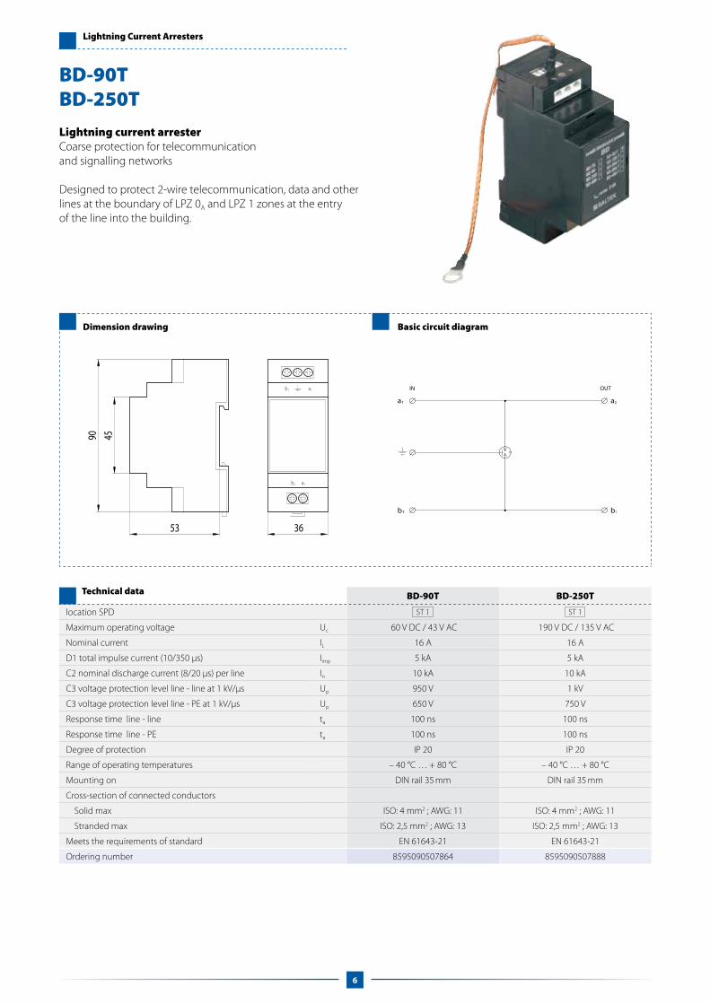
Lightning current arrester Coarse protection for telecommunication and signalling networks
Designed to protect 2-wire telecommunication, data and other lines at the boundary of LPZ 0A and LPZ 1 zones at the entry of the line into the building.
BD-90T BD-250T
location SPD ST 1 ST 1
Maximum operating voltage Uc 60 V DC / 43 V AC 190 V DC / 135 V AC
Nominal current IL 16 A 16 A
D1 total impulse current (10/350 μs) Iimp 5 kA 5 kA
C2 nominal discharge current (8/20 μs) per line In 10 kA 10 kA
C3 voltage protection level line - line at 1 kV/μs Up 950 V 1 kV
C3 voltage protection level line - PE at 1 kV/μs Up 650 V 750 V
Response time line - line ta 100 ns 100 ns
Response time line - PE ta 100 ns 100 ns
Degree of protection IP 20 IP 20
Range of operating temperatures – 40 °C … + 80 °C – 40 °C … + 80 °C
Mounting on DIN rail 35 mm DIN rail 35 mm
Cross-section of connected conductors
Solid max ISO: 4 mm2 ; AWG: 11 ISO: 4 mm2 ; AWG: 11
Stranded max ISO: 2,5 mm2 ; AWG: 13 ISO: 2,5 mm2 ; AWG: 13
Meets the requirements of standard EN 61643-21 EN 61643-21
Ordering number 8595090507864 8595090507888
Technical data
BD-90TBD-250T
6

Lightning Current Arresters
Dimension drawing Basic circuit diagram
Lightning current arresterCombined with coarse and fine surge protection for telecommunication and signalling networks.
Designed to protect 2-wire telecommunication, data and other lines and the communication interface of measurement and control, electronic security and fire detection systems, etc. at the boundary of LPZ 0A–LPZ 1 zones and higher. It should be installed directly before the protected equipment. The lightning current arrester and coarse surge protection prevent longitudinal overvoltage (core – earth). A three-level combination of lightning current arrester and coarse and fine surge protection prevents lateral overvoltage (core – core).
BDG-06 BDG-12 BDG-24 BDG-48 BDG-230
location SPD ST 1+2+3 ST 1+2+3 ST 1+2+3 ST 1+2+3 ST 1+2+3
Nominal voltage Un 6 V DC 12 V DC 24 V DC 48 V DC 230 V DC
Maximum operating voltage Uc 8,1 V DC / 5,7 V AC 14,5 V DC / 10,2 V AC 29,1 V DC / 20,6 V AC 50,2 V DC / 35,6 V AC 243 V DC / 172 V AC
Nominal current IL 1 A 1 A 1 A 1 A 1 A
D1 total impulse current (10/350 μs) Iimp 5 kA 5 kA 5 kA 5 kA 5 kA
C2 nominal discharge current (8/20 μs) per line In 10 kA 10 kA 10 kA 10 kA 10 kA
C2 voltage protection level line - line at In UP 25 V 40 V 65 V 95 V 350 V
C2 voltage protection level line - PE at In Up 600 V 600 V 600 V 700 V 650 V
C3 voltage protection level line - line at 1 kV/μs Up 14 V 22 V 40 V 75 V 350 V
C3 voltage protection level line - PE at 1 kV/μs Up 450 V 450 V 450 V 450 V 750 V
Series resistance per line R 1 Ω 1 Ω 1 Ω 1 Ω 1 Ω
Threshold frequency line - line fG 1,6 MHz 3 MHz 6,7 MHz 10,5 MHz 36 MHz
Response time line - line ta 1 ns 1 ns 1 ns 1 ns 1 ns
response time line - PE ta 100 ns 100 ns 100 ns 100 ns 100 ns
Degree of protection IP 20 IP 20 IP 20 IP 20 IP 20
Range of operating temperatures – 40 °C … +80 °C – 40 °C … +80 °C – 40 °C … +80 °C – 40 °C … +80 °C – 40 °C … +80 °C
Mounting on DIN rail 35 mm DIN rail 35 mm DIN rail 35 mm DIN rail 35 mm DIN rail 35 mm
Cross-section of connected conductors
Solid max ISO: 4 mm2 ; AWG: 11 ISO: 4 mm2 ; AWG: 11 ISO: 4 mm2 ; AWG: 11 ISO: 4 mm2 ; AWG: 11 ISO: 4 mm2 ; AWG: 11
Stranded max ISO: 2,5 mm2 ; AWG: 13 ISO: 2,5 mm2 ; AWG: 13 ISO: 2,5 mm2 ; AWG: 13 ISO: 2,5 mm2 ; AWG: 13 ISO: 2,5 mm2 ; AWG: 13
Tightening torque 0,6 Nm 0,6 Nm 0,6 Nm 0,6 Nm 0,6 Nm
Meets the requirements of standard EN 61643-21 EN 61643-21 EN 61643-21 EN 61643-21 EN 61643-21
Ordering number 8595090521853 8595090521990 8595090522003 8595090527404 8595090530770
Technical data
BDG-06BDG-12BDG-24BDG-48BDG-230
7

Lightning Current Arresters
Dimension drawing Basic circuit diagram
Lightning current arresterCombined with coarse and fine surge protection for telecommunication and signalling networks.
Designed to protect 2-wire telecommunication, data and other lines and the communication interface of measurement and control, electronic security and fire detection systems, etc. at the boundary of LPZ 0A–LPZ 1 zones and higher. It should be installed directly before the protected equipment. Longitudinal overvoltage (core – earth) and lateral overvoltage (core – core) are prevented by a three-level combination of lightning current arrester, coarse and fine surge protection.
BDM-06 BDM-12 BDM-24 BDM-48 BDM-230
Location SPD ST 1+2+3 ST 1+2+3 ST 1+2+3 ST 1+2+3 ST 1+2+3
Nominal voltage Un 6 V DC 12 V DC 24 V DC 48 V DC 230 V DC
Maximum operating voltage Uc 8,1 V DC / 5,7 V AC 14,5 V DC / 10,2 V AC 26,8 V DC / 19 V AC 50,2 V DC / 35,6 V AC 243 V DC / 172 V AC
Nominal current IL 1 A 1 A 1 A 1 A 1 A
D1 total impulse current (10/350 μs) Iimp 5 kA 5 kA 5 kA 5 kA 5 kA
C2 nominal discharge current (8/20 μs) per line In 10 kA 10 kA 10 kA 10 kA 10 kA
C2 voltage protection level line - line at In UP 25 V 40 V 65 V 95 V 380 V
C2 voltage protection level line - PE at In Up 25 V 40 V 65 V 95 V 380 V
C3 voltage protection level line - line at 1 kV/μs Up 14 V 22 V 40 V 75 V 350 V
C3 voltage protection level line - PE at 1 kV/μs Up 14 V 22 V 40 V 75 V 350 V
Series resistance per line R 1 Ω 1 Ω 1 Ω 1 Ω 1 Ω
Threshold frequency line - line fG 4 MHz 11 MHz 17 MHz 24 MHz 53 MHz
Response time line - line ta 1 ns 1 ns 1 ns 1 ns 1 ns
Response time line - PE ta 1 ns 1 ns 1 ns 1 ns 1 ns
Degree of protection IP 20 IP 20 IP 20 IP 20 IP 20
Range of operating temperatures – 40 °C … + 80 °C – 40 °C … + 80 °C – 40 °C … + 80 °C – 40 °C … + 80 °C – 40 °C … + 80 °C
Mounting on DIN rail 35 mm DIN rail 35 mm DIN rail 35 mm DIN rail 35 mm DIN rail 35 mm
Cross-section of connected conductors
Solid max ISO: 4 mm2 ; AWG: 11 ISO: 4 mm2 ; AWG: 11 ISO: 4 mm2 ; AWG: 11 ISO: 4 mm2 ; AWG: 11 ISO: 4 mm2 ; AWG: 11
Stranded max ISO: 2,5 mm2 ; AWG: 13 ISO: 2,5 mm2 ; AWG: 13 ISO: 2,5 mm2 ; AWG: 13 ISO: 2,5 mm2 ; AWG: 13 ISO: 2,5 mm2 ; AWG: 13
Meets the requirements of standard EN 61643-21 EN 61643-21 EN 61643-21 EN 61643-21 EN 61643-21
Ordering number 8595090522027 8595090522034 8595090522041 8595090522058 8595090530787
Technical data
BDM-06BDM-12BDM-24BDM-48BDM-230
8

Surge Arresters
Dimension drawing Basic circuit diagram
DM-006/1-RSDM-012/1-RSDM-024/1-RSDM-048/1-RSDM-060/1-RSDM-110/1-RS
Combination of coarse and fine surge protection for telecommunication and signalling networks coupling impedance (R)
Designed to protect 2-wire telecommunication, data and other lines and the communication interface of measurement and control, electronic security and fire detection systems, etc. against pulse overvoltage. Longitudinal overvoltage (core – earth) and lateral overvoltage (core – core) are prevented by a two-level combination of coarse and fine surge protection.
PE
B1
A1
B2
A2
SH SH
PE
B1
A1
SH
A2
B2
SH
*) **)
*) – thickness without lid**) – thickness with lid
DM-006/1-RS DM-012/1-RS DM-024/1-RS DM-048/1-RS DM-060/1-RS DM-110/1-RSLocation SPD ST 2+3 ST 2+3 ST 2+3 ST 2+3 ST 2+3 ST 2+3
Nominal voltage Un 6 V DC 12 V DC 24 V DC 48 V DC 60 V DC 110 V DCMaximum operating voltage Uc 8,5 V DC / 6 V AC 16 V DC / 11 V AC 36 V DC / 25 V AC 51 V DC / 36 V AC 64 V DC / 45 V AC 120 V DC / 85 V ACNominal current @ 25 °C IL 500 mA 500 mA 500 mA 500 mA 500 mA 500 mA C2 nominal discharge current (8/20 μs) per line In 5 kA 5 kA 5 kA 5 kA 5 kA 5 kAC2 total discharge current (8/20 μs) I total 10 kA 10 kA 10 kA 10 kA 10 kA 10 kAC2 voltage protection level line - line at In Up 18 V 28 V 50 V 80 V 100 V 210 VC2 voltage protection level line - PE at In Up 30 V 40 V 65 V 95 V 120 V 230 VC3 voltage protection level line - line at 1 kV/μs Up 12 V 20 V 45 V 65 V 85 V 170 VC3 voltage protection level line - PE at 1 kV/μs Up 15 V 20 V 45 V 65 V 85 V 170 VSeries resistance per line R 1,6 Ω 1,6 Ω 1,6 Ω 1,6 Ω 1,6 Ω 1,6 Ω Threshold frequency line - line fG 1 MHz 2 MHz 4 MHz 5 MHz 6,5 MHz 10 MHz Response time line - line ta 1 ns 1 ns 1 ns 1 ns 1 ns 1 nsResponse time line - PE ta 1 ns 1 ns 1 ns 1 ns 1 ns 1 nsDegree of protection IP 20 IP 20 IP 20 IP 20 IP 20 IP 20Range of operating temperatures -40 °C … +70 °C -40 °C … +70 °C -40 °C … +70 °C -40 °C … +70 °C -40 °C … +70 °C -40 °C … +70 °CMounting on DIN rail 35 mm DIN rail 35 mm DIN rail 35 mm DIN rail 35 mm DIN rail 35 mm DIN rail 35 mmCross-section of connected conductors Solid max. ISO: 4 mm2 ; AWG: 11 Stranded max. ISO: 2,5 mm2 ; AWG: 13Meets the requirements of standard EN 61643-21 +A1, A2Ordering number 8595090551409 8595090551416 8595090551423 8595090551430 8595090551294 8595090551300
Note: lid is included
Technical data
9

Surge Arresters
Dimension drawing Basic circuit diagram
DMG-006/1-RSDMG-012/1-RSDMG-024/1-RSDMG-048/1-RSDMG-060/1-RSDMG-110/1-RS
Combination of coarse and fine surge protection for telecommunication and signalling networks
Designed to protect 2-wire telecommunication, data and other lines and the communication interface of measurement and control, electronic security and fire detection systems, etc. against pulse overvoltage. Longitudinal overvoltage (core – earth) is prevented by coarse surge protection. Lateral overvoltage (core – core) is prevented by a two-level combination of coarse and fine surge protection.
PE
B1
A1
B2
A2
SH SH
DMG-006/1-RS DMG-012/1-RS DMG-024/1-RS DMG-048/1-RS DMG-060/1-RS DMG-110/1-RS Location SPD ST 2+3 ST 2+3 ST 2+3 ST 2+3 ST 2+3 ST 2+3
Nominal voltage Un 6 V DC 12 V DC 24 V DC 48 V DC 60 V DC 110 V DCMaximum operating voltage Uc 8,5 V DC / 6 V AC 16 V DC / 11 V AC 36 V DC / 25 V AC 51 V DC / 36 V AC 64 V DC / 45 V AC 120 V DC / 85 V ACNominal current @ 25 °C IL 500 mA 500 mA 500 mA 500 mA 500 mA 500 mA C2 nominal discharge current (8/20 μs) per core In 5 kA 5 kA 5 kA 5 kA 5 kA 5 kAC2 total discharge current (8/20 μs) I total 10 kA 10 kA 10 kA 10 kA 10 kA 10 kAC2 voltage protection level core - core at In Up 18 V 28 V 50 V 80 V 100 V 210 VC2 voltage protection level core - PE at In Up 350 V 350 V 350 V 350 V 350 V 350 VC3 voltage protection level core - core at 1 kV/μs Up 12 V 20 V 45 V 65 V 85 V 170 VC3 voltage protection level core - PE at 1 kV/μs Up 500 V 500 V 500 V 500 V 500 V 500 VSeries resistance per core R 1,6 Ω 1,6 Ω 1,6 Ω 1,6 Ω 1,6 Ω 1,6 Ω Threshold frequency core - core fG 1 MHz 2 MHz 4 MHz 5 MHz 6,5 MHz 10 MHz Response time core - core ta 1 ns 1 ns 1 ns 1 ns 1 ns 1 nsResponse time core - PE ta 100 ns 100 ns 100 ns 100 ns 100 ns 100 nsDegree of protection IP 20 IP 20 IP 20 IP 20 IP 20 IP 20Range of operating temperatures -40 °C … +70 °C -40 °C … +70 °C -40 °C … +70 °C -40 °C … +70 °C -40 °C … +70 °C -40 °C … +70 °CMounting on DIN rail 35 mm DIN rail 35 mm DIN rail 35 mm DIN rail 35 mm DIN rail 35 mm DIN rail 35 mmCross-section of connected conductors Solid max. ISO: 4 mm2 ; AWG: 11 Stranded max. ISO: 2,5 mm2 ; AWG: 13Meets the requirements of standard EN 61643-21 +A1, A2Ordering number 8595090551324 8595090551331 8595090551348 8595090551355 8595090551362 8595090551379
Note: lid is included
Technical data
10
PE
B1
A1
SH
A2
B2
SH
*) **)
*) – thickness without lid**) – thickness with lid

Surge Arresters
Dimension drawing Basic circuit diagram
Combination of coarse and fine surge protection for high-frequency telecommunication and signalling networks
Designed to protect 2-wire telecommunication, data and other lines and the communication interface of measurement and control, electronic security and fire detection systems, etc. against pulse overvoltage. Longitudinal overvoltage (core – earth) is prevented by coarse surge protection. Lateral overvoltage (core – core) is prevented by a two-level combination of coarse and fine surge protection.
DMHF-006/1-RS DMHF-015/1-RSLocation SPD ST 2+3 ST 2+3
Nominal voltage Un 6 V DC 15 V DCMaximum operating voltage Uc 8,5 V DC / 6 V AC 22 V DC / 15 V ACNominal current @ 25 °C IL 500 mA 500 mA C2 nominal discharge current (8/20 μs) per core In 5 kA 5 kAC2 total discharge current (8/20 μs) I total 10 kA 10 kAC2 voltage protection level core - core at In Up 26 V 36 VC2 voltage protection level core - PE at In Up 350 V 350 VC3 voltage protection level core - core at 1 kV/μs Up 14 V 28 VC3 voltage protection level core - PE at 1 kV/μs Up 500 V 500 VSeries resistance per core R 1,6 Ω 1,6 Ω Threshold frequency core - core fG 70 MHz 70 MHz Response time core - core ta 1 ns 1 nsResponse time core - PE ta 1 ns 1 nsDegree of protection IP 20 IP 20Range of operating temperatures -40 °C … +70 °C -40 °C … +70 °CMounting on DIN rail 35 mm DIN rail 35 mmCross-section of connected conductors Solid max. ISO: 4 mm2 ; AWG: 11 ISO: 4 mm2 ; AWG: 11 Stranded max. ISO: 2,5 mm2 ; AWG: 13 ISO: 2,5 mm2 ; AWG: 13Meets the requirements of standard EN 61643-21 +A1, A2 EN 61643-21 +A1, A2Ordering number 8595090551386 8595090551393
Technical data
DMHF-006/1-RS DMHF-015/1-RS
PE
B1
A1
B2
A2
SH SH
PE
B1
A1
SH
A2
B2
SH
*) **)
*) – thickness without lid**) – thickness with lid
11

Surge Arresters
Dimension drawing Basic circuit diagram
Combination of coarse and fine surge protection
Designed to protect single-wire telecommunication, data and other lines and the communication interface of measurement and control, electronic security and fire detection systems, etc. against pulse overvoltage. Longitudinal overvoltage (core - earth) is prevented by a two-level combination of coarse and fine surge protection.
DMJ-012/2-RSDMJ-024/2-RSDMJ-048/2-RSDMJ-060/2-RSDMJ-110/2-RS
PE
B1
A1
B2
A2
SH SH
DMJ-012/1-RS DMJ-024/1-RS DMJ-048/1-RS DMJ-060/1-RS DMJ-110/1-RS Location SPD ST 2+3 ST 2+3 ST 2+3 ST 2+3 ST 2+3
Nominal voltage Un 12 V DC 24 V DC 48 V DC 60 V DC 110 V DCMaximum operating voltage Uc 16 V DC / 11 V AC 36 V DC / 25 V AC 51 V DC / 36 V AC 64 V DC / 45 V AC 120 V DC / 85 V ACNominal load current @ 25 °C IL 500 mA 500 mA 500 mA 500 mA 500 mA C2 nominal discharge current (8/20 μs) line In 5 kA 5 kA 5 kA 5 kA 5 kAC2 total discharge current (8/20 μs) I total 10 kA 10 kA 10 kA 10 kA 10 kAC2 voltage protection level line – PE at In Up 40 V 65 V 95 V 120 V 230 VC3 voltage protection level line – PE at 1 kV/μs Up 20 V 45 V 65 V 85 V 170 VSeries resistance per line R R 1,6 Ω 1,6 Ω 1,6 Ω 1,6 Ω 1,6 Ω Threshold frequency line - line fG 2 MHz 4 MHz 5 MHz 6,5 MHz 10 MHz Response time - PE ta 1 ns 1 ns 1 ns 1 ns 1 nsDegree of protection IP 20 IP 20 IP 20 IP 20 IP 20Range of operating temperatures -40 °C … +70 °C -40 °C … +70 °C -40 °C … +70 °C -40 °C … +70 °C -40 °C … +70 °CMounting on DIN rail 35 mm DIN rail 35 mm DIN rail 35 mm DIN rail 35 mm DIN rail 35 mmCross-section of connected conductors Solid min/max ISO: 4 mm2 ; AWG: 11 Stranded min/max ISO: 2,5 mm2 ; AWG: 13Meets the requirements of standard EN 61643-21 +A1, A2Ordering number 8595090551447 8595090551454 8595090551317 8595090551461 8595090551478
Note: lid is included
Technical data
12
PE
B1
A1
SH
A2
B2
SH
*) **)
*) – thickness without lid**) – thickness with lid

Surge Arresters
Dimension drawing Basic circuit diagram
Surge arrester for measurement and controlFor LSA-PLUS disconnection module
Combination of coarse and fine protection designed to protect data lines.
CLSA-6CLSA-12CLSA-24CLSA-48
a1 a2
b1 b2
CLSA-6 CLSA-12 CLSA-24 CLSA-48
Location SPD ST 2+3 ST 2+3 ST 2+3 ST 2+3
Maximum operating voltage Uc 8,5 V DC / 6 V AC 16 V DC / 11 V AC 36 V DC / 25 V AC 51 V DC / 36 V AC
Nominal current @ 25 °C IL 500 mA 500 mA 500 mA 500 mA
C2 nominal discharge current (8/20 μs) per line In 5 kA 5 kA 5 kA 5 kA
C2 total discharge current (8/20 μs) Itotal 10 kA 10 kA 10 kA 10 kA
C2 voltage protection level line – PE at In Up 400 V 400 V 400 V 400 V
C3 voltage protection level line – line at 1 kV/μs Up 13 V 21 V 48 V 65 V
C3 voltage protection level line – PE at 1 kV/μs Up 350 V 350 V 350 V 350 V
Series resistance per line R 1,6 Ω 1,6 Ω 1,6 Ω 1,6 Ω
Threshold frequency fG 1,5 MHz 2,5 MHz 4 MHz 6,5 MHz
Response time line - line ta 1 ns 1 ns 1 ns 1 ns
Response time line - PE ta 100 ns 100 ns 100 ns 100 ns
Degree of protection IP 20 IP 20 IP 20 IP 20
Range of operating temperatures -40 °C … +70 °C -40 °C … +70 °C -40 °C … +70 °C -40 °C … +70 °C
Mounting on LSA – PLUS (Krone) LSA – PLUS (Krone) LSA – PLUS (Krone) LSA – PLUS (Krone)
Meets the requirements of standard EN 61643-21 + A1, A2
Ordering number 8595090551690 8595090551706 8595090551713 8595090551720
Technical data
13

Surge Arresters
Dimension drawing Basic circuit diagram
Surge arresters for telecommuncation, measurement and controlFor LSA-PLUS disconnection module
Combination of coarse and fine protection designed toprotect data lines with high speed rates.
CLSA-HF6 CLSA-DSL
Location SPD ST 2+3 ST 2+3
Maximum operating voltage Uc 8,5 V DC / 6 V AC 170 V DC / 120 V AC
Nominal current @ 25 °C IL 500 mA 500 mA
C2 nominal discharge current (8/20 μs) per line In 5 kA 5 kA
C2 total discharge current (8/20 μs) Itotal 10 kA 10 kA
C2 voltage protection level line – line at In Up 32 V 280 V
C2 voltage protection level line – PE at In Up 350 V 350 V
C3 voltage protection level line – line at 1 kV/μs Up 15 V 230 V
C3 voltage protection level line – PE at 1 kV/μs Up 350 V 400 V
Series resistance per line R 1,6 Ω 1,6 Ω
Threshold frequency fG 55 MHz 65 MHz
Response time line - line ta 1 ns 1 ns
Response time line - PE ta 100 ns 100 ns
Degree of protection IP 20 IP 20
Range of operating temperatures -40 °C … +70 °C -40 °C … +70 °C
Mounting on LSA – PLUS (Krone) LSA – PLUS (Krone)
Meets the requirements of standard EN 61643-21 + A1, A2 EN 61643-21 + A1, A2
Ordering number 8595090551751 8595090551768
Technical data
CLSA-HF6 CLSA-DSL
14

Surge Arresters
Dimension drawing Basic circuit diagram
Combination of coarse and fine surge protection for telecommunication and signalling networks z = coupling impedance (R – resistance, L or L2 – inductivity)
Designed to protect 2-wire telecommunication, data and other lines and the communication interface of measurement and control, electronic security and fire detection systems, etc. against pulse overvoltage. Longitudinal overvoltage (core–earth) and lateral overvoltage (core – core) are prevented by a two-level combination of coarse and fine surge protection.
DM-006/1 z DJ DM-012/1 z DJ DM-024/1 z DJ DM-048/1 z DJ
Location SPD ST 2+3 ST 2+3 ST 2+3 ST 2+3
Nominal voltage Un 6 V DC 12 V DC 24 V DC 48 V DC
Maximum operating voltage Uc 8,1 V DC / 5,7 V AC 14,5 V DC / 10,2 V AC 29,1 V DC / 20,6 V AC 50,2 V DC / 35,6 V AC
Nominal current R/L/L2 IL 60 mA / 370 mA / 2A 60 mA / 370 mA / 2A 60 mA / 370 mA / 2A 60 mA / 370 mA / 2A
C2 nominal discharge current (8/20 μs) per line In 10 kA 10 kA 10 kA 10 kA
C2 voltage protection level line - line at In Up 25 V 35 V 50 V 80 V
C2 voltage protection level line - PE at In Up 20 V 35 V 50 V 80 V
C3 voltage protection level line - line at 1 kV/μs Up 12 V 20 V 40 V 70 V
C3 voltage protection level line - PE at 1 kV/μs Up 15 V 30 V 48 V 75 V
Series resistance per line R/L/L2 R 6,8 Ω / 100 μH / 25 μH 6,8 Ω / 100 μH / 25 μH 6,8 Ω / 100 μH / 25 μH 6,8 Ω / 100 μH / 25 μH
Threshold frequency line - line R/L/L2 fG 1 MHz / 160 kHz / 550 kHz 1,7 MHz / 160 kHz / 600 kHz 3,4 MHz / 160 kHz / 600 kHz 7 MHz / 160 kHz / 600 kHz
Response time line - line ta 1 ns 1 ns 1 ns 1 ns
Response time line - PE ta 1 ns 1 ns 1 ns 1 ns
Degree of protection IP 20 IP 20 IP 20 IP 20
Range of operating temperatures – 40 °C … + 80 °C – 40 °C … + 80 °C – 40 °C … + 80 °C – 40 °C … + 80 °C
Mounting on DIN rail 35 mm DIN rail 35 mm DIN rail 35 mm DIN rail 35 mm
Cross-section of connected conductors
Solid max. ISO: 4 mm2 ; AWG: 11 ISO: 4 mm2 ; AWG: 11 ISO: 4 mm2 ; AWG: 11 ISO: 4 mm2 ; AWG: 11
Stranded max. ISO: 2,5 mm2 ; AWG: 13 ISO: 2,5 mm2 ; AWG: 13 ISO: 2,5 mm2 ; AWG: 13 ISO: 2,5 mm2 ; AWG: 13
Meets the requirements of standard EN 61643-21 EN 61643-21 EN 61643-21 EN 61643-21
Ordering number
DM-xxx/1 R DJ 8595090509301 8595090509318 8595090509325 8595090509332
DM-xxx/1 L DJ 8595090515579 8595090513520 8595090512370 8595090513537
DM-xxx/1 L2 DJ 8595090513322 8595090513315 8595090513339 8595090513346
Technical data
DM-006/1 z DJDM-012/1 z DJDM-024/1 z DJDM-048/1 z DJ
15

DM-006/1 3z DJ DM-012/1 3z DJ DM-024/1 3z DJ DM-048/1 3z DJ
Location SPD ST 2+3 ST 2+3 ST 2+3 ST 2+3
Nominal voltage Un 6 V DC 12V DC 24 V DC 48 V DC
Maximum operating voltage Uc 8,1 V DC / 5,7 V AC 14,5 V DC / 10,2 V AC 29,1 V DC / 20,6 V AC 50,2 V DC / 35,6 V AC
Nominal current R/L IL 60 mA / 370 mA 60 mA / 370 mA 60 mA / 370 mA 60 mA / 370 mA
C2 nominal discharge current (8/20 μs) per line In 10 kA 10 kA 10 kA 10 kA
C2 voltage protection level line - line (COM) at In Up 25 V 35 V 50 V 80 V
C2 voltage protection level linka (COM,SH) – PE at In Up 350 V 350 V 350 V 350 V
C3 voltage protection level line - line (COM) at 1 kV/μs Up 12 V 20 V 40 V 65 V
C3 voltage protection level linka (COM,SH) – PE at 1 kV/μs Up 650 V 650 V 650 V 650 V
Series resistance per line R/L R 6,8 Ω / 100 μH 6,8 Ω / 100 μH 6,8 Ω / 100 μH 6,8 Ω / 100 μH
Threshold frequency line - line R/L fG 1 MHz / 160 kHz 1,7 MHz / 160 kHz 3,4 MHz / 160 kHz 7 MHz / 160 kHz
Response time line - line ta 1 ns 1 ns 1 ns 1 ns
Response time line - PE ta 100 ns 100 ns 100 ns 100 ns
Degree of protection IP 20 IP 20 IP 20 IP 20
Range of operating temperatures – 40 °C … + 80 °C – 40 °C … + 80 °C – 40 °C … + 80 °C – 40 °C … + 80 °C
Mounting on DIN rail 35 mm DIN rail 35 mm DIN rail 35 mm DIN rail 35 mm
Cross-section of connected conductors
Solid max. ISO: 4 mm2 ; AWG: 11 ISO: 4 mm2 ; AWG: 11 ISO: 4 mm2 ; AWG: 11 ISO: 4 mm2 ; AWG: 11
Stranded max. ISO: 2,5 mm2 ; AWG: 13 ISO: 2,5 mm2 ; AWG: 13 ISO: 2,5 mm2 ; AWG: 13 ISO: 2,5 mm2 ; AWG: 13
Max. Tightening torque 0,6 Nm 0,6 Nm 0,6 Nm 0,6 Nm
Meets the requirements of standard EN 61643-21 EN 61643-21 EN 61643-21 EN 61643-21
Ordering numberDM-xxx/1 3R DJ 8595090513506 8595090513490 8595090512349 8595090513483
DM-xxx/1 3L DJ 8595090514022 8595090520948 8595090515197 8595090516484
Technical data
Dimension drawing Basic circuit diagram
Surge Arresters
Combination of coarse and fine surge protection for telecommunication and signalling networks z = coupling impedance (R – resistance, L or L2 – inductivity)
Designed to protect 3-wire telecommunication, data and other lines and the communication interface of measurement and control, electronic security and fire detection systems, etc., particularly RS 485, RS 422 and RS 232 interfaces, against pulse overvoltage. Longitudinal overvoltage (core–earth) is prevented by coarse surge protection. Lateral overvoltage (core–core) is prevented by a two-level combination of coarse and fine surge protection.
DM-006/1 3z DJDM-012/1 3z DJDM-024/1 3z DJDM-048/1 3z DJ
16

DM-006/1 4R DJ DM-012/1 4R DJ DM-024/1 4R DJ DM-048/1 4R DJ
Location SPD ST 2+3 ST 2+3 ST 2+3 ST 2+3
Nominal voltage Un 6 V DC 12 V DC 24 V DC 48 V DC
Maximum operating voltage Uc 8,1 V DC / 5,7 V AC 14,5 V DC / 10,2 V AC 29,1 V DC / 20,6 V AC 50,2 V DC / 35,6 V AC
Nominal current IL 60 mA 60 mA 60 mA 60 mA
C2 nominal discharge current (8/20 μs) per line In 10 kA 10 kA 10 kA 10 kA
C2 voltage protection level line - line at In Up 25 V 35 V 50 V 80 V
C2 voltage protection level line - PE at In Up 350 V 350 V 350 V 350 V
C3 voltage protection level line - line at 1 kV/μs Up 12 V 20 V 40 V 65 V
C3 voltage protection level line - PE at 1 kV/μs Up 650 V 650 V 650 V 650 V
Series resistance per line R 6,8 Ω 6,8 Ω 6,8 Ω 6,8 Ω
Threshold frequency line - line fG 1 MHz 1,7 MHz 3,4 MHz 7 MHz
Response time line - line ta 1 ns 1 ns 1 ns 1 ns
Response time line - PE ta 100 ns 100 ns 100 ns 100 ns
Degree of protection IP 20 IP 20 IP 20 IP 20
Range of operating temperatures – 40 °C … + 80 °C – 40 °C … + 80 °C – 40 °C … + 80 °C – 40 °C … + 80 °C
Mounting on DIN rail 35 mm DIN rail 35 mm DIN rail 35 mm DIN rail 35 mm
Cross-section of connected conductors
Solid max. ISO: 4 mm2 ; AWG: 11 ISO: 4 mm2 ; AWG: 11 ISO: 4 mm2 ; AWG: 11 ISO: 4 mm2 ; AWG: 11
Stranded max. ISO: 2,5 mm2 ; AWG: 13 ISO: 2,5 mm2 ; AWG: 13 ISO: 2,5 mm2 ; AWG: 13 ISO: 2,5 mm2 ; AWG: 13
Max. Tightening torque 0,6 Nm 0,6 Nm 0,6 Nm 0,6 Nm
Meets the requirements of standard EN 61643-21 EN 61643-21 EN 61643-21; EN 61643-21
Ordering number 8595090516750 8595090516897 8595090513575 8595090519775
Technical data
Surge Arresters
Dimension drawing Basic circuit diagram
Combination of coarse and fine surge protection for telecommunication and signalling networks
Designed to protect 4-wire telecommunication, data and other lines and the communication interface of measurement and control, electronic security and fire detection systems, etc., particularly RS 485, RS 422 and RS 232 interfaces, against pulse overvoltage. Longitudinal overvoltage (core–earth) is prevented by coarse surge protection. Lateral overvoltage (core–core) is prevented by a two-level combination of coarse and fine surge protection.
DM-006/1 4R DJDM-012/1 4R DJDM-024/1 4R DJDM-048/1 4R DJ
17

Surge Arresters
Dimension drawing Basic circuit diagram
Combination of coarse and fine surge protection for the PROFIBUS industrial bus-bar system.
Designed to protect line and communication interfaces of the PROFIBUS industrial bus-bar system. Longitudinal overvoltage (core–earth) is prevented by coarse surge protection. Lateral overvoltage (core–core) is prevented by a two-level combination of coarse and fine surge protection. Also, cable shielding is protected.
DM-PROFIBUS 5 V DM-PROFIBUS 24 V
Location SPD ST 2+3 ST 2+3
Nominal voltage Un 5 V DC 24 V DC
Maximum operating voltage Uc 8,1 V DC/5,7 V AC 29,1 V DC / 20,6 V AC
Nominal current IL 60 mA 60 mA
C2 nominal discharge current (8/20 μs) per line In 10 kA 10 kA
C2 voltage protection level line - line (COM) at In UP 150 V 300 V
C2 voltage protection level COM (SH) – PE at ln Up 350 V 350 V
C3 voltage protection level line - line (COM) at 1 kV/μs Up 40 V 40 V
C3 voltage protection level COM (SH) – PE at 1 kV/μs Up 650 V 650 V
Series resistance per line R 1 Ω 1 Ω
Threshold frequency line - line fG 100 MHz 100 MHz
Response time line - line (COM) ta 1 ns 1 ns
Response time COM (SH) – PE ta 100 ns 100 ns
Degree of protection IP 20 IP 20
Range of operating temperatures – 40 °C … + 80 °C – 40 °C … + 80 °C
Mounting on DIN rail 35 mm DIN rail 35 mm
Cross-section of connected conductors
Solid max ISO: 4 mm2 ; AWG: 11 ISO: 4 mm2 ; AWG: 11
Stranded max ISO: 2,5 mm2 ; AWG: 13 ISO: 2,5 mm2 ; AWG: 13
Meets the requirements of standard EN 61643-21 EN 61643-21
Ordering number 8595090515319 8595090516736
Technical data
DM-PROFIBUS 5 VDM-PROFIBUS 24 V
18
Surge Arresters
Dimension drawing Basic circuit diagram
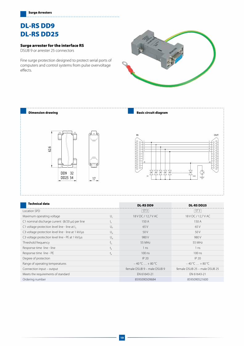
Surge arrester for the interface RSDSUB 9 or arrester 25 connectors
Fine surge protection designed to protect serial ports of computers and control systems from pulse overvoltage effects.
DL-RS DD9 DL-RS DD25
Location SPD ST 3 ST 3
Maximum operating voltage Uc 18 V DC / 12,7 V AC 18 V DC / 12,7 V AC
C1 nominal discharge current (8/20 μs) per line In 150 A 150 A
C1 voltage protection level line - line at In UP 65 V 65 V
C3 voltage protection level line - line at 1 kV/μs Up 50 V 50 V
C3 voltage protection level line - PE at 1 kV/μs Up 980 V 980 V
Threshold frequency fG 55 MHz 55 MHz
Response time line - line ta 1 ns 1 ns
Response time line - PE ta 100 ns 100 ns
Degree of protection IP 20 IP 20
Range of operating temperatures – 40 °C … + 80 °C – 40 °C … + 80 °C
Connection input – output female DSUB 9 – male DSUB 9 female DSUB 25 – male DSUB 25
Meets the requirements of standard EN 61643-21 EN 61643-21
Ordering number 8595090509684 8595090521600
Technical data
DL-RS DD9DL-RS DD25
19

Surge Arresters
Dimension drawing/ Basic circuit diagram
DS-B090-RSDS-B240-RSDS-V075-RSDS-V130-RSDS-D012-RSDS-D024-RS
a1
a2
PE
a1
b1
a2
b2
a2
b2
a1
b1
DS-Bxxx-RS DS-Vxxx-RS DS-Dxxx-RS
DS-B090-RS DS-B240-RS DS-V075-RS DS-V130-RS DS-D012-RS DS-D024-RS
Location SPD ST 2 ST 2 ST 2 ST 2 ST 3 ST 3
Maximum operating voltage Uc 70 V DC/50 V AC 180 V DC/127 V AC 100 V DC/75 V AC 180 V DC/140 V AC 14,5 V DC/10,2 V AC 29,1 V DC/20,6 V AC
Nominal current @ 25 °C IL 500 mA 500 mA 500 mA 500 mA 500 mA 500 mA
C2 nominal discharge current (8/20 μs) per line In 10 kA 10 kA 6 kA 6 kA 0,3 kA 0,3 kA
C2 voltage protection level line - PE at In Up — — 310 V 530 V 25 V 48 V
C3 voltage protection level line - PE ati 1 kV/μs Up 550 V 600 V — — — —
Responze time line - PE ta 100 ns 100 ns 25 ns 25 ns 1 ns 1 ns
Degree of protection IP 20 IP 20 IP 20 IP 20 IP 20 IP 20
Range of operating temperatures –40 ... +70 °C –40 ... +70 °C –40 ... +70 °C –40 ... +70 °C –40 ... +70 °C –40 ... +70 °C
Mounting on DIN rail DIN rail DIN rail DIN rail DIN rail DIN rail
Cross-section of connected conductors
Solid max 4 mm2 4 mm2 4 mm2 4 mm2 4 mm2 4 mm2
Stranded max 2,5 mm2 2,5 mm2 2,5 mm2 2,5 mm2 2,5 mm2 2,5 mm2
Meets the requirements of standard EN 61643-21 + A1, A2
Ordering number 8595090551485 8595090551492 8595090551508 8595090551515 8595090551522 8595090551539
Note: lid is included
Technical data
One stage surge arresterB – gas tubes, V – varistors, D – fast suppressor diods
Designed to protect telecommunication, data and others lines with common operating ground from pulse overvoltage.
*) **)
*) – thickness without lid **) – thickness with lid
20

Special Surge Arresters
Dimension drawing Basic circuit diagram
Special surge and overvoltage arresterFault signalling due to supply interruption, remote fault signalling
Designed to protect measurement and control, against pulse overvoltage effects and steady overvoltage. It is resistant to steady overvoltage from low-voltage (high-voltage) distributions.
DM-24 SECURE DM-48 SECURE
Location SPD ST 2+3 ST 2+3
Nominal voltage Un 24 V DC 48 V DCMaximum operating voltage Uc 36 V DC / 25,5 V AC 60 V DC / 42,5 V ACNominal current IL 200 mA 200 mAC2 nominal discharge current (8/20 μs) per line In 3 kA 3 kAC2 voltage protection level line - line at In UP 55 V 95 VC2 voltage protection level line - PE at In Up 650 V 1,15 kVSeries resistance per line R 3 Ω 6 ΩThreshold frequency line - line fG 1,4 MHz 1,9 MHzResponse time line - line ta 1 ns 1 nsResponse time line - PE ta 100 ns 100 nsDegree of protection IP 20 IP 20Range of operating temperatures – 40 °C … + 80 °C – 40 °C … + 80 °CMounting on DIN rail 35 mm DIN rail 35 mmCross-section of connected conductors Solid max ISO: 4 mm2 ; AWG: 11 ISO: 4 mm2 ; AWG: 11 Stranded max ISO: 2,5 mm2 ; AWG: 13 ISO: 2,5 mm2 ; AWG: 13Tightening torque 0,6 Nm 0,6 NmFault indication supply interruption, remote indication supply interruption, remote indicationRemote indication AC: 250 V/ 0,5 A; DC: 250 V / 0,1 A AC: 250 V/ 0,5 A; DC: 250 V / 0,1 ACross-section of remote indication conductors Solid max ISO: 4 mm2 ; AWG: 11 ISO: 4 mm2 ; AWG: 11 Stranded max ISO: 2,5 mm2 ; AWG: 13 ISO: 2,5 mm2 ; AWG: 13Meets the requirements of standard EN 61643-21 EN 61643-21Ordering number 8595090520689 8595090516934
Technical data
DM-24 SECUREDM-48 SECURE
11
14
12
TT
T
21

Surge Arresters
Dimension drawing Basic circuit diagram
Surge arrester for low-voltage power suppliesVisual fault signalling
Designed to protect a line of equipment connected to distributions of DC and AC supply voltage. According to the concept of lightning protection zones, it is installed at the boundary of LPZ 1–LPZ 2 zones and higher.
DP-012 DP-024 DP-048 DP-060
Location SPD ST 2 ST 2 ST 2 ST 2
Nominal voltage Un 12 V AC/DC 24 V AC/DC 48 V AC/DC 60 V AC/DC
Maximum operating voltage Uc 28 V DC / 22 V AC 44 V DC / 34 V AC 90 V DC / 70 V AC 112 V DC / 80 V ACNominal current IL 16 A 16 A 16 A 16 AC2 nominal discharge current (8/20 μs) per line In 2 kA 2 kA 2 kA 2 kAC2 voltage protection level line - line at In UP 160 V 200 V 360 V 390 VC2 voltage protection level line - PE at In Up 530 V 530 V 550 V 550 VC3 voltage protection level line - line at 1 kV/μs In 2 kA, 2 kA 2 kA, 2 kA 2 kA, 2 kA 2 kA, 2 kA
C3 voltage protection level line - PE at 1 kV/μs Uoc 4 kV, 4 kV 4 kV, 4 kV 4 kV, 4 kV 4 kV, 4 kVvoltage protection level a1–b1, a1 (b1) – PE Up 160 V, 530 V 200 V, 530 V 360 V, 550 V 390 V, 550 VMaximum current protection 16 A gL/gG or C 16 A 16 A gL/gG or C 16 A 16 A gL/gG or C 16 A 16 A gL/gG or C 16 AResponse time line - line ta 25 ns 25 ns 25 ns 25 nsResponse time line - PE ta 100 ns 100 ns 100 ns 100 nsDegree of protection IP 20 IP 20 IP 20 IP 20Range of operating temperatures – 40 °C … + 80 °C – 40 °C … + 80 °C – 40 °C … + 80 °C – 40 °C … + 80 °CMounting on DIN rail 35 mm DIN rail 35 mm DIN rail 35 mm DIN rail 35 mmCross-section of connected conductors Solid max ISO: 4 mm2 ; AWG: 11 ISO: 4 mm2 ; AWG: 11 ISO: 4 mm2 ; AWG: 11 ISO: 4 mm2 ; AWG: 11 Stranded max ISO: 2,5 mm2 ; AWG: 13 ISO: 2,5 mm2 ; AWG: 13 ISO: 2,5 mm2 ; AWG: 13 ISO: 2,5 mm2 ; AWG: 13Tightening torque 0,6 Nm 0,6 Nm 0,6 Nm 0,6 NmFault indication red indicator red indicator red indicator red indicator
Meets the requirements of standardEN 61643-21
EN 61643-11 + A11 EN 61643-21
EN 61643-11 + A11 EN 61643-21
EN 61643-11 + A11 EN 61643-21
EN 61643-11 + A11 Ordering number 8595090521877 8595090516040 8595090521884 8595090521907
Technical data
DP-012DP-024DP-048DP-060
22

Surge Arresters
Dimension drawing Basic circuit diagram
Surge arrester for telecommunicationsFor LSA-PLUS disconnection module
Combination of coarse and fine protection designed to protect telecommunication equipment including ADSL.
CLSA-TLF CLSA-ISDN
Location SPD ST 2+3 ST 2+3
Maximum operating voltage Uc 170 V DC / 120 V AC 120 V DC / 85 V AC
Nominal current @ 25 °C IL 500 mA 500 mA
C2 nominal discharge current (8/20 μs) per line In 5 kA 5 kA
C2 total discharge current (8/20 μs) Itotal 10 kA 10 kA
C2 voltage protection level line – line at In UP 310 V 220 V
C2 voltage protection level line – PE at In Up 400 V 400 V
C3 voltage protection level line – line at 1 kV/μs Up 230 V 170 V
C3 voltage protection level line – PE at 1 kV/μs Up 350 V 350 V
Series resistance per line R 1,6 Ω 1,6 Ω
Threshold frequency fG 14 MHz 16 MHz
Response time line - line ta 1 ns 1 ns
Response time line - PE ta 100 ns 100 ns
Degree of protection IP 20 IP 20
Range of operating temperatures -40 °C … +70 °C -40 °C … +70 °C
Mounting on LSA – PLUS (Krone) LSA – PLUS (Krone)
Meets the requirements of standard EN 61643-21 + A1, A2 EN 61643-21 + A1, A2
Ordering number 8595090551737 8595090551744
Technical data
CLSA-TLF CLSA-ISDN
a1 a2
b1 b2
23

Surge Arresters
Dimension drawing Basic circuit diagram
Surge arrester for telecommunicationsRJ12 connectors
Combination of coarse and fine protection designed to protect one pair of analogue lines of telecommunication equipment.
Installation by adapters for DIN rail or for screw mounting.
DL-TLF
Location SPD ST 2+3
Maximum operating voltage Uc 162 V DC / 114 V AC
Nominal current IL 60 mA
C2 nominal discharge current (8/20 μs) per line In 2,5 kA
C2 voltage protection level line - line at In UP 260 V
C2 voltage protection level line - PE at In Up 300 V
C3 voltage protection level line - line at 1 kV/μs Up 240 V
C3 voltage protection level line - PE at 1 kV/μs Up 400 V
Series resistance per line R 6,8 Ω
Threshold frequency fG 14 MHz
Response time line - line ta 1 ns
Response time line - PE ta 100 ns
Degree of protection IP 20
Range of operating temperatures – 40 °C … + 80 °C
Connection input – output RJ12 / RJ12
Mounting on DIN rail
Meets the requirements of standard EN 61643-21
Ordering number 8595090533801
Technical data
DL-TLF
24

Surge Arresters
Dimension drawing Basic circuit diagram
Surge arrester for telecommunicationsEfficient protection for ISDN
Combination of coarse and fine protection designed to protect one pair of ISDN lines of telecommunication equipment. It is installed at the boundary of LPZ 1–LPZ 2 zones and higher.
Installation by adapters for DIN rail or for screw mounting.
DL-ISDN SV
Location SPD ST 2+3
Maximum operating voltage Uc 120 V DC / 85 V AC
Nominal current IL 60 mA
C2 nominal discharge current (8/20 μs) line - line In 10 kA
C2 voltage protection level line - line at In UP 260 V
C2 voltage protection level line - PE at In Up 150 V
C3 voltage protection level line - line at 1 kV/μs Up 180 V
C3 voltage protection level line - PE at 1 kV/μs Up 500 V
Series resistance per line R 6,8 Ω
Threshold frequency fG 50 MHz
Response time line - line ta 1 ns
Response time line - PE ta 1 ns
Degree of protection IP 20
Range of operating temperatures – 40 °C … + 80 °C
Connection input – output terminals
Mounting on DIN rail
Cross-section of connected conductors ISO: 2,5 mm2 ; AWG: 13
Meets the requirements of standard EN 61643-21
Meets the requirements of standard 8595090533818
Technical data
DL-ISDN SV
25

Surge Arresters
Dimension drawing Basic circuit diagram
Surge arrester for telecommunicationsRJ45 connectors
Combination of coarse and fine protection designed to protect one pair of ISDN lines of telecommunication equipment. It is installed at the boundary of LPZ 1–LPZ 2 zones and higher.
Installation by adapters for DIN rail or for screw mounting.
DL-ISDN RJ45
Location SPD ST 2+3
Maximum operating voltage Uc 121 V DC / 86 V AC
Nominal current IL 60 mA
C2 nominal discharge current (8/20 μs) per line In 2,5 kA
C2 voltage protection level line - line at In UP 270 V
C2 voltage protection level line - PE at In Up 300 V
C3 voltage protection level line - line at 1 kV/μs Up 180 V
C3 voltage protection level line - PE at 1 kV/μs Up 400 V
Series resistance per line R 6,8 Ω
Threshold frequency fG 80 MHz
Response time line - line ta 1 ns
Response time line - PE ta 100 ns
Degree of protection IP 20
Range of operating temperatures – 40 °C … + 80 °C
Connection input – output RJ45 / RJ45
Mounting on DIN rail
Meets the requirements of standard EN 61643-21
Ordering number 8595090533825
Technical data
DL-ISDN RJ45
26

Surge Arresters
Dimension drawing Basic circuit diagram
Surge arrester for Ethernet Cat. 5econnectors RJ45
Fine surge protection designed to protect one port of Ethernet Cat. 5e. It is installed at the boundary of LPZ 2 and LPZ 3 zones, directly before the equipment.
Installation by adapters for DIN rail or for screw mounting.
DL-Cat. 5e
Location SPD ST 3
Maximum operating voltage Uc 8,5 V DC / 6 V AC
Nominal current IL 500 mA
C2 total nominal discharge current (8/20 μs) line – PE In 1,6 kA
C1 nominal discharge current line – line In 200 A
C2 voltage protection level line – line at In UP 40 V
C2 voltage protection level line – PE at In Up 350 V
C3 voltage protection level line – line at 1 kV/μs Up 65 V
C3 voltage protection level line – PE at 1 kV/μs Up 350 V
Insertion attenuation at 100 MHz 1,2 dB
Response time line - line ta 1 ns
Response time line - PE ta 100 ns
Degree of protection IP 20
Range of operating temperatures – 40 °C … + 80 °C
Connection input – output RJ 45 – RJ 45
Mounting on DIN rail
Meets the requirements of standard EN 61643-21
Ordering number 8595090533757
Technical data
DL-Cat. 5e
27

Surge Arresters
Dimension drawing Basic circuit diagram
Surge arrester for Ethernet Cat. 5etemninals / RJ 45
Combination surge arrester for Power over Ethernet.
DL-Cat. 5e POE DL-Cat. 5e POE plus
Location SPD ST 2+3 ST 2+3
line
part
Maximum operating voltage Uc 8,5 V DC / 6,0 V AC 8,5 V DC / 6,0 V ACNominal current IL 100 mA 100 mAC2 nominal discharge current (8/20 μs) per line In 1,5 kA 1,5 kAC2 voltage protection level line – line at In Up 180 V 180 VC2 voltage protection level line – PE at In Up 490 V 490 VC3 voltage protection level line – line at 1 kV/μs Up 60 V 60 VC3 voltage protection level line – PE at 1 kV/μs Up 560 V 560 VSeries resistance per line R 0,27 Ω 0,27 ΩInsertion attenuation at 100 MHz < 1,5 dB < 1,5 dBResponse time line - line ta 1 ns 1 nsResponse time line - PE ta 100 ns 100 nsDegree of protection IP 20 IP 20Range of operating temperatures – 40 °C ... + 80 °C – 40 °C ... + 80 °CMounting on DIN rail 35 mm DIN rail 35 mmCross-section of connected conductors min ISO: 0,08 mm2 ; AWG: 28 ISO: 0,08 mm2 ; AWG: 28 max ISO: 0,5 mm2 ; AWG: 20 ISO: 0,5 mm2 ; AWG: 20Connection input - output teminals / RJ45 teminals / RJ45Meets the requirements of standard EN 61643-21 EN 61643-21
pow
er p
art
Nominal operating voltage Un 48 V DC 48 V DCMaximum operating voltage Uc 76 V DC / 40 V AC 76 V DC / 40 V ACNominal current IL 300 mA 1 AMaximum operating power 15,4 W 48,9 WC2 nominal discharge current (8/20 μs) per line In 1 kA 1 kAC2 voltage protection level line – line at In Up 280 V 280 VC2 voltage protection level line – PE at In Up 780 V 780 VResponse time line - line ta 25 ns 25 nsResponse time line - PE ta 100 ns 100 nsDegree of protection IP 20 IP 20Range of operating temperatures – 40 °C ... + 80 °C – 40 °C ... + 80 °CMounting on DIN rail 35 mm DIN rail 35 mmCross-section of connected conductors min ISO: 0,08 mm2 ; AWG: 28 ISO: 0,08 mm2 ; AWG: 28 max ISO: 0,5 mm2 ; AWG: 20 ISO: 0,5 mm2 ; AWG: 20Connection input - output teminals / RJ45 teminals / RJ45Meets the requirements of standard EN 61643-21 EN 61643-21Ordering number 8595090536024 8595090538066
Technical data
DL-Cat. 5e POEDL-Cat. 5e POE plus
90
54
47
25
28

Surge Arresters
Dimension drawing Basic circuit diagram
Surge arrester for Ethernet CAT5temninals / RJ45
Combination surge arrester for Power over Ethernet.
DL-100 POE 24 DL-100 POE 48
Location SPD ST 2+3 ST 2+3
line
part
Maximum operating voltage Uc 8,1 V DC / 5,7 V AC 8,1 V DC / 5,7 V ACNominal current IL 100 mA 100 mAC2 nominal discharge current (8/20 μs) per line In 5 kA 5 kAC2 voltage protection level line – line at In Up 300 V 300 VC2 voltage protection level line – PE at In Up 340 V 340 VC3 voltage protection level line – line at 1 kV/μs Up 55 V 55 VC3 voltage protection level line – PE at 1 kV/μs Up 530 V 530 VSeries resistance per line R 1 Ω 1 ΩInsertion attenuation at 100 MHz 1,5 dB 1,5 dBResponse time line - line ta 1 ns 1 nsResponse time line - PE ta 100 ns 100 nsDegree of protection IP 20 IP 20Range of operating temperatures -40 °C ... +80 °C -40 °C ... +80 °CMounting on surface on the desk surface on the deskCross-section of connected conductors Solid max ISO: 4 mm2 ; AWG: 11 ISO: 4 mm2 ; AWG: 11 Stranded max ISO: 2,5 mm2 ; AWG: 13 ISO: 2,5 mm2 ; AWG: 13Connection input - output teminals / RJ45 teminals / RJ45Meets the requirements of standard EN 61643-21 EN 61643-21
pow
er p
art
Nominal operating voltage Un 24 V DC 48 V DCMaximum operating voltage Uc 52 V DC / 40 V AC 76 V DC / 60 V ACNominal current IL 1 A 1 AC2 nominal discharge current (8/20 μs) per line In 1 kA 1 kAC2 voltage protection level line – line at In Up 210 V 280 VC2 voltage protection level line – PE at In Up 690 V 690 VResponse time line - line ta 25 ns 25 nsResponse time line - PE ta 100 ns 100 nsDegree of protection IP 20 IP 20Range of operating temperatures -40 °C ... +80 °C -40 °C ... +80 °CMounting on surface on the desk surface on the deskCross-section of connected conductors Solid max ISO: 4 mm2 ; AWG: 11 ISO: 4 mm2 ; AWG: 11 Stranded max ISO: 2,5 mm2 ; AWG: 13 ISO: 2,5 mm2 ; AWG: 13Connection input - output teminals / RJ45 teminals / RJ45Meets the requirements of standard EN 61643-21 EN 61643-21Ordering number 8595090531364 8595090531357
Technical data
DL-100 POE 24DL-100 POE 48
29

Dimension drawing Basic circuit diagram
Surge arrester for Ethernet Cat. 6connectors RJ45
Fine surge protection designed to protect one port of Ethernet Cat. 6. It is installed at the boundary of LPZ 2 and LPZ 3 zones, directly before the equipment.
Installation by adapters for DIN rail or for screw mounting.
DL-Cat. 6 DL-Cat. 6-60 V
Location SPD ST 3 ST 3
Maximum operating voltage Uc 8,5 V DC / 6 V AC 60 V DC
Nominal current IL 500 mA 500 mA
C2 total nominal discharge current (8/20 μs) line – PE In 1,6 kA 1,6 kA
C2 nominal discharge current line – line In 200 A 200 A
C2 voltage protection level line – line at In UP 40 V 130 V
C2 voltage protection level line – PE at In Up 350 V 350 V
C3 voltage protection level line – line at 1 kV/μs Up 65 V 65 V
Insertion attenuation at 250 MHz < 2,0 dB < 2,0 dB
Response time ta 1 ns 1 ns
Degree of protection IP 20 IP 20
Range of operating temperatures – 40 °C … + 80 °C – 40 °C … + 80 °C
Connection input – output RJ 45/RJ 45 RJ 45/RJ 45
Mounting on DIN rail DIN rail
Meets the requirements of standard EN 61643-21 EN 61643-21
Ordering number 8595090536031 8595090538080
Technical data
DL-Cat. 6DL-Cat. 6-60 V
Surge Arresters
30

Surge Arresters
Dimension drawing Basic circuit diagram
Surge arrester for Ethernet Cat. 6
Combination of coarse and fine surge arresters designed to protect all 4 pairs of a shielded patch cord. Its intended for protection of connecting switches and/or communication cards of Ethernet Category 6 or 5e (up to 1 Gbps). Product is fully shielded. Installation at the boundary of LPZ 2–LPZ 3 zones and higher, directly close to the equipment.
Installation by adapters for DIN rail or for screw mounting.
DL-1G DL-1G 60 V
Location SPD ST 2+3 ST 2+3
Maximum operating voltage Uc 48 V DC / 34 V AC 60 V DC
Nominal current IL 500 mA 500 mA
C2 nominal discharge current line - line In 150 A 150 A
C2 total nominal discharge current (8/20 μs) line - PE In 2,5 kA 2,5 kA
C2 voltage protection level line - line at In UP 95 V 100 V
C2 voltage protection level line - PE at In Up 500 V 500 V
C3 voltage protection level line - line at 1 kV/μs Up 130 V 130 V
C3 voltage protection level line - PE at 1 kV/μs Up 400 V 400 V
Insertion attenuation at 250 MHz 1,5 dB 1,5 dB
Response time line - line ta 1 ns 1 ns
Response time line - PE ta 100 ns 100 ns
Degree of protection IP 20 IP 20
Range of operating temperatures – 40 °C … + 60 °C – 40 °C … + 60 °C
Connection input – output patch cord RJ 45 – patch cord RJ 45 patch cord RJ 45 – patch cord RJ 45
Mounting on DIN rail 35 mm DIN rail 35 mm
Meets the requirements of standard EN 61643-21 EN 61643-21
Ordering number 8595090532569 8595090528876
Technical data
DL-1GDL-1G 60 V
L1 = 1,5 m, L2 = 0,5 m
31

Surge Arresters
Dimension drawing Basic circuit diagram
Surge arrester for Ethernet Cat. 6
Its intended for protection of line Ethernet Cat. 6 with power. Installation at the boundary of LPZ 0B–LPZ 1 and higher.
Including:– holder DIN.
DL-1G RJ45
Location SPD ST 1+2+3
Maximum operating voltage Uc 60 V DC
Nominal current IL 500 mA
D1 total impulse current (10/350 μs) line – PE Iimp 2 kA
C2 nominal discharge current line - line In 150 A
C2 nominal discharge current (8/20 μs) line - PE In 10 kA
C2 voltage protection level line - line at In UP 110 V
C2 voltage protection level line - PE at In Up 400 V
C3 voltage protection level line - line at 1 kV/μs Up 170 V
C3 voltage protection level line - PE at 1 kV/μs Up 350 V
Insertion attenuation at 250 MHz 1,5 dB
Response time line - line ta 1 ns
Response time line - PE ta 100 ns
Degree of protection IP 20
Range of operating temperatures – 40 °C … + 60 °C
Connection input – output RJ 45 – RJ 45
Mounting on DIN rail 35 mm
Meets the requirements of standard EN 61643-21, EN 50173-1
Ordering number 8595090540458
Technical data
DL-1G RJ45
32

Surge Arresters
Dimenzion drawing
Surge protection for Ethernet Cat. 5e or Cat. 6
Combination of coarse and fine surge arresters on board with patch panel unit, designed to protect all 4 pairs in structured cabling system of Ethernet Category 5e.The 24 fully shielded ports in a metal rack panel.Installation at the boundary of LPZ 2–LPZ3 zones and higher, directly close to the equipment.
Basic circuit diagram for one port
DL-Cat. 5e PATCH PANEL DL-Cat. 6 PATCH PANEL
Location SPD ST 3 ST 3
Maximum operating voltage Uc 8,5 V DC / 6 V AC 8,5 V DC / 6 V AC
Nominal current IL 100 mA 100 mA
C2 total nominal discharge current (8/20 μs) line - PE In 1,6 kA 1,6 kA
C1 nominal discharge current line - line In 200 A 200 A
C2 voltage protection level line - line at In UP 40 V 40 V
C2 voltage protection level line - PE at In Up 350 V 350 V
C3 voltage protection level line - line at 1 kV/μs Up 65 V 65 V
C3 voltage protection level line - PE at 1 kV/μs Up 350 V 350 V
Insertion attenuation at 100 MHz 1,8 dB –
Insertion attenuation at 250 MHz – 2,0 dB
Response time line - line ta 1 ns 1 ns
Response time line - PE ta 100 ns 100 ns
Degree of protection IP 20 IP 20
Range of operating temperatures – 40 °C … + 60 °C – 40 °C … + 60 °C
Connection input – output LSA/RJ 45 LSA/RJ 45
Mounting on 19” rack 19” rack
Meets the requirements of standard EN 61643-21 EN 61643-21
Ordering number
DL-Cat. xxx 8 PATCH PANEL 8595090533061 %
DL-Cat. xxx 16 PATCH PANEL 8595090533078 %
DL-Cat. xxx 24 PATCH PANEL 8595090532576 %
Technical data
DL-Cat. 5e PATCH PANELDL-Cat. 6 PATCH PANEL
33

Surge Arresters
Dimension drawing
Surge arrester for Ethernet Cat. 5 or Cat. 5e into 19“ racks
Fine surge protection designed to protect up to 24 ports of Ethernet CAT5. Only a shielded version is supplied. It is installed at the boundary of LPZ 2 and LPZ 3 zones, directly before the equipment.
Basic circuit diagram for one port
RACK PANEL
Location SPD ST 3
Maximum operating voltage Uc 8,1 V DC / 5,7 V AC
Nominal current IL 100 mA
C2 total nominal discharge current (8/20 μs) line - PE In 1,6 kA
C1 nominal discharge current per line In 200 A
C1 voltage protection level line - line at In UP 40 V
C2 voltage protection level line - PE at In Up 350 V
C3 voltage protection level line - line at 1 kV/μs Up 65 V
C3 voltage protection level line - PE at 1 kV/μs Up 350 V
Insertion attenuation at 100 MHz 1,5 dB
Response time line - line ta 1 ns
Response time line - PE ta 100 ns
Degree of protection IP 20
Range of operating temperatures – 40 °C … + 60 °C
Connection input – output RJ 45/RJ 45
Mounting on 19” rack
Meets the requirements of standard EN 61643-21
Ordering number
DL-Cat. 5e 8 RACK PANEL 8595090529309
DL-Cat. 5e 16 RACK PANEL 8595090529316
DL-Cat. 5e 24 RACK PANEL 8595090529323
Technical data
DL-Cat. 5e RACK PANEL
34

Surge Arresters
Dimension drawing
Basic circuit diagram
Surge arrester for video circuitsBNC or F connectors or screw-less terminals
Combination of coarse and fine protection designed to protect video circuits. It is installed at the boundary of LPZ 1–LPZ 2 zones and higher, directly before the equipment.
Installation by adapters for DIN rail or for screw mounting.
VL-B75 F/F VL-SV VL-F75 F/F
Location SPD ST 2+3 ST 2+3 ST 2+3
Maximum operating voltage Uc 8,5 V DC / 6 V AC 8,5 V DC / 6 V AC 8,5 V DC / 6 V ACNominal current IL 60 mA 60 mA 60 mAC2 nominal discharge current (8/20 μs) line - SH In 5 kA 5 kA 5 kAC2 nominal discharge current (8/20 μs) SH - PE In 5 kA 5 kA 5 kAC2 voltage protection level line - SH at In UP 150 V 150 V 150 VC2 voltage protection level SH – PE at In Up 350 V 350 V 350 VC3 voltage protection level line - SH at 1 kV/μs Up 35 V 35 V 35 VC3 voltage protection level SH – PE at 1 kV/μs Up 350 V 350 V 350 VSeries resistance per line R 0,27 Ω 0,27 Ω 0,27 ΩThreshold frequency line - SH fG 150 MHz 150 MHz 150 MHzResponse time line - SH ta 1 ns 1 ns 1 nsResponse time SH – PE ta 100 ns 100 ns 100 nsDegree of protection IP 20 IP 20 IP 20Range of operating temperatures – 40 °C … + 80 °C – 40 °C … + 80 °C – 40 °C … + 80 °CConnection input - output BNC 75 terminals F 75Cross-section of connected conductors — ISO: 2,5 mm2 ; AWG: 13 —Meets the requirements of standard EN 61643-21 EN 61643-21 EN 61643-21Ordering number 8595090533764 8595090533795 8595090533788
Technical data
VL-B75 F/FVL-SV
VL-F75 F/F
VL-B75 F/FVL-SVVL-F75 F/F
A (linka)
B (SH)
A (linka)
B (SH)
A (line) A (line)
35

Lightning current arresters
Dimension drawing Basic circuit diagram
Lightning current arrester for coaxial line N50 connectors
Designed to protect coaxial lines and telecommunication equipment. It is installed at the boundary of LPZ 0A and LPZ 1 zones at the line entry into the building. It is suitable for combined signal distributions and supply voltage.
HX-090 N50HX-230 N50
HX-090 N50 HX-230 N50
Location SPD ST 1+2 ST 1+2
Maximum operating voltage Uc 70 V DC 180 V DC
Power P 95 W 640 W
Nominal current IL 6 A 6 A
D1 lightning impulse current (10/350 μs) line - PE Iimp 2,5 kA 2,5 kA
C2 nominal discharge current (8/20 μs) line - PE In 10 kA 10 kA
C3 voltage protection level line - PE at 1 kV/μs Up < 600 V < 650 V
Wave impedance Z 50 Ω 50 Ω
Insertion attenuation < 0,1 dB < 0,1 dB
SWR < 1,2 < 1,2
Bandwidth f 0–3,5 GHz 0–3,5 GHz
Response time line - PE ta 100 ns 100 ns
Degree of protection IP 66 IP 66
Range of operating temperatures – 40 °C … + 80 °C – 40 °C … + 80 °C
Connection input - output N 50 N 50
Meets the requirements of standard EN 61643-21 EN 61643-21
Ordering numberHX-xxx N50 F/M 8595090533467 8595090535102
HX-xxx N50 F/F 8595090534051 8595090535119
Technical data
36
16
Lightning current arresters
Dimension drawing Basic circuit diagram
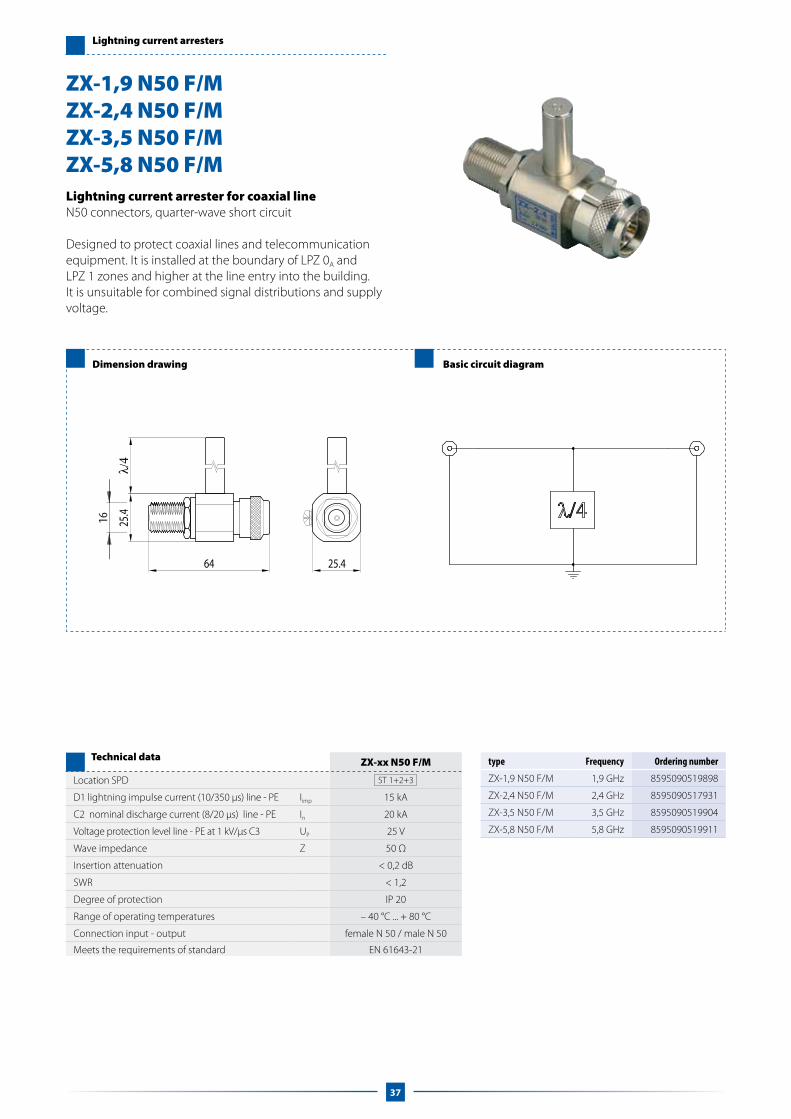
Lightning current arrester for coaxial lineN50 connectors, quarter-wave short circuit
Designed to protect coaxial lines and telecommunication equipment. It is installed at the boundary of LPZ 0A and LPZ 1 zones and higher at the line entry into the building. It is unsuitable for combined signal distributions and supply voltage.
ZX-xx N50 F/M
Location SPD ST 1+2+3
D1 lightning impulse current (10/350 μs) line - PE Iimp 15 kA
C2 nominal discharge current (8/20 μs) line - PE In 20 kA
Voltage protection level line - PE at 1 kV/μs C3 UP 25 V
Wave impedance Z 50 Ω
Insertion attenuation < 0,2 dB
SWR < 1,2
Degree of protection IP 20
Range of operating temperatures – 40 °C ... + 80 °C
Connection input - output female N 50 / male N 50
Meets the requirements of standard EN 61643-21
Technical data
ZX-1,9 N50 F/MZX-2,4 N50 F/MZX-3,5 N50 F/MZX-5,8 N50 F/M
type Frequency Ordering number
ZX-1,9 N50 F/M 1,9 GHz 8595090519898
ZX-2,4 N50 F/M 2,4 GHz 8595090517931
ZX-3,5 N50 F/M 3,5 GHz 8595090519904
ZX-5,8 N50 F/M 5,8 GHz 8595090519911
37
16

FX-090 B75 T F/F FX-230 B75 T F/F FX-090 F75 T F/F FX-230 F75 T F/F
Location SPD ST 1 ST 1 ST 1 ST 1
Maximum operating voltage Uc 70 V DC 180 V DC 70 V DC 180 V DC
Nominal current IL 4 A 4 A 4 A 4 A
D1 lightning impulse current (10/350 μs) line – SH Iimp 2,5 kA 2,5 kA 2,5 kA 2,5 kA
D1 lightning impulse current (10/350 μs) SH – PE Iimp 2,5 kA 2,5 kA 2,5 kA 2,5 kA
C2 nominal discharge current (8/20 μs) line - SH In 10 kA 10 kA 10 kA 10 kA
C2 nominal discharge current (8/20 μs) SH - PE In 10 kA 10 kA 10 kA 10 kA
C3 voltage protection level line – SH at 1 kV/μs Up 600 V 660 V 600 V 660 V
C3 voltage protection level SH – PE at 1 kV/μs Up 600 V 660 V 600 V 660 V
Wave impedance Z 75 Ω 75 Ω 75 Ω 75 Ω
Insertion attenuation < 0,6 dB < 0,6 dB < 0,2 dB < 0,2 dB
SWR < 1,2 < 1,2 < 1,3 < 1,3
Bandwidth f 0 – 2,15 GHz 0 – 2,15 GHz 0 – 2,15 GHz 0 – 2,15 GHz
Response time line – SH ta 100 ns 100 ns 100 ns 100 ns
Response time SH – PE ta 100 ns 100 ns 100 ns 100 ns
Degree of protection IP 20 IP 20 IP 20 IP 20
Range of operating temperatures – 40 °C … + 80 °C – 40 °C … + 80 °C – 40 °C … + 80 °C – 40 °C … + 80 °C
Connection input - output BNC 75 BNC 75 F 75 F 75
Meets the requirements of standard EN 61643-21 EN 61643-21 EN 61643-21 EN 61643-21
Ordering number 8595090533856 8595090533900 8595090533870 8595090533924
Technical data
Lightning current arresters
Dimension drawing Basic circuit diagram
Lightning current arrester for coaxial line BNC or F connectors
Designed to protect coaxial lines. It is installed at the boundary of LPZ 0A and LPZ 1 zones at the line entry into the building. It is suitable as the 1st level of surge protection in coordination with the SX type.
Installation by adapters for DIN rail or for screw mounting.
FX-090 B75 TFX-230 B75 T FX-090 F75 TFX-230 F75 T
conector BNC
38

SX-090 B75 SX-090 F75
Location SPD ST 3 ST 3
Maximum operating voltage Uc 29,1 V DC 29,1 V DC
Nominal current IL 4 A 4 A
C2 nominal discharge current (8/20 μs) line – PE In 1,5 kA 1,5 kA
C3 voltage protection level line – PE at 1 kV/μs Up 80 V 80 V
Wave impedance Z 75 Ω 75 Ω
Insertion attenuation < 1 dB < 1 dB
SWR < 1,7 < 1,7
Bandwidth f 1 MHz – 2,15 GHz 1 MHz – 2,15 GHz
Response time line – PE ta 1 ns 1 ns
Degree of protection IP 20 IP 20
Range of operating temperatures – 40 °C … + 80 °C – 40 °C … + 80 °C
Connection input – output BNC 75 F 75
Meets the requirements of standard EN 61643-21 EN 61643-21
Ordering number 8595090533955 8595090533979
Technical data
Surge Arresters
Dimension drawing Basic circuit diagram
Surge arrester for coaxial lineBNC and F connectors
Fine surge protection designed to protect coaxial inputs of TV systems. It is suitable as the 2nd level of surge protection in coordination with the FX type. It is installed at the boundary of LPZ 2 and LPZ 3 zones, directly before the equipment.
Installation by adapters for DIN rail or for screw moun-ting.
SX-090 B75SX-090 F75
conector BNC
conector F
39

Notes

PRODUCT RANGE
For more details please contact us or visit www.saltek.eu
Low voltageSPD type 1, type 2 and type 3 for lightning and surge protectionof LV distribution systems
Renewable energySPD for photovoltaic applications (AC side, DC side, communication lines),electric vehicle charging stations, wind turbines and biogas plants
Surger protection with RFI filterSPD type 3 to protect against surges and high frequency interferencevoltages caused by inverters
Control linesSurge protection devices for AI, AO, DI, DO and bus forcontrol, security or fire protection systems
Telecom linesSurge protection devices for analog, ISDN and ADSL lines and other DSLlines for installation on DIN rail or LSA-PLUS
Video/securitySurge protection devices for coaxial lines for N/F/BNC connectors for useon frequencies 0-5,8 GHz.
EthernetSurge protection devices for Ethernet category 5 and 6 and for Power overEthernet (POE, POE PLUS)

www.saltek.eu EN 2014/01
Manufactureand headquarter
SALTEK s.r.o.Drážďanská 85400 07 Ústí nad LabemCzech Republic
tel.: +420 475 655 511fax: +420 475 622 213GSM: +420 602 413 437e-mail: [email protected]
Sales officeand technical support
SALTEK TRADE, s.r.o.Vodňanská 1419/229198 00 Praha 9Czech Republic
tel.: +420 272 942 470fax: +420 267 913 411GSM: +420 602 472 633 e-mail: [email protected]