Embed Size (px)
Citation preview
CATALOGUEPRODUITS
>> FR
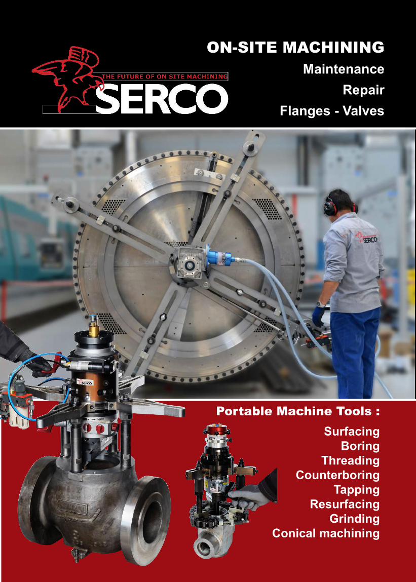
Portable Machine Tools :Surfacing
BoringThreading
CounterboringTapping
ResurfacingGrinding
Conical machining
ON-SITE MACHININGMaintenance
RepairFlanges - Valves
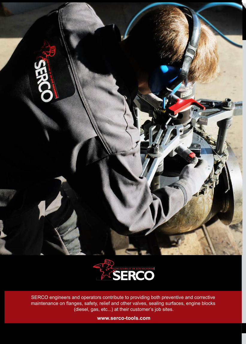
SERCO engineers and operators contribute to providing both preventive and corrective maintenance on flanges, safety, relief and other valves, sealing surfaces, engine blocks
(diesel, gas, etc...) at their customer’s job sites.
www.serco-tools.com
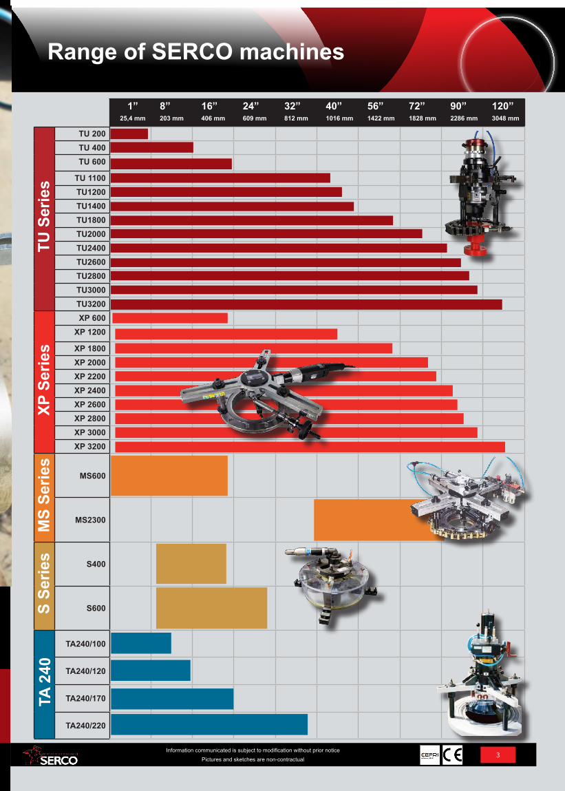
1”25,4 mm
8” 203 mm
16” 406 mm
24” 609 mm
32” 812 mm
40” 1016 mm
56” 1422 mm
72” 1828 mm
90” 2286 mm
120” 3048 mm
TU S
erie
s
TU 200TU 400TU 600
TU 1100TU1200TU1400TU1800TU2000TU2400TU2600TU2800TU3000TU3200
XP S
erie
s
XP 600XP 1200
XP 1800XP 2000XP 2200XP 2400XP 2600XP 2800XP 3000XP 3200
MS
Serie
s
MS600
MS2300
S Se
ries S400
S600
TA 2
40
TA240/100
TA240/120
TA240/170
TA240/220
3Information communicated is subject to modification without prior notice
Pictures and sketches are non-contractual
SERCO engineers and operators contribute to providing both preventive and corrective maintenance on flanges, safety, relief and other valves, sealing surfaces, engine blocks
(diesel, gas, etc...) at their customer’s job sites.
Range of SERCO machines
4Information communicated is subject to modification without prior notice
Pictures and sketches are non-contractual
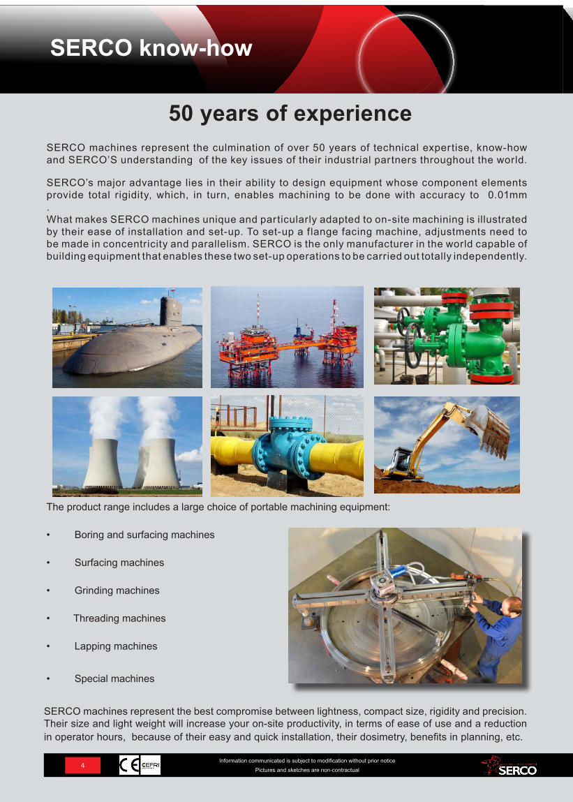
50 years of experienceSERCO machines represent the culmination of over 50 years of technical expertise, know-how and SERCO’S understanding of the key issues of their industrial partners throughout the world.
SERCO’s major advantage lies in their ability to design equipment whose component elements provide total rigidity, which, in turn, enables machining to be done with accuracy to 0.01mm. What makes SERCO machines unique and particularly adapted to on-site machining is illustrated by their ease of installation and set-up. To set-up a f lange facing machine, adjustments need to be made in concentricity and parallelism. SERCO is the only manufacturer in the world capable of building equipment that enables these two set-up operations to be carried out totally independently.
The product range includes a large choice of portable machining equipment:
• Boring and surfacing machines
• Surfacing machines
• Grinding machines
• Threading machines
• Lapping machines
• Special machines
SERCO machines represent the best compromise between lightness, compact size, rigidity and precision. Their size and light weight will increase your on-site productivity, in terms of ease of use and a reduction in operator hours, because of their easy and quick installation, their dosimetry, benefits in planning, etc.
SERCO know-how
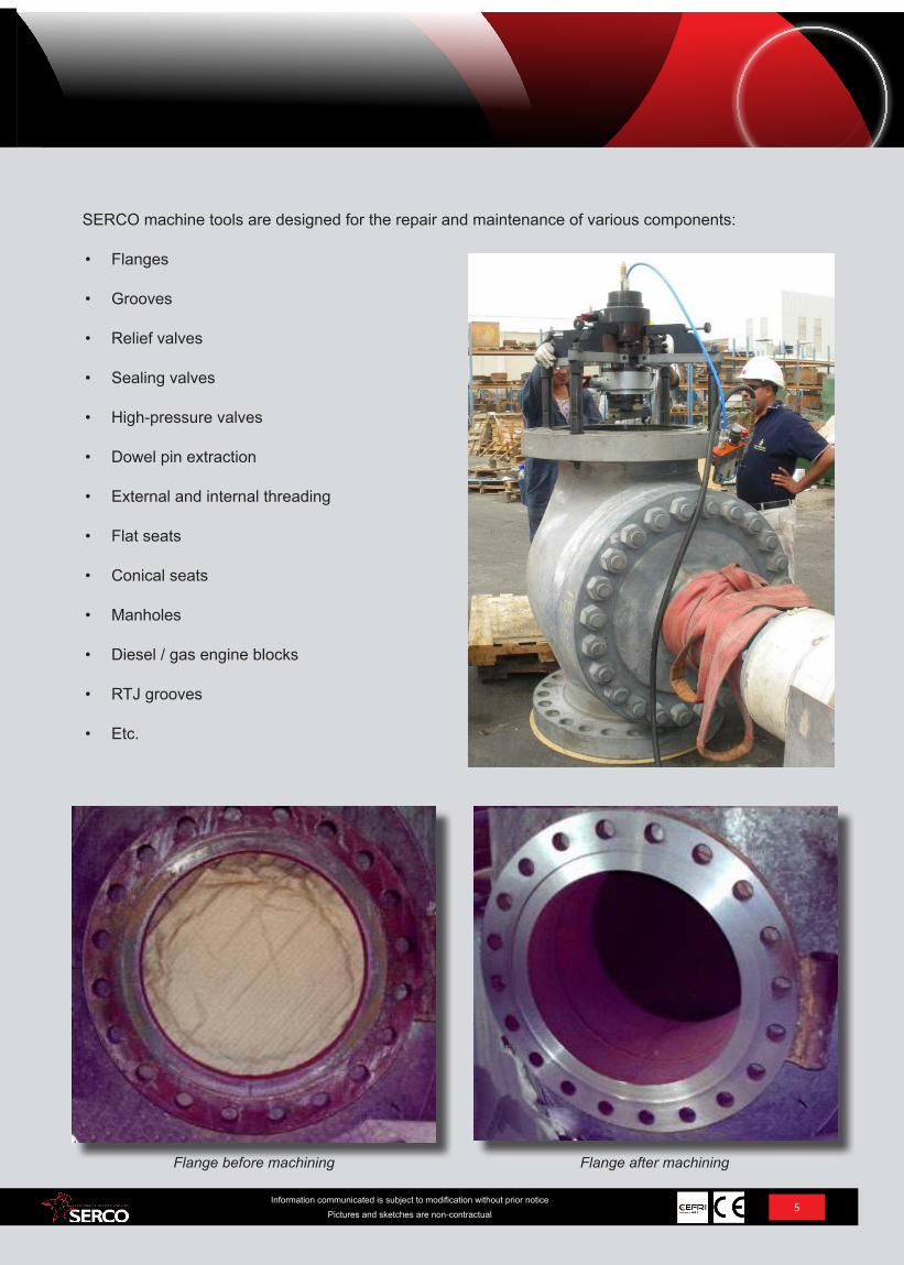
Flange before machining Flange after machining
5Information communicated is subject to modification without prior notice
Pictures and sketches are non-contractual
SERCO machine tools are designed for the repair and maintenance of various components:
• Flanges
• Grooves
• Relief valves
• Sealing valves
• High-pressure valves
• Dowel pin extraction
• External and internal threading
• Flat seats
• Conical seats
• Manholes
• Diesel / gas engine blocks
• RTJ grooves
• Etc.
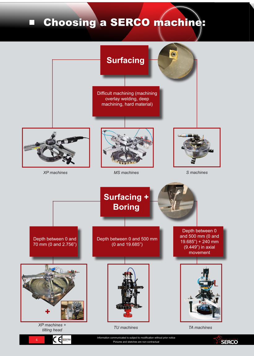
Surfacing
+
MS machinesXP machines S machines
XP machines + tilting head TU machines TA machines
Difficult machining (machining overlay welding, deep
machining, hard material)
Depth between 0 and 500 mm (0 and 19.685”) + 240 mm
(9.449”) in axial movement
Depth between 0 and 70 mm (0 and 2.756”)
Surfacing + Boring
Depth between 0 and 500 mm (0 and 19.685”)
6Information communicated is subject to modification without prior notice
Pictures and sketches are non-contractual
Choosing a SERCO machine:
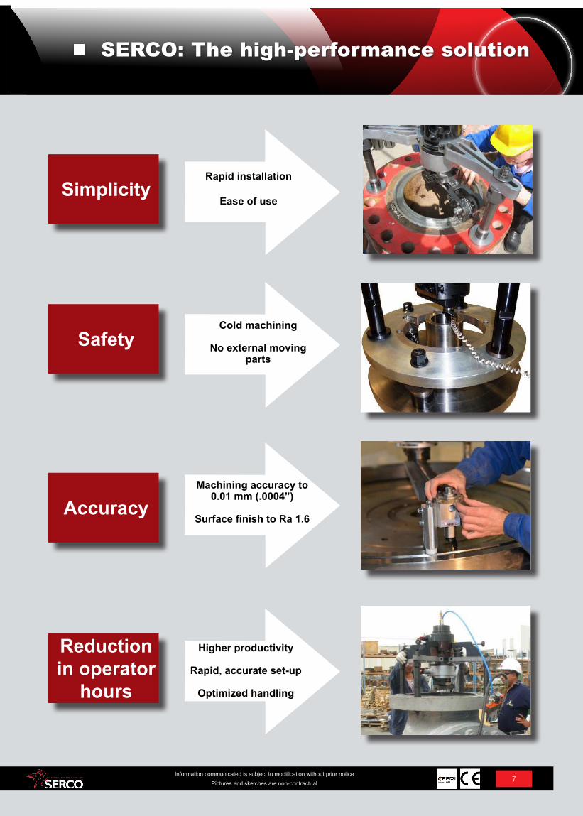
Simplicity
SERCO: The high-performance solution
Safety
Accuracy
Reduction in operator
hours
Rapid installation
Ease of use
Cold machining
No external moving parts
Machining accuracy to 0.01 mm (.0004”)
Surface finish to Ra 1.6
Higher productivity
Rapid, accurate set-up
Optimized handling
7Information communicated is subject to modification without prior notice
Pictures and sketches are non-contractual
Contents
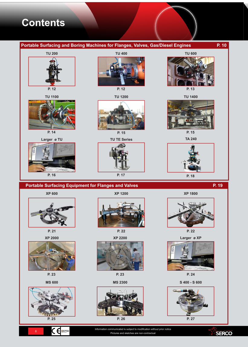
Portable Surfacing and Boring Machines for Flanges, Valves, Gas/Diesel Engines P. 10
TU 200 TU 400 TU 600
P. 12
TU 1100
P. 12 P. 13
P. 14 P. 15 P. 15
P. 16 P. 17
Portable Surfacing Equipment for Flanges and Valves P. 19
TU 1200 TU 1400
Larger ø TU TU TE Series
XP 600 XP 1200 XP 1800
P. 21
XP 2000
P. 22 P. 22
P. 23 P. 23 P. 24
XP 2200 Larger ø XP
MS 600 MS 2300 S 400 - S 600
P. 25 P. 26 P. 27
TA 240
P. 18
8Information communicated is subject to modification without prior notice
Pictures and sketches are non-contractual
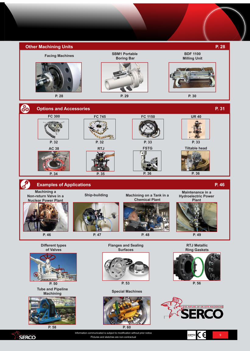
Different types of Valves
Flanges and Sealing Surfaces
RTJ Metallic Ring Gaskets
P. 50 P. 53 P. 56Tube and Pipeline
Machining Special Machines
P. 58 P. 60
Facing Machines SBM1 Portable Boring Bar
BDF 1100 Milling Unit
P. 28 P. 29 P. 30
Options and Accessories P. 31FC 300 FC 745 FC 1150
P. 32
UR 40
P. 32 P. 33 P. 33AC 38 RTJ
P. 34 P. 35
Examples of Applications P. 46Machining a
Non-return Valve in a Nuclear Power Plant
Ship-building Machining on a Tank in a Chemical Plant
P. 46
Maintenance in a Hydroelectric Power
Plant
P. 47 P. 48 P. 49
Other Machining Units P. 28
FSTG
P. 36
Tiltable head
P. 36
9Information communicated is subject to modification without prior notice
Pictures and sketches are non-contractual
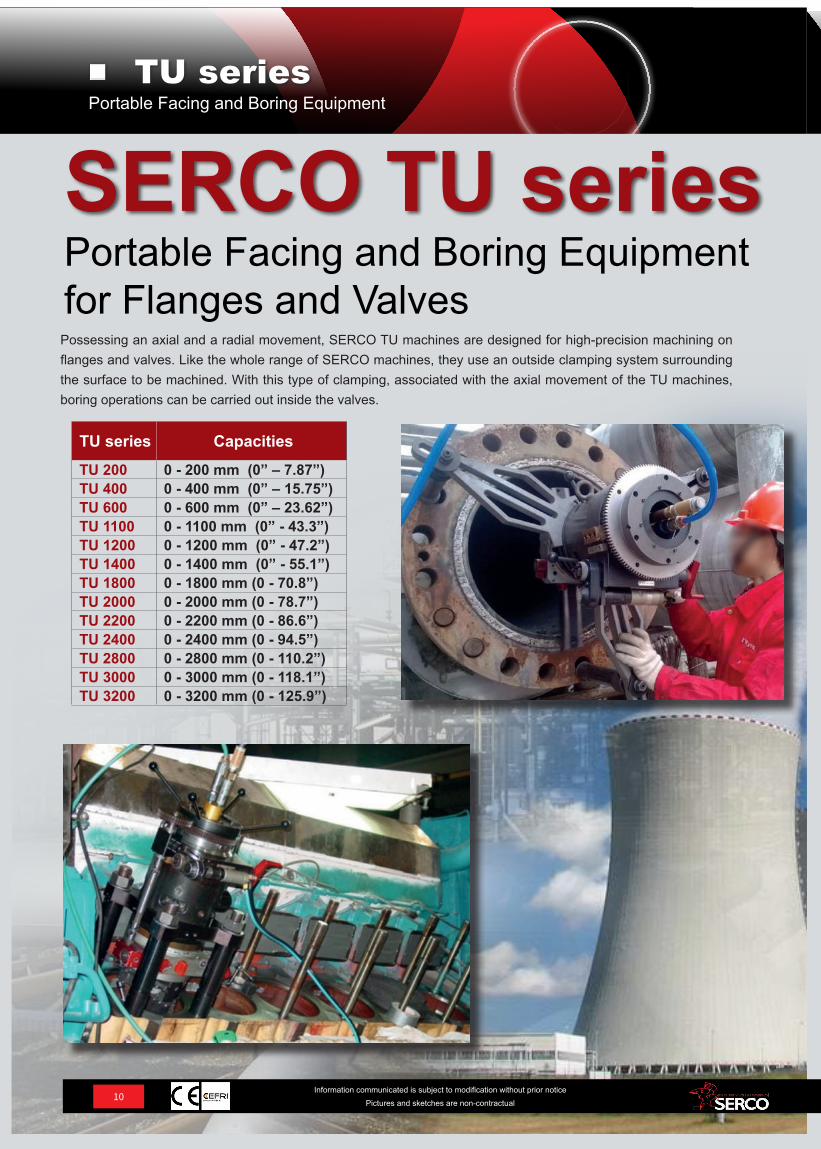
TU series CapacitiesTU 200 0 - 200 mm (0” – 7.87”)TU 400 0 - 400 mm (0” – 15.75”)TU 600 0 - 600 mm (0” – 23.62”)TU 1100 0 - 1100 mm (0” - 43.3”)TU 1200 0 - 1200 mm (0” - 47.2”)TU 1400 0 - 1400 mm (0” - 55.1”)TU 1800 0 - 1800 mm (0 - 70.8”)TU 2000 0 - 2000 mm (0 - 78.7”)TU 2200 0 - 2200 mm (0 - 86.6”)TU 2400 0 - 2400 mm (0 - 94.5”)TU 2800 0 - 2800 mm (0 - 110.2”)TU 3000 0 - 3000 mm (0 - 118.1”)TU 3200 0 - 3200 mm (0 - 125.9”)
Possessing an axial and a radial movement, SERCO TU machines are designed for high-precision machining on flanges and valves. Like the whole range of SERCO machines, they use an outside clamping system surrounding the surface to be machined. With this type of clamping, associated with the axial movement of the TU machines, boring operations can be carried out inside the valves.
10Information communicated is subject to modification without prior notice
Pictures and sketches are non-contractual
Portable Facing and Boring Equipment for Flanges and Valves
SERCO TU seriesPortable Facing and Boring Equipment
TU series
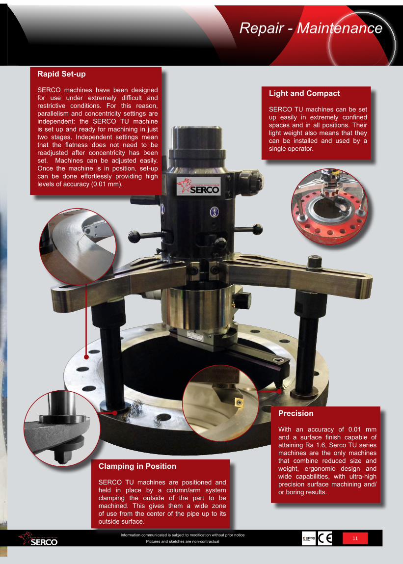
Rapid Set-up
SERCO machines have been designed for use under extremely difficult and restrictive conditions. For this reason, parallelism and concentricity settings are independent: the SERCO TU machine is set up and ready for machining in just two stages. Independent settings mean that the flatness does not need to be readjusted after concentricity has been set. Machines can be adjusted easily. Once the machine is in position, set-up can be done effortlessly providing high levels of accuracy (0.01 mm).
11Information communicated is subject to modification without prior notice
Pictures and sketches are non-contractual
Precision
With an accuracy of 0.01 mm and a surface finish capable of attaining Ra 1.6, Serco TU series machines are the only machines that combine reduced size and weight, ergonomic design and wide capabilities, with ultra-high precision surface machining and/or boring results.
Repair - Maintenance
Light and Compact
SERCO TU machines can be set up easily in extremely confined spaces and in all positions. Their light weight also means that they can be installed and used by a single operator.
Clamping in Position
SERCO TU machines are positioned and held in place by a column/arm system clamping the outside of the part to be machined. This gives them a wide zone of use from the center of the pipe up to its outside surface.
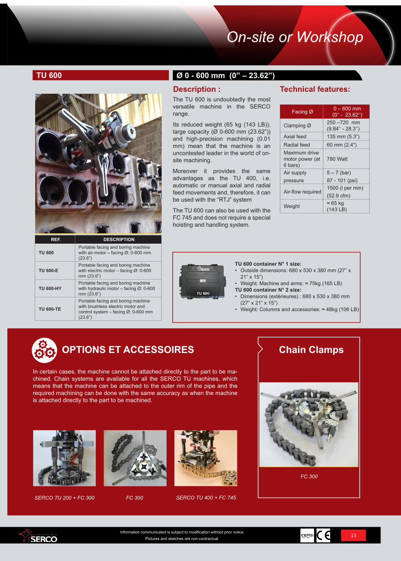
TU 400 container size:• Outside dimensions: 680 x 530 x 380 mm (27” x
21” x 15”) • Weight: machine and accessories: ≈ 65kg (143 LB)
REF. DESCRIPTION
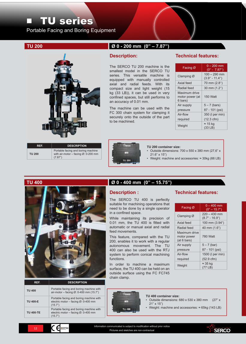
TU 200Portable facing and boring machine with air-motor – facing Ø: 0-200 mm (7.87”)
Facing Ø 0 – 400 mm (0” – 15.7“)
Clamping Ø 220 – 430 mm(8.7“ - 16.9“)
Axial feed 100 mm (3.94“)Radial feed 40 mm (1.6“)Maximum drive motor power (at 6 bars)
780 Watt
Air supply pressure
5 – 7 (bar)87 - 101 (psi)
Air-flow required
1500 (l per min)(52.9 cfm)
Weight ≈ 35 kg (77 LB)
Facing Ø 0 – 200 mm (0‘‘ - 7.87‘‘)
Clamping Ø 100 – 290 mm(3.9‘‘ - 11.4‘‘)
Axial feed 70 mm (2.8‘‘)Radial feed 30 mm (1.2‘‘)Maximum drive motor power (at 6 bars)
150 Watt
Air supply pressure
5 – 7 (bars)87 - 101 (psi)
Air-flow required
350 (l per min)(12.3 cfm)
Weight ≈ 15 kg (33 LB)
REF. DESCRIPTION
TU 400 Portable facing and boring machine with air-motor – facing Ø: 0-400 mm (15.7”)
TU 400-EPortable facing and boring machine with electric motor – facing Ø: 0-400 mm (15.7”)
TU 400-TEPortable facing and boring machine with electric motor – facing Ø: 0-400 mm (15.7”)
The SERCO TU 200 machine is the smallest model in the SERCO TU series. This versatile machine is equipped with manually controlled axial and radial feeds. With its compact size and light weight (15 kg (33 LB)), it can be used in very confined spaces, but still performs to an accuracy of 0.01 mm.
The machine can be used with the FC 300 chain system for clamping it securely onto the outside of the part to be machined.
The SERCO TU 400 is perfectly suitable for machining operations that need to be done by a single operator in a confined space.While maintaining its precision of 0.01 mm, the TU 400 is fitted with automatic or manual axial and radial feed movements.This feature, compared with the TU 200, enables it to work with a regular autonomous movement. The TU 400 can also be used with the RTJ system to perform conical machining functions. In order to machine a maximum surface, the TU 400 can be held on an outside surface using the FC FC745 chain clamp.
Technical features:
Technical features:Description:
Description :
Ø 0 - 200 mm (0” – 7.87”)
Ø 0 - 400 mm (0” – 15.75”)
TU 200
TU 400
TU 200 container size:• Outside dimensions: 700 x 550 x 380 mm (27,6” x
21.6” x 15”) • Weight: machine and accessories: ≈ 30kg (66 LB)
12Information communicated is subject to modification without prior notice
Pictures and sketches are non-contractual
Portable Facing and Boring EquipmentTU series
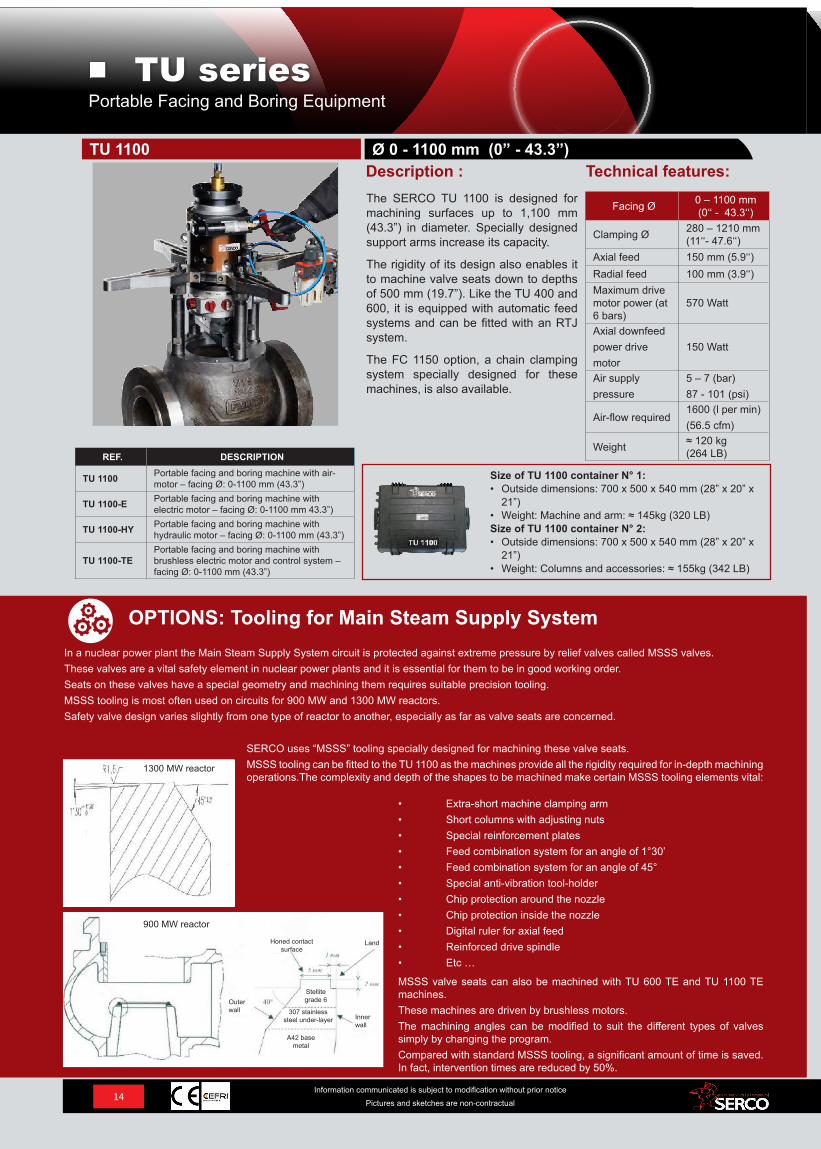
TU 600 container N° 1 size:• Outside dimensions: 680 x 530 x 380 mm (27” x
21” x 15”) • Weight: Machine and arms: ≈ 75kg (165 LB)TU 600 container N° 2 size:• Dimensions (extérieures) : 680 x 530 x 380 mm
(27” x 21” x 15”) • Weight: Columns and accessories: ≈ 48kg (106 LB)
REF. DESCRIPTION
TU 600Portable facing and boring machine with air-motor – facing Ø: 0-600 mm (23.6”)
TU 600-EPortable facing and boring machine with electric motor – facing Ø: 0-600 mm (23.6”)
TU 600-HYPortable facing and boring machine with hydraulic motor – facing Ø: 0-600 mm (23.6”)
TU 600-TE
Portable facing and boring machine with brushless electric motor and control system – facing Ø: 0-600 mm (23.6”)
Facing Ø 0 – 600 mm (0‘‘ - 23.62‘‘)
Clamping Ø 250 –720 mm(9.84‘‘ - 28.3‘‘)
Axial feed 135 mm (5.3“)Radial feed 60 mm (2.4“)Maximum drive motor power (at 6 bars)
780 Watt
Air supply pressure
5 – 7 (bar)87 - 101 (psi)
Air-flow required1500 (l per min)(52.9 cfm)
Weight ≈ 65 kg (143 LB)
The TU 600 is undoubtedly the most versatile machine in the SERCO range.
Its reduced weight (65 kg (143 LB)), large capacity (Ø 0-600 mm (23.62”)) and high-precision machining (0.01 mm) mean that the machine is an uncontested leader in the world of on-site machining.
Moreover it provides the same advantages as the TU 400, i.e. automatic or manual axial and radial feed movements and, therefore, it can be used with the “RTJ” system
The TU 600 can also be used with the FC 745 and does not require a special hoisting and handling system.
Technical features:Ø 0 - 600 mm (0” – 23.62”)
Description :TU 600
13Information communicated is subject to modification without prior notice
Pictures and sketches are non-contractual
SERCO TU 400 + FC 745FC 300SERCO TU 200 + FC 300
In certain cases, the machine cannot be attached directly to the part to be ma-chined. Chain systems are available for all the SERCO TU machines, which means that the machine can be attached to the outer rim of the pipe and the required machining can be done with the same accuracy as when the machine is attached directly to the part to be machined.
OPTIONS ET ACCESSOIRES
FC 300
Chain Clamps
On-site or Workshop
In a nuclear power plant the Main Steam Supply System circuit is protected against extreme pressure by relief valves called MSSS valves.These valves are a vital safety element in nuclear power plants and it is essential for them to be in good working order.Seats on these valves have a special geometry and machining them requires suitable precision tooling. MSSS tooling is most often used on circuits for 900 MW and 1300 MW reactors.Safety valve design varies slightly from one type of reactor to another, especially as far as valve seats are concerned.
OPTIONS: Tooling for Main Steam Supply System
SERCO uses “MSSS” tooling specially designed for machining these valve seats.MSSS tooling can be fitted to the TU 1100 as the machines provide all the rigidity required for in-depth machining operations.The complexity and depth of the shapes to be machined make certain MSSS tooling elements vital:
MSSS valve seats can also be machined with TU 600 TE and TU 1100 TE machines.These machines are driven by brushless motors.The machining angles can be modified to suit the different types of valves simply by changing the program. Compared with standard MSSS tooling, a significant amount of time is saved. In fact, intervention times are reduced by 50%.
• Extra-short machine clamping arm• Short columns with adjusting nuts • Special reinforcement plates• Feed combination system for an angle of 1°30’• Feed combination system for an angle of 45°• Special anti-vibration tool-holder• Chip protection around the nozzle • Chip protection inside the nozzle • Digital ruler for axial feed • Reinforced drive spindle• Etc …
Honed contact surface
Land
Inner wall
Outer wall
A42 base metal
307 stainless steel under-layer
Stellite grade 6
REF. DESCRIPTION
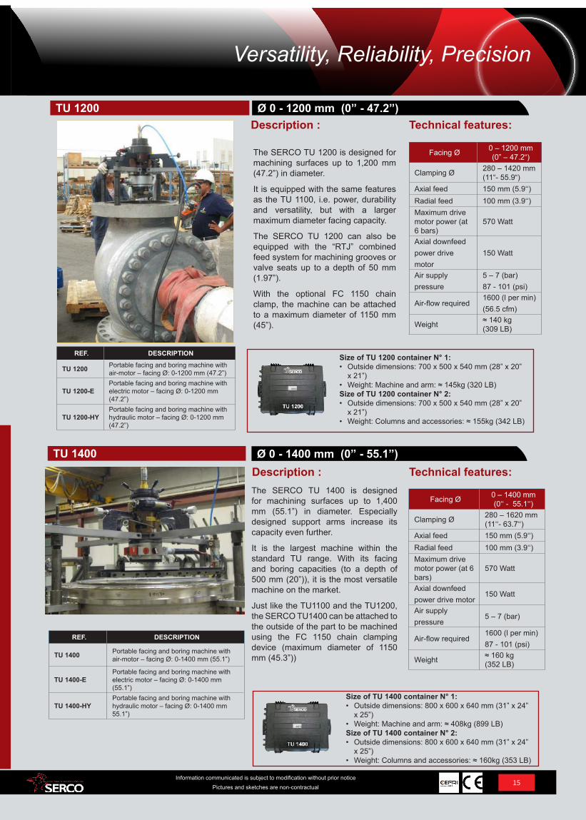
TU 1100 Portable facing and boring machine with air-motor – facing Ø: 0-1100 mm (43.3”)
TU 1100-E Portable facing and boring machine with electric motor – facing Ø: 0-1100 mm 43.3”)
TU 1100-HY Portable facing and boring machine with hydraulic motor – facing Ø: 0-1100 mm (43.3”)
TU 1100-TEPortable facing and boring machine with brushless electric motor and control system – facing Ø: 0-1100 mm (43.3”)
Facing Ø 0 – 1100 mm (0‘‘ - 43.3‘‘)
Clamping Ø 280 – 1210 mm(11‘‘- 47.6‘‘)
Axial feed 150 mm (5.9‘‘)Radial feed 100 mm (3.9‘‘)Maximum drive motor power (at 6 bars)
570 Watt
Axial downfeed power drive motor
150 Watt
Air supply pressure
5 – 7 (bar)87 - 101 (psi)
Air-flow required1600 (l per min)(56.5 cfm)
Weight ≈ 120 kg (264 LB)
The SERCO TU 1100 is designed for machining surfaces up to 1,100 mm (43.3”) in diameter. Specially designed support arms increase its capacity.
The rigidity of its design also enables it to machine valve seats down to depths of 500 mm (19.7”). Like the TU 400 and 600, it is equipped with automatic feed systems and can be fitted with an RTJ system.
The FC 1150 option, a chain clamping system specially designed for these machines, is also available.
Technical features:Description :Ø 0 - 1100 mm (0” - 43.3”)TU 1100
Size of TU 1100 container N° 1:• Outside dimensions: 700 x 500 x 540 mm (28” x 20” x
21”) • Weight: Machine and arm: ≈ 145kg (320 LB)Size of TU 1100 container N° 2:• Outside dimensions: 700 x 500 x 540 mm (28” x 20” x
21”) • Weight: Columns and accessories: ≈ 155kg (342 LB)
14Information communicated is subject to modification without prior notice
Pictures and sketches are non-contractual
Portable Facing and Boring EquipmentTU series
1300 MW reactor
900 MW reactor
Size of TU 1200 container N° 1:• Outside dimensions: 700 x 500 x 540 mm (28” x 20”
x 21”) • Weight: Machine and arm: ≈ 145kg (320 LB)Size of TU 1200 container N° 2:• Outside dimensions: 700 x 500 x 540 mm (28” x 20”
x 21”) • Weight: Columns and accessories: ≈ 155kg (342 LB)
Size of TU 1400 container N° 1:• Outside dimensions: 800 x 600 x 640 mm (31” x 24”
x 25”) • Weight: Machine and arm: ≈ 408kg (899 LB)Size of TU 1400 container N° 2:• Outside dimensions: 800 x 600 x 640 mm (31” x 24”
x 25”) • Weight: Columns and accessories: ≈ 160kg (353 LB)
REF. DESCRIPTION
TU 1400 Portable facing and boring machine with air-motor – facing Ø: 0-1400 mm (55.1”)
TU 1400-EPortable facing and boring machine with electric motor – facing Ø: 0-1400 mm (55.1”)
TU 1400-HYPortable facing and boring machine with hydraulic motor – facing Ø: 0-1400 mm 55.1”)
Facing Ø 0 – 1200 mm (0” – 47.2“)
Clamping Ø 280 – 1420 mm(11“- 55.9“)
Axial feed 150 mm (5.9‘‘)Radial feed 100 mm (3.9‘‘)Maximum drive motor power (at 6 bars)
570 Watt
Axial downfeed power drive motor
150 Watt
Air supply pressure
5 – 7 (bar)87 - 101 (psi)
Air-flow required1600 (l per min)(56.5 cfm)
Weight ≈ 140 kg (309 LB)
REF. DESCRIPTION
TU 1200 Portable facing and boring machine with air-motor – facing Ø: 0-1200 mm (47.2”)
TU 1200-EPortable facing and boring machine with electric motor – facing Ø: 0-1200 mm (47.2”)
TU 1200-HYPortable facing and boring machine with hydraulic motor – facing Ø: 0-1200 mm (47.2”)
The SERCO TU 1200 is designed for machining surfaces up to 1,200 mm (47.2”) in diameter.
It is equipped with the same features as the TU 1100, i.e. power, durability and versatility, but with a larger maximum diameter facing capacity.
The SERCO TU 1200 can also be equipped with the “RTJ” combined feed system for machining grooves or valve seats up to a depth of 50 mm (1.97”).
With the optional FC 1150 chain clamp, the machine can be attached to a maximum diameter of 1150 mm (45”).
Technical features:Description :
Facing Ø 0 – 1400 mm (0‘‘ - 55.1‘‘)
Clamping Ø 280 – 1620 mm(11‘‘- 63.7‘‘)
Axial feed 150 mm (5.9‘‘)Radial feed 100 mm (3.9‘‘)Maximum drive motor power (at 6 bars)
570 Watt
Axial downfeed power drive motor
150 Watt
Air supply pressure
5 – 7 (bar)
Air-flow required1600 (l per min)87 - 101 (psi)
Weight ≈ 160 kg(352 LB)
The SERCO TU 1400 is designed for machining surfaces up to 1,400 mm (55.1”) in diameter. Especially designed support arms increase its capacity even further.
It is the largest machine within the standard TU range. With its facing and boring capacities (to a depth of 500 mm (20”)), it is the most versatile machine on the market.
Just like the TU1100 and the TU1200, the SERCO TU1400 can be attached to the outside of the part to be machined using the FC 1150 chain clamping device (maximum diameter of 1150 mm (45.3”))
Technical features:Ø 0 - 1400 mm (0” - 55.1”)
Description :
Ø 0 - 1200 mm (0” - 47.2”)
TU 1400
TU 1200
15Information communicated is subject to modification without prior notice
Pictures and sketches are non-contractual
Versatility, Reliability, Precision
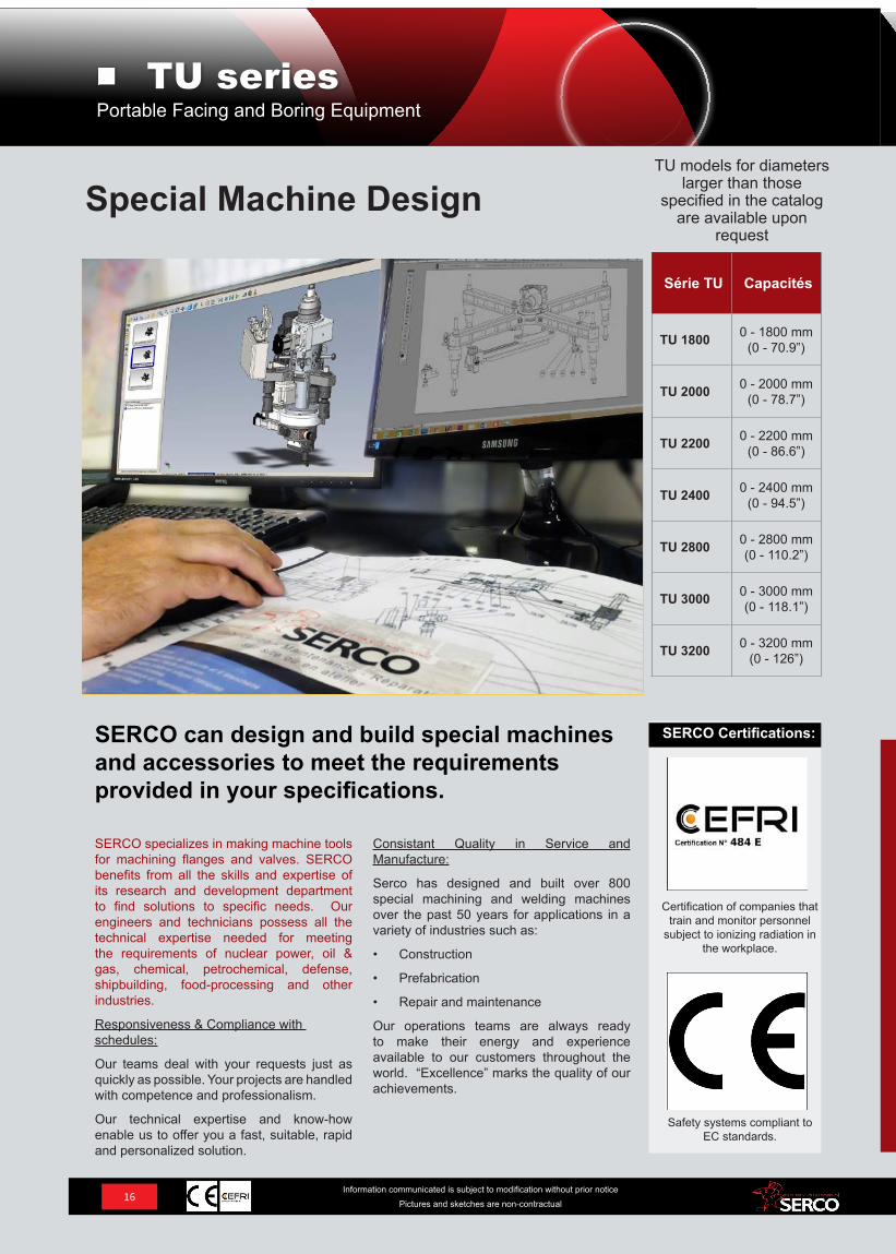
TU models for diameters larger than those
specified in the catalog are available upon
request
Série TU Capacités
TU 1800 0 - 1800 mm(0 - 70.9”)
TU 2000 0 - 2000 mm(0 - 78.7”)
TU 2200 0 - 2200 mm(0 - 86.6”)
TU 2400 0 - 2400 mm(0 - 94.5”)
TU 2800 0 - 2800 mm(0 - 110.2”)
TU 3000 0 - 3000 mm(0 - 118.1”)
TU 3200 0 - 3200 mm(0 - 126”)
SERCO specializes in making machine tools for machining flanges and valves. SERCO benefits from all the skills and expertise of its research and development department to find solutions to specific needs. Our engineers and technicians possess all the technical expertise needed for meeting the requirements of nuclear power, oil & gas, chemical, petrochemical, defense, shipbuilding, food-processing and other industries.
Responsiveness & Compliance with schedules:
Our teams deal with your requests just as quickly as possible. Your projects are handled with competence and professionalism.
Our technical expertise and know-how enable us to offer you a fast, suitable, rapid and personalized solution.
Consistant Quality in Service and Manufacture:
Serco has designed and built over 800 special machining and welding machines over the past 50 years for applications in a variety of industries such as:
• Construction
• Prefabrication
• Repair and maintenance
Our operations teams are always ready to make their energy and experience available to our customers throughout the world. “Excellence” marks the quality of our achievements.
SERCO can design and build special machines and accessories to meet the requirements provided in your specifications.
Special Machine Design
Safety systems compliant to EC standards.
Certification of companies that train and monitor personnel
subject to ionizing radiation in the workplace.
SERCO Certifications:
16Information communicated is subject to modification without prior notice
Pictures and sketches are non-contractual
Portable Facing and Boring EquipmentTU series
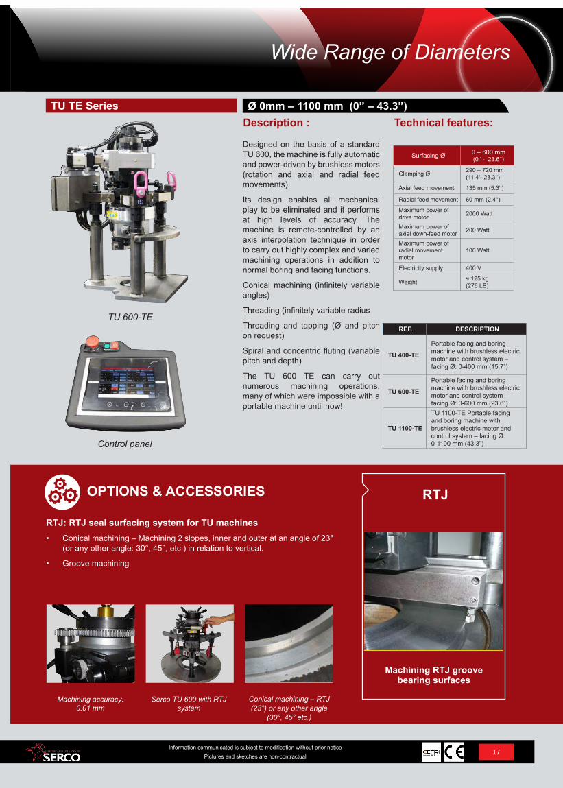
Control panel
TU 600-TEREF. DESCRIPTION
TU 400-TE
Portable facing and boring machine with brushless electric motor and control system – facing Ø: 0-400 mm (15.7”)
TU 600-TE
Portable facing and boring machine with brushless electric motor and control system – facing Ø: 0-600 mm (23.6”)
TU 1100-TE
TU 1100-TE Portable facing and boring machine with brushless electric motor and control system – facing Ø: 0-1100 mm (43.3”)
Surfacing Ø 0 – 600 mm (0‘‘ - 23.6‘‘)
Clamping Ø 290 – 720 mm(11.4‘- 28.3‘‘)
Axial feed movement 135 mm (5.3‘‘)
Radial feed movement 60 mm (2.4‘‘)
Maximum power of drive motor 2000 Watt
Maximum power of axial down-feed motor 200 Watt
Maximum power of radial movement motor
100 Watt
Electricity supply 400 V
Weight ≈ 125 kg(276 LB)
Designed on the basis of a standard TU 600, the machine is fully automatic and power-driven by brushless motors (rotation and axial and radial feed movements).
Its design enables all mechanical play to be eliminated and it performs at high levels of accuracy. The machine is remote-controlled by an axis interpolation technique in order to carry out highly complex and varied machining operations in addition to normal boring and facing functions.
Conical machining (infinitely variable angles)
Threading (infinitely variable radius
Threading and tapping (Ø and pitch on request)
Spiral and concentric fluting (variable pitch and depth)
The TU 600 TE can carry out numerous machining operations, many of which were impossible with a portable machine until now!
Technical features:Ø 0mm – 1100 mm (0” – 43.3”)
Description :TU TE Series
17Information communicated is subject to modification without prior notice
Pictures and sketches are non-contractual
Conical machining – RTJ (23°) or any other angle
(30°, 45° etc.)
Serco TU 600 with RTJ system
Machining accuracy: 0.01 mm
RTJ: RTJ seal surfacing system for TU machines• Conical machining – Machining 2 slopes, inner and outer at an angle of 23°
(or any other angle: 30°, 45°, etc.) in relation to vertical.
• Groove machining
OPTIONS & ACCESSORIES
Machining RTJ groove bearing surfaces
RTJ
Wide Range of Diameters
Machining liner bearing surfaces on SULZER engines.
Resurfacing six upper bores Ø 505 followed by positioning inserts.
Resurfacing six intermediate bores Ø 500 followed by positioning six inserts.
Tolerances to be met: 0.03 mm (.001”).
SERCO equipment: TA 240 / 220.
Machining 6 cylinders + positioning inserts in ten days.
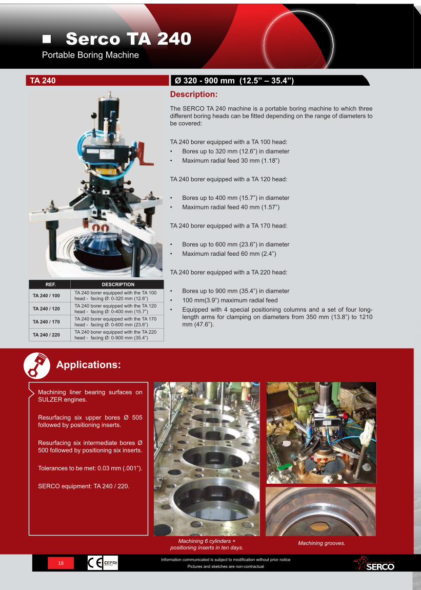
REF. DESCRIPTION
TA 240 / 100 TA 240 borer equipped with the TA 100 head - facing Ø: 0-320 mm (12.6”)
TA 240 / 120 TA 240 borer equipped with the TA 120 head - facing Ø: 0-400 mm (15.7”)
TA 240 / 170 TA 240 borer equipped with the TA 170 head - facing Ø: 0-600 mm (23.6”)
TA 240 / 220 TA 240 borer equipped with the TA 220 head - facing Ø: 0-900 mm (35.4”)
The SERCO TA 240 machine is a portable boring machine to which three different boring heads can be fitted depending on the range of diameters to be covered:
TA 240 borer equipped with a TA 100 head:• Bores up to 320 mm (12.6”) in diameter• Maximum radial feed 30 mm (1.18”)
TA 240 borer equipped with a TA 120 head:
• Bores up to 400 mm (15.7”) in diameter• Maximum radial feed 40 mm (1.57”)
TA 240 borer equipped with a TA 170 head:
• Bores up to 600 mm (23.6”) in diameter• Maximum radial feed 60 mm (2.4”)
TA 240 borer equipped with a TA 220 head:
• Bores up to 900 mm (35.4”) in diameter• 100 mm(3.9”) maximum radial feed• Equipped with 4 special positioning columns and a set of four long-
length arms for clamping on diameters from 350 mm (13.8”) to 1210 mm (47.6”).
Description:Ø 320 - 900 mm (12.5” – 35.4”)TA 240
Applications:
Machining grooves.
Portable Boring MachineSerco TA 240
18Information communicated is subject to modification without prior notice
Pictures and sketches are non-contractual
19Information communicated is subject to modification without prior notice
Pictures and sketches are non-contractual
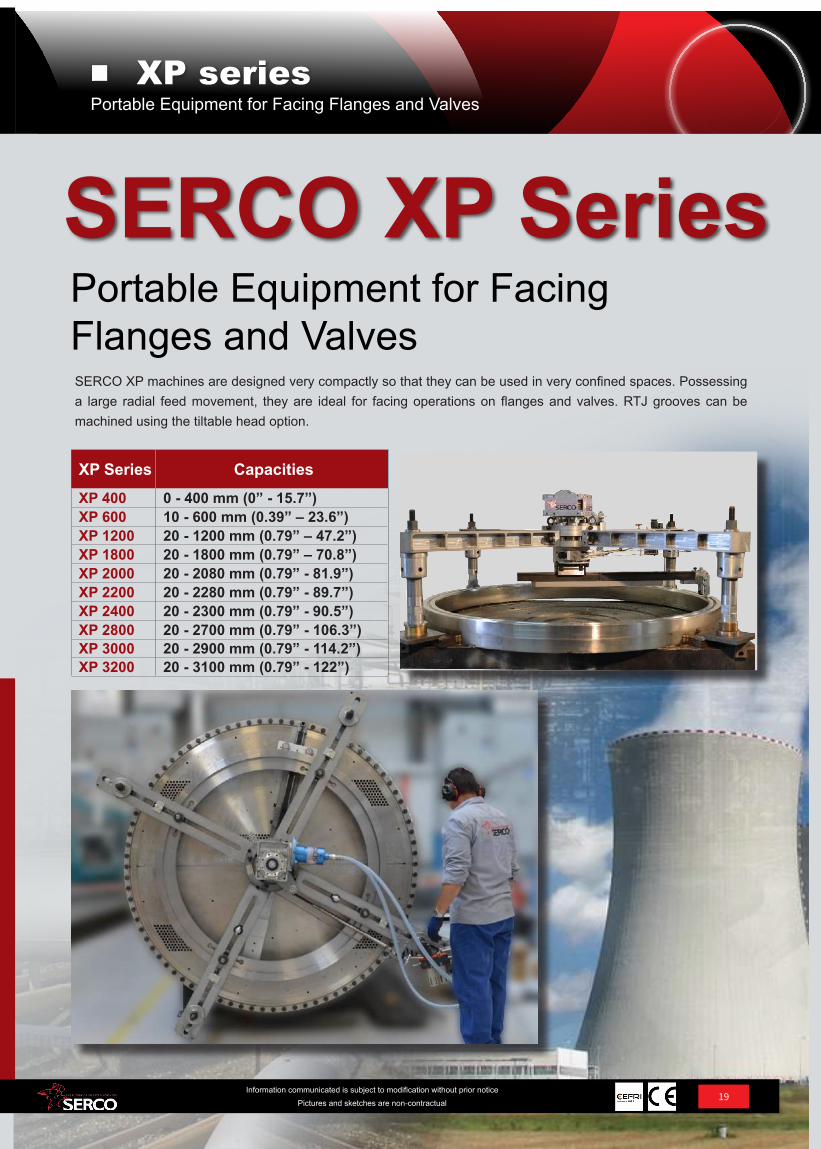
XP Series CapacitiesXP 400 0 - 400 mm (0” - 15.7”)XP 600 10 - 600 mm (0.39” – 23.6”)XP 1200 20 - 1200 mm (0.79” – 47.2”)XP 1800 20 - 1800 mm (0.79” – 70.8”)XP 2000 20 - 2080 mm (0.79” - 81.9”)XP 2200 20 - 2280 mm (0.79” - 89.7”)XP 2400 20 - 2300 mm (0.79” - 90.5”)XP 2800 20 - 2700 mm (0.79” - 106.3”)XP 3000 20 - 2900 mm (0.79” - 114.2”)XP 3200 20 - 3100 mm (0.79” - 122”)
SERCO XP machines are designed very compactly so that they can be used in very confined spaces. Possessing a large radial feed movement, they are ideal for facing operations on flanges and valves. RTJ grooves can be machined using the tiltable head option.
Portable Equipment for Facing Flanges and Valves
SERCO XP SeriesPortable Equipment for Facing Flanges and Valves
XP series
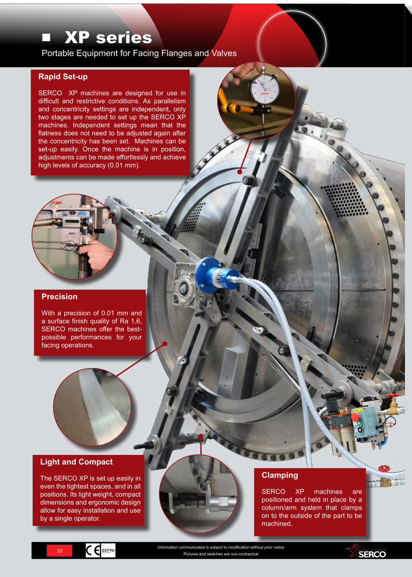
Rapid Set-up
SERCO XP machines are designed for use in difficult and restrictive conditions. As parallelism and concentricity settings are independent, only two stages are needed to set up the SERCO XP machines. Independent settings mean that the flatness does not need to be adjusted again after the concentricity has been set. Machines can be set-up easily. Once the machine is in position, adjustments can be made effortlessly and achieve high levels of accuracy (0.01 mm).
20Information communicated is subject to modification without prior notice
Pictures and sketches are non-contractual
Precision
With a precision of 0.01 mm and a surface finish quality of Ra 1.6, SERCO machines offer the best-possible performances for your facing operations.
Clamping
SERCO XP machines are positioned and held in place by a column/arm system that clamps on to the outside of the part to be machined.
Light and Compact
The SERCO XP is set up easily in even the tightest spaces, and in all positions. Its light weight, compact dimensions and ergonomic design allow for easy installation and use by a single operator.
Portable Equipment for Facing Flanges and ValvesXP series
REF. DESCRIPTION
XP 400 Portable flange facing machine with air-motor – facing Ø: 0-400 mm (0’’ - 15.7”)
XP 400-E Portable flange facing machine with electric motor – facing Ø: 0-400 mm (0’’ - 15.7”)
XP 400-HY Portable flange facing machine with hydraulic motor – facing Ø: 0-400 mm (0’’ - 15.7”)
Type XP 400
Radial movement 30 mm (1.2“)
Automatic radial feed (2 speeds) manuam
Minimum facing Ø 0 mm (0”)
Maximum facing Ø 400 mm (15.7“)
Minimum clamping Ø 110 mm (4.4“)
Maximum clamping Ø 500 mm (19.6”)
Maximum drive motor power at 6 bars 780 Watt
Drive motor speed under no-load conditions
100 RPM
Air supply pressure in bars
5 to 7 bar(72 to 101 psi)
Air-flow 1500 l per min (53 cfm)
Weight (approximate) -
Clamping system FSTG
Tiltable head (bores, RTJ grooves, conical machining)
Yes
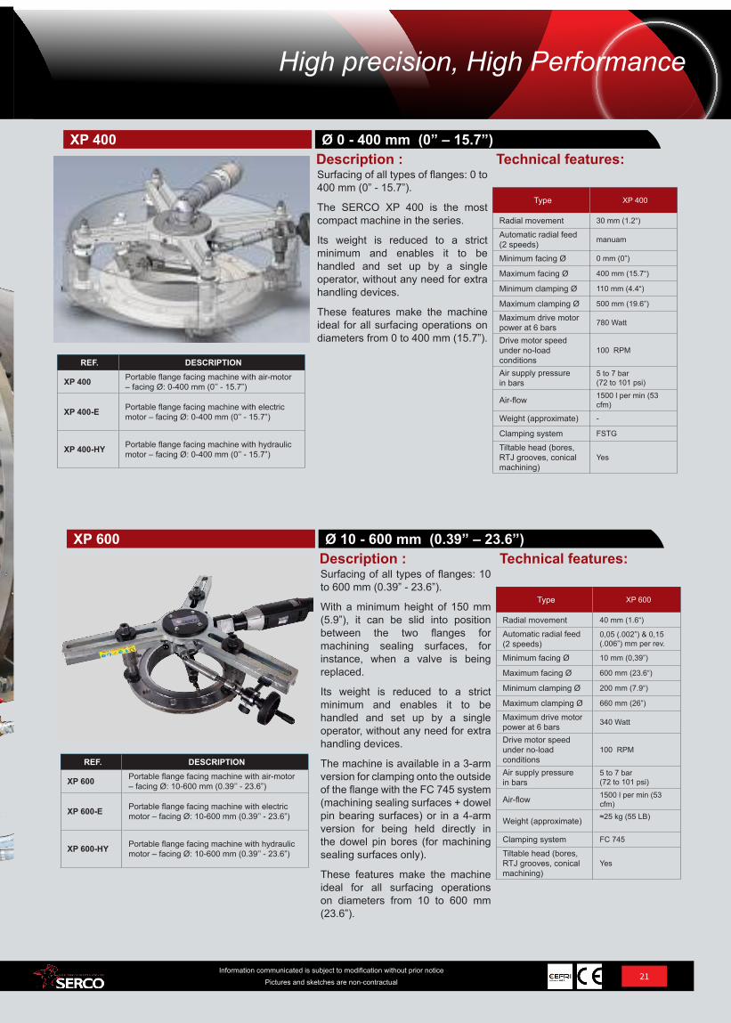
Surfacing of all types of flanges: 0 to 400 mm (0” - 15.7”).
The SERCO XP 400 is the most compact machine in the series.
Its weight is reduced to a strict minimum and enables it to be handled and set up by a single operator, without any need for extra handling devices.
These features make the machine ideal for all surfacing operations on diameters from 0 to 400 mm (15.7”).
Technical features:Description :Ø 0 - 400 mm (0” – 15.7”)XP 400
REF. DESCRIPTION
XP 600 Portable flange facing machine with air-motor – facing Ø: 10-600 mm (0.39’’ - 23.6”)
XP 600-E Portable flange facing machine with electric motor – facing Ø: 10-600 mm (0.39’’ - 23.6”)
XP 600-HY Portable flange facing machine with hydraulic motor – facing Ø: 10-600 mm (0.39’’ - 23.6”)
Type XP 600
Radial movement 40 mm (1.6“)
Automatic radial feed (2 speeds)
0,05 (.002”) & 0,15 (.006”) mm per rev.
Minimum facing Ø 10 mm (0,39”)
Maximum facing Ø 600 mm (23.6“)
Minimum clamping Ø 200 mm (7.9“)
Maximum clamping Ø 660 mm (26”)
Maximum drive motor power at 6 bars 340 Watt
Drive motor speed under no-load conditions
100 RPM
Air supply pressure in bars
5 to 7 bar(72 to 101 psi)
Air-flow 1500 l per min (53 cfm)
Weight (approximate) ≈25 kg (55 LB)
Clamping system FC 745
Tiltable head (bores, RTJ grooves, conical machining)
Yes
Surfacing of all types of flanges: 10 to 600 mm (0.39” - 23.6”).
With a minimum height of 150 mm (5.9”), it can be slid into position between the two flanges for machining sealing surfaces, for instance, when a valve is being replaced.
Its weight is reduced to a strict minimum and enables it to be handled and set up by a single operator, without any need for extra handling devices.
The machine is available in a 3-arm version for clamping onto the outside of the flange with the FC 745 system (machining sealing surfaces + dowel pin bearing surfaces) or in a 4-arm version for being held directly in the dowel pin bores (for machining sealing surfaces only).
These features make the machine ideal for all surfacing operations on diameters from 10 to 600 mm (23.6”).
Technical features:Description :Ø 10 - 600 mm (0.39” – 23.6”)XP 600
21Information communicated is subject to modification without prior notice
Pictures and sketches are non-contractual
High precision, High Performance
Type XP 1200
Radial movement 100 mm (4“)
Automatic radial feed (2 speeds)
0,062 (.002”) & 0,186 (.007”) mm per rev.
Minimum facing Ø 20 mm (0.79”)
Maximum facing Ø 1200 mm (47.2“)
Minimum clamping Ø 500 mm (20“)
Maximum clamping Ø 1400 mm (55”)
Maximum drive motor power at 6 bars 2000 Watt
Drive motor speed under no-load conditions
45 RPM
Air supply pressure in bars
5 to 7 bars (72 to 101 psi)
Air-flow 2500 l per min (88 cfm)
Weight (approximate) ≈ 220 kg (485 LB)
Clamping system FSTG 2050
Tiltable head (bores, RTJ grooves, conical machining)
Yes
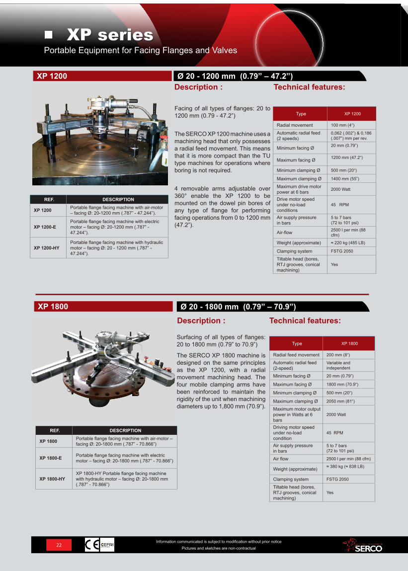
Facing of all types of flanges: 20 to 1200 mm (0.79 - 47.2”)
The SERCO XP 1200 machine uses a machining head that only possesses a radial feed movement. This means that it is more compact than the TU type machines for operations where boring is not required.
4 removable arms adjustable over 360° enable the XP 1200 to be mounted on the dowel pin bores of any type of flange for performing facing operations from 0 to 1200 mm (47.2”).
Technical features:Description :Ø 20 - 1200 mm (0.79” – 47.2”)XP 1200
REF. DESCRIPTION
XP 1200 Portable flange facing machine with air-motor – facing Ø: 20-1200 mm (.787” - 47.244”).
XP 1200-EPortable flange facing machine with electric motor – facing Ø: 20-1200 mm (.787” - 47.244”).
XP 1200-HYPortable flange facing machine with hydraulic motor – facing Ø: 20 - 1200 mm (.787” - 47.244”).
REF. DESCRIPTION
XP 1800 Portable flange facing machine with air-motor – facing Ø: 20-1800 mm (.787” - 70.866”)
XP 1800-E Portable flange facing machine with electric motor – facing Ø: 20-1800 mm (.787” - 70.866”)
XP 1800-HYXP 1800-HY Portable flange facing machine with hydraulic motor – facing Ø: 20-1800 mm (.787” - 70.866”)
Surfacing of all types of flanges: 20 to 1800 mm (0.79” to 70.9”)
The SERCO XP 1800 machine is designed on the same principles as the XP 1200, with a radial movement machining head. The four mobile clamping arms have been reinforced to maintain the rigidity of the unit when machining diameters up to 1,800 mm (70.9”).
Technical features:Ø 20 - 1800 mm (0.79” – 70.9”)
Description :
Type XP 1800
Radial feed movement 200 mm (8“)
Automatic radial feed (2-speed)
Variable and independent
Minimum facing Ø 20 mm (0.79”)
Maximum facing Ø 1800 mm (70.9“)
Minimum clamping Ø 500 mm (20“)
Maximum clamping Ø 2050 mm (81“)
Maximum motor output power in Watts at 6 bars
2000 Watt
Driving motor speed under no-load condition
45 RPM
Air supply pressure in bars
5 to 7 bars (72 to 101 psi)
Air flow 2500 l per min (88 cfm)
Weight (approximate) ≈ 380 kg (≈ 838 LB)
Clamping system FSTG 2050
Tiltable head (bores, RTJ grooves, conical machining)
Yes
XP 1800
22Information communicated is subject to modification without prior notice
Pictures and sketches are non-contractual
Portable Equipment for Facing Flanges and ValvesXP series
REF. DESCRIPTION
XP 2000 Portable flange facing machine with air-motor – facing Ø: 20-2080 mm
XP 2000-E Portable flange facing machine with electric motor – facing Ø: 20-2080 mm
XP 2000-HY Portable flange facing machine with hydraulic motor – facing Ø: 20-2080 mm
Type XP 2000
Radial feed movement 200 mm (8“)
Automatic radial feed (2-speed)
Variable and independent
Minimum facing Ø 20 mm (0.79”)
Maximum facing Ø 2080 mm (82“)
Minimum clamping Ø 650 mm (25.6“)
Maximum clamping Ø 2250 mm (88.6“)
Maximum motor output power in Watts at 6 bars
3000 Watt
Driving motor speed under no-load condition 45 RPM
Air supply pressure in bars
5 to 7 bars (72 to 101 psi)
Air flow 3500 l per min (124 cfm)
Weight (approximate) ≈450 kg (99 LB)
Clamping system FSTG 2500
Tiltable head (bores, RTJ grooves, conical machining)
Yes
REF. DESCRIPTION
XP 2200 Portable flange facing machine with air-motor – facing Ø: 20-2280 mm (.787” - 89.764”)
XP 2200-EPortable flange facing machine with electric motor – facing Ø: 20-2280 mm (.787” - 89.764”)
XP 2200-HYPortable flange facing machine with hydraulic motor – facing Ø: 20-2280 mm (.787” - 89.764”)
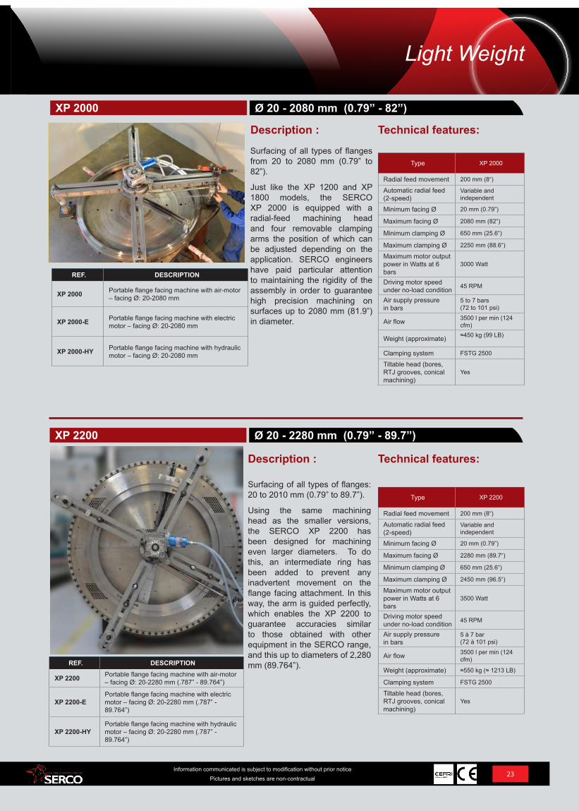
Surfacing of all types of flanges from 20 to 2080 mm (0.79” to 82”).
Just like the XP 1200 and XP 1800 models, the SERCO XP 2000 is equipped with a radial-feed machining head and four removable clamping arms the position of which can be adjusted depending on the application. SERCO engineers have paid particular attention to maintaining the rigidity of the assembly in order to guarantee high precision machining on surfaces up to 2080 mm (81.9”) in diameter.
Surfacing of all types of flanges: 20 to 2010 mm (0.79” to 89.7”).
Using the same machining head as the smaller versions, the SERCO XP 2200 has been designed for machining even larger diameters. To do this, an intermediate ring has been added to prevent any inadvertent movement on the flange facing attachment. In this way, the arm is guided perfectly, which enables the XP 2200 to guarantee accuracies similar to those obtained with other equipment in the SERCO range, and this up to diameters of 2,280 mm (89.764”).
Technical features:
Technical features:Description :
Description :
Type XP 2200
Radial feed movement 200 mm (8“)
Automatic radial feed (2-speed)
Variable and independent
Minimum facing Ø 20 mm (0.79”)
Maximum facing Ø 2280 mm (89.7“)
Minimum clamping Ø 650 mm (25.6“)
Maximum clamping Ø 2450 mm (96.5“)
Maximum motor output power in Watts at 6 bars
3500 Watt
Driving motor speed under no-load condition 45 RPM
Air supply pressure in bars
5 à 7 bar(72 à 101 psi)
Air flow 3500 l per min (124 cfm)
Weight (approximate) ≈550 kg (≈ 1213 LB)
Clamping system FSTG 2500
Tiltable head (bores, RTJ grooves, conical machining)
Yes
Ø 20 - 2080 mm (0.79” - 82”)
Ø 20 - 2280 mm (0.79” - 89.7”)
XP 2000
XP 2200
23Information communicated is subject to modification without prior notice
Pictures and sketches are non-contractual
Light Weight
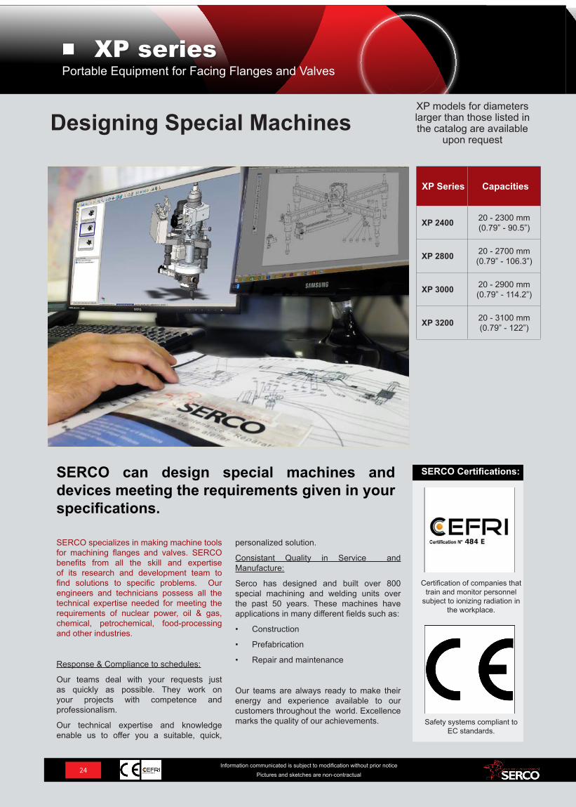
XP models for diameters larger than those listed in the catalog are available
upon request
XP Series Capacities
XP 2400 20 - 2300 mm (0.79” - 90.5”)
XP 2800 20 - 2700 mm (0.79” - 106.3”)
XP 3000 20 - 2900 mm (0.79” - 114.2”)
XP 3200 20 - 3100 mm (0.79” - 122”)
SERCO specializes in making machine tools for machining flanges and valves. SERCO benefits from all the skill and expertise of its research and development team to find solutions to specific problems. Our engineers and technicians possess all the technical expertise needed for meeting the requirements of nuclear power, oil & gas, chemical, petrochemical, food-processing and other industries.
Response & Compliance to schedules:
Our teams deal with your requests just as quickly as possible. They work on your projects with competence and professionalism.
Our technical expertise and knowledge enable us to offer you a suitable, quick,
personalized solution.
Consistant Quality in Service and Manufacture:
Serco has designed and built over 800 special machining and welding units over the past 50 years. These machines have applications in many different fields such as:
• Construction
• Prefabrication
• Repair and maintenance
Our teams are always ready to make their energy and experience available to our customers throughout the world. Excellence marks the quality of our achievements.
SERCO can design special machines and devices meeting the requirements given in your specifications.
Designing Special Machines
Safety systems compliant to EC standards.
Certification of companies that train and monitor personnel
subject to ionizing radiation in the workplace.
SERCO Certifications:
24Information communicated is subject to modification without prior notice
Pictures and sketches are non-contractual
Portable Equipment for Facing Flanges and ValvesXP series
REF. DESCRIPTION
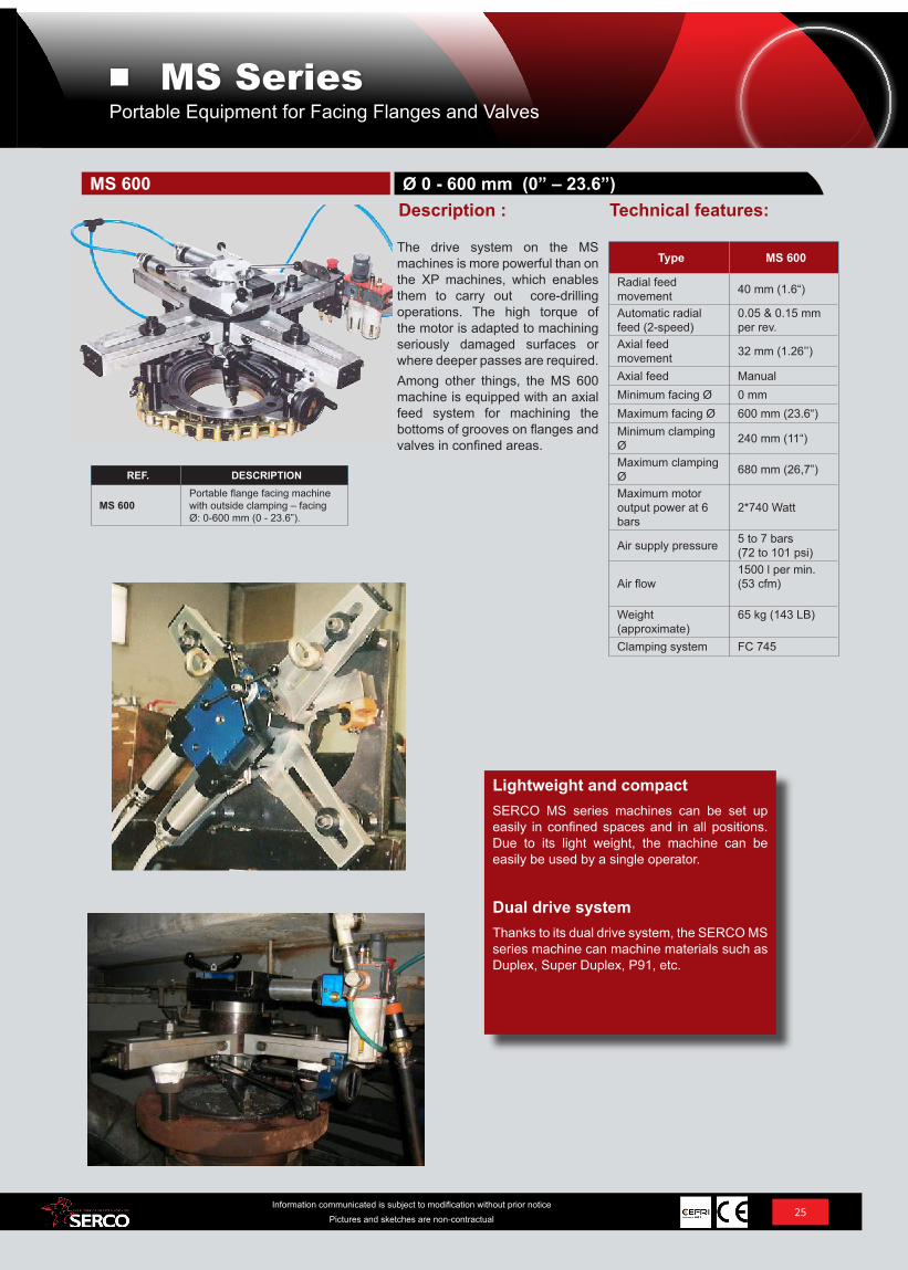
MS 600Portable flange facing machine with outside clamping – facing Ø: 0-600 mm (0 - 23.6”).
Type MS 600
Radial feed movement 40 mm (1.6“)
Automatic radial feed (2-speed)
0.05 & 0.15 mm per rev.
Axial feed movement 32 mm (1.26’’)
Axial feed ManualMinimum facing Ø 0 mmMaximum facing Ø 600 mm (23.6“)Minimum clamping Ø 240 mm (11“)
Maximum clamping Ø 680 mm (26,7”)
Maximum motor output power at 6 bars
2*740 Watt
Air supply pressure 5 to 7 bars(72 to 101 psi)
Air flow1500 l per min. (53 cfm)
Weight (approximate)
65 kg (143 LB)
Clamping system FC 745
Technical features:
Lightweight and compactSERCO MS series machines can be set up easily in confined spaces and in all positions. Due to its light weight, the machine can be easily be used by a single operator.
Dual drive systemThanks to its dual drive system, the SERCO MS series machine can machine materials such as Duplex, Super Duplex, P91, etc.
The drive system on the MS machines is more powerful than on the XP machines, which enables them to carry out core-drilling operations. The high torque of the motor is adapted to machining seriously damaged surfaces or where deeper passes are required.Among other things, the MS 600 machine is equipped with an axial feed system for machining the bottoms of grooves on flanges and valves in confined areas.
Description :Ø 0 - 600 mm (0” – 23.6”)MS 600
25Information communicated is subject to modification without prior notice
Pictures and sketches are non-contractual
Portable Equipment for Facing Flanges and ValvesMS Series
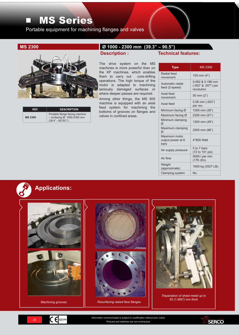
Trepanation of sheet metal up to 50 (1.968”) mm thick
Resurfacing raised face flanges
REF. DESCRIPTION
MS 2300Portable flange facing machine – surfacing Ø: 1000-2300 mm (39.4” - 90.551”).
Type MS 2300
Radial feed movement 100 mm (4“)
Automatic radial feed (2-speed)
0.062 & 0.186 mm (.002” & .007”) per revolution
Axial feed movement 50 mm (2”)
Axial feed 0.08 mm (.003”)per rev.
Minimum facing Ø 1000 mm (39”)Maximum facing Ø 2300 mm (91“)Minimum clamping Ø 1250 mm (49“)
Maximum clamping Ø 2500 mm (98”)
Maximum motor output power at 6 bars
4*900 Watt
Air supply pressure 5 to 7 bars(72 to 101 psi)
Air flow 5000 l per min (176 cfm)
Weight (approximate) 1600 kg (3527 LB)
Clamping system No
Technical features:Ø 1000 - 2300 mm (39.3” – 90.5”)MS 2300
Description :
The drive system on the MS machines is more powerful than on the XP machines, which enables them to carry out core-drilling operations. The high torque of the motor is adapted to machining seriously damaged surfaces or where deeper passes are required.Among other things, the MS 600 machine is equipped with an axial feed system for machining the bottoms of grooves on flanges and valves in confined areas.
26Information communicated is subject to modification without prior notice
Pictures and sketches are non-contractual
Applications:
Machining grooves
Portable equipment for machining flanges and valvesMS Series
27Information communicated is subject to modification without prior notice
Pictures and sketches are non-contractual
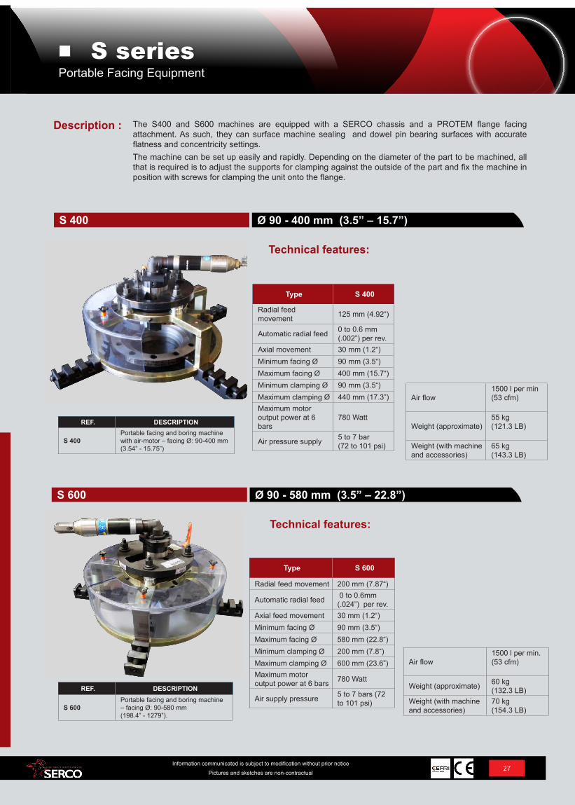
The S400 and S600 machines are equipped with a SERCO chassis and a PROTEM flange facing attachment. As such, they can surface machine sealing and dowel pin bearing surfaces with accurate flatness and concentricity settings.The machine can be set up easily and rapidly. Depending on the diameter of the part to be machined, all that is required is to adjust the supports for clamping against the outside of the part and fix the machine in position with screws for clamping the unit onto the flange.
REF. DESCRIPTION
S 400Portable facing and boring machine with air-motor – facing Ø: 90-400 mm (3.54” - 15.75”)
Type S 400
Radial feed movement 125 mm (4.92“)
Automatic radial feed 0 to 0.6 mm (.002”) per rev.
Axial movement 30 mm (1.2“)Minimum facing Ø 90 mm (3.5“)Maximum facing Ø 400 mm (15.7“)Minimum clamping Ø 90 mm (3.5“)Maximum clamping Ø 440 mm (17.3”)Maximum motor output power at 6 bars
780 Watt
Air pressure supply 5 to 7 bar (72 to 101 psi)
REF. DESCRIPTION
S 600Portable facing and boring machine – facing Ø: 90-580 mm (198.4” - 1279”).
Type S 600
Radial feed movement 200 mm (7.87“)
Automatic radial feed 0 to 0.6mm (.024”) per rev.
Axial feed movement 30 mm (1.2“)Minimum facing Ø 90 mm (3.5“)Maximum facing Ø 580 mm (22.8“)Minimum clamping Ø 200 mm (7.8“)Maximum clamping Ø 600 mm (23.6”)Maximum motor output power at 6 bars 780 Watt
Air supply pressure 5 to 7 bars (72 to 101 psi)
Technical features:
Ø 90 - 580 mm (3.5” – 22.8”)S 600
Air flow1500 l per min (53 cfm)
Weight (approximate)55 kg (121.3 LB)
Weight (with machine and accessories)
65 kg (143.3 LB)
Air flow1500 l per min. (53 cfm)
Weight (approximate) 60 kg (132.3 LB)
Weight (with machine and accessories)
70 kg (154.3 LB)
Technical features:
Description :
Ø 90 - 400 mm (3.5” – 15.7”)S 400
Portable Facing EquipmentS series
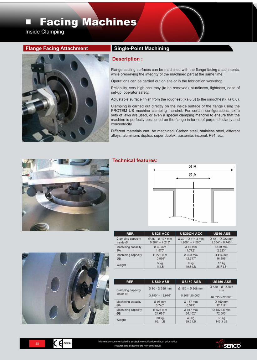
REF. US25-ACC US30CH-ACC US40-ASBClamping capacityInside Ø
Ø 25 – Ø 107 mm0.984” – 4.213”
Ø 32 – Ø 114,3 mm 1.260” – 4.500”
Ø 42 - Ø 222 mm1.654” – 8.740”
Machining capacity ØA
Ø 40 mm1.575”
Ø 45 mm1.772”
Ø 59 mm2.323”
Machining capacity ØB
Ø 276 mm10.866”
Ø 323 mm12.717”
Ø 414 mm16.299”
Weight 5 kg11 LB
9 kg19,8 LB
13 kg28,7 LB
REF. US80-ASB US150-ASB US450-ASB
Clamping capacityInside Ø
Ø 80 - Ø 355 mm
3.150” – 13.976”
Ø 150 – Ø 508 mm
5.906” 20.000”
Ø 420 – Ø 1828.8 mm
16.535” -72.000”Machining capacity ØA
Ø 95 mm3.740”
Ø 167 mm6.575”
Ø 450 mm17.717”
Machining capacity ØB
Ø 627 mm24.685”
Ø 917 mm36.102”
Ø 1828.8 mm72.000”
Weight 30 kg66.1 LB
45 kg 99.2 LB
65 kg 143.3 LB
Flange sealing surfaces can be machined with the flange facing attachments, while preserving the integrity of the machined part at the same time.
Operations can be carried out on site or in the fabrication workshop.
Reliability, very high accuracy (to be removed), sturdiness, lightness, ease of set-up, operator safety.
Adjustable surface finish from the roughest (Ra 6.3) to the smoothest (Ra 0.8).
Clamping is carried out directly on the inside surface of the flange using the PROTEM US machine clamping mandrel. For certain configurations, extra sets of jaws are used, or even a special clamping mandrel to ensure that the machine is perfectly positioned on the flange in terms of perpendicularity and concentricity.
Different materials can be machined: Carbon steel, stainless steel, different alloys, aluminum, duplex, super duplex, austenite, inconel, P91, etc.
Technical features:
Description :
Single-Point MachiningFlange Facing Attachment
Inside Clamping Facing Machines
Ø A
Ø B
28Information communicated is subject to modification without prior notice
Pictures and sketches are non-contractual
Facing Machines
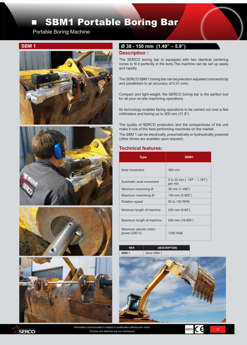
The SERCO boring bar is equipped with two identical centering cones to fit it perfectly in the bore.The machine can be set up easily and rapidly.
The SERCO SBM 1 boring bar can be precision adjusted (concentricity and parallelism to an accuracy of 0.01 mm).
Compact and light-weight, the SERCO boring bar is the perfect tool for all your on-site machining operations.
Its technology enables facing operations to be carried out over a few millimeters and boring up to 300 mm (11.8”).
The quality of SERCO production and the compactness of the unit make it one of the best-performing machines on the market.The SBM 1 can be electrically, pneumatically or hydraulically powered (other drives are availabe upon request).
Description :Ø 38 - 150 mm (1.49” – 5.9”)
REF. DESCRIPTION
SBM 1 Borer SBM 1
SBM 1
Type SBM1
Axial movement 300 mm
Automatic axial movement 5 to 30 mm ( .197” - 1.181”)per min
Minimum machining Ø 38 mm (1.496”)
Maximum machining Ø 150 mm (5.905”)
Rotation speed 50 to 150 RPM
Minimum length of machine 250 mm (9.84”)
Maximum length of machine 500 mm (19.685”)
Maximum electric motor power (230 V) 1300 Watt
Technical features:
29Information communicated is subject to modification without prior notice
Pictures and sketches are non-contractual
Portable Boring MachineSBM1 Portable Boring Bar
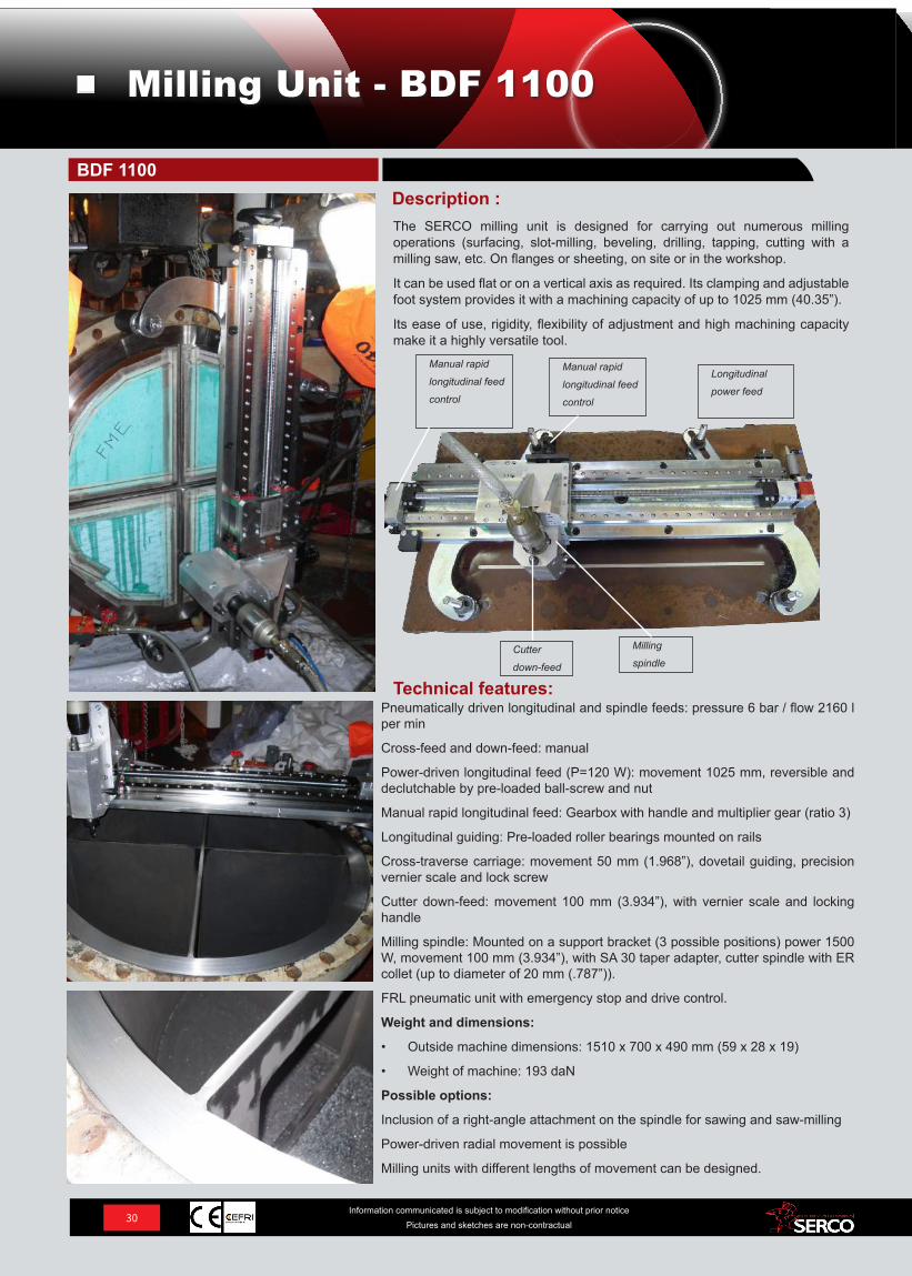
The SERCO milling unit is designed for carrying out numerous milling operations (surfacing, slot-milling, beveling, drilling, tapping, cutting with a milling saw, etc. On flanges or sheeting, on site or in the workshop.
It can be used flat or on a vertical axis as required. Its clamping and adjustable foot system provides it with a machining capacity of up to 1025 mm (40.35”).
Its ease of use, rigidity, flexibility of adjustment and high machining capacity make it a highly versatile tool.
Technical features:
Description :
Pneumatically driven longitudinal and spindle feeds: pressure 6 bar / flow 2160 l per min
Cross-feed and down-feed: manual
Power-driven longitudinal feed (P=120 W): movement 1025 mm, reversible and declutchable by pre-loaded ball-screw and nut
Manual rapid longitudinal feed: Gearbox with handle and multiplier gear (ratio 3)
Longitudinal guiding: Pre-loaded roller bearings mounted on rails
Cross-traverse carriage: movement 50 mm (1.968”), dovetail guiding, precision vernier scale and lock screw
Cutter down-feed: movement 100 mm (3.934”), with vernier scale and locking handle
Milling spindle: Mounted on a support bracket (3 possible positions) power 1500 W, movement 100 mm (3.934”), with SA 30 taper adapter, cutter spindle with ER collet (up to diameter of 20 mm (.787”)).
FRL pneumatic unit with emergency stop and drive control.
Weight and dimensions:
• Outside machine dimensions: 1510 x 700 x 490 mm (59 x 28 x 19)
• Weight of machine: 193 daN
Possible options:
Inclusion of a right-angle attachment on the spindle for sawing and saw-milling
Power-driven radial movement is possible
Milling units with different lengths of movement can be designed.
BDF 1100
30Information communicated is subject to modification without prior notice
Pictures and sketches are non-contractual
Milling Unit - BDF 1100
Manual rapid
longitudinal feed
control
Manual rapid
longitudinal feed
control
Longitudinal
power feed
Cutter
down-feed
Milling
spindle
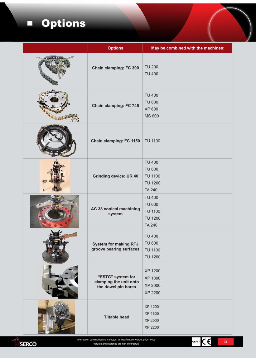
Options May be combined with the machines:
Chain clamping: FC 300 TU 200TU 400
Chain clamping: FC 745
TU 400 TU 600 XP 600MS 600
Chain clamping: FC 1150 TU 1100
Grinding device: UR 40
TU 400TU 600TU 1100TU 1200TA 240
AC 38 conical machining system
TU 400TU 600TU 1100TU 1200 TA 240
System for making RTJ groove bearing surfaces
TU 400TU 600 TU 1100TU 1200
“FSTG” system for clamping the unit onto
the dowel pin bores
XP 1200
XP 1800
XP 2000
XP 2200
Tiltable head
XP 1200
XP 1800
XP 2000
XP 2200
31Information communicated is subject to modification without prior notice
Pictures and sketches are non-contractual
Options
REF. DESCRIPTION
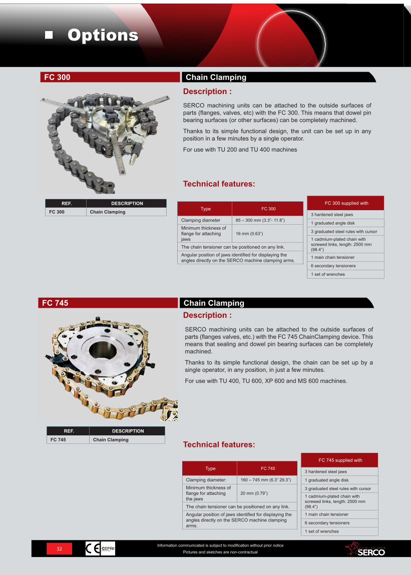
FC 300 Chain Clamping
REF. DESCRIPTION
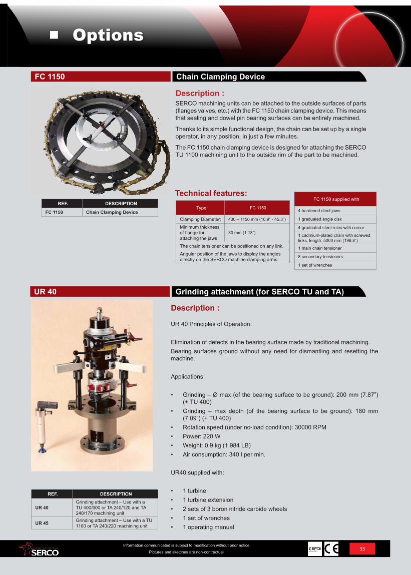
FC 745 Chain Clamping
Type FC 745
Clamping diameter: 160 – 745 mm (6.3” 29.3”)
Minimum thickness of flange for attaching the jaws
20 mm (0.79”)
The chain tensioner can be positioned on any link.Angular position of jaws identified for displaying the angles directly on the SERCO machine clamping arms.
SERCO machining units can be attached to the outside surfaces of parts (flanges valves, etc.) with the FC 745 ChainClamping device. This means that sealing and dowel pin bearing surfaces can be completely machined.
Thanks to its simple functional design, the chain can be set up by a single operator, in any position, in just a few minutes.
For use with TU 400, TU 600, XP 600 and MS 600 machines.
Technical features:
Description :Chain ClampingFC 745
FC 745 supplied with
3 hardened steel jaws
1 graduated angle disk
3 graduated steel rules with cursor
1 cadmium-plated chain with screwed links, length: 2500 mm (98.4”)
1 main chain tensioner
6 secondary tensioners
1 set of wrenches
Type FC 300
Clamping diameter 85 – 300 mm (3.3”- 11.8”)
Minimum thickness of flange for attaching jaws
16 mm (0.63”)
The chain tensioner can be positioned on any link.Angular position of jaws identified for displaying the angles directly on the SERCO machine clamping arms.
FC 300 supplied with
3 hardened steel jaws
1 graduated angle disk
3 graduated steel rules with cursor
1 cadmium-plated chain with screwed links, length: 2500 mm (98.4”)
1 main chain tensioner
6 secondary tensioners
1 set of wrenches
Technical features:
Description :SERCO machining units can be attached to the outside surfaces of parts (flanges, valves, etc) with the FC 300. This means that dowel pin bearing surfaces (or other surfaces) can be completely machined.
Thanks to its simple functional design, the unit can be set up in any position in a few minutes by a single operator.
For use with TU 200 and TU 400 machines
Chain ClampingFC 300
32Information communicated is subject to modification without prior notice
Pictures and sketches are non-contractual
Options
REF. DESCRIPTION
UR 40Grinding attachment – Use with a TU 400/600 or TA 240/120 and TA 240/170 machining unit
UR 45 Grinding attachment – Use with a TU 1100 or TA 240/220 machining unit
UR 40 Principles of Operation:
Elimination of defects in the bearing surface made by traditional machining.Bearing surfaces ground without any need for dismantling and resetting the machine.
Applications:
• Grinding – Ø max (of the bearing surface to be ground): 200 mm (7.87”) (+ TU 400)
• Grinding – max depth (of the bearing surface to be ground): 180 mm (7.09”) (+ TU 400)
• Rotation speed (under no-load condition): 30000 RPM• Power: 220 W• Weight: 0.9 kg (1.984 LB)• Air consumption: 340 l per min.
UR40 supplied with:
• 1 turbine• 1 turbine extension• 2 sets of 3 boron nitride carbide wheels• 1 set of wrenches• 1 operating manual
Description :
Grinding attachment (for SERCO TU and TA)UR 40
REF. DESCRIPTION
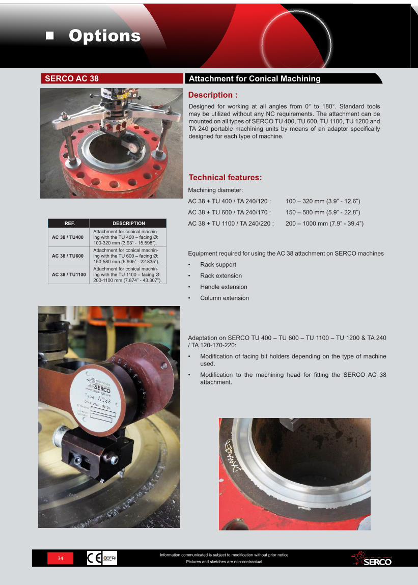
FC 1150 Chain Clamping Device
SERCO machining units can be attached to the outside surfaces of parts (flanges valves, etc.) with the FC 1150 chain clamping device. This means that sealing and dowel pin bearing surfaces can be entirely machined.
Thanks to its simple functional design, the chain can be set up by a single operator, in any position, in just a few minutes.
The FC 1150 chain clamping device is designed for attaching the SERCO TU 1100 machining unit to the outside rim of the part to be machined.
Description :
Chain Clamping DeviceFC 1150
Type FC 1150
Clamping Diameter: 430 – 1150 mm (16.9” - 45.3”)
Minimum thickness of flange for attaching the jaws
30 mm (1.18”)
The chain tensioner can be positioned on any link.Angular position of the jaws to display the angles directly on the SERCO machine clamping arms.
Technical features:FC 1150 supplied with
4 hardened steel jaws
1 graduated angle disk
4 graduated steel rules with cursor
1 cadmium-plated chain with screwed links, length: 5000 mm (196.8”)
1 main chain tensioner
8 secondary tensioners
1 set of wrenches
33Information communicated is subject to modification without prior notice
Pictures and sketches are non-contractual
Options
REF. DESCRIPTION
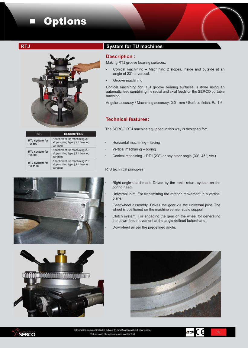
AC 38 / TU400Attachment for conical machin-ing with the TU 400 – facing Ø: 100-320 mm (3.93” - 15.598”).
AC 38 / TU600Attachment for conical machin-ing with the TU 600 – facing Ø: 150-580 mm (5.905” - 22.835”).
AC 38 / TU1100Attachment for conical machin-ing with the TU 1100 – facing Ø: 200-1100 mm (7.874” - 43.307”).
Technical features:
Description :Designed for working at all angles from 0° to 180°. Standard tools may be utilized without any NC requirements. The attachment can be mounted on all types of SERCO TU 400, TU 600, TU 1100, TU 1200 and TA 240 portable machining units by means of an adaptor specifically designed for each type of machine.
Machining diameter:
AC 38 + TU 400 / TA 240/120 : 100 – 320 mm (3.9” - 12.6”)
AC 38 + TU 600 / TA 240/170 : 150 – 580 mm (5.9” - 22.8”)
AC 38 + TU 1100 / TA 240/220 : 200 – 1000 mm (7.9” - 39.4”)
Adaptation on SERCO TU 400 – TU 600 – TU 1100 – TU 1200 & TA 240 / TA 120-170-220:
• Modification of facing bit holders depending on the type of machine used.
• Modification to the machining head for fitting the SERCO AC 38 attachment.
Equipment required for using the AC 38 attachment on SERCO machines
• Rack support
• Rack extension
• Handle extension
• Column extension
Attachment for Conical MachiningSERCO AC 38
34Information communicated is subject to modification without prior notice
Pictures and sketches are non-contractual
Options
REF. DESCRIPTION
RTJ system for TU 400
Attachment for machining 23° slopes (ring type joint bearing surface)
RTJ system for TU 600
Attachment for machining 23° slopes (ring type joint bearing surface)
RTJ system for TU 1100
Attachment for machining 23° slopes (ring type joint bearing surface)
Making RTJ groove bearing surfaces:
• Conical machining – Machining 2 slopes, inside and outside at an angle of 23° to vertical.
• Groove machining
Conical machining for RTJ groove bearing surfaces is done using an automatic feed combining the radial and axial feeds on the SERCO portable machine.
Angular accuracy / Machining accuracy: 0.01 mm / Surface finish: Ra 1.6.
Description :
System for TU machinesRTJ
Technical features:
The SERCO RTJ machine equipped in this way is designed for:
• Horizontal machining – facing
• Vertical machining – boring
• Conical machining – RTJ (23°) or any other angle (30°, 45°, etc.)
RTJ technical principles:
• Right-angle attachment: Driven by the rapid return system on the boring head.
• Universal joint: For transmitting the rotation movement in a vertical plane.
• Gear/wheel assembly: Drives the gear via the universal joint. The wheel is positioned on the machine vernier scale support.
• Clutch system: For engaging the gear on the wheel for generating the down-feed movement at the angle defined beforehand.
• Down-feed as per the predefined angle.
35Information communicated is subject to modification without prior notice
Pictures and sketches are non-contractual
Options
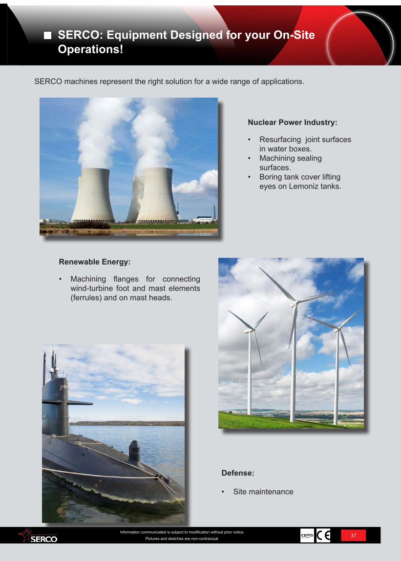
REF. DESCRIPTION
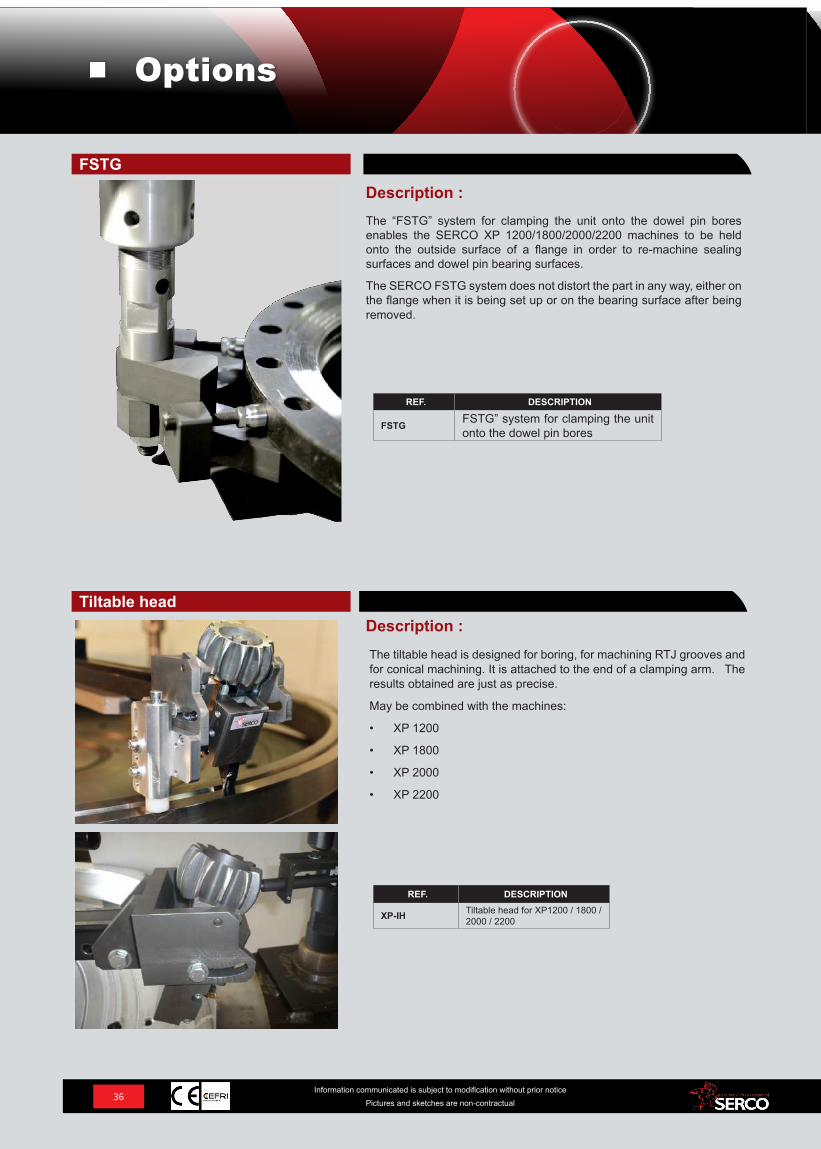
FSTG FSTG” system for clamping the unit onto the dowel pin bores
REF. DESCRIPTION
XP-IH Tiltable head for XP1200 / 1800 / 2000 / 2200
The tiltable head is designed for boring, for machining RTJ grooves and for conical machining. It is attached to the end of a clamping arm. The results obtained are just as precise.
May be combined with the machines:
• XP 1200
• XP 1800
• XP 2000
• XP 2200
Description :Tiltable head
Description :The “FSTG” system for clamping the unit onto the dowel pin bores enables the SERCO XP 1200/1800/2000/2200 machines to be held onto the outside surface of a flange in order to re-machine sealing surfaces and dowel pin bearing surfaces.
The SERCO FSTG system does not distort the part in any way, either on the flange when it is being set up or on the bearing surface after being removed.
FSTG
36Information communicated is subject to modification without prior notice
Pictures and sketches are non-contractual
Options
37Information communicated is subject to modification without prior notice
Pictures and sketches are non-contractual
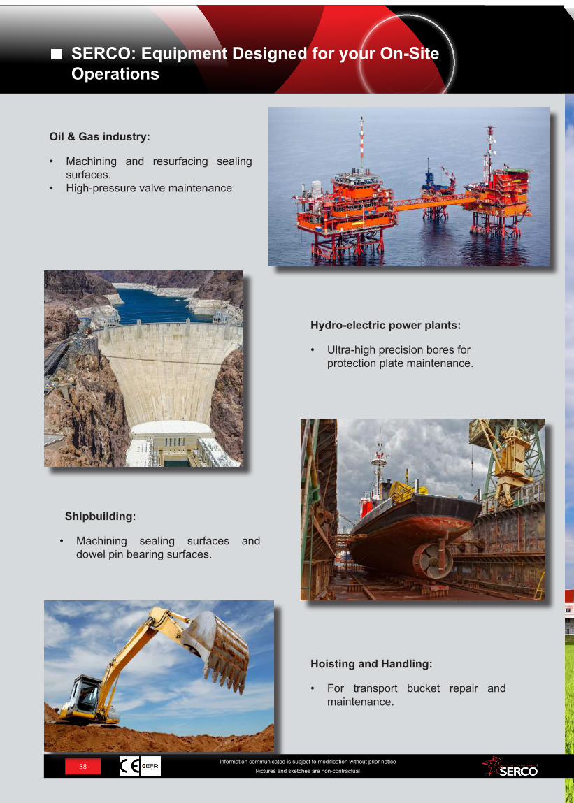
SERCO machines represent the right solution for a wide range of applications.
Nuclear Power Industry:
• Resurfacing joint surfaces in water boxes.
• Machining sealing surfaces.
• Boring tank cover lifting eyes on Lemoniz tanks.
Defense:
• Site maintenance
Renewable Energy:
• Machining flanges for connecting wind-turbine foot and mast elements (ferrules) and on mast heads.
SERCO: Equipment Designed for your On-Site Operations!
38Information communicated is subject to modification without prior notice
Pictures and sketches are non-contractual
Hoisting and Handling:
• For transport bucket repair and maintenance.
Shipbuilding:
• Machining sealing surfaces and dowel pin bearing surfaces.
Hydro-electric power plants:
• Ultra-high precision bores for protection plate maintenance.
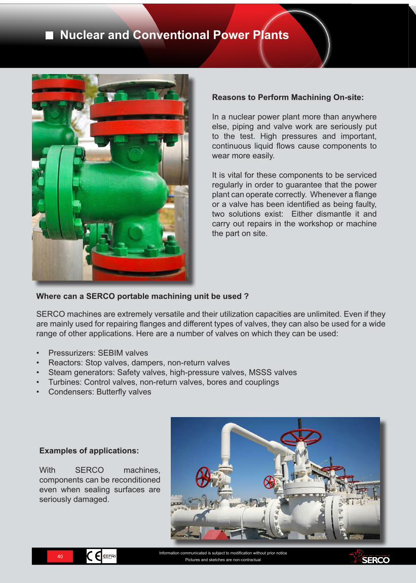
Oil & Gas industry:
• Machining and resurfacing sealing surfaces.
• High-pressure valve maintenance
SERCO: Equipment Designed for your On-Site Operations

NUCLEAR AND CONVENTIONAL POWER PLANTS
39Information communicated is subject to modification without prior notice
Pictures and sketches are non-contractual
Nuclear and Conventional Power Plants
40Information communicated is subject to modification without prior notice
Pictures and sketches are non-contractual
Where can a SERCO portable machining unit be used ?
SERCO machines are extremely versatile and their utilization capacities are unlimited. Even if they are mainly used for repairing flanges and different types of valves, they can also be used for a wide range of other applications. Here are a number of valves on which they can be used:
• Pressurizers: SEBIM valves• Reactors: Stop valves, dampers, non-return valves• Steam generators: Safety valves, high-pressure valves, MSSS valves• Turbines: Control valves, non-return valves, bores and couplings• Condensers: Butterfly valves
Reasons to Perform Machining On-site:
In a nuclear power plant more than anywhere else, piping and valve work are seriously put to the test. High pressures and important, continuous liquid flows cause components to wear more easily.
It is vital for these components to be serviced regularly in order to guarantee that the power plant can operate correctly. Whenever a flange or a valve has been identified as being faulty, two solutions exist: Either dismantle it and carry out repairs in the workshop or machine the part on site.
Examples of applications:
With SERCO machines, components can be reconditioned even when sealing surfaces are seriously damaged.
Nuclear and Conventional Power Plants
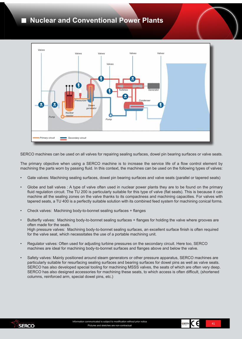
Primary circuit Secondary circuit
PumpPump
Nuclear reactor
Pressurizer
Steam generator
Turbines Generator
Condenser
ValvesValves Valves
Valves
Valves Valves
41Information communicated is subject to modification without prior notice
Pictures and sketches are non-contractual
SERCO machines can be used on all valves for repairing sealing surfaces, dowel pin bearing surfaces or valve seats.
The primary objective when using a SERCO machine is to increase the service life of a flow control element by machining the parts worn by passing fluid. In this context, the machines can be used on the following types of valves:
• Gate valves: Machining sealing surfaces, dowel pin bearing surfaces and valve seats (parallel or tapered seats)
• Globe and ball valves : A type of valve often used in nuclear power plants they are to be found on the primary fluid regulation circuit. The TU 200 is particularly suitable for this type of valve (flat seats). This is because it can machine all the sealing zones on the valve thanks to its compactness and machining capacities. For valves with tapered seats, a TU 400 is a perfectly suitable solution with its combined feed system for machining conical forms.
• Check valves: Machining body-to-bonnet sealing surfaces + flanges
• Butterfly valves: Machining body-to-bonnet sealing surfaces + flanges for holding the valve where grooves are often made for the seals. High pressure valves: Machining body-to-bonnet sealing surfaces, an excellent surface finish is often required for the valve seat, which necessitates the use of a portable machining unit.
• Regulator valves: Often used for adjusting turbine pressures on the secondary circuit. Here too, SERCO machines are ideal for machining body-to-bonnet surfaces and flanges above and below the valve.
• Safety valves: Mainly positioned around steam generators or other pressure apparatus, SERCO machines are particularly suitable for resurfacing sealing surfaces and bearing surfaces for dowel pins as well as valve seats. SERCO has also developed special tooling for machining MSSS valves, the seats of which are often very deep. SERCO has also designed accessories for machining these seats, to which access is often difficult, (shortened columns, reinforced arm, special dowel pins, etc.)
Nuclear and Conventional Power Plants
OIL & GAS
42Information communicated is subject to modification without prior notice
Pictures and sketches are non-contractual
Oil & Gas
43Information communicated is subject to modification without prior notice
Pictures and sketches are non-contractual
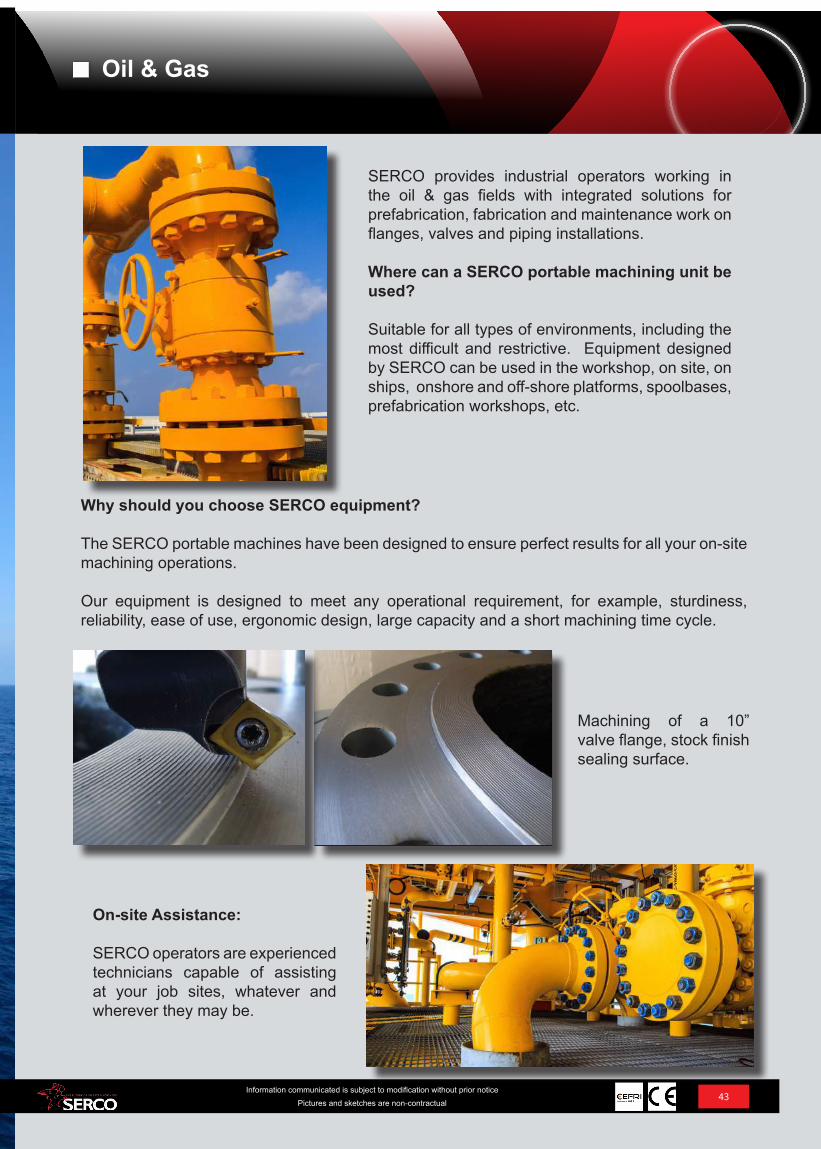
SERCO provides industrial operators working in the oil & gas fields with integrated solutions for prefabrication, fabrication and maintenance work on flanges, valves and piping installations.
Where can a SERCO portable machining unit be used?
Suitable for all types of environments, including the most difficult and restrictive. Equipment designed by SERCO can be used in the workshop, on site, on ships, onshore and off-shore platforms, spoolbases, prefabrication workshops, etc.
Why should you choose SERCO equipment?
The SERCO portable machines have been designed to ensure perfect results for all your on-site machining operations.
Our equipment is designed to meet any operational requirement, for example, sturdiness, reliability, ease of use, ergonomic design, large capacity and a short machining time cycle.
On-site Assistance:
SERCO operators are experienced technicians capable of assisting at your job sites, whatever and wherever they may be.
Machining of a 10” valve flange, stock finish sealing surface.
Oil & Gas
SHIP-BUILDING DEFENSE
44Information communicated is subject to modification without prior notice
Pictures and sketches are non-contractual
Ship-building - Defense
45Information communicated is subject to modification without prior notice
Pictures and sketches are non-contractual
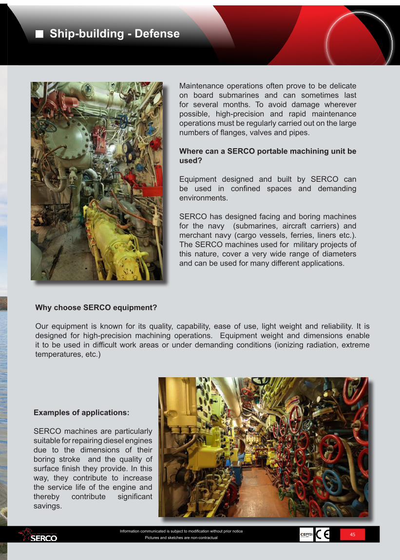
Maintenance operations often prove to be delicate on board submarines and can sometimes last for several months. To avoid damage wherever possible, high-precision and rapid maintenance operations must be regularly carried out on the large numbers of flanges, valves and pipes.
Where can a SERCO portable machining unit be used?
Equipment designed and built by SERCO can be used in confined spaces and demanding environments.
SERCO has designed facing and boring machines for the navy (submarines, aircraft carriers) and merchant navy (cargo vessels, ferries, liners etc.). The SERCO machines used for military projects of this nature, cover a very wide range of diameters and can be used for many different applications.
Why choose SERCO equipment?
Our equipment is known for its quality, capability, ease of use, light weight and reliability. It is designed for high-precision machining operations. Equipment weight and dimensions enable it to be used in difficult work areas or under demanding conditions (ionizing radiation, extreme temperatures, etc.)
Examples of applications:
SERCO machines are particularly suitable for repairing diesel engines due to the dimensions of their boring stroke and the quality of surface finish they provide. In this way, they contribute to increase the service life of the engine and thereby contribute significant savings.
Ship-building - Defense
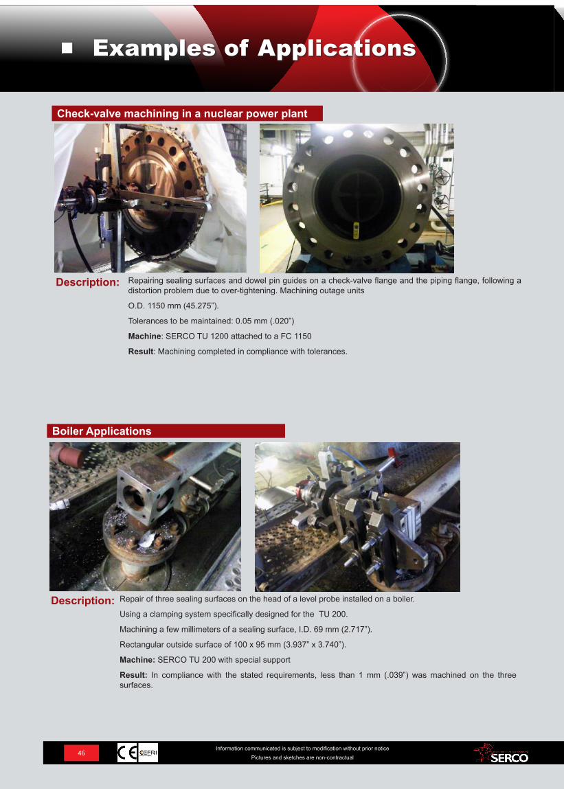
Description: Repairing sealing surfaces and dowel pin guides on a check-valve flange and the piping flange, following a distortion problem due to over-tightening. Machining outage units
O.D. 1150 mm (45.275”).
Tolerances to be maintained: 0.05 mm (.020”)
Machine: SERCO TU 1200 attached to a FC 1150
Result: Machining completed in compliance with tolerances.
Check-valve machining in a nuclear power plant
Description: Repair of three sealing surfaces on the head of a level probe installed on a boiler.
Using a clamping system specifically designed for the TU 200.
Machining a few millimeters of a sealing surface, I.D. 69 mm (2.717”).
Rectangular outside surface of 100 x 95 mm (3.937” x 3.740”).
Machine: SERCO TU 200 with special support
Result: In compliance with the stated requirements, less than 1 mm (.039”) was machined on the three surfaces.
Boiler Applications
46Information communicated is subject to modification without prior notice
Pictures and sketches are non-contractual
Examples of Applications
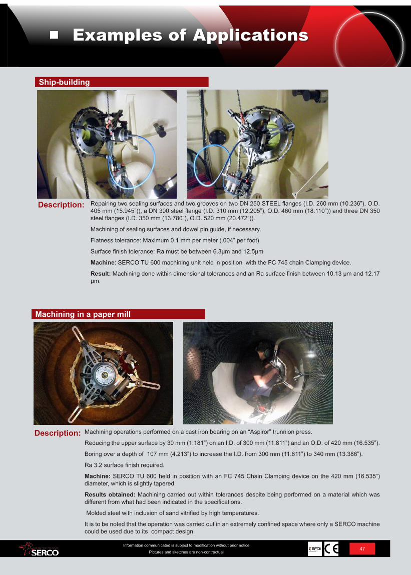
Description: Repairing two sealing surfaces and two grooves on two DN 250 STEEL flanges (I.D. 260 mm (10.236”), O.D. 405 mm (15.945”)), a DN 300 steel flange (I.D. 310 mm (12.205”), O.D. 460 mm (18.110”)) and three DN 350 steel flanges (I.D. 350 mm (13.780”), O.D. 520 mm (20.472”)).
Machining of sealing surfaces and dowel pin guide, if necessary.
Flatness tolerance: Maximum 0.1 mm per meter (.004” per foot).
Surface finish tolerance: Ra must be between 6.3µm and 12.5µm
Machine: SERCO TU 600 machining unit held in position with the FC 745 chain Clamping device.
Result: Machining done within dimensional tolerances and an Ra surface finish between 10.13 µm and 12.17 µm.
Ship-building
Description: Machining operations performed on a cast iron bearing on an “Aspiror” trunnion press.
Reducing the upper surface by 30 mm (1.181”) on an I.D. of 300 mm (11.811”) and an O.D. of 420 mm (16.535”).
Boring over a depth of 107 mm (4.213”) to increase the I.D. from 300 mm (11.811”) to 340 mm (13.386”).
Ra 3.2 surface finish required.
Machine: SERCO TU 600 held in position with an FC 745 Chain Clamping device on the 420 mm (16.535”) diameter, which is slightly tapered.
Results obtained: Machining carried out within tolerances despite being performed on a material which was different from what had been indicated in the specifications.
Molded steel with inclusion of sand vitrified by high temperatures.
It is to be noted that the operation was carried out in an extremely confined space where only a SERCO machine could be used due to its compact design.
Machining in a paper mill
47Information communicated is subject to modification without prior notice
Pictures and sketches are non-contractual
Examples of Applications
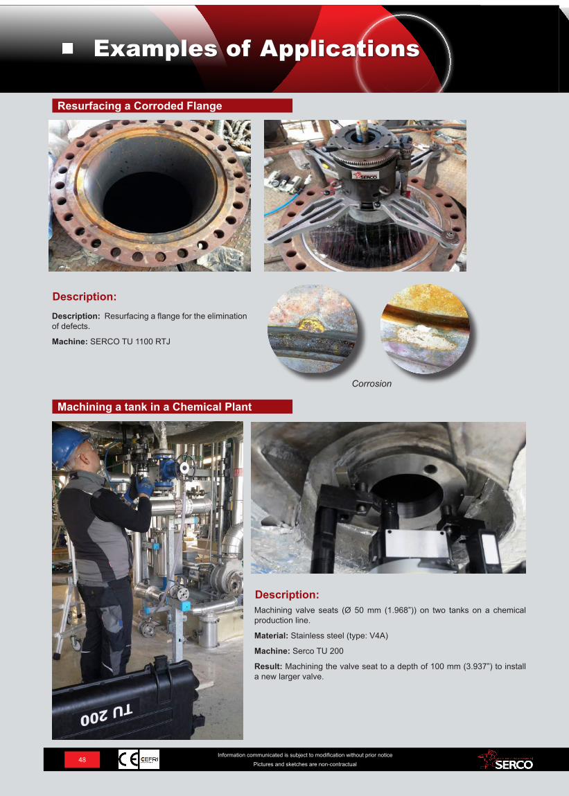
Description:Machining valve seats (Ø 50 mm (1.968”)) on two tanks on a chemical production line.
Material: Stainless steel (type: V4A)
Machine: Serco TU 200
Result: Machining the valve seat to a depth of 100 mm (3.937”) to install a new larger valve.
Machining a tank in a Chemical Plant
Description:Description: Resurfacing a flange for the elimination of defects.
Machine: SERCO TU 1100 RTJ
Resurfacing a Corroded Flange
Corrosion
48Information communicated is subject to modification without prior notice
Pictures and sketches are non-contractual
Examples of Applications
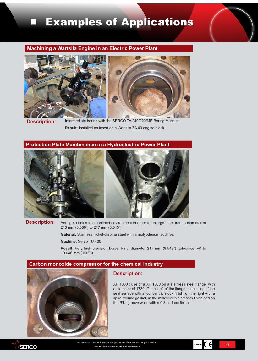
Protection Plate Maintenance in a Hydroelectric Power Plant
Machining a Wartsila Engine in an Electric Power Plant
Boring 40 holes in a confined environment in order to enlarge them from a diameter of 213 mm (8.386”) to 217 mm (8.543”).
Material: Stainless nickel-chrome steel with a molybdenum additive.
Machine: Serco TU 400
Result: Very high-precision bores. Final diameter 217 mm (8.543”) (tolerance: +0 to +0.046 mm (.002”)).
Description:
Intermediate boring with the SERCO TA 240/220/ME Boring Machine.
Result: Installed an insert on a Wartsila ZA 40 engine block.
Carbon monoxide compressor for the chemical industry
Description:
XP 1800 : use of a XP 1800 on a stainless steel flange with a diameter of 1730. On the left of the flange, machining of the seal surface with a concentric stock finish, on the right with a spiral wound gasket, in the middle with a smooth finish and on the RTJ groove walls with a 0,8 surface finish.
Description:
49Information communicated is subject to modification without prior notice
Pictures and sketches are non-contractual
Examples of Applications
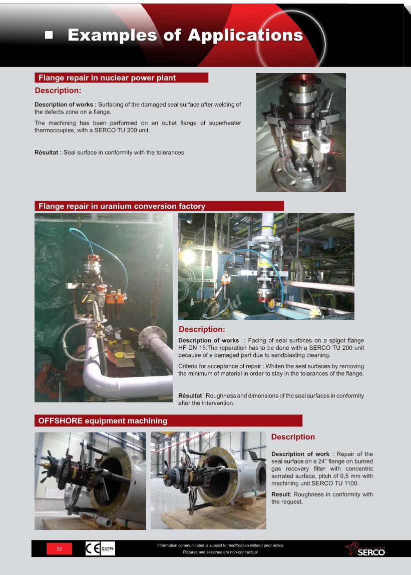
Description:Description of works : Facing of seal surfaces on a spigot flange HF DN 15.The reparation has to be done with a SERCO TU 200 unit because of a damaged part due to sandblasting cleaning.
Criteria for acceptance of repair : Whiten the seal surfaces by removing the minimum of material in order to stay in the tolerances of the flange.
Résultat : Roughness and dimensions of the seal surfaces in conformity after the intervention.
Flange repair in uranium conversion factory
OFFSHORE equipment machining
Description
Description of work : Repair of the seal surface on a 24” flange on burned gas recovery filter with concentric serrated surface, pitch of 0,5 mm with machining unit SERCO TU 1100.
Result: Roughness in conformity with the request.
Description:Description of works : Surfacing of the damaged seal surface after welding of the defects zone on a flange.
The machining has been performed on an outlet flange of superheater thermocouples, with a SERCO TU 200 unit.
Résultat : Seal surface in conformity with the tolerances
Flange repair in nuclear power plant
50Information communicated is subject to modification without prior notice
Pictures and sketches are non-contractual
Examples of Applications
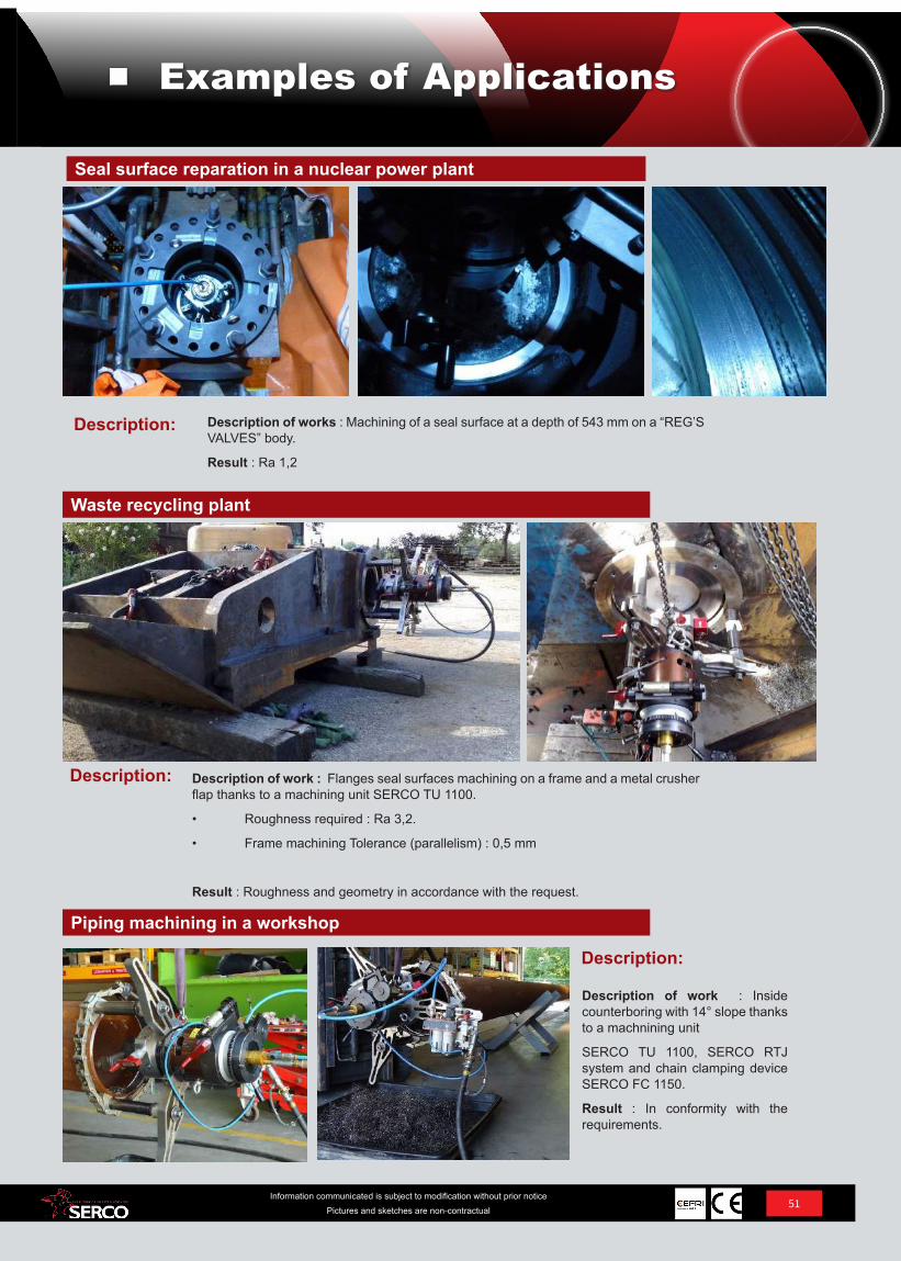
Waste recycling plant
Seal surface reparation in a nuclear power plant
Description of work : Flanges seal surfaces machining on a frame and a metal crusher flap thanks to a machining unit SERCO TU 1100.
• Roughness required : Ra 3,2.
• Frame machining Tolerance (parallelism) : 0,5 mm
Result : Roughness and geometry in accordance with the request.
Description:
Description of works : Machining of a seal surface at a depth of 543 mm on a “REG’S VALVES” body.
Result : Ra 1,2
Piping machining in a workshop
Description:
Description of work : Inside counterboring with 14° slope thanks to a machnining unit
SERCO TU 1100, SERCO RTJ system and chain clamping device SERCO FC 1150.
Result : In conformity with the requirements.
Description:
51Information communicated is subject to modification without prior notice
Pictures and sketches are non-contractual
Examples of Applications
52Information communicated is subject to modification without prior notice
Pictures and sketches are non-contractual
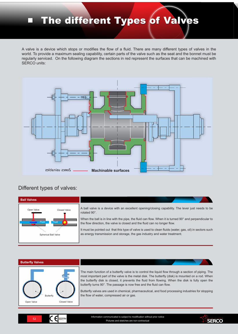
Machinable surfaces
The main function of a butterfly valve is to control the liquid flow through a section of piping. The most important part of the valve is the metal disk. The butterfly (disk) is mounted on a rod. When the butterfly disk is closed, it prevents the fluid from flowing. When the disk is fully open the butterfly turns 90°. The passage is now free and the fluid can flow.
Butterfly valves are used in chemical, pharmaceutical, and food processing industries for stopping the flow of water, compressed air or gas.
A ball valve is a device with an excellent opening/closing capability. The lever just needs to be rotated 90°.
When the ball is in line with the pipe, the fluid can flow. When it is turned 90° and perpendicular to the flow direction, the valve is closed and the fluid can no longer flow.
It must be pointed out that this type of valve is used to clean fluids (water, gas, oil) in sectors such as energy transmission and storage, the gas industry and water treatment.
Ball Valves
Butterfly Valves
Different types of valves:
A valve is a device which stops or modifies the flow of a fluid. There are many different types of valves in the world. To provide a maximum sealing capability, certain parts of the valve such as the seat and the bonnet must be regularly serviced. On the following diagram the sections in red represent the surfaces that can be machined with SERCO units:
The different Types of Valves
Fluid Fluid
Open Valve Closed Valve
Butterfly
Spherical Ball Valve
Open Valve Closed Valve
53Information communicated is subject to modification without prior notice
Pictures and sketches are non-contractual
The different Types of Valves
The diaphragm (made of rubber or plastic) pushed down by the bonnet makes contact with the valve seat and forms a seal.
This type of valve is ideal for controlling the flow of fluid that contains solids in suspension as well as corrosive or abrasive fluids. Initially, diaphragm valves were developed for industrial applications. Later, their design was modified for use in the pharmaceutical industry using materials capable of resisting different methods of disinfection and sterilization.
In a seat valve, the fluid flow is regulated by the valve door being fully closed or open. When the valve is closed, the door is completely shut and no fluid can flow through. On the other hand, when the valve is open, the door is raised, which means that nothing can prevent the fluid from flowing through. This type of valve is used in a large number of industries, particularly food processing and pharmaceutical. They are ideal for liquid fluids.
This type of valve is suitable for adjusting fluid flows. Pressure retaining valves are operated by a hand wheel. When the gate is pushed tightly against the valve seat, the valve is closed. When the gate is not held against the seat, the valve is open.
The valve rod must be rotated frequently for opening and closing the valve. As a result, the seal is often prematurely worn.
Pressure retaining valves are suitable for a wide range of applications from flow regulation to no-flow conditions.
The purpose of throttle valves is to limit the flow of a fluid (Venturi effect) and in this way accelerate its speed when leaving the valve.
These types of valves are specifically designed for the oil and gas industry in order to control the flow of oil coming from the substratum via the wells.
Oil wells require regular maintenance (facing) for their throttle valves due to the erosion phenom-ena that occur as a result of extreme conditions (especially low temperatures).
Throttle Valves
Diaphragm Valves
Seat Valves
Pressure Retaining Valves
Non-return or check valves enable fluids to circulate one way only and they close automatically to prevent any back-flow (which avoids gas blow-backs for instance).
The degree to which the non-return valve opens depends on the flow. The higher the flow, the more the valve is open. If the pressure increases down the line from the valve and is higher than the pressure up the line from the valve, the system closes automatically.
Non-return valves are more often used in nuclear power plants due to their light weight and compact design. They can also be used underwater in difficult and restrictive conditions and in the presence of very high pressure and low temperatures.
Non-Return Valves
Fluid Fluid
Fluid
Open valves Closed Valves
Closed valvesOpen valves
Closed valvesOpen valves
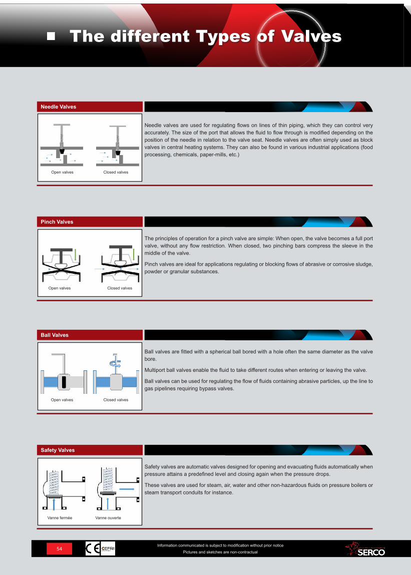
54Information communicated is subject to modification without prior notice
Pictures and sketches are non-contractual
The principles of operation for a pinch valve are simple: When open, the valve becomes a full port valve, without any flow restriction. When closed, two pinching bars compress the sleeve in the middle of the valve.
Pinch valves are ideal for applications regulating or blocking flows of abrasive or corrosive sludge, powder or granular substances.
Ball valves are fitted with a spherical ball bored with a hole often the same diameter as the valve bore.
Multiport ball valves enable the fluid to take different routes when entering or leaving the valve.
Ball valves can be used for regulating the flow of fluids containing abrasive particles, up the line to gas pipelines requiring bypass valves.
Safety valves are automatic valves designed for opening and evacuating fluids automatically when pressure attains a predefined level and closing again when the pressure drops.
These valves are used for steam, air, water and other non-hazardous fluids on pressure boilers or steam transport conduits for instance.
Needle valves are used for regulating flows on lines of thin piping, which they can control very accurately. The size of the port that allows the fluid to flow through is modified depending on the position of the needle in relation to the valve seat. Needle valves are often simply used as block valves in central heating systems. They can also be found in various industrial applications (food processing, chemicals, paper-mills, etc.)
Needle Valves
Pinch Valves
Ball Valves
Safety Valves
The different Types of Valves
Open valves Closed valves
Closed valves
Closed valves
Vanne ouverte
Open valves
Open valves
Vanne fermée
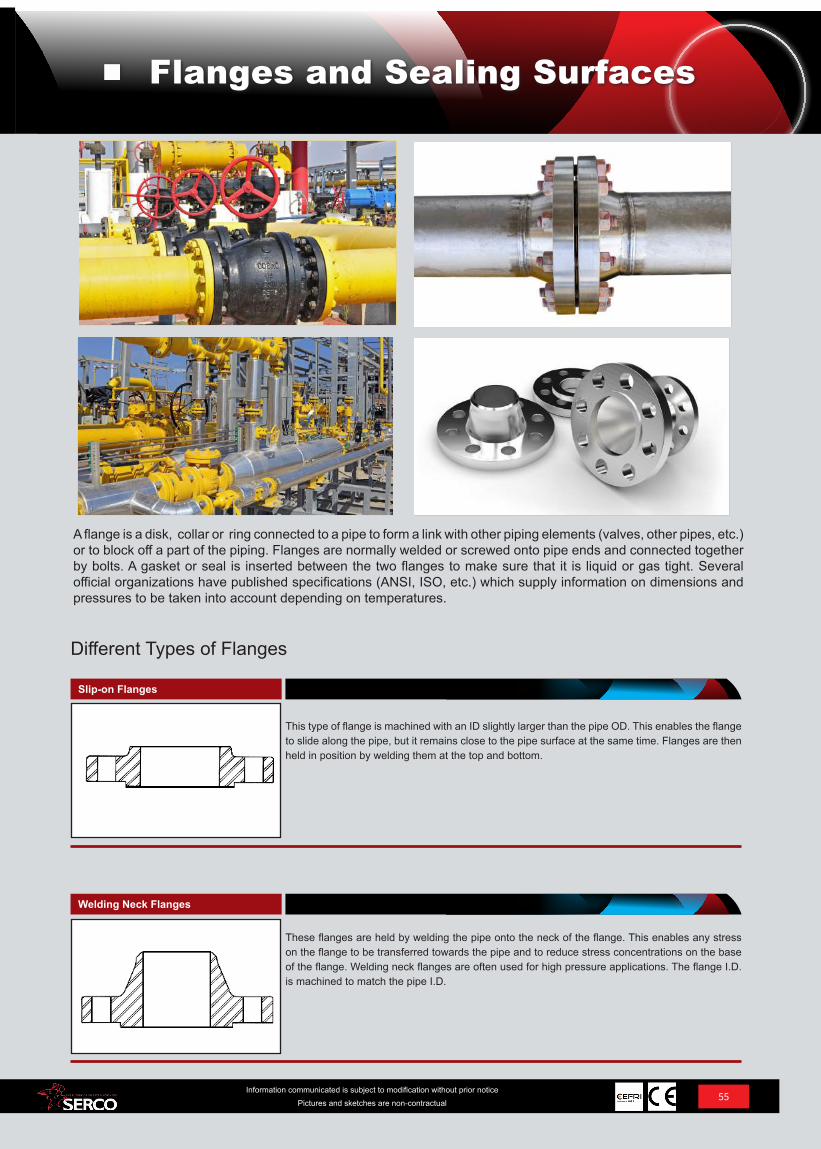
These flanges are held by welding the pipe onto the neck of the flange. This enables any stress on the flange to be transferred towards the pipe and to reduce stress concentrations on the base of the flange. Welding neck flanges are often used for high pressure applications. The flange I.D. is machined to match the pipe I.D.
This type of flange is machined with an ID slightly larger than the pipe OD. This enables the flange to slide along the pipe, but it remains close to the pipe surface at the same time. Flanges are then held in position by welding them at the top and bottom.
Slip-on Flanges
Welding Neck Flanges
Different Types of Flanges
A flange is a disk, collar or ring connected to a pipe to form a link with other piping elements (valves, other pipes, etc.) or to block off a part of the piping. Flanges are normally welded or screwed onto pipe ends and connected together by bolts. A gasket or seal is inserted between the two flanges to make sure that it is liquid or gas tight. Several official organizations have published specifications (ANSI, ISO, etc.) which supply information on dimensions and pressures to be taken into account depending on temperatures.
55Information communicated is subject to modification without prior notice
Pictures and sketches are non-contractual
Flanges and Sealing Surfaces
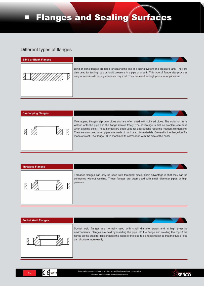
Overlapping flanges slip onto pipes and are often used with collared pipes. The collar or rim is welded onto the pipe and the flange rotates freely. The advantage is that no problem can arise when aligning bolts. These flanges are often used for applications requiring frequent dismantling. They are also used when pipes are made of hard or exotic materials. Generally, the flange itself is made of steel. The flange I.D. is machined to correspond with the size of the collar.
Threaded flanges can only be used with threaded pipes. Their advantage is that they can be connected without welding. These flanges are often used with small diameter pipes at high pressure.
Socket weld flanges are normally used with small diameter pipes and in high pressure environments. Flanges are held by inserting the pipe into the flange and welding the top of the flange on the outside. This enables the inside of the pipe to be kept smooth so that the fluid or gas can circulate more easily.
Blind or blank flanges are used for sealing the end of a piping system or a pressure tank. They are also used for testing gas or liquid pressure in a pipe or a tank. This type of flange also provides easy access inside piping whenever required. They are used for high pressure applications.
Blind or Blank Flanges
Overlapping Flanges
Threaded Flanges
Socket Weld Flanges
56Information communicated is subject to modification without prior notice
Pictures and sketches are non-contractual
Different types of flanges
Flanges and Sealing Surfaces
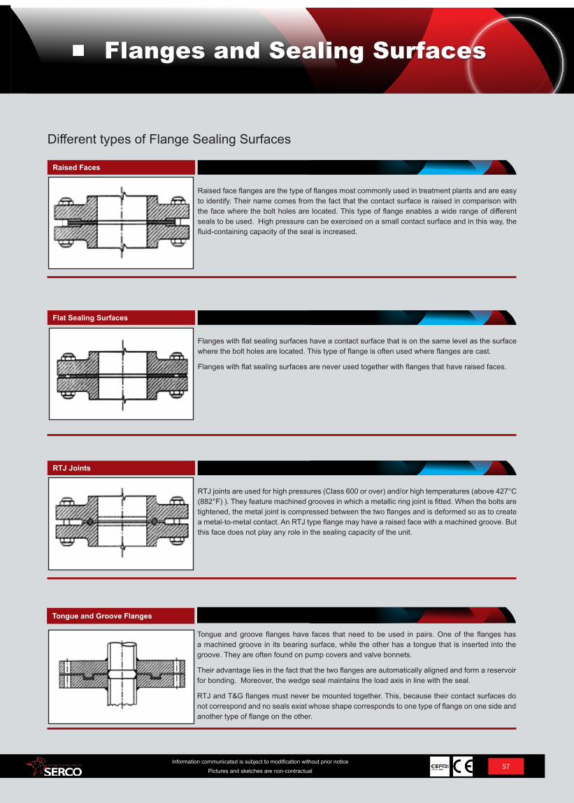
Raised face flanges are the type of flanges most commonly used in treatment plants and are easy to identify. Their name comes from the fact that the contact surface is raised in comparison with the face where the bolt holes are located. This type of flange enables a wide range of different seals to be used. High pressure can be exercised on a small contact surface and in this way, the fluid-containing capacity of the seal is increased.
Flanges with flat sealing surfaces have a contact surface that is on the same level as the surface where the bolt holes are located. This type of flange is often used where flanges are cast.
Flanges with flat sealing surfaces are never used together with flanges that have raised faces.
RTJ joints are used for high pressures (Class 600 or over) and/or high temperatures (above 427°C (882°F) ). They feature machined grooves in which a metallic ring joint is fitted. When the bolts are tightened, the metal joint is compressed between the two flanges and is deformed so as to create a metal-to-metal contact. An RTJ type flange may have a raised face with a machined groove. But this face does not play any role in the sealing capacity of the unit.
Tongue and groove flanges have faces that need to be used in pairs. One of the flanges has a machined groove in its bearing surface, while the other has a tongue that is inserted into the groove. They are often found on pump covers and valve bonnets.
Their advantage lies in the fact that the two flanges are automatically aligned and form a reservoir for bonding. Moreover, the wedge seal maintains the load axis in line with the seal.
RTJ and T&G flanges must never be mounted together. This, because their contact surfaces do not correspond and no seals exist whose shape corresponds to one type of flange on one side and another type of flange on the other.
Raised Faces
Flat Sealing Surfaces
RTJ Joints
Tongue and Groove Flanges
57Information communicated is subject to modification without prior notice
Pictures and sketches are non-contractual
Different types of Flange Sealing Surfaces
Flanges and Sealing Surfaces
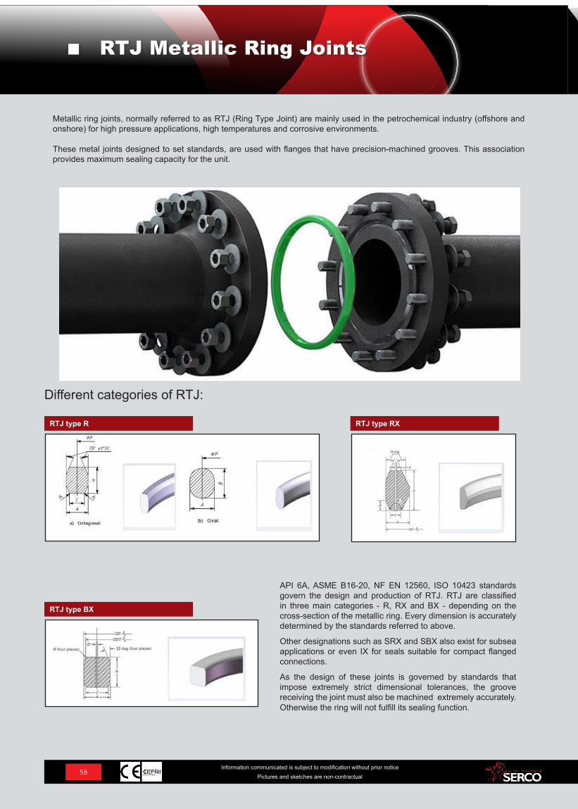
58Information communicated is subject to modification without prior notice
Pictures and sketches are non-contractual
RTJ type R RTJ type RX
Different categories of RTJ:
Metallic ring joints, normally referred to as RTJ (Ring Type Joint) are mainly used in the petrochemical industry (offshore and onshore) for high pressure applications, high temperatures and corrosive environments.
These metal joints designed to set standards, are used with flanges that have precision-machined grooves. This association provides maximum sealing capacity for the unit.
RTJ Metallic Ring Joints
RTJ type BX
API 6A, ASME B16-20, NF EN 12560, ISO 10423 standards govern the design and production of RTJ. RTJ are classified in three main categories - R, RX and BX - depending on the cross-section of the metallic ring. Every dimension is accurately determined by the standards referred to above.
Other designations such as SRX and SBX also exist for subsea applications or even IX for seals suitable for compact flanged connections.
As the design of these joints is governed by standards that impose extremely strict dimensional tolerances, the groove receiving the joint must also be machined extremely accurately. Otherwise the ring will not fulfill its sealing function.
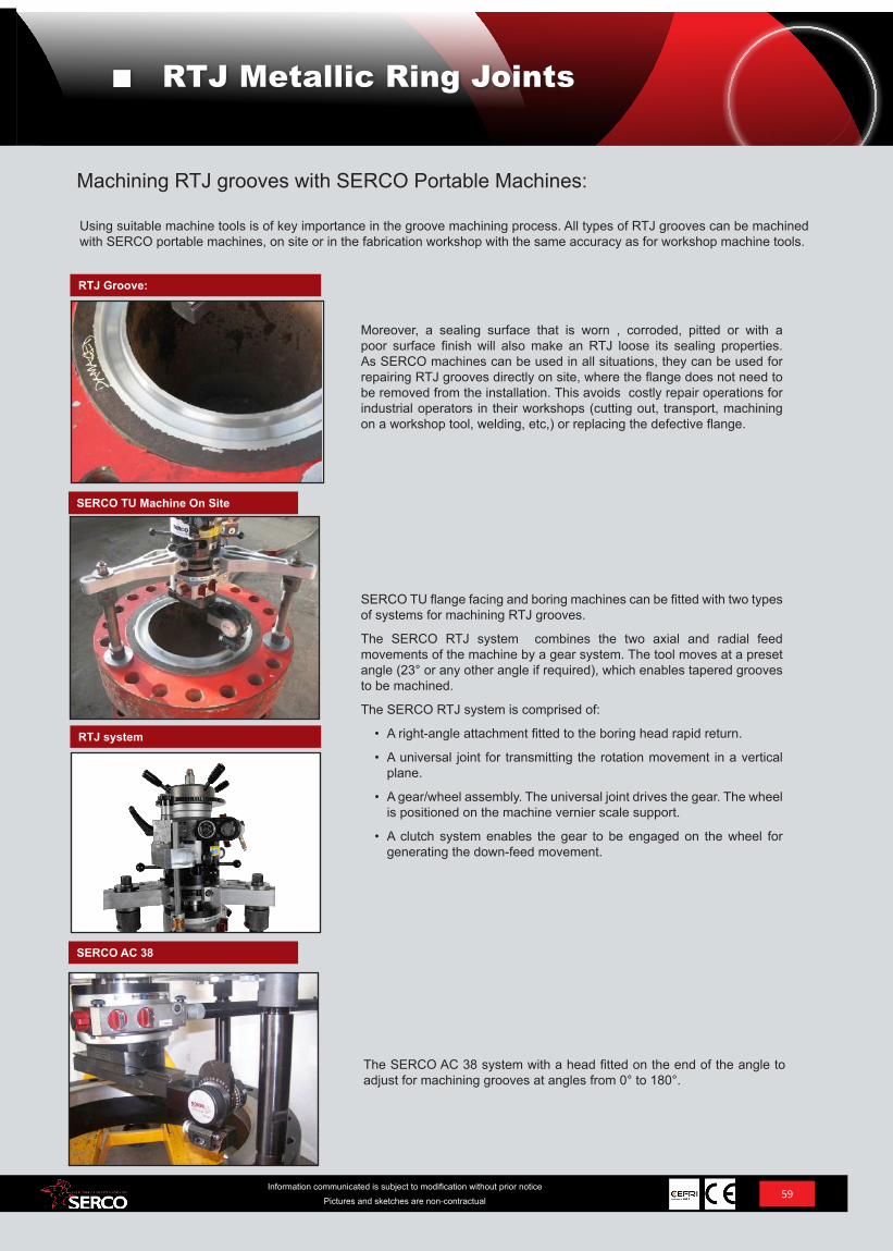
59Information communicated is subject to modification without prior notice
Pictures and sketches are non-contractual
RTJ Metallic Ring Joints
Moreover, a sealing surface that is worn , corroded, pitted or with a poor surface finish will also make an RTJ loose its sealing properties. As SERCO machines can be used in all situations, they can be used for repairing RTJ grooves directly on site, where the flange does not need to be removed from the installation. This avoids costly repair operations for industrial operators in their workshops (cutting out, transport, machining on a workshop tool, welding, etc,) or replacing the defective flange.
SERCO TU Machine On Site
RTJ Groove:
Machining RTJ grooves with SERCO Portable Machines:
Using suitable machine tools is of key importance in the groove machining process. All types of RTJ grooves can be machined with SERCO portable machines, on site or in the fabrication workshop with the same accuracy as for workshop machine tools.
SERCO AC 38
RTJ system
SERCO TU flange facing and boring machines can be fitted with two types of systems for machining RTJ grooves.
The SERCO RTJ system combines the two axial and radial feed movements of the machine by a gear system. The tool moves at a preset angle (23° or any other angle if required), which enables tapered grooves to be machined.
The SERCO RTJ system is comprised of:
• A right-angle attachment fitted to the boring head rapid return.
• A universal joint for transmitting the rotation movement in a vertical plane.
• A gear/wheel assembly. The universal joint drives the gear. The wheel is positioned on the machine vernier scale support.
• A clutch system enables the gear to be engaged on the wheel for generating the down-feed movement.
The SERCO AC 38 system with a head fitted on the end of the angle to adjust for machining grooves at angles from 0° to 180°.
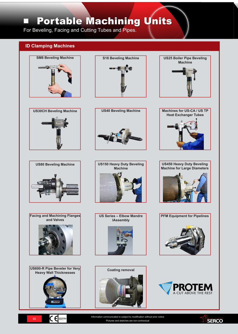
ID Clamping Machines
SM8 Beveling Machine S18 Beveling Machine US25 Boiler Pipe Beveling Machine
US30CH Beveling Machine US40 Beveling Machine Machines for US-CA / US TP Heat Exchanger Tubes
US80 Beveling Machine US150 Heavy Duty Beveling Machine
US450 Heavy Duty Beveling Machine for Large Diameters
Facing and Machining Flanges and Valves
US Series – Elbow Mandre lAssembly
PFM Equipment for Pipelines
US600-R Pipe Beveler for Very Heavy Wall Thicknesses
Coating removal
60Information communicated is subject to modification without prior notice
Pictures and sketches are non-contractual
For Beveling, Facing and Cutting Tubes and Pipes.Portable Machining Units
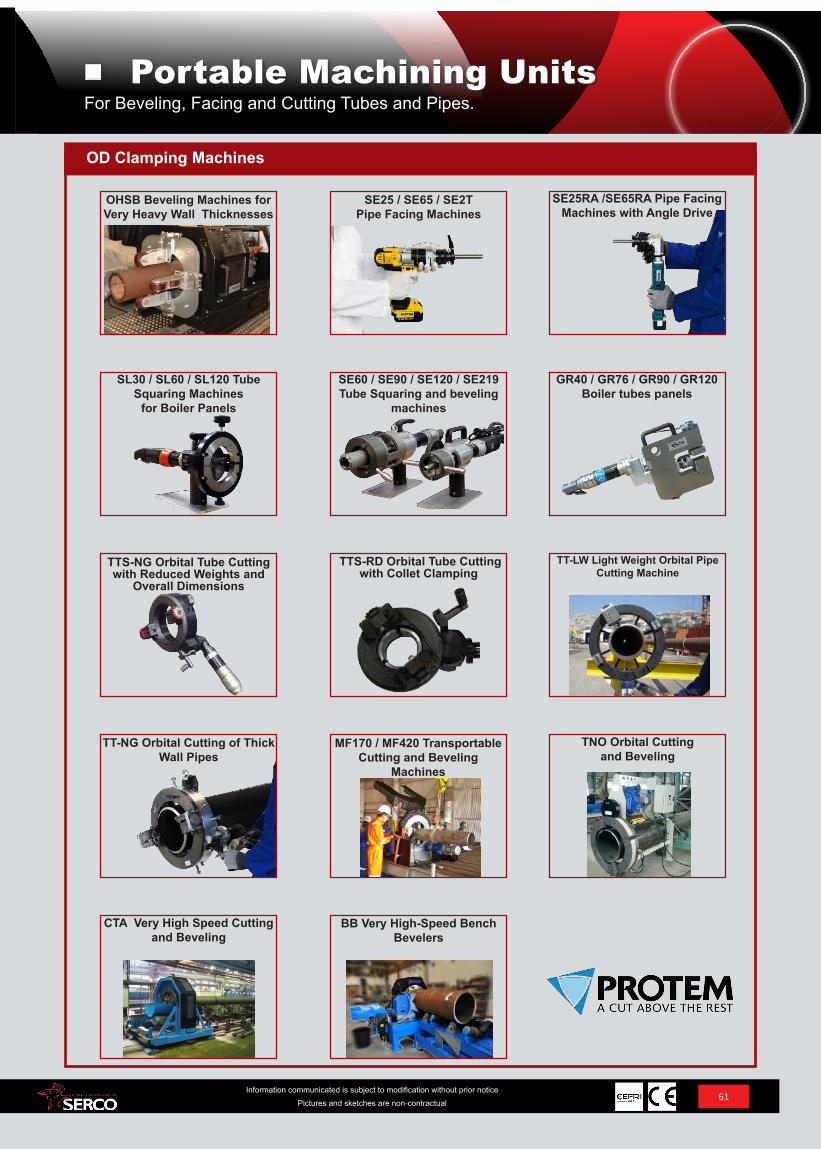
OD Clamping Machines
OHSB Beveling Machines for Very Heavy Wall Thicknesses
SE25 / SE65 / SE2T Pipe Facing Machines
SE25RA /SE65RA Pipe Facing Machines with Angle Drive
SL30 / SL60 / SL120 Tube Squaring Machines
for Boiler Panels
SE60 / SE90 / SE120 / SE219 Tube Squaring and beveling
machines
GR40 / GR76 / GR90 / GR120Boiler tubes panels
TTS-NG Orbital Tube Cutting with Reduced Weights and
Overall Dimensions
TTS-RD Orbital Tube Cutting with Collet Clamping
TT-LW Light Weight Orbital Pipe Cutting Machine
TT-NG Orbital Cutting of Thick Wall Pipes
MF170 / MF420 Transportable Cutting and Beveling
Machines
TNO Orbital Cutting and Beveling
CTA Very High Speed Cutting and Beveling
BB Very High-Speed Bench Bevelers
61Information communicated is subject to modification without prior notice
Pictures and sketches are non-contractual
For Beveling, Facing and Cutting Tubes and Pipes.Portable Machining Units
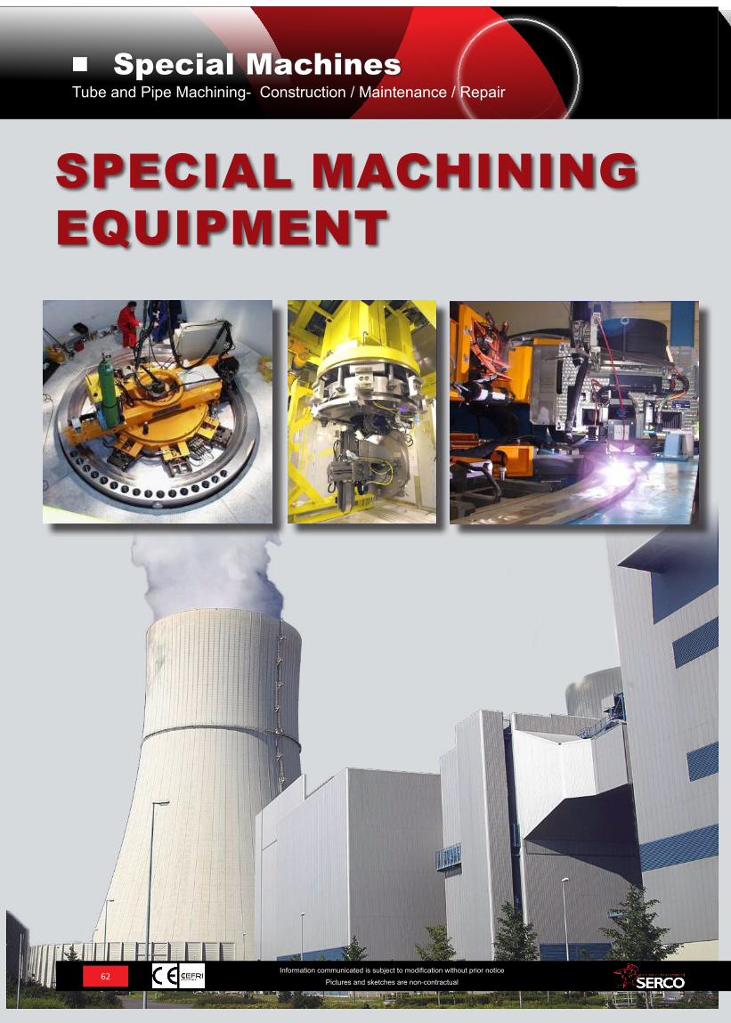
62Information communicated is subject to modification without prior notice
Pictures and sketches are non-contractual
SPECIAL MACHINING EQUIPMENT
Tube and Pipe Machining- Construction / Maintenance / RepairSpecial Machines
63Information communicated is subject to modification without prior notice
Pictures and sketches are non-contractual
SPECIAL MACHINING EQUIPMENT
The SERCO Advantage:
• Responsiveness and the capacity to meet deadlines.
For over 50 years SERCO has been designing and building special units to machine flanges and valves in order to mee tessential technical requirements for specific applications. Our engineers and technicians work with your industrial projects, from equipment design to installation in your workshops or on your job sites.
Our knowledge and expertise are made available to our industrial partners throughout the world. Our engineers and technicians offer you the benefits of their technical expertise and their understanding of major project factors so that they can propose the right solutions.
Expertise – Knowledge - Skills - Quality - Reliability – Industrial Performance
SERCO has designed and built over 1,000 special machines over the last 50 years for applications in different fields, such as;
• Construction• Prefabrication• Maintenance and Repair Nuclear power – Oil & Gas – Chemical – Green Energy – High Purity – Aerospace - Construction – Ship-building – Defense, etc.
• Our Service Offer Includes:
• Planning and modeling operations specific to each project• Technical assistance as project stages progress• Installation of equipment on site• Operator training• Permanent industrial consultation
• Professionalism and Partnership:
Our engineers and technicians benefit from a number of years’ experience in the fields of mechanics, electronics, radiation protection, site organization, constraints related to certain projects, on-site machining, etc.
SERCO commits itself to complying with safety and hygiene obligations concerning the sites where it is working, in any industry, as well as, with the regulations and standards in force in terms of safety and security.
Tube and Pipe Machining- Construction / Maintenance / RepairSpecial Machines
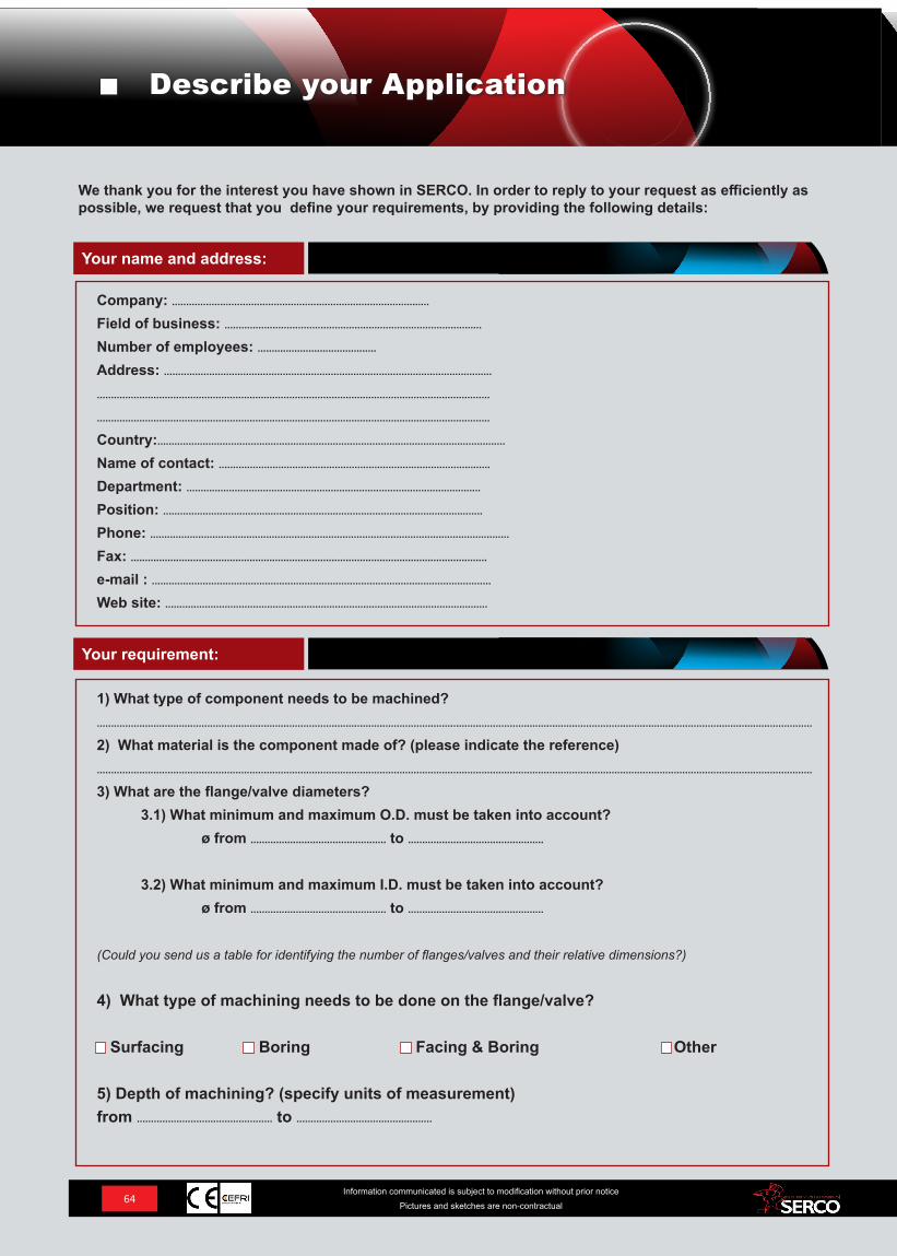
We thank you for the interest you have shown in SERCO. In order to reply to your request as efficiently as possible, we request that you define your requirements, by providing the following details:
Company: ...........................................................................................Field of business: ...........................................................................................Number of employees: .......................................... Address: ...............................................................................................................................................................................................................................................................
........................................................................................................................................... Country:...........................................................................................................................
Name of contact: ................................................................................................ Department: ........................................................................................................ Position: ................................................................................................................. Phone: ...............................................................................................................................Fax: ..............................................................................................................................e-mail : ........................................................................................................................ Web site: ..................................................................................................................
1) What type of component needs to be machined?.............................................................................................................................................................................................................................................................
2) What material is the component made of? (please indicate the reference) .............................................................................................................................................................................................................................................................
3) What are the flange/valve diameters? 3.1) What minimum and maximum O.D. must be taken into account? ø from ................................................ to ................................................
3.2) What minimum and maximum I.D. must be taken into account? ø from ................................................ to ................................................
(Could you send us a table for identifying the number of flanges/valves and their relative dimensions?)
4) What type of machining needs to be done on the flange/valve?
Surfacing Boring Facing & Boring Other
5) Depth of machining? (specify units of measurement)from ................................................ to ................................................
Your requirement:
Your name and address:
64Information communicated is subject to modification without prior notice
Pictures and sketches are non-contractual
Describe your Application
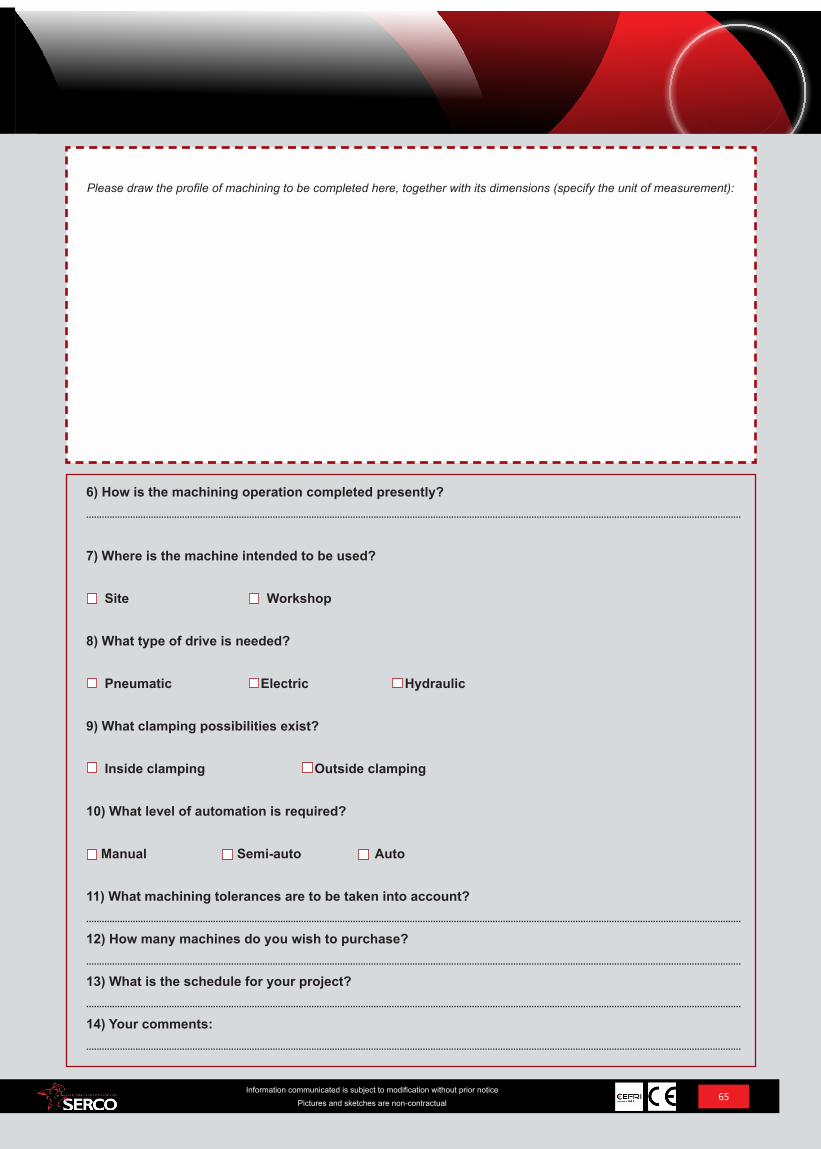
Please draw the profile of machining to be completed here, together with its dimensions (specify the unit of measurement):
6) How is the machining operation completed presently? .............................................................................................................................................................................................................................................................
7) Where is the machine intended to be used?
Site Workshop
8) What type of drive is needed?
Pneumatic Electric Hydraulic
9) What clamping possibilities exist?
Inside clamping Outside clamping
10) What level of automation is required?
Manual Semi-auto Auto
11) What machining tolerances are to be taken into account? .............................................................................................................................................................................................................................................................
12) How many machines do you wish to purchase? .............................................................................................................................................................................................................................................................
13) What is the schedule for your project? .............................................................................................................................................................................................................................................................
14) Your comments:.............................................................................................................................................................................................................................................................
65Information communicated is subject to modification without prior notice
Pictures and sketches are non-contractual
USA 29340 Industrial Way, # 402Evergreen, CO 80439| USAPhone: +1 303 955 4862 Fax: +1 303 955 5904 [email protected] www.serco-usa.com
GermanyAm Hambiegel 2776706 Dettenheim | DEPhone: +49 (0) 7247 9393 – 0Fax: +49 (0) 7247 9393 - 33 [email protected]
SERCO SASFrance 2 Rue de l’ArtisanatZA du Meyrol26200 Montélimar| FRPhone: +33 (0) 4 7501 4298Fax: +33 (0) 4 7501 [email protected]


![PRINOTH MAGAZINE FR | 2016 [2] · 2017. 10. 17. · prinoth magazine fr | 2016 [2] index Édito produits le leitwolf, chef de file de chaque flotte snowpark : l’univers des prinoth](https://img.pdfslide.us/doc/110x75/611c68d3108d5065fb1b956a/prinoth-magazine-fr-2016-2-2017-10-17-prinoth-magazine-fr-2016-2-index.jpg)