Embed Size (px)
Citation preview
Catalogue Mechatronic Basis ProductsIssue 8/2004

Index
Berger Lahr Mechatronic Basis Products 8/2004 3
Drive Solutions . . . . . . . . . . . . . . . . . . . . . . . . . . . . . . Page 5
EC motors . . . . . . . . . . . . . . . . . . . . . . . . . . . . . . . . . . Page 9
2-phase stepping motors . . . . . . . . . . . . . . . . . . . . . . Page 51
Synchronous motors . . . . . . . . . . . . . . . . . . . . . . . . . . Page 73
Geared motors . . . . . . . . . . . . . . . . . . . . . . . . . . . . . . Page 127
Actuators. . . . . . . . . . . . . . . . . . . . . . . . . . . . . . . . . . . Page 129
Berger Lahr's Mechatronic's division develops and produces special drive solutions for many industries, based on the standard products described in this catalogue.
EC motors are electronically commutated synchronous motors, with high power and dynamics.
2-phase stepping motors can be used for precise, simple, and positioning tasks.
Synchronous motors can be connected to a 50 Hz or 60 Hz AC power mains without additional control electronics.
The motors can be delivered with various gear types with numerous variations of transmission.
Actuators can precisely position flaps, valves, or slides.

Printing Industry Applications
Berger Lahr Mechatronic Basis Products 8/2004 5
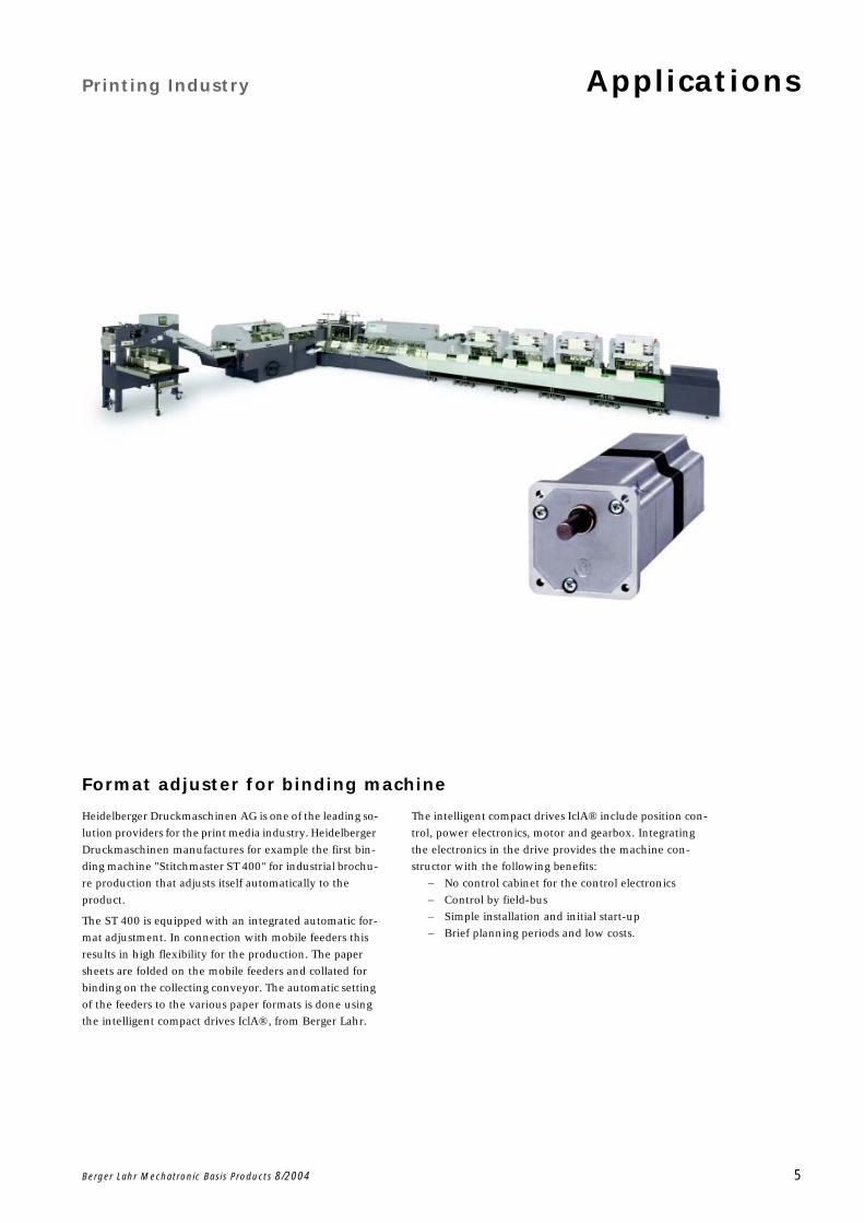
Format adjuster for binding machine
Heidelberger Druckmaschinen AG is one of the leading so-
lution providers for the print media industry. Heidelberger
Druckmaschinen manufactures for example the first bin-
ding machine "Stitchmaster ST 400" for industrial brochu-
re production that adjusts itself automatically to the
product.
The ST 400 is equipped with an integrated automatic for-
mat adjustment. In connection with mobile feeders this
results in high flexibility for the production. The paper
sheets are folded on the mobile feeders and collated for
binding on the collecting conveyor. The automatic setting
of the feeders to the various paper formats is done using
the intelligent compact drives IclA®‚ from Berger Lahr.
The intelligent compact drives IclA® include position con-
trol, power electronics, motor and gearbox. Integrating
the electronics in the drive provides the machine con-
structor with the following benefits:
No control cabinet for the control electronics
Control by field-bus
Simple installation and initial start-up
Brief planning periods and low costs.
Applications Texile Machines
6 Berger Lahr Mechatronic Basis Products 8/2004
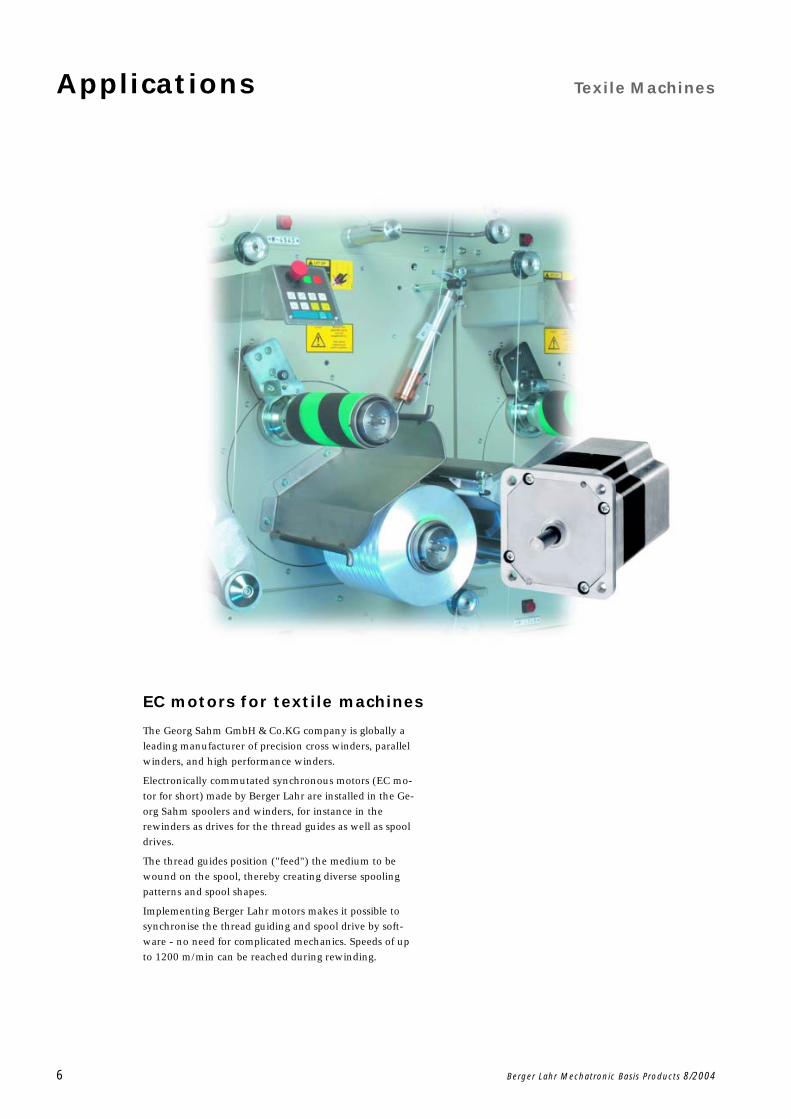
EC motors for textile machines
The Georg Sahm GmbH & Co.KG company is globally a
leading manufacturer of precision cross winders, parallel
winders, and high performance winders.
Electronically commutated synchronous motors (EC mo-
tor for short) made by Berger Lahr are installed in the Ge-
org Sahm spoolers and winders, for instance in the
rewinders as drives for the thread guides as well as spool
drives.
The thread guides position ("feed") the medium to be
wound on the spool, thereby creating diverse spooling
patterns and spool shapes.
Implementing Berger Lahr motors makes it possible to
synchronise the thread guiding and spool drive by soft-
ware - no need for complicated mechanics. Speeds of up
to 1200 m/min can be reached during rewinding.
Heating, Air conditioning, Ventilation Applications
Berger Lahr Mechatronic Basis Products 8/2004 7
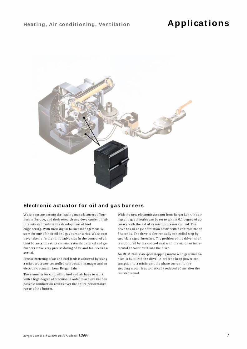
Electronic actuator for oil and gas burners
Weishaupt are among the leading manufacturers of bur-
ners in Europe, and their research and development insti-
tute sets standards in the development of fuel
engineering. With their digital burner management sy-
stem for one of their oil and gas burner series, Weishaupt
have taken a further innovative step in the control of air
blast burners. The strict emissions standards for oil and gas
burners make very precise dosing of air and fuel feeds es-
sential.
Precise metering of air and fuel feeds is achieved by using
a microprocessor-controlled combustion manager and an
electronic actuator from Berger Lahr.
The elements for controlling fuel and air have to work
with a high degree of precision in order to achieve the best
possible combustion results over the entire performance
range of the burner.
With the new electronic actuator from Berger Lahr, the air
flap and gas throttles can be set to within 0.1 degree of ac-
curacy with the aid of its microprocessor control. The
drive has an angle of rotation of 90 with a control time of
3 seconds. The drive is electronically controlled step by
step via a signal interface. The position of the driven shaft
is monitored by the control unit with the aid of an incre-
mental encoder built into the drive.
An RDM 36/6 claw-pole stepping motor with gear mecha-
nism is built into the drive. In order to keep power con-
sumption to a minimum, the phase current to the
stepping motor is automatically reduced 20 ms after the
last step signal.
Applications Medical Engineering
8 Berger Lahr Mechatronic Basis Products 8/2004
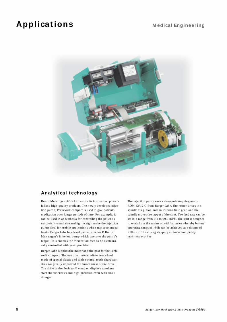
Analytical technology
Braun Melsungen AG is known for its innovative, power-
ful and high-quality products. The newly developed injec-
tion pump, Perfusor® compact is used to give patients
medication over longer periods of time. For example, it
can be used in anaesthesia for controlling the patient's
narcosis. Its small size and light weight make the injection
pump ideal for mobile applications when transporting pa-
tients. Berger Lahr has developed a drive for B.Braun
Melsungen's injection pump which operates the pump's
tappet. This enables the medication feed to be electroni-
cally controlled with great precision.
Berger Lahr supplies the motor and the gear for the Perfu-
sor® compact. The use of an intermediate gearwheel
made of special plastic and with optimal teeth characteri-
stics has greatly improved the smoothness of the drive.
The drive in the Perfusor® compact displays excellent
start characteristics and high precision even with small
dosages.
The injection pump uses a claw-pole stepping motor
RDM 42/12 G from Berger Lahr. The motor drives the
spindle via pinion and an intermediate gear, and the
spindle moves the tappet of the shot. The feed rate can be
set in a range from 0.1 to 99.9 ml/h. The unit is designed
to work from the mains or with batteries whereby battery
operating times of >80h can be achieved at a dosage of
<10ml/h. The dosing stepping motor is completely
maintenance-free.
EC Motors
Berger Lahr Mechatronic Basis Products 8/2004 9
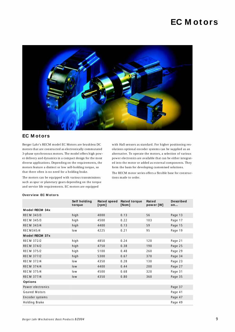
EC Motors
Berger Lahr's RECM model EC Motors are brushless DC
motors that are constructed as electronically commutated
3-phase synchronous motors. The model offers high pow-
er delivery and dynamics in a compact design for the most
diverse applications. Depending on the requirements, the
motors feature a distinct or low self-holding torque, so
that there often is no need for a holding brake.
The motors can be equipped with various transmissions
such as spur or planetary gears depending on the torque
and service life requirements. EC motors are equipped
with Hall sensors as standard. For higher positioning res-
olutions optional encoder systems can be supplied as an
alternative. To operate the motors, a selection of various
power electronics are available that can be either integrat-
ed into the motor or added as external components. They
form the basis for developing customised solutions.
The RECM motor series offers a flexible base for construc-
tions made to order.
Overview EC Motors
Self holding torque
Rated speed [rpm]
Rated torque [Ncm]
Rated power [W]
Described on...
Model RECM 34x
RECM 343/3 high 4000 0.13 56 Page 13
RECM 345/3 high 4500 0.22 103 Page 17
RECM 343/4 high 4400 0.13 59 Page 15
RECM345/4 low 4225 0.21 95 Page 19
Model RECM 37x
RECM 372/2 high 4850 0.24 120 Page 21
RECM 374/2 high 4750 0.38 190 Page 25
RECM 375/2 high 5100 0.48 260 Page 29
RECM 377/2 high 5300 0.67 370 Page 34
RECM 372/4 low 4350 0.28 130 Page 23
RECM 374/4 low 4400 0.44 200 Page 27
RECM 375/4 low 4500 0.68 320 Page 31
RECM 377/4 low 4350 0.80 360 Page 35
Options
Power electronics Page 37
Geared Motors Page 41
Encoder systems Page 47
Holding Brake Page 49
EC Motors General
10 Berger Lahr Mechatronic Basis Products 8/2004
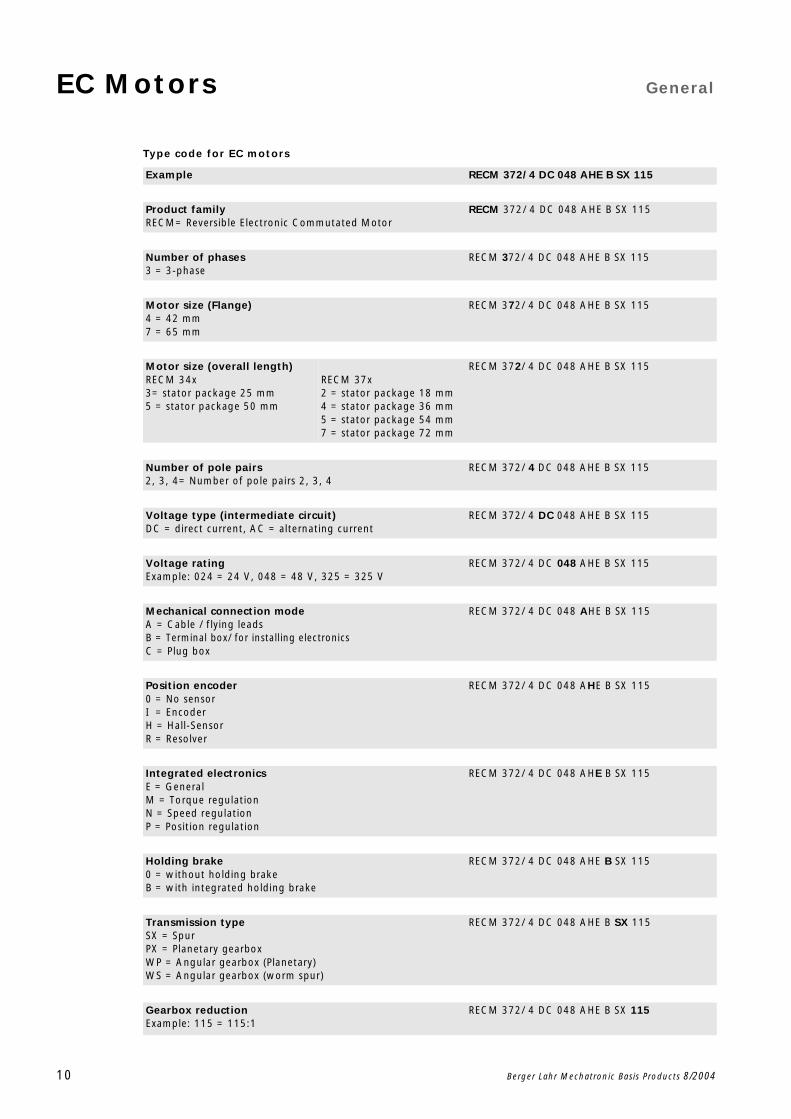
Type code for EC motors
Example RECM 372/ 4 DC 048 AHE B SX 115
Product familyRECM= Reversible Electronic Commutated Motor
RECM 372/ 4 DC 048 AHE B SX 115
Number of phases3 = 3-phase
RECM 372/ 4 DC 048 AHE B SX 115
Motor size (Flange)4 = 42 mm7 = 65 mm
RECM 372/ 4 DC 048 AHE B SX 115
Motor size (overall length)RECM 34x3= stator package 25 mm5 = stator package 50 mm
RECM 37x2 = stator package 18 mm4 = stator package 36 mm5 = stator package 54 mm7 = stator package 72 mm
RECM 372/ 4 DC 048 AHE B SX 115
Number of pole pairs2, 3, 4= Number of pole pairs 2, 3, 4
RECM 372/ 4 DC 048 AHE B SX 115
Voltage type (intermediate circuit)DC = direct current, AC = alternating current
RECM 372/ 4 DC 048 AHE B SX 115
Voltage ratingExample: 024 = 24 V, 048 = 48 V, 325 = 325 V
RECM 372/ 4 DC 048 AHE B SX 115
Mechanical connection modeA = Cable / flying leadsB = Terminal box/ for installing electronicsC = Plug box
RECM 372/ 4 DC 048 AHE B SX 115
Position encoder0 = No sensorI = EncoderH = Hall-SensorR = Resolver
RECM 372/ 4 DC 048 AHE B SX 115
Integrated electronicsE = GeneralM = Torque regulationN = Speed regulationP = Position regulation
RECM 372/ 4 DC 048 AHE B SX 115
Holding brake0 = without holding brakeB = with integrated holding brake
RECM 372/ 4 DC 048 AHE B SX 115
Transmission typeSX = SpurPX = Planetary gearboxWP = Angular gearbox (Planetary)WS = Angular gearbox (worm spur)
RECM 372/ 4 DC 048 AHE B SX 115
Gearbox reductionExample: 115 = 115:1
RECM 372/ 4 DC 048 AHE B SX 115
General EC Motors
Berger Lahr Mechatronic Basis Products 8/2004 11
General technical information
Self-holding torque
In standard versions, the RECM 34x EC motors with
3 pole pairs come with high, and those with 4 pole pairs
with low self-holding torque.
RECM 37x EC motors with 2 pole pairs come with high,
and those with 4 pole pairs with low self-holding torque
in their standard versions.
A different self-holding torque can be supplied on request
by means of non-standard magnetisation of the rotor.
Temperatures
The permissible ambient temperatures range from -25 °C
to +40 °C. If heat dissipation is normal, then additional
ventilation of the motors is not necessary. If ambient tem-
peratures exceeds 40° C, then the permitted load on the
motor is reduced.
Connection type
The EC motor 34x features connectors and the 37x fea-
tures flying leads in their standard versions.
Voltage dimensioning
The EC motors can be supplied in various spooling varia-
tions for different voltages. Special spooling variations are
available on request.

EC Motors
12 Berger Lahr Mechatronic Basis Products 8/2004
Technical Data EC MotorsRECM 343/3
Berger Lahr Mechatronic Basis Products 8/2004 13
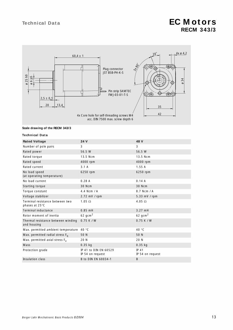
Scale drawing of the RECM 343/3
Technical Data
Rated Voltage 24 V 48 V
Number of pole pairs 3 3
Rated power 56.5 W 56.5 W
Rated torque 13.5 Ncm 13.5 Ncm
Rated speed 4000 rpm 4000 rpm
Rated current 3.1 A 1.55 A
No load speed (at operating temperature)
6250 rpm 6250 rpm
No load current 0.28 A 0.14 A
Starting torque 30 Ncm 30 Ncm
Torque constant 4.4 Ncm / A 8.7 Ncm / A
Voltage stabilizer 2.72 mV / rpm 5.33 mV / rpm
Terminal resistance between two phases at 25C
1.05 4.05
Terminal inductance 0.85 mH 3.27 mH
Rotor moment of inertia 62 gcm2 62 gcm2
Thermal resistance between winding and housing
0.75 K / W 0.75 K / W
Max. permitted ambient temperature 40 C 40 C
Max. permitted radial stress Fq 50 N 50 N
Max. permitted axial stress Fa 20 N 20 N
Mass 0.35 kg 0.35 kg
Protection grade IP 41 to DIN EN 60529 IP 54 on request
IP 41IP 54 on request
Insulation class B to DIN EN 60034-1 B
4x Core hole for self-threading screws M4acc. DIN 7500 max. screw depth 6
4x ø 4,2
35
42
80˚
3x
20˚
ø 34
Pin strip SAMTECFWJ-03-01-T-S
Plug connectorJST B5B-PH-K-S
ø 25
h9
ø 6
js5
60,4 ± 1
20
2,5 ± 0,1
13,4
EC Motors Technical Data
RECM 343/3
14 Berger Lahr Mechatronic Basis Products 8/2004
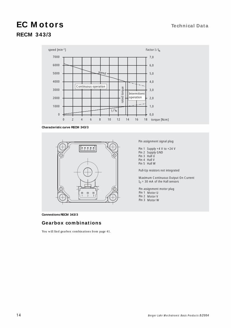
Characteristic curve RECM 343/3
Connections RECM 343/3
Gearbox combinations
You will find gearbox combinations from page 41.
0
1000
2000
3000
4000
5000
6000
7000
torque [Ncm]ra
ted
torq
ue
I / IN
speed
speed [min-1] Factor I / IN
0 2 4 6 8 10 12 14 16 18
0,0
1,0
2,0
3,0
4,0
5,0
6,0
7,0
Continuous operation
Intermittent operation
321
Pin assignment signal plug
Pin 1Pin 2Pin 3Pin 4Pin 5
Supply +4 V to +24 VSupply GNDHall UHall VHall W
Pin assignment motor plugPin 1Pin 2Pin 3
Motor UMotor VMotor W
Pull-Up resistors not integrated
Maximum Continuous Output On CurrentI = 30 mA of the Hall sensorsO

Technical Data EC MotorsRECM 343/4
Berger Lahr Mechatronic Basis Products 8/2004 15
Scale drawing of the RECM 343/4
Technical Data
Rated Voltage 24 V 48 V
Number of pole pairs 4 4
Rated power 59.9 W 59.9 W
Rated torque 13 Ncm 13 Ncm
Rated speed 4400 rpm 4400 rpm
Rated current 3.3 A 1.65 A
No load speed (at operating temperature)
6800 rpm 6800 rpm
No load current 0.22 A 0.11 A
Starting torque 40 Ncm 40 Ncm
Torque constant 3.9 Ncm / A 7.9 Ncm / A
Voltage stabilizer 2.6 mV / rpm 5.2 mV / rpm
Terminal resistance between two phases at 25C
0.83 3.32
Terminal inductance 0.65 mH 2.6 mH
Rotor moment of inertia 62 gcm2 62 gcm2
Thermal resistance between winding and housing
0.75 K / W 0.75 K / W
Max. permitted ambient temperature 40 C 40 C
Max. permitted radial stress Fq 50 N 50 N
Max. permitted axial stress Fa 20 N 20 N
Mass 0.35 kg 0.35 kg
Protection grade IP 41 to DIN EN 60529 IP 54 on request
IP 41IP 54 on request
Insulation class B to DIN EN 60034-1 B
4x Core hole for self-threading screws M4acc. DIN 7500 max. screw depth 6
4x ø 4,2
35
42
80˚
3x
20˚
ø 34
Pin strip SAMTECFWJ-03-01-T-S
Plug connectorJST B5B-PH-K-S
ø 25
h9
ø 6
js5
60,4 ± 1
20
2,5 ± 0,1
13,4
EC Motors Technical Data
RECM 343/4
16 Berger Lahr Mechatronic Basis Products 8/2004
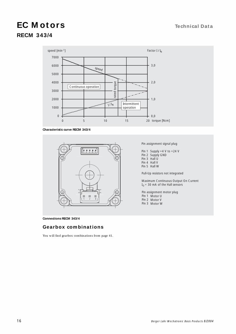
Characteristic curve RECM 343/4
Connections RECM 343/4
Gearbox combinations
You will find gearbox combinations from page 41.
0
1000
2000
3000
4000
5000
6000
7000
torque [Ncm]
I / IN
speed
rate
d to
rque
speed [min-1] Factor I / IN
0 5 10 15 20
0,0
1,0
2,0
3,0
Continuous operation
Intermittent operation
321
Pin assignment signal plug
Pin 1Pin 2Pin 3Pin 4Pin 5
Supply +4 V to +24 VSupply GNDHall UHall VHall W
Pin assignment motor plugPin 1Pin 2Pin 3
Motor UMotor VMotor W
Pull-Up resistors not integrated
Maximum Continuous Output On CurrentI = 30 mA of the Hall sensorsO

Technical Data EC MotorsRECM 345/3
Berger Lahr Mechatronic Basis Products 8/2004 17
Scale drawing of the RECM 345/3
Technical Data
Rated voltage 24 V 48 V
Number of pole pairs 3 3
Rated power 103.7 W 103.7 W
Rated torque 22 Ncm 22 Ncm
Rated speed 4500 rpm 4500 rpm
Rated current 4.82 A 2.41 A
No load speed (at operating temperature)
6250 rpm 6250 rpm
No load current 0.44 A 0.22 A
Starting torque 60 Ncm 60 Ncm
Torque constant 4.56 Ncm / A 9.13 Ncm / A
Voltage stabilizer 2.8 mV / rpm 5.8 mV / rpm
Terminal resistance between two phases at 25C
0.46 2.2
Terminal inductance 0.43 mH 1.85 mH
Rotor moment of inertia 123 gcm2 123 gcm2
Thermal resistance between winding and housing
0.46 K / W 0.46 K / W
Max. permitted ambient temperature 40 C 40 C
Max. permitted radial stress Fq 50 N 50 N
Max. permitted axial stress Fa 20 N 20 N
Mass 0.5 kg 0.5 kg
Protection grade IP 41 to DIN EN 60529 IP 54 on request
IP 41IP 54 on request
Insulation class B to DIN EN 60034-1 B
4x core hole for self-threading screws M4acc. DIN 7500 max. screw depth 6
4x ø 4,2
42
35
80˚
4x
20˚
ø 34
Pin strip SAMTECFWJ-03-01-T-S
Plug connectorJST B5B-PH-K-S85,1 ± 1
20 13,4
2,5 ± 0,1
ø 25
h9
ø 6
js5
EC Motors Technical Data
RECM 345/3
18 Berger Lahr Mechatronic Basis Products 8/2004
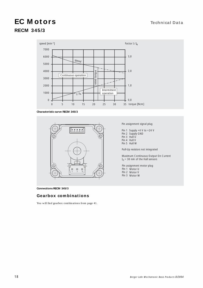
Characteristic curve RECM 345/3
Connections RECM 345/3
Gearbox combinations
You will find gearbox combinations from page 41.
0
1000
2000
3000
4000
5000
6000
7000
rate
d to
rque
torque [Ncm]
I / IN
speed
speed [min-1] Factor I / IN
0 5 10 15 20 25 30 35
0,0
1,0
2,0
3,0
Continuous operation
Intermittent operation
321
Pin assignment signal plug
Pin 1Pin 2Pin 3Pin 4Pin 5
Supply +4 V to +24 VSupply GNDHall UHall VHall W
Pin assignment motor plugPin 1Pin 2Pin 3
Motor UMotor VMotor W
Pull-Up resistors not integrated
Maximum Continuous Output On CurrentI = 30 mA of the Hall sensorsO
Technical Data EC MotorsRECM 345/4
Berger Lahr Mechatronic Basis Products 8/2004 19
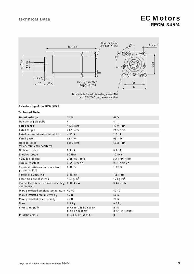
Scale drawing of the RECM 345/4
Technical Data
Rated voltage 24 V 48 V
Number of pole pairs 4 4
Rated speed 4225 rpm 4225 rpm
Rated torque 21.5 Ncm 21.5 Ncm
Rated current at motor terminals 4.62 A 2.31 A
Rated power 95.1 W 95.1 W
No load speed (at operating temperature)
6350 rpm 6350 rpm
No load current 0.41 A 0.21 A
Starting torque 80 Ncm 80 Ncm
Voltage stabilizer 2.85 mV / rpm 5.44 mV / rpm
Torque constant 4.65 Ncm / A 9.31 Ncm / A
Terminal resistance between two phases at 25C
0.48 1.92
Terminal inductance 0.38 mH 1.38 mH
Rotor moment of inertia 123 gcm2 123 gcm2
Thermal resistance between winding and housing
0.46 K / W 0.46 K / W
Max. permitted ambient temperature 40 C 40 C
Max. permitted radial stress Fq 50 N 50 N
Max. permitted axial stress Fa 20 N 20 N
Mass 0.5 kg 0.5 kg
Protection grade IP 41 to DIN EN 60529 IP 54 on request
IP 41IP 54 on request
Insulation class B to DIN EN 60034-1 B
4x core hole for self-threading screws M4acc. DIN 7500 max. screw depth 6
4x ø 4,2
42
35
80˚
4x
20˚
ø 34
Pin strip SAMTECFWJ-03-01-T-S
Plug connectorJST B5B-PH-K-S85,1 ± 1
20 13,4
2,5 ± 0,1
ø 25
h9
ø 6
js5
EC Motors Technical Data
RECM 345/4
20 Berger Lahr Mechatronic Basis Products 8/2004
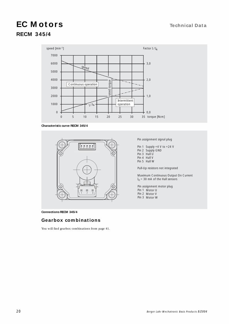
Characteristic curve RECM 345/4
Connections RECM 345/4
Gearbox combinations
You will find gearbox combinations from page 41.
0
1000
2000
3000
4000
5000
6000
7000
rate
d to
rque
torque [Ncm]
I / IN
speed
speed [min-1] Factor I / IN
0 5 10 15 20 25 30 35
0,0
1,0
2,0
3,0
Continuous operation
Intermittent operation
321
Pin assignment signal plug
Pin 1Pin 2Pin 3Pin 4Pin 5
Supply +4 V to +24 VSupply GNDHall UHall VHall W
Pin assignment motor plugPin 1Pin 2Pin 3
Motor UMotor VMotor W
Pull-Up resistors not integrated
Maximum Continuous Output On CurrentI = 30 mA of the Hall sensorsO
Technical Data EC MotorsRECM 372/2
Berger Lahr Mechatronic Basis Products 8/2004 21
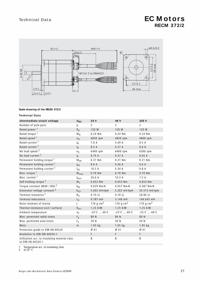
Scale drawing of the RECM 372/2
Technical Data
Intermediate circuit voltage UDC 24 V 48 V 325 V
Number of pole pairs p 2 2 2
Rated power 1
1 Temperature acc. to insulating class
PN 120 W 120 W 120 W
Rated torque 1 MN 0.24 Nm 0.24 Nm 0.24 Nm
Rated speed 1 nN 4850 rpm 4850 rpm 4800 rpm
Rated current 1 IN 7.0 A 3.49 A 0.5 A
Rated current 1 îN 8.5 A 4.27 A 0.6 A
No load speed 2
2 at 25 C
n0 6400 rpm 6400 rpm 6300 rpm
No load current 2 I0 0.74 A 0.37 A 0.05 A
Permanent holding torque 1 Md0 0.31 Nm 0.31 Nm 0.31 Nm
Permanent holding current 1 Id0 8.6 A 4.36 A 0.6 A
Permanent holding current 1 îd0 10.5 A 5.34 A 0.8 A
Max. torque 1 Mmax 0.70 Nm 0.70 Nm 0.70 Nm
Max. current 1 Imax 20.6 A 10.3 A 1.5 A
Self-holding torque 2 MS 0.053 Nm 0.053 Nm 0.053 Nm
Torque constant (Md0 / îd0) 2 kM 0.029 Nm/A 0.057 Nm/A 0.387 Nm/A
Generator voltage constant 2 kEtt 2.602 mV/rpm 5.203 mV/rpm 35.515 mV/rpm
Terminal resistance 2 Rtt 0.19 0.70 28.86
Terminal inductance Ltt 0.787 mH 3.148 mH 146.645 mH
Rotor moment of inertia J 170 g cm2 170 g cm2 170 g cm2
Thermal resistance (coil / surface) Rth1 1.25 K/W 1.25 K/W 1.25 K/W
Ambient temperature F -25C ... 40C -25C ... 40C -25C ... 40C
Max. permitted radial stress Fq 80 N 80 N 80 N
Max. permitted axial stress Fa 30 N 30 N 30 N
Mass m 1.05 kg 1.05 kg 1.05 kg
Protection grade to DIN EN 60529 IP 41 IP 41 IP 41
Insulation to DIN EIN 60034-1 F F F
Utilization acc. to insulating material class to DIN EN 60334-1
B B B
M12x1.5 to EN60423
14.5±1
6±0.2
82±12
2+0.5
400±15
25±
ø40
h8
R7
66 max
52±0.2
±0.
2
ø4.3±0.2
66 m
ax

EC Motors Technical Data
RECM 372/2
22 Berger Lahr Mechatronic Basis Products 8/2004
Characteristic curve RECM 372/2
Connections RECM 372/2
Gearbox combinations
You will find gearbox combinations from page 41.
0 10 20 30 40 500
1000
2000
3000
4000
5000
6000
7000
8000
9000
0,0
0,5
1,0
1,5
2,0
2,5
3,0
3,5
4,0
4,5
rate
d to
rque
torque [Ncm]
Intermittentoperation
Continuous operation
I / IN
speed
speed [min-1] Factor I / IN
Motor U Orange (OR)Motor V Black (BK)Motor W White (WH)PE Earth Yellow/Green (GN/GY)
Supply Vs 4V bis 24V Red (RD)Supply Gnd Blue (BU)Hall U Orange (OR)Hall V Black (BK)Hall W White (WH)
400±15
300±15
15±1
M12x1.5 to EN60423
14.5±1
Pull-up resistors not integrated
Maximum Continuous Output On CurrentI = 30 mA of the Hall sensorsO

Technical Data EC MotorsRECM 372/4
Berger Lahr Mechatronic Basis Products 8/2004 23
Scale drawing of the RECM 372/4
Technical Data
Intermediate circuit voltage UDC 24 V 48 V 325 V
Number of pole pairs p 4 4 4
Rated power 1
1 Temperature acc. to insulating class
PN 130 W 130 W 120 W
Rated torque 1 MN 0.28 Nm 0.28 Nm 0.28 Nm
Rated speed 1 nN 4350 rpm 4350 rpm 4300 rpm
Rated current 1 IN 8.1 A 4.03 A 0.6 A
Rated current 1 îN 9.9 A 4.93 A 0.7 A
No load speed 2
2 at 25 C
n0 6500 rpm 6500 rpm 6450 rpm
No load current 2 I0 0.63 A 0.31 A 0.05 A
Permanent holding torque 1 Md0 0.33 Nm 0.33 Nm 0.33 Nm
Permanent holding current 1 Id0 9.1 A 4.70 A 0.7 A
Permanent holding current 1 îd0 11.2 A 5.76 A 0.9 A
Max. torque 1 Mmax 0.7 Nm 0.7 Nm 0.7 Nm
Max. current 1 Imax 20.7 A 10.3 A 1.5 A
Self-holding torque 2 MS 0.015 Nm 0.015 Nm 0.015 Nm
Torque constant (Md0 / îd0) 2 kM 0.030 Nm/A 0.057 Nm/A 0.386 Nm/A
Generator voltage constant 2 kEtt 2.583 mV/rpm 5.166 mV/rpm 35.091 mV/rpm
Terminal resistance 2 Rtt 0.17 0.54 21.38
Terminal inductance Ltt 0.619 mH 2.477 mH 114.269 mH
Rotor moment of inertia J 170 g cm2 170 g cm2 170 g cm2
Thermal resistance (coil / surface) Rth1 1.25 K/W 1.25 K/W 1.25 K/W
Ambient temperature F -25 °C ... 40 C -25 °C ... 40 C -25 °C ... 40 C
Max. permitted radial stress Fq 80 N 80 N 80 N
Max. permitted axial stress Fa 30 N 30 N 30 N
Mass m 1.05 kg 1.05 kg 1.05 kg
Protection grade to DIN EN 60529 IP 41 IP 41 IP 41
Insulation to DIN EIN 60034-1 F F F
Utilization acc. to insulating material class to DIN EN 60334-1
B B B
M12x1.5 to EN60423
14.5±1
6±0.2
82±12
2+0.5
400±15
25±
ø40
h8
R7
66 max
52±0.2
±0.
2
ø4.3±0.2
66 m
ax

EC Motors Technical Data
RECM 372/4
24 Berger Lahr Mechatronic Basis Products 8/2004
Characteristic curve RECM 372/4
Connections RECM 372/4
Gearbox combinations
You will find gearbox combinations from page 41.
0 10 20 30 40 500
1000
2000
3000
4000
5000
6000
7000
0,0
0,5
1,0
1,5
2,0
2,5
3,0
3,5
rate
d to
rque
torque [Ncm]
Continuous operation
I / IN
speed
speed [min-1] Factor I / IN
Intermittentoperation
Motor U Orange (OR)Motor V Black (BK)Motor W White (WH)PE Earth Yellow/Green (GN/GY)
Supply Vs 4V bis 24V Red (RD)Supply Gnd Blue (BU)Hall U Orange (OR)Hall V Black (BK)Hall W White (WH)
400±15
300±15
15±1
M12x1.5 to EN60423
14.5±1
Pull-up resistors not integrated
Maximum Continuous Output On CurrentI = 30 mA of the Hall sensorsO

Technical Data EC MotorsRECM 374/2
Berger Lahr Mechatronic Basis Products 8/2004 25
Scale drawing of the RECM 374/2
Technical Data
Intermediate circuit voltage UDC 24 V 48 V 325 V
Number of pole pairs p 2 2 2
Rated power 1
1 Temperature acc. to insulating class
PN 190 W 190 W 180 W
Rated torque 1 MN 0.38 Nm 0.38 Nm 0.38 Nm
Rated speed 1 nN 4750 rpm 4750 rpm 4500 rpm
Rated current 1 IN 9.7 A 4.84 A 0.6 A
Rated current 1 îN 11.9 A 5.93 A 0.8 A
No load speed 2
2 at 25 C
n0 5800 rpm 5800 rpm 5450 rpm
No load current 2 I0 1.20 A 0.60 A 0.08 A
Permanent holding torque 1 Md0 0.53 Nm 0.53 Nm 0.53 Nm
Permanent holding current 1 Id0 13.1 A 6.87 A 1.0 A
Permanent holding current 1 îd0 16.1 A 8.41 A 1.2 A
Max. torque 1 Mmax 1.40 Nm 1.40 Nm 1.40 Nm
Max. current 1 Imax 37.1 A 18.5 A 2.6 A
Self-holding torque 2 MS 0.106 Nm 0.106 Nm 0.106 Nm
Torque constant (Md0 / îd0) 2 kM 0.033 Nm/A 0.064 Nm/A 0.446 Nm/A
Generator voltage constant 2 kEtt 2.891 mV/rpm 5.781 mV/rpm 41.296 mV/rpm
Terminal resistance 2 Rtt 0.12 0.39 15.55
Terminal inductance Ltt 0.389 mH 1.557 mH 79.430 mH
Rotor moment of inertia J 340 g cm2 340 g cm2 340 g cm2
Thermal resistance (coil / surface) Rth1 0.63 K/W 0.63 K/W 0.63 K/W
Ambient temperature F -25C ... 40C -25C ... 40C -25C ... 40C
Max. permitted radial stress Fq 80 N 80 N 80 N
Max. permitted axial stress Fa 30 N 30 N 30 N
Mass m 1.4 kg 1.4 kg 1.4 kg
Protection grade to DIN EN 60529 IP 41 IP 41 IP 41
Insulation to DIN EIN 60034-1 F F F
Utilization acc. to insulating material class to EN 60334-1
B B B
100±1 400±15±15
M12x1.5 to EN60423
6±0.2
2+0.514.5±1
25±
ø40
h8
R7
66 max
52±0.2
±0.
2
ø4.3±0.2
66 m
ax
EC Motors Technical Data
RECM 374/2
26 Berger Lahr Mechatronic Basis Products 8/2004
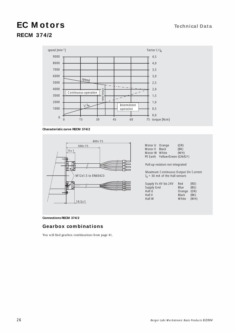
Characteristic curve RECM 374/2
Connections RECM 374/2
Gearbox combinations
You will find gearbox combinations from page 41.
0 15 30 45 60 750
1000
2000
3000
4000
5000
6000
7000
8000
9000
0,0
0,5
1,0
1,5
2,0
2,5
3,0
3,5
4,0
4,5
torque [Ncm]
Intermittent operation
Continuous operation
I / IN
speed
speed [min-1] Factor I / IN
rate
d t
orq
ue
Motor U Orange (OR)Motor V Black (BK)Motor W White (WH)PE Earth Yellow/Green (GN/GY)
Supply Vs 4V bis 24V Red (RD)Supply Gnd Blue (BU)Hall U Orange (OR)Hall V Black (BK)Hall W White (WH)
400±15
300±15
15±1
M12x1.5 to EN60423
14.5±1
Pull-up resistors not integrated
Maximum Continuous Output On CurrentI = 30 mA of the Hall sensorsO

Technical Data EC MotorsRECM 374/4
Berger Lahr Mechatronic Basis Products 8/2004 27
Scale drawing of the RECM 374/4
Technical Data
Intermediate circuit voltage UDC 24 V 48 V 325 V
Number of pole pairs p 4 4 4
Rated power 1
1 Temperature acc. to insulating class
PN 160 W 200 W 200 W
Rated torque 1 MN 0.37 Nm 0.44 Nm 0.44 Nm
Rated speed 1 nN 4250 rpm 4350 rpm 4400 rpm
Rated current 1 IN 9.2 A 5.54 A 0.8 A
Rated current 1 îN 11.3 A 6.78 A 1.0 A
No load speed 2
2 at 25 C
n0 5800 rpm 5800 rpm 5850 rpm
No load current 2 I0 0.63 A 0.46 A 0.07 A
Permanent holding torque 1 Md0 0.58 Nm 0.58 Nm 0.58 Nm
Permanent holding current 1 Id0 11.9 A 7.29 A 1.2 A
Permanent holding current 1 îd0 14.5 A 8.92 A 1.4 A
Max. torque 1 Mmax 1.40 Nm 1.40 Nm 1.40 Nm
Max. current 1 Imax 36.5 A 18.3 A 2.7 A
Self-holding torque 2 MS 0.030 Nm 0.030 Nm 0.030 Nm
Torque constant (Md0 / îd0) 2 kM 0.040 Nm/A 0.065 Nm/A 0.406 Nm/A
Generator voltage constant 2 kEtt 2.924 mV/rpm 5.848 mV/rpm 38.990 mV/rpm
Terminal resistance 2 Rtt 0.11 0.28 9.85
Terminal inductance Ltt 0.318 mH 1.272 mH 56.514 mH
Rotor moment of inertia J 340 g cm2 340 g cm2 340 g cm2
Thermal resistance (coil / surface) Rth1 0.63 K/W 0.63 K/W 0.63 K/W
Ambient temperature F -25C ... 40C -25C ... 40C -25C ... 40C
Max. permitted radial stress Fq 80 N 80 N 80 N
Max. permitted axial stress Fa 30 N 30 N 30 N
Mass m 1.4 kg 1.4 kg 1.4 kg
Protection grade to DIN EN 60529 IP 41 IP 41 IP 41
Insulation to DIN EIN 60034-1 F F F
Utilization acc. to insulating material class to DIN EN 60334-1
B B B
100±1 400±15±15
M12x1.5 to EN60423
6±0.2
2+0.514.5±1
25±
ø40
h8
R7
66 max
52±0.2
±0.
2
ø4.3±0.2
66 m
ax
EC Motors Technical Data
RECM 374/4
28 Berger Lahr Mechatronic Basis Products 8/2004
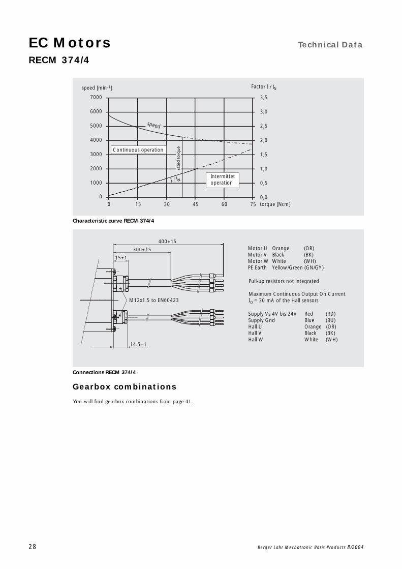
Characteristic curve RECM 374/4
Connections RECM 374/4
Gearbox combinations
You will find gearbox combinations from page 41.
0 15 30 45 60 750
1000
2000
3000
4000
5000
6000
7000
0,0
0,5
1,0
1,5
2,0
2,5
3,0
3,5
torque [Ncm]
speed [min-1]
Intermittet operation
Continuous operation
I / IN
Factor I / IN
speed
rate
d t
orq
ue
Motor U Orange (OR)Motor V Black (BK)Motor W White (WH)PE Earth Yellow/Green (GN/GY)
Supply Vs 4V bis 24V Red (RD)Supply Gnd Blue (BU)Hall U Orange (OR)Hall V Black (BK)Hall W White (WH)
400±15
300±15
15±1
M12x1.5 to EN60423
14.5±1
Pull-up resistors not integrated
Maximum Continuous Output On CurrentI = 30 mA of the Hall sensorsO

Technical Data EC MotorsRECM 375/2
Berger Lahr Mechatronic Basis Products 8/2004 29
Scale drawing of the RECM 375/2
Technical Data
Intermediate circuit voltage UDC 48 V 60 V 325 V
Number of pole pairs p 2 2 2
Rated power 1
1 Temperature acc. to insulating class
PN 250 W 260 W 250 W
Rated torque 1 MN 0.48 Nm 0.48 Nm 0.48 Nm
Rated speed 1 nN 5000 rpm 5100 rpm 5000 rpm
Rated current 1 IN 6.37 A 5.4 A 0.9 A
Rated current 1 îN 7.8 A 6.6 A 1.2 A
No load speed 2
2 at 25 C
n0 5900 rpm 6050 rpm 5900 rpm
No load current 2 I0 0.91 A 0.76 A 0.13 A
Permanent holding torque 1 Md0 0.81 Nm 0.81 Nm 0.81 Nm
Permanent holding current 1 Id0 10.51 A 9.0 A 1.7 A
Permanent holding current 1 îd0 12.87 A 11.0 A 2.1 A
Max. torque 1 Mmax 2.10 Nm 2.10 Nm 2.10 Nm
Max. current 1 Imax 28.2 A 23.2 A 4.2 A
Self-holding torque 2 MS 0.158 Nm 0.158 Nm 0.158 Nm
Torque constant (Md0 / îd0) 2 kM 0.063 Nm/A 0.073 Nm/A 0.382 Nm/A
Generator voltage constant 2 kEtt 5.699 mV/rpm 6.938 mV/rpm 38.405 mV/rpm
Terminal resistance 2 Rtt 0.22 0.31 7.33
Terminal inductance Ltt 0.925 mH 1.371 mH 42.011 mH
Rotor moment of inertia J 510 g cm2 510 g cm2 510 g cm2
Thermal resistance (coil / surface) Rth1 0.42 K/W 0.42 K/W 0.42 K/W
Ambient temperature F -25C ... 40C -25C ... 40C -25C ... 40C
Max. permitted radial stress Fq 80 N 80 N 80 N
Max. permitted axial stress Fa 30 N 30 N 30 N
Mass m 1.7 kg 1.7 kg 1.7 kg
Protection grade to DIN EN 60529 IP 41 IP 41 IP 41
Insulation to DIN EIN 60034-1 F F F
Utilization acc. to insulating material class to DIN EN 60334-1
B B B
M12x1,5 to EN60234
118±1.2±15
400±15
±1
25±
2+0,514,5±1
6±0,2,
ø40h
8
R7
66 max
52±0.2
±0.
2
ø4.3±0.2
66 m
ax
EC Motors Technical Data
RECM 375/2
30 Berger Lahr Mechatronic Basis Products 8/2004
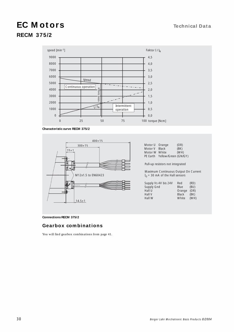
Characteristic curve RECM 375/2
Connections RECM 375/2
Gearbox combinations
You will find gearbox combinations from page 41.
0 25 50 75 100
0
1000
2000
3000
4000
5000
6000
7000
8000
9000
0,0
0,5
1,0
1,5
2,0
2,5
3,0
3,5
4,0
4,5
rate
d to
rque
torque [Ncm]
Intermittentoperation
Continuous operation
I / IN
speed
speed [min-1] Faktor I / IN
Motor U Orange (OR)Motor V Black (BK)Motor W White (WH)PE Earth Yellow/Green (GN/GY)
Supply Vs 4V bis 24V Red (RD)Supply Gnd Blue (BU)Hall U Orange (OR)Hall V Black (BK)Hall W White (WH)
400±15
300±15
15±1
M12x1.5 to EN60423
14.5±1
Pull-up resistors not integrated
Maximum Continuous Output On CurrentI = 30 mA of the Hall sensorsO
Technical Data EC MotorsRECM 375/4
Berger Lahr Mechatronic Basis Products 8/2004 31
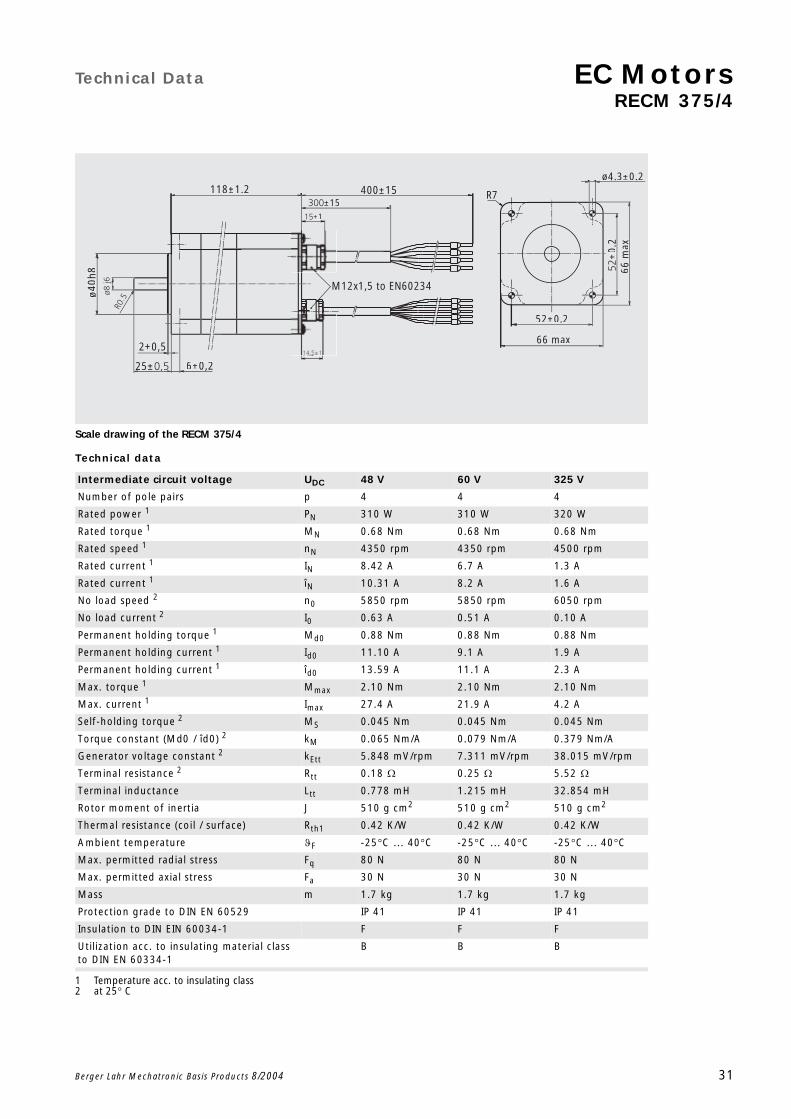
Scale drawing of the RECM 375/4
Technical data
Intermediate circuit voltage UDC 48 V 60 V 325 V
Number of pole pairs p 4 4 4
Rated power 1
1 Temperature acc. to insulating class
PN 310 W 310 W 320 W
Rated torque 1 MN 0.68 Nm 0.68 Nm 0.68 Nm
Rated speed 1 nN 4350 rpm 4350 rpm 4500 rpm
Rated current 1 IN 8.42 A 6.7 A 1.3 A
Rated current 1 îN 10.31 A 8.2 A 1.6 A
No load speed 2
2 at 25 C
n0 5850 rpm 5850 rpm 6050 rpm
No load current 2 I0 0.63 A 0.51 A 0.10 A
Permanent holding torque 1 Md0 0.88 Nm 0.88 Nm 0.88 Nm
Permanent holding current 1 Id0 11.10 A 9.1 A 1.9 A
Permanent holding current 1 îd0 13.59 A 11.1 A 2.3 A
Max. torque 1 Mmax 2.10 Nm 2.10 Nm 2.10 Nm
Max. current 1 Imax 27.4 A 21.9 A 4.2 A
Self-holding torque 2 MS 0.045 Nm 0.045 Nm 0.045 Nm
Torque constant (Md0 / îd0) 2 kM 0.065 Nm/A 0.079 Nm/A 0.379 Nm/A
Generator voltage constant 2 kEtt 5.848 mV/rpm 7.311 mV/rpm 38.015 mV/rpm
Terminal resistance 2 Rtt 0.18 0.25 5.52
Terminal inductance Ltt 0.778 mH 1.215 mH 32.854 mH
Rotor moment of inertia J 510 g cm2 510 g cm2 510 g cm2
Thermal resistance (coil / surface) Rth1 0.42 K/W 0.42 K/W 0.42 K/W
Ambient temperature F -25C ... 40C -25C ... 40C -25C ... 40C
Max. permitted radial stress Fq 80 N 80 N 80 N
Max. permitted axial stress Fa 30 N 30 N 30 N
Mass m 1.7 kg 1.7 kg 1.7 kg
Protection grade to DIN EN 60529 IP 41 IP 41 IP 41
Insulation to DIN EIN 60034-1 F F F
Utilization acc. to insulating material class to DIN EN 60334-1
B B B
M12x1,5 to EN60234
118±1.2±15
400±15
±1
25±
2+0,514,5±1
6±0,2,
ø40h
8
R7
66 max
52±0.2
±0.
2
ø4.3±0.2
66 m
ax
EC Motors Technical Data
RECM 375/4
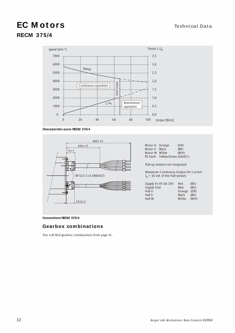
32 Berger Lahr Mechatronic Basis Products 8/2004
Characteristic curve RECM 375/4
Connections RECM 375/4
Gearbox combinations
You will find gearbox combinations from page 41.
torque [Ncm]
I / IN
speed
speed [min-1] Factor I / IN
0 20 40 60 80 100
0
1000
2000
3000
4000
5000
6000
7000
0,0
0,5
1,0
1,5
2,0
2,5
3,0
3,5
Continuous operation
Intermittent operation
rate
d to
rque
Motor U Orange (OR)Motor V Black (BK)Motor W White (WH)PE Earth Yellow/Green (GN/GY)
Supply Vs 4V bis 24V Red (RD)Supply Gnd Blue (BU)Hall U Orange (OR)Hall V Black (BK)Hall W White (WH)
400±15
300±15
15±1
M12x1.5 to EN60423
14.5±1
Pull-up resistors not integrated
Maximum Continuous Output On CurrentI = 30 mA of the Hall sensorsO

Technical Data EC MotorsRECM 377/2
Berger Lahr Mechatronic Basis Products 8/2004 33
Scale drawing of the RECM 377/2
Technical Data
Intermediate circuit voltage UDC 48 V 60 V 325 V
Number of pole pairs p 2 2 2
Rated power 1
1 Temperature acc. to insulating class
PN 350 W 370 W 360 W
Rated torque 1 MN 0.67 Nm 0.67 Nm 0.67 Nm
Rated speed 1 nN 5000 rpm 5300 rpm 5200 rpm
Rated current 1 IN 8.91 A 8.0 A 1.4 A
Rated current 1 îN 10.92 A 9.8 A 1.8 A
No load speed 2
2 at 25 C
n0 6000 rpm 6350 rpm 6250 rpm
No load current 2 I0 1.24 A 1.12 A 0.20 A
Permanent holding torque 1 Md0 1.08 Nm 1.08 Nm 1.08 Nm
Permanent holding current 1 Id0 14.33 A 13.0 A 2.5 A
Permanent holding current 1 î d0 17.55 A 15.9 A 3.1 A
Max. torque 1 Mmax 2.80 Nm 2.80 Nm 2.80 Nm
Max. current 1 Imax 38.2 A 32.4 A 5.9 A
Self-holding torque 2 M5 0.211 Nm 0.211 Nm 0.211 Nm
Torque constant (Md0 / îd0) 2 kM 0.062 Nm/A 0.068 Nm/A 0.352 Nm/A
Generator voltage constant 2 kEtt 5.616 mV/rpm 6.607 mV/rpm 36.341 mV/rpm
Terminal resistance 2 Rtt 0.16 0.21 5.08
Terminal inductance Ltt 0.643 mH 0.891 mH 26.940 mH
Rotor moment of inertia J 680 g cm2 680 g cm2 680 g cm2
Thermal resistance (coil / surface) Rth1 0.31 K/W 0.31 K/W 0.31 K/W
Ambient temperature F -25C ... 40C -25C ... 40C -25C... 40C
Max. permitted radial stress Fq 80 N 80 N 80 N
Max. permitted axial stress Fa 30 N 30 N 30 N
Mass m 2.05 kg 2.05 kg 2.05 kg
Protection grade to DIN EN 60529 IP 41 IP 41 IP 41
Insulation to DIN EIN 60034-1 F F F
Utilization acc. to insulating material class to DIN EN 60334-1
B B B
136±1.2 400±15±15
M12x1,5 to EN60423
±1
25± 6±0.2
ø40h
8
R7
66 max
52±0.2
±0.
2
ø4.3±0.2
66 m
ax

EC Motors Technical Data
RECM 377/2
34 Berger Lahr Mechatronic Basis Products 8/2004
Characteristic curve RECM 377/2
Connections RECM 377/2
Gearbox combinations
You will find gearbox combinations from page 41.
0 25 50 75 100 125
0
1000
2000
3000
4000
5000
6000
7000
8000
9000
0,0
0,5
1,0
1,5
2,0
2,5
3,0
3,5
4,0
4,5
rate
d to
rque
torque [Ncm]
Intermittent operation
Continuous operation
I / IN
speed [min-1] Factor I / IN
speed
Motor U Orange (OR)Motor V Black (BK)Motor W White (WH)PE Earth Yellow/Green (GN/GY)
Supply Vs 4V bis 24V Red (RD)Supply Gnd Blue (BU)Hall U Orange (OR)Hall V Black (BK)Hall W White (WH)
400±15
300±15
15±1
M12x1.5 to EN60423
14.5±1
Pull-up resistors not integrated
Maximum Continuous Output On CurrentI = 30 mA of the Hall sensorsO
Technical Data EC MotorsRECM 377/4
Berger Lahr Mechatronic Basis Products 8/2004 35
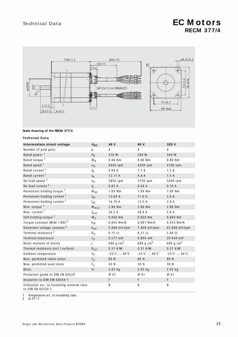
Scale drawing of the RECM 377/4
Technical Data
Intermediate circuit voltage UDC 48 V 60 V 325 V
Number of pole pairs p 4 4 4
Rated power 1
1 Temperature acc. to insulating class
PN 370 W 360 W 340 W
Rated torque 1 MN 0.80 Nm 0.80 Nm 0.80 Nm
Rated speed 1 nN 4450 rpm 4350 rpm 4100 rpm
Rated current 1 IN 9.94 A 7.7 A 1.3 A
Rated current 1 îN 12.17 A 9.4 A 1.5 A
No load speed 2
2 at 25 C
n0 5850 rpm 5750 rpm 5400 rpm
No load current 2 I0 0.83 A 0.64 A 0.10 A
Permanent holding torque 1 Md0 1.09 Nm 1.09 Nm 1.09 Nm
Permanent holding current 1 Id0 13.69 A 11.0 A 2.0 A
Permanent holding current 1 îd0 16.76 A 13.5 A 2.4 A
Max. torque 1 Mmax 2.80 Nm 2.80 Nm 2.80 Nm
Max. current 1 Imax 36.5 A 28.8 A 5.0 A
Self-holding torque 2 MS 0.060 Nm 0.060 Nm 0.060 Nm
Torque constant (Md0 / îd0) 2 kM 0.065 Nm/A 0.081 Nm/A 0.453 Nm/A
Generator voltage constant 2 kEtt 5.848 mV/rpm 7.408 mV/rpm 42.888 mV/rpm
Terminal resistance 2 Rtt 0.15 0.21 5.08
Terminal inductance Ltt 0.577 mH 0.894 mH 29.949 mH
Rotor moment of inertia J 680 g cm2 680 g cm2 680 g cm2
Thermal resistance (coil / surface) Rth1 0.31 K/W 0.31 K/W 0.31 K/W
Ambient temperature F -25C ... 40C -25C ... 40C -25C ... 40C
Max. permitted radial stress Fq 80 N 80 N 80 N
Max. permitted axial stress Fa 30 N 30 N 30 N
Mass m 2.05 kg 2.05 kg 2.05 kg
Protection grade to DIN EN 60529 IP 41 IP 41 IP 41
Insulation to DIN EIN 60034-1 F F F
Utilization acc. to insulating material class to DIN EN 60334-1
B B B
136±1.2 400±15±15
M12x1,5 to EN60423
±1
25± 6±0.2
ø40h
8
R7
66 max
52±0.2
±0.
2
ø4.3±0.2
66 m
ax
EC Motors Technical Data
36 Berger Lahr Mechatronic Basis Products 8/2004
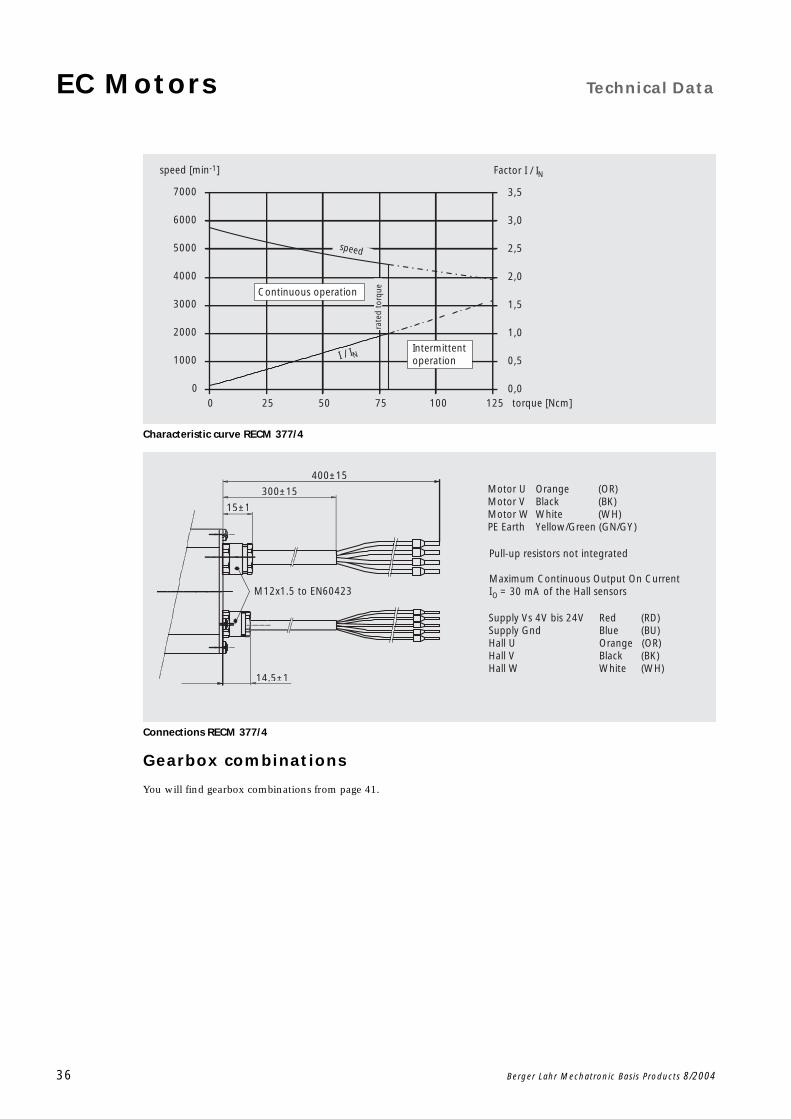
Characteristic curve RECM 377/4
Connections RECM 377/4
Gearbox combinations
You will find gearbox combinations from page 41.
0 25 50 75 100 1250
1000
2000
3000
4000
5000
6000
7000
0,0
0,5
1,0
1,5
2,0
2,5
3,0
3,5
rate
d to
rque
torque [Ncm]
Intermittent operation
Continuous operation
I / IN
Factor I / IN
speed
speed [min-1]
Motor U Orange (OR)Motor V Black (BK)Motor W White (WH)PE Earth Yellow/Green (GN/GY)
Supply Vs 4V bis 24V Red (RD)Supply Gnd Blue (BU)Hall U Orange (OR)Hall V Black (BK)Hall W White (WH)
400±15
300±15
15±1
M12x1.5 to EN60423
14.5±1
Pull-up resistors not integrated
Maximum Continuous Output On CurrentI = 30 mA of the Hall sensorsO
Options EC MotorsExternal drive electronics BL-SCx
Berger Lahr Mechatronic Basis Products 8/2004 37
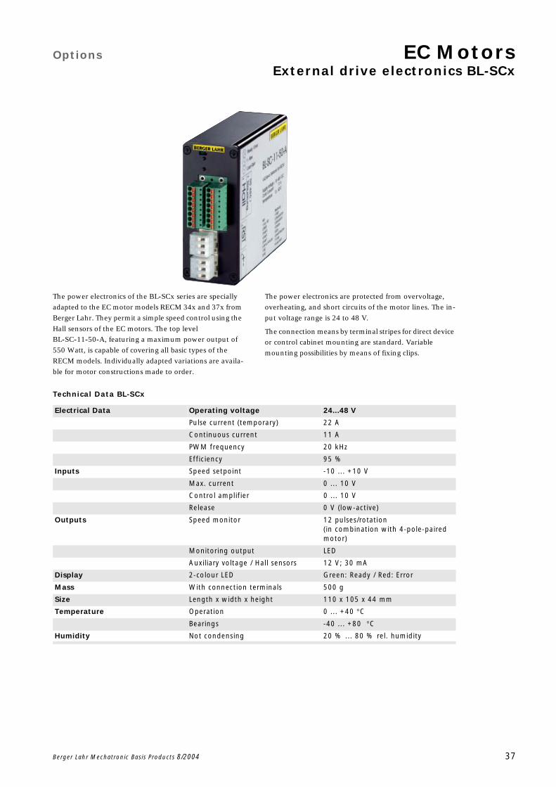
The power electronics of the BL-SCx series are specially
adapted to the EC motor models RECM 34x and 37x from
Berger Lahr. They permit a simple speed control using the
Hall sensors of the EC motors. The top level
BL-SC-11-50-A, featuring a maximum power output of
550 Watt, is capable of covering all basic types of the
RECM models. Individually adapted variations are availa-
ble for motor constructions made to order.
The power electronics are protected from overvoltage,
overheating, and short circuits of the motor lines. The in-
put voltage range is 24 to 48 V.
The connection means by terminal stripes for direct device
or control cabinet mounting are standard. Variable
mounting possibilities by means of fixing clips.
Technical Data BL-SCx
Electrical Data Operating voltage 24...48 V
Pulse current (temporary) 22 A
Continuous current 11 A
PWM frequency 20 kHz
Efficiency 95 %
Inputs Speed setpoint -10 ... +10 V
Max. current 0 ... 10 V
Control amplifier 0 ... 10 V
Release 0 V (low-active)
Outputs Speed monitor 12 pulses/rotation(in combination with 4-pole-paired motor)
Monitoring output LED
Auxiliary voltage / Hall sensors 12 V; 30 mA
Display 2-colour LED Green: Ready / Red: Error
Mass With connection terminals 500 g
Size Length x width x height 110 x 105 x 44 mm
Temperature Operation 0 ... +40 C
Bearings -40 ... +80 C
Humidity Not condensing 20 % ... 80 % rel. humidity
EC Motors
38 Berger Lahr Mechatronic Basis Products 8/2004
Options EC MotorsRECM 372/4 with integrated electronics
Berger Lahr Mechatronic Basis Products 8/2004 39
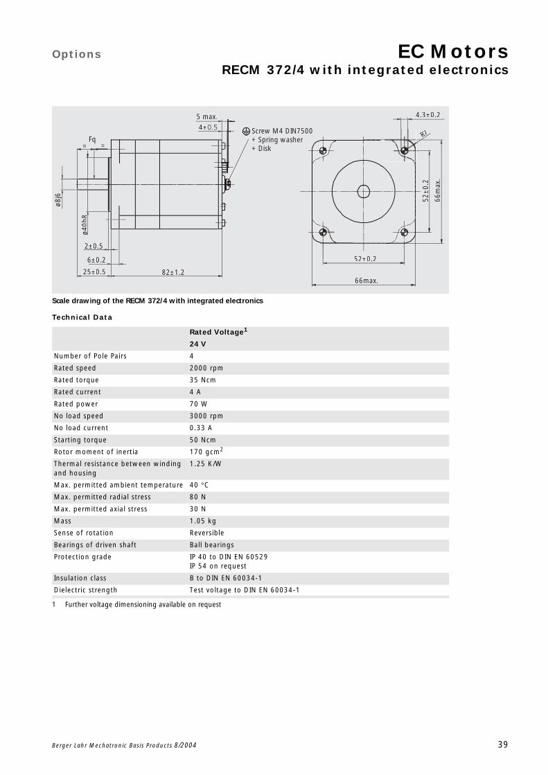
Scale drawing of the RECM 372/4 with integrated electronics
Technical Data
Rated Voltage1
1 Further voltage dimensioning available on request
24 V
Number of Pole Pairs 4
Rated speed 2000 rpm
Rated torque 35 Ncm
Rated current 4 A
Rated power 70 W
No load speed 3000 rpm
No load current 0.33 A
Starting torque 50 Ncm
Rotor moment of inertia 170 gcm2
Thermal resistance between winding and housing
1.25 K/W
Max. permitted ambient temperature 40 C
Max. permitted radial stress 80 N
Max. permitted axial stress 30 N
Mass 1.05 kg
Sense of rotation Reversible
Bearings of driven shaft Ball bearings
Protection grade IP 40 to DIN EN 60529IP 54 on request
Insulation class B to DIN EN 60034-1
Dielectric strength Test voltage to DIN EN 60034-1
66max.
52±0.2
66m
ax.
52±
0.2
R7
4.3±0.25 max.
82±1.225±0.5
6±0.2
2±0.5
ø8j6
ø40h
88
Fq= =
4± Screw M4 DIN7500 + Spring washer+ Disk
EC Motors Options
RECM 372/4 with integrated electronics
40 Berger Lahr Mechatronic Basis Products 8/2004
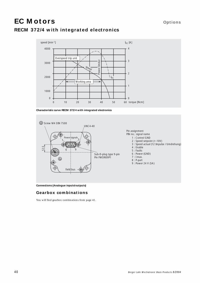
Characteristic curve RECM 372/4 with integrated electronics
Connections (Analogue inputs/outputs)
Gearbox combinations
You will find gearbox combinations from page 41.
0
1000
2000
3000
4000
Pow
er li
mite
rtorque [Ncm]
speed [min-1] IDC [A]
IDC
0 20 30 5010 40 60
speed
0
1
2
3
4
Overspeed trip unit
Working area
Screw M4 DIN 7500UNC4-40
Power signals
field bus
12.5
1
6
5
9
Sub-D-plug type 9-pin Pin FWDR09P1
Pin assignmentPIN no.: signal name
1 : Control GND2 : Speed setpoint (+-10V)3 : Speed actual (12 Impulse / Umdrehung)4 : Enable5 : Faults6 : Power (GND)7 : I max.8 : P-part9 : Power 24 V (5A)
Options EC MotorsOverview geared motors
Berger Lahr Mechatronic Basis Products 8/2004 41
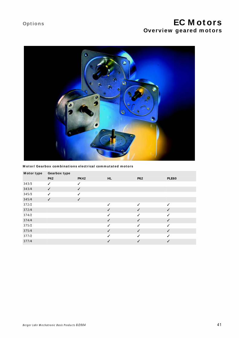
Motor/ Gearbox combinations electrical commutated motors
Motor type Gearbox type
P42 PK42 HL P62 PLE60
343/3
343/4
345/3
345/4
372/2
372/4
374/2
374/4
375/2
375/4
377/2
377/4
EC Motors Options
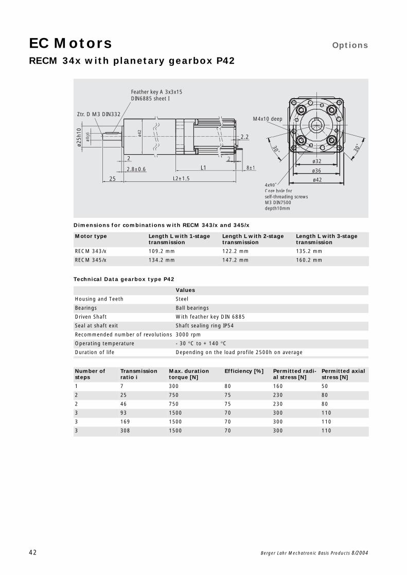
RECM 34x with planetary gearbox P42
42 Berger Lahr Mechatronic Basis Products 8/2004
Dimensions for combinations with RECM 343/x and 345/x
Technical Data gearbox type P42
Motor type Length L with 1-stage transmission
Length L with 2-stage transmission
Length L with 3-stage transmission
RECM 343/x 109.2 mm 122.2 mm 135.2 mm
RECM 345/x 134.2 mm 147.2 mm 160.2 mm
Values
Housing and Teeth Steel
Bearings Ball bearings
Driven Shaft With feather key DIN 6885
Seal at shaft exit Shaft sealing ring IP54
Recommended number of revolutions 3000 rpm
Operating temperature - 30 C to + 140 C
Duration of life Depending on the load profile 2500h on average
Feather key A 3x3x15DIN6885 sheet I
25
2
L1
2.2
M4x10 deep
L2±1.5
ø25h
10ø
ø42
8±12.8±0.6
Ztr. D M3 DIN332
4x90˚Core hole forself-threading screws M3 DIN7500 depth10mm
30˚30˚
ø32
ø36
ø42
Number of steps
Transmission ratio i
Max. duration torque [N]
Efficiency [%] Permitted radi-al stress [N]
Permitted axial stress [N]
1 7 300 80 160 50
2 25 750 75 230 80
2 46 750 75 230 80
3 93 1500 70 300 110
3 169 1500 70 300 110
3 308 1500 70 300 110
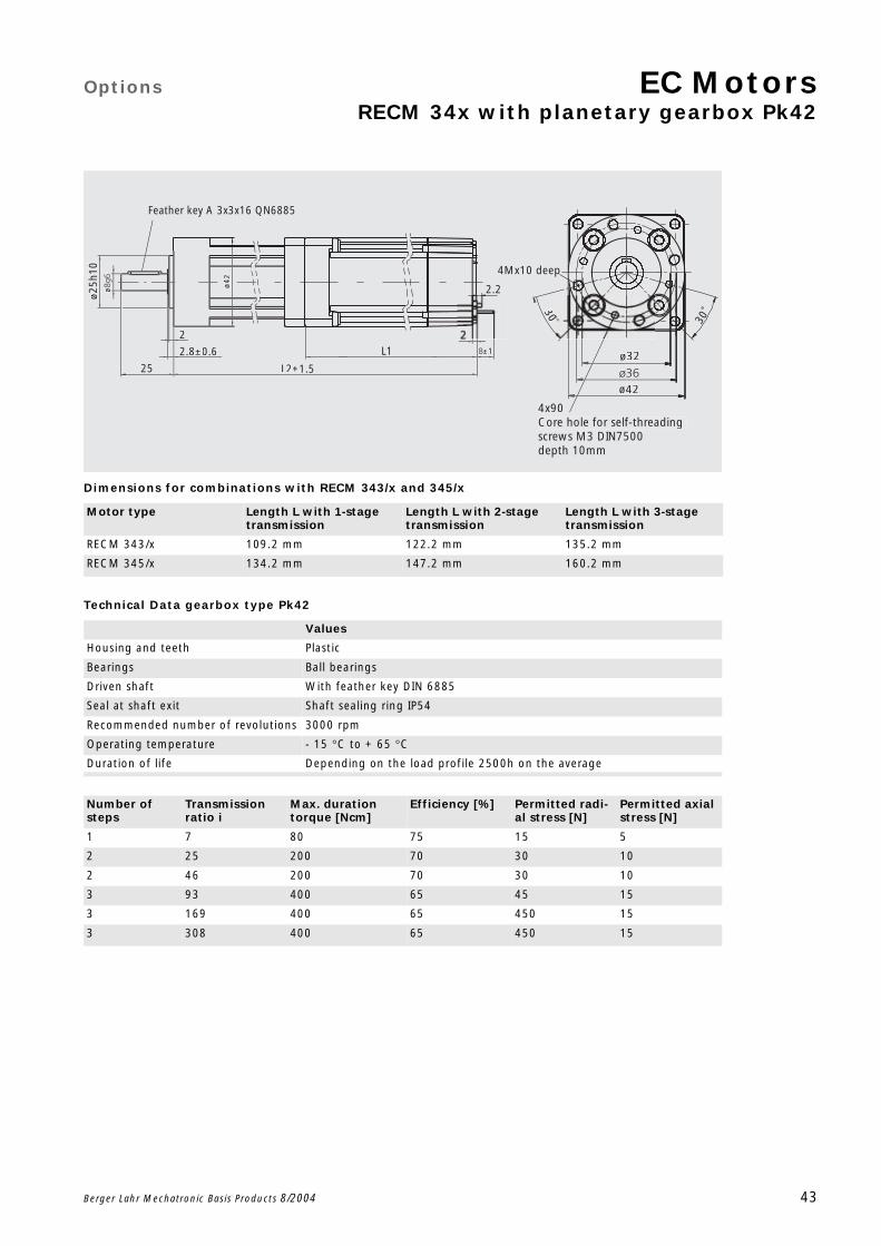
Options EC MotorsRECM 34x with planetary gearbox Pk42
Berger Lahr Mechatronic Basis Products 8/2004 43
Dimensions for combinations with RECM 343/x and 345/x
Technical Data gearbox type Pk42
Motor type Length L with 1-stage transmission
Length L with 2-stage transmission
Length L with 3-stage transmission
RECM 343/x 109.2 mm 122.2 mm 135.2 mm
RECM 345/x 134.2 mm 147.2 mm 160.2 mm
Values
Housing and teeth Plastic
Bearings Ball bearings
Driven shaft With feather key DIN 6885
Seal at shaft exit Shaft sealing ring IP54
Recommended number of revolutions 3000 rpm
Operating temperature - 15 C to + 65 C
Duration of life Depending on the load profile 2500h on the average
2
25
Feather key A 3x3x16 QN6885
2.2
L1
L2±1.5
4Mx10 deep
ø32
ø42
30
30˚
4x90Core hole for self-threading screws M3 DIN7500depth 10mm
ø25h
10ø ø4
2
±12.8±0.6
Number of steps
Transmission ratio i
Max. duration torque [Ncm]
Efficiency [%] Permitted radi-al stress [N]
Permitted axial stress [N]
1 7 80 75 15 5
2 25 200 70 30 10
2 46 200 70 30 10
3 93 400 65 45 15
3 169 400 65 450 15
3 308 400 65 450 15
EC Motors Options
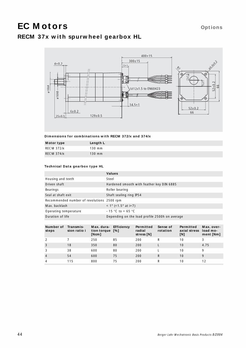
RECM 37x with spurwheel gearbox HL
44 Berger Lahr Mechatronic Basis Products 8/2004
Dimensions for combinations with RECM 372/x and 374/x
Technical Data gearbox type HL
Motor type Length L
RECM 372/x 130 mm
RECM 374/x 130 mm
Values
Housing and teeth Steel
Driven shaft Hardened smooth with feather key DIN 6885
Bearings Roller bearing
Seal at shaft exit Shaft sealing ring IP54
Recommended number of revolutions 2500 rpm
Max. backlash < 1° (<1.5° at i=7)
Operating temperature - 15 C to + 65 C
Duration of life Depending on the load profile 2500h on average
6652±0.2
R7
1.5 to EN60423
±1
300±15
400±15
14.5±1
129±0.5±0.2
25±0.5
4±0.2
66
ø10h
8
ø16h
8
130.
1130.
1
±0.2
52±
0.2
Number of steps
Transmis-sion ratio i
Max. dura-tion torque [Ncm]
Efficiency [%]
Permitted radial stress [N]
Sense of rotation
Permitted axial stress [N]
Max. over-load mo-ment [Nm]
2 7 250 85 200 R 10 3
3 18 350 80 200 L 10 4.75
3 38 600 80 200 L 10 9
4 54 600 75 200 R 10 9
4 115 800 75 200 R 10 12
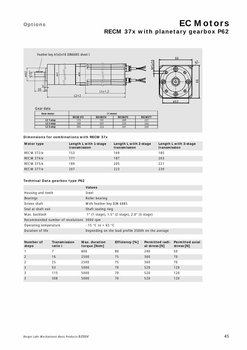
Options EC MotorsRECM 37x with planetary gearbox P62
Berger Lahr Mechatronic Basis Products 8/2004 45
Dimensions for combinations with RECM 37x
Technical Data gearbox type P62
Motor type Length L with 1-stage transmission
Length L with 2-stage transmission
Length L with 3-stage transmission
RECM 372/x 153 169 185
RECM 374/x 171 187 203
RECM 375/x 189 205 221
RECM 377/x 207 223 239
Values
Housing and teeth Steel
Bearings Roller bearing
Driven shaft With feather key DIN 6885
Seal at shaft exit Shaft sealing ring
Max. backlash 1° (1-stage), 1.5° (2-stage), 2.0° (3-stage)
Recommended number of revolutions 3000 rpm
Operating temperature - 15 C to + 65 C
Duration of life Depending on the load profile 3500h on the average
Feather key A5x5x18 DIN6885 sheet I
30 9
5
L2+2L1±1.2
ø66
ø62
ø14h
7
ø40j
7
M5x
10
ø52
66
R766
Gear dataGear motor
L2 1-stepL2 2-stepL2 3-step
173189205
191207223
209225241
227243259
RECM 372 RECM377RECM375RECM374L1 motor
Number of steps
Transmission ratio i
Max. duration torque [Ncm]
Efficiency [%] Permitted radi-al stress [N]
Permitted axial stress [N]
1 7 800 80 240 50
2 16 2500 75 360 70
2 25 2500 75 360 70
3 93 5000 70 520 120
3 115 5000 70 520 120
3 308 5000 70 520 120
EC Motors Options
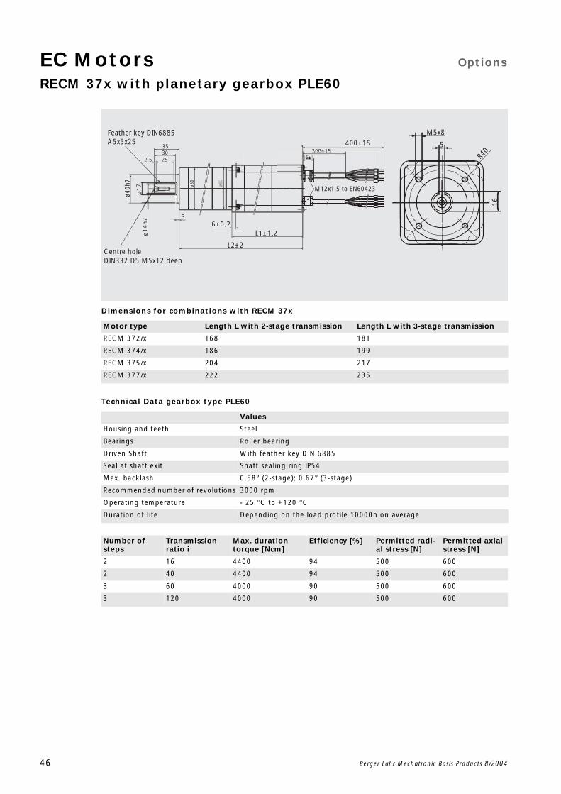
RECM 37x with planetary gearbox PLE60
46 Berger Lahr Mechatronic Basis Products 8/2004
Dimensions for combinations with RECM 37x
Technical Data gearbox type PLE60
Motor type Length L with 2-stage transmission Length L with 3-stage transmission
RECM 372/x 168 181
RECM 374/x 186 199
RECM 375/x 204 217
RECM 377/x 222 235
Values
Housing and teeth Steel
Bearings Roller bearing
Driven Shaft With feather key DIN 6885
Seal at shaft exit Shaft sealing ring IP54
Max. backlash 0.58° (2-stage); 0.67° (3-stage)
Recommended number of revolutions 3000 rpm
Operating temperature - 25 C to +120 C
Duration of life Depending on the load profile 10000h on average
3530
Centre holeDIN332 D5 M5x12 deep
Feather key DIN6885A5x5x25
36±0.2
L2±2
L1±1.2
M12x1.5 to EN60423
R40
5
M5x8
16
400±15300±15
ø60
ø40h
7
ø14h
7
Number of steps
Transmission ratio i
Max. duration torque [Ncm]
Efficiency [%] Permitted radi-al stress [N]
Permitted axial stress [N]
2 16 4400 94 500 600
2 40 4400 94 500 600
3 60 4000 90 500 600
3 120 4000 90 500 600
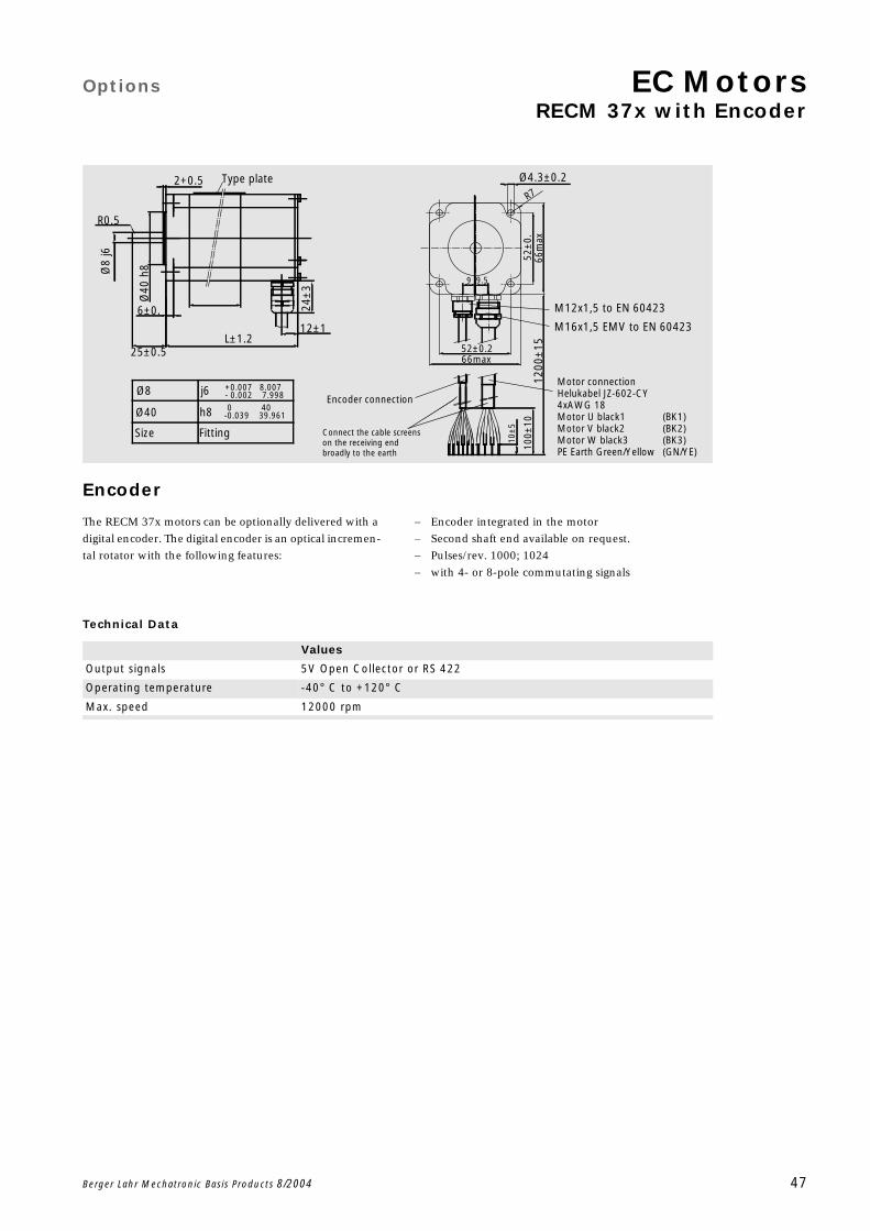
Options EC MotorsRECM 37x with Encoder
Berger Lahr Mechatronic Basis Products 8/2004 47
Encoder
The RECM 37x motors can be optionally delivered with a
digital encoder. The digital encoder is an optical incremen-
tal rotator with the following features:
Encoder integrated in the motor
Second shaft end available on request.
Pulses/rev. 1000; 1024
with 4- or 8-pole commutating signals
Technical Data
Type plate
M16x1,5 EMV to EN 60423
M12x1,5 to EN 60423
2+0.5
L±1.2
Ø8
j6
Ø40
h8
6±0.
25±0.5
R0.5
12±1
66max52±0.2
66m
ax52
±0.
9.59
Ø4.3±0.2
R7
1200
±15
10±
5
100±
10
24±
3
Encoder connection
Connect the cable screens on the receiving end broadly to the earth
Ø40 h8
Ø8 j6
Size Fitting
Motor connectionHelukabel JZ-602-CY4xAWG 18Motor U black1 (BK1)Motor V black2 (BK2)Motor W black3 (BK3)PE Earth Green/Yellow (GN/YE)
-0 40-0.039 39.961
+0.007 8.007- 0.002 7.998
Values
Output signals 5V Open Collector or RS 422
Operating temperature -40° C to +120° C
Max. speed 12000 rpm
EC Motors Options
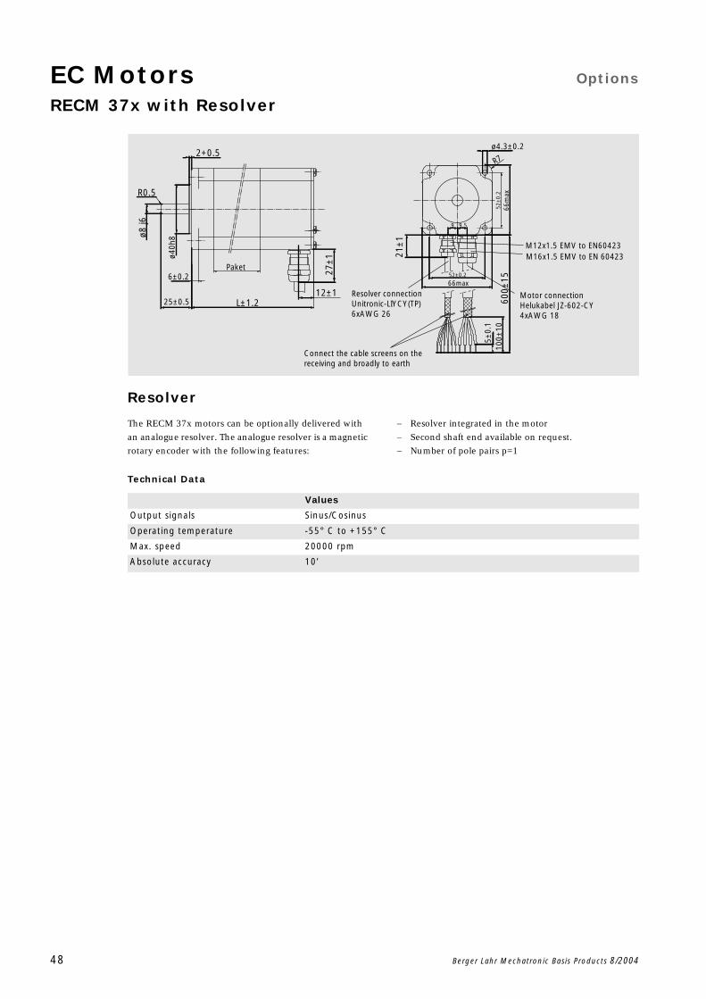
RECM 37x with Resolver
48 Berger Lahr Mechatronic Basis Products 8/2004
Resolver
The RECM 37x motors can be optionally delivered with
an analogue resolver. The analogue resolver is a magnetic
rotary encoder with the following features:
Resolver integrated in the motor
Second shaft end available on request.
Number of pole pairs p=1
Technical Data
2+0.5
Paket
R0.5
12±1L±1.225±0.5
6±0.2
9.59
R7
M12x1.5 EMV to EN60423M16x1.5 EMV to EN 60423
Motor connectionHelukabel JZ-602-CY4xAWG 18
Resolver connectionUnitronic-LIYCY(TP)6xAWG 26
66max52±0.2
Connect the cable screens on the receiving and broadly to earth
21±
1
5±0.
1
66m
ax52
±0.
2
ø4.3±0.2
600±
1510
0±10
27±
1ø40h
8ø8 j6
Values
Output signals Sinus/Cosinus
Operating temperature -55° C to +155° C
Max. speed 20000 rpm
Absolute accuracy 10’
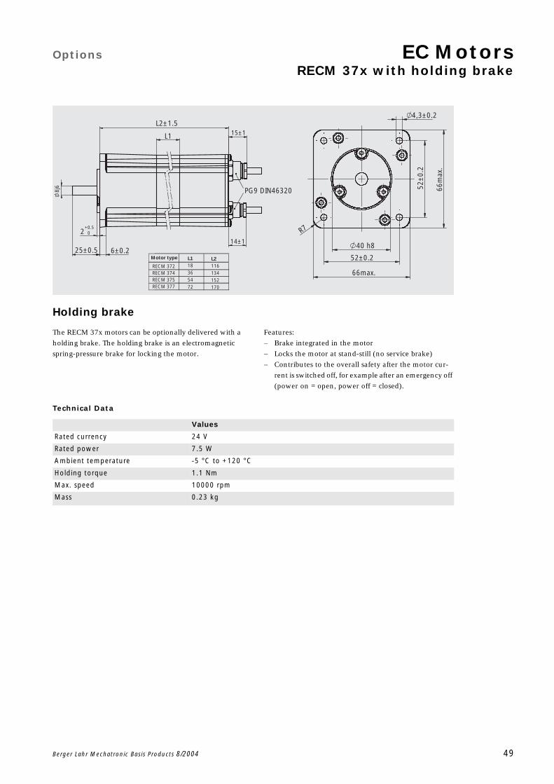
Options EC MotorsRECM 37x with holding brake
Berger Lahr Mechatronic Basis Products 8/2004 49
Holding brake
The RECM 37x motors can be optionally delivered with a
holding brake. The holding brake is an electromagnetic
spring-pressure brake for locking the motor.
Features:
Brake integrated in the motor
Locks the motor at stand-still (no service brake)
Contributes to the overall safety after the motor cur-
rent is switched off, for example after an emergency off
(power on = open, power off = closed).
Technical Data
PG9 DIN46320
14±1
6±0.225±0.5
L2±1.5
L1
52±0.2
52±
0.2
2+0.5 +0
15±1
8j6
66max.
66m
ax.
R7
40 h8
4,3±0.2
RECM 372 RECM 374RECM 375RECM 377
Motor type L118 36 54 72
L2116 134 152 170
Values
Rated currency 24 V
Rated power 7.5 W
Ambient temperature -5 °C to +120 °C
Holding torque 1.1 Nm
Max. speed 10000 rpm
Mass 0.23 kg

50 Berger Lahr Mechatronic Basis Products 8/2004
2-phase stepping motors
Berger Lahr Mechatronic Basic Products 8/2004 51
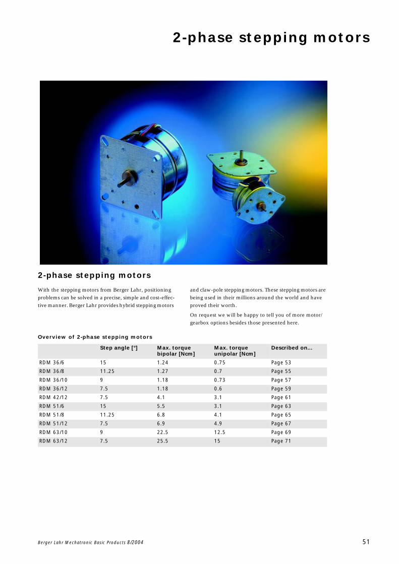
2-phase stepping motors
With the stepping motors from Berger Lahr, positioning
problems can be solved in a precise, simple and cost-effec-
tive manner. Berger Lahr provides hybrid stepping motors
and claw-pole stepping motors. These stepping motors are
being used in their millions around the world and have
proved their worth.
On request we will be happy to tell you of more motor/
gearbox options besides those presented here.
Overview of 2-phase stepping motors
Step angle [°] Max. torque bipolar [Ncm]
Max. torque unipolar [Ncm]
Described on...
RDM 36/6 15 1.24 0.75 Page 53
RDM 36/8 11.25 1.27 0.7 Page 55
RDM 36/10 9 1.18 0.73 Page 57
RDM 36/12 7.5 1.18 0.6 Page 59
RDM 42/12 7.5 4.1 3.1 Page 61
RDM 51/6 15 5.5 3.1 Page 63
RDM 51/8 11.25 6.8 4.1 Page 65
RDM 51/12 7.5 6.9 4.9 Page 67
RDM 63/10 9 22.5 12.5 Page 69
RDM 63/12 7.5 25.5 15 Page 71
2-phase stepping motors
52 Berger Lahr Mechatronic Basic Products 8/2004
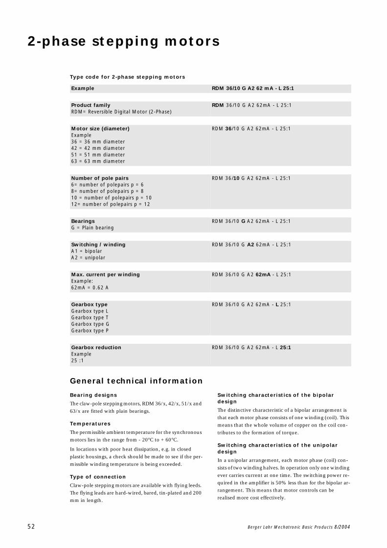
Type code for 2-phase stepping motors
General technical information
Bearing designs
The claw-pole stepping motors, RDM 36/x, 42/x, 51/x and
63/x are fitted with plain bearings.
Temperatures
The permissible ambient temperature for the synchronous
motors lies in the range from - 20C to + 60C.
In locations with poor heat dissipation, e.g. in closed
plastic housings, a check should be made to see if the per-
missible winding temperature is being exceeded.
Type of connection
Claw-pole stepping motors are available with flying leeds.
The flying leads are hard-wired, bared, tin-plated and 200
mm in length.
Switching characteristics of the bipolar design
The distinctive characteristic of a bipolar arrangement is
that each motor phase consists of one winding (coil). This
means that the whole volume of copper on the coil con-
tributes to the formation of torque.
Switching characteristics of the unipolar design
In a unipolar arrangement, each motor phase (coil) con-
sists of two winding halves. In operation only one winding
ever carries current at one time. The switching power re-
quired in the amplifier is 50% less than for the bipolar ar-
rangement. This means that motor controls can be
realised more cost effectively.
Example RDM 36/10 G A2 62 mA - L 25:1
Product familyRDM= Reversible Digital Motor (2-Phase)
RDM 36/10 G A2 62mA - L 25:1
Motor size (diameter)Example36 = 36 mm diameter42 = 42 mm diameter51 = 51 mm diameter63 = 63 mm diameter
RDM 36/10 G A2 62mA - L 25:1
Number of pole pairs6= number of polepairs p = 68= number of polepairs p = 810 = number of polepairs p = 1012= number of polepairs p = 12
RDM 36/10 G A2 62mA - L 25:1
BearingsG = Plain bearing
RDM 36/10 G A2 62mA - L 25:1
Switching / windingA1 = bipolarA2 = unipolar
RDM 36/10 G A2 62mA - L 25:1
Max. current per windingExample:62mA = 0.62 A
RDM 36/10 G A2 62mA - L 25:1
Gearbox typeGearbox type LGearbox type TGearbox type GGearbox type P
RDM 36/10 G A2 62mA - L 25:1
Gearbox reductionExample25 :1
RDM 36/10 G A2 62mA - L 25:1
Technical data 2-phase stepping motorsRDM 36/6
Berger Lahr Mechatronic Basic Products 8/2004 53
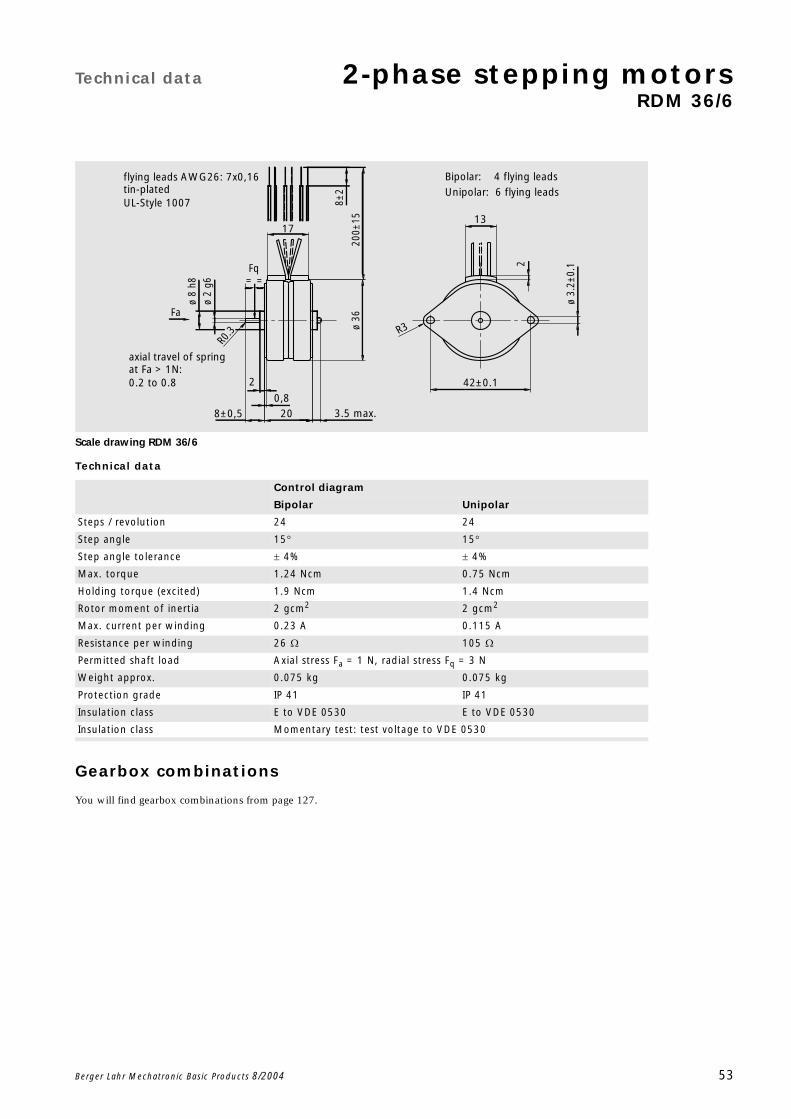
Scale drawing RDM 36/6
Technical data
Gearbox combinations
You will find gearbox combinations from page 127.
Control diagram
Bipolar Unipolar
Steps / revolution 24 24
Step angle 15 15
Step angle tolerance 4% 4%
Max. torque 1.24 Ncm 0.75 Ncm
Holding torque (excited) 1.9 Ncm 1.4 Ncm
Rotor moment of inertia 2 gcm2 2 gcm2
Max. current per winding 0.23 A 0.115 A
Resistance per winding 26 105
Permitted shaft load Axial stress Fa = 1 N, radial stress Fq = 3 N
Weight approx. 0.075 kg 0.075 kg
Protection grade IP 41 IP 41
Insulation class E to VDE 0530 E to VDE 0530
Insulation class Momentary test: test voltage to VDE 0530
R0.3
ø 3.
2±0.
12
8±2
2
3.5 max.
ø 2
g613
R3
42±0.1
17
ø 8
h8
ø 36
200±
15
0,8
8±0,5 20
UL-Style 1007
0.2 to 0.8
Unipolar: 6 flying leads
Bipolar: 4 flying leads flying leads AWG26: 7x0,16tin-plated
at Fa > 1N:axial travel of spring
Fq
Fa
==
2-phase stepping motors Technical data
RDM 36/6
54 Berger Lahr Mechatronic Basic Products 8/2004
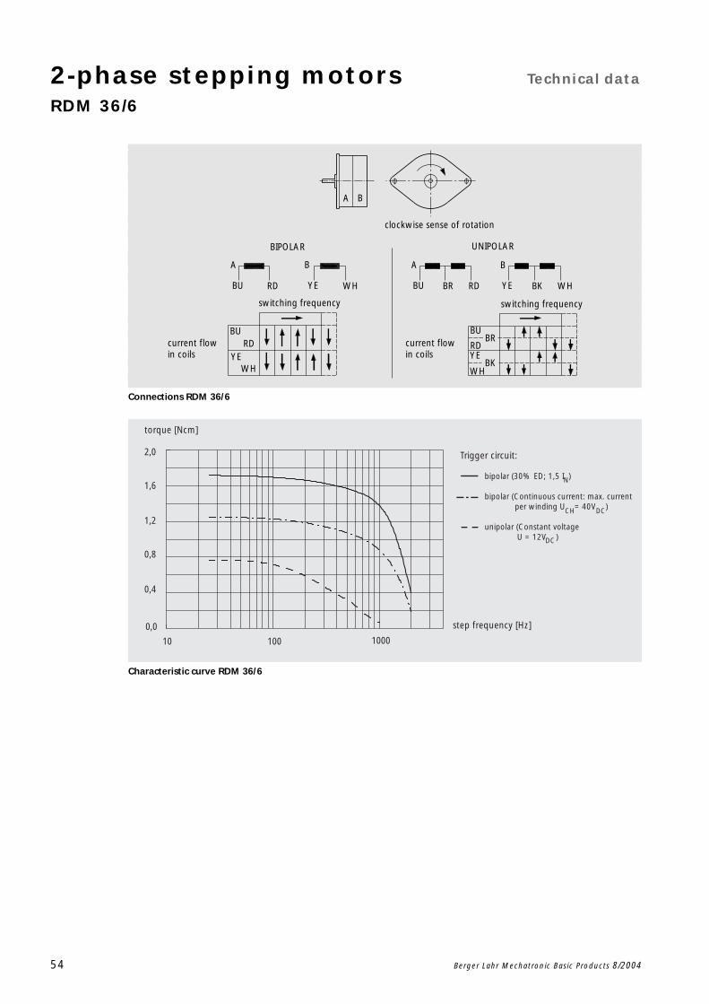
Connections RDM 36/6
Characteristic curve RDM 36/6
current flow in coils
current flow in coils
BKYE
B
clockwise sense of rotation
RDBRBU
A
UNIPOLAR
WH
switching frequency
A B
WHYE
B
RD
BIPOLAR
A
BU
switching frequency
BRBU
RDYE
BKWH
BURD
WHYE
10 100 1000
0,0
0,4
0,8
1,2
1,6
2,0
step frequency [Hz]
torque [Ncm]
N
Trigger circuit:
bipolar (30% ED; 1,5 I )
bipolar (Continuous current: max. current per winding U = 40V )
unipolar (Constant voltage U = 12V )
CH DC
DC
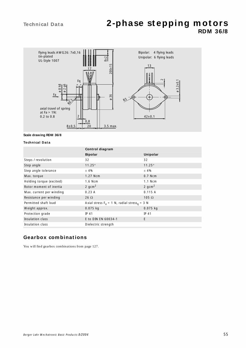
Technical Data 2-phase stepping motorsRDM 36/8
Berger Lahr Mechatronic Basic Products 8/2004 55
Scale drawing RDM 36/8
Technical Data
Gearbox combinations
You will find gearbox combinations from page 127.
Control diagram
Bipolar Unipolar
Steps / revolution 32 32
Step angle 11.25 11.25
Step angle tolerance 4% 4%
Max. torque 1.27 Ncm 0.7 Ncm
Holding torque (excited) 1.6 Ncm 1.1 Ncm
Rotor moment of inertia 2 gcm2 2 gcm2
Max. current per winding 0.23 A 0.115 A
Resistance per winding 26 105
Permitted shaft load Axial stress Fa = 1 N, radial stressq = 3 N
Weight approx. 0.075 kg 0.075 kg
Protection grade IP 41 IP 41
Insulation class E to DIN EN 60034-1 E
Insulation class Dielectric strength
R0.3
ø 3.
2±0.
12
8±2
2
3.5 max.
ø 2
g613
R3
42±0.1
17
ø 8
h8
ø 36
200±
15
0,8
8±0,5 20
UL-Style 1007
0.2 to 0.8
Unipolar: 6 flying leads
Bipolar: 4 flying leads flying leads AWG26: 7x0,16tin-plated
at Fa > 1N:axial travel of spring
Fq
Fa
==

2-phase stepping motors Technical Data
RDM 36/8
56 Berger Lahr Mechatronic Basic Products 8/2004
Connections RDM 36/8
Characteristic curve RDM 36/8
current flow in coils
current flow in coils
BKYE
B
clockwise sense of rotation
RDBRBU
A
UNIPOLAR
WH
switching frequency
A B
WHYE
B
RD
BIPOLAR
A
BU
switching frequency
BRBU
RDYE
BKWH
BURD
WHYE
10 100 1000500 20000,0
0,4
0,8
1,2
1,6
2,0
step frequency [Hz]
torque [Ncm]
N
Trigger circuit:
bipolar (30% ED; 1,5 I )
bipolar (Continuous current: max. current per winding U = 40V )
unipolar (Constant voltage U = 12V )
CH DC
DC

Technical Data 2-phase stepping motorsRDM 36/10
Berger Lahr Mechatronic Basic Products 8/2004 57
Scale drawing RDM 36/10
Technical Data
Gearbox combinations
You will find gearbox combinations from page 127.
Control diagram
Bipolar Unipolar
Steps / revolution 40 40
Step angle 9 9
Step angle tolerance 5% 6%
Max. torque 1.18 Ncm 0.73 Ncm
Holding torque (excited) 1.6 Ncm 1.0 Ncm
Rotor moment of inertia 2 gcm2 2 gcm2
Max. current per winding 0.23 A 0.115 A
Resistance per winding 26 105
Permitted shaft load Axial stress F a = 1 N, radial stress Fq = 3 N
Weight approx. 0.075 kg 0.075 kg
Protection grade IP 41 to DIN EN 60529 IP 41
Insulation class E to DIN EN 60034-1 E
Dielectric strength Momentary test: test voltage to DIN EN 60034-1
R0.3
ø 3.
2±0.
12
8±2
2
3.5 max.
ø 2
g613
R3
42±0.1
17
ø 8
h8
ø 36
200±
15
0,8
8±0,5 20
UL-Style 1007
0.2 to 0.8
Unipolar: 6 flying leads
Bipolar: 4 flying leads flying leads AWG26: 7x0,16tin-plated
at Fa > 1N:axial travel of spring
Fq
Fa
==

2-phase stepping motors Technical Data
RDM 36/10
58 Berger Lahr Mechatronic Basic Products 8/2004
Connections RDM 36/10
Characteristic curve RDM 36/10
current flow in coils
current flow in coils
BKYE
B
clockwise sense of rotation
RDBRBU
A
UNIPOLAR
WH
switching frequency
A B
WHYE
B
RD
BIPOLAR
A
BU
switching frequency
BRBU
RDYE
BKWH
BURD
WHYE
10 100 1000500 20000,0
0,4
0,8
1,2
1,6
step frequency [Hz]
torque [Ncm]
N
Trigger circuit:
bipolar (30% ED; 1,5 I )
bipolar (Continuous current: max. current per winding U = 40V )
unipolar (Constant voltage U = 12V )
CH DC
DC

Technical Data 2-phase stepping motorsRDM 36/12
Berger Lahr Mechatronic Basic Products 8/2004 59
Scale drawing RDM 36/12
Technical Data
Gearbox combinations
You will find gearbox combinations from page 127.
Control diagram
Bipolar Unipolar
Steps / revolution 48 48
Step angle 7.5 7.5
Step angle tolerance 5% 6%
Max. torque 1.18 Ncm 0.6 Ncm
Holding torque (excited) 1.6 Ncm 0.9 Ncm
Rotor moment of inertia 2 gcm2 2 gcm2
Max. current per winding 0.23 A 0.115 A
Resistance per winding 26 105
Permitted shaft load Axial stress Fa = 1 N, radial stress Fq = 3 N
Weight approx. 0.075 kg 0.075 kg
Protection grade IP 41 to DIN EN 60529 IP 41
Insulation class E to DIN EN 60034-1 E
Dielectric strength Momentary test: test voltage to DIN EN 60034-1
R0.3
ø 3.
2±0.
12
8±2
2
3.5 max.
ø 2
g613
R3
42±0.1
17
ø 8
h8
ø 36
200±
15
0,8
8±0,5 20
UL-Style 1007
0.2 to 0.8
Unipolar: 6 flying leads
Bipolar: 4 flying leads flying leads AWG26: 7x0,16tin-plated
at Fa > 1N:axial travel of spring
Fq
Fa
==
2-phase stepping motors Technical Data
RDM 36/12
60 Berger Lahr Mechatronic Basic Products 8/2004
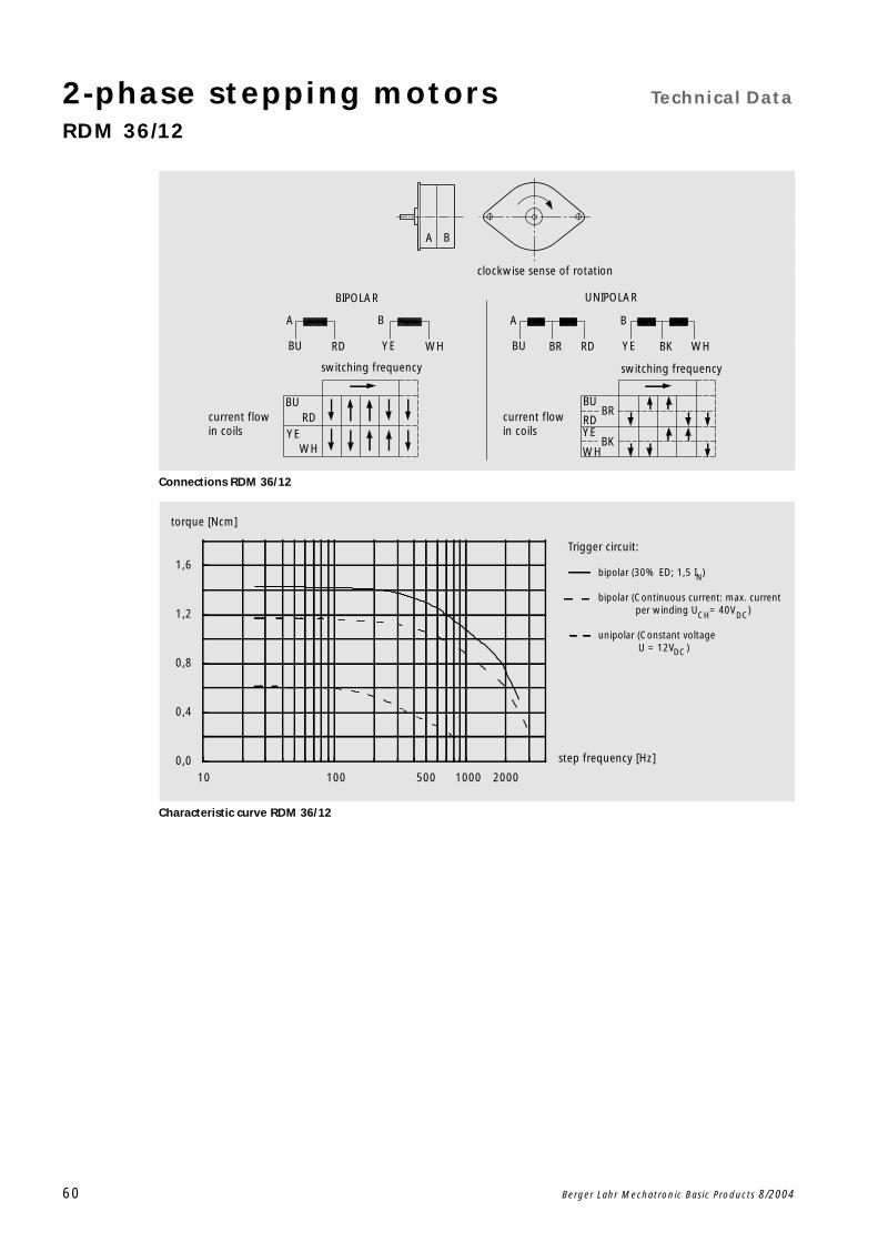
Connections RDM 36/12
Characteristic curve RDM 36/12
current flow in coils
current flow in coils
BKYE
B
clockwise sense of rotation
RDBRBU
A
UNIPOLAR
WH
switching frequency
A B
WHYE
B
RD
BIPOLAR
A
BU
switching frequency
BRBU
RDYE
BKWH
BURD
WHYE
10 100 1000500 20000,0
0,4
0,8
1,2
1,6
step frequency [Hz]
torque [Ncm]
N
Trigger circuit:
bipolar (30% ED; 1,5 I )
bipolar (Continuous current: max. current per winding U = 40V )
unipolar (Constant voltage U = 12V )
CH DC
DC
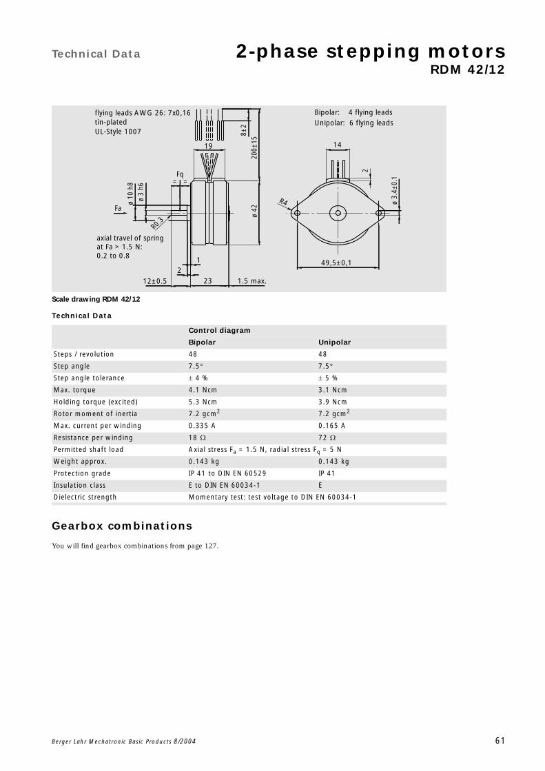
Technical Data 2-phase stepping motorsRDM 42/12
Berger Lahr Mechatronic Basic Products 8/2004 61
Scale drawing RDM 42/12
Technical Data
Gearbox combinations
You will find gearbox combinations from page 127.
Control diagram
Bipolar Unipolar
Steps / revolution 48 48
Step angle 7.5 7.5
Step angle tolerance 4 % 5 %
Max. torque 4.1 Ncm 3.1 Ncm
Holding torque (excited) 5.3 Ncm 3.9 Ncm
Rotor moment of inertia 7.2 gcm2 7.2 gcm2
Max. current per winding 0.335 A 0.165 A
Resistance per winding 18 72
Permitted shaft load Axial stress Fa = 1.5 N, radial stress Fq = 5 N
Weight approx. 0.143 kg 0.143 kg
Protection grade IP 41 to DIN EN 60529 IP 41
Insulation class E to DIN EN 60034-1 E
Dielectric strength Momentary test: test voltage to DIN EN 60034-1
R0
.3
8±2
200±
15
2
12±0.5
ø 3
h6
R4 ø 3.
4±0.
1
14
49,5±0,1
2
1
19
ø 10
h8
23 1.5 max.
ø
42
UL-Style 1007
flying leads AWG 26: 7x0,16tin-plated
0.2 to 0.8
Unipolar: 6 flying leads Bipolar: 4 flying leads
at Fa > 1.5 N:axial travel of spring
Fq
Fa
==

2-phase stepping motors Technical Data
RDM 42/12
62 Berger Lahr Mechatronic Basic Products 8/2004
Connections RDM 42/12
Characteristic curve RDM 42/12
current flow in coils
current flow in coils
BKYE
B
clockwise sense of rotation
RDBRBU
A
UNIPOLAR
WH
switching frequency
A B
WHYE
B
RD
BIPOLAR
A
BU
switching frequency
BRBU
RDYE
BKWH
BURD
WHYE
10 100 500 1000
0
1
2
3
4
5
6
step frequency [Hz]
torque [Ncm]
N
Trigger circuit:
bipolar (30% ED; 1,5 I )
bipolar (Continuous current: max. current per winding U = 40V )
unipolar (Constant voltage U = 12V )
CH DC
DC
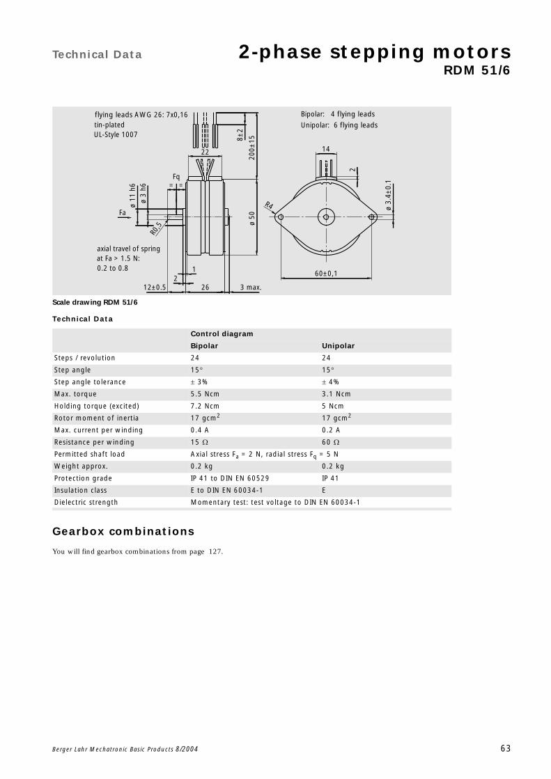
Technical Data 2-phase stepping motorsRDM 51/6
Berger Lahr Mechatronic Basic Products 8/2004 63
Scale drawing RDM 51/6
Technical Data
Gearbox combinations
You will find gearbox combinations from page 127.
Control diagram
Bipolar Unipolar
Steps / revolution 24 24
Step angle 15 15
Step angle tolerance 3% 4%
Max. torque 5.5 Ncm 3.1 Ncm
Holding torque (excited) 7.2 Ncm 5 Ncm
Rotor moment of inertia 17 gcm2 17 gcm2
Max. current per winding 0.4 A 0.2 A
Resistance per winding 15 60
Permitted shaft load Axial stress Fa = 2 N, radial stress Fq = 5 N
Weight approx. 0.2 kg 0.2 kg
Protection grade IP 41 to DIN EN 60529 IP 41
Insulation class E to DIN EN 60034-1 E
Dielectric strength Momentary test: test voltage to DIN EN 60034-1
R0,5
22
1
ø 3.
4±0.
1
2
R4
14
60±0,1
12±0.5 3 max.
ø 3
h6ø
11 h
6
ø 50
262
8±2
200±
15
UL-Style 1007
flying leads AWG 26: 7x0,16tin-plated
0.2 to 0.8
Unipolar: 6 flying leads
Bipolar: 4 flying leads
at Fa > 1.5 N:axial travel of spring
Fa
Fq==
2-phase stepping motors Technical Data
RDM 51/6
64 Berger Lahr Mechatronic Basic Products 8/2004
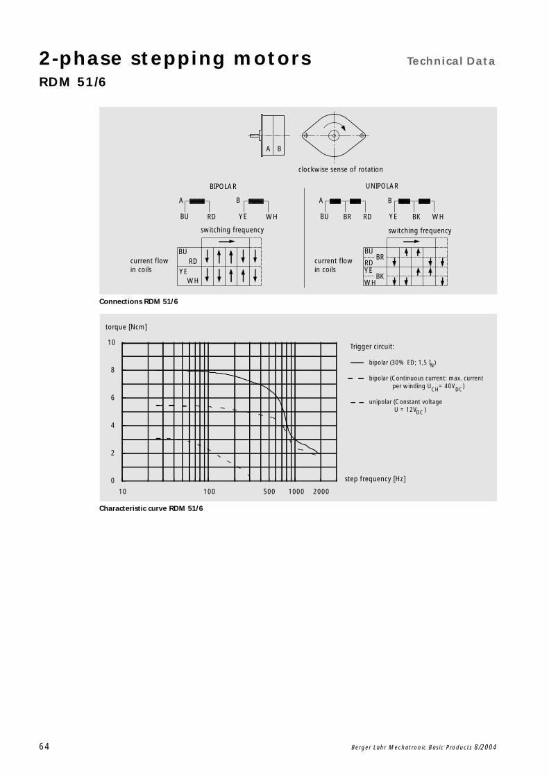
Connections RDM 51/6
Characteristic curve RDM 51/6
current flow in coils
current flow in coils
BKYE
B
clockwise sense of rotation
RDBRBU
A
UNIPOLAR
WH
switching frequency
A B
WHYE
B
RD
BIPOLAR
A
BU
switching frequency
BRBU
RDYE
BKWH
BURD
WHYE
10 100 1000500 2000
0
2
4
6
8
10
step frequency [Hz]
torque [Ncm]
N
Trigger circuit:
bipolar (30% ED; 1,5 I )
bipolar (Continuous current: max. current per winding U = 40V )
unipolar (Constant voltage U = 12V )
CH DC
DC

Technical Data 2-phase stepping motorsRDM 51/8
Berger Lahr Mechatronic Basic Products 8/2004 65
Scale drawing RDM 51/8
Technical Data
Gearbox combinations
You will find gearbox combinations from page 127.
Control diagram
Bipolar Unipolar
Steps / revolution 32 32
Step angle 11.25 11.25
Step angle tolerance 3% 4%
Max. torque 6.8 Ncm 4.1 Ncm
Holding torque (excited) 8.2 Ncm 5.7 Ncm
Rotor moment of inertia 17 gcm2 17 gcm2
Max. current per winding 0.4 A 0.2 A
Resistance per winding 15 60
Permitted shaft load Axial stress Fa = 2 N, radial stress Fq = 5 N
Weight approx. 0.2 kg 0.2 kg
Protection grade IP 41 to DIN EN 60529 IP 41
Insulation class E to DIN EN 60034-1 E
Dielectric strength Momentary test: test voltage to DIN EN 60034-1
R0,5
22
1
ø 3.
4±0.
1
2
R4
14
60±0,1
12±0.5 3 max.
ø 3
h6ø
11 h
6
ø 50
262
8±2
200±
15
UL-Style 1007
flying leads AWG 26: 7x0,16tin-plated
0.2 to 0.8
Unipolar: 6 flying leads
Bipolar: 4 flying leads
at Fa > 1.5 N:axial travel of spring
Fa
Fq==

2-phase stepping motors Technical Data
RDM 51/8
66 Berger Lahr Mechatronic Basic Products 8/2004
Connections RDM 51/8
Characteristic curve RDM 51/8
current flow in coils
current flow in coils
BKYE
B
clockwise sense of rotation
RDBRBU
A
UNIPOLAR
WH
switching frequency
A B
WHYE
B
RD
BIPOLAR
A
BU
switching frequency
BRBU
RDYE
BKWH
BURD
WHYE
10 100 500 1000
0
2
4
6
8
10
12
step frequency [Hz]
torque [Ncm]
N
Trigger circuit:
bipolar (30% ED; 1,5 I )
bipolar (Continuous current: max. current per winding U = 40V )
unipolar (Constant voltage U = 12V )
CH DC
DC

Technical Data 2-phase stepping motorsRDM 51/12
Berger Lahr Mechatronic Basic Products 8/2004 67
Scale drawing RDM 51/12
Technical Data
Gearbox combinations
You will find gearbox combinations from page 127.
Control diagram
Bipolar Unipolar
Steps / revolution 48 48
Step angle 7.5 7.5
Step angle tolerance 3% 4%
Max. torque 6.9 Ncm 4.9 Ncm
Holding torque (excited) 8.8 Ncm 6.2 Ncm
Rotor moment of inertia 17 gcm2 17 gcm2
Max. current per winding 0.4 A 0.2 A
Resistance per winding 15 60
Permitted shaft load Axial stress Fa = 2 N, radial stress Fq = 5 N
Weight approx. 0.2 kg 0.2 kg
Protection grade IP 41 to DIN EN 60529 IP 41
Insulation class E to DIN EN 60034-1 E
Dielectric strength Momentary test: test voltage to DIN EN 60034-1
R0,5
22
1
ø 3.
4±0.
1
2
R4
14
60±0,1
12±0.5 3 max.
ø 3
h6ø
11 h
6
ø 50
262
8±2
200±
15
UL-Style 1007
flying leads AWG 26: 7x0,16tin-plated
0.2 to 0.8
Unipolar: 6 flying leads
Bipolar: 4 flying leads
at Fa > 1.5 N:axial travel of spring
Fa
Fq==

2-phase stepping motors Technical Data
RDM 51/12
68 Berger Lahr Mechatronic Basic Products 8/2004
Connections RDM 51/12
Characteristic curve RDM 51/12
current flow in coils
current flow in coils
BKYE
B
clockwise sense of rotation
RDBRBU
A
UNIPOLAR
WH
switching frequency
A B
WHYE
B
RD
BIPOLAR
A
BU
switching frequency
BRBU
RDYE
BKWH
BURD
WHYE
10 100 500 1000
0
2
4
6
8
10
12
step frecuency [Hz]
torque [Ncm]
N
Trigger circuit:
bipolar (30% ED; 1,5 I )
bipolar (Continuous current: max. current per winding U = 40V )
unipolar (Constant voltage U = 12V )
CH DC
DC

Technical Data 2-phase stepping motorsRDM 63/10
Berger Lahr Mechatronic Basic Products 8/2004 69
Scale drawing RDM 63/10
Technical Data
Gearbox combinations
You will find gearbox combinations from page 127.
Control diagram
Bipolar Unipolar
Steps / revolution 40 40
Step angle 9 9
Step angle tolerance 3% 4%
Max. torque 22.5 Ncm 12.5 Ncm
Holding torque (excited) 29 Ncm 20 Ncm
Rotor moment of inertia 150 gcm2 150 gcm2
Max. current per winding 0.65 A 0.31 A
Resistance per winding 9.6 41
Permitted shaft load Axial stress Fa = 3 N, radial stress Fq = 10 N
Weight approx. 0.46 kg 0.46 kg
Protection grade IP 41 to DIN EN 60529 IP 41
Insulation class E to DIN EN 60034-1 E
Dielectric strength Momentary test: test voltage to DIN EN 60034-1
4.50.1
644 max
8±2
200±
15
±0.5
ø4
h6
R4
7
3
ø14
h6
ø 64
4
42
UL-Style 1007
flying leads AWG 26: 7x0,16tin plated
0,2 bis 0,8
Unipolar: 6 flying leadsBipolar: 4 flying leads
at Fa > 3N:axial travel of spring
Fq
Fa

2-phase stepping motors Technical Data
RDM 63/10
70 Berger Lahr Mechatronic Basic Products 8/2004
Connections RDM 63/10
Characteristic curve RDM 63/10
current flow in coils
current flow in coils
BKYE
B
clockwise sense of rotation
RDBRBU
A
UNIPOLAR
WH
switching frequency
A B
WHYE
B
RD
BIPOLAR
A
BU
switching frequency
BRBU
RDYE
BKWH
BURD
WHYE
10 100 500 1000
0
5
10
15
20
25
30
35
step frecuency [Hz]
torque [Ncm]
N
Trigger circuit:
bipolar (30% ED; 1,5 I )
bipolar (Continuous current: max. current per winding U = 40V )
unipolar (Constant voltage U = 12V )
CH DC
DC
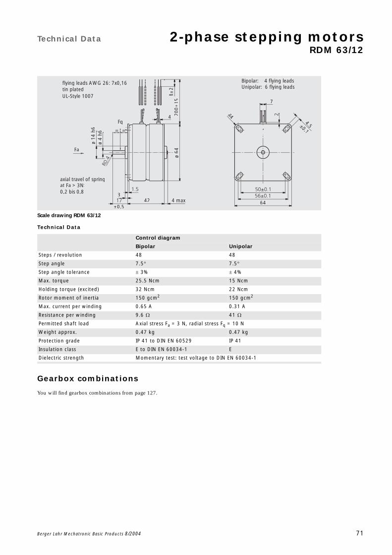
Technical Data 2-phase stepping motorsRDM 63/12
Berger Lahr Mechatronic Basic Products 8/2004 71
Scale drawing RDM 63/12
Technical Data
Gearbox combinations
You will find gearbox combinations from page 127.
Control diagram
Bipolar Unipolar
Steps / revolution 48 48
Step angle 7.5 7.5
Step angle tolerance 3% 4%
Max. torque 25.5 Ncm 15 Ncm
Holding torque (excited) 32 Ncm 22 Ncm
Rotor moment of inertia 150 gcm2 150 gcm2
Max. current per winding 0.65 A 0.31 A
Resistance per winding 9.6 41
Permitted shaft load Axial stress Fa = 3 N, radial stress Fq = 10 N
Weight approx. 0.47 kg 0.47 kg
Protection grade IP 41 to DIN EN 60529 IP 41
Insulation class E to DIN EN 60034-1 E
Dielectric strength Momentary test: test voltage to DIN EN 60034-1
4.50.1
644 max
8±2
200±
15
±0.5
ø4
h6
R4
7
3
ø14
h6
ø 64
4
42
UL-Style 1007
flying leads AWG 26: 7x0,16tin plated
0,2 bis 0,8
Unipolar: 6 flying leadsBipolar: 4 flying leads
at Fa > 3N:axial travel of spring
Fq
Fa
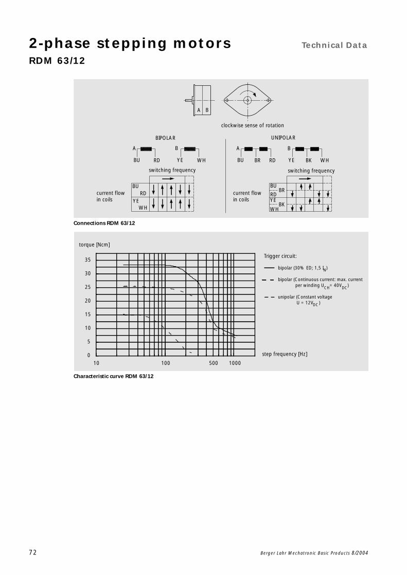
2-phase stepping motors Technical Data
RDM 63/12
72 Berger Lahr Mechatronic Basic Products 8/2004
Connections RDM 63/12
Characteristic curve RDM 63/12
current flow in coils
current flow in coils
BKYE
B
clockwise sense of rotation
RDBRBU
A
UNIPOLAR
WH
switching frequency
A B
WHYE
B
RD
BIPOLAR
A
BU
switching frequency
BRBU
RDYE
BKWH
BURD
WHYE
10 100 500 10000
5
10
15
20
25
30
35
step frequency [Hz]
torque [Ncm]
N
Trigger circuit:
bipolar (30% ED; 1,5 I )
bipolar (Continuous current: max. current per winding U = 40V )
unipolar (Constant voltage U = 12V )
CH DC
DC
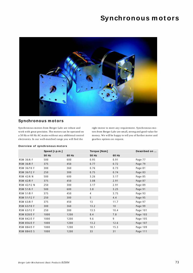
Synchronous motors
Berger Lahr Mechatronic Basic Products 8/2004 73
Synchronous motors
Synchronous motors from Berger Lahr are robust and
work with great precision. The motors can be operated on
a 50 Hz or 60 Hz AC mains without any additional control
electronics. In our well-matched range you will find the
right motor to meet any requirement. Synchronous mo-
tors from Berger Lahr are small, strong and good value for
money. We will be happy to tell you of further motor and
gearbox options on request.
Overview of synchronous motors
Speed [r.p.m.] Torque [Ncm] Described on ...
50 Hz 60 Hz 50 Hz 60 Hz
RSM 36/6 F 500 600 0.95 0.91 Page 77
RSM 36/8 F 375 450 0.77 0.72 Page 79
RSM 36/10 F 300 360 0.76 0.73 Page 81
RSM 36/12 F 250 300 0.75 0.74 Page 83
RSM 42/6 N 500 600 3.26 3.17 Page 85
RSM 42/8 F 375 450 3.08 2.91 Page 87
RSM 42/12 N 250 300 3.17 2.91 Page 89
RSM 51/6 F 500 600 3.8 3.25 Page 91
RSM 51/8 F 375 450 4 3.75 Page 93
RSM 51/12 F 250 300 5 4.4 Page 95
RSM 63/8 F 375 450 13 11.7 Page 97
RSM 63/10 F 300 360 13.2 10 Page 99
RSM 63/12 F 250 300 13.5 10.4 Page 101
RSM 828/3 F 1000 1200 8.4 7.8 Page 103
RSM 842/3 F 1000 1200 9.6 9 Page 105
RSM 856/3 F 1000 1200 13.2 12.6 Page 107
RSM 884/3 F 1000 1200 18.1 15.3 Page 109
RSM 884/3 S 1000 1200 33 31 Page 111
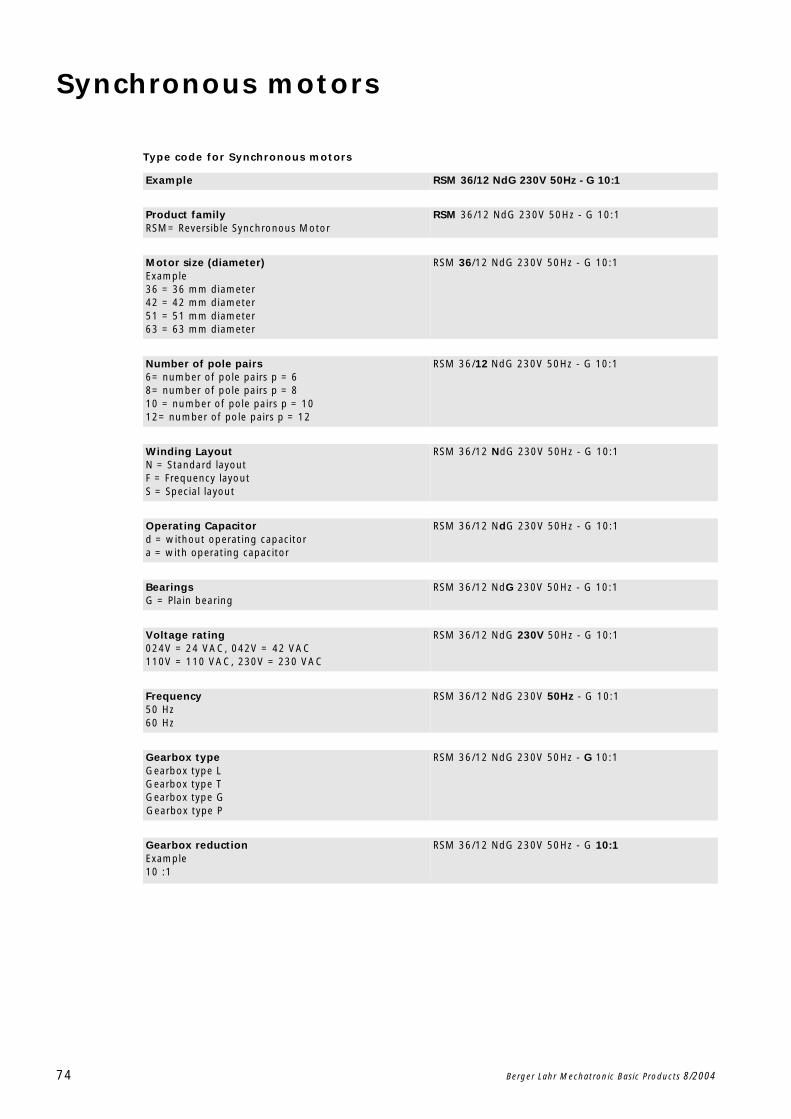
Synchronous motors
74 Berger Lahr Mechatronic Basic Products 8/2004
Type code for Synchronous motors
Example RSM 36/12 NdG 230V 50Hz - G 10:1
Product familyRSM= Reversible Synchronous Motor
RSM 36/12 NdG 230V 50Hz - G 10:1
Motor size (diameter)Example36 = 36 mm diameter42 = 42 mm diameter51 = 51 mm diameter63 = 63 mm diameter
RSM 36/12 NdG 230V 50Hz - G 10:1
Number of pole pairs6= number of pole pairs p = 68= number of pole pairs p = 810 = number of pole pairs p = 1012= number of pole pairs p = 12
RSM 36/12 NdG 230V 50Hz - G 10:1
Winding LayoutN = Standard layoutF = Frequency layoutS = Special layout
RSM 36/12 NdG 230V 50Hz - G 10:1
Operating Capacitord = without operating capacitora = with operating capacitor
RSM 36/12 NdG 230V 50Hz - G 10:1
BearingsG = Plain bearing
RSM 36/12 NdG 230V 50Hz - G 10:1
Voltage rating024V = 24 VAC, 042V = 42 VAC110V = 110 VAC, 230V = 230 VAC
RSM 36/12 NdG 230V 50Hz - G 10:1
Frequency50 Hz60 Hz
RSM 36/12 NdG 230V 50Hz - G 10:1
Gearbox typeGearbox type LGearbox type TGearbox type GGearbox type P
RSM 36/12 NdG 230V 50Hz - G 10:1
Gearbox reductionExample10 :1
RSM 36/12 NdG 230V 50Hz - G 10:1
Synchronous motors
Berger Lahr Mechatronic Basic Products 8/2004 75
General technical information
Bearing designs
Synchronous motors constructed on the claw-pole princi-
ple, RSM 36/x, 42/x, 51/x and 63/x, are fitted with plain
bearings, the packaged synchronous motors RSM 8xx
with ball bearings.
Temperatures
The permissible ambient temperature for the synchronous
motors lies in the range from -20C to +60C. In locations
with poor heat dissipation, e.g. in closed plastic housings,
a check should be made to see if the permissible winding
temperature is being exceeded.
Type of connection
The synchronous motors are available with flying leads.
The flying leads are hard-wired, bared, tin-plated and 200
mm in length. Packaged synchronous motors are available
with terminal boxes as standard.
Voltages
Synchronous motors are available depending on the type
for rated voltages of 24, 42, 110 and 230 VAC.
Windings
With the exception of the motors with S windings, the
synchronous motors are made to VDE 0530 in operating
mode S1 (continuous operation).
Normal design N: Motors of this design have different
capacitance values for 50 Hz and 60 Hz at the same op-
erating voltage.
Frequency design F: The same operating capacitors are
used for 50 Hz and 60 Hz at the same operating voltage.
Operating capacitors for all rated voltages are available as
an option. For all RSM 36 units an external device (capac-
itor or resistor) is required for the 230 V version. These are
also available as an option.

76 Berger Lahr Mechatronic Basic Products 8/2004
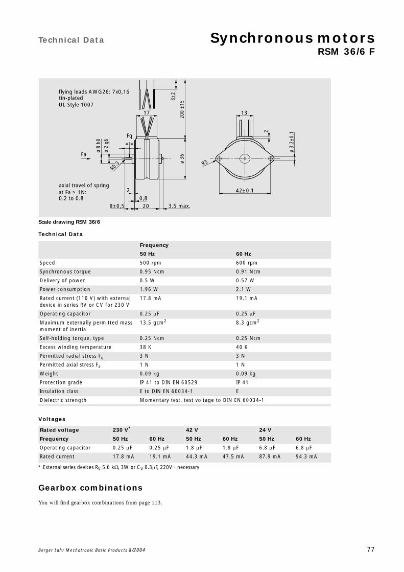
Technical Data Synchronous motorsRSM 36/6 F
Berger Lahr Mechatronic Basic Products 8/2004 77
Scale drawing RSM 36/6
Technical Data
Voltages
Gearbox combinations
You will find gearbox combinations from page 113.
Frequency
50 Hz 60 Hz
Speed 500 rpm 600 rpm
Synchronous torque 0.95 Ncm 0.91 Ncm
Delivery of power 0.5 W 0.57 W
Power consumption 1.96 W 2.1 W
Rated current (110 V) with external device in series RV or CV for 230 V
17.8 mA 19.1 mA
Operating capacitor 0.25 F 0.25 F
Maximum externally permitted mass moment of inertia
13.5 gcm2 8.3 gcm2
Self-holding torque, type 0.25 Ncm 0.25 Ncm
Excess winding temperature 38 K 40 K
Permitted radial stress Fq 3 N 3 N
Permitted axial stress Fa 1 N 1 N
Weight 0.09 kg 0.09 kg
Protection grade IP 41 to DIN EN 60529 IP 41
Insulation class E to DIN EN 60034-1 E
Dielectric strength Momentary test, test voltage to DIN EN 60034-1
Rated voltage 230 V*
* External series devices RV 5.6 k, 3W or CV 0.3F, 220V~ necessary
42 V 24 V
Frequency 50 Hz 60 Hz 50 Hz 60 Hz 50 Hz 60 Hz
Operating capacitor 0.25 F 0.25 F 1.8 F 1.8 F 6.8 F 6.8 F
Rated current 17.8 mA 19.1 mA 44.3 mA 47.5 mA 87.9 mA 94.3 mA
==
R0
.3
200
±158±
2
ø 3.
2±0.
12
2
3.5 max.
ø 2
g613
R3
42±0.1
17
ø 8
h8
ø 36
0,88±0,5 20
UL-Style 1007
0.2 to 0.8
Fq
tin-platedflying leads AWG26: 7x0,16
Fa
at Fa > 1N:axial travel of spring

Synchronous motors Technical Data
RSM 36/6 F
78 Berger Lahr Mechatronic Basic Products 8/2004
Connections RSM 36/6
Characteristic curve RSM 36/6 at 50 Hz
Characteristic curve RSM 36/6 at 60 Hz
2.)1.) 2.)
1.)N L1
I
IICB
RD
BU M
YE
switch position I = clockwise rotationswitch position II = anti-clockwise rotation
CB = operating capacitor
0,7 0,8 0,9 1,0 1,1 1,2 1,30,2
0,4
0,6
0,8
1,0
1,2
1,4
torque [Ncm]
operating voltage / rated voltage
0,7 0,8 0,9 1,0 1,1 1,2 1,30,2
0,4
0,6
0,8
1,0
1,2
1,4
torque [Ncm]
operating voltage / rated voltage

Technical Data Synchronous motorsRSM 36/8 F
Berger Lahr Mechatronic Basic Products 8/2004 79
Scale drawing RSM 36/8
Technical Data
Voltages
Gearbox combinations
You will find gearbox combinations from page 113.
Frequency
50 Hz 60 Hz
Speed 375 rpm 450 rpm
Synchronous torque 0.77 Ncm 0.72 Ncm
Delivery of power 0.3 W 0.34 W
Power consumption 1.1 W 1.2 W
Rated current (110 V) with external device in series RV or CV for 230 V
10 mA 10.6 mA
Operating capacitor 0.15 F 0.15 F
Maximum externally permitted mass moment of inertia
25.5 gcm2 8.8 gcm2
Self-holding torque, type 0.2 Ncm 0.2 Ncm
Excess winding temperature 20 K 27 K
Permitted radial stress Fq 3 N 3 N
Permitted axial stress Fa 1 N 1 N
Weight 0.09 kg 0.09 kg
Protection grade IP 41 to DIN EN 60529 IP 41
Insulation class E to DIN EN 60034-1 E
Dielectric strength Momentary test, test voltage to DIN EN 60034-1
Rated voltage 230 V*
* External series devices RV 10 k, 1.5 W or CV 0.15 F, 220V~ necessary
42 V 24 V
Frequency 50 Hz 60 Hz 50 Hz 60 Hz 50 Hz 60 Hz
Operating capacitor 0.15 F 0.15 F 1 F 1 F 3 F 3 F
Rated current 10 mA 10.6 mA 22.5 mA 23.9 mA 45.2 mA 47.9 mA
==
R0
.3
200
±158±
2
ø 3.
2±0.
12
2
3.5 max.
ø 2
g613
R3
42±0.1
17
ø 8
h8
ø 36
0,88±0,5 20
UL-Style 1007
0.2 to 0.8
Fq
tin-platedflying leads AWG26: 7x0,16
Fa
at Fa > 1N:axial travel of spring

Synchronous motors Technical Data
RSM 36/8 F
80 Berger Lahr Mechatronic Basic Products 8/2004
Connections RSM 36/8
Characteristic curve RSM 36/8 at 50 Hz
Characteristic curve RSM 36/8 at 60 Hz
2.)1.) 2.)
1.)N L1
I
IICB
RD
BU M
YE
switch position I = clockwise rotationswitch position II = anti-clockwise rotation
CB = operating capacitor
0,7 0,8 0,9 1,0 1,1 1,2 1,30,2
0,4
0,6
0,8
1,0
1,2
1,4
torque [Ncm]
operating voltage / rated voltage
0,7 0,8 0,9 1,0 1,1 1,2 1,30,2
0,4
0,6
0,8
1,0
1,2
1,4
torque [Ncm]
operating voltage / rated voltage

Technical Data Synchronous motorsRSM 36/10 F
Berger Lahr Mechatronic Basic Products 8/2004 81
Scale drawing RSM 36/10
Technical Data
Voltages
Gearbox combinations
You will find gearbox combinations from page 113.
Frequency
50 Hz 60 Hz
Speed 300 rpm 360 rpm
Synchronous torque 0.76 Ncm 0.73 Ncm
Delivery of power 0.24 W 0.28 W
Power consumption 1.05 W 1.1 W
Rated current (110 V) with external device in series RV or CV for 230 V
9.5 mA 10.2 mA
Operating capacitor 0.135 F 0.135 F
Maximum externally permitted mass moment of inertia
13.8 gcm2 10 gcm2
Self-holding torque, type 0.18 Ncm 0.18 Ncm
Excess winding temperature 22 K 29 K
Permitted radial stress Fq 3 N 3 N
Permitted axial stress Fa 1 N 1 N
Weight 0.09 kg 0.09 kg
Protection grade IP 41 to DIN EN 60529 IP 41
Insulation class E to DIN EN 60034-1 E
Dielectric strength Momentary test, test voltage to DIN EN 60034-1
Rated voltage 230 V*
* External series devices RV 15 k, 1.5 W oder CV 0.15 F, 220V~ notwendig
42 V 24 V
Frequency 50 Hz 60 Hz 50 Hz 60 Hz 50 Hz 60 Hz
Operating capacitor 0.135 F 0.135 F 0.68 F 0.68 F 2.2 F 2.2 F
Rated current 9.5 mA 10.2 mA 21.4 mA 23 mA 38 mA 40.8 mA
==
R0
.3
200
±158±
2
ø 3.
2±0.
12
2
3.5 max.
ø 2
g613
R3
42±0.1
17
ø 8
h8
ø 36
0,88±0,5 20
UL-Style 1007
0.2 to 0.8
Fq
tin-platedflying leads AWG26: 7x0,16
Fa
at Fa > 1N:axial travel of spring
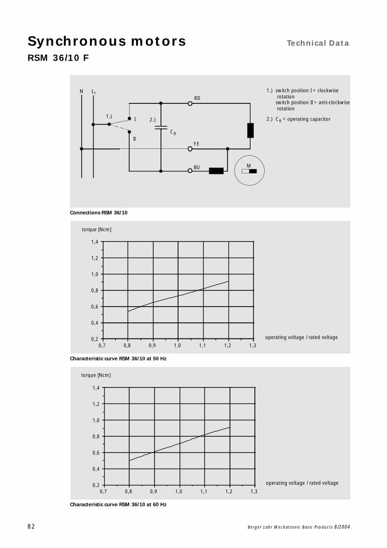
Synchronous motors Technical Data
RSM 36/10 F
82 Berger Lahr Mechatronic Basic Products 8/2004
Connections RSM 36/10
Characteristic curve RSM 36/10 at 50 Hz
Characteristic curve RSM 36/10 at 60 Hz
2.)1.) 2.)
1.)N L1
I
IICB
RD
BU M
YE
switch position I = clockwise rotationswitch position II = anti-clockwise rotation
CB = operating capacitor
0,7 0,8 0,9 1,0 1,1 1,2 1,30,2
0,4
0,6
0,8
1,0
1,2
1,4
torque [Ncm]
operating voltage / rated voltage
0,7 0,8 0,9 1,0 1,1 1,2 1,30,2
0,4
0,6
0,8
1,0
1,2
1,4
torque [Ncm]
operating voltage / rated voltage
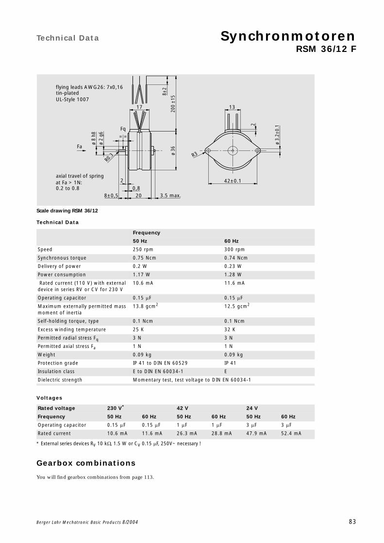
Technical Data SynchronmotorenRSM 36/12 F
Berger Lahr Mechatronic Basic Products 8/2004 83
Scale drawing RSM 36/12
Technical Data
Voltages
Gearbox combinations
You will find gearbox combinations from page 113.
Frequency
50 Hz 60 Hz
Speed 250 rpm 300 rpm
Synchronous torque 0.75 Ncm 0.74 Ncm
Delivery of power 0.2 W 0.23 W
Power consumption 1.17 W 1.28 W
Rated current (110 V) with external device in series RV or CV for 230 V
10.6 mA 11.6 mA
Operating capacitor 0.15 F 0.15 F
Maximum externally permitted mass moment of inertia
13.8 gcm2 12.5 gcm2
Self-holding torque, type 0.1 Ncm 0.1 Ncm
Excess winding temperature 25 K 32 K
Permitted radial stress Fq 3 N 3 N
Permitted axial stress Fa 1 N 1 N
Weight 0.09 kg 0.09 kg
Protection grade IP 41 to DIN EN 60529 IP 41
Insulation class E to DIN EN 60034-1 E
Dielectric strength Momentary test, test voltage to DIN EN 60034-1
Rated voltage 230 V*
* External series devices RV 10 k, 1.5 W or CV 0.15 F, 250V~ necessary !
42 V 24 V
Frequency 50 Hz 60 Hz 50 Hz 60 Hz 50 Hz 60 Hz
Operating capacitor 0.15 F 0.15 F 1 F 1 F 3 F 3 F
Rated current 10.6 mA 11.6 mA 26.3 mA 28.8 mA 47.9 mA 52.4 mA
==
R0
.3
200
±158±
2
ø 3.
2±0.
12
2
3.5 max.
ø 2
g613
R3
42±0.1
17
ø 8
h8
ø 36
0,88±0,5 20
UL-Style 1007
0.2 to 0.8
Fq
tin-platedflying leads AWG26: 7x0,16
Fa
at Fa > 1N:axial travel of spring
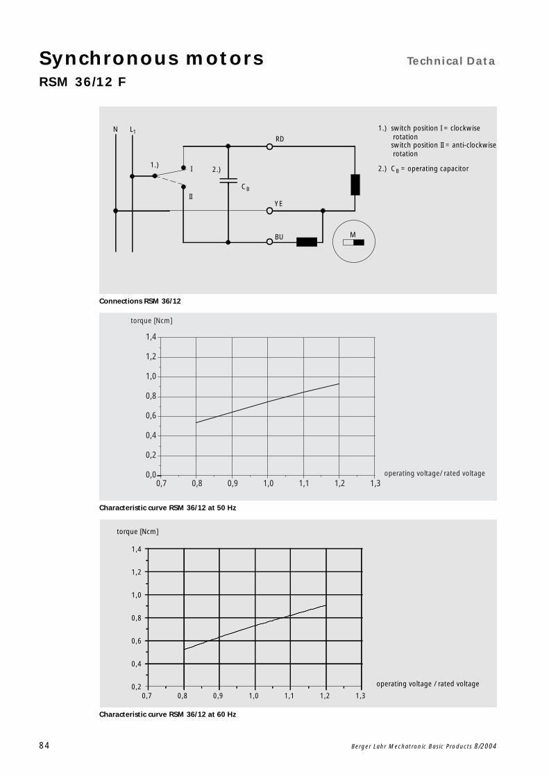
Synchronous motors Technical Data
RSM 36/12 F
84 Berger Lahr Mechatronic Basic Products 8/2004
Connections RSM 36/12
Characteristic curve RSM 36/12 at 50 Hz
Characteristic curve RSM 36/12 at 60 Hz
2.)1.) 2.)
1.)N L1
I
IICB
RD
BU M
YE
switch position I = clockwise rotationswitch position II = anti-clockwise rotation
CB = operating capacitor
0,7 0,8 0,9 1,0 1,1 1,2 1,30,0
0,2
0,4
0,6
0,8
1,0
1,2
1,4
torque [Ncm]
operating voltage/ rated voltage
0,7 0,8 0,9 1,0 1,1 1,2 1,30,2
0,4
0,6
0,8
1,0
1,2
1,4
torque [Ncm]
operating voltage / rated voltage

Technical Data Synchronous motorsRSM 42/6 N
Berger Lahr Mechatronic Basic Products 8/2004 85
Scale drawing RSM 42/6
Technical Data
Voltages
Gearbox combinations
You will find gearbox combinations from page 113.
Frequency
50 Hz 60 Hz
Speed 500rpm 600 rpm
Synchronous torque 3.41 Ncm 3.17 Ncm
Delivery of power 1.78 W 1.99 W
Power consumption 5.9 W 5.78 W
Rated current (230 V) 25.3 mA 24.6 mA
Operating capacitor 0.18 F 0.15 F
Maximum externally permitted mass moment of inertia
31 gcm2 25 gcm2
Self-holding torque, type 0.55 Ncm 0.55 Ncm
Excess winding temperature 74 K 72 K
Permitted radial stress Fq 5 N 5 N
Permitted axial stress Fa 1.5 N 1.5 N
Weight 0.15 kg 0.15 kg
Protection grade IP 41 to DIN EN 60529 IP 41
Insulation class E to DIN EN 60034-1 E
Dielectric strength Momentary test, test voltage to DIN EN 60034-1
Rated voltage 110 V 42 V 24 V
Frequency 50 Hz 60 Hz 50 Hz 60 Hz 50 Hz 60 Hz
Operating capacitor 0.68 F 0.56 F 5.6 F 4.7 F 14 F 12 F
Rated current 51.0 mA 49.6 mA 140 mA 137 mA 210 mA 221 mA
R0
.3
200±
15
8±2
212±0.5
ø 3
h6
R4 ø 3.
4±0.
1
14
49,5±0,1
2
1
19
ø 10
h8
23 1.5 max.
ø 42
UL-Style 1007
tin-plated
0.2 to 0.8
Fq
==
flying leads AWG 26: 7x0,16
Fa
at Fa > 1.5 N:axial travel of spring

Synchronous motors Technical Data
RSM 42/6 N
86 Berger Lahr Mechatronic Basic Products 8/2004
Connections RSM 42/6
Characteristic curve RSM 42/6 at 50 Hz
Characteristic curve RSM 42/6 at 60 Hz
2.)1.) 2.)
1.)N L1
I
IICB
RD
BU M
YE
switch position I = clockwise rotationswitch position II = anti-clockwise rotation
CB = operating capacitor
0,7 0,8 0,9 1,0 1,1 1,2 1,31,5
2,0
2,5
3,0
3,5
4,0
4,5
torque [Ncm]
operating voltage / rated voltage
0,7 0,8 0,9 1,0 1,1 1,2 1,31,5
2,0
2,5
3,0
3,5
4,0
4,5
torque [Ncm]
operating voltage / rated voltage
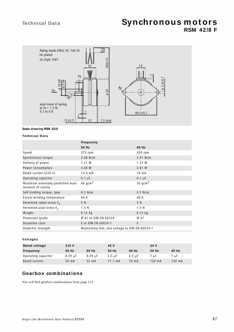
Technical Data Synchronous motorsRSM 42/8 F
Berger Lahr Mechatronic Basic Products 8/2004 87
Scale drawing RSM 42/8
Technical Data
Voltages
Gearbox combinations
You will find gearbox combinations from page 113.
Frequency
50 Hz 60 Hz
Speed 375 rpm 450 rpm
Synchronous torque 3.08 Ncm 2.91 Ncm
Delivery of power 1.21 W 1.37 W
Power consumption 3.44 W 3.81 W
Rated current (230 V) 14.4 mA 16 mA
Operating capacitor 0.1 F 0.1 F
Maximum externally permitted mass moment of inertia
46 gcm2 30 gcm2
Self-holding torque, type 0.5 Ncm 0.5 Ncm
Excess winding temperature 44 K 48 K
Permitted radial stress Fq 5 N 5 N
Permitted axial stress Fa 1.5 N 1.5 N
Weight 0.15 kg 0.15 kg
Protection grade IP 41 to DIN EN 60529 IP 41
Insulation class E to DIN EN 60034-1 E
Dielectric strength Momentary test, test voltage to DIN EN 60034-1
Rated voltage 110 V 42 V 24 V
Frequency 50 Hz 60 Hz 50 Hz 60 Hz 50 Hz 60 Hz
Operating capacitor 0.39 F 0.39 F 2.5 F 2.5 F 7 F 7 F
Rated current 29 mA 32 mA 71.1 mA 79 mA 120 mA 134 mA
R0
.3
200±
15
8±2
212±0.5
ø 3
h6
R4 ø 3.
4±0.
1
14
49,5±0,1
2
1
19
ø 10
h8
23 1.5 max.
ø 42
UL-Style 1007
tin-plated
0.2 to 0.8
Fq
==
flying leads AWG 26: 7x0,16
Fa
at Fa > 1.5 N:axial travel of spring

Synchronous motors Technical Data
RSM 42/8 F
88 Berger Lahr Mechatronic Basic Products 8/2004
Connections RSM 42/8
Characteristic curve RSM 42/8 at 50 Hz
Characteristic curve RSM 42/8 at 60 Hz
2.)1.) 2.)
1.)N L1
I
IICB
RD
BU M
YE
switch position I = clockwise rotationswitch position II = anti-clockwise rotation
CB = operating capacitor
0,7 0,8 0,9 1,0 1,1 1,2 1,31,5
2,0
2,5
3,0
3,5
4,0
4,5
torque [Ncm]
operating voltage / rated voltage
0,7 0,8 0,9 1,0 1,1 1,2 1,31,5
2,0
2,5
3,0
3,5
4,0
4,5
torque [Ncm]
operating voltage / rated voltage

Technical Data Synchronous motorsRSM 42/12 N
Berger Lahr Mechatronic Basic Products 8/2004 89
Scale drawing RSM 42/12
Technical Data
Voltages
Gearbox combinations
You will find gearbox combinations from page 113.
Frequency
50 Hz 60 Hz
Speed 250 rpm 300 rpm
Synchronous torque 3.17 Ncm 2.91 Ncm
Delivery of power 0.83 W 0.91 W
Power consumption 2.89 W 2.5 W
Rated current (230 V) 12.2 mA 10.7 mA
Operating capacitor 0.082 F 0.068 F
Maximum externally permitted mass moment of inertia
50 gcm2 45 gcm2
Self-holding torque, type 0.5 Ncm 0.5 Ncm
Excess winding temperature 36 K 41 K
Permitted radial stress Fq 5 N 5 N
Permitted axial stress Fa 1.5 N 1.5 N
Weight 0.15 kg 0.15 kg
Protection grade IP 41 to DIN EN 60529 IP 41
Insulation class E to DIN EN 60034-1 E
Dielectric strength Momentary test, test voltage to DIN EN 60034-1
Rated voltage 110 V 42 V 24 V
Frequency 50 Hz 60 Hz 50 Hz 60 Hz 50 Hz 60 Hz
Operating capacitor 0.33 F 0.25 F 2.2 F 1.8 F 6.8 F 5 F
Rated current 23.9 mA 21 mA 60.3 mA 52.8 mA 103 mA 89.3 mA
R0
.3
200±
15
8±2
212±0.5
ø 3
h6
R4 ø 3.
4±0.
1
14
49,5±0,1
2
1
19
ø 10
h8
23 1.5 max.
ø 42
UL-Style 1007
tin-plated
0.2 to 0.8
Fq
==
flying leads AWG 26: 7x0,16
Fa
at Fa > 1.5 N:axial travel of spring

Synchronous motors Technical Data
RSM 42/12 N
90 Berger Lahr Mechatronic Basic Products 8/2004
Connections RSM 42/12
Characteristic curve RSM 42/12 at 50 Hz
Characteristic curve RSM 42/12 at 60 Hz
2.)1.) 2.)
1.)N L1
I
IICB
RD
BU M
YE
switch position I = clockwise rotationswitch position II = anti-clockwise rotation
CB = operating capacitor
0,7 0,8 0,9 1,0 1,1 1,2 1,31,5
2,0
2,5
3,0
3,5
4,0
4,5
torque [Ncm]
operating voltage / rated voltage
0,7 0,8 0,9 1,0 1,1 1,2 1,31,5
2,0
2,5
3,0
3,5
4,0
4,5
torque [Ncm]
operating voltage / rated voltage

Technical Data Synchronous motorsRSM 51/6 F
Berger Lahr Mechatronic Basic Products 8/2004 91
Scale drawing RSM 51/6
Technical Data
Voltages
Gearbox combinations
You will find gearbox combinations from page 113.
Frequency
50 Hz 60 Hz
Speed 500 rpm 600 rpm
Synchronous torque 3.8 Ncm 3.25 Ncm
Delivery of power 2 W 2 W
Power consumption 4.9 W 5.4 W
Rated current (230 V) 21 mA 23 mA
Operating capacitor 0.15 F 0.15 F
Maximum externally permitted mass moment of inertia
60 gcm2 40 gcm2
Self-holding torque, type 0.8 Ncm 0.8 Ncm
Excess winding temperature 55 K 63 K
Permitted radial stress Fq 5 N 5 N
Permitted axial stress Fa 2 N 2 N
Weight 0.2 kg 0.2 kg
Protection grade IP 41 to DIN EN 60529 IP 41
Insulation class E to DIN EN 60034-1 E
Dielectric strength Momentary test, test voltage to DIN EN 60034-1
Rated voltage 110 V 42 V 24 V
Frequency 50 Hz 60 Hz 50 Hz 60 Hz 50 Hz 60 Hz
Operating capacitor 0.56 F 0.56 F 4.7 F 4.7 F 16 F 16 F
Rated current 42.9 mA 47 mA 117 mA 128 mA 217 mA 238 mA
= =
R0,5
200±
15
8±2
22
1
ø 3.
4±0.
1
2
R4
14
60±0,1
12±0.5 3 max.
ø 3
h6
ø 11
h6
ø 50
262
UL-Style 1007
flying leads AWG 26: 7x0,16tin-plated
Fq
0.2 to 0.8at Fa > 1,5N:axial travel of spring
Fa

Synchronous motors Technical Data
RSM 51/6 F
92 Berger Lahr Mechatronic Basic Products 8/2004
Connections RSM 51/6
Characteristic curve RSM 51/6 at 50 Hz
Characteristic curve RSM 51/6 at 60 Hz
2.)1.) 2.)
1.)N L1
I
IICB
RD
BU M
YE
switch position I = clockwise rotationswitch position II = anti-clockwise rotation
CB = operating capacitor
0,7 0,8 0,9 1,0 1,1 1,2 1,31
2
3
4
5
6
torque [Ncm]
operating voltage / rated voltage
0,7 0,8 0,9 1,0 1,1 1,2 1,31
2
3
4
5
6
torque [Ncm]
operating voltage / rated voltage

Technical Data Synchronous motorsRSM 51/8 F
Berger Lahr Mechatronic Basic Products 8/2004 93
Scale drawing RSM 51/8
Technical Data
Voltages
Gearbox combinations
You will find gearbox combinations from page 113.
Frequency
50 Hz 60 Hz
Speed 375 rpm 450 rpm
Synchronous torque 4 Ncm 3.75 Ncm
Delivery of power 1.57 W 1.77 W
Power consumption 3.9 W 4.3 W
Rated current (230 V) 17 mA 18.7 mA
Operating capacitor 0.12 F 0.12 F
Maximum externally permitted mass moment of inertia
90 gcm2 58 gcm2
Self-holding torque, type 0.5 Ncm 0.5 Ncm
Excess winding temperature 50 K 58 K
Permitted radial stress Fq 5 N 5 N
Permitted axial stress Fa 2 N 2 N
Weight 0.2 kg 0.2 kg
Protection grade IP 41 to DIN EN 60529 IP 41
Insulation class E to DIN EN 60034-1 E
Dielectric strength Momentary test, test voltage to DIN EN 60034-1
Rated voltage 110 V 42 V 24 V
Frequency 50 Hz 60 Hz 50 Hz 60 Hz 50 Hz 60 Hz
Operating capacitor 0.5 F 0.5 F 3.9 F 3.9 F 12 F 12 F
Rated current 34.7 mA 38.2 mA 94.5 mA 104 mA 157 mA 172 mA
= =
R0,5
200±
15
8±2
22
1
ø 3.
4±0.
1
2
R4
14
60±0,1
12±0.5 3 max.
ø 3
h6
ø 11
h6
ø 50
262
UL-Style 1007
flying leads AWG 26: 7x0,16tin-plated
Fq
0.2 to 0.8at Fa > 1,5N:axial travel of spring
Fa
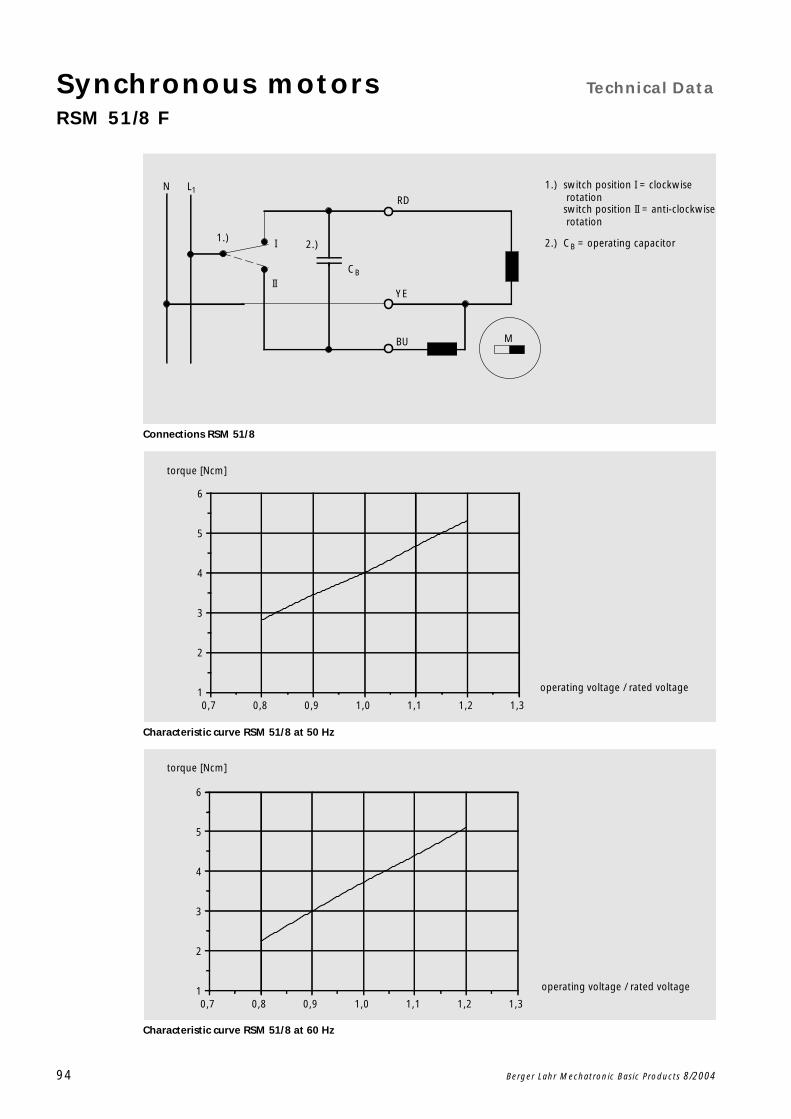
Synchronous motors Technical Data
RSM 51/8 F
94 Berger Lahr Mechatronic Basic Products 8/2004
Connections RSM 51/8
Characteristic curve RSM 51/8 at 50 Hz
Characteristic curve RSM 51/8 at 60 Hz
2.)1.) 2.)
1.)N L1
I
IICB
RD
BU M
YE
switch position I = clockwise rotationswitch position II = anti-clockwise rotation
CB = operating capacitor
0,7 0,8 0,9 1,0 1,1 1,2 1,31
2
3
4
5
6
torque [Ncm]
operating voltage / rated voltage
0,7 0,8 0,9 1,0 1,1 1,2 1,31
2
3
4
5
6
torque [Ncm]
operating voltage / rated voltage

Technical Data Synchronous motorsRSM 51/12 F
Berger Lahr Mechatronic Basic Products 8/2004 95
Scale drawing RSM 51/12
Technical Data
Voltages
Gearbox combinations
You will find gearbox combinations from page 113.
Frequency
50 Hz 60 Hz
Speed 250 rpm 300 rpm
Synchronous torque 5 Ncm 4.4 Ncm
Delivery of power 1.3 W 1.4 W
Power consumption 3.7 W 3.6 W
Rated current (230 V) 16 mA 15.6 mA
Operating capacitor 0.12 F 0.1 F
Maximum externally permitted mass moment of inertia
120 gcm2 80 gcm2
Self-holding torque, type 0.75 Ncm 0.75 Ncm
Excess winding temperature 48 K 46 K
Permitted radial stress Fq 5 N 5 N
Permitted axial stress Fa 2 N 2 N
Weight 0.2 kg 0.2 kg
Protection grade IP 41 to DIN EN 60529 IP 41
Insulation class E to DIN EN 60034-1 E
Dielectric strength Momentary test, test voltage to DIN EN 60034-1
Rated voltage 110 V 42 V 24 V
Frequency 50 Hz 60 Hz 50 Hz 60 Hz 50 Hz 60 Hz
Operating capacitor 0.5 F 0.43 F 3.9 F 3.3 F 10 F 8.2 F
Rated current 33 mA 32 mA 90 mA 87 mA 150 mA 145 mA
= =
R0,5
200±
15
8±2
22
1
ø 3.
4±0.
1
2
R4
14
60±0,1
12±0.5 3 max.
ø 3
h6
ø 11
h6
ø 50
262
UL-Style 1007
flying leads AWG 26: 7x0,16tin-plated
Fq
0.2 to 0.8at Fa > 1,5N:axial travel of spring
Fa
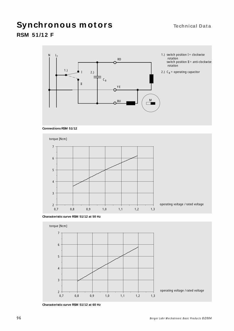
Synchronous motors Technical Data
RSM 51/12 F
96 Berger Lahr Mechatronic Basic Products 8/2004
Connections RSM 51/12
Characteristic curve RSM 51/12 at 50 Hz
Characteristic curve RSM 51/12 at 60 Hz
2.)1.) 2.)
1.)N L1
I
IICB
RD
BU M
YE
switch position I = clockwise rotationswitch position II = anti-clockwise rotation
CB = operating capacitor
1,3
torque [Ncm]
operating voltage / rated voltage
0,7 0,8 0,9 1,0 1,1 1,22
3
4
5
6
7
1,3
torque [Ncm]
operating voltage / rated voltage
0,7 0,8 0,9 1,0 1,1 1,22
3
4
5
6
7
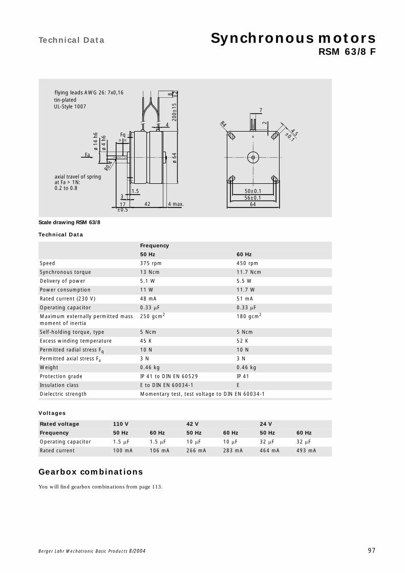
Technical Data Synchronous motorsRSM 63/8 F
Berger Lahr Mechatronic Basic Products 8/2004 97
Scale drawing RSM 63/8
Technical Data
Voltages
Gearbox combinations
You will find gearbox combinations from page 113.
Frequency
50 Hz 60 Hz
Speed 375 rpm 450 rpm
Synchronous torque 13 Ncm 11.7 Ncm
Delivery of power 5.1 W 5.5 W
Power consumption 11 W 11.7 W
Rated current (230 V) 48 mA 51 mA
Operating capacitor 0.33 F 0.33 F
Maximum externally permitted mass moment of inertia
250 gcm2 180 gcm2
Self-holding torque, type 5 Ncm 5 Ncm
Excess winding temperature 45 K 52 K
Permitted radial stress Fq 10 N 10 N
Permitted axial stress Fa 3 N 3 N
Weight 0.46 kg 0.46 kg
Protection grade IP 41 to DIN EN 60529 IP 41
Insulation class E to DIN EN 60034-1 E
Dielectric strength Momentary test, test voltage to DIN EN 60034-1
Rated voltage 110 V 42 V 24 V
Frequency 50 Hz 60 Hz 50 Hz 60 Hz 50 Hz 60 Hz
Operating capacitor 1.5 F 1.5 F 10 F 10 F 32 F 32 F
Rated current 100 mA 106 mA 266 mA 283 mA 464 mA 493 mA
1.5
4.5±0.1
R0.4
200±
158 ±2
644 max.56±0.150±0.1
2
17±0.5
ø 4
h6
R4
7
3
ø 14
h6
ø 64
4
42
UL-Style 1007
flying leads AWG 26: 7x0,16tin-plated
0.2 to 0.8
Fq==
Fa
at Fa > 1N:axial travel of spring

Synchronous motors Technical Data
RSM 63/8 F
98 Berger Lahr Mechatronic Basic Products 8/2004
Connections RSM 63/8
Characteristic curve RSM 63/8 at 50 Hz
Characteristic curve RSM 63/8 at 60 Hz
2.)1.) 2.)
1.)N L1
I
IICB
RD
BU M
YE
switch position I = clockwise rotationswitch position II = anti-clockwise rotation
CB = operating capacitor
0,7 0,8 0,9 1,0 1,1 1,2 1,35,0
7,5
10,0
12,5
15,0
17,5
20,0
torque [Ncm]
operating voltage / rated voltage
0,7 0,8 0,9 1,0 1,1 1,2 1,35,0
7,5
10,0
12,5
15,0
17,5
20,0
torque [Ncm]
operating voltage / rated voltage

Technical Data Synchronous motorsRSM 63/10 F
Berger Lahr Mechatronic Basic Products 8/2004 99
Scale drawing RSM 63/10
Technical Data
Voltages
Gearbox combinations
You will find gearbox combinations from page 113.
Frequency
50 Hz 60 Hz
Speed 300 rpm 360 rpm
Synchronous torque 13.2 Ncm 10 Ncm
Delivery of power 4.2 W 3.8 W
Power consumption 10.2 W 10 W
Rated current (230 V) 45 mA 44 mA
Operating capacitor 0.33 F 0.33 F
Maximum externally permitted mass moment of inertia
230 gcm2 160 gcm2
Self-holding torque, type 2.1 Ncm 2.1 Ncm
Excess winding temperature 73 K 80 K
Permitted radial stress Fq 10 N 10 N
Permitted axial stress Fa 3 N 3 N
Weight 0.46 kg 0.46 kg
Protection grade IP 41 to DIN EN 60529 IP 41
Insulation class E to DIN EN 60034-1 E
Dielectric strength Momentary test, test voltage to DIN EN 60034-1
Rated voltage 110 V 42 V 24 V
Frequency 50 Hz 60 Hz 50 Hz 60 Hz 50 Hz 60 Hz
Operating capacitor 1.5 F 1.5 F 10 F 10 F 32 F 32 F
Rated current 97.9 mA 95.7 mA 254 mA 248 mA 439 mA 430 mA
1.5
4.5±0.1
R0.4
200±
158 ±2
644 max.56±0.150±0.1
2
17±0.5
ø 4
h6
R4
7
3
ø 14
h6
ø 64
4
42
UL-Style 1007
flying leads AWG 26: 7x0,16tin-plated
0.2 to 0.8
Fq==
Fa
at Fa > 1N:axial travel of spring

Synchronous motors Technical Data
RSM 63/10 F
100 Berger Lahr Mechatronic Basic Products 8/2004
Connections RSM 63/10
Characteristic curve RSM 63/10 at 50 Hz
Characteristic curve RSM 63/10 at 60 Hz
2.)1.) 2.)
1.)N L1
I
IICB
RD
BU M
YE
switch position I = clockwise rotationswitch position II = anti-clockwise rotation
CB = operating capacitor
0,7 0,8 0,9 1,0 1,1 1,2 1,32,5
5,0
7,5
10,0
12,5
15,0
17,5
20,0
torque [Ncm]
operating voltage / rated voltage
0,7 0,8 0,9 1,0 1,1 1,2 1,32,5
5,0
7,5
10,0
12,5
15,0
17,5
20,0
torque [Ncm]
operating voltage / rated voltage
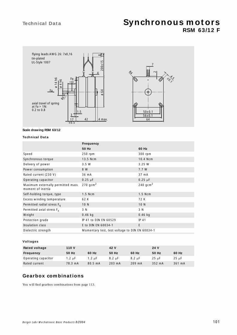
Technical Data Synchronous motorsRSM 63/12 F
Berger Lahr Mechatronic Basic Products 8/2004 101
Scale drawing RSM 63/12
Technical Data
Voltages
Gearbox combinations
You will find gearbox combinations from page 113.
Frequency
50 Hz 60 Hz
Speed 250 rpm 300 rpm
Synchronous torque 13.5 Ncm 10.4 Ncm
Delivery of power 3.5 W 3.25 W
Power consumption 8 W 7.7 W
Rated current (230 V) 36 mA 37 mA
Operating capacitor 0.25 F 0.25 F
Maximum externally permitted mass moment of inertia
270 gcm2 240 gcm2
Self-holding torque, type 1.5 Ncm 1.5 Ncm
Excess winding temperature 62 K 72 K
Permitted radial stress Fq 10 N 10 N
Permitted axial stress Fa 3 N 3 N
Weight 0.46 kg 0.46 kg
Protection grade IP 41 to DIN EN 60529 IP 41
Insulation class E to DIN EN 60034-1 E
Dielectric strength Momentary test, test voltage to DIN EN 60034-1
Rated voltage 110 V 42 V 24 V
Frequency 50 Hz 60 Hz 50 Hz 60 Hz 50 Hz 60 Hz
Operating capacitor 1.2 F 1.2 F 8.2 F 8.2 F 25 F 25 F
Rated current 78.3 mA 80.5 mA 203 mA 209 mA 352 mA 361 mA
1.5
4.5±0.1
R0.4
200±
158 ±2
644 max.56±0.150±0.1
2
17±0.5
ø 4
h6
R4
7
3
ø 14
h6
ø 64
4
42
UL-Style 1007
flying leads AWG 26: 7x0,16tin-plated
0.2 to 0.8
Fq==
Fa
at Fa > 1N:axial travel of spring

Synchronous motors Technical Data
RSM 63/12 F
102 Berger Lahr Mechatronic Basic Products 8/2004
Connections RSM 63/12
Characteristic curve RSM 63/12 at 50 Hz
Characteristic curve RSM 63/12 at 60 Hz
2.)1.) 2.)
1.)N L1
I
IICB
RD
BU M
YE
switch position I = clockwise rotationswitch position II = anti-clockwise rotation
CB = operating capacitor
0,7 0,8 0,9 1,0 1,1 1,2 1,35,0
7,5
10,0
12,5
15,0
17,5
20,0
torque [Ncm]
operating voltage / rated voltage
0,7 0,8 0,9 1,0 1,1 1,2 1,35,0
7,5
10,0
12,5
15,0
17,5
20,0
torque [Ncm]
operating voltage / rated voltage
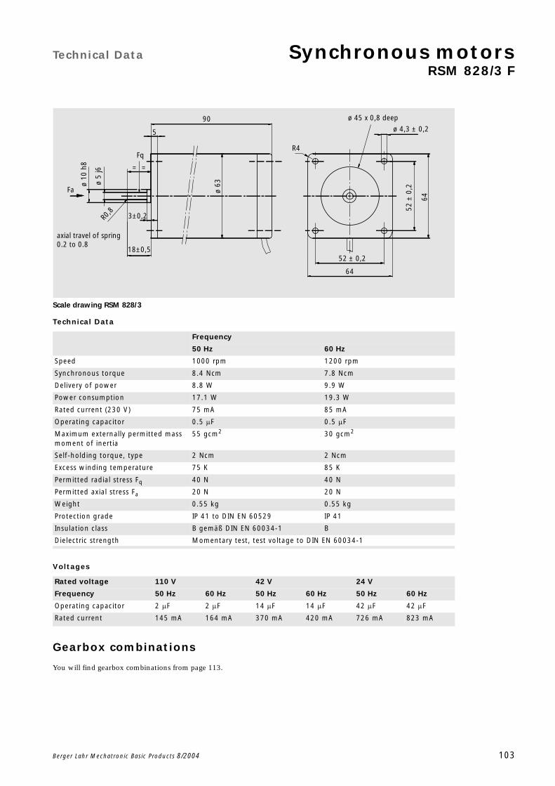
Technical Data Synchronous motorsRSM 828/3 F
Berger Lahr Mechatronic Basic Products 8/2004 103
Scale drawing RSM 828/3
Technical Data
Voltages
Gearbox combinations
You will find gearbox combinations from page 113.
Frequency
50 Hz 60 Hz
Speed 1000 rpm 1200 rpm
Synchronous torque 8.4 Ncm 7.8 Ncm
Delivery of power 8.8 W 9.9 W
Power consumption 17.1 W 19.3 W
Rated current (230 V) 75 mA 85 mA
Operating capacitor 0.5 F 0.5 F
Maximum externally permitted mass moment of inertia
55 gcm2 30 gcm2
Self-holding torque, type 2 Ncm 2 Ncm
Excess winding temperature 75 K 85 K
Permitted radial stress Fq 40 N 40 N
Permitted axial stress Fa 20 N 20 N
Weight 0.55 kg 0.55 kg
Protection grade IP 41 to DIN EN 60529 IP 41
Insulation class B gemäß DIN EN 60034-1 B
Dielectric strength Momentary test, test voltage to DIN EN 60034-1
Rated voltage 110 V 42 V 24 V
Frequency 50 Hz 60 Hz 50 Hz 60 Hz 50 Hz 60 Hz
Operating capacitor 2 F 2 F 14 F 14 F 42 F 42 F
Rated current 145 mA 164 mA 370 mA 420 mA 726 mA 823 mA
90
5
Fq
=
ø 10
h8
ø 5
j6
Fa
axial travel of spring0.2 to 0.8
R0,8 3±0,2
18±0,5
ø 63
R4
ø 45 x 0,8 deep
ø 4,3 ± 0,2
52 ±
0,2
64
52 ± 0,2
64
=
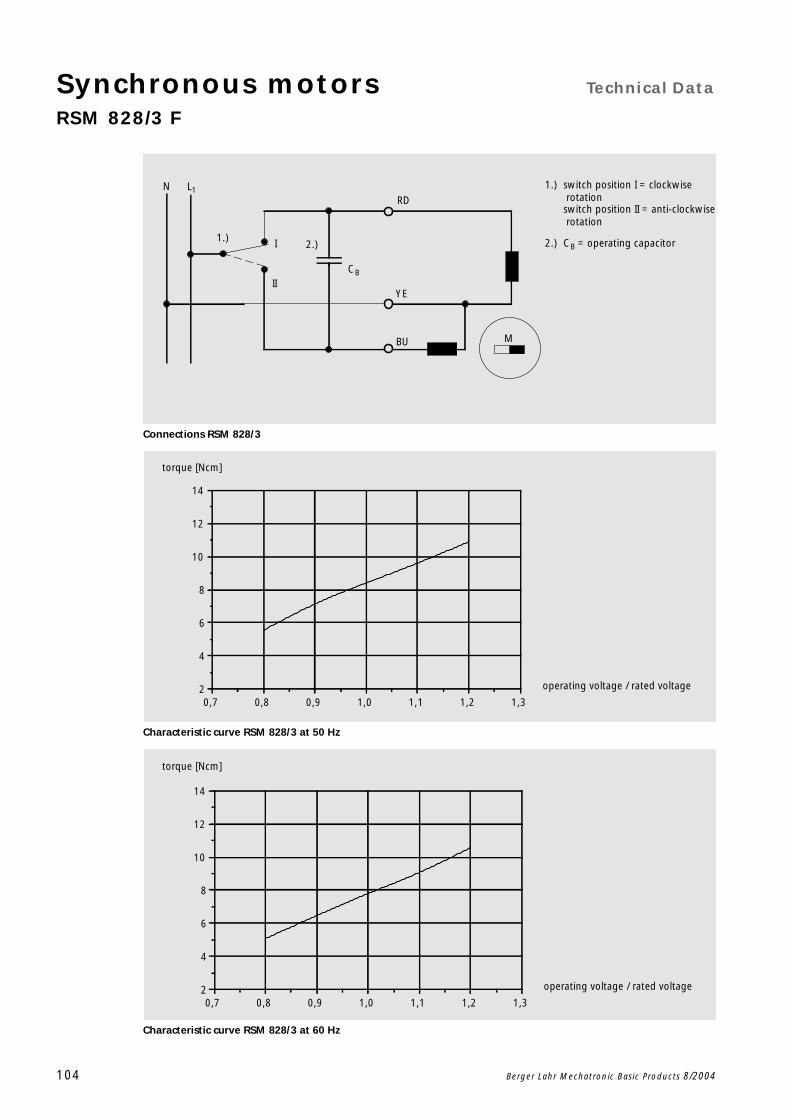
Synchronous motors Technical Data
RSM 828/3 F
104 Berger Lahr Mechatronic Basic Products 8/2004
Connections RSM 828/3
Characteristic curve RSM 828/3 at 50 Hz
Characteristic curve RSM 828/3 at 60 Hz
2.)1.) 2.)
1.)N L1
I
IICB
RD
BU M
YE
switch position I = clockwise rotationswitch position II = anti-clockwise rotation
CB = operating capacitor
0,7 0,8 0,9 1,0 1,1 1,2 1,32
4
6
8
10
12
14
torque [Ncm]
operating voltage / rated voltage
0,7 0,8 0,9 1,0 1,1 1,2 1,32
4
6
8
10
12
14
torque [Ncm]
operating voltage / rated voltage

Technical Data Synchronous motorsRSM 842/3 F
Berger Lahr Mechatronic Basic Products 8/2004 105
Scale drawing RSM 842/3
Technical Data
Voltages
Gearbox combinations
You will find gearbox combinations from page 113.
Frequency
50 Hz 60 Hz
Speed 1000 rpm 1200 rpm
Synchronous torque 9.6 Ncm 9 Ncm
Delivery of power 10.1 W 11.3 W
Power consumption 20.7 W 23.7 W
Rated current (230 V) 92 mA 105 mA
Operating capacitor 0.6 F 0.6 F
Maximum externally permitted mass moment of inertia
80 gcm2 40 gcm2
Self-holding torque, type 3.4 Ncm 3.4 Ncm
Excess winding temperature 85 K 95 K
Permitted radial stress Fq 40 N 40 N
Permitted axial stress Fa 20 N 20 N
Weight 0.75 kg 0.75 kg
Protection grade IP 41 to DIN EN 60529 IP 41
Insulation class B gemäß DIN EN 60034-1 B
Dielectric strength Momentary test, test voltage to DIN EN 60034-1
Rated voltage 110 V 42 V 24 V
Frequency 50 Hz 60 Hz 50 Hz 60 Hz 50 Hz 60 Hz
Operating capacitor 2.5 F 2.5 F 16 F 16 F 48 F 48 F
Rated current 180 mA 206 mA 462 mA 563 mA 828 mA 945 mA
104
5
Fq
=
ø 10
h8
ø 5
j6
Fa
axial travel of spring 0.2 to 0.8
R0,8 3±0,2
18±0,5
ø 63
R4
ø 45 x 0,8 deep
ø 4,3 ± 0,2
52 ±
0,2
64
52 ± 0,2
64
=
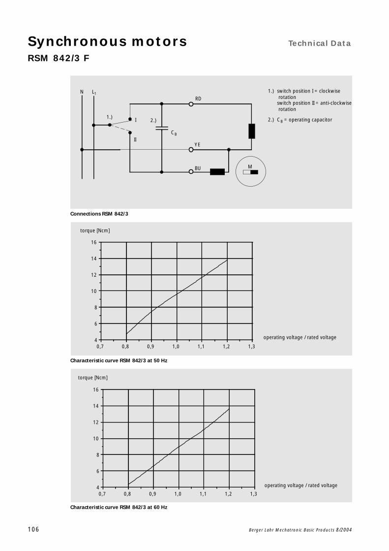
Synchronous motors Technical Data
RSM 842/3 F
106 Berger Lahr Mechatronic Basic Products 8/2004
Connections RSM 842/3
Characteristic curve RSM 842/3 at 50 Hz
Characteristic curve RSM 842/3 at 60 Hz
2.)1.) 2.)
1.)N L1
I
IICB
RD
BU M
YE
switch position I = clockwise rotationswitch position II = anti-clockwise rotation
CB = operating capacitor
0,7 0,8 0,9 1,0 1,1 1,2 1,34
6
8
10
12
14
16
torque [Ncm]
operating voltage / rated voltage
0,7 0,8 0,9 1,0 1,1 1,2 1,34
6
8
10
12
14
16
torque [Ncm]
operating voltage / rated voltage

Technical Data Synchronous motorsRSM 856/3 F
Berger Lahr Mechatronic Basic Products 8/2004 107
Scale drawing RSM 856/3
Technical Data
Voltages
Gearbox combinations
You will find gearbox combinations from page 113.
Frequency
50 Hz 60 Hz
Speed 1000 rpm 1200 rpm
Synchronous torque 13.2 Ncm 12.6 Ncm
Delivery of power 13.9 W 15.8 W
Power consumption 24.6 W 27.6 W
Rated current (230 V) 109 mA 121 mA
Operating capacitor 0.68 F 0.68 F
Maximum externally permitted mass moment of inertia
140 gcm2 65 gcm2
Self-holding torque, type 4.1 Ncm 4.1 Ncm
Excess winding temperature 80 K 85 K
Permitted radial stress Fq 40 N 40 N
Permitted axial stress Fa 20 N 20 N
Weight 0.9 kg 0.9 kg
Protection grade IP 41 to DIN EN 60529 IP 41
Insulation class B gemäß DIN EN 60034-1 B
Dielectric strength Momentary test, test voltage to DIN EN 60034-1
Rated voltage 110 V 42 V 24 V
Frequency 50 Hz 60 Hz 50 Hz 60 Hz 50 Hz 60 Hz
Operating capacitor 2.7 F 2.7 F 18 F 18 F 57 F 57 F
Rated current 214 mA 237 mA 545 mA 607 mA 981 mA 1089 mA
118
5
Fq
=
ø 10
h8
ø 5
j6
Fa
axial travel of spring0.2 to 0.8
R0,8 3±0,2
18±0,5
ø 63
R4
ø 45 x 0,8 deep
ø 4,3 ± 0,2
52 ±
0,2
64
52 ± 0,2
64
=
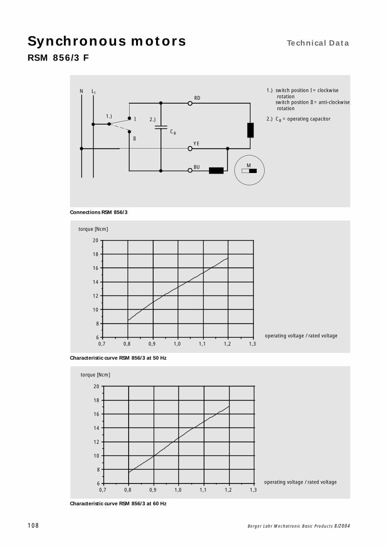
Synchronous motors Technical Data
RSM 856/3 F
108 Berger Lahr Mechatronic Basic Products 8/2004
Connections RSM 856/3
Characteristic curve RSM 856/3 at 50 Hz
Characteristic curve RSM 856/3 at 60 Hz
2.)1.) 2.)
1.)N L1
I
IICB
RD
BU M
YE
switch position I = clockwise rotationswitch position II = anti-clockwise rotation
CB = operating capacitor
0,7 0,8 0,9 1,0 1,1 1,2 1,36
8
10
12
14
16
18
20
torque [Ncm]
operating voltage / rated voltage
0,7 0,8 0,9 1,0 1,1 1,2 1,36
8
10
12
14
16
18
20
torque [Ncm]
operating voltage / rated voltage

Technical Data Synchronous motorsRSM 884/3 F
Berger Lahr Mechatronic Basic Products 8/2004 109
Scale drawing RSM 884/3
Technical Data
Voltages
Gearbox combinations
You will find gearbox combinations from page 113.
Frequency
50 Hz 60 Hz
Speed 1000 rpm 1200 rpm
Synchronous torque 18.1 Ncm 15.3 Ncm
Delivery of power 18.9 W 19.2 W
Power consumption 30.1 W 33.7 W
Rated current (230 V) 134 mA 149 mA
Operating capacitor 0.82 F 0.82 F
Maximum externally permitted mass moment of inertia
150 gcm2 70 gcm2
Self-holding torque, type 6 Ncm 6 Ncm
Excess winding temperature 70 K 80 K
Permitted radial stress Fq 40 N 40 N
Permitted axial stress Fa 20 N 20 N
Weight 1.25 kg 1.25 kg
Protection grade IP 41 to DIN EN 60529 IP 41
Insulation class B gemäß DIN EN 60034-1 B
Dielectric strength Momentary test, test voltage to DIN EN 60034-1
Rated voltage 110 V 42 V 24 V
Frequency 50 Hz 60 Hz 50 Hz 60 Hz 50 Hz 60 Hz
Operating capacitor 3.3 F 3.3 F 27 F 27 F 70 F 70 F
Rated current 278 mA 309 mA 763 mA 849 mA 1231 mA 1368 mA
146
5
Fq
=
ø 10
h8
ø 5
j6
Fa
axial travel of spring 0.2 to 0.8
R0,8 3±0,2
18±0,5
ø 63
R4
ø 45 x 0,8 deep
ø 4,3 ± 0,2
52 ±
0,2
64
52 ± 0,2
64
=

Synchronous motors Technical Data
RSM 884/3 F
110 Berger Lahr Mechatronic Basic Products 8/2004
Connections RSM 884/3
Characteristic curve RSM 884/3 at 50 Hz
Characteristic curve RSM 884/3 at 60 Hz
2.)1.) 2.)
1.)N L1
I
IICB
RD
BU M
YE
switch position I = clockwise rotationswitch position II = anti-clockwise rotation
CB = operating capacitor
0,7 0,8 0,9 1,0 1,1 1,2 1,36
10
14
18
22
26
torque [Ncm]
operating voltage / rated voltage
0,7 0,8 0,9 1,0 1,1 1,2 1,36
10
14
18
22
26
torque [Ncm]
operating voltage / rated voltage
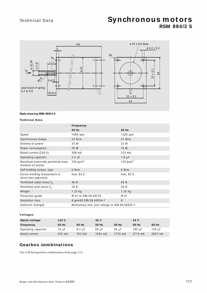
Technical Data Synchronous motorsRSM 884/3 S
Berger Lahr Mechatronic Basic Products 8/2004 111
Scale drawing RSM 884/3 S
Technical Data
Voltages
Gearbox combinations
You will find gearbox combinations from page 113.
Frequency
50 Hz 60 Hz
Speed 1000 rpm 1200 rpm
Synchronous torque 33 Ncm 31 Ncm
Delivery of power 35 W 32 W
Power consumption 70 W 74 W
Rated current (230 V) 308 mA 323 mA
Operating capacitor 2.2 F 1.8 F
Maximum externally permitted mass moment of inertia
250 gcm2 150 gcm2
Self-holding torque, type 6 Ncm 6 Ncm
Excess winding temperature in short-time operation
max. 85 K max. 85 K
Permitted radial stress Fq 40 N 40 N
Permitted axial stress Fa 20 N 20 N
Weight 1.25 kg 1.25 kg
Protection grade IP 41 to DIN EN 60529 IP 41
Insulation class B gemäß DIN EN 60034-1 B
Dielectric strength Momentary test, test voltage to DIN EN 60034-1
Rated voltage 110 V 42 V 24 V
Frequency 50 Hz 60 Hz 50 Hz 60 Hz 50 Hz 60 Hz
Operating capacitor 10 F 8.2 F 68 F 56 F 180 F 150 F
Rated current 670 mA 703 mA 1692 mA 1774 mA 2715 mA 2847 mA
146
5
Fq
=
ø 10
h8
ø 5
j6
Fa
axial travel of spring 0.2 to 0.8
R0,8 3±0,2
18±0,5
ø 63
R4
ø 45 x 0,8 deep
ø 4,3 ± 0,2
52 ±
0,2
64
52 ± 0,2
64
=
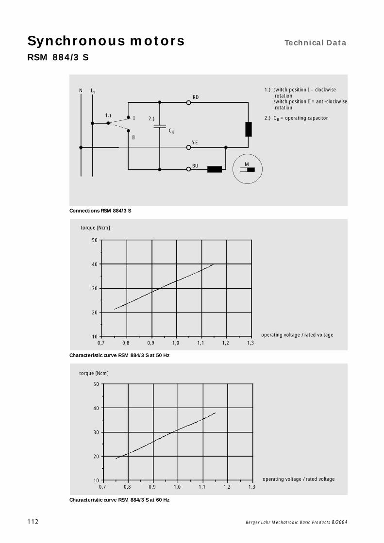
Synchronous motors Technical Data
RSM 884/3 S
112 Berger Lahr Mechatronic Basic Products 8/2004
Connections RSM 884/3 S
Characteristic curve RSM 884/3 S at 50 Hz
Characteristic curve RSM 884/3 S at 60 Hz
2.)1.) 2.)
1.)N L1
I
IICB
RD
BU M
YE
switch position I = clockwise rotationswitch position II = anti-clockwise rotation
CB = operating capacitor
0,7 0,8 0,9 1,0 1,1 1,2 1,310
20
30
40
50
torque [Ncm]
operating voltage / rated voltage
0,7 0,8 0,9 1,0 1,1 1,2 1,310
20
30
40
50
torque [Ncm]
operating voltage / rated voltage

Options Synchronous motorswith geared motors
Berger Lahr Mechatronic Basic Products 8/2004 113
Motor-/ Gearbox combination Synchronous motors (RSM)
Motor type RSM
Gearbox type
L T G P
36/8
36/10
42/8
51/8
63/8
63/10
828
842
856
884
884 S
Synchronous motors
114 Berger Lahr Mechatronic Basic Products 8/2004
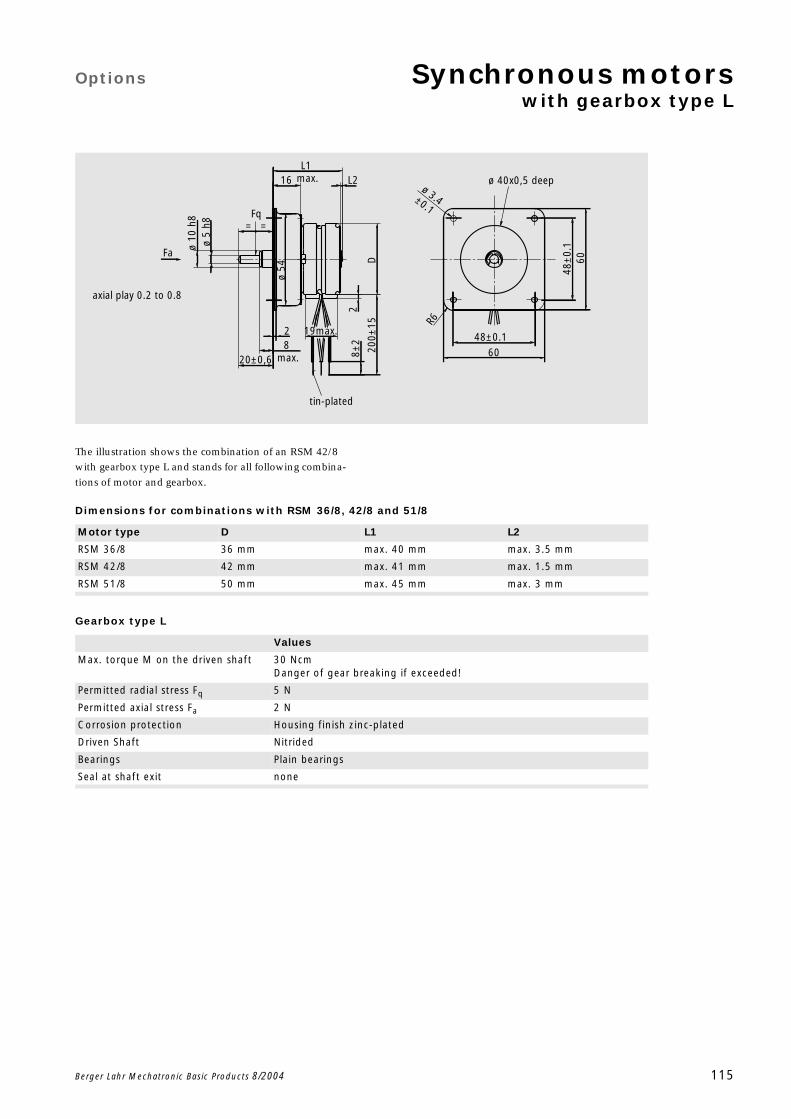
Options Synchronous motorswith gearbox type L
Berger Lahr Mechatronic Basic Products 8/2004 115
The illustration shows the combination of an RSM 42/8
with gearbox type L and stands for all following combina-
tions of motor and gearbox.
Dimensions for combinations with RSM 36/8, 42/8 and 51/8
Gearbox type L
tin-plated
axial play 0.2 to 0.8
ø 40x0,5 deep
==Fq
Fa
L2
200±
15
8±2
6048
±0.
1
ø 3.4±0.1
R6
48±0.160
2
D
16
ø 54
L1 max.
ø 5
h8ø
10 h
8
19max.
20±0,68
max.
2
Motor type D L1 L2
RSM 36/8 36 mm max. 40 mm max. 3.5 mm
RSM 42/8 42 mm max. 41 mm max. 1.5 mm
RSM 51/8 50 mm max. 45 mm max. 3 mm
Values
Max. torque M on the driven shaft 30 NcmDanger of gear breaking if exceeded!
Permitted radial stress Fq 5 N
Permitted axial stress Fa 2 N
Corrosion protection Housing finish zinc-plated
Driven Shaft Nitrided
Bearings Plain bearings
Seal at shaft exit none
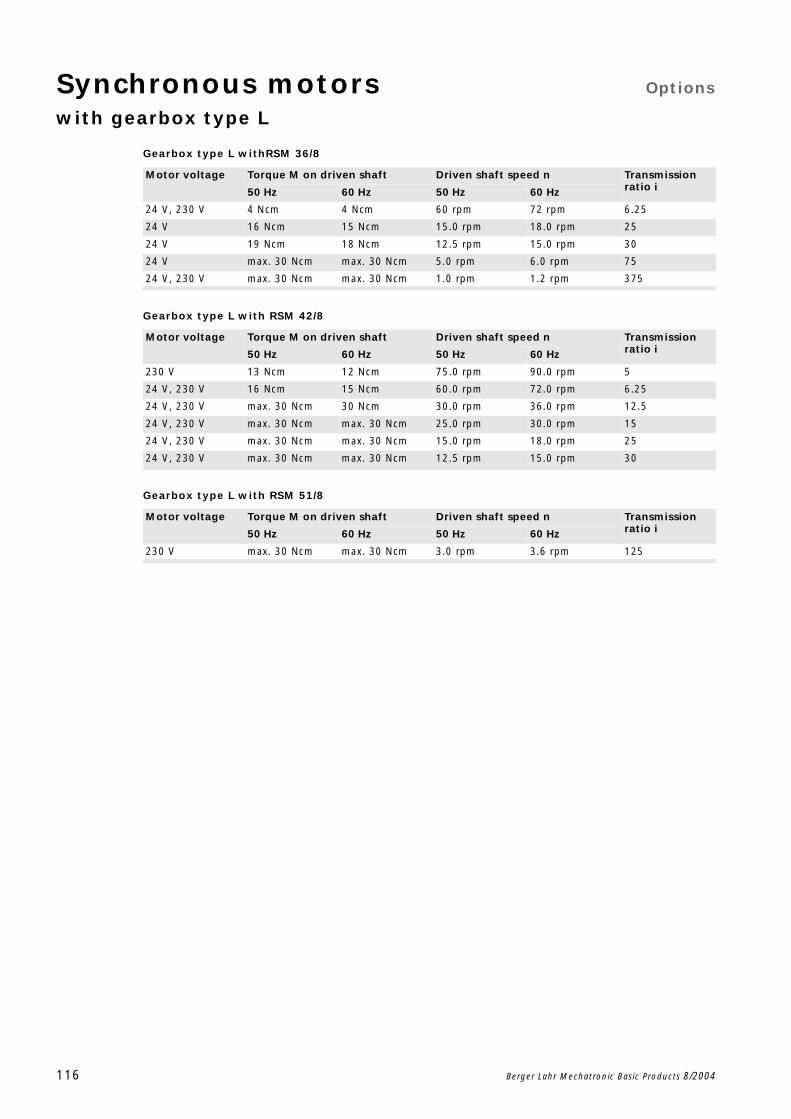
Synchronous motors Options
with gearbox type L
116 Berger Lahr Mechatronic Basic Products 8/2004
Gearbox type L withRSM 36/8
Gearbox type L with RSM 42/8
Gearbox type L with RSM 51/8
Motor voltage Torque M on driven shaft Driven shaft speed n Transmission ratio i50 Hz 60 Hz 50 Hz 60 Hz
24 V, 230 V 4 Ncm 4 Ncm 60 rpm 72 rpm 6.25
24 V 16 Ncm 15 Ncm 15.0 rpm 18.0 rpm 25
24 V 19 Ncm 18 Ncm 12.5 rpm 15.0 rpm 30
24 V max. 30 Ncm max. 30 Ncm 5.0 rpm 6.0 rpm 75
24 V, 230 V max. 30 Ncm max. 30 Ncm 1.0 rpm 1.2 rpm 375
Motor voltage Torque M on driven shaft Driven shaft speed n Transmission ratio i50 Hz 60 Hz 50 Hz 60 Hz
230 V 13 Ncm 12 Ncm 75.0 rpm 90.0 rpm 5
24 V, 230 V 16 Ncm 15 Ncm 60.0 rpm 72.0 rpm 6.25
24 V, 230 V max. 30 Ncm 30 Ncm 30.0 rpm 36.0 rpm 12.5
24 V, 230 V max. 30 Ncm max. 30 Ncm 25.0 rpm 30.0 rpm 15
24 V, 230 V max. 30 Ncm max. 30 Ncm 15.0 rpm 18.0 rpm 25
24 V, 230 V max. 30 Ncm max. 30 Ncm 12.5 rpm 15.0 rpm 30
Motor voltage Torque M on driven shaft Driven shaft speed n Transmission ratio i50 Hz 60 Hz 50 Hz 60 Hz
230 V max. 30 Ncm max. 30 Ncm 3.0 rpm 3.6 rpm 125
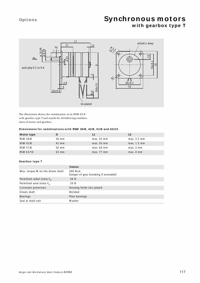
Options Synchronous motorswith gearbox type T
Berger Lahr Mechatronic Basic Products 8/2004 117
The illustration shows the combination of an RSM 63/8
with gearbox type T and stands for all following combina-
tions of motor and gearbox.
Dimensions for combinations with RSM 36/8, 42/8, 51/8 and 63/10
Gearbox type T
tin-plated
axial play 0.2 to 0.8
14
200±
15
8±2
2
L1
31 L2
D
R7
ø 5.3±0.1
7056±0.2
7056
±0.
2ø 63
14
26±0.8
4
2.8
ø 14
h8
ø 8
h8
Fa
Fq==
ø56x0,5 deep
Motor type D L1 L2
RSM 36/8 36 mm max. 55 mm max. 3.5 mm
RSM 42/8 42 mm max. 56 mm max. 1.5 mm
RSM 51/8 50 mm max. 60 mm max. 3 mm
RSM 63/10 63 mm max. 77 mm max. 4 mm
Values
Max. torque M on the driven shaft 300 NcmDanger of gear breaking if exceeded!
Permitted radial stress Fq 30 N
Permitted axial stress Fa 20 N
Corrosion protection Housing finish zinc-plated
Driven shaft Nitrided
Bearings Plain bearings
Seal at shaft exit Washer
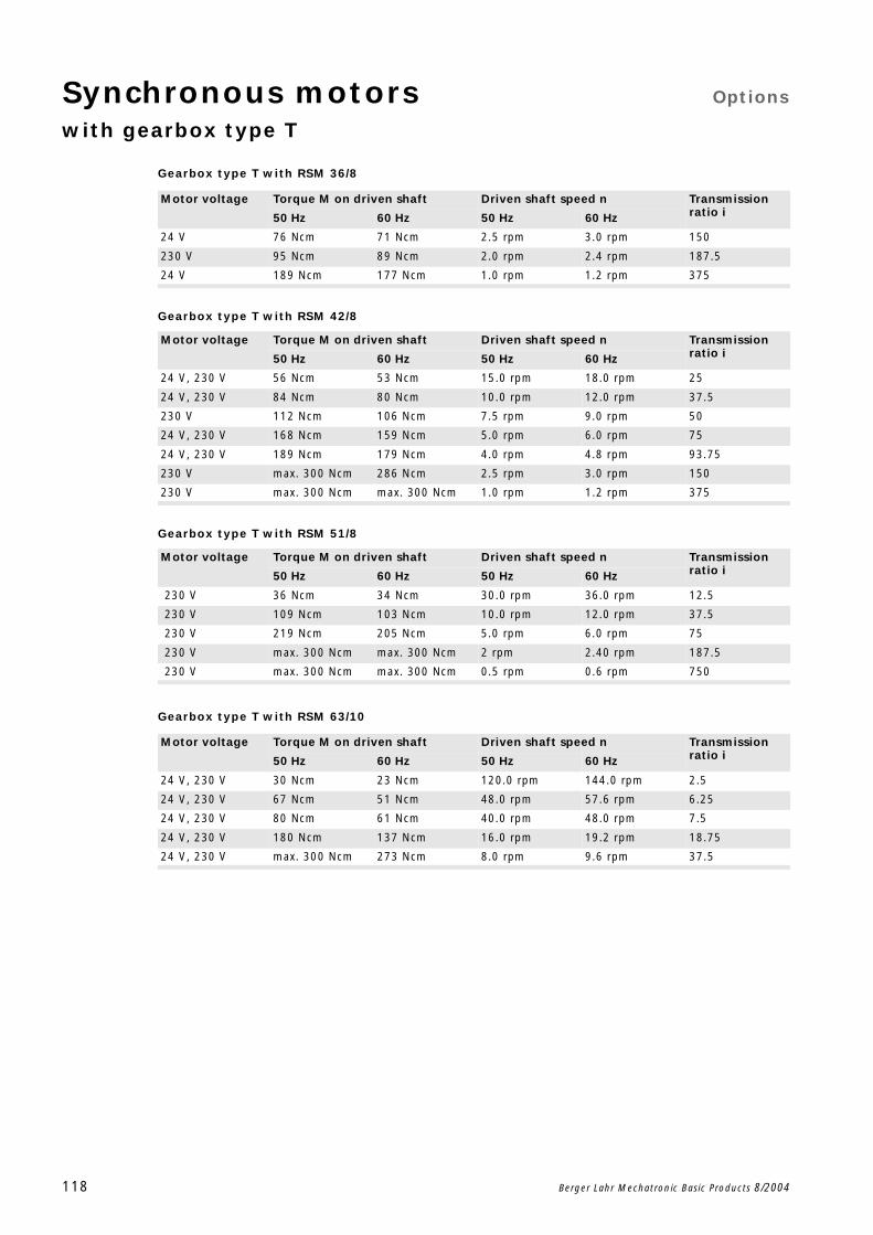
Synchronous motors Options
with gearbox type T
118 Berger Lahr Mechatronic Basic Products 8/2004
Gearbox type T with RSM 36/8
Gearbox type T with RSM 42/8
Gearbox type T with RSM 51/8
Gearbox type T with RSM 63/10
Motor voltage Torque M on driven shaft Driven shaft speed n Transmission ratio i50 Hz 60 Hz 50 Hz 60 Hz
24 V 76 Ncm 71 Ncm 2.5 rpm 3.0 rpm 150
230 V 95 Ncm 89 Ncm 2.0 rpm 2.4 rpm 187.5
24 V 189 Ncm 177 Ncm 1.0 rpm 1.2 rpm 375
Motor voltage Torque M on driven shaft Driven shaft speed n Transmission ratio i50 Hz 60 Hz 50 Hz 60 Hz
24 V, 230 V 56 Ncm 53 Ncm 15.0 rpm 18.0 rpm 25
24 V, 230 V 84 Ncm 80 Ncm 10.0 rpm 12.0 rpm 37.5
230 V 112 Ncm 106 Ncm 7.5 rpm 9.0 rpm 50
24 V, 230 V 168 Ncm 159 Ncm 5.0 rpm 6.0 rpm 75
24 V, 230 V 189 Ncm 179 Ncm 4.0 rpm 4.8 rpm 93.75
230 V max. 300 Ncm 286 Ncm 2.5 rpm 3.0 rpm 150
230 V max. 300 Ncm max. 300 Ncm 1.0 rpm 1.2 rpm 375
Motor voltage Torque M on driven shaft Driven shaft speed n Transmission ratio i50 Hz 60 Hz 50 Hz 60 Hz
230 V 36 Ncm 34 Ncm 30.0 rpm 36.0 rpm 12.5
230 V 109 Ncm 103 Ncm 10.0 rpm 12.0 rpm 37.5
230 V 219 Ncm 205 Ncm 5.0 rpm 6.0 rpm 75
230 V max. 300 Ncm max. 300 Ncm 2 rpm 2.40 rpm 187.5
230 V max. 300 Ncm max. 300 Ncm 0.5 rpm 0.6 rpm 750
Motor voltage Torque M on driven shaft Driven shaft speed n Transmission ratio i50 Hz 60 Hz 50 Hz 60 Hz
24 V, 230 V 30 Ncm 23 Ncm 120.0 rpm 144.0 rpm 2.5
24 V, 230 V 67 Ncm 51 Ncm 48.0 rpm 57.6 rpm 6.25
24 V, 230 V 80 Ncm 61 Ncm 40.0 rpm 48.0 rpm 7.5
24 V, 230 V 180 Ncm 137 Ncm 16.0 rpm 19.2 rpm 18.75
24 V, 230 V max. 300 Ncm 273 Ncm 8.0 rpm 9.6 rpm 37.5
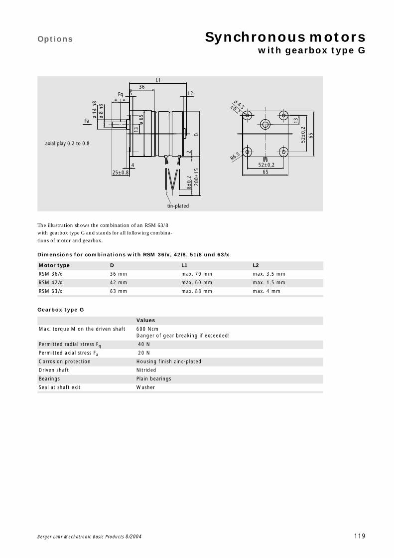
Options Synchronous motorswith gearbox type G
Berger Lahr Mechatronic Basic Products 8/2004 119
The illustration shows the combination of an RSM 63/8
with gearbox type G and stands for all following combina-
tions of motor and gearbox.
Dimensions for combinations with RSM 36/x, 42/8, 51/8 und 63/x
Gearbox type G
tin-plated
axial play 0.2 to 0.8
ø 4.3±0.2
=
L1
200±
158±
0.2
2
L2
D
R6.5
1352
±0,
2
65
6552±0,2
Fq
ø 65
13
=
Fa
ø 14
h8
ø 8
h85
36
25±0.84
Motor type D L1 L2
RSM 36/x 36 mm max. 70 mm max. 3.5 mm
RSM 42/x 42 mm max. 60 mm max. 1.5 mm
RSM 63/x 63 mm max. 88 mm max. 4 mm
Values
Max. torque M on the driven shaft 600 NcmDanger of gear breaking if exceeded!
Permitted radial stress Fq 40 N
Permitted axial stress Fa 20 N
Corrosion protection Housing finish zinc-plated
Driven shaft Nitrided
Bearings Plain bearings
Seal at shaft exit Washer
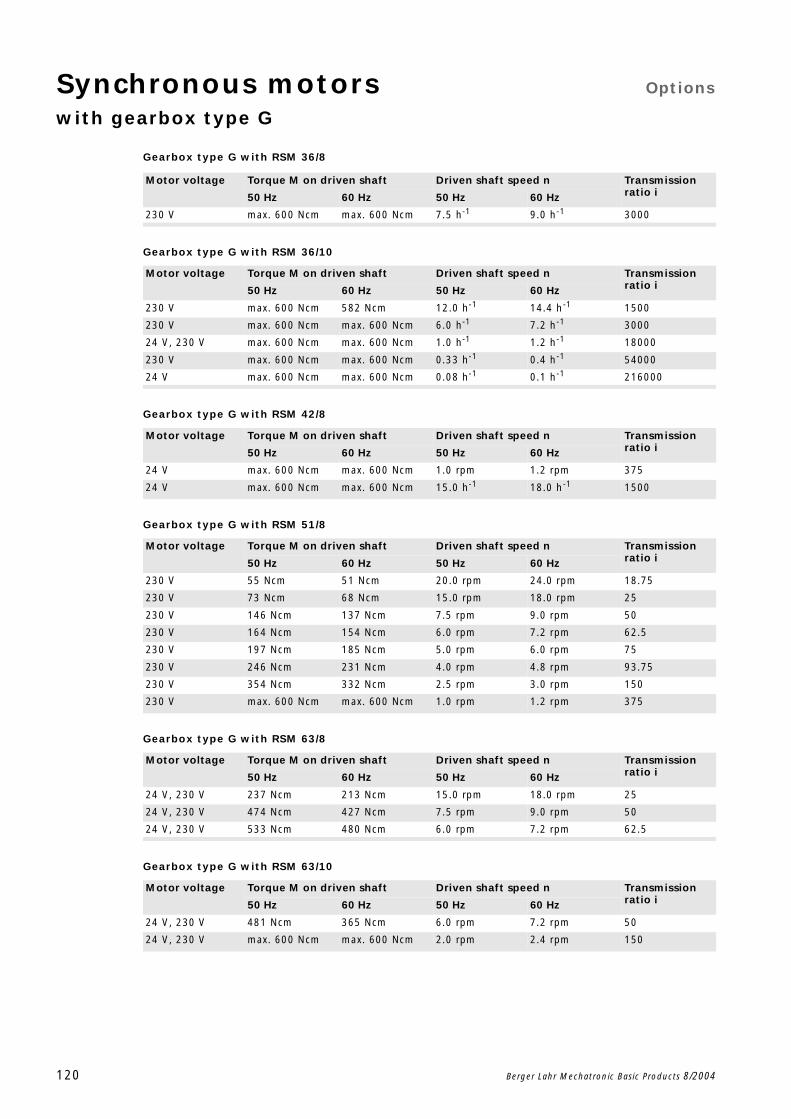
Synchronous motors Options
with gearbox type G
120 Berger Lahr Mechatronic Basic Products 8/2004
Gearbox type G with RSM 36/8
Gearbox type G with RSM 36/10
Gearbox type G with RSM 42/8
Gearbox type G with RSM 51/8
Gearbox type G with RSM 63/8
Gearbox type G with RSM 63/10
Motor voltage Torque M on driven shaft Driven shaft speed n Transmission ratio i50 Hz 60 Hz 50 Hz 60 Hz
230 V max. 600 Ncm max. 600 Ncm 7.5 h-1 9.0 h-1 3000
Motor voltage Torque M on driven shaft Driven shaft speed n Transmission ratio i50 Hz 60 Hz 50 Hz 60 Hz
230 V max. 600 Ncm 582 Ncm 12.0 h-1 14.4 h-1 1500
230 V max. 600 Ncm max. 600 Ncm 6.0 h-1 7.2 h-1 3000
24 V, 230 V max. 600 Ncm max. 600 Ncm 1.0 h-1 1.2 h-1 18000
230 V max. 600 Ncm max. 600 Ncm 0.33 h-1 0.4 h-1 54000
24 V max. 600 Ncm max. 600 Ncm 0.08 h-1 0.1 h-1 216000
Motor voltage Torque M on driven shaft Driven shaft speed n Transmission ratio i50 Hz 60 Hz 50 Hz 60 Hz
24 V max. 600 Ncm max. 600 Ncm 1.0 rpm 1.2 rpm 375
24 V max. 600 Ncm max. 600 Ncm 15.0 h-1 18.0 h-1 1500
Motor voltage Torque M on driven shaft Driven shaft speed n Transmission ratio i50 Hz 60 Hz 50 Hz 60 Hz
230 V 55 Ncm 51 Ncm 20.0 rpm 24.0 rpm 18.75
230 V 73 Ncm 68 Ncm 15.0 rpm 18.0 rpm 25
230 V 146 Ncm 137 Ncm 7.5 rpm 9.0 rpm 50
230 V 164 Ncm 154 Ncm 6.0 rpm 7.2 rpm 62.5
230 V 197 Ncm 185 Ncm 5.0 rpm 6.0 rpm 75
230 V 246 Ncm 231 Ncm 4.0 rpm 4.8 rpm 93.75
230 V 354 Ncm 332 Ncm 2.5 rpm 3.0 rpm 150
230 V max. 600 Ncm max. 600 Ncm 1.0 rpm 1.2 rpm 375
Motor voltage Torque M on driven shaft Driven shaft speed n Transmission ratio i50 Hz 60 Hz 50 Hz 60 Hz
24 V, 230 V 237 Ncm 213 Ncm 15.0 rpm 18.0 rpm 25
24 V, 230 V 474 Ncm 427 Ncm 7.5 rpm 9.0 rpm 50
24 V, 230 V 533 Ncm 480 Ncm 6.0 rpm 7.2 rpm 62.5
Motor voltage Torque M on driven shaft Driven shaft speed n Transmission ratio i50 Hz 60 Hz 50 Hz 60 Hz
24 V, 230 V 481 Ncm 365 Ncm 6.0 rpm 7.2 rpm 50
24 V, 230 V max. 600 Ncm max. 600 Ncm 2.0 rpm 2.4 rpm 150
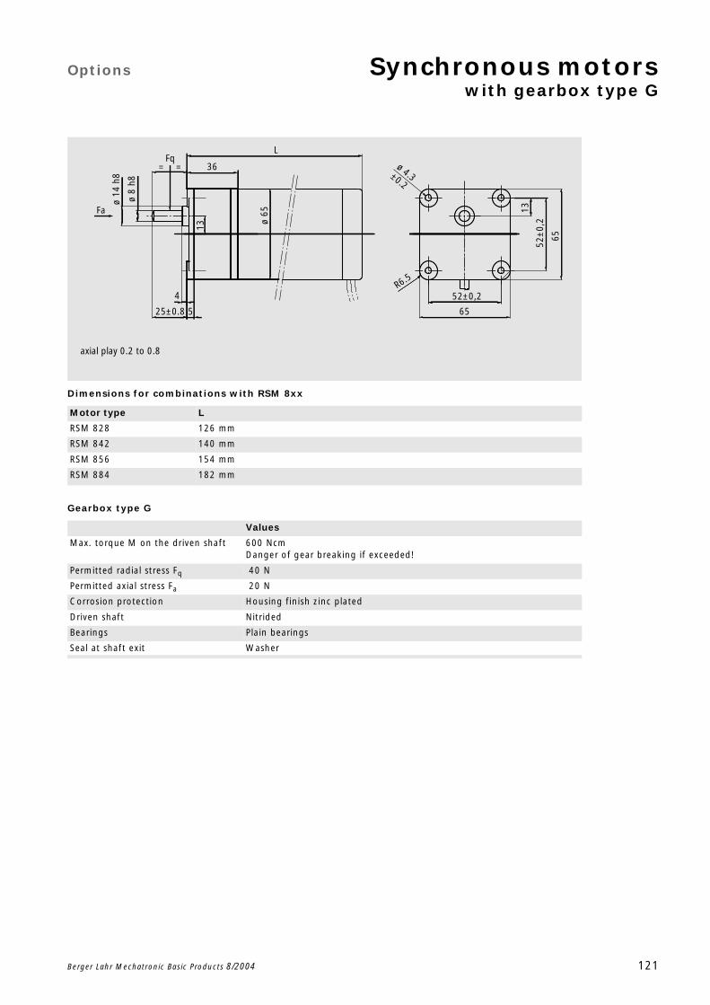
Options Synchronous motorswith gearbox type G
Berger Lahr Mechatronic Basic Products 8/2004 121
Dimensions for combinations with RSM 8xx
Gearbox type G
Motor type L
RSM 828 126 mm
RSM 842 140 mm
RSM 856 154 mm
RSM 884 182 mm
Values
Max. torque M on the driven shaft 600 NcmDanger of gear breaking if exceeded!
Permitted radial stress Fq 40 N
Permitted axial stress Fa 20 N
Corrosion protection Housing finish zinc plated
Driven shaft Nitrided
Bearings Plain bearings
Seal at shaft exit Washer
axial play 0.2 to 0.8
= =
13
5
L
36 ø 4.3±0.2
R6.5
52±0,2
52±
0,2
65
ø 65
4
ø 14
h8
ø 8
h8
13
6525±0.8
Fa
Fq
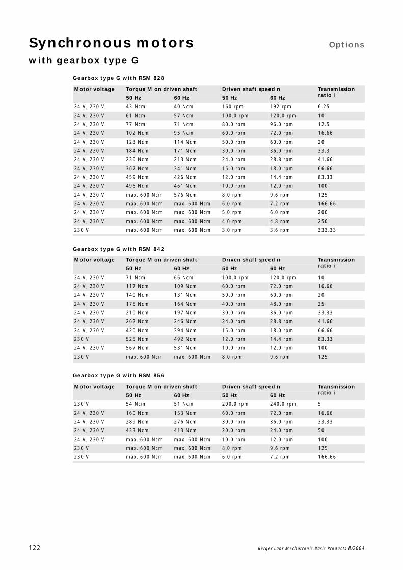
Synchronous motors Options
with gearbox type G
122 Berger Lahr Mechatronic Basic Products 8/2004
Gearbox type G with RSM 828
Gearbox type G with RSM 842
Gearbox type G with RSM 856
Motor voltage Torque M on driven shaft Driven shaft speed n Transmission ratio i50 Hz 60 Hz 50 Hz 60 Hz
24 V, 230 V 43 Ncm 40 Ncm 160 rpm 192 rpm 6.25
24 V, 230 V 61 Ncm 57 Ncm 100.0 rpm 120.0 rpm 10
24 V, 230 V 77 Ncm 71 Ncm 80.0 rpm 96.0 rpm 12.5
24 V, 230 V 102 Ncm 95 Ncm 60.0 rpm 72.0 rpm 16.66
24 V, 230 V 123 Ncm 114 Ncm 50.0 rpm 60.0 rpm 20
24 V, 230 V 184 Ncm 171 Ncm 30.0 rpm 36.0 rpm 33.3
24 V, 230 V 230 Ncm 213 Ncm 24.0 rpm 28.8 rpm 41.66
24 V, 230 V 367 Ncm 341 Ncm 15.0 rpm 18.0 rpm 66.66
24 V, 230 V 459 Ncm 426 Ncm 12.0 rpm 14.4 rpm 83.33
24 V, 230 V 496 Ncm 461 Ncm 10.0 rpm 12.0 rpm 100
24 V, 230 V max. 600 Ncm 576 Ncm 8.0 rpm 9.6 rpm 125
24 V, 230 V max. 600 Ncm max. 600 Ncm 6.0 rpm 7.2 rpm 166.66
24 V, 230 V max. 600 Ncm max. 600 Ncm 5.0 rpm 6.0 rpm 200
24 V, 230 V max. 600 Ncm max. 600 Ncm 4.0 rpm 4.8 rpm 250
230 V max. 600 Ncm max. 600 Ncm 3.0 rpm 3.6 rpm 333.33
Motor voltage Torque M on driven shaft Driven shaft speed n Transmission ratio i50 Hz 60 Hz 50 Hz 60 Hz
24 V, 230 V 71 Ncm 66 Ncm 100.0 rpm 120.0 rpm 10
24 V, 230 V 117 Ncm 109 Ncm 60.0 rpm 72.0 rpm 16.66
24 V, 230 V 140 Ncm 131 Ncm 50.0 rpm 60.0 rpm 20
24 V, 230 V 175 Ncm 164 Ncm 40.0 rpm 48.0 rpm 25
24 V, 230 V 210 Ncm 197 Ncm 30.0 rpm 36.0 rpm 33.33
24 V, 230 V 262 Ncm 246 Ncm 24.0 rpm 28.8 rpm 41.66
24 V, 230 V 420 Ncm 394 Ncm 15.0 rpm 18.0 rpm 66.66
230 V 525 Ncm 492 Ncm 12.0 rpm 14.4 rpm 83.33
24 V, 230 V 567 Ncm 531 Ncm 10.0 rpm 12.0 rpm 100
230 V max. 600 Ncm max. 600 Ncm 8.0 rpm 9.6 rpm 125
Motor voltage Torque M on driven shaft Driven shaft speed n Transmission ratio i50 Hz 60 Hz 50 Hz 60 Hz
230 V 54 Ncm 51 Ncm 200.0 rpm 240.0 rpm 5
24 V, 230 V 160 Ncm 153 Ncm 60.0 rpm 72.0 rpm 16.66
24 V, 230 V 289 Ncm 276 Ncm 30.0 rpm 36.0 rpm 33.33
24 V, 230 V 433 Ncm 413 Ncm 20.0 rpm 24.0 rpm 50
24 V, 230 V max. 600 Ncm max. 600 Ncm 10.0 rpm 12.0 rpm 100
230 V max. 600 Ncm max. 600 Ncm 8.0 rpm 9.6 rpm 125
230 V max. 600 Ncm max. 600 Ncm 6.0 rpm 7.2 rpm 166.66
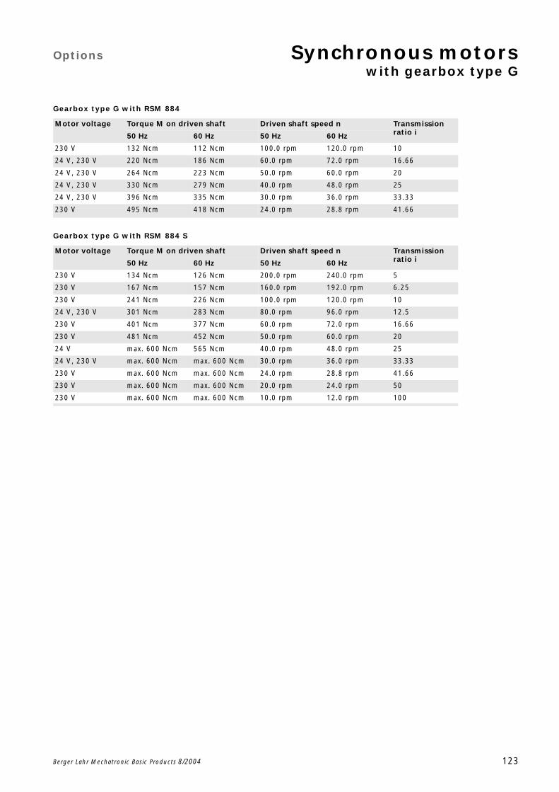
Options Synchronous motorswith gearbox type G
Berger Lahr Mechatronic Basic Products 8/2004 123
Gearbox type G with RSM 884
Gearbox type G with RSM 884 S
Motor voltage Torque M on driven shaft Driven shaft speed n Transmission ratio i50 Hz 60 Hz 50 Hz 60 Hz
230 V 132 Ncm 112 Ncm 100.0 rpm 120.0 rpm 10
24 V, 230 V 220 Ncm 186 Ncm 60.0 rpm 72.0 rpm 16.66
24 V, 230 V 264 Ncm 223 Ncm 50.0 rpm 60.0 rpm 20
24 V, 230 V 330 Ncm 279 Ncm 40.0 rpm 48.0 rpm 25
24 V, 230 V 396 Ncm 335 Ncm 30.0 rpm 36.0 rpm 33.33
230 V 495 Ncm 418 Ncm 24.0 rpm 28.8 rpm 41.66
Motor voltage Torque M on driven shaft Driven shaft speed n Transmission ratio i50 Hz 60 Hz 50 Hz 60 Hz
230 V 134 Ncm 126 Ncm 200.0 rpm 240.0 rpm 5
230 V 167 Ncm 157 Ncm 160.0 rpm 192.0 rpm 6.25
230 V 241 Ncm 226 Ncm 100.0 rpm 120.0 rpm 10
24 V, 230 V 301 Ncm 283 Ncm 80.0 rpm 96.0 rpm 12.5
230 V 401 Ncm 377 Ncm 60.0 rpm 72.0 rpm 16.66
230 V 481 Ncm 452 Ncm 50.0 rpm 60.0 rpm 20
24 V max. 600 Ncm 565 Ncm 40.0 rpm 48.0 rpm 25
24 V, 230 V max. 600 Ncm max. 600 Ncm 30.0 rpm 36.0 rpm 33.33
230 V max. 600 Ncm max. 600 Ncm 24.0 rpm 28.8 rpm 41.66
230 V max. 600 Ncm max. 600 Ncm 20.0 rpm 24.0 rpm 50
230 V max. 600 Ncm max. 600 Ncm 10.0 rpm 12.0 rpm 100
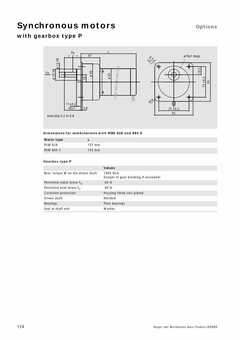
Synchronous motors Options
with gearbox type P
124 Berger Lahr Mechatronic Basic Products 8/2004
Dimensions for combinations with RSM 828 und 884 S
Gearbox type P
Motor type L
RSM 828 137 mm
RSM 884 S 193 mm
Values
Max. torque M on the driven shaft 1000 NcmDanger of gear breaking if exceeded!
Permitted radial stress Fq 60 N
Permitted axial stress Fa 40 N
Corrosion protection Housing finish zinc-plated
Driven shaft Nitrided
Bearings Plain bearings
Seal at shaft exit Washer
18
19.5
47L
ø
90
ø 5.4±0.2
R10
9575 ±0.2
9575
±0.
2ø 28
h8 ø
12 h
8
40±111±0.2
3.8ø
65
axial play 0.2 to 0.8
== ø78x1 deepFq
Fa
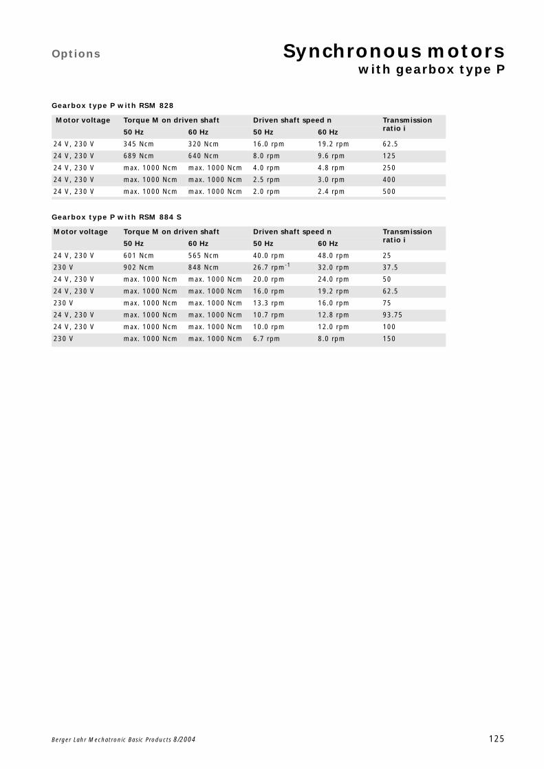
Options Synchronous motorswith gearbox type P
Berger Lahr Mechatronic Basic Products 8/2004 125
Gearbox type P with RSM 828
Gearbox type P with RSM 884 S
Motor voltage Torque M on driven shaft Driven shaft speed n Transmission ratio i50 Hz 60 Hz 50 Hz 60 Hz
24 V, 230 V 345 Ncm 320 Ncm 16.0 rpm 19.2 rpm 62.5
24 V, 230 V 689 Ncm 640 Ncm 8.0 rpm 9.6 rpm 125
24 V, 230 V max. 1000 Ncm max. 1000 Ncm 4.0 rpm 4.8 rpm 250
24 V, 230 V max. 1000 Ncm max. 1000 Ncm 2.5 rpm 3.0 rpm 400
24 V, 230 V max. 1000 Ncm max. 1000 Ncm 2.0 rpm 2.4 rpm 500
Motor voltage Torque M on driven shaft Driven shaft speed n Transmission ratio i50 Hz 60 Hz 50 Hz 60 Hz
24 V, 230 V 601 Ncm 565 Ncm 40.0 rpm 48.0 rpm 25
230 V 902 Ncm 848 Ncm 26.7 rpm-1 32.0 rpm 37.5
24 V, 230 V max. 1000 Ncm max. 1000 Ncm 20.0 rpm 24.0 rpm 50
24 V, 230 V max. 1000 Ncm max. 1000 Ncm 16.0 rpm 19.2 rpm 62.5
230 V max. 1000 Ncm max. 1000 Ncm 13.3 rpm 16.0 rpm 75
24 V, 230 V max. 1000 Ncm max. 1000 Ncm 10.7 rpm 12.8 rpm 93.75
24 V, 230 V max. 1000 Ncm max. 1000 Ncm 10.0 rpm 12.0 rpm 100
230 V max. 1000 Ncm max. 1000 Ncm 6.7 rpm 8.0 rpm 150

126 Berger Lahr Mechatronic Basic Products 8/2004

Geared motors
Berger Lahr Mechatronic Basic Products 8/2004 127
Geared motors
Gear motors from Berger Lahr ensure precise movement
in many areas of drive technology. Different gearbox types
in connection with synchronous motors (RSM) or EC mo-
tors (RECM) make a wide variety of transmission options
available specially tailored to individual customer needs.
You can also obtain further motor/gearbox combinations
with different torques, driven shaft speeds or transmission
ratios on request.
Overview of gearbox types
Gearbox type Max. continuous torque [Ncm]
Permitted radial stress Fq [N]
Permitted axial stress Fa [N]
Described on...
L 30 5 2 Page 115
T 300 30 20 Page 117
G 600 40 20 Page 119
P 1000 60 40 Page 124
P42 1500 300 100 Page 42
PK42 400 450 110 Page 43
HL 800 200 10 Page 44
P62 5000 520 120 Page 45
PLE60 4400 500 600 Page 46
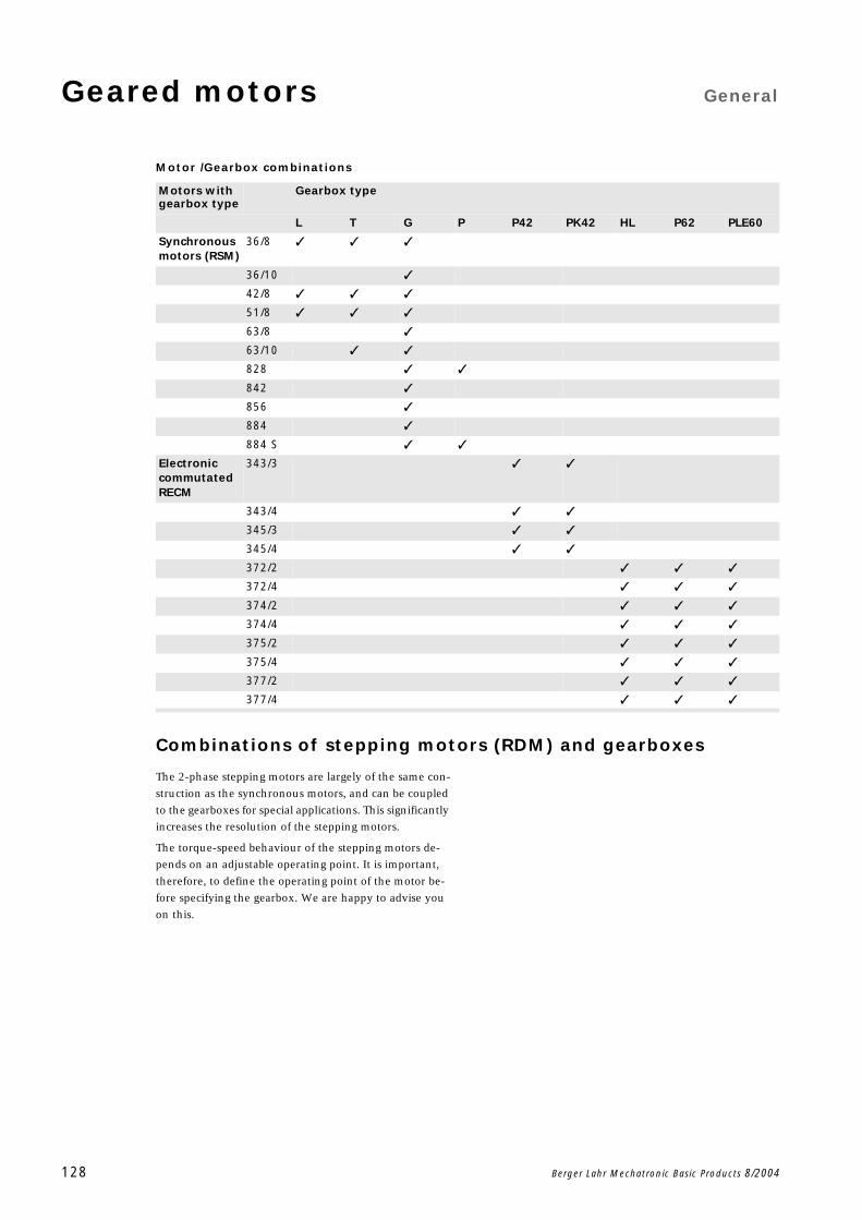
Geared motors General
128 Berger Lahr Mechatronic Basic Products 8/2004
Motor /Gearbox combinations
Combinations of stepping motors (RDM) and gearboxes
The 2-phase stepping motors are largely of the same con-
struction as the synchronous motors, and can be coupled
to the gearboxes for special applications. This significantly
increases the resolution of the stepping motors.
The torque-speed behaviour of the stepping motors de-
pends on an adjustable operating point. It is important,
therefore, to define the operating point of the motor be-
fore specifying the gearbox. We are happy to advise you
on this.
Motors with gearbox type
Gearbox type
L T G P P42 PK42 HL P62 PLE60
Synchronous motors (RSM)
36/8
36/10
42/8
51/8
63/8
63/10
828
842
856
884
884 S
Electronic commutated RECM
343/3
343/4
345/3
345/4
372/2
372/4
374/2
374/4
375/2
375/4
377/2
377/4
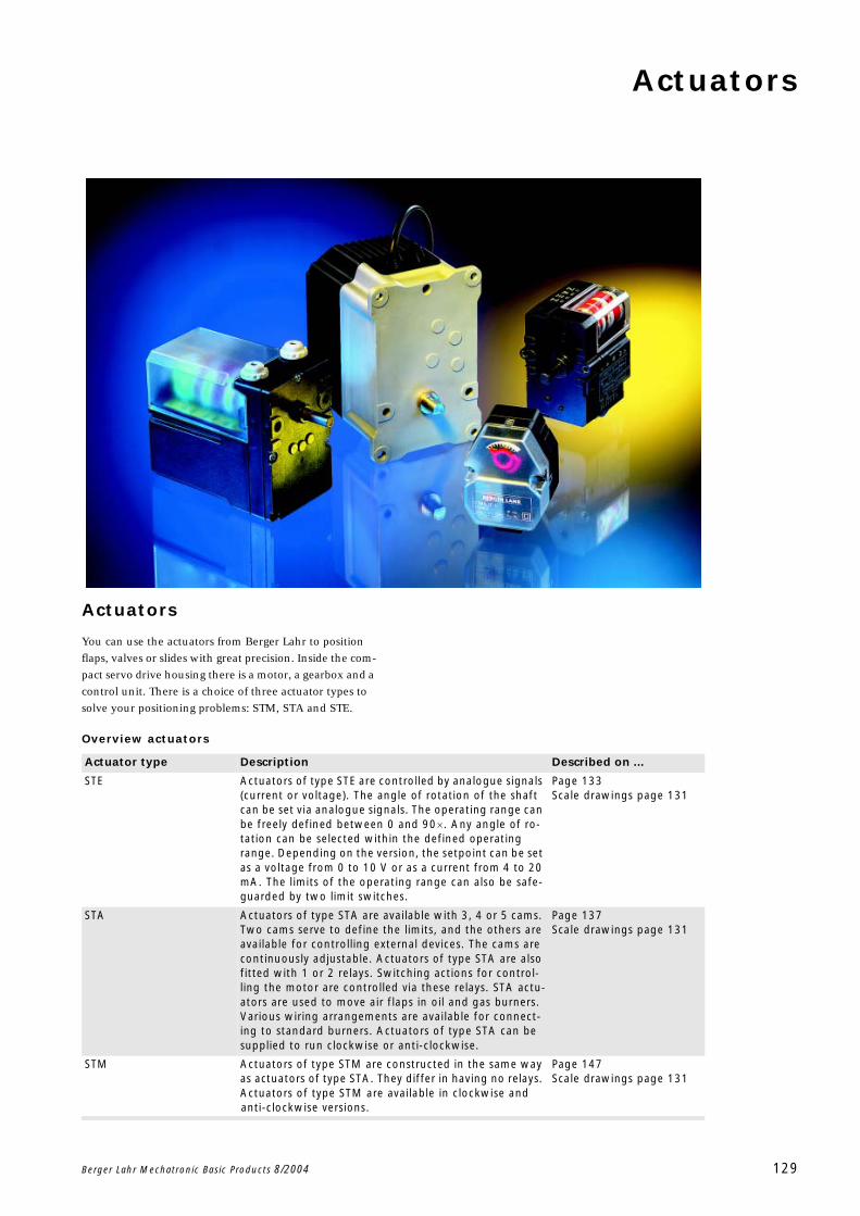
Actuators
Berger Lahr Mechatronic Basic Products 8/2004 129
Actuators
You can use the actuators from Berger Lahr to position
flaps, valves or slides with great precision. Inside the com-
pact servo drive housing there is a motor, a gearbox and a
control unit. There is a choice of three actuator types to
solve your positioning problems: STM, STA and STE.
Overview actuators
Actuator type Description Described on ...
STE Actuators of type STE are controlled by analogue signals (current or voltage). The angle of rotation of the shaft can be set via analogue signals. The operating range can be freely defined between 0 and 90. Any angle of ro-tation can be selected within the defined operating range. Depending on the version, the setpoint can be set as a voltage from 0 to 10 V or as a current from 4 to 20 mA. The limits of the operating range can also be safe-guarded by two limit switches.
Page 133Scale drawings page 131
STA Actuators of type STA are available with 3, 4 or 5 cams. Two cams serve to define the limits, and the others are available for controlling external devices. The cams are continuously adjustable. Actuators of type STA are also fitted with 1 or 2 relays. Switching actions for control-ling the motor are controlled via these relays. STA actu-ators are used to move air flaps in oil and gas burners. Various wiring arrangements are available for connect-ing to standard burners. Actuators of type STA can be supplied to run clockwise or anti-clockwise.
Page 137Scale drawings page 131
STM Actuators of type STM are constructed in the same way as actuators of type STA. They differ in having no relays. Actuators of type STM are available in clockwise and anti-clockwise versions.
Page 147Scale drawings page 131
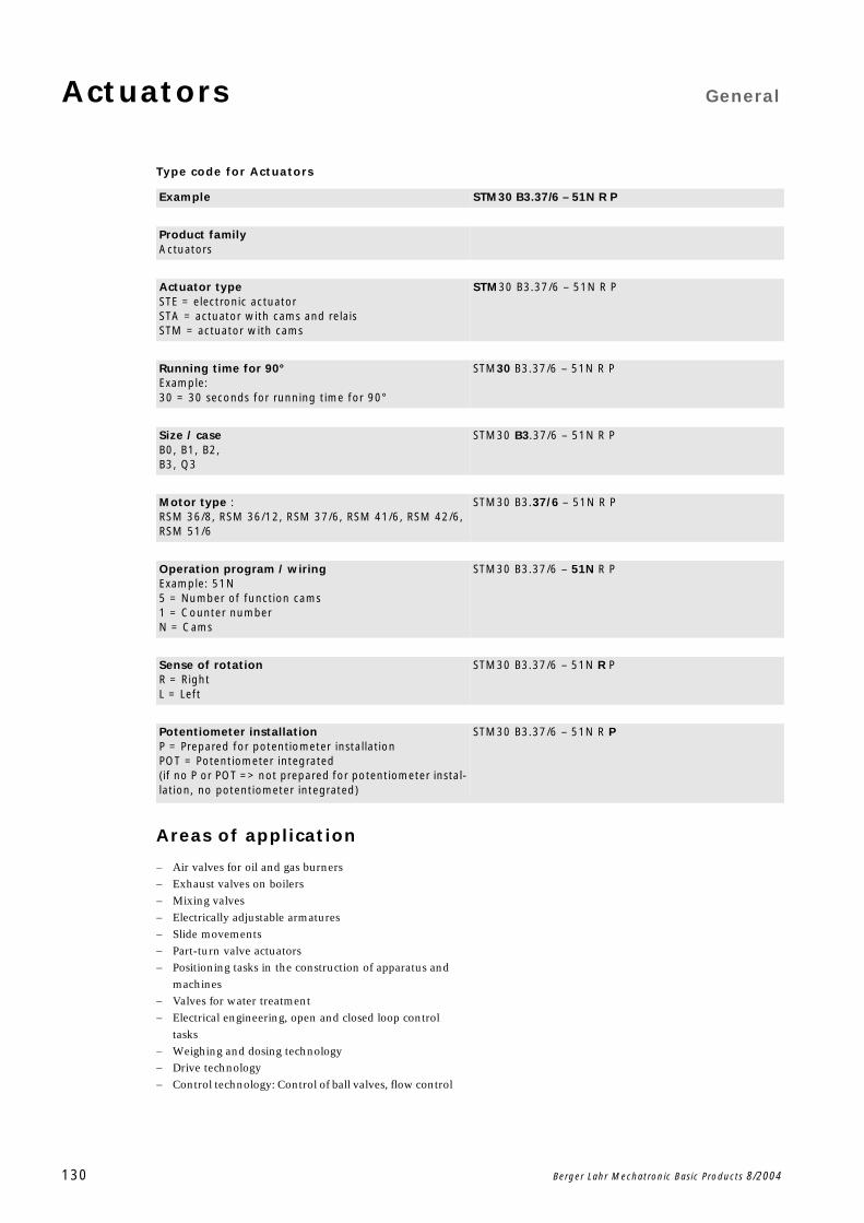
Actuators General
130 Berger Lahr Mechatronic Basic Products 8/2004
Type code for Actuators
Areas of application
Air valves for oil and gas burners
Exhaust valves on boilers
Mixing valves
Electrically adjustable armatures
Slide movements
Part-turn valve actuators
Positioning tasks in the construction of apparatus and
machines
Valves for water treatment
Electrical engineering, open and closed loop control
tasks
Weighing and dosing technology
Drive technology
Control technology: Control of ball valves, flow control
Example STM30 B3.37/6 – 51N R P
Product familyActuators
Actuator typeSTE = electronic actuatorSTA = actuator with cams and relaisSTM = actuator with cams
STM30 B3.37/6 – 51N R P
Running time for 90°Example:30 = 30 seconds for running time for 90°
STM30 B3.37/6 – 51N R P
Size / caseB0, B1, B2, B3, Q3
STM30 B3.37/6 – 51N R P
Motor type :RSM 36/8, RSM 36/12, RSM 37/6, RSM 41/6, RSM 42/6, RSM 51/6
STM30 B3.37/6 – 51N R P
Operation program / wiringExample: 51N5 = Number of function cams1 = Counter numberN = Cams
STM30 B3.37/6 – 51N R P
Sense of rotation R = RightL = Left
STM30 B3.37/6 – 51N R P
Potentiometer installationP = Prepared for potentiometer installationPOT = Potentiometer integrated(if no P or POT => not prepared for potentiometer instal-lation, no potentiometer integrated)
STM30 B3.37/6 – 51N R P
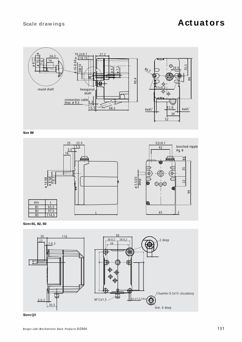
Scale drawings Actuators
Berger Lahr Mechatronic Basic Products 8/2004 131
Size B0
Sizes B1, B2, B3
Sizes Q3
51±0.2
24.3 27.2
ø 4.
2
ø 7,
2
ø 16
-0.0
4
7-0.
1ø
16-0
.04
20.5
68.2
5.3
15.5
R4.7
4.3+0.15
90,4
SW10
10.2±0.1
12,5
35,5
4x45˚ 4x45˚
2
26
84
52
14
max. ø 9,5connection cable
ø 8+
0.01
0 -0
.020
round shaft hexagonal shaft
L size 65,5
114,5 97,5
B3B2B1
25
16
7-0.
1
42
1122
35
99
2
ø 5.
5/23
de
ep
1.522.5
3.5
ø 8
h8ø
14 h
8
L
52±0.1
65
bunched nipplePg 9
30 11622
2:0,3
30,5
6:0,2
9038:0,238:0,2
682 deep
min. 6 deep
Chamfer 0.5x15 circulatory
5,4 0,2(4x)+-M12x1,5
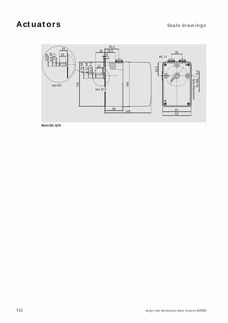
Actuators Scale drawings
132 Berger Lahr Mechatronic Basic Products 8/2004
Sizes Q5, Q15
7-0.
1
14 h
825
20
size Q5size Q15
ø 8
h8
ø 12
h8
10.5
-0.2
ø68
ø 18
h8
58 9193
30
22
1
33,54
144
142
45,5
6,443
,5
36
PG 11
for
M6
conn
ectin
g ho
le
149
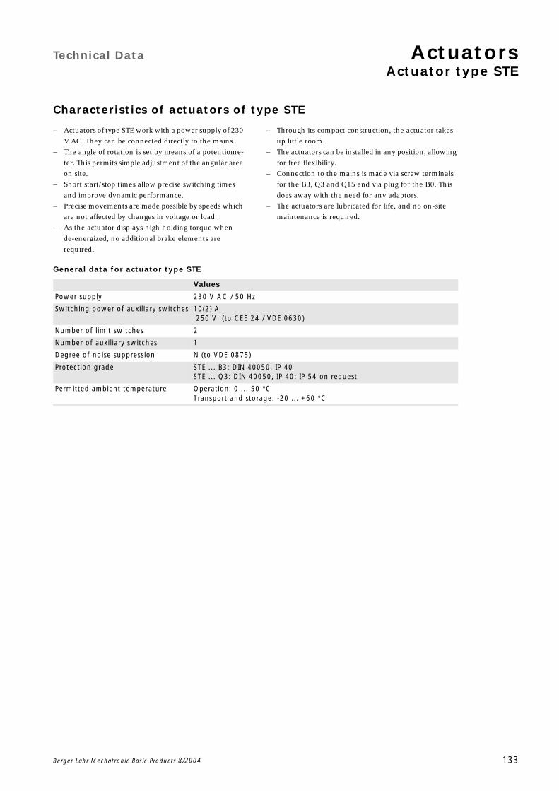
Technical Data ActuatorsActuator type STE
Berger Lahr Mechatronic Basic Products 8/2004 133
Characteristics of actuators of type STE
Actuators of type STE work with a power supply of 230
V AC. They can be connected directly to the mains.
The angle of rotation is set by means of a potentiome-
ter. This permits simple adjustment of the angular area
on site.
Short start/stop times allow precise switching times
and improve dynamic performance.
Precise movements are made possible by speeds which
are not affected by changes in voltage or load.
As the actuator displays high holding torque when
de-energized, no additional brake elements are
required.
Through its compact construction, the actuator takes
up little room.
The actuators can be installed in any position, allowing
for free flexibility.
Connection to the mains is made via screw terminals
for the B3, Q3 and Q15 and via plug for the B0. This
does away with the need for any adaptors.
The actuators are lubricated for life, and no on-site
maintenance is required.
General data for actuator type STE
Values
Power supply 230 V AC / 50 Hz
Switching power of auxiliary switches 10(2) A 250 V (to CEE 24 / VDE 0630)
Number of limit switches 2
Number of auxiliary switches 1
Degree of noise suppression N (to VDE 0875)
Protection grade STE ... B3: DIN 40050, IP 40STE ... Q3: DIN 40050, IP 40; IP 54 on request
Permitted ambient temperature Operation: 0 ... 50 CTransport and storage: -20 ... +60 C
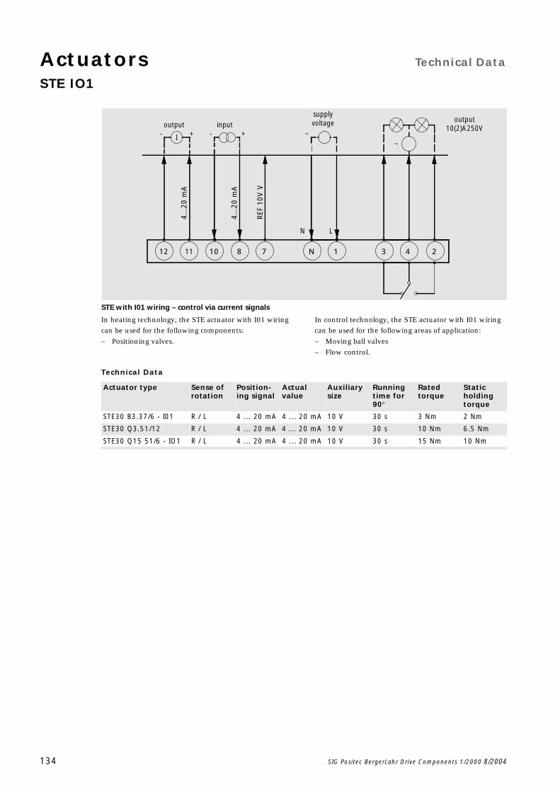
Actuators Technical Data
STE IO1
134 SIG Positec BergerLahr Drive Components 1/2000 8/2004
STE with I01 wiring – control via current signals
In heating technology, the STE actuator with I01 wiring
can be used for the following components:
Positioning valves.
In control technology, the STE actuator with I01 wiring
can be used for the following areas of application:
Moving ball valves
Flow control.
Technical Data
~
output10(2)A250Voutput
supplyvoltage
I +- ~- +input
243REF
10V
V
4...2
0 m
A
4...2
0 m
AN L
12 11 10 8 7 N 1
Actuator type Sense of rotation
Position-ing signal
Actual value
Auxiliary size
Running time for 90
Rated torque
Static holding torque
STE30 B3.37/6 - I01 R / L 4 ... 20 mA 4 ... 20 mA 10 V 30 s 3 Nm 2 Nm
STE30 Q3.51/12 R / L 4 ... 20 mA 4 ... 20 mA 10 V 30 s 10 Nm 6.5 Nm
STE30 Q15 51/6 - IO1 R / L 4 ... 20 mA 4 ... 20 mA 10 V 30 s 15 Nm 10 Nm
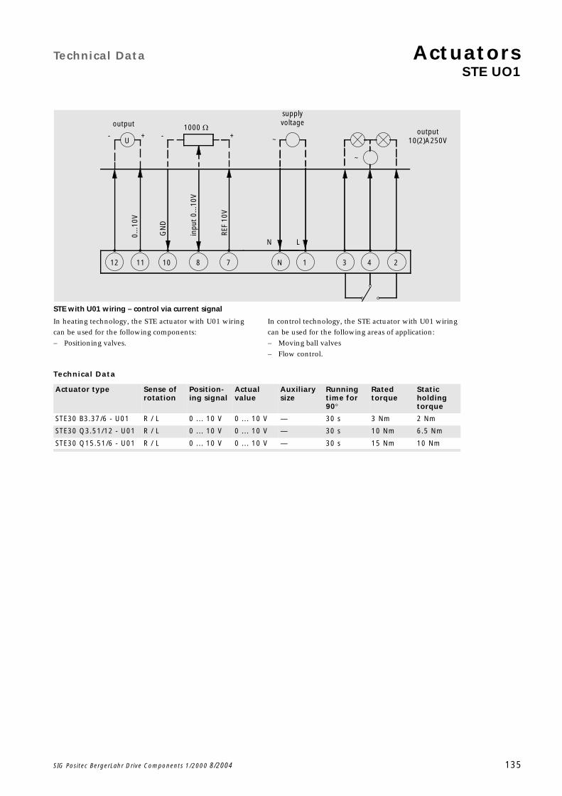
Technical Data ActuatorsSTE UO1
SIG Positec BergerLahr Drive Components 1/2000 8/2004 135
STE with U01 wiring – control via current signal
In heating technology, the STE actuator with U01 wiring
can be used for the following components:
Positioning valves.
In control technology, the STE actuator with U01 wiring
can be used for the following areas of application:
Moving ball valves
Flow control.
Technical Data
~
~U+-- + output
10(2)A250V
supplyvoltage
REF
10V
inpu
t 0.
..10V
output 1000 Ω
243
0...1
0V
GN
D
N L
12 11 10 8 7 N 1
Actuator type Sense of rotation
Position-ing signal
Actual value
Auxiliary size
Running time for 90
Rated torque
Static holding torque
STE30 B3.37/6 - U01 R / L 0 ... 10 V 0 ... 10 V — 30 s 3 Nm 2 Nm
STE30 Q3.51/12 - U01 R / L 0 ... 10 V 0 ... 10 V — 30 s 10 Nm 6.5 Nm
STE30 Q15.51/6 - U01 R / L 0 ... 10 V 0 ... 10 V — 30 s 15 Nm 10 Nm

Actuators
136 Berger Lahr Mechatronic Basic Products 8/2004
Technical Data ActuatorsActuator type STA
Berger Lahr Mechatronic Basic Products 8/2004 137
Characteristics of actuators of type STA
The cams can be continuously adjusted by hand, fine
tuning with a screw-driver. This makes on-site adjust-
ment easier.
Short start/stop times allow precise switching times
and ensure good dynamic performance.
Precise movements are made possible by speeds which
are not affected by changes in voltage or load.
As the actuator displays high holding torque when
de-energized, no additional brake elements are
required.
Through its compact construction, the actuator takes
up little room.
Actuators can be installed in any plane.
Connection to the mains is made via screw terminals
for the B1, B2 and B3 and by plug for the B0. This does
away with the need for any adaptors.
The optional version with a potentiometer allows a
feedback signal on the angle of rotation to be
evaluated.
The actuators are lubricated for life, and no on-site
maintenance is required.
General data for actuator type STA
Accessories: potentiometer installation set
The angle of rotation of the actuators can be recorded by
a mechanically coupled potentiometer and passed to an
external control unit for further processing. All actuators
whose type code ends in a "P" can be retro-fitted with a
potentiometer.
Potentiometer installation sets with resistor values of
100 and 1000 through 90 are available.
Values
Power supply 230 V AC / 50Hz
Switching power of auxiliary switches 10(2) A 250 V (to CEE 24 / VDE 0630)
Protection grade DIN 40050, IP 40STA, STM ... Q3 ... are available with IP 54
Permitted ambient temperature Operation: 0 ... 60 CTransport and storage: -20 ... +60 C
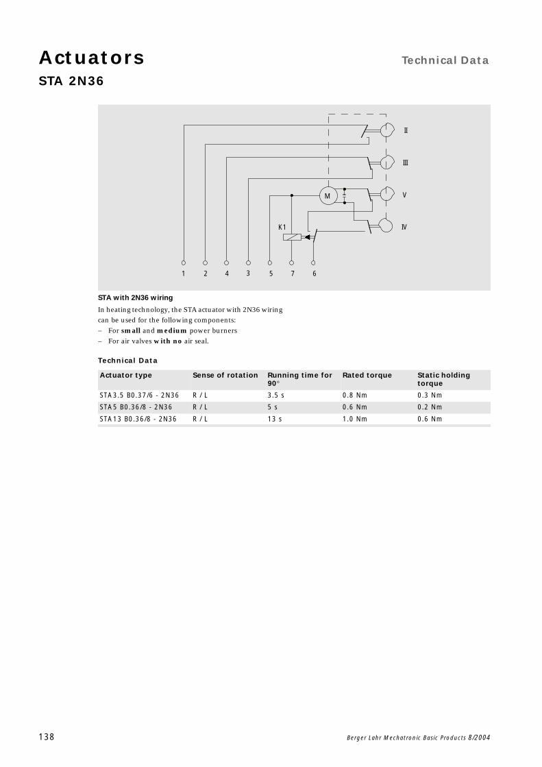
Actuators Technical Data
STA 2N36
138 Berger Lahr Mechatronic Basic Products 8/2004
STA with 2N36 wiring
In heating technology, the STA actuator with 2N36 wiring
can be used for the following components:
For small and medium power burners
For air valves with no air seal.
Technical Data
K1
1
M
42 3 5 7 6
IV
III
V
II
Actuator type Sense of rotation Running time for 90
Rated torque Static holding torque
STA3.5 B0.37/6 - 2N36 R / L 3.5 s 0.8 Nm 0.3 Nm
STA5 B0.36/8 - 2N36 R / L 5 s 0.6 Nm 0.2 Nm
STA13 B0.36/8 - 2N36 R / L 13 s 1.0 Nm 0.6 Nm
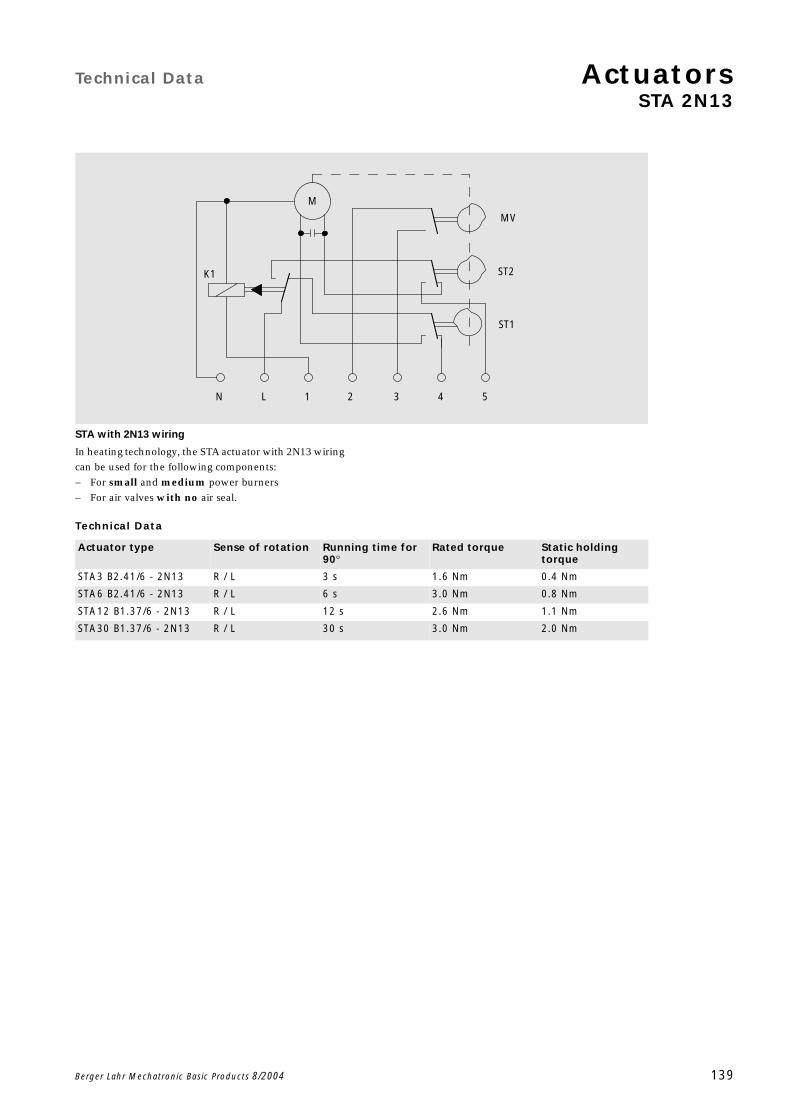
Technical Data ActuatorsSTA 2N13
Berger Lahr Mechatronic Basic Products 8/2004 139
STA with 2N13 wiring
In heating technology, the STA actuator with 2N13 wiring
can be used for the following components:
For small and medium power burners
For air valves with no air seal.
Technical Data
K1
N L 1 2
M
ST2
ST1
3
MV
4 5
Actuator type Sense of rotation Running time for 90
Rated torque Static holding torque
STA3 B2.41/6 - 2N13 R / L 3 s 1.6 Nm 0.4 Nm
STA6 B2.41/6 - 2N13 R / L 6 s 3.0 Nm 0.8 Nm
STA12 B1.37/6 - 2N13 R / L 12 s 2.6 Nm 1.1 Nm
STA30 B1.37/6 - 2N13 R / L 30 s 3.0 Nm 2.0 Nm
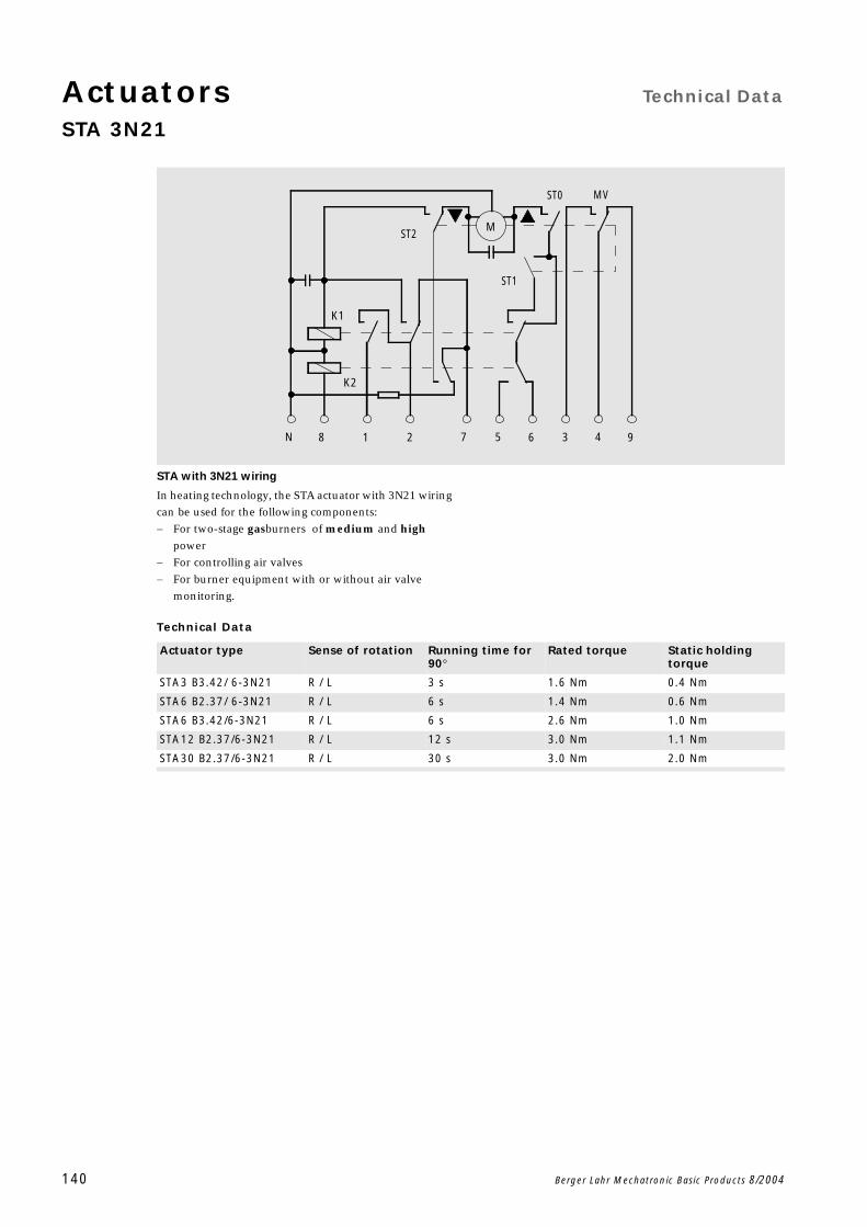
Actuators Technical Data
STA 3N21
140 Berger Lahr Mechatronic Basic Products 8/2004
STA with 3N21 wiring
In heating technology, the STA actuator with 3N21 wiring
can be used for the following components:
For two-stage gasburners of medium and high
power
For controlling air valves
For burner equipment with or without air valve
monitoring.
Technical Data
K1
K2
6N 8 1 2 7 5 3 4 9
M
ST1
ST0 MV
ST2
Actuator type Sense of rotation Running time for 90
Rated torque Static holding torque
STA3 B3.42/ 6-3N21 R / L 3 s 1.6 Nm 0.4 Nm
STA6 B2.37/ 6-3N21 R / L 6 s 1.4 Nm 0.6 Nm
STA6 B3.42/6-3N21 R / L 6 s 2.6 Nm 1.0 Nm
STA12 B2.37/6-3N21 R / L 12 s 3.0 Nm 1.1 Nm
STA30 B2.37/6-3N21 R / L 30 s 3.0 Nm 2.0 Nm
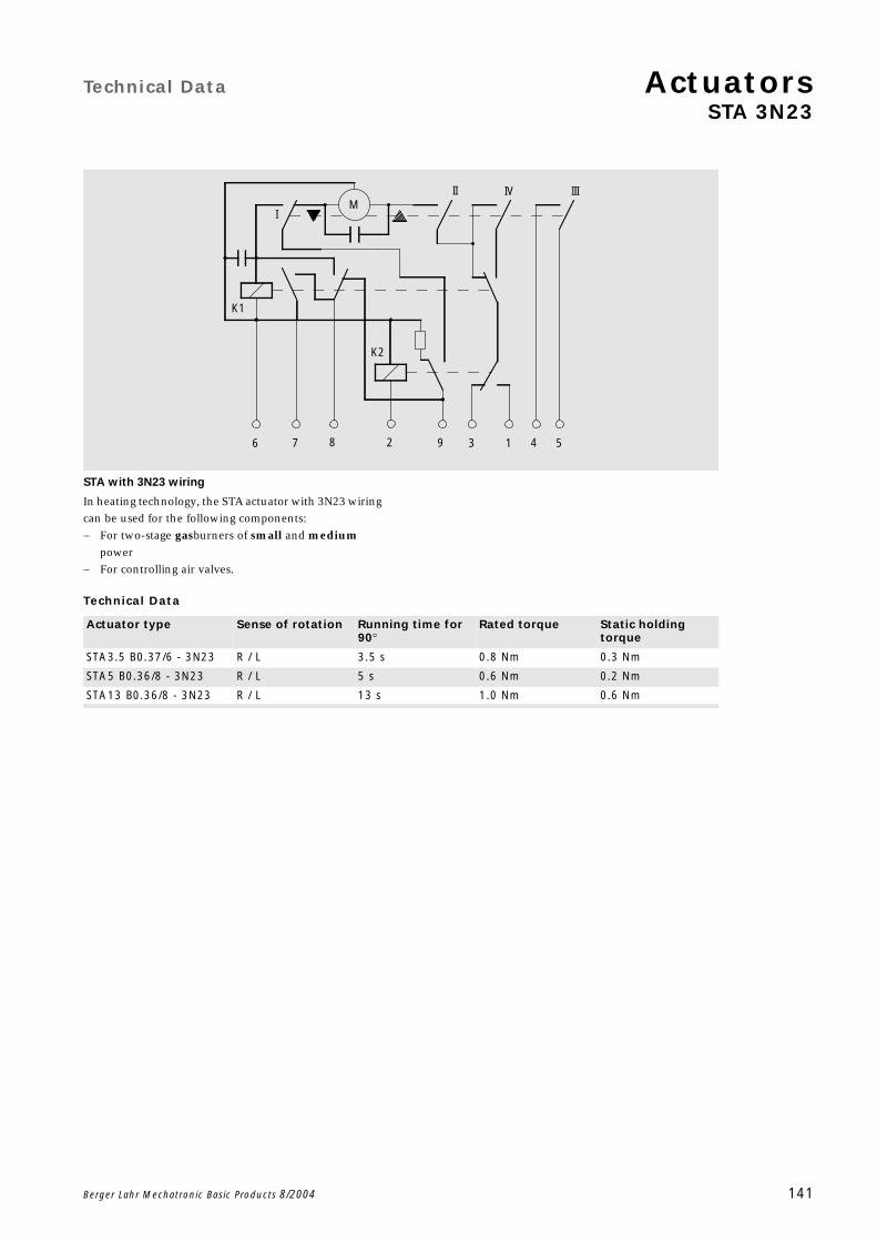
Technical Data ActuatorsSTA 3N23
Berger Lahr Mechatronic Basic Products 8/2004 141
STA with 3N23 wiring
In heating technology, the STA actuator with 3N23 wiring
can be used for the following components:
For two-stage gasburners of small and medium
power
For controlling air valves.
Technical Data
K2
K1
76 8 2 9 3 1 4 5
IV IIIII
IM
Actuator type Sense of rotation Running time for 90
Rated torque Static holding torque
STA3.5 B0.37/6 - 3N23 R / L 3.5 s 0.8 Nm 0.3 Nm
STA5 B0.36/8 - 3N23 R / L 5 s 0.6 Nm 0.2 Nm
STA13 B0.36/8 - 3N23 R / L 13 s 1.0 Nm 0.6 Nm
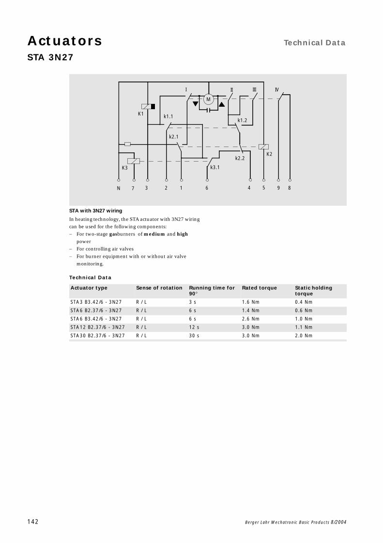
Actuators Technical Data
STA 3N27
142 Berger Lahr Mechatronic Basic Products 8/2004
STA with 3N27 wiring
In heating technology, the STA actuator with 3N27 wiring
can be used for the following components:
For two-stage gasburners of medium and high
power
For controlling air valves
For burner equipment with or without air valve
monitoring.
Technical Data
7
K3
N 3 2
k2.1
K1 k1.1
K2
k3.1
1 6 4 5
k2.2
I
M
II
k1.2
III
9 8
IV
Actuator type Sense of rotation Running time for 90
Rated torque Static holding torque
STA3 B3.42/6 - 3N27 R / L 3 s 1.6 Nm 0.4 Nm
STA6 B2.37/6 - 3N27 R / L 6 s 1.4 Nm 0.6 Nm
STA6 B3.42/6 - 3N27 R / L 6 s 2.6 Nm 1.0 Nm
STA12 B2.37/6 - 3N27 R / L 12 s 3.0 Nm 1.1 Nm
STA30 B2.37/6 - 3N27 R / L 30 s 3.0 Nm 2.0 Nm
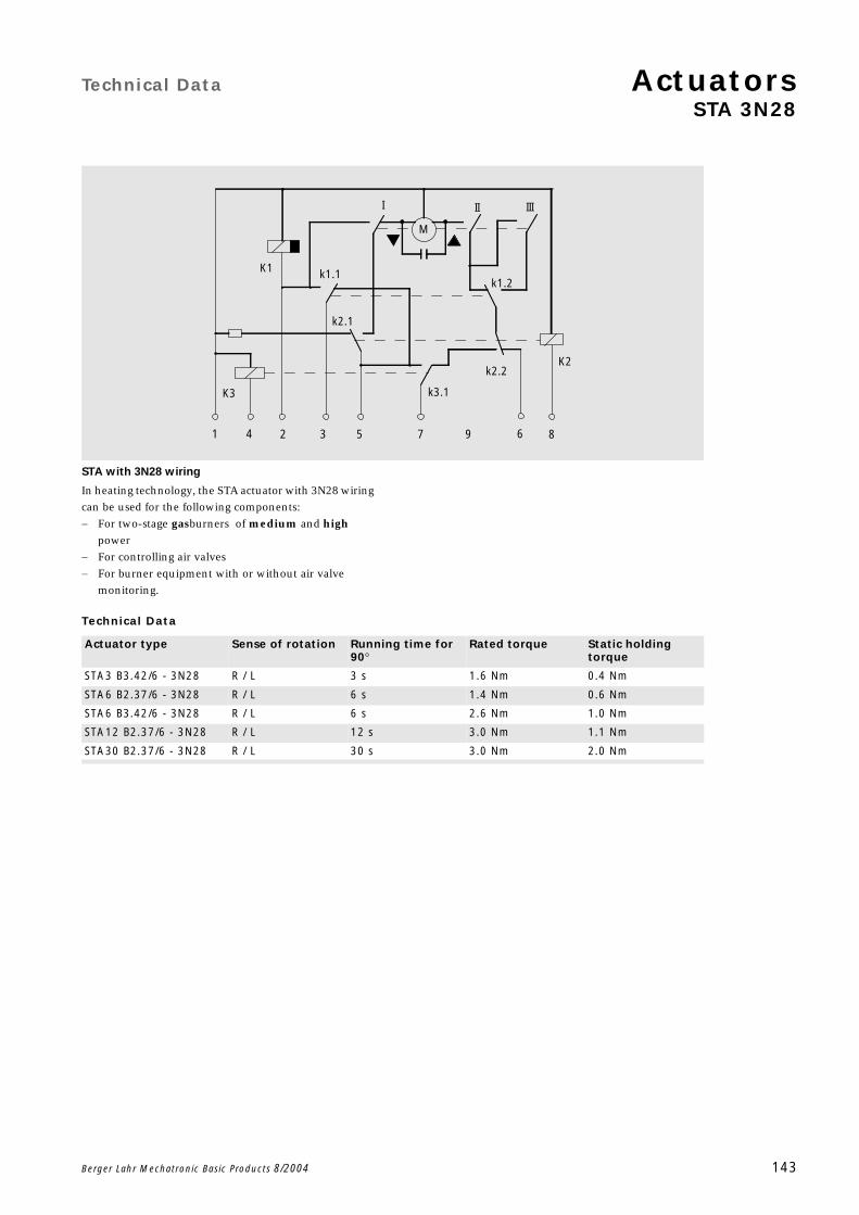
Technical Data ActuatorsSTA 3N28
Berger Lahr Mechatronic Basic Products 8/2004 143
STA with 3N28 wiring
In heating technology, the STA actuator with 3N28 wiring
can be used for the following components:
For two-stage gasburners of medium and high
power
For controlling air valves
For burner equipment with or without air valve
monitoring.
Technical Data
M
III III
K1 k1.1
k2.1
k1.2
K2k2.2
k3.1K3
1 4 62 3 5 7 9 8
Actuator type Sense of rotation Running time for 90
Rated torque Static holding torque
STA3 B3.42/6 - 3N28 R / L 3 s 1.6 Nm 0.4 Nm
STA6 B2.37/6 - 3N28 R / L 6 s 1.4 Nm 0.6 Nm
STA6 B3.42/6 - 3N28 R / L 6 s 2.6 Nm 1.0 Nm
STA12 B2.37/6 - 3N28 R / L 12 s 3.0 Nm 1.1 Nm
STA30 B2.37/6 - 3N28 R / L 30 s 3.0 Nm 2.0 Nm
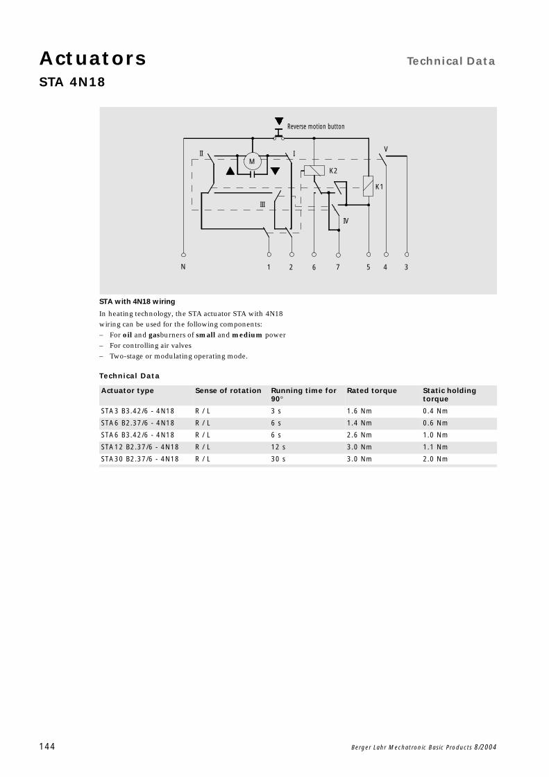
Actuators Technical Data
STA 4N18
144 Berger Lahr Mechatronic Basic Products 8/2004
STA with 4N18 wiring
In heating technology, the STA actuator STA with 4N18
wiring can be used for the following components:
For oil and gasburners of small and medium power
For controlling air valves
Two-stage or modulating operating mode.
Technical Data
Reverse motion button
K2
K1
N 1 2 6 7 5 4 3
M
IV
V
III
II I
Actuator type Sense of rotation Running time for 90
Rated torque Static holding torque
STA3 B3.42/6 - 4N18 R / L 3 s 1.6 Nm 0.4 Nm
STA6 B2.37/6 - 4N18 R / L 6 s 1.4 Nm 0.6 Nm
STA6 B3.42/6 - 4N18 R / L 6 s 2.6 Nm 1.0 Nm
STA12 B2.37/6 - 4N18 R / L 12 s 3.0 Nm 1.1 Nm
STA30 B2.37/6 - 4N18 R / L 30 s 3.0 Nm 2.0 Nm
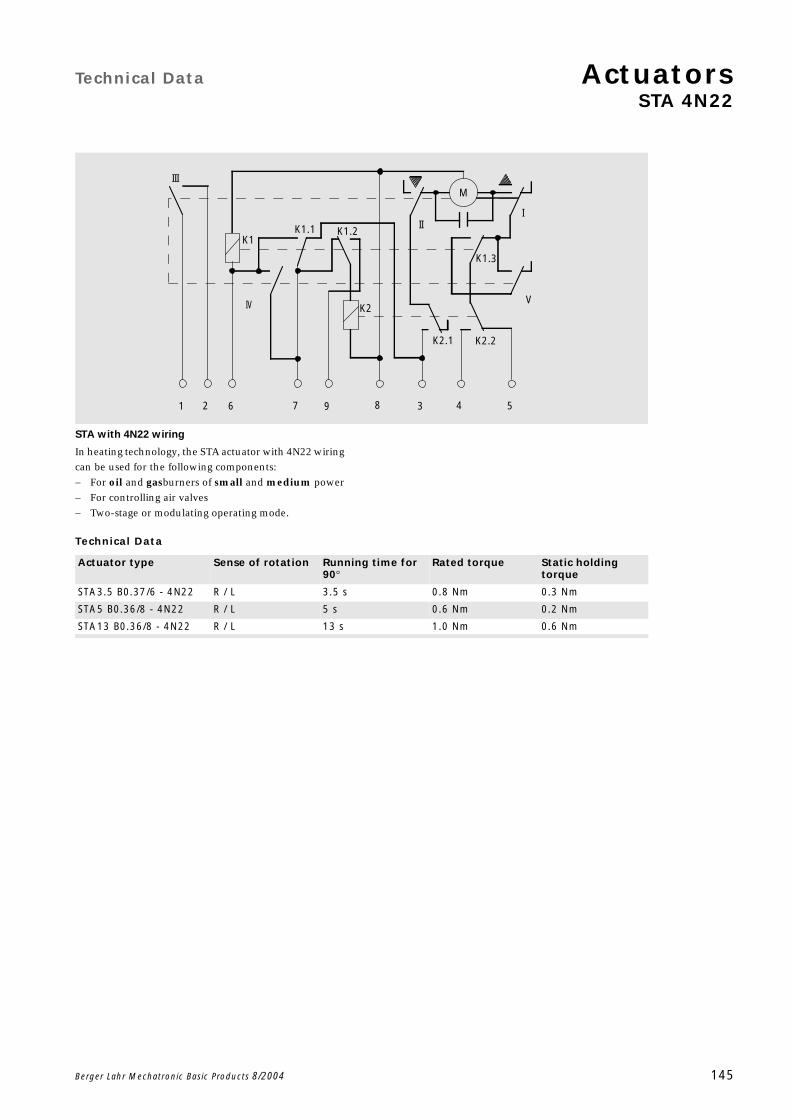
Technical Data ActuatorsSTA 4N22
Berger Lahr Mechatronic Basic Products 8/2004 145
STA with 4N22 wiring
In heating technology, the STA actuator with 4N22 wiring
can be used for the following components:
For oil and gasburners of small and medium power
For controlling air valves
Two-stage or modulating operating mode.
Technical Data
K2
K1
K2.1 K2.2
K1.1
K1.3
K1.2
I
1 62 9 7 8 3 4 5
IV V
II
MIII
Actuator type Sense of rotation Running time for 90
Rated torque Static holding torque
STA3.5 B0.37/6 - 4N22 R / L 3.5 s 0.8 Nm 0.3 Nm
STA5 B0.36/8 - 4N22 R / L 5 s 0.6 Nm 0.2 Nm
STA13 B0.36/8 - 4N22 R / L 13 s 1.0 Nm 0.6 Nm
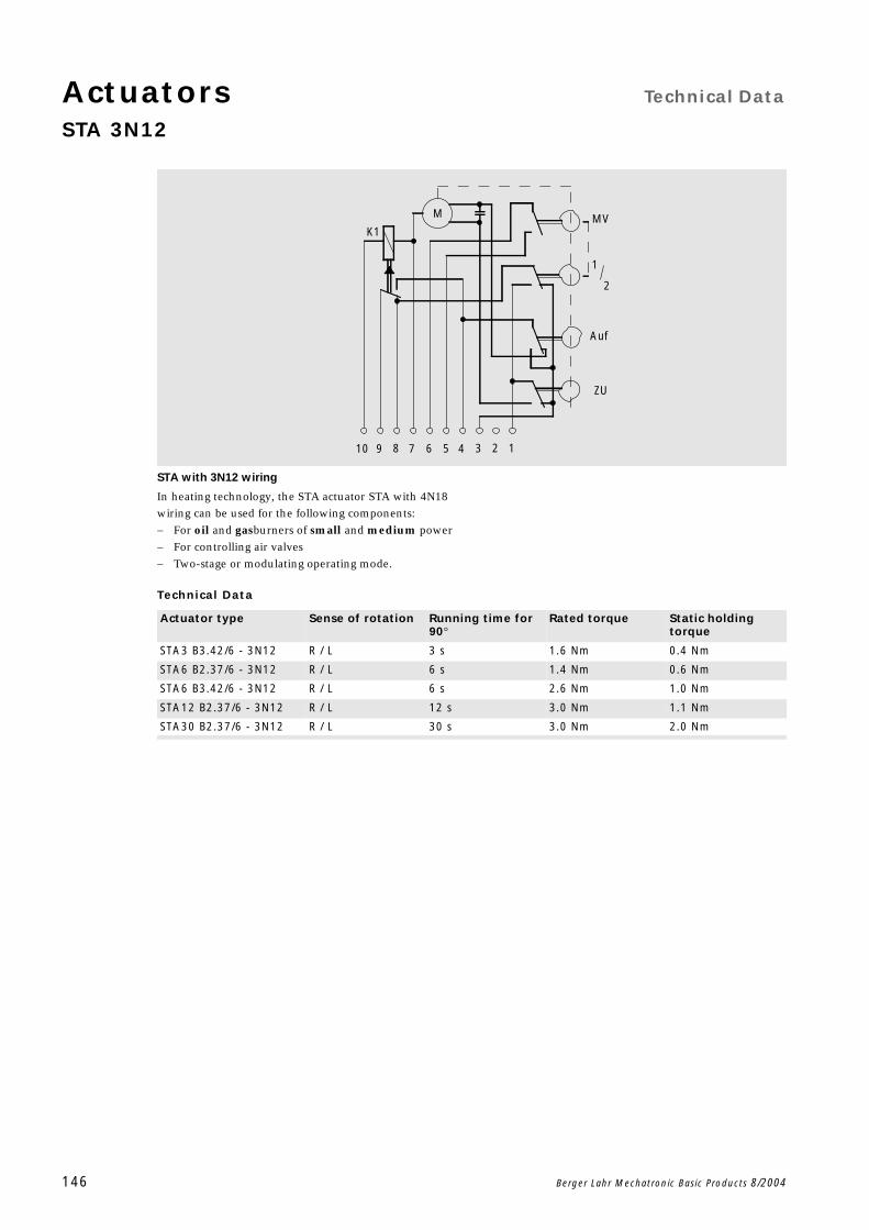
Actuators Technical Data
STA 3N12
146 Berger Lahr Mechatronic Basic Products 8/2004
STA with 3N12 wiring
In heating technology, the STA actuator STA with 4N18
wiring can be used for the following components:
For oil and gasburners of small and medium power
For controlling air valves
Two-stage or modulating operating mode.
Technical Data
K1
M
9 8 7 6 25 4 3
Auf
ZU
2
1
MV
110
Actuator type Sense of rotation Running time for 90
Rated torque Static holding torque
STA3 B3.42/6 - 3N12 R / L 3 s 1.6 Nm 0.4 Nm
STA6 B2.37/6 - 3N12 R / L 6 s 1.4 Nm 0.6 Nm
STA6 B3.42/6 - 3N12 R / L 6 s 2.6 Nm 1.0 Nm
STA12 B2.37/6 - 3N12 R / L 12 s 3.0 Nm 1.1 Nm
STA30 B2.37/6 - 3N12 R / L 30 s 3.0 Nm 2.0 Nm
Technical Data ActuatorsActuator type STM
Berger Lahr Mechatronic Basic Products 8/2004 147
Characteristics of actuators of type STM
The cams can be continuously adjusted by hand, fine
tuning with a screw-driver. This makes on-site adjust-
ment easier.
Short start/stop times allow precise switching times
and ensure good dynamic performance.
Precise movements are made possible by speeds which
are not affected by changes in voltage or load.
As the actuator displays high holding torque when
de-energized, no additional brake elements are
required.
Through its compact construction, the actuator takes
up little room.
Actuators can be installed in any plane.
Connection to the mains is made via screw terminals
for the B1, B2, B3 and Q3 by plug for the B0. This does
away with the need for any adaptors.
The optional version with a potentiometer allows a
feedback signal on the angle of rotation to be evaluat-
ed.
The actuators are lubricated for life, and no on-site
maintenance is required.
General data for actuator type STM
Accessories: potentiometer installation set
The angle of rotation of the actuators can be recorded by
a mechanically coupled potentiometer and passed to an
external control unit for further processing. All actuators
whose type code ends in a "P" can be retro-fitted with a
potentiometer.
Potentiometer installation sets with resistor values of
100 and 1000 through 90 are available.
Values
Power supply 230 V AC / 50Hz
Switching power of auxiliary switches 10(2) A 250 V (to CEE 24 / VDE 0630)
Protection grade DIN 40050, IP 40STA, STM ... Q3 ... are available with IP 54
Permitted ambient temperature Operation: 0 ... 60 CTransport and storage: -20 ... +60 C
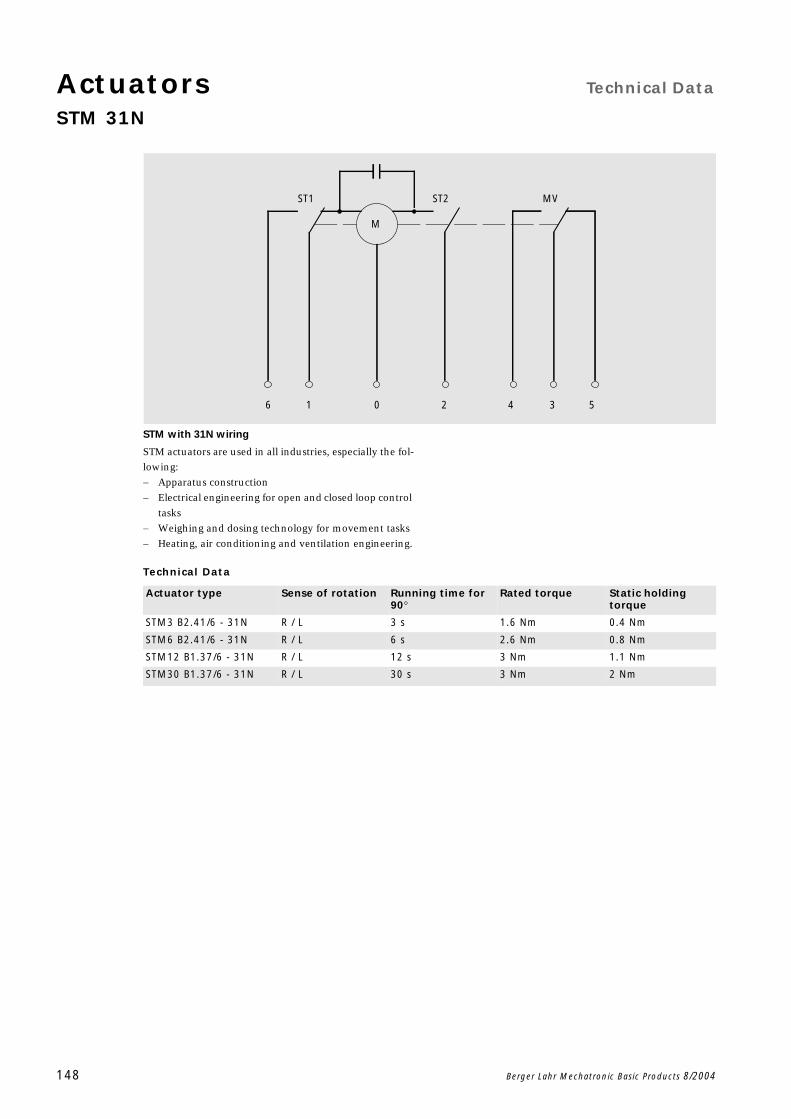
Actuators Technical Data
STM 31N
148 Berger Lahr Mechatronic Basic Products 8/2004
STM with 31N wiring
STM actuators are used in all industries, especially the fol-
lowing:
Apparatus construction
Electrical engineering for open and closed loop control
tasks
Weighing and dosing technology for movement tasks
Heating, air conditioning and ventilation engineering.
Technical Data
5
ST2
M
ST1
40 216 3
MV
Actuator type Sense of rotation Running time for 90
Rated torque Static holding torque
STM3 B2.41/6 - 31N R / L 3 s 1.6 Nm 0.4 Nm
STM6 B2.41/6 - 31N R / L 6 s 2.6 Nm 0.8 Nm
STM12 B1.37/6 - 31N R / L 12 s 3 Nm 1.1 Nm
STM30 B1.37/6 - 31N R / L 30 s 3 Nm 2 Nm
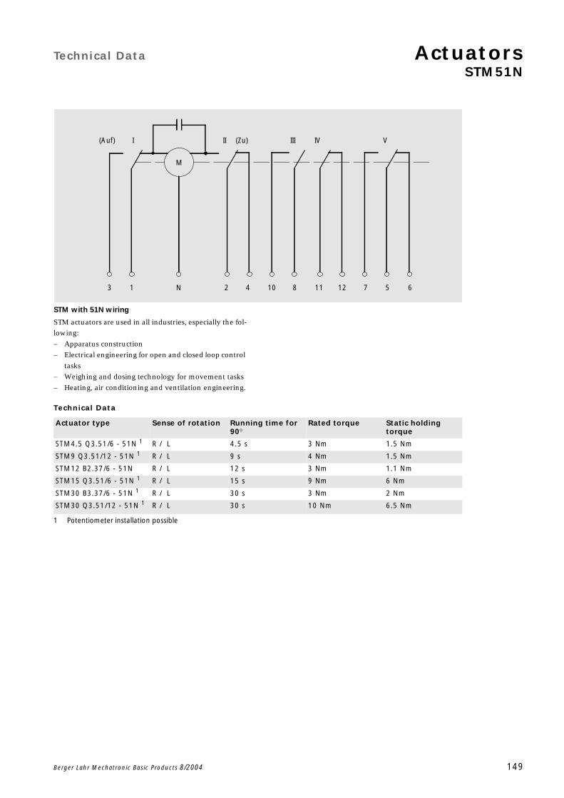
Technical Data ActuatorsSTM51N
Berger Lahr Mechatronic Basic Products 8/2004 149
STM with 51N wiring
STM actuators are used in all industries, especially the fol-
lowing:
Apparatus construction
Electrical engineering for open and closed loop control
tasks
Weighing and dosing technology for movement tasks
Heating, air conditioning and ventilation engineering.
Technical Data
7 5 6
VIV
1211
II
M
I
104N 213 8
III(Zu)(Auf)
Actuator type Sense of rotation Running time for 90
Rated torque Static holding torque
STM4.5 Q3.51/6 - 51N 1 R / L 4.5 s 3 Nm 1.5 Nm
STM9 Q3.51/12 - 51N 1
1 Potentiometer installation possible
R / L 9 s 4 Nm 1.5 Nm
STM12 B2.37/6 - 51N R / L 12 s 3 Nm 1.1 Nm
STM15 Q3.51/6 - 51N 1 R / L 15 s 9 Nm 6 Nm
STM30 B3.37/6 - 51N 1 R / L 30 s 3 Nm 2 Nm
STM30 Q3.51/12 - 51N 1 R / L 30 s 10 Nm 6.5 Nm
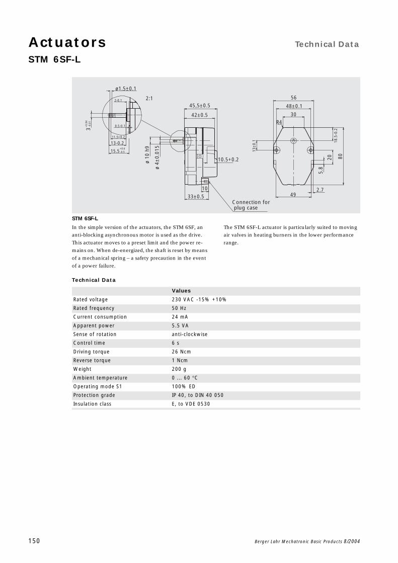
Actuators Technical Data
STM 6SF-L
150 Berger Lahr Mechatronic Basic Products 8/2004
STM 6SF-L
In the simple version of the actuators, the STM 6SF, an
anti-blocking asynchronous motor is used as the drive.
This actuator moves to a preset limit and the power re-
mains on. When de-energized, the shaft is reset by means
of a mechanical spring – a safety precaution in the event
of a power failure.
The STM 6SF-L actuator is particularly suited to moving
air valves in heating burners in the lower performance
range.
Technical Data
30R4
56
80
5.8
13±
0.1
ø 4±
0.01
5
ø 10
h9
48±0.1
18.5
-0.2
20
2.749
10.5+0.2
45,5±0.5
42±0.5
33±0.5
10
plug caseConnection for
ø1.5±0.1
2:1
0.5-0.1
11.5+0.2
13-0.2
2-0.1
15.5+0.6 -0.5
+0.
04
-0.0
13
Values
Rated voltage 230 VAC -15% +10%
Rated frequency 50 Hz
Current consumption 24 mA
Apparent power 5.5 VA
Sense of rotation anti-clockwise
Control time 6 s
Driving torque 26 Ncm
Reverse torque 1 Ncm
Weight 200 g
Ambient temperature 0 ... 60 C
Operating mode S1 100% ED
Protection grade IP 40, to DIN 40 050
Insulation class E, to VDE 0530

13.2
01 G
B 16
/8/0
4 Ri
edel
Gm
bH M
ünch
en/V
TD ·
Tech
nisc
he Ä
nder
unge
n vo
rbeh
alte
n · P
rinte
d in
Ger
man
y
Berger Lahr offers you the positioning and automation solutions you need, based on our tried and proven series of products. Our comprehensive engineering and consultingservice is ready to support and advise you every step of the way.
Berger Lahr is a member company of the Schneider Electric Group. With its Merlin Gerlin, Square D and Telemecanique brands, Sch-neider Electric is one of the lead-ing providers of electrical and automation-engineering solu-tions.
Berger Lahr GmbH & Co. KGBreslauer Straße 7 · D-77933 LahrTel. +49 (0) 7821-946-401 · Fax ++49 (0) 7821-946-347Internet: http://www.berger-lahr.de
Information in this typeface is current at the time of publication. However, printing errors or mis-stakes are not excluded. We expressly reserve the right to make structural modifications or varia-tions.