Embed Size (px)
DESCRIPTION
composite insulators
Citation preview

The very Best.
www.ppc insu l a tors .com
Only a company that develops,
produces and delivers products
worldwide can provide the optimal
solution for your requirements.
The specialists of PPC Insulators
are dedicated to supplying you with
superior advice and global support.
PPC Insulators quality products
and service provide time-tested
value to fulfill your needs!
Please visit us on the web at
www.ppcinsuators.com
That’s what we deliver.
Re
visi
on
1/
20
03
Hollow Insulators – Custom Design
The very Best.

Design has long been restricted by limitations
in material and production, complicating
introduction of new insulator styles.
Long lead times required for engineering,
preparation and tooling has mandated
product uniformity and strict
recommendations at the cost of
function-specific design.
> ISO 9001 > IEC
The Design SpecialistAt Your Service
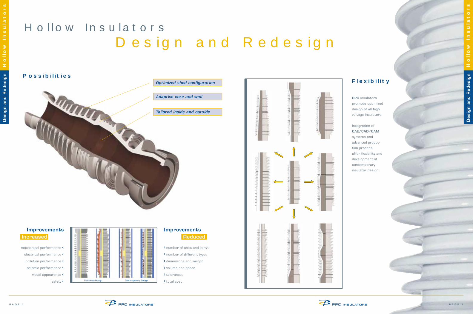
IndexReduced dimensions and weight with increasedstrength and appearance > Design and Redesign
Possibilities PAGE 4
Improvements PAGE 4
Flexibility PAGE 5
> K-valueIncreased Pollution Performance and
Equalized Filed Distribution PAGE 6
Standards PAGE 7
Dimensions PAGE 7
Material and Specific Strength PAGE 7
> Design CriteriaDetermination of Type Test Withstand
Bending Moment PAGE 9
Determination of Type Test Withstand
Design Pressure PAGE 9
Influence of Fitting and Clamping Design PAGE 10
> Pollution PerformancePollution Levels PAGE 12
Shed Design PAGE 14
> TolerancesGeneral Tolerances PAGE 16
Deviation from Roundness PAGE 16
Tolerance of Wall Thickness PAGE 16
Tolerance of Form and Position PAGE 17
Finish of Ground Surface PAGE 17
> Test and Inspection PAGE 19
New Development
Major improvements
now set new standards.
> Isostatic process with
shorter lead-times, tighter
tolerances and flexible design
offer unprecedented
possibilities for development
and prototype production.
> Integrated computer systems
including CAE/CAD/CAM and
on-line scheduling speeds introduction
of new types.
> K-value, the essential calculation
of insulator pollution performance, consider
creepage distance and shape to open new
opportunities for optimization.
Intr
od
uc
tio
nH
ollow
Insula
tors
Intr
od
uc
tio
nH
ollow
Insula
tors
The traditional high voltage insulator
is subject to new development focusing on
improved performance with reduced sizes.
We are at your service to develop custom tailored insulators for your specif ic requirements!
PAGE 5PAGE 4
Hollow InsulatorsDesign and Redesign
mechanical performance <
electrical performance <
pollution performance <
seismic performance <
visual appearance <
safety <
ImprovementsIncreased
ImprovementsReduced
PossibilitiesFlexibility
> number of units and joints
> number of different types
> dimensions and weight
> volume and space
> tolerances
> total cost
Optimized shed configuration
Adaptive core and wall
Tailored inside and outside
Traditional Design Contemporary Design
PPC Insulators
promote optimized
design of all high
voltage insulators.
Integration of
CAE/CAD/CAM
systems and
advanced produc-
tion process
offer flexibility and
development of
contemporary
insulator design.
De
sig
n a
nd
Re
de
sig
nH
ollow
Insula
tors
De
sig
n a
nd
Re
de
sig
nH
ollow
Insula
tors
Dimensional values are general and may vary according to design. Many parameters must
be considered, as ratio between height and core diameter, weight and wall thickness,
and different inner diameters. Dimensions are continuously subject to improvements.
PAGE 7PAGE 6
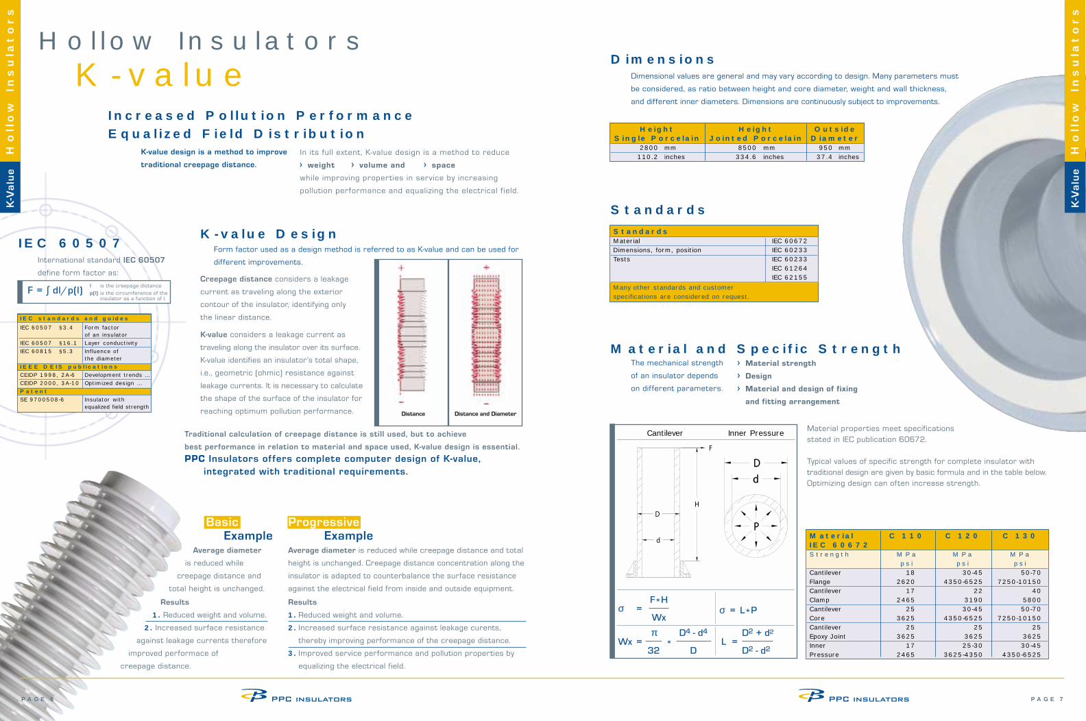
Hollow InsulatorsK-value
Increased Pollution Performance Equalized Field Distribution
In its full extent, K-value design is a method to reduce
> weight > volume and > space
while improving properties in service by increasing
pollution performance and equalizing the electrical f ield.
International standard IEC 60507
define form factor as:
K-value DesignForm factor used as a design method is referred to as K-value and can be used for
different improvements.
F = ∫ dl/p(l)Creepage distance considers a leakage
current as traveling along the exterior
contour of the insulator, identifying only
the linear distance.
K-value considers a leakage current as
traveling along the insulator over its surface.
K-value identifies an insulator’s total shape,
i.e., geometric (ohmic) resistance against
leakage currents. It is necessary to calculate
the shape of the surface of the insulator for
reaching optimum pollution performance.
Hollow
Insula
tors
IEC 60507
Dimensions
Standards
Distance Distance and Diameter
F*Hσ =
Wxσ = L*P
π D4 - d4
Wx = *32 D
D2 + d2
L =D2 - d2
Cantilever Inner Pressure
IEC standards and guidesIEC 60507 §3.4 Form factor
of an insulatorIEC 60507 §16.1 Layer conductivityIEC 60815 §5.3 Influence of
the diameterIEEE DEIS publicationsCEIDP 1998, 2A-6 Development trends …CEIDP 2000, 3A-10 Optimized design …PatentSE 9700508-6 Insulator with
equalized field strength
K-value design is a method to improve
traditional creepage distance.
Results
1. Reduced weight and volume.
2. Increased surface resistance
against leakage currents therefore
improved performace of
creepage distance.
Average diameter is reduced while creepage distance and total
height is unchanged. Creepage distance concentration along the
insulator is adapted to counterbalance the surface resistance
against the electrical field from inside and outside equipment.
Results
1. Reduced weight and volume.
2. Increased surface resistance against leakage curents,
thereby improving performance of the creepage distance.
3. Improved service performance and pollution properties by
equalizing the electrical field.
l is the creepage distance
p(l) is the circumference of the insulator as a function of l.
Traditional calculation of creepage distance is still used, but to achieve
best performance in relation to material and space used, K-value design is essential.
PPC Insulators offers complete computer design of K-value, integrated with traditional requirements.
Progressive Example
Average diameter
is reduced while
creepage distance and
total height is unchanged.
The mechanical strength
of an insulator depends
on different parameters.
> Material strength
> Design
> Material and design of fixing
and fitting arrangement
Height Height Outside Single Porcelain Jointed Porcelain Diameter
2800 mm 8500 mm 950 mm110.2 inches 334.6 inches 37.4 inches
Material properties meet specifications stated in IEC publication 60672.
Typical values of specific strength for complete insulator withtraditional design are given by basic formula and in the table below. Optimizing design can often increase strength.
Basic Example Material C 110 C 120 C 130
IEC 60672 Strength MPa MPa MPa
psi psi psiCantilever 18 30-45 50-70Flange 2620 4350-6525 7250-10150Cantilever 17 22 40Clamp 2465 3190 5800Cantilever 25 30-45 50-70Core 3625 4350-6525 7250-10150Cantilever 25 25 25Epoxy Joint 3625 3625 3625Inner 17 25-30 30-45Pressure 2465 3625-4350 4350-6525
Hollow
Insula
tors
K-V
alu
e
K-V
alu
e
StandardsMaterial IEC 60672Dimensions, form, position IEC 60233Tests IEC 60233
IEC 61264IEC 62155
Many other standards and customer specifications are considered on request.
Material and Specific Strength
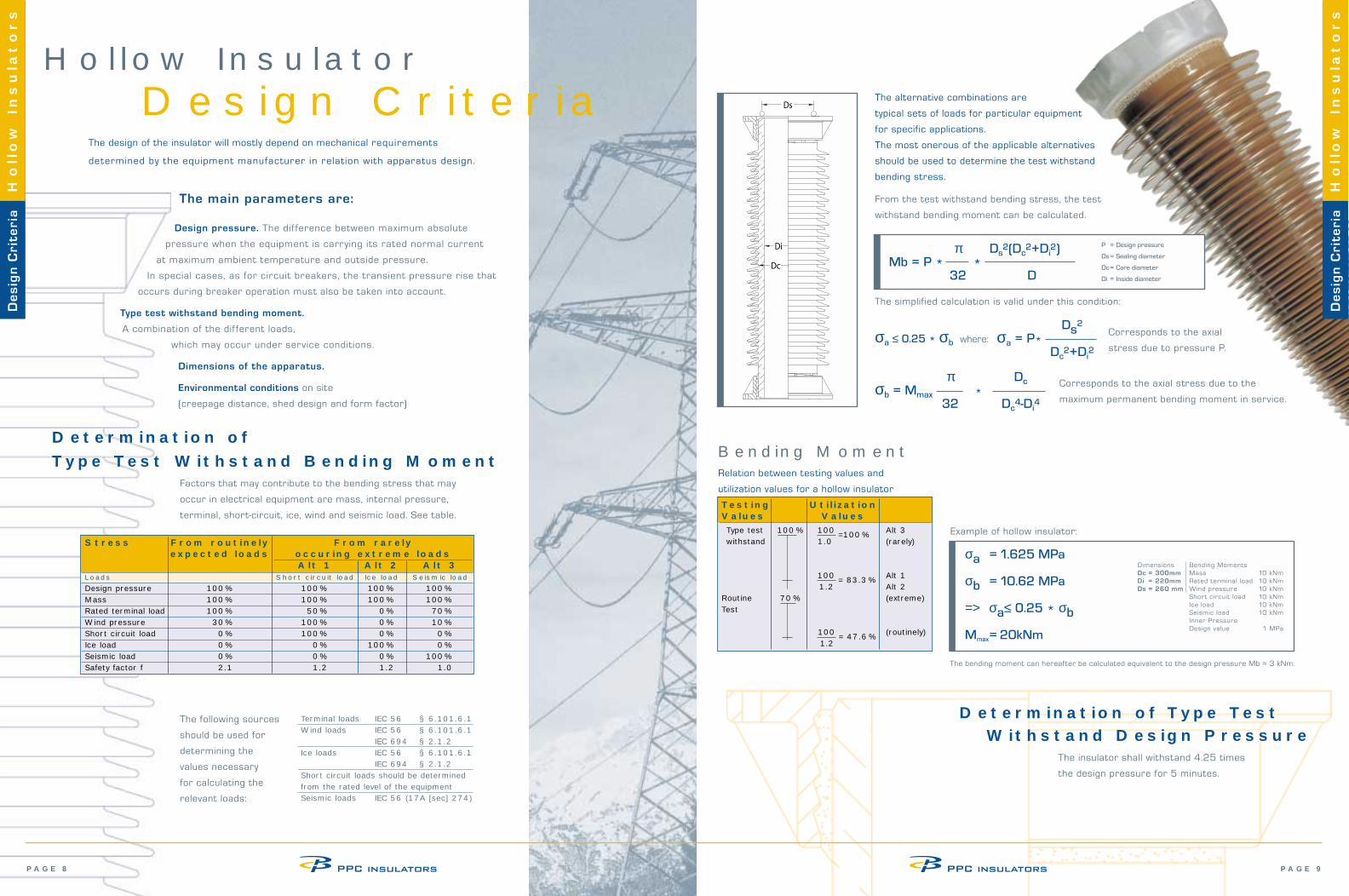
The design of the insulator will mostly depend on mechanical requirements
determined by the equipment manufacturer in relation with apparatus design.
The main parameters are:
Design pressure. The dif ference between maximum absolute
pressure when the equipment is carrying its rated normal current
at maximum ambient temperature and outside pressure.
In special cases, as for circuit breakers, the transient pressure rise that
occurs during breaker operation must also be taken into account.
Type test withstand bending moment.
A combination of the dif ferent loads,
which may occur under service conditions.
Dimensions of the apparatus.
Environmental conditions on site
(creepage distance, shed design and form factor)
Determination of Type Test Withstand Bending Moment
The alternative combinations are
typical sets of loads for particular equipment
for specific applications.
The most onerous of the applicable alternatives
should be used to determine the test withstand
bending stress.
From the test withstand bending stress, the test
withstand bending moment can be calculated.
Terminal loads IEC 56 § 6.101.6.1Wind loads IEC 56 § 6.101.6.1
IEC 694 § 2.1.2Ice loads IEC 56 § 6.101.6.1
IEC 694 § 2.1.2Short circuit loads should be determined from the rated level of the equipmentSeismic loads IEC 56 (17A [sec] 274)
Factors that may contribute to the bending stress that may
occur in electrical equipment are mass, internal pressure,
terminal, short-circuit, ice, wind and seismic load. See table.
PAGE 9PAGE 8
Hollow
Insula
tors
De
sig
n C
rite
ria
Hollow
Insula
tors
Stress From routinely From rarelyexpected loads occuring extreme loads
Alt 1 Alt 2 Alt 3Loads Short circuit load Ice load Seismic load
Design pressure 100 % 100 % 100 % 100 %Mass 100 % 100 % 100 % 100 %Rated terminal load 100 % 50 % 0 % 70 %Wind pressure 30 % 100 % 0 % 10 %Short circuit load 0 % 100 % 0 % 0 %Ice load 0 % 0 % 100 % 0 %Seismic load 0 % 0 % 0 % 100 %Safety factor f 2.1 1.2 1.2 1.0
Bending MomentRelation between testing values and
utilization values for a hollow insulator
σa = 1.625 MPa
σb = 10.62 MPa
=> σa≤ 0.25 * σb
Mmax= 20kNm
The following sources
should be used for
determining the
values necessary
for calculating the
relevant loads:
Hollow InsulatorDesign Criteria
Dimensions Bending MomentsDc = 300mm Mass 10 kNmDi = 220mm Rated terminal load 10 kNmDs = 260 mm Wind pressure 10 kNm
Short circuit load 10 kNmIce load 10 kNmSeismic load 10 kNmInner PressureDesign value 1 MPa
π Ds2(Dc
2+Di2)
Mb = P * *32 D
P = Design pressure
Ds= Sealing diameter
Dc= Core diameter
Di = Inside diameter
The simplified calculation is valid under this condition:
σa ≤ 0.25 * σb where:Ds
2
σa = P*Dc
2+Di2
Corresponds to the axial
stress due to pressure P.
π Dcσb = Mmax *
32 Dc4-Di
4
Corresponds to the axial stress due to the
maximum permanent bending moment in service.
Determination of Type Test Withstand Design Pressure
The insulator shall withstand 4.25 times
the design pressure for 5 minutes.
Example of hollow insulator:
Testing UtilizationValues ValuesType test 100 % 100 =100 % Alt 3withstand 1.0 (rarely)
100 = 83.3 % Alt 11.2 Alt 2
Routine 70 % (extreme)Test
100 = 47.6 % (routinely)1.2
The bending moment can hereafter be calculated equivalent to the design pressure Mb ≈ 3 kNm.
De
sig
n C
rite
ria
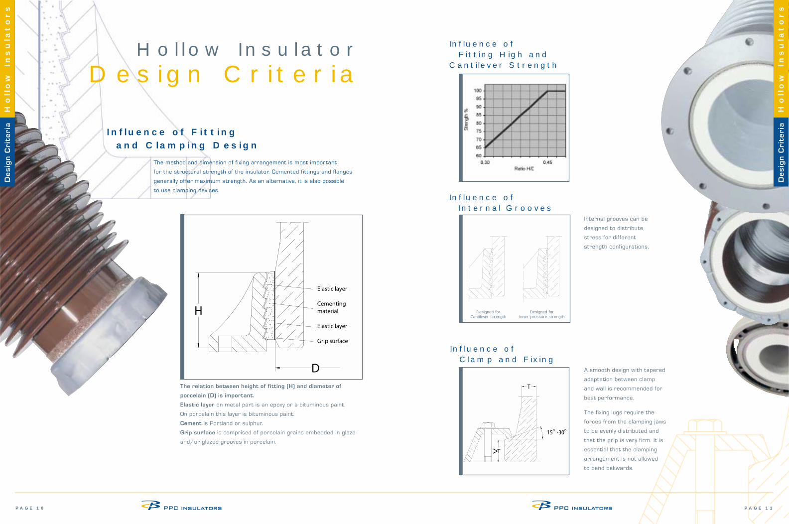
The method and dimension of fixing arrangement is most important
for the structural strength of the insulator. Cemented fittings and flanges
generally offer maximum strength. As an alternative, it is also possible
to use clamping devices.
Influence of Fitting and Clamping Design
The relation between height of fitting (H) and diameter of
porcelain (D) is important.
Elastic layer on metal part is an epoxy or a bituminous paint.
On porcelain this layer is bituminous paint.
Cement is Portland or sulphur.
Grip surface is comprised of porcelain grains embedded in glaze
and/or glazed grooves in porcelain.
Influence of Fitting High and
Cantilever Strength
Influence of Internal Grooves
Influence of Clamp and Fixing
PAGE 11PAGE 10
Designed for Cantilever strength
Designed for Inner pressure strength
Internal grooves can be
designed to distribute
stress for different
strength configurations.
A smooth design with tapered
adaptation between clamp
and wall is recommended for
best performance.
The fixing lugs require the
forces from the clamping jaws
to be evenly distributed and
that the grip is very firm. It is
essential that the clamping
arrangement is not allowed
to bend bakwards.
De
sig
n C
rite
ria
Hollow
Insula
tors
De
sig
n C
rite
ria
Hollow
Insula
tors
Hollow InsulatorDesign Criteria
Hollow InsulatorsPollution Performance
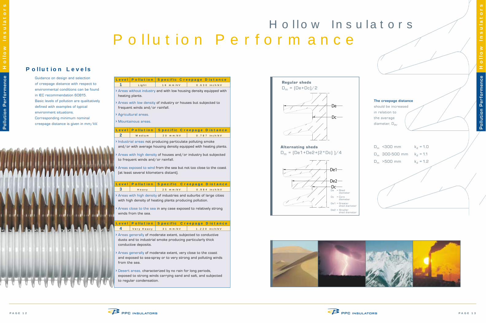
Pollution LevelsGuidance on design and selection
of creepage distance with respect to
environmental conditions can be found
in IEC recommendation 60815.
Basic levels of pollution are qualitatively
defined with examples of typical
environment situations.
Corresponding minimum nominal
creepage distance is given in mm/kV.
PAGE 13PAGE 12
Po
llu
tio
n P
erf
orm
en
ce
Hollow
Insula
tors
Po
llu
tio
n P
erf
orm
en
ce
Hollow
Insula
tors
Regular sheds
Dm = (De+Dc)/2
Alternating sheds
Dm = (De1+De2+(2*Dc) )/4
De = Shed diameter
Dc = Core diameter
De1 = Greater shed diameter
De2 = Smaller shed diameter
The creepage distance
should be increased
in relation to
the average
diameter, Dm.
Dm <300 mm kd = 1.0
Dm 300-500 mm kd = 1.1
Dm >500 mm kd = 1.2
> Areas generally of moderate extent, subjected to conductive dusts and to industrial smoke producing particularly thick conductive deposits.
> Areas generally of moderate extent, very close to the coast and exposed to sea-spray or to very strong and polluting winds from the sea.
> Desert areas, characterized by no rain for long periods, exposed to strong winds carrying sand and salt, and subjected to regular condensation.
> Areas without industry and with low housing density equipped withheating plants.
> Areas with low density of industry or houses but subjected to frequent winds and/or rainfall.
> Agricultural areas.
> Mountainous areas.
> Industrial areas not producing particulate polluting smoke and/or with average housing density equipped with heating plants.
> Areas with high density of houses and/or industry but subjected to frequent winds and/or rainfall.
> Areas exposed to wind from the sea but not too close to the coast (at least several kilometers distant).
> Areas with high density of industries and suburbs of large cities with high density of heating plants producing pollution.
> Areas close to the sea in any case exposed to relatively strong winds from the sea.
Level Pollution Specific Creepage Distance1 Light 16 mm/kV 0.630 inch/kV
Level Pollution Specific Creepage Distance2 Medium 20 mm/kV 0.787 inch/kV
Level Pollution Specific Creepage Distance3 Heavy 25 mm/kV 0.984 inch/kV
Level Pollution Specific Creepage Distance4 Very Heavy 31 mm/kV 1.220 inch/kV
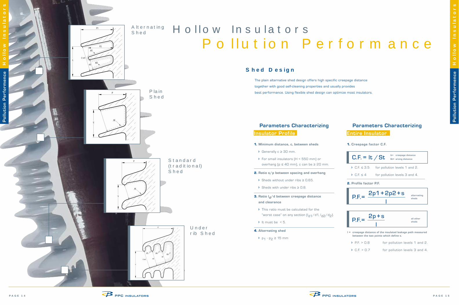
The plain alternative shed design offers high specific creepage distance
together with good self-cleaning properties and usually provides
best performance. Using flexible shed design can optimize most insulators.
Hollow InsulatorsPo llution Performance
Shed Design
Parameters Characterizing
Insulator Profile
Parameters Characterizing
Entire Insulator
1. Creepage factor C.F.
lt= creepage distance
St= arcing distanceC.F. = lt / St
> P.F. > 0.8 for pollution levels 1 and 2.
> C.F. > 0.7 for pollution levels 3 and 4.
2p + s P.F.=
lall other sheds
l = creepage distance of the insulated leakage path measured between the two points which define s.
Standard(traditional) Shed
AlternatingShed
Under rib Shed
Po
llu
tio
n P
erf
orm
en
ce
Hollow
Insula
tors
Po
llu
tio
n P
erf
orm
en
ce
Hollow
Insula
tors
alternating sheds
2p1+2p2+sP.F.=
l
1. Minimum distance, c, between sheds
> Generally c ≥ 30 mm.
> For small insulators (H < 550 mm) or
overhang (p ≤ 40 mm), c can be ≥ 20 mm.
2. Ratio s/p between spacing and overhang
> Sheds without under ribs ≥ 0.65.
> Sheds with under ribs ≥ 0.8.
3. Ratio ld/d between creepage distance
and clearance
> This ratio must be calculated for the
“worst case” on any section (ld1/d1, ld2/d2).
> It must be < 5.
4. Alternating shed
> p1 - p2 ≥ 15 mm
> C.F. ≤ 3.5 for pollution levels 1 and 2.
> C.F. ≤ 4 for pollution levels 3 and 4.
2. Profile factor P.F.
PlainShed
PAGE 15PAGE 14
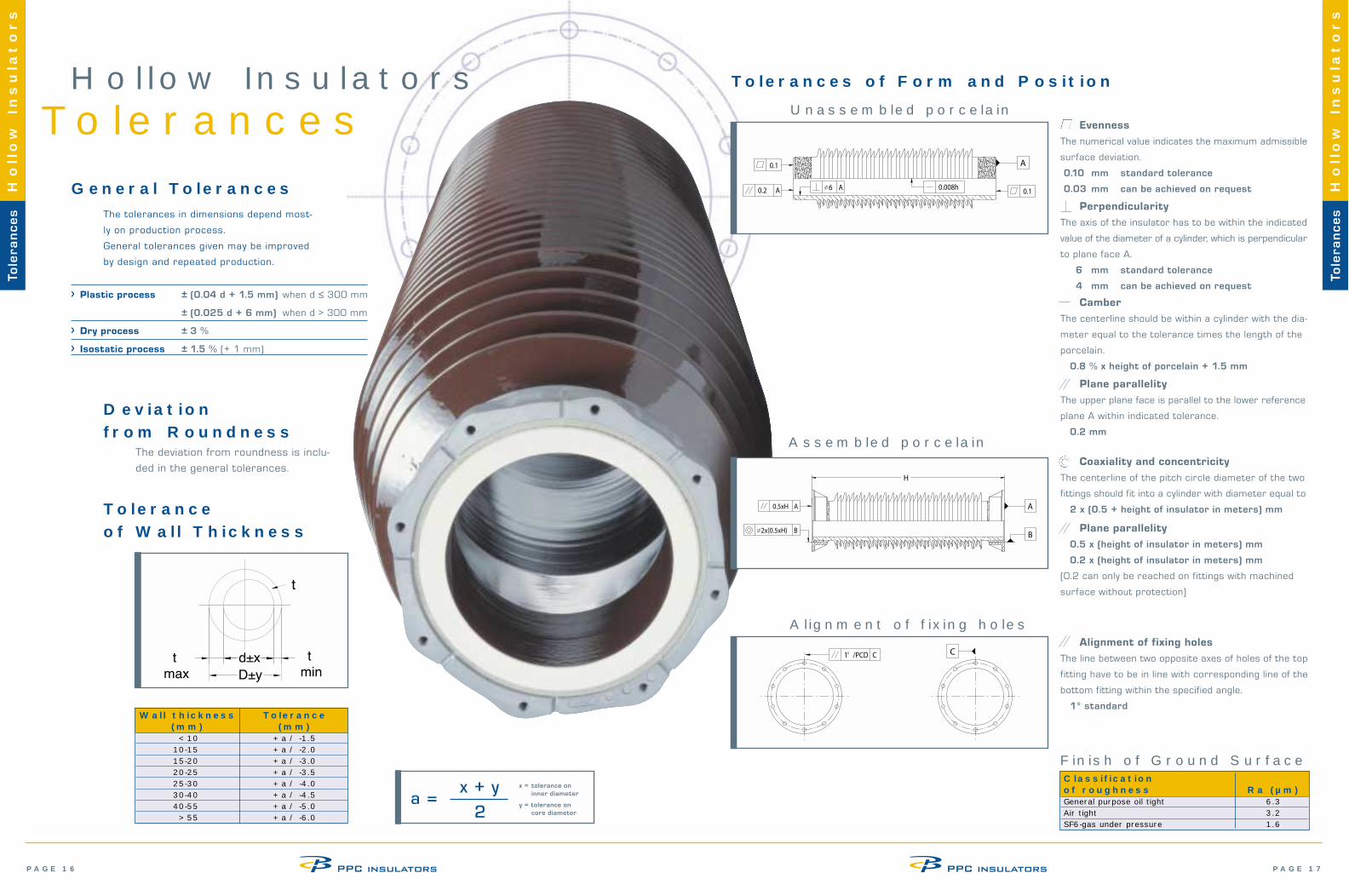
Coaxiality and concentricity
The centerline of the pitch circle diameter of the two
fittings should fit into a cylinder with diameter equal to
2 x (0.5 + height of insulator in meters) mm
PAGE 17PAGE 16
Hollow InsulatorsTolerances
General TolerancesThe tolerances in dimensions depend most-
ly on production process.
General tolerances given may be improved
by design and repeated production.
Tolerances of Form and Position
Plane parallelity
0.5 x (height of insulator in meters) mm
0.2 x (height of insulator in meters) mm
(0.2 can only be reached on fittings with machined
surface without protection)
Unassembled porcelain
Tole
ran
ce
sH
ollow
Insula
tors
Tole
ran
ce
sH
ollow
Insula
tors
Alignment of fixing holes
The line between two opposite axes of holes of the top
fitting have to be in line with corresponding line of the
bottom fitting within the specified angle.
1° standard
Alignment of fixing holes
Finish of Ground SurfaceClassification of roughness Ra (µm)General purpose oil tight 6.3Air tight 3.2SF6-gas under pressure 1.6
Camber
The centerline should be within a cylinder with the dia-
meter equal to the tolerance times the length of the
porcelain.
0.8 % x height of porcelain + 1.5 mm
Perpendicularity
The axis of the insulator has to be within the indicated
value of the diameter of a cylinder, which is perpendicular
to plane face A.
6 mm standard tolerance
4 mm can be achieved on request
Plane parallelity
The upper plane face is parallel to the lower reference
plane A within indicated tolerance.
0.2 mm
Evenness
The numerical value indicates the maximum admissible
surface deviation.
0.10 mm standard tolerance
0.03 mm can be achieved on request
> Plastic process ± (0.04 d + 1.5 mm) when d ≤ 300 mm
± (0.025 d + 6 mm) when d > 300 mm
> Dry process ± 3 %
> Isostatic process ± 1.5 % (+ 1 mm)
Deviation from Roundness
Wall thickness Tolerance (mm) (mm)
< 10 + a / -1.510-15 + a / -2.015-20 + a / -3.020-25 + a / -3.525-30 + a / -4.030-40 + a / -4.540-55 + a / -5.0
> 55 + a / -6.0
x + y a =
2
x = tolerance on inner diameter
y = tolerance on core diameter
The deviation from roundness is inclu-
ded in the general tolerances.
Tolerance of Wall Thickness
Assembled porcelain
D±y
t
mind±xt
max
t
PAGE 19PAGE 18
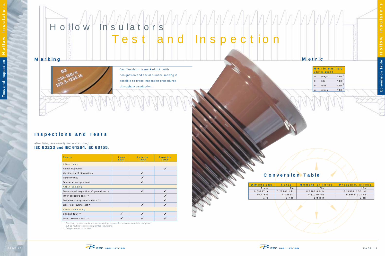
Conversion Table
Tes
t a
nd
In
sp
ec
tio
nH
ollow
Insula
tors
Co
nve
rsio
n T
ab
leH
ollow
Insula
tors
Dimensions Force Moment of Force Pressure, stress1 mm 1N 1 Nm 1Pa
0.03937 in 0.22481 ft lb 8.8508 ft lb in 0.14504*10-3 psi25.4 mm 4.4482N 0.11299 Nm 6.8948*103 Pa
1 in 1 ft lb 1 ft lb in 1 psi
Metric
Metric multiple units used
M mega *106
k kilo *103
m milli *10-3
µ micro *10-6
Each insulator is marked both with
designation and serial number, making it
possible to trace inspection procedures
throughout production.
Marking
Tests Type Sample Routine test test test
After firing
Visual inspection ✓
Verification of dimensions ✓
Porosity test ✓
Temperature cycle test ✓
After grinding
Dimensional inspection of ground parts ✓ ✓
Inner pressure test ** ✓
Dye check on ground surface ** ✓
Electrical routine test * ✓ ✓
After cementing
Bending test ** ✓ ✓ ✓
Inner pressure test ** ✓ ✓ ✓
* Electrical routine test is only performed on request for insulators made in one piece, but as routine test on epoxy jointed insulators.
** Only performed on request.
af ter f iring are usually made according to
IEC 60233 and IEC 61264, IEC 62155.
Inspections and Tests
Hollow InsulatorsTest and Inspection