Embed Size (px)
Citation preview
14
A.C medium voltage network protection10 kA arrester - Class 2
AZC series General characteristics
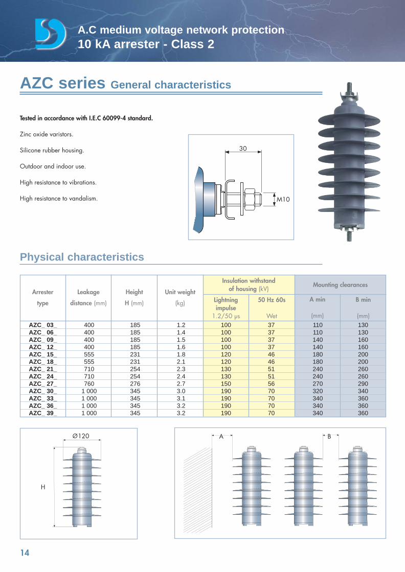
Tested in accordance with I.E.C 60099-4 standard.
Zinc oxide varistors.
Silicone rubber housing.
Outdoor and indoor use.
High resistance to vibrations.
High resistance to vandalism.
Physical characteristics
Arrester
type
Leakage
distance (mm)
Height
H (mm)
Unit weight
(kg) Lightningimpulse
1.2/50 µs
50 Hz 60s
Wet
A min
(mm)
B min
(mm)
Insulation withstandof housing (kV)
Mounting clearances
AZC_ 03_ 400 185 1.2 100 37 110 130AZC_ 06_ 400 185 1.4 100 37 110 130AZC_ 09_ 400 185 1.5 100 37 140 160AZC_ 12_ 400 185 1.6 100 37 140 160AZC_ 15_ 555 231 1.8 120 46 180 200AZC_ 18_ 555 231 2.1 120 46 180 200AZC_ 21_ 710 254 2.3 130 51 240 260AZC_ 24_ 710 254 2.4 130 51 240 260AZC_ 27_ 760 276 2.7 150 56 270 290AZC_ 30_ 1 000 345 3.0 190 70 320 340AZC_ 33_ 1 000 345 3.1 190 70 340 360AZC_ 36_ 1 000 345 3.2 190 70 340 360AZC_ 39_ 1 000 345 3.2 190 70 340 360
A B
H
120
30
M10
catalogue Dervasil 30/05/08 16:36 Page 14
15
A.C medium voltage network protection10 kA arrester - Class 2
Nominal discharge current: 10 kA 8/20 µs impulseLine discharge class: 2High current withstand: 2 x 100 kA 4/10µs impulsesLong duration current withstand: 18 x 500 A 2000 µs impulses
Energy absorption capacity 5.5 kJoule/kV of Uc for 2 x 2000 µs impulses4.6 kJoule/kV of Uc for one 4/10 µs impulse
Rated frequency 48 to 62 HzService temperature - 40°C to + 40°C (+ 60°C short duration)Specified continuous load (SCL) 100 N.mSpecified short term load (SSL) 250 N.mMax tension strength 1 kNMax torsion strength 30 N.mPollution area I.E.C 60815 3Short circuit rating after over voltage failure as Appendix 0 of I.E.C 60099-4 20000 A for 0.2s / 600 A for 1s
0
0,1
0,2
0,3
0,4
0,5
0,6
0,7
0,8
0,9
1
1,1
1,2
1,3
1,4
1,5
1,6
0,1 1 10 100 1000 10000 100000
Preloaded Energy = max Capability
Preloaded Energy = 0
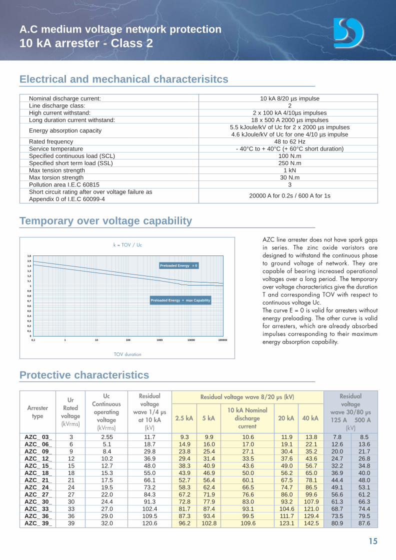
AZC line arrester does not have spark gapsin series. The zinc oxide varistors aredesigned to withstand the continuous phaseto ground voltage of network. They arecapable of bearing increased operationalvoltages over a long period. The temporaryover voltage characteristics give the durationT and corresponding TOV with respect tocontinuous voltage Uc. The curve E = 0 is valid for arresters withoutenergy preloading. The other curve is validfor arresters, which are already absorbedimpulses corresponding to their maximumenergy absorption capability.
AZC_ 03_ 3 2.55 11.7 9.3 9.9 10.6 11.9 13.8 7.8 8.5AZC_ 06_ 6 5.1 18.7 14.9 16.0 17.0 19.1 22.1 12.6 13.6AZC_ 09_ 9 8.4 29.8 23.8 25.4 27.1 30.4 35.2 20.0 21.7AZC_ 12_ 12 10.2 36.9 29.4 31.4 33.5 37.6 43.6 24.7 26.8AZC_ 15_ 15 12.7 48.0 38.3 40.9 43.6 49.0 56.7 32.2 34.8AZC_ 18_ 18 15.3 55.0 43.9 46.9 50.0 56.2 65.0 36.9 40.0AZC_ 21_ 21 17.5 66.1 52.7 56.4 60.1 67.5 78.1 44.4 48.0AZC_ 24_ 24 19.5 73.2 58.3 62.4 66.5 74.7 86.5 49.1 53.1AZC_ 27_ 27 22.0 84.3 67.2 71.9 76.6 86.0 99.6 56.6 61.2AZC_ 30_ 30 24.4 91.3 72.8 77.9 83.0 93.2 107.9 61.3 66.3AZC_ 33_ 33 27.0 102.4 81.7 87.4 93.1 104.6 121.0 68.7 74.4AZC_ 36_ 36 29.0 109.5 87.3 93.4 99.5 111.7 129.4 73.5 79.5 AZC_ 39_ 39 32.0 120.6 96.2 102.8 109.6 123.1 142.5 80.9 87.6
Electrical and mechanical characterisitcs
Temporary over voltage capability
Protective characteristics
Arrestertype
UrRated
voltage(kVrms)
UcContinuousoperatingvoltage(kVrms)
Residualvoltage
wave 1/4 µsat 10 kA
(kV)2.5 kA 5 kA
10 kA Nominaldischarge
current20 kA 40 kA
Residualvoltage
wave 30/80 µs125 A 500 A
(kV)
Residual voltage wave 8/20 µs (kV)
k = TOV / Uc
TOV duration
catalogue Dervasil 30/05/08 16:36 Page 15
Ur (kVrms)
Arrester referenceAZB--0
Arrester referenceAZC--0
3 6 9 12 15 18 21 24 27 30 33 36 39
AZB 030 AZB 060 AZB 090 AZB 120 AZB 150 AZB 180 AZB 210 AZB 240 AZB 270 AZB 300 AZB 330 AZB 360 AZB 390
AZC 030 AZC 060 AZC 090 AZC 120 AZC 150 AZC 180AZC 210 AZC 240 AZC 270 AZC 300 AZC 330 AZC 360 AZC 390
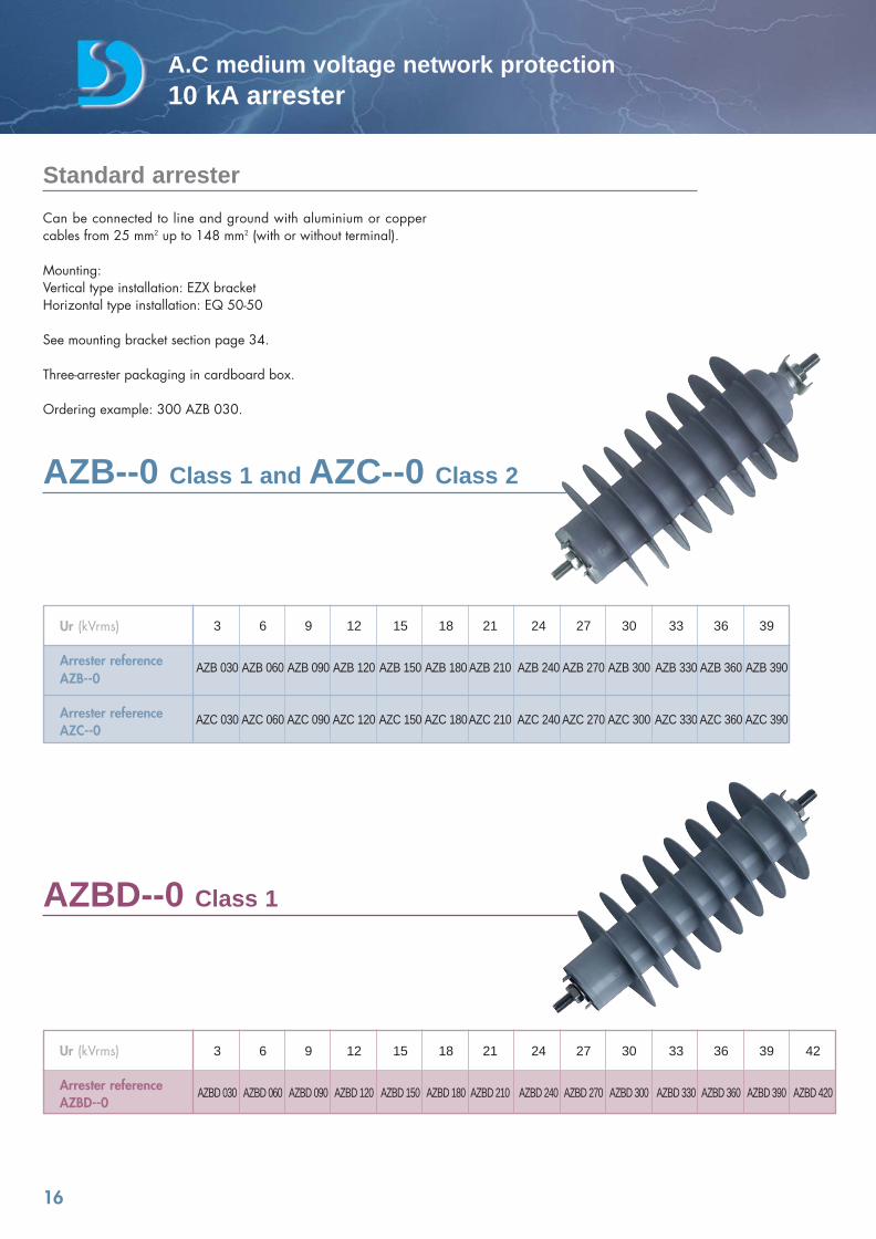
AZB--0 Class 1 and AZC--0 Class 2
16
A.C medium voltage network protection10 kA arrester
Can be connected to line and ground with aluminium or coppercables from 25 mm2 up to 148 mm2 (with or without terminal).
Mounting:Vertical type installation: EZX bracketHorizontal type installation: EQ 50-50
See mounting bracket section page 34.
Three-arrester packaging in cardboard box.
Ordering example: 300 AZB 030.
AZBD--0 Class 1
Standard arrester
Ur (kVrms) 3 6 9 12 15 18 21 24 27 30 33 36 39 42
Arrester reference AZBD 030 AZBD 060 AZBD 090 AZBD 120 AZBD 150 AZBD 180 AZBD 210 AZBD 240 AZBD 270 AZBD 300 AZBD 330 AZBD 360 AZBD 390 AZBD 420AZBD--0
catalogue Dervasil 30/05/08 16:36 Page 16
Ur (kVrms) 3 6 9 12 15 18 21 24 27 30 33 36 39 42
Arrester reference AZBD 031 AZBD 061 AZBD 091 AZBD 121 AZBD 151 AZBD 181 AZBD 211 AZBD 241 AZBD 271 AZBD 301 AZBD 331 AZBD 361 AZBD 391 AZBD 421AZBD--1
17
A.C medium voltage network protection10 kA arrester
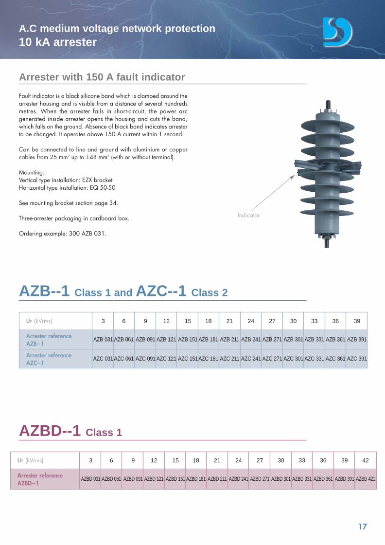
Fault indicator is a black silicone band which is clamped around thearrester housing and is visible from a distance of several hundredsmetres. When the arrester fails in short-circuit, the power arcgenerated inside arrester opens the housing and cuts the band,which falls on the ground. Absence of black band indicates arresterto be changed. It operates above 150 A current within 1 second.
Can be connected to line and ground with aluminium or coppercables from 25 mm2 up to 148 mm2 (with or without terminal).
Mounting:Vertical type installation: EZX bracketHorizontal type installation: EQ 50-50
See mounting bracket section page 34.
Three-arrester packaging in cardboard box.
Ordering example: 300 AZB 031.
Ur (kVrms) 3 6 9 12 15 18 21 24 27 30 33 36 39
Arrester reference AZB 031 AZB 061 AZB 091 AZB 121 AZB 151 AZB 181 AZB 211 AZB 241 AZB 271 AZB 301 AZB 331 AZB 361 AZB 391AZB--1
Arrester reference AZC 031 AZC 061 AZC 091 AZC 121 AZC 151AZC 181 AZC 211 AZC 241 AZC 271 AZC 301 AZC 331 AZC 361 AZC 391AZC--1
Indicator
AZB--1 Class 1 and AZC--1 Class 2
AZBD--1 Class 1
Arrester with 150 A fault indicator
catalogue Dervasil 30/05/08 16:36 Page 17
18
A.C medium voltage network protection10 kA arrester
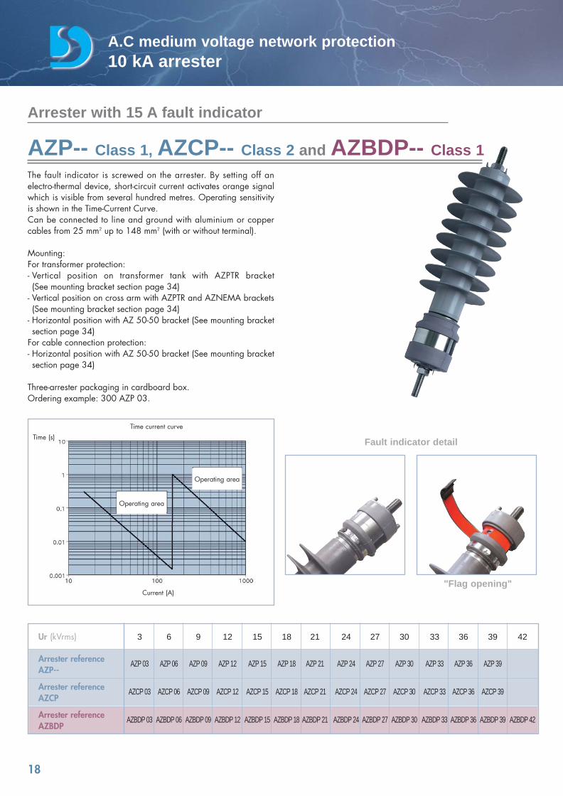
The fault indicator is screwed on the arrester. By setting off anelectro-thermal device, short-circuit current activates orange signalwhich is visible from several hundred metres. Operating sensitivityis shown in the Time-Current Curve.Can be connected to line and ground with aluminium or coppercables from 25 mm2 up to 148 mm2 (with or without terminal).
Mounting:For transformer protection:- Vertical position on transformer tank with AZPTR bracket (See mounting bracket section page 34)
- Vertical position on cross arm with AZPTR and AZNEMA brackets(See mounting bracket section page 34)
- Horizontal position with AZ 50-50 bracket (See mounting bracketsection page 34)
For cable connection protection:- Horizontal position with AZ 50-50 bracket (See mounting bracketsection page 34)
Three-arrester packaging in cardboard box.Ordering example: 300 AZP 03.
Time (s)Time current curve
Current (A)
Fault indicator detail
"Flag opening"
Operating area
Operating area
Arrester with 15 A fault indicator
AZP-- Class 1, AZCP-- Class 2 and AZBDP-- Class 1
Ur (kVrms) 3 6 9 12 15 18 21 24 27 30 33 36 39 42
Arrester reference AZP 03 AZP 06 AZP 09 AZP 12 AZP 15 AZP 18 AZP 21 AZP 24 AZP 27 AZP 30 AZP 33 AZP 36 AZP 39AZP--
Arrester reference AZCP 03 AZCP 06 AZCP 09 AZCP 12 AZCP 15 AZCP 18 AZCP 21 AZCP 24 AZCP 27 AZCP 30 AZCP 33 AZCP 36 AZCP 39AZCP
Arrester reference AZBDP 03 AZBDP 06 AZBDP 09 AZBDP 12 AZBDP 15 AZBDP 18 AZBDP 21 AZBDP 24 AZBDP 27 AZBDP 30 AZBDP 33 AZBDP 36 AZBDP 39 AZBDP 42AZBDP
catalogue Dervasil 30/05/08 16:36 Page 18
19
A.C medium voltage network protection10 kA arrester
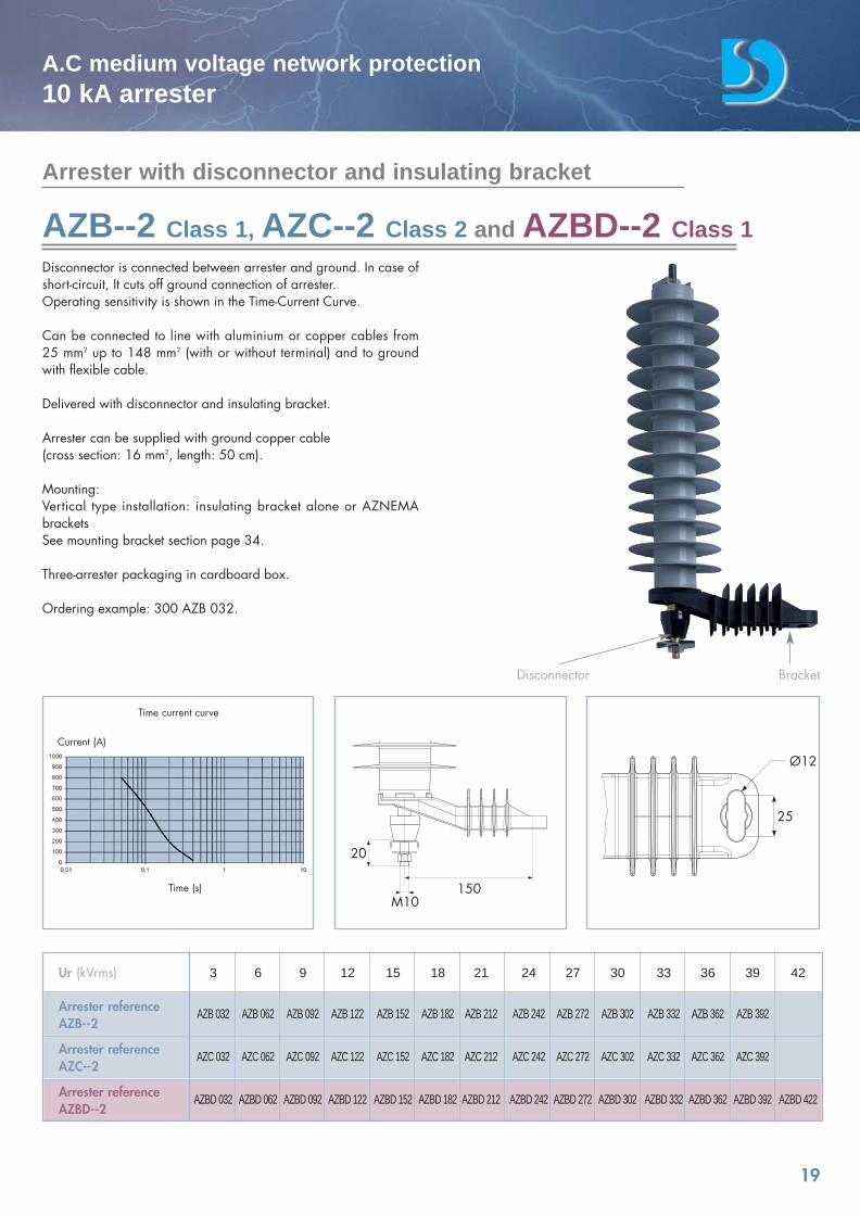
Disconnector is connected between arrester and ground. In case ofshort-circuit, It cuts off ground connection of arrester.Operating sensitivity is shown in the Time-Current Curve.
Can be connected to line with aluminium or copper cables from 25 mm2 up to 148 mm2 (with or without terminal) and to groundwith flexible cable.
Delivered with disconnector and insulating bracket.
Arrester can be supplied with ground copper cable (cross section: 16 mm2, length: 50 cm).
Mounting:Vertical type installation: insulating bracket alone or AZNEMAbracketsSee mounting bracket section page 34.
Three-arrester packaging in cardboard box.
Ordering example: 300 AZB 032.
150
25
Ø12
Disconnector Bracket
Time current curve
Time (s)
Current (A)
Arrester with disconnector and insulating bracket
AZB--2 Class 1, AZC--2 Class 2 and AZBD--2 Class 1
Ur (kVrms) 3 6 9 12 15 18 21 24 27 30 33 36 39 42
Arrester reference AZB 032 AZB 062 AZB 092 AZB 122 AZB 152 AZB 182 AZB 212 AZB 242 AZB 272 AZB 302 AZB 332 AZB 362 AZB 392AZB--2
Arrester reference AZC 032 AZC 062 AZC 092 AZC 122 AZC 152 AZC 182 AZC 212 AZC 242 AZC 272 AZC 302 AZC 332 AZC 362 AZC 392AZC--2
Arrester reference AZBD 032 AZBD 062 AZBD 092 AZBD 122 AZBD 152 AZBD 182 AZBD 212 AZBD 242 AZBD 272 AZBD 302 AZBD 332 AZBD 362 AZBD 392 AZBD 422AZBD--2
M10
20
catalogue Dervasil 30/05/08 16:36 Page 19
20
A.C medium voltage network protection10 kA arrester
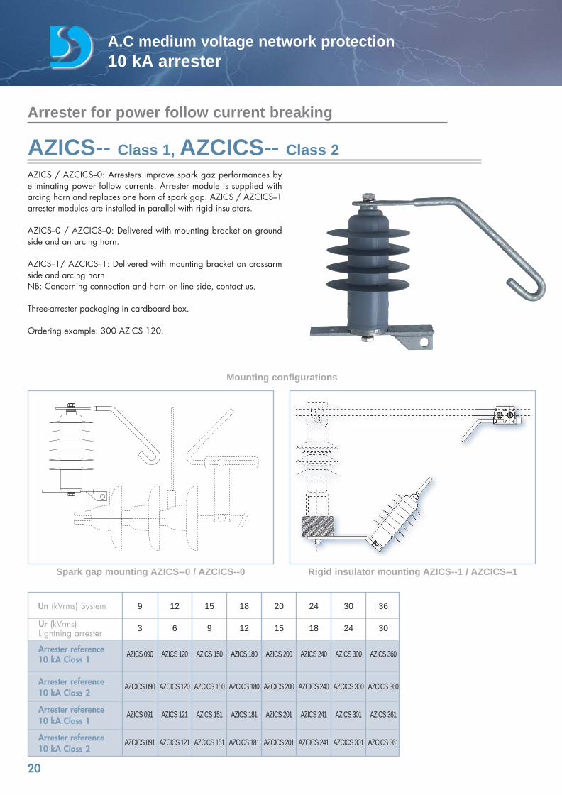
AZICS / AZCICS--0: Arresters improve spark gaz performances byeliminating power follow currents. Arrester module is supplied witharcing horn and replaces one horn of spark gap. AZICS / AZCICS--1arrester modules are installed in parallel with rigid insulators.
AZICS--0 / AZCICS--0: Delivered with mounting bracket on groundside and an arcing horn.
AZICS--1/ AZCICS--1: Delivered with mounting bracket on crossarmside and arcing horn.NB: Concerning connection and horn on line side, contact us.
Three-arrester packaging in cardboard box.
Ordering example: 300 AZICS 120.
Arrester for power follow current breaking
AZICS-- Class 1, AZCICS-- Class 2
Mounting configurations
Spark gap mounting AZICS--0 / AZCICS--0 Rigid insulator mounting AZICS--1 / AZCICS--1
Un (kVrms) System 9 12 15 18 20 24 30 36
3 6 9 12 15 18 24 30
Arrester reference AZICS 090 AZICS 120 AZICS 150 AZICS 180 AZICS 200 AZICS 240 AZICS 300 AZICS 36010 kA Class 1
Arrester reference AZCICS 090 AZCICS 120 AZCICS 150 AZCICS 180 AZCICS 200 AZCICS 240 AZCICS 300 AZCICS 36010 kA Class 2
Arrester reference AZICS 091 AZICS 121 AZICS 151 AZICS 181 AZICS 201 AZICS 241 AZICS 301 AZICS 36110 kA Class 1
Arrester reference AZCICS 091 AZCICS 121 AZCICS 151 AZCICS 181 AZCICS 201 AZCICS 241 AZCICS 301 AZCICS 36110 kA Class 2
Ur (kVrms) Lightning arrester
catalogue Dervasil 30/05/08 16:36 Page 20
A.C medium voltagenetwork protection
A.C
med
ium
vol
tage
net
wor
k pr
otec
tion
5kA
arre
ster
5 kA arresterEZB seriesEZBD series
General characteristics EZB, EZBD 22
Standard arrester EZB--0, EZBD--0 26
Arrester with 150 A fault indicator EZB--1, EZBD--1 27
Arrester with disconnector EZB--2, EZBD--2 28
catalogue Dervasil 30/05/08 16:36 Page 21
22
A.C medium voltage network protection5 kA arrester
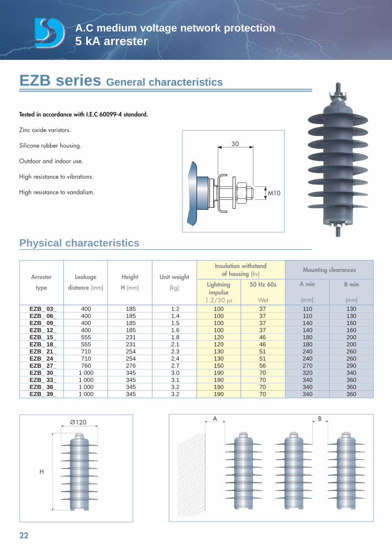
Tested in accordance with I.E.C 60099-4 standard.
Zinc oxide varistors.
Silicone rubber housing.
Outdoor and indoor use.
High resistance to vibrations.
High resistance to vandalism.
EZB series General characteristics
Physical characteristics
Arrester
type
Leakage
distance (mm)
Height
H (mm)
Unit weight
(kg) Lightningimpulse
1.2/50 µs
50 Hz 60s
Wet
A min
(mm)
B min
(mm)
Insulation withstandof housing (kv)
Mounting clearances
EZB_ 03_ 400 185 1.2 100 37 110 130EZB_ 06_ 400 185 1.4 100 37 110 130EZB_ 09_ 400 185 1.5 100 37 140 160EZB_ 12_ 400 185 1.6 100 37 140 160EZB_ 15_ 555 231 1.8 120 46 180 200EZB_ 18_ 555 231 2.1 120 46 180 200EZB_ 21_ 710 254 2.3 130 51 240 260EZB_ 24_ 710 254 2.4 130 51 240 260EZB_ 27_ 760 276 2.7 150 56 270 290EZB_ 30_ 1 000 345 3.0 190 70 320 340EZB_ 33_ 1 000 345 3.1 190 70 340 360EZB_ 36_ 1 000 345 3.2 190 70 340 360EZB_ 39_ 1 000 345 3.2 190 70 340 360
A B
H
120
30
M10
catalogue Dervasil 30/05/08 16:36 Page 22
23
A.C medium voltage network protection5 kA arrester
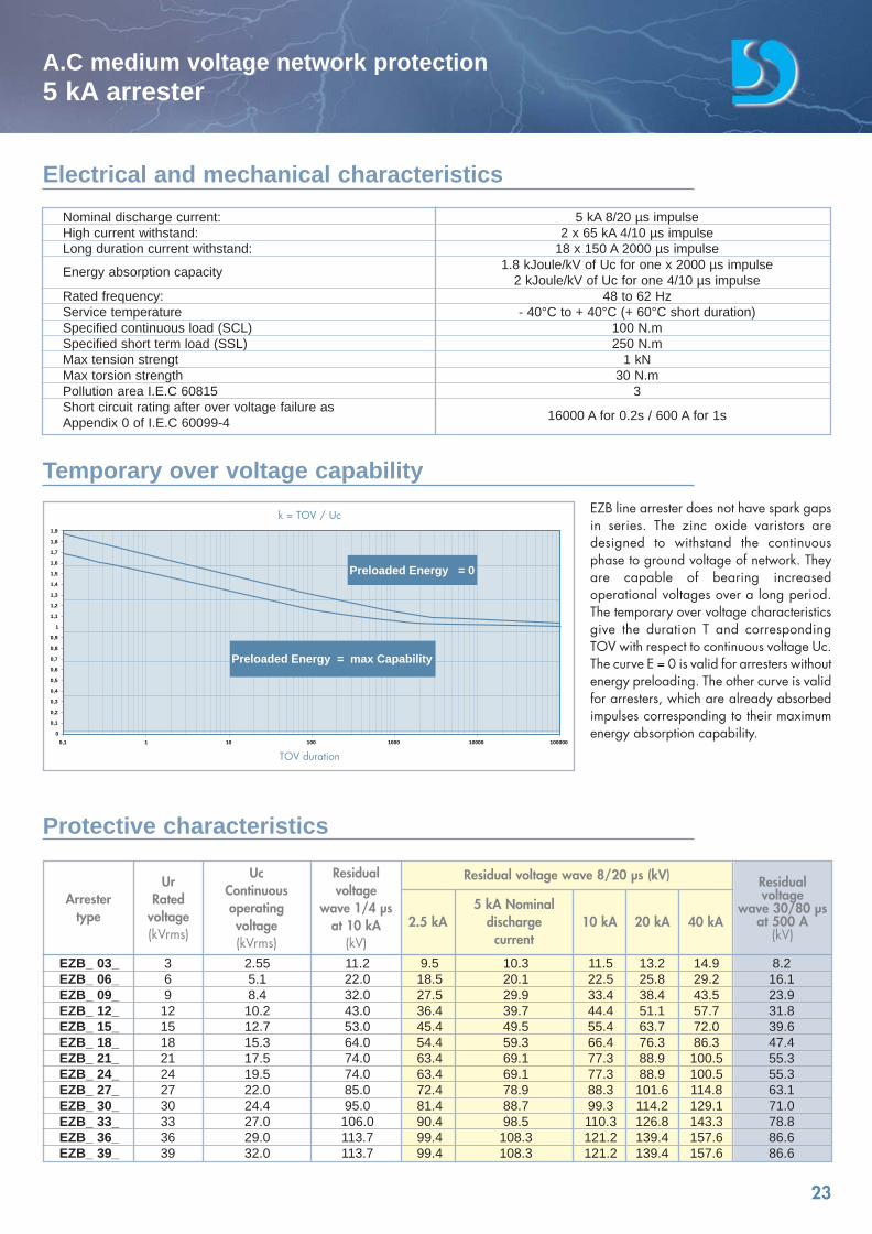
Nominal discharge current: 5 kA 8/20 µs impulseHigh current withstand: 2 x 65 kA 4/10 µs impulseLong duration current withstand: 18 x 150 A 2000 µs impulse
Energy absorption capacity 1.8 kJoule/kV of Uc for one x 2000 µs impulse 2 kJoule/kV of Uc for one 4/10 µs impulse
Rated frequency: 48 to 62 HzService temperature - 40°C to + 40°C (+ 60°C short duration)Specified continuous load (SCL) 100 N.mSpecified short term load (SSL) 250 N.mMax tension strengt 1 kNMax torsion strength 30 N.mPollution area I.E.C 60815 3Short circuit rating after over voltage failure as Appendix 0 of I.E.C 60099-4 16000 A for 0.2s / 600 A for 1s
EZB line arrester does not have spark gapsin series. The zinc oxide varistors aredesigned to withstand the continuousphase to ground voltage of network. Theyare capable of bearing increasedoperational voltages over a long period.The temporary over voltage characteristicsgive the duration T and correspondingTOV with respect to continuous voltage Uc. The curve E = 0 is valid for arresters withoutenergy preloading. The other curve is validfor arresters, which are already absorbedimpulses corresponding to their maximumenergy absorption capability.
EZB_ 03_ 3 2.55 11.2 9.5 10.3 11.5 13.2 14.9 8.2EZB_ 06_ 6 5.1 22.0 18.5 20.1 22.5 25.8 29.2 16.1EZB_ 09_ 9 8.4 32.0 27.5 29.9 33.4 38.4 43.5 23.9EZB_ 12_ 12 10.2 43.0 36.4 39.7 44.4 51.1 57.7 31.8EZB_ 15_ 15 12.7 53.0 45.4 49.5 55.4 63.7 72.0 39.6EZB_ 18_ 18 15.3 64.0 54.4 59.3 66.4 76.3 86.3 47.4EZB_ 21_ 21 17.5 74.0 63.4 69.1 77.3 88.9 100.5 55.3EZB_ 24_ 24 19.5 74.0 63.4 69.1 77.3 88.9 100.5 55.3EZB_ 27_ 27 22.0 85.0 72.4 78.9 88.3 101.6 114.8 63.1EZB_ 30_ 30 24.4 95.0 81.4 88.7 99.3 114.2 129.1 71.0EZB_ 33_ 33 27.0 106.0 90.4 98.5 110.3 126.8 143.3 78.8EZB_ 36_ 36 29.0 113.7 99.4 108.3 121.2 139.4 157.6 86.6EZB_ 39_ 39 32.0 113.7 99.4 108.3 121.2 139.4 157.6 86.6
Electrical and mechanical characteristics
Temporary over voltage capability
Protective characteristics
Arrestertype
UrRated
voltage(kVrms)
UcContinuousoperatingvoltage(kVrms)
Residualvoltage
wave 1/4 µsat 10 kA
(kV)2.5 kA 10 kA
5 kA Nominaldischarge
current20 kA 40 kA
Residualvoltage
wave 30/80 µsat 500 A
(kV)
Residual voltage wave 8/20 µs (kV)
0
0,1
0,2
0,3
0,4
0,5
0,6
0,7
0,8
0,9
1
1,1
1,2
1,3
1,4
1,5
1,6
1,7
1,8
1,9
0,1 1 10 100 1000 10000 100000
Preloaded Energy = max Capability
Preloaded Energy = 0
k = TOV / Uc
TOV duration
catalogue Dervasil 30/05/08 16:36 Page 23
24
A.C medium voltage network protection5 kA arrester
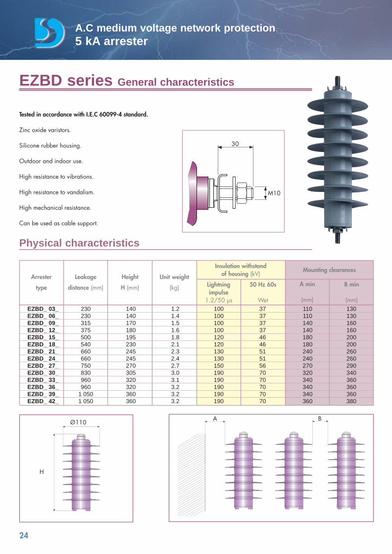
Tested in accordance with I.E.C 60099-4 standard.
Zinc oxide varistors.
Silicone rubber housing.
Outdoor and indoor use.
High resistance to vibrations.
High resistance to vandalism.
High mechanical resistance.
Can be used as cable support.
EZBD series General characteristics
Physical characteristics
Arrester
type
Leakage
distance (mm)
Height
H (mm)
Unit weight
(kg) Lightningimpulse
1.2/50 µs
50 Hz 60s
Wet
A min
(mm)
B min
(mm)
Insulation withstandof housing (kV)
Mounting clearances
EZBD_ 03_ 230 140 1.2 100 37 110 130EZBD_ 06_ 230 140 1.4 100 37 110 130EZBD_ 09_ 315 170 1.5 100 37 140 160EZBD_ 12_ 375 180 1.6 100 37 140 160EZBD_ 15_ 500 195 1.8 120 46 180 200EZBD_ 18_ 540 230 2.1 120 46 180 200EZBD_ 21_ 660 245 2.3 130 51 240 260EZBD_ 24_ 660 245 2.4 130 51 240 260EZBD_ 27_ 750 270 2.7 150 56 270 290EZBD_ 30_ 830 305 3.0 190 70 320 340EZBD_ 33_ 960 320 3.1 190 70 340 360EZBD_ 36_ 960 320 3.2 190 70 340 360EZBD_ 39_ 1 050 360 3.2 190 70 340 360EZBD_ 42_ 1 050 360 3.2 190 70 360 380
H
A B110
30
M10
catalogue Dervasil 30/05/08 16:36 Page 24
25
A.C medium voltage network protection5 kA arrester
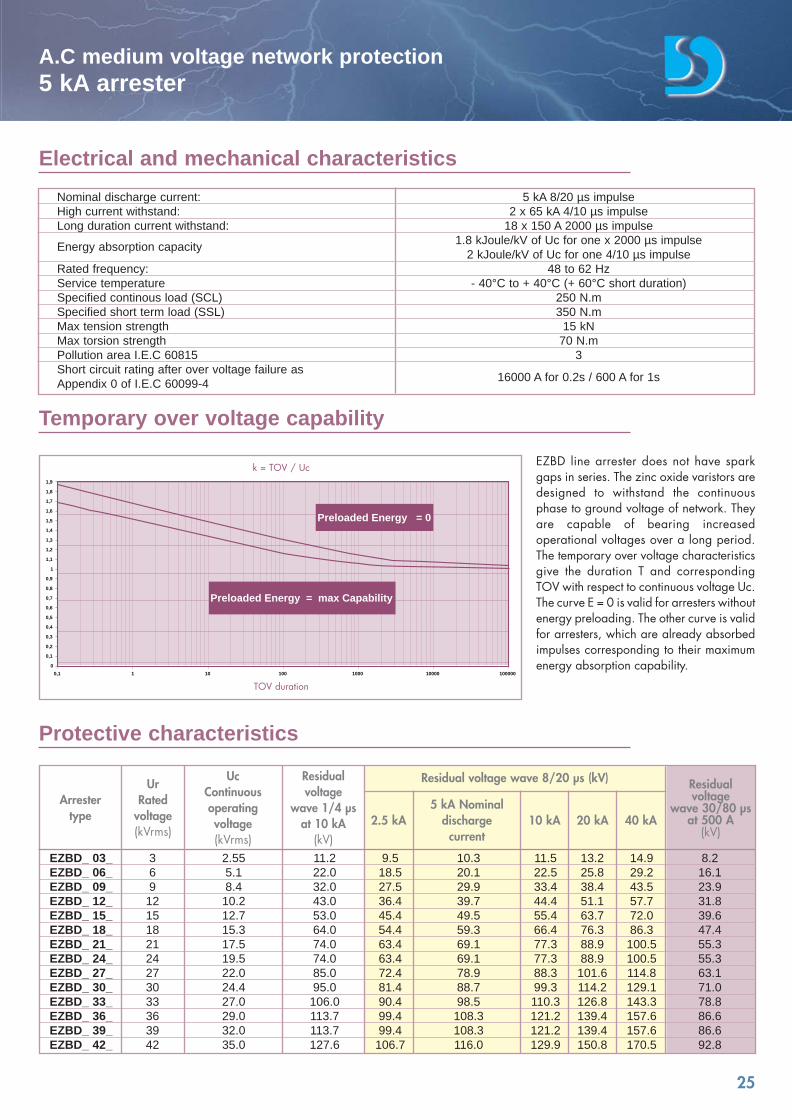
EZBD line arrester does not have sparkgaps in series. The zinc oxide varistors aredesigned to withstand the continuousphase to ground voltage of network. Theyare capable of bearing increasedoperational voltages over a long period.The temporary over voltage characteristicsgive the duration T and correspondingTOV with respect to continuous voltage Uc. The curve E = 0 is valid for arresters withoutenergy preloading. The other curve is validfor arresters, which are already absorbedimpulses corresponding to their maximumenergy absorption capability.
EZBD_ 03_ 3 2.55 11.2 9.5 10.3 11.5 13.2 14.9 8.2EZBD_ 06_ 6 5.1 22.0 18.5 20.1 22.5 25.8 29.2 16.1EZBD_ 09_ 9 8.4 32.0 27.5 29.9 33.4 38.4 43.5 23.9EZBD_ 12_ 12 10.2 43.0 36.4 39.7 44.4 51.1 57.7 31.8EZBD_ 15_ 15 12.7 53.0 45.4 49.5 55.4 63.7 72.0 39.6EZBD_ 18_ 18 15.3 64.0 54.4 59.3 66.4 76.3 86.3 47.4EZBD_ 21_ 21 17.5 74.0 63.4 69.1 77.3 88.9 100.5 55.3EZBD_ 24_ 24 19.5 74.0 63.4 69.1 77.3 88.9 100.5 55.3EZBD_ 27_ 27 22.0 85.0 72.4 78.9 88.3 101.6 114.8 63.1EZBD_ 30_ 30 24.4 95.0 81.4 88.7 99.3 114.2 129.1 71.0EZBD_ 33_ 33 27.0 106.0 90.4 98.5 110.3 126.8 143.3 78.8EZBD_ 36_ 36 29.0 113.7 99.4 108.3 121.2 139.4 157.6 86.6EZBD_ 39_ 39 32.0 113.7 99.4 108.3 121.2 139.4 157.6 86.6EZBD_ 42_ 42 35.0 127.6 106.7 116.0 129.9 150.8 170.5 92.8
Electrical and mechanical characteristics
Temporary over voltage capability
Protective characteristics
Arrestertype
UrRated
voltage(kVrms)
UcContinuousoperatingvoltage(kVrms)
Residualvoltage
wave 1/4 µsat 10 kA
(kV)2.5 kA 10 kA
5 kA Nominaldischarge
current20 kA 40 kA
Residualvoltage
wave 30/80 µsat 500 A
(kV)
Residual voltage wave 8/20 µs (kV)
Nominal discharge current: 5 kA 8/20 µs impulseHigh current withstand: 2 x 65 kA 4/10 µs impulseLong duration current withstand: 18 x 150 A 2000 µs impulse
Energy absorption capacity 1.8 kJoule/kV of Uc for one x 2000 µs impulse 2 kJoule/kV of Uc for one 4/10 µs impulse
Rated frequency: 48 to 62 HzService temperature - 40°C to + 40°C (+ 60°C short duration)Specified continous load (SCL) 250 N.mSpecified short term load (SSL) 350 N.mMax tension strength 15 kNMax torsion strength 70 N.mPollution area I.E.C 60815 3Short circuit rating after over voltage failure as Appendix 0 of I.E.C 60099-4 16000 A for 0.2s / 600 A for 1s
0
0,1
0,2
0,3
0,4
0,5
0,6
0,7
0,8
0,9
1
1,1
1,2
1,3
1,4
1,5
1,6
1,7
1,8
1,9
0,1 1 10 100 1000 10000 100000
Preloaded Energy = max Capability
Preloaded Energy = 0
k = TOV / Uc
TOV duration
catalogue Dervasil 30/05/08 16:36 Page 25
26
A.C medium voltage network protection5 kA arrester
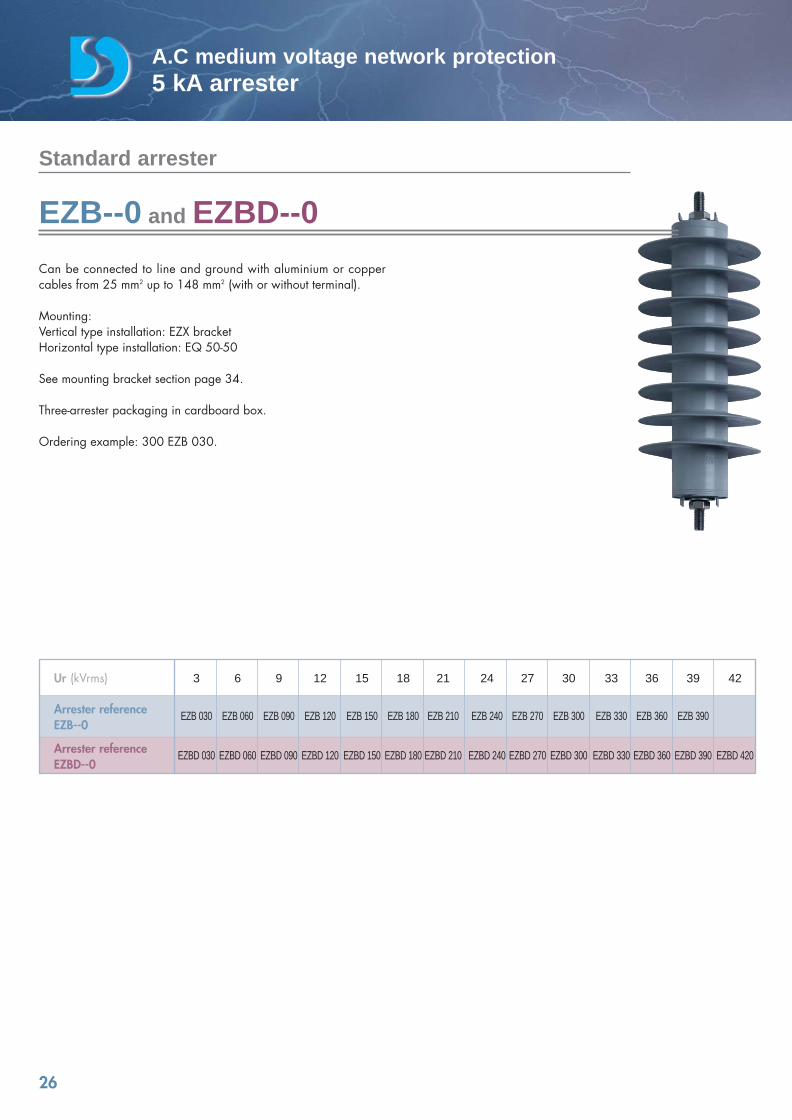
Can be connected to line and ground with aluminium or coppercables from 25 mm2 up to 148 mm2 (with or without terminal).
Mounting:Vertical type installation: EZX bracketHorizontal type installation: EQ 50-50
See mounting bracket section page 34.
Three-arrester packaging in cardboard box.
Ordering example: 300 EZB 030.
EZB--0 and EZBD--0
Ur (kVrms) 3 6 9 12 15 18 21 24 27 30 33 36 39 42
Arrester reference EZB 030 EZB 060 EZB 090 EZB 120 EZB 150 EZB 180 EZB 210 EZB 240 EZB 270 EZB 300 EZB 330 EZB 360 EZB 390EZB--0
Arrester reference EZBD 030 EZBD 060 EZBD 090 EZBD 120 EZBD 150 EZBD 180 EZBD 210 EZBD 240 EZBD 270 EZBD 300 EZBD 330 EZBD 360 EZBD 390 EZBD 420EZBD--0
Standard arrester
catalogue Dervasil 30/05/08 16:36 Page 26
27
A.C medium voltage network protection5 kA arrester
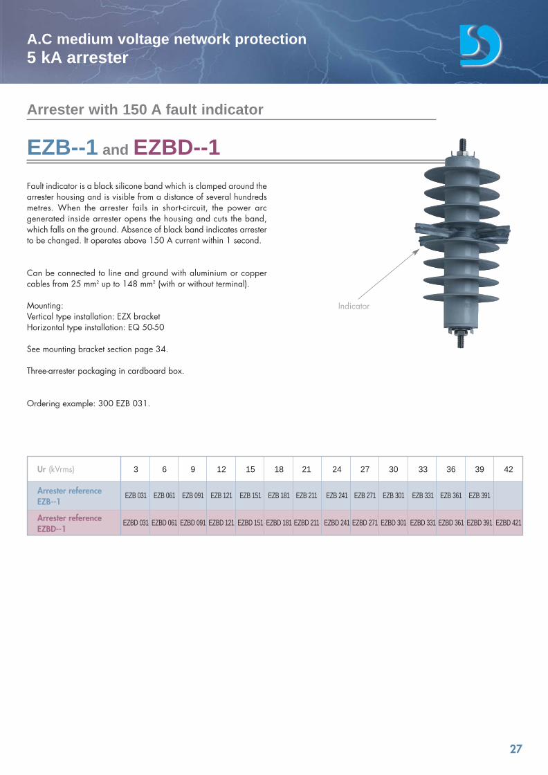
Fault indicator is a black silicone band which is clamped around thearrester housing and is visible from a distance of several hundredsmetres. When the arrester fails in short-circuit, the power arcgenerated inside arrester opens the housing and cuts the band,which falls on the ground. Absence of black band indicates arresterto be changed. It operates above 150 A current within 1 second.
Can be connected to line and ground with aluminium or coppercables from 25 mm2 up to 148 mm2 (with or without terminal).
Mounting:Vertical type installation: EZX bracketHorizontal type installation: EQ 50-50
See mounting bracket section page 34.
Three-arrester packaging in cardboard box.
Ordering example: 300 EZB 031.
Indicator
EZB--1 and EZBD--1
Ur (kVrms) 3 6 9 12 15 18 21 24 27 30 33 36 39 42
Arrester reference EZB 031 EZB 061 EZB 091 EZB 121 EZB 151 EZB 181 EZB 211 EZB 241 EZB 271 EZB 301 EZB 331 EZB 361 EZB 391EZB--1
Arrester reference EZBD 031 EZBD 061 EZBD 091 EZBD 121 EZBD 151 EZBD 181 EZBD 211 EZBD 241 EZBD 271 EZBD 301 EZBD 331 EZBD 361 EZBD 391 EZBD 421EZBD--1
Arrester with 150 A fault indicator
catalogue Dervasil 30/05/08 16:36 Page 27
150M10
20
28
A.C medium voltage network protection5 kA arrester
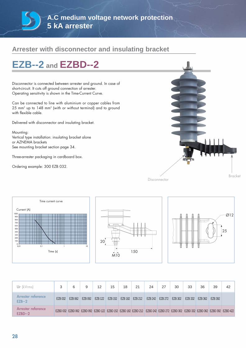
Disconnector is connected between arrester and ground. In case ofshort-circuit. It cuts off ground connection of arrester.Operating sensitivity is shown in the Time-Current Curve.
Can be connected to line with aluminium or copper cables from 25 mm2 up to 148 mm2 (with or without terminal) and to groundwith flexible cable.
Delivered with disconnector and insulating bracket.
Mounting:Vertical type installation: insulating bracket alone or AZNEMA bracketsSee mounting bracket section page 34.
Three-arrester packaging in cardboard box.
Ordering example: 300 EZB 032.
25
Ø12
Time current curve
Time (s)
Current (A)
Arrester with disconnector and insulating bracket
EZB--2 and EZBD--2
DisconnectorBracket
Ur (kVrms) 3 6 9 12 15 18 21 24 27 30 33 36 39 42
Arrester reference EZB 032 EZB 062 EZB 092 EZB 122 EZB 152 EZB 182 EZB 212 EZB 242 EZB 272 EZB 302 EZB 332 EZB 362 EZB 392EZB--2
Arrester reference EZBD 032 EZBD 062 EZBD 092 EZBD 122 EZBD 152 EZBD 182 EZBD 212 EZBD 242 EZBD 272 EZBD 302 EZBD 332 EZBD 362 EZBD 392 EZBD 422EZBD--2
catalogue Dervasil 30/05/08 16:36 Page 28