Embed Size (px)
Citation preview

133
Technical guides
Technical guidesContact arrangement / Assembly / Wiring / Example of cable clamp assembly / Attachment of panel connectors to a wall / Polarisation
Conn
ector
s with
non-r
emov
able
conta
ctsCo
nnect
ors w
ith re
mova
ble co
ntacts
Acces
sorie
s Tec
hnica
l guid
es

134
1
3
2
3
2 1 3
1
4 2
1
342
3
1
2
56
46
43
5
2
1
1
2
3
4
3
24
1 8
4
7
1 6
3
2
5
2
45
6
8
1
3
7
8
7 12
2
9
1
4
310
56 11 11
24
310 9
712
65
81
17 16
12
15
7
3
14
4
8
13
2 1
1716
3
13
8
14
1
4
2
15
12
7
101618
22 20
25 24
21
23
19
9
15
34 2
5
1
10
2120 2219
2523 24
16
5
1 2 3
1518
9
4
34
26
31
35
34
15
22
9
23
33 32
27
12
1016
5
27
32 33 34 35
31
23
16
10
5
1 2
2622
15
3 4
9
49
52
36
30
43
1523
37
50
44
31
24
916
82 1
3
44
50
9
3731
24
16
3 1
52
49
23
3643
30
15
28
Housing 13 contacts1 x ø 2 mm, 2 x ø 3 mm
Male panel connector Female panel connector contact ø 2 mm contact ø 3 mm contact ø 4 mmMale cable connector Female cable connector
Housing 1 4 contacts4 x ø 2 mm
Housing 1 6 contacts6 x ø 2 mm
Housing 24 contacts4 x ø 4 mm
Housing 28 contacts6 x ø 2 mm, 2 x ø 3 mm,
Housing 212 contacts12 x ø 2 mm
Housing 317 contacts15 x ø 2 mm, 2 x ø 3 mm,
Housing 425 contacts23 x ø 3 mm, 2 x ø 3 mm
Housing 535 contacts33 x ø 2 mm, 2 x ø 3 mm
Housing 552 contacts52 x ø 2 mm
Standard, Rapid, Waterproof and Hermetic Series
Identification of the contacts on the solder side
Contact arrangement
Dimensions and specifications may be changed without prior notice

135
3
25
4
16
4
51
3
2
6
3
8
4
2
5
6
7
1
5
6
1
78
3
4
2
10
4
8
11 12
1 3
7
12
10
11
7
3 1
8
4
131917
16
8
1 3
4 712
16
19
12
7
3 1
17
13
4
8
19
24
13
8
4
1
7
23
27
18
12
3 13
4
813
19
2427
23
18
12
7
Housing 007 contacts7 x ø 0,76 mm
Male panel connector Female panel connector contact ø 0,76 mmMale cable connector Female cable connector
Housing 0 8 contacts8 x ø 0,76 mm
Housing 0 12 contacts12 x ø 0,76 mm
Housing 0 19 contacts19 x ø 0,76 mm
Housing 127 contacts27 x ø 0,76 mm
Atto Miniature Push-Pull Serie
Identification of the contacts on the solder, crimp side
Contact arrangement
Dimensions and specifications may be changed without prior notice
Conn
ector
s with
non-r
emov
able
conta
ctsCo
nnect
ors w
ith re
mova
ble co
ntacts
Acces
sorie
s Tec
hnica
l guid
es

136
2
1 3
2
3 1
3
2 1
4 3
42
12 5
3 4
1 6
4
6
5
3
2
1
128
1110
4
1 3
7
12 11
7
10
3
8
1
4
1317
48
1
1916
12
37
131619 17
127
34
1
8
7
12
1823
34
1
272419
13
8 12
1823
27 24
37
1
19
13
8
4
1522
28
49
15
10
33
34 37
16
2329 33
28
22
3437
29
159
45
1
23
1610
16
24
9
31
31
3946
52
53 55
1710
4
2532
40
47 52
46
3931
916
24
5355
47
4032
25
3 1
4
17
10
Housing 003 contacts3 x ø 1 mmNatto Miniature Push-Pull, Minex Series
Male panel connector Female panel connector contact ø 1 mmMale cable connector Female cable connector
Housing 004 contacts4 x ø 1 mmNatto Miniature Push-Pull, Minex Series
Housing 07 contacts7 x ø 1 mmNatto Miniature Push-Pull, Minex Series
Housing 112 contacts12 x ø 1 mmNatto Miniature Push-Pull, Miniature, Marine, Neptunox,Robotic Series
Housing 119 contacts19 x ø 1 mmNatto Miniature Push-Pull, Miniature, Marine, Neptunox,Robotic Series
Housing 227 contacts27 x ø 1 mmMiniature, Marine, Neptunox, Robotic Series
Housing 237 contacts37 x ø 1 mmMiniature, Marine, Neptunox, Robotic Series
Housing 355 contacts55 x ø 1 mmMiniature Series
Miniature, Natto Miniature Push-Pull, Marine, Neptunox, Robotic and Minex Series
Identification of the contacts on the solder, crimp side
Contact arrangement
Dimensions and specifications may be changed without prior notice

137
1 3
2
13
2
1
42
3
2
3
4
1 6
5
43
2
1 1
2
34
5
6
4 7
31
12
10
11
8 10
12
8
11
3 1
47
17 19
7
12
1613
8
4
1 3 13
7
12
16 13
8
4
1719
9
4
20
24
27
15
1
10
5
21
16
25 27
20
24
9
15
4
10
25
21
16
1
5
31
2 2
3 1
42
3
1 1
3
4 2
6
5
1
3 4
2 5
34
6
2
1
3
7
10
1211
8
4
1 3
7
10
12 11
8
4
1
Housing 3 12 contacts12 x ø 2,4 mmIndustrial Series
Housing 13 contacts3 x ø 1,6 mmNatto Miniature Push-Pull, Industrial, Marine, Neptunox Series
Male panel connector Female panel connector contact ø 1,6 mm contact ø 2,4 mmMale cable connector Female cable connector
Housing 14 contacts4 x ø 1,6 mmNatto Miniature Push-Pull, Industrial, Marine, Neptunox Series
Housing 17 contacts7 x ø 1,6 mmNatto Miniature Push-Pull, Industrial, Marine, Robotic Series
Housing 2 12 contacts12 x ø 1,6 mm Industrial, Marine, Neptunox Series
Housing 3 19 contacts19 x ø 1,6 mmIndustrial Series
Housing 3 27 contacts27 x ø 1,6 mmIndustrial Series
Housing 1 3 contacts3 x ø 2,4 mmNatto Miniature Push-Pull, Industrial, Marine, Neptunox Series
Housing 1 4 contacts4 x ø 2,4 mmNatto Miniature Push-Pull, Industrial, Marine, Neptunox,Robotic Series
Housing 2 7 contacts7 x ø 2,4 mmIndustrial, Marine, Neptunox Series
Natto Miniature Push-Pull, Industrial, Marine, Neptunox and Robotic Series ø 1,6 mm and ø 2,4 mm
Identification of the contacts on the solder, crimp side
Contact arrangement
Dimensions and specifications may be changed without prior notice
Conn
ector
s with
non-r
emov
able
conta
ctsCo
nnect
ors w
ith re
mova
ble co
ntacts
Acces
sorie
s Tec
hnica
l guid
es

138
L1
1
L2
2
L2
2 1
L1 L1 L2 L2 L1
1
2
3
1
23
Housing 5Single-pole connector1 x ø 8 mm or 1 x ø 12 mm
Male panel connector Female panel connector contact ø 1,6 mm contact ø 8 mm contact ø 12 mmMale cable connector Female cable connector
Housing 5Multi-pole connector3 contacts x ø 8 mm + 2 pilot contacts ø 1,6 mm
Housing 5Multi-pole connector3 contacts ø 8 mm „Economic”
Housing 5Multi-pole connector4 contacts x ø 8 mm
Power Series Puissance
Identification of the contacts on the solder side
Contact arrangement
Dimensions and specifications may be changed without prior notice

139
3
5
2
41 71
9 31
1
8
3 2
8
17 14
13
1
9
5
Housing 17 contacts 13 contacts x ø 1 mm + 4 contacts ø 2,4 mm
Male panel connector Female panel connector contact ø 1 mm contact ø 2,4 mmMale cable connector Female cable connector
Identification of the contacts on the solder side
Dimensions and specifications may be changed without prior notice
Contact arrangement
Conn
ector
s with
non-r
emov
able
conta
ctsCo
nnect
ors w
ith re
mova
ble co
ntacts
Acces
sorie
s Tec
hnica
l guid
es
Industrial and Robotics Series with 17 mixed contacts

140
1
34
2
5
61
54
6
3
2
17
6
5
3
4
28
12
3
4
6
5
78
3174
108
1211
1347
810
1112
19
3
12
16
7
17
1
8
13
4
17
1
8
13
4
19
3
12
16
7
2
1 3
2
3 11
2 3
4 14
3 2
16
2
5
34
61
5
2
43
10
3
4
8
7
1
1211
8
1
7
10
4
3
1112
314 7
17
8
19
12
1613
137 4
19
12
17
8
1316
31
4 7
23
8
27
12
1813
19
24
13
7 4
19
12
14
8
1318
23
27
415 9
28
10
33
15
2216
23
293734
14
9 5
23
15
29
10
1622
28
333437
Housing 007 x ø 0,76 mm
Male panel connector Female panel connector contact ø 0,76 mm contact ø 1 mmMale cable connector Female cable connector
Housing 08 x ø 0,76 mm
Housing 012 x ø 0,76 mm
Housing 019 x ø 0,76 mm
Housing 003 x ø 1 mm
Housing 004 x ø 1 mm
Housing 07 x ø 1 mm
Housing 112 x ø 1 mm
Housing 119 x ø 1 mm
Housing 227 x ø 1 mm
Housing 237 x ø 1 mm
Neptunox Series
Identification of the contacts on the solder, crimp side
Contact arrangement
Dimensions and specifications may be changed without prior notice

141
1 3
2
3 1
2
1
4
3
2
1
4
3
2
61
2
5
34
61
2
5
3
4
31
4 7
8 10
1112
13
7 4
10 8
1211
1 3
2
3 1
2
1
4
3
2
1
4
3
2
61
2
5
4
3
16
5
2
3
4
Male panel connector Female panel connector contact ø 1,6 mm contact ø 2,4 mmMale cable connector Female cable connector
Housing 13 x ø 1,6 mm
Housing 14 x ø 1,6 mm
Housing 17 x ø 1,6 mm
Housing 212 x ø 1,6 mm
Housing 13 x ø 2,4 mm
Housing 14 x ø 2,4 mm
Housing 27 x ø 2,4 mm
Neptunox Series
Identification of the contacts on the solder, crimp side
Contact arrangement
Dimensions and specifications may be changed without prior notice
Conn
ector
s with
non-r
emov
able
conta
ctsCo
nnect
ors w
ith re
mova
ble co
ntacts
Acces
sorie
s Tec
hnica
l guid
es
142
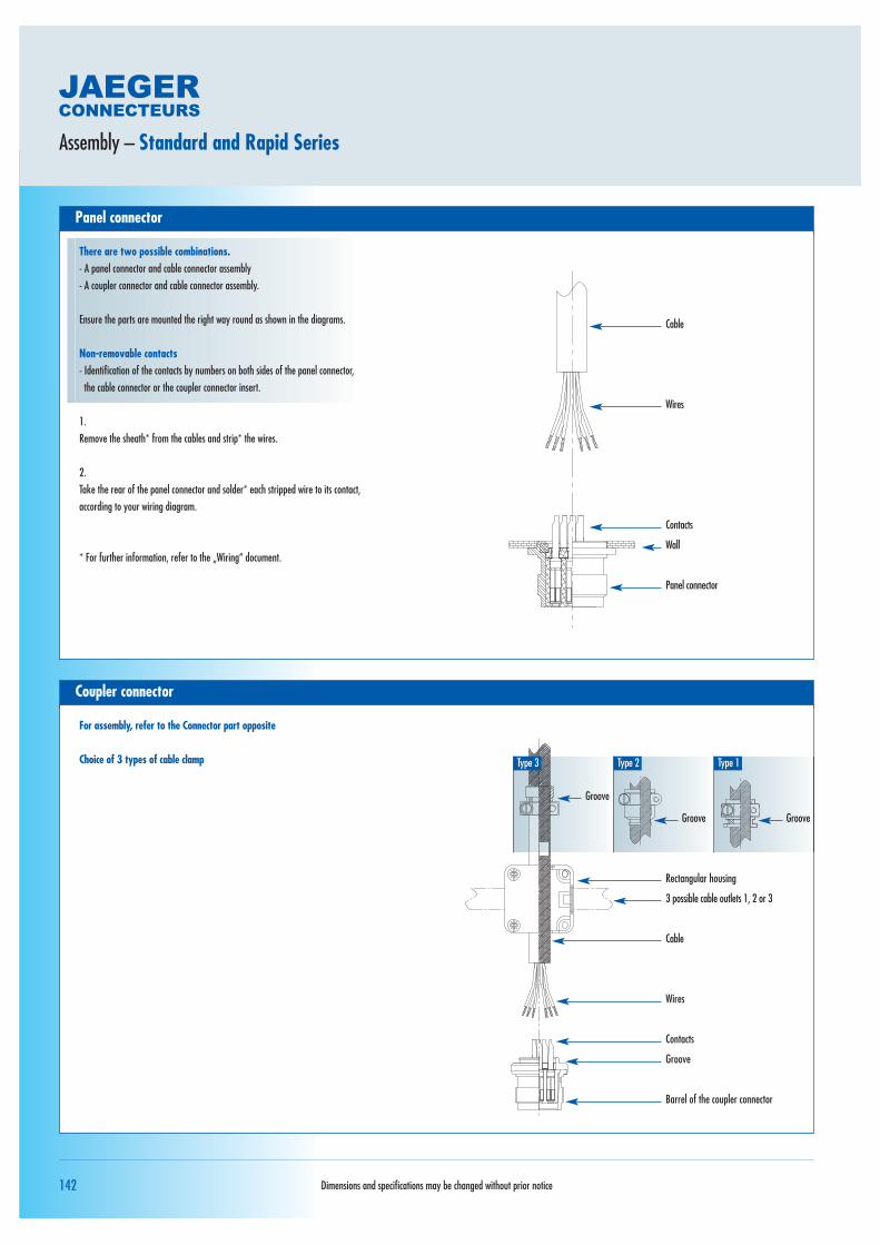
Panel connector
Assembly – Standard and Rapid Series
Coupler connector
Cable
Wires
Contacts
Panel connector
Wall
For assembly, refer to the Connector part opposite
Choice of 3 types of cable clamp
Rectangular housing
3 possible cable outlets 1, 2 or 3
Cable
Type 2Type 3 Type 1
Groove
Groove Groove
Contacts
Barrel of the coupler connector
Groove
Wires
Dimensions and specifications may be changed without prior notice
There are two possible combinations.- A panel connector and cable connector assembly- A coupler connector and cable connector assembly.
Ensure the parts are mounted the right way round as shown in the diagrams.
Non-removable contacts- Identification of the contacts by numbers on both sides of the panel connector,
the cable connector or the coupler connector insert.
1.Remove the sheath* from the cables and strip* the wires.
2. Take the rear of the panel connector and solder* each stripped wire to its contact, according to your wiring diagram.
* For further information, refer to the „Wiring“ document.

143
Cable connector
Choice of 3 types of cable clamp
1.Unscrew the 4 screws and open the two half-shells of the housing.Separate the parts.
(2 half-shells and a cable connector barrel).
2.Slide the cable into the cable clamp.
3.Remove the sheath* from the cables and strip* the wires.
4.Take the rear of the cable connector barrel and solder* each stripped wire to its contact, according to your wiring diagram.
5.Take a half-shell and place the groove of the cable connector barreland the groove of the cable clamp into it in their respective seatingsas shown in diagram 1 tighten the 2 screws on the cable clamp.
6.Then close the assembly with the other half-shell, using the 4 screws.
* For further information, refer to the „Wiring“ document.
Assembly – Standard and Rapid Series
Rectangular housing
3 possible cable outlets 1, 2 or 3
Cable
Type 2Type 3
Diagram 2
Type 1
GrooveGroove Groove
Contacts
Cable connector barrel
Groove
Wires
Position of the groove of the cable clamp in the shell
Position of the groove of the barrelof the cable connector in the shell
Dimensions and specifications may be changed without prior notice
Conn
ector
s with
non-r
emov
able
conta
ctsCo
nnect
ors w
ith re
mova
ble co
ntacts
Acces
sorie
s Tec
hnica
l guid
es

144
Coupler connector
Assembly – Waterproof, Waterproof High-Performance and PG outlet Series
Panel connector
There are two possible combinations.- A panel connector and cable connector assembly- A coupler connector and cable connector assembly.
Ensure the parts are mounted the right way round as shown in the diagrams.
Non-removable contacts- Identification of the contacts by numbers on both sides of the panel connector,
the cable connector or the coupler connector insert. For further information, refer to the „Contact arrangement“ document.
1.Remove the sheath* from the cables and strip* the wires.
2. Take the rear of the panel connector and solder* each stripped wireto its contact, according to your wiring diagram.
* For further information, refer to the „Wiring“ document.
For assembly, refer to the connector part (Standard Waterproof) opposite
Cable
Wires
Square panel connectorRound panel connector
Contacts
Wall
Contacts
Wall
Cable
Waterproof boot
Circular housing with small or largeoutlet integral cable clamp
Wires
Contacts
Barrel of the coupler connector
Dimensions and specifications may be changed without prior notice

145
Assembly – Waterproof, Waterproof High-Performance and PG outlet Series
Cable connector
Standard Waterproof
1.Unscrew all the parts of the cable connector.
2.Slide the cable into the circular housing with its integral cable clamp,followed by the waterproof boot.
3.Remove the sheath* from the cables and strip* the wires.
4.Take the rear of the cable connector barrel and solder* each stripped wire to its contact, according to your wiring diagram.
5.Next fit the waterproof boot inside the circular housing. Then screw the assembly onto the barrel of the cable connector.
6.Tighten the 2 screws on the cable clamp.
* For further information, refer to the „Wiring“ document.
Waterproof High-Performance Cable Gland and PG outlet
1.Unscrew all the parts of the cable connector.
2.Slide the cable into the circular housing with its integral cable clamp, followed by the waterproof boot.
3., 4., 5. and 6. refer to instructions 3., 4., 5. and 6. above.
Waterproof boot
Cable
Circular housing with small or large outlet integral cable clamp
Contacts
Cable connector barrel
Wires
Circular housing
Cable
Cable clamp
Wires
Contacts
Cable connector barrel
Waterproof boot
Dimensions and specifications may be changed without prior notice
Conn
ector
s with
non-r
emov
able
conta
ctsCo
nnect
ors w
ith re
mova
ble co
ntacts
Acces
sorie
s Tec
hnica
l guid
es

146
Coupler connector
Assembly – Miniature Push-Pull Series
Panel connector
There are two possible combinations.- A panel connector and cable connector assembly- A coupler connector and cable connector assembly.
Ensure the parts are mounted the right way round as shown in the diagrams.
Removable contactsAll the contacts must be mounted in the insert.- Dentification of the contacts by numbers on both sides of the panel connector, the cable connector or the coupler connector insert. For further information, refer to the „Contact arrangement“ document.
1.Remove the sheath* from the cables and strip* the wires.
2.Solder* or crimp each stripped wire onto its contact.
3. Then take the rear of the panel connector and insert* the wired contacts into the insert using the insertion tool*, according to your wiring diagram.
* For further information, refer to the „Wiring“ document
For assembly, refer to the Connector part opposite
Cable
Wires
Contacts
Panel connector
Wall
Cable
Cable gland (accessory)
Contacts
Barrel of the coupler connector
Wires
Dimensions and specifications may be changed without prior notice

147
Assembly – Miniature Push-Pull Series
Cable connector
Connection accessories Choice of 3 couplings:
Cable gland
1.Unscrew all the parts of the cable connector.
2.Slide the cable into the cable gland coupling, followed by the claw, the cable gland seal and the seal holder.
Cable
Coupling
Washer
Seal
Seal holder
Cable
Cable gland coupling
Claw
Cable gland seal
Cone
Pusher
Claw
Cable gland seal
Seal holder
Cable
Cable gland coupling
Cable connector barrel
Contacts
Wires
Cable gland
Cable clamp Cable glandwith 360°shieldconnection
Dimensions and specifications may be changed without prior notice
Conn
ector
s with
non-r
emov
able
conta
ctsCo
nnect
ors w
ith re
mova
ble co
ntacts
Acces
sorie
s Tec
hnica
l guid
es
Cable clamp
1.Unscrew all the parts of the cable connector.
2. Slide the cable into the coupling, followed by the washer, the seal and the seal holder.
3.3., 4., 5. and 6. refer to instructions 3., 4., 5. and 6. above.
7.Tighten the screws on the cable clamp.
Cable gland with 360° shield connection
1.Unscrew all the parts of the cable connector.
2.Slide the cable into the circular housing with its integral cable clamp, followed by the waterproof boot.
3., 4., 5. and 6. refer to instructions 3., 4., 5. and 6. above.
3.Remove the sheath* from the cables and strip* the wires.
4.Solder* or crimp each stripped wire onto its contact.
5. Then take the rear of the cable connector barrel and insert* the wired contacts into the insert using the insertion tool*, according to your wiring diagram.
6.Next join all the parts of the connection accessory together. Then screw the assembly onto the barrel of the cable connector.
* For further information, refer to the „Wiring“ document.

148
Coupler connector
Assembly – Miniature and Industrial Series
Panel connector
There are two possible combinations.- A panel connector and cable connector assembly- A coupler connector and cable connector assembly.
Ensure the parts are mounted the right way round as shown in the diagrams.
Removable contactsAll the contacts must be mounted in the insert.- Dentification of the contacts by numbers on both sides of the panel connector, the cable connector or the coupler connector insert. For further information, refer to the „Contact arrangement“ document.
1.Remove the sheath* from the cables and strip* the wires.
2.Solder* or crimp each stripped wire onto its contact.
3. Then take the rear of the panel connector and insert* the wired contacts into the insert using the insertion tool*, according to your wiring diagram.
* For further information, refer to the „Wiring“ document.
For assembly, refer to the Connector part opposite
Choice of 3 types of cable clamp (accessory)(for further information, refer to the „Cable clamp“ document)
Cable
Wires
Contacts
Panel connector
Wall
Rectangular housing
3 possible cable outlets 1, 2 or 3
Groove
Barrel of the coupler connector
Contacts
Wires
Type 1Type 3 Type 2
Groove Groove Groove
Dimensions and specifications may be changed without prior notice

149
Assembly – Miniature and Industrial Series
Cable connector
Rectangular housing
3 possible cable outlets 1, 2 or 3
Cable
Type 1Type 3
Diagram 1
Type 2
GrooveGroove Groove
Contacts
Cable connector barrel
Groove
Wires
Place the groove of the cable clamp into the shell
Place the groove of the cable connectorbarrel into the shell.
Dimensions and specifications may be changed without prior notice
Conn
ector
s with
non-r
emov
able
conta
ctsCo
nnect
ors w
ith re
mova
ble co
ntacts
Acces
sorie
s Tec
hnica
l guid
es
Choice of 3 types of cable clamp (accessory)(for further information, refer to the „Cable clamp“ document)
Cable gland
1.Unscrew the screws and open the two half-shells of the housing. Separate the parts.
(2 half-shells and a cable connector barrel).
2.Slide the cable into the cable clamp.
3.Remove the sheath* from the cables and strip* the wires.
4.Solder* or crimp each stripped wire onto its contact.
5. Then take the rear of the cable connector barrel and insert* the wired contacts into the insert using the insertion tool*, according to your wiring diagram.
6.Take a half-shell and place the groove of the cable clamp and the groove of the able connector barrel into it, in their respective seatings according to diagram 1. Tighten the screws on the cable clamp.
7. Then close the assembly with the other half-shell, using the 4 screws.
* For further information, refer to the „Wiring“ document.

150
Coupler connector
Assembly – Waterproof Miniature and Industrial Waterproof Series
Panel connector
There are two possible combinations.- A panel connector and cable connector assembly- A coupler connector and cable connector assembly.
Ensure the parts are mounted the right way round as shown in the diagrams.
Removable contactsAll the contacts must be mounted in the insert.- Identification of the contacts by numbers on both sides of the panel connector, the cable connector or the coupler connector insert. For further information, refer to the „Contact arrangement“ document.
1.Remove the sheath* from the cables and strip* the wires.
2.Solder* or crimp each stripped wire onto its contact.
3. Then take the rear of the panel connector and insert* the wired contacts intothe insert using the insertion tool*, according to your wiring diagram.
* For further information, refer to the „Wiring“ document.
For assembly, refer to the Connector part oppositeCable
PG cable clamp (accessory)
Circular housing
Waterproof boot
Contacts
Barrel of the coupler connector
Wires
Cable
Wires
Contacts
Panel connector
Wall
Dimensions and specifications may be changed without prior notice

151
Assembly – Waterproof Miniature and Industrial Waterproof Series
Cable connector
1.Unscrew all the parts of the cable connector.
2.Slide the cable into the cable clamp, followed by the circular housingand the waterproof boot.
3.Remove the sheath* from the cables and strip* the wires.
4.Solder* or crimp each stripped wire onto its contact.
5. Then take the rear of the cable connector barrel and insert* thewired contacts into the insert using the insertion tool*, according toyour wiring diagram.
6.Next fit the waterproof boot inside the circular housing. Then screw the assembly onto the barrel of the cable connector.
7. Tighten the screws on the cable clamp.
* For further information, refer to the „Wiring“ document.
Circular housing
Waterproof boot
Cable
PG cable clamp (accessory)
Cable connector barrel
Contacts
Wires
Dimensions and specifications may be changed without prior notice
Conn
ector
s with
non-r
emov
able
conta
ctsCo
nnect
ors w
ith re
mova
ble co
ntacts
Acces
sorie
s Tec
hnica
l guid
es

152
Coupler connector
Assembly – Marine Series
Panel connector
There are two possible combinations.- A panel connector and cable connector assembly- A coupler connector and cable connector assembly.
Ensure the parts are mounted the right way round as shown in the diagrams.
Removable contactsAll the contacts must be mounted in the insert.- Identification of the contacts by numbers on both sides of the panel connector,
the cable connector or the coupler connector insert. For further information, refer to the „Contact arrangement“ document.
1.Remove the sheath* from the cables and strip* the wires.
2.Solder* or crimp each stripped wire onto its contact.
3. Then take the rear of the panel connector and insert* the wired contacts into the insert using the insertion tool*, according to your wiring diagram.
* For further information, refer to the „Wiring“ document.
For assembly, refer to the Connector part opposite
Cable
Wires
Contacts
Cable
Cone
Seal
Circular housing with cable clamp
Seal holder
Contacts
Barrel of the coupler connector
Wires
Wall Wall
Square panel connectorCircular panel connector
Dimensions and specifications may be changed without prior notice

153
Assembly – Marine Series
Cable connector
1.Unscrew all the parts of the cable connector.
2.Slide the cable into the cable clamp, followed by the cone, the seal and the seal holder
3.Remove the sheath* from the cables and strip* the wires.
4.Solder* or crimp each stripped wire onto its contact.
5. Then take the rear of the cable connector barrel and insert* the wired contacts into the insert using the insertion tool*, according to your wiring diagram.
6.Next add the cone followed by the seal and the seal holder in the circular housing with the cable clamp incorporated. Then screw the assembly onto the barrel of the cable connector.
7. Tighten the screws on the cable clamp.
* For further information, refer to the „Wiring“ document.
Seal
Cone
Contacts
Wires
Seal holder
Cable
Circular housing with cable clamp
Cable connector barrel
Dimensions and specifications may be changed without prior notice
Conn
ector
s with
non-r
emov
able
conta
ctsCo
nnect
ors w
ith re
mova
ble co
ntacts
Acces
sorie
s Tec
hnica
l guid
es

154
1
Coupler connector
Assembly – Robotic Series
Panel connector
There are two possible combinations.- A panel connector and cable connector assembly- A coupler connector and cable connector assembly.
Ensure the parts are mounted the right way round as shown in the diagrams.
Removable contactsAll the contacts must be mounted in the insert.- Identification of the contacts by numbers on both sides of the panel connector,
the cable connector or the coupler connector insert. For further information,refer to the „Contact arrangement“ document.
1.Remove the sheath* from the cables and strip* the wires.
2.Solder* or crimp each stripped wire onto its contact.
3. Then take the rear of the panel connector and insert* the wired contacts into the insert using the insertion tool*, according to your wiring diagram.
* For further information, refer to the „Wiring“ document.
For assembly, refer to the Connector part opposite
Cable
Wires
Contacts
Panel connector
Wall
Cable
Cable clamp
Groove
3 possible cable outlets 1, 2 and 3
Rectangular housing
Contacts
Wires
Groove
Barrel of the coupler connector
Dimensions and specifications may be changed without prior notice
Rear view

155
Assembly – Robotic Series
Cable connector
1.Unscrew the screws and open the two half-shells of the housing.Separate the parts.
(2 half-shells and a cable connector barrel).
2.Slide the cable into the cable clamp.
3.Remove the sheath* from the cables and strip* the wires.
4.Solder* or crimp each stripped wire onto its contact.
5. Then take the rear of the cable connector barrel and insert* thewired contacts into the insert using the insertion tool*, according toyour wiring diagram.
6.Take a half-shell and place the groove of the cable clamp and thegroove of the cable connector barrel into it, in their respective seatingsaccording to diagram 1. Tighten the screws on the cable clamp.
7. Then close the assembly with the other half-shell, using the 4 screws.
* For further information, refer to the „Wiring“ document.
3 possible cable outlets 1, 2 or 3
Groove
Contacts
Groove
Wires
Rectangular housing
Cable
Cable clamp
Cable connector barrel
Diagram 1
Place the groove of the cable clamp into the shell
Place the groove of the cable connectorbarrel into the shell
Dimensions and specifications may be changed without prior notice
Conn
ector
s with
non-r
emov
able
conta
ctsCo
nnect
ors w
ith re
mova
ble co
ntacts
Acces
sorie
s Tec
hnica
l guid
es

156
1
Coupler connector
Assembly – Robotic with 17 mixed contacts
Panel connector
There are two possible combinations.- A panel connector and cable connector assembly- A coupler connector and cable connector assembly.
Ensure the parts are mounted the right way round as shown in the diagrams.
Removable contactsAll the contacts must be mounted in the insert.- Identification of the contacts by numbers on both sides of the panel connector, the
cable connector or the coupler connector insert. For further information, refer to the„Contact arrangement“ document.
1.Remove the sheath* from the cables and strip* the wires.
2.Solder* or crimp each stripped wire onto its contact.
3. Then take the rear of the panel connector and insert* the wired contacts into the insert using the insertion tool*, according to your wiring diagram.
* For further information, refer to the „Wiring“ document.
For assembly, refer to the Connector part opposite
Cable
Wires
Contacts
Panel connector
Wall
Rear view
Dimensions and specifications may be changed without prior notice

157
Assembly – Robotic with 17 mixed contacts
Cable connector
Diagram 1
1.Unscrew the screws and open the two half-shells of the housing. Then separate the parts.
(2 half-shells and a cable connector barrel).
2.Slide the cable into the cable clamp, the pressure washer, the thermo-adhesive sheath and the boot.
3.Solder* or crimp each stripped wire onto its contact. Then take the rear of the cable connector barrel and insert the wired contacts into the insert using the insertion tool, according to your wiring diagram.
* For further information, refer to the „Wiring“ document.
Diagram 2
4.Install the boot at the rear of the cable connector barrel. Place the toothed washer initially between the pressure washer and the boot (required for the ground connection).
Diagram 3
5.Fit the 4 screws starting by the one linked to the toothed washer (screw A). Fully tighten the 4 screws on the pressure washer.
Diagram 4
6.Place the thermo-adhesive sheath on the boot/cable. Stretch the thermo-adhesive sheathon the boot and the cable conduit, taking care to heat the thermo-adhesive sheath evenlyto ±100 °C in order to completely liquefy the adhesive.
Diagram 5
7.Take a half-shell and place the groove of the cable clamp and the groove of the cable connector barrel into it, in their respective seatings.Tighten the screws on the cable clamp. Then close the assembly with the other half-shell,using the 4 screws.
cable clamp
Shrunk thermo- adhesive sheath
Boot
Cable connector barrel
Cable clamp Cable clamp
Thermo-adhesive sheath
Thermo-adhesive sheath
Boot Boot
Pressure washerPressure washerToothed washer
Cable connector barrel
Cable connector barrel
cable clamp
3 possible cable outlets 1, 2 and 3
Rectangular shell
Cable connector barrel
Screw A
Toothed washer
Diagram 4
Diagram 2
Diagram 1
Diagram 5
1
23
Diagram 3
Groove
Pressure washer
Thermo-adhesive sheath
Contacts
Groove
Wires
Boot
Cable
Cable clamp
Cable connector barrel
Dimensions and specifications may be changed without prior notice
Conn
ector
s with
non-r
emov
able
conta
ctsCo
nnect
ors w
ith re
mova
ble co
ntacts
Acces
sorie
s Tec
hnica
l guid
es

158
Coupler connector
Assembly – Minex Series
Panel connector
There are two possible combinations.- A panel connector and cable connector assembly- A coupler connector and cable connector assembly.
Ensure the parts are mounted the right way round as shown in the diagrams.
Removable contactsAll the contacts must be mounted in the insert.- Identification of the contacts by numbers on both sides of the panel connector, the
cable connector or the coupler connector insert. For further information, refer to the„Contact arrangement“ document.
1.Remove the sheath* from the cables and strip* the wires.
2.Solder* or crimp each stripped wire onto its contact.
3. Then take the rear of the panel connector and insert* the wired contacts into the insert using the insertion tool*, according to your wiring diagram.
* For further information, refer to the „Wiring“ document.
For assembly, refer to the Connector part opposite
Cable
Wires
Contacts
Wall
Panel connector
Coupling
Cable
Claw
Seal
Barrel of the coupler connector
Wires
Contacts
Dimensions and specifications may be changed without prior notice

159
Assembly – Minex Series
Cable connector
1.Unscrew all the parts of the cable connector.
2.Slide the cable into the coupling, followed by the claw and the seal.
3.Remove the sheath* from the cables and strip* the wires.
4.Solder* or crimp each stripped wire onto its contact.
5.Then take the rear of the cable connector barrel and insert* the wired contacts into the insert using the insertion tool*, according to your wiring diagram.
6.Next add the claw followed by the seal in the coupling. Then screw the assembly with the barrel of the cable connector.
* For further information, refer to the „Wiring“ document.
Claw
Contacts
Cable connector barrel
Wires
Seal
Cable
Coupling
Dimensions and specifications may be changed without prior notice
Conn
ector
s with
non-r
emov
able
conta
ctsCo
nnect
ors w
ith re
mova
ble co
ntacts
Acces
sorie
s Tec
hnica
l guid
es

160
Coupler connector
Assembly – Power Series Puissance
Panel connector
There are two possible combinations.- A panel connector and cable connector assembly- A coupler connector and cable connector assembly.
Ensure the parts are mounted the right way round as shown in the diagrams.
Removable contactsAll the contacts must be mounted in the insert.- Identification of the contacts by numbers on both sides of the panel connector,
the cable connector or the coupler connector insert. For further information, refer to the „Contact arrangement“ document.
1.Remove the sheath* from the cable and slide each wire into its bushing. Strip* the wires.
2.Crimp* each stripped wire to its contact.
3. Then take the rear of the panel connector and insert the wired contacts into the insert, according to your wiring diagram. Then insert the bushings, screwing them up using the specific tool*.
* For further information, refer to the „Wiring“ document.
For assembly, refer to the Connector part oppositeCable
Panel connector
Dimensions and specifications may be changed without prior notice
Cable clamp
Flanges
Circular housing
Barrel of the coupler connector

161
Cable
Cable clamp
Flange
Straight coupling
Friction washer
Nut
Pilot contacts ø 1,6 mm
Socket holder
Cable connector barrel
Assembly – Power Series Puissance
Cable connector
1.Unscrew all the parts of the cable connector.
2.Slide the cable into the cable gland with the flanges loosened, followed by the straight coupling, the friction washer and the nut.
3.Remove the sheath* from the cable and slide each wire into itsbushing. Strip* the wires.
4.Crimp* each stripped wire to its contact.
5.Then take the rear of the cable connector barrel and insert* the wired contacts into theinsert, according to your wiring diagram. Then insert the bushings, screwing them up usingthe specific tool*. - Place the ground contact in its seating, taking care to position the hole of contact „X“
in line with the hole „S“ of the cable connector barrel. Attach the ground contact with the ground screw.
- For cable connectors with male contacts, only on the pilot contacts, first insert the socketholders, then the wired pilot contacts and finish with the bushings.
6.Add the nut and the friction washer and the straight coupling and screw the assembly to the cable connector barrel.
7.Screw the cable clamp onto the straight coupling. Tighten the screws on the cable clamp. Apply weak threadlock on the threaded part of the cable clamp.
* For further information, refer to the „Wiring“ document.
Contact bushing
Pilot contacts ø 12 mm or ø 8 mm
Ground screw
Circular housing
Dimensions and specifications may be changed without prior notice
Conn
ector
s with
non-r
emov
able
conta
ctsCo
nnect
ors w
ith re
mova
ble co
ntacts
Acces
sorie
s Tec
hnica
l guid
es

162
ø C
ø MQ ø O
P
ø O ø N
ø M
P
R
ø A ø B ø C1 3,2 28 21,22 3,2 34 27,23 4,2 48 39,24 4,2 54 45,25 4,2 62 52,2
1 21,1 34 M21 2,5 24,9 232 27,1 40 M27 2,5 30,9 293 39,1 56,2 M39 2 41,4 40,24 45,1 62,2 Tr45 1,6 47,4 46,25 52,1 69,2 Tr52 2,1 54,4 53,2
Circular panel connectors: attachment by locknuts Standard, Waterproof and Hermetic Series
4 holes ø A to 90° on ø B
Seal
Panel connector
Wall
Attachment of panel connectors to a wall
Square and circular panel connectors for the Standard, Rapid, Waterproof, Miniature, Industrial, Marine, Neptunox and Robotic Series
After drilling the holes in the wall (hole ø C and 4 holes ø A), place the gasket* followed by the panel connector against the wall. Screw up using the 4 screws and nuts**.The assembly is sealed by crushing the gasket between the wall and the panel connector.*Gaskets under panel connector (not supplied with the panel connector), see: Accessories.**Attachment of the square panel connector by 4 screws and nuts (not supplied with the panel connector), see: Accessories.Housings B1 and B2: 4 screws and M3 nutsHousings B3, B4 and B5: 4 screws and M4 nuts
After drilling the holes in the wall, fit the O-ring in the groove on the collar of the panel connector. Then fit the panel connector, the lock washer and finally the nut.The assembly is sealed by crushing the gasket between the wall and the panel connector.
Housing
Dimensions and specifications may be changed without prior notice
The cutting out of the supporting wall, as shown below, may be different depending on the thickness of the wall.Housing ø M ø N ø O P Q R
min.
Panel connectorWall
O-ringLock washer
Nut
Panel connectorWall
O-ringNut
Diagram 1: Thickness of the wall between 2 and 4 mm Diagram 2: Thickness of the wall greater than 4 mm
2 min.4 max.

163
B
C ø A
D
C ø A
3
12
C
1 2 3
2 1 3
1 2 3
1 3 2
4
4
1 2 3
5 4 3
4
2
5
1
6
6
1 2 3
2 1 5
4
4
5
3
6
6
7
8
8
7
1 2 3
5 4 3
4
2
5
1
6
6
7
12
8
11
9
10
10
9
11
8
12
7
1 2 3
3 2 1
4
7
5
6
6
5
7
4
8
12
9
11
10
10
11
9
12
8
13
15
14
14
15
13
16
17
17
16
36 37 38
31 43 42
39
41
40
40
41
39
42
38
43
37
44
49
45
48
46
47
47
46
48
45
49
44
50
52
51
51
52
50
1 2 3
4 3 2
4
1
5
9
6
8
7
7
8
6
9
5
10
15
11
14
12
13
13
12
14
11
15
10
16
18
17
17
18
16
19
22
20
21
21
20
22
19
23
25
24
24
25
23
1 2 3
4 3 2
4
1
5
9
6
8
7
7
8
6
9
5
10
15
11
14
12
13
13
12
14
11
15
10
16
22
17
21
18
20
19
19
20
18
21
17
22
16
23
26
24
25
25
24
26
23
27
31
28
30
29
29
30
28
31
27
32
35
33
34
34
33 32
35
1 2 3
4 3 2
4
1
5
9
6
8
7
7
8
6
9
5
10
15
11
14
12
13
13
12
14
11
15
10
16
22
17
21
18
20
19
19
20
18
21
17
22
16
23
26
24
25
25
24
26
23
27
31
28
30
29
29
30
28
31
27
32
35
33
34
34
33 32
35
B 1 B 2 B 3 B 4 B 5
A ø 21 ø 27 ø 39,5 ø 45,5 ø 52,5B 2,5 2,5 2,5 2,5 2,5C 12,5 15,5 20,7 23,7 27,2
Bulkhead connector for Hermetic Series
The cutting out of the supporting wall, as shown below, may be different depending on the thickness of the wall.Thicknessof the Diagram 1 Diagram 2 Diagram 1 Diagram 2 Diagram 2 Diagram 2 Diagram 2wall 2 to 3 3 to 10 2 to 3 3 to 10 2 to 10 2 to 10 2 to 10
After drilling the holes in the wall, fit the O-ring in the groove on the collar of the bulkhead connector. Then fit the bulkhead connector, the lock washer and finally the nut.The assembly is sealed by crushing the gasket between the wall and the bulkhead connector.
As the bulkhead connector is fitted with male contacts on both sides, the identification of the same conductor is different in the two female cable connectors mated to this connector.See the table of equivalences below.
Dimensions and specifications may be changed without prior notice
Diagram 1: Thickness of the wall between 2 and 10 mm
Housing 13-4-6 contacts
Housing 28-12 contacts
Housing 317 contacts
Housing 425 contacts
Housing 535 contacts
Housing 555 contacts
Diagram 2: Thickness of the wall greater than 10 mm Bulkhead connector2 min.10 max.
Attachment of panel connectors to a wall
Conn
ector
s with
non-r
emov
able
conta
ctsCo
nnect
ors w
ith re
mova
ble co
ntacts
Acces
sorie
s Tec
hnica
l guid
es
164
ø A
ø A
B
C
ø A
D
ø A
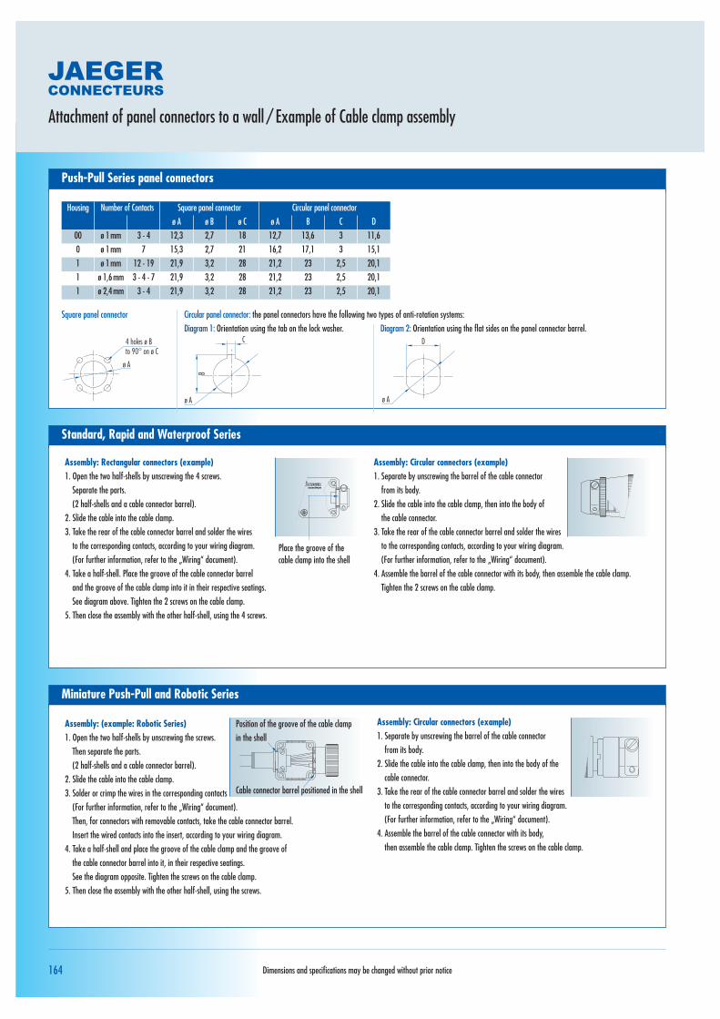
ø A ø B ø C ø A B C D00 ø 1mm 3 - 4 12,3 2,7 18 12,7 13,6 3 11,60 ø 1mm 7 15,3 2,7 21 16,2 17,1 3 15,11 ø 1mm 12 - 19 21,9 3,2 28 21,2 23 2,5 20,11 ø 1,6mm 3 - 4 - 7 21,9 3,2 28 21,2 23 2,5 20,11 ø 2,4mm 3 - 4 21,9 3,2 28 21,2 23 2,5 20,1
Assembly: (example: Robotic Series)1. Open the two half-shells by unscrewing the screws.
Then separate the parts.(2 half-shells and a cable connector barrel).
2. Slide the cable into the cable clamp.3. Solder or crimp the wires in the corresponding contacts
(For further information, refer to the „Wiring“ document). Then, for connectors with removable contacts, take the cable connector barrel. Insert the wired contacts into the insert, according to your wiring diagram.
4. Take a half-shell and place the groove of the cable clamp and the groove of the cable connector barrel into it, in their respective seatings.See the diagram opposite. Tighten the screws on the cable clamp.
5. Then close the assembly with the other half-shell, using the screws.
Assembly: Circular connectors (example)1. Separate by unscrewing the barrel of the cable connector
from its body. 2. Slide the cable into the cable clamp, then into the body of the
cable connector.3. Take the rear of the cable connector barrel and solder the wires
to the corresponding contacts, according to your wiring diagram. (For further information, refer to the „Wiring“ document).
4. Assemble the barrel of the cable connector with its body, then assemble the cable clamp. Tighten the screws on the cable clamp.
Position of the groove of the cable clampin the shell
Cable connector barrel positioned in the shell
Assembly: Rectangular connectors (example)1. Open the two half-shells by unscrewing the 4 screws.
Separate the parts. (2 half-shells and a cable connector barrel).
2. Slide the cable into the cable clamp.3. Take the rear of the cable connector barrel and solder the wires
to the corresponding contacts, according to your wiring diagram. (For further information, refer to the „Wiring“ document).
4. Take a half-shell. Place the groove of the cable connector barrel and the groove of the cable clamp into it in their respective seatings. See diagram above. Tighten the 2 screws on the cable clamp.
5. Then close the assembly with the other half-shell, using the 4 screws.
Assembly: Circular connectors (example)1. Separate by unscrewing the barrel of the cable connector
from its body.2. Slide the cable into the cable clamp, then into the body of
the cable connector.3. Take the rear of the cable connector barrel and solder the wires
to the corresponding contacts, according to your wiring diagram. (For further information, refer to the „Wiring“ document).
4. Assemble the barrel of the cable connector with its body, then assemble the cable clamp. Tighten the 2 screws on the cable clamp.
Place the groove of the cable clamp into the shell
Push-Pull Series panel connectors
Housing Number of Contacts Square panel connector Circular panel connector
4 holes ø B to 90° on ø C
Square panel connector Circular panel connector: the panel connectors have the following two types of anti-rotation systems:Diagram 1: Orientation using the tab on the lock washer. Diagram 2: Orientation using the flat sides on the panel connector barrel.
Attachment of panel connectors to a wall / Example of Cable clamp assembly
Dimensions and specifications may be changed without prior notice
Standard, Rapid and Waterproof Series
Miniature Push-Pull and Robotic Series

165
105°
140°
265°215°
115°
145°
245°
275°
3
4
57
1
6
2 2
3
71
6
4
5
12
76
5
4
3
α
621
34
7
5
α
Main key
Secondary key
Secondary key
To order types „02“, „03“ or „04“, use the part numbers of our chosen „NORMAL“ type connector, modifying it according to the model below.Model: Male panel connector, part number: 630 603 006 „NORMAL“ typebecomes 630 603 026 for a „02“ typebecomes 630 603 036 for a „03“ typebecomes 630 603 046 for a „04“ type
To facilitate identification of the connectors when wiring and locking, the barrels of the panel connector, coupler connector and the locking ring are identified by the number corresponding to the type of polarisation selected: type 02, 03 or 04.
N.B. The protective cap for the cable connector is different for keying type A and keying type B. Consult us.
Keying type A:Panel connector / Coupler connector
Keying type B:Panel connector / Coupler connector
„Normal“ TypePanel connector / Coupler connector / Female
Type „03“Panel connector / Coupler connector / Female
Type „02“Panel connector / Coupler connector / Female
Rotation of the insert in relation to the „normal“ type
α = 30° for connectors with 7 and 19 contacts α = 45° for connectors with 4 contacts α = 60° for connectors with 3, 12 and 27 contacts
Rotation of the insert in relation to type „03“
Main key identical to the „normal“ type, angular offset of the secondary keys
Type „04“Panel connector / Coupler connector / Female
For the Miniature, Industrial, Marine and Robotic series
Each series is fitted with a polarisation system. This system ensures that when connecting, the correct cable connector is connected to the corresponding panel connector and that the contacts are correctlymated. 3 other polarisation systems are available to prevent mismating between identical connectors (same series and same contact arrangement, see explanation below). This ensures that the correct cableconnector is connected to the panel connector corresponding to it.
Polarisation is provided by:- either the position of the secondary keys in relation to the main key.- or by the rotation of the insert in the housing (this rotation is performed in a clockwise direction for male connectors and anti-clockwise for female connectors).
Dimensions and specifications may be changed without prior notice
Polarisation
Conn
ector
s with
non-r
emov
able
conta
ctsCo
nnect
ors w
ith re
mova
ble co
ntacts
Acces
sorie
s Tec
hnica
l guid
es

166
A B
A B
2mm 6mm3mm 6mm4mm 6mm
2mm 4,5mm3mm 4,5mm4mm 4,5mm
1 25mm2 25mm3 25mm4 35mm5 35mm
1 25mm2 25mm3 25mm4 35mm5 35mm
Cable
Stripped part
Insulation part
Cable
Stripped part
Insulation part
ø Contact A: Stripping length
Housing B: Sheath removed
ø Contact A: Stripping length
Housing B: Sheath removed
Wiring – Conductor stripping
Standard, Rapid and Waterproof Series
Hermetic Series
These non-removable contacts are to be solderedTo avoid any error, the location of the contacts is identified by numbers on both sides of the panel connector, cable connector or coupler connector insert by numbers. For further information, refer to the „Contact arrangement“ document.
1.Remove the sheath from the cable over length B depending on the size of the housing (see table opposite).
2.Strip the wires over length A depending on the ø of the contacts (see table opposite). Before soldering, insert the stripped part of the wire into the shaft of the contact and ensure it is fully inserted and that the wire insulation is applied against the rear of the contact.
These non-removable contacts are to be solderedTo avoid any error, the location of the contacts is identified by numbers on both sides of the panel connector and on both sides of the cable connector insert. For further information, refer to the „Contact arrangement“ document.
1.Remove the sheath from the cable over length B depending on the size of the housing of the panel connector and the cable connector (see table opposite).
2.Strip the wires over length A depending on the ø of the contacts (see table opposite). Before soldering, insert the stripped part of the wire into the shaft of the contact. Check it is fully inserted via the vent hole, and that the wire insulation is applied against the rear of the contact.
Dimensions and specifications may be changed without prior notice

167
A B
L2
2
L1
1
C
ZX
X
BPower contactsø 12 mm or ø 8 mm
Pilot contactsø 1,6 mmContact bushing
Cable
Stripped part
Insulation part
Housing B: Sheath removed5 80mm
Miniature, Atto and Natto Miniature Push-Pull, Industrial, Marine, Neptunox, Robotic and Minex Series
Power Series Puissance
ø Contact A: Stripping length0,76mm 4mm
1mm 4mm1,6mm 6mm2,4mm 6mm
These contacts are either to be soldered or crimpedTo avoid any error, the location of the contacts in the insert is identified by numbers. For further information refer to the „Contact arrangement“ document
1.Remove the sheath from the cable over length „B“ depending on the size of the housing (see table opposite).
2.Strip the wires over length „A“ depending on the ø of the contacts (see table opposite). Before soldering, insert the stripped part of the wire into the shaft of the contact. Check it is fully inserted via the vent hole, and that the wire insulation is applied against the rear of the contact.
These contacts are to be crimpedTo avoid any error, the location of the contacts in the insert is identified by numbers. For further information refer to the „Contact arrangement“ document
1.Remove the sheath from the cable over length „B“ depending on the size of the housing (see table opposite).
2.Wiring of „power“ conductors ø 12mm or ø 8mm:a) fit the bushings of the contacts marked „B“ onto the wires L1, L2, making sure they are the right way round.
(see diagram opposite).b) Strip the wires L1, L2 over length „A“ depending on the ø of the contacts (see table opposite).
Before crimping, insert the stripped part of the wire into the shaft of the contact. Check it is fully inserted via the vent hole „Z“ and that the wire insulation is applied against the rear of the contact.
N.B. for cables of a smaller cross-section, remember to fit the reducer(s) in the contact shaft(s)
3.Wiring of „pilot“ conductors ø 1,6mm:a) fit the bushings of the contacts marked „C“ onto the wires 1 and 2, making sure they are the right way round. (see diagram opposite). b) Strip the wires 1 and 2 over length A depending on the ø of the contacts (see table opposite). Before crimping,
insert the stripped part of the wire into the shaft of the contact. Check it is fully inserted via the vent hole „X“ and that the wire insulation is applied against the rear of the contact.
Wiring – Conductor stripping
Dimensions and specifications may be changed without prior notice
Conn
ector
s with
non-r
emov
able
conta
ctsCo
nnect
ors w
ith re
mova
ble co
ntacts
Acces
sorie
s Tec
hnica
l guid
es
Housing B: Sheath removed00 22mm0 25mm1 22mm2 27mm3 35mm
ø Contact A: Stripping length12mm 23mm8mm 14mm
1,6mm 6mm

168
All series
Wiring – Contact soldering
Recommended equipment:We recommend a HF iron to avoid thermal shockA screwdriver type soldering iron tip 2,4 mm wide at the end and 15 mm long.In accordance with the RoHS directive, we recommend lead-free soldering.
Conductor
Panel connector
Contact shaft
Dimensions and specifications may be changed without prior notice

169
1 2
3 4
5
7
6
Contact soldering:
Wiring – Contact soldering
ImportantTo ensure the best possible solder, it is important to clean the tip before each operation using a damp sponge and carry out each operation quickly and accurately.
1.Remove the sheath from the cable and then strip the wire. See explanation above.Ensure that the strands of the wires in the stripped part are not separated.
2.Tin the stripped part of the wire with a small amount of soldering material.The solder metal must be evenly spread.
3.The result must be smooth, shiny and covered with a thin film of flux (solder metal).
4.To ensure heat transfer and stripping, place a drop of solder metal on the end of the solder tip.
5.Heat the contact shaft.
6.Insert a sufficient amount of solder metal, but not too much, into the contact shaft.
7.Insert the pre-tinned wire into the shaft of the contact, then remove the tip and allow the soldering to cool. (the parts must remain immobile while cooling)
Warningdo not leave the solder tip on the shaft of the contact for too long or you may distort the insert
Dimensions and specifications may be changed without prior notice
Conn
ector
s with
non-r
emov
able
conta
ctsCo
nnect
ors w
ith re
mova
ble co
ntacts
Acces
sorie
s Tec
hnica
l guid
es

170
5.4.3.2.1.
ø 1 mm 579 481 006 630 190 006 630 191 006 ø 1,6 mm 579 481 006 630 190 006 630 191 006ø 2,4 mm 579 481 006 630 190 006 630 191 006
Part numbers of the small crimp tool (Standard: M 22520-2 / 01 and M 22520-2 / 02)ø Contacts Tool + Positioner Tool Positionerø 0,76 mm – 630 180 006 769 100 006
ø 1 mm 579 316 006 630 180 006 630 181 006
References of the large crimp tool (Standard: M 22520-1 / 01 and M 22520-1 / 02)ø Contacts Tool + Positioner Tool Positioner
Wiring – Contact crimping
Atto and Natto Miniature Push-Pull, Miniature, Industrial, Marine, Robotic and Minex Series
Small crimp tool
Selection knob:Adjust the depth of crimping on the contactaccording to the wire cross-section. To adjustthe selector, refer to instruction number 4 ofthe „adjusting the large crimp tool“ part.
Information plate:Gives all the information required to adjust the tool correctly.
Positioner: (unlocked position)The positioner is designed for one contact ø.To crimp a contact of different ø, change the positioner.
Small crimp tool
Large crimp tool
Adjusting the large crimp tool:
Selection knob:Adjust the depth of the locator on the crimp tool according to the wire section
Indexing mark
Information plate:Gives all the information required to adjust the tool correctly
Positioner: (unlocked position)Identifies the ø of the contact to be crimped
Trigger:Unlocks the positioner
Marque d’indexation
Large crimp tool
Press the trigger to unlock thepositioner.
Turn the positioner to bring the chosen colour opposite theindexing mark. (To know whichcolour to chose, use the tableopposite or the informationplate on the crimp tool.)
Press on the positioner to lock your choice.
Remove the safety pin. Lift theselector knob and turn it to bringthe selected number opposite theindexing mark. (To know whichnumber to choose, use the tableopposite or the information plateon the crimp tool.)
Refit the safety pin.
Repeat the operation each timethe ø of the wire or the contactchanges.
Important: To adjust the positioner and the crimp tool selection knob, it must be in the open position.
Dimensions and specifications may be changed without prior notice

171
6. 7.
ø 0,76 mm 26 0,15 3ø 0,76 mm 24 0,21 – 0,24 4ø 0,76 mm 22 0,34 – 0,38 5
ø 1 mm 26 0,15 1 4ø 1 mm 24 0,21 – 0,24 2 5ø 1 mm 22 0,34 – 0,38 3 6ø 1 mm 20 0,6 4 7ø 1 mm 18 0,93 5 8
ø 1,6 mm 20 0,6 4ø 1,6 mm 18 0,93 5ø 1,6 mm 16 1,23 – 1,34 6ø 1,6 mm 14 1,82 – 1,93 7ø 2,4 mm 16 1,23 – 1,34 6ø 2,4 mm 14 1,82 – 1,93 7ø 2,4 mm 12 2,98 – 3,18 8
Instruction tableø Contacts Wire Large crimp tool Small crimp tool
AWG Cross section Positioner: Position of the Position of thein mm2 Colours index selection knob selection knob
–––
RedRedRedRedRedBlueBlueBlueBlue
YellowYellowYellow
Crimping a contact:
After removing the sheath from the cable and stripping the wires (refer tothe „stripping the contacts“ part) and adjusting the crimp tool (refer tothe „adjusting the crimp tool“ part), insert the stripped part of the wireinto the shaft of a contact. Ensure that it is fully inserted using the venthole. Fully open the crimp tool. Fully insert the contact and wire assemblyinto the orifice on the back of the tool.
Then crimp by closing the two arms of the tool completely until it reopens again. Check by looking that the contact is correctly crimped: the wire must be visible through the vent hole and the insulation on the wire must be applied against the rear of the contact.
Wiring – Contact crimping
Dimensions and specifications may be changed without prior notice
Crimped contact
Conn
ector
s with
non-r
emov
able
conta
ctsCo
nnect
ors w
ith re
mova
ble co
ntacts
Acces
sorie
s Tec
hnica
l guid
es

172
ø 8mm, ø 12mm
ø 1,6mm
1,6 mm 806 903 006 8 mm 806 903 006 12 mm 896 903 006
860 250 006 849 606 006 849 603 006
ø 1 mm 579 481 006 630 190 006 630 191 006 ø 1,6 mm 579 481 006 630 190 006 630 191 006ø 2,4 mm 579 481 006 630 190 006 630 191 006
ø 1,6 mm 20 0,6 4ø 1,6 mm 18 0,93 5ø 1,6 mm 16 1,23 – 1,34 6ø 1,6 mm 14 1,82 – 1,93 7
809 835 006 809 908 006 8mm 16mm2 7mm 14mm809 835 006 809 908 006 8mm 25mm2 7mm 14mm809 835 006 809 909 006 8mm 35mm2 9,3mm 14mm809 875 006 809 912 006 12mm 70mm2 13,8mm 23mm809 875 006 809 912 006 12mm 95mm2 13,8mm 23mm
ø Contacts Part Numbers
End for screwing the bushing tofit the ø 8 mm contacts.
End for screwing the bushing tofit the ø 1,6 mm contacts.
End for screwing the bushing tofit the ø 12 mm contacts.
Pack of 3 reducers 25 mm2→ 16 mm2
Pack of 9 reducers 35 mm2 classe 6 → 35 mm2 classe 5 Pack of 1 reducer 95 mm2→ 70 mm2
Reference of the large crimp toolø Contacts Tool + Positioner Tool Positioner
ø Contacts Wire Lare crimp tool 579 481 006USA rating Cross-section in Positioner: Position of
AWG mm2 Colours index the selection knobblueblueblueblue
ø Crimp tool Wirewithout Hexagonal die ø Contact Cross section max. sheath ø Stripping
hexagonal die WG
Wiring – Contact crimping
Power Series Puissance
Crimp tools
Reducers
Tool for fitting and removing contacts
Dimensions and specifications may be changed without prior notice

173
1. 2. 3.
Part numbers of tools for fitting and removing contactsø Contacts Part Number Identification ringø 0,76 mm 769 131 006 White
ø 1 mm 597 104 006 Redø 1,6 mm 577 454 006 Blueø 2,4 mm 577 458 006 Yellow
MINEX 597 104 10617 mixed contacts 597 104 206
Tool for fitting and removing contacts
No. 1: tool for removing the socketsNo. 2: tool for fitting the pins and socketsNo. 3: tool for removing the pinsIdentification ring
Fitting the contacts1. Fit blade No.2 in the handle of the tool
2. Position the wire and the contact inthe channel on this blade. Insert theassembly from the rear of the panelconnector or the cable connector, startingfrom the centre of the insert and working towards the outside, in the slot intended for the contact, accordingto your wiring diagram. Push the blade in as far as it will go. Withdraw the blade. Check that the contacts are correctly fitted by gently pulling oneach wire.
Removing the contacts3. Position blade No. 1 or No. 3from the front of the panel connector or the cable connectorin line with the socket or the pindepending on the blade used.Then exert axial pressure untilthe pin or the socket is releasedfrom the insert.
Fitting the contacts / Numerical index – Technical Guides
Dimensions and specifications may be changed without prior notice
809 908 006.............Wiring........................Die...............................................................................................172809 909 006.............Wiring........................Die...............................................................................................172809 912 006.............Wiring........................Die...............................................................................................172860 250 006.............Wiring........................Reducers ......................................................................................172849 606 006.............Wiring........................Reducers ......................................................................................172849 603 006.............Wiring........................Reducers ......................................................................................172806 903 006.............Wiring........................Tool for assembly and disassembly of contacts..............................172896 903 006.............Wiring........................Tool for assembly and disassembly of contacts..............................172
Part No. Series Designation Page
Numerical Index – Technical guides
Part No. Series Designation Page
579 316 006.............Wiring........................Crimp tool + positioner ................................................................170680 180 006.............Wiring........................Crimp tool ....................................................................................170769 100 006.............Wiring........................Positioner ø 0,76 mm...................................................................170680 181 006.............Wiring........................Positioner ø 1 mm........................................................................170579 481 006.............Wiring........................Crimp tool + positioner ................................................................170630 190 006.............Wiring........................Crimp tool ....................................................................................170630 191 006.............Wiring........................Positioner ø 1 mm – 1,6 mm – 2,4 mm .......................................170769 131 006.............Wiring........................Tool for assembly and disassembly of contacts..............................171597 104 006.............Wiring........................Tool for assembly and disassembly of contacts..............................171577 454 006.............Wiring........................Tool for assembly and disassembly of contacts..............................171577 458 006.............Wiring........................Tool for assembly and disassembly of contacts..............................171597 104 106.............Wiring........................Tool for assembly and disassembly of contacts..............................171597 104 206.............Wiring........................Tool for assembly and disassembly of contacts..............................171809 835 006.............Wiring........................Crimp tool ....................................................................................172809 875 006.............Wiring........................Crimp tool ....................................................................................172
Conn
ector
s with
non-r
emov
able
conta
ctsCo
nnect
ors w
ith re
mova
ble co
ntacts
Acces
sorie
s Tec
hnica
l guid
es
Fitting the contacts