Embed Size (px)
Citation preview

For further information regarding our Security Key Switches, including:
Auto Door Series(A Series)
Oval Series(O Series)
Standard Series(K Series or EZY Series)
Lift Mount(E Series)
12 Helen St VIC 3081
Ph (03) 9459 9907 Fax (03) 9459 6560Heidelberg West
www.lockitwell.com.au
“Your Key to the Right Connection”
Oval series available with optionalStainless Steel mounting plate
70mm x 115mm x 2mm
OVAL3/SS
Standard with small and large mounting platesin 4 standard switching configurations
complete with C4 cylinder.
Standard with small and large mounting platesin 4 standard switching configurations
complete with C4 cylinder.
Security fixing with removable cylinder from frontKey removal in multiple positions.
Removable (R Series)
Available in most key profiles. Cylinder removalfrom front. Key removal in multiple positions.
Wide range of lift mount key switchesFlush mount and bezel.
Pty Ltd
"R" Series available with optionalsurface mounting boxes in water
resistant or standard101mm x 101mm x 91mm
KEJB1
Hi-tech multi voltage contacts
CATALOGUE2009
Please Contact Sales - (03) 9459 9907 or visit us on www.lockitwell.com.au

FO F ON
Hi-tech multivoltage contacts
70
mm
20mm
33
mm
mm40
Key RemovalPosition Indication
Cylinder RemovalFrom Front
ywith 1.5mm Allan key
& Operating Ke
High QualitySwitch Contacts
ig ed o c ro f C be s fDes n f r ont l o ( an u ed or t pp T eri u n o e in en blo her a lications). he "A" s es ses a u ique rem vabl cyl der a ing
v t e a io . T o c ocon enien master k ying nd key recombinat ns he l ck ylinder als t l ck i c m l v ro ect m u in ro o a .serves o o n pla e a eta co er p t ing the o nt g screws f m rem v l
t do s n c l bu din Automa ic or o ommerica il g
“A” mm
Warning ;- All mains and high voltage equipment must only be connected by a licensed electrician.Earth connections must be connected where provided.All dimensions and specifications are indicative only and may change without notification.
“Auto Series”Automatic Doors
L 5 3A 52 00 AL5 50 41 0AL545021
O FF ON
peO n
m"A" = 30 m m"A" = 38 m 3"A" = 6mm 2 Stage 1 Stage Spring Return1 Stage
Note: Refer to Switch Circuits for Stage No.
Refer Below
High StrengthMetal Cover WithConceled Fixing
Points
High Strength Insulated Grivory
Cam Material
AUTO E IX T
LOCK
OPEN
o oY ur Key t the Right Connection

Digit 2"Lock Type"
A Astra
B Bilock
D Abloy
E Efco
G Kaba Modular
H Kaba Gege
K Kaba Quattro
L LockwoodP Binary Plus
S Schlage
T Lockwood Twin
V Lockwood V7
W Evva
O Other
Digit 6,7&8"Switch Circuits"
Digit 4"Key Removal"
1 Position
2 Position
3 Position
4 Position
5 Position
Two Position
1
3
2
4
OFF ON 1 N/ 1 N// O CSP I ET NR NG R UR
F O 1 / N CO F/ N N O 1 /G V RCHAN E O E
1
3
2
4
p in Re nS r g tur
7
5
3
1
8
6
4
2
Exit OpenOff Auto
position
6 = Blue
osi onp ti
AutooL ck O enpxiE t
2
4
6
8
1
3
5
7
7
5
3
3
1
21
11
9
4 5 6
2
6
10
4
8
12
1 =
5 = Black4 = d Re2 =
3 = hiteW
ON/OFF/ON
tposi ion
3
4
2
3
1
21
DOUBLE-TH OW CENTRE OFF isolated contactsR
ON/OFF/ONDOUBLE-THROW WITH CENTER OFF
2
3
3
1
21
4
6
1 2
1
3
2
3
5
Thre Pos tioe i n
Open
Auto
Off
Exit
= rang4 O e6 = l ck B a
3 = Green5 =
= hit2 W e1 = Blue
Exit
oL ck
Auto
Open
andar N / R s"St d" HORIZO PN doorL CK" N OO" O HORIZON / RP D RS
OFF ON
1
3
2
4
001
OFF ON 2 ol/ p e
3
1 2
4
E3 POSITION MULTI-ST P
61 2 316
011
006
005003
ON OFF ON/ /P ES RING RETURN TO C NTRE
007
040
9 y sp9 9 ou ecify
posi iont1 2
tposi ion
12
3
231
posit oni
posi iont
ISRA E LOW REI ERA S WLO ER
12
3
position position
OFF/ON 1 N/O 1 N/C
1
3
30 3 position
A E V R OCH NG O E WITH C MMON
2
Fou sitionr Po
1 = White3 = Red5 = reeG n7 = Blue
= low2 Yel 7
5
3
1
Auto Lo kcOpen Exit
posit oni
2
Lock
Exit
Open
Auto021
P IO U I T P4 OSIT N M LT -S E
B (SK4)WN
4 = ck Bla
8 = Blue6 = ree G n
Auto
Open
Exit
Lock
osi np tio
ExitO enp LockAuto
2
4
6
8
1
3
5
7
BWN 8 ERI 8 S ES - LOCK
041
1 = ll w Ye o
3 = Redi2 = Wh te
1 = Black
Auto
Lock
Exit
Open
UEDINGTON A TO DOORS
3 = hiteW5 = Blue 7 = re G en
low4 = Yel=2 Red
ExitoL ck OpenAuto
2
4
6
8
1
3
5
7
posit oni046
8
6
4
2
047 e t sK y Removable all posi ion
ckLo
048 ive A ndKey Capt in uto a HoldHo dl iEx t
7
5
3
1
AutoLock
posit oi n
E CO UTO DO RF A O
7
5
3
1
8
6
4
2
A tu oOpen Exit
position
O ff
237
O ff
xiE t
O enp
Auto
1 = low Yel3 = ck Bla5 = re G en
2 = White 4 =
7 =6 =
8 = Red
"HD3000" HORIZON sdoor
Open
iEx t
Off
Au ot
7
5
3
1
8
6
4
2
Au ot Op neO ff Exit
position040
6 - 7 on unit- o u2 2 n nit- o u1 4 n nit
7 - 10 on unit 4 - 1 on unit
8 - 11 on unit
OPENAUTO
62 9
I D R - IC " R E( R) O -O MAT "D SE I S
3
1
4
2
OpenExit
osi onp ti
LockAuto
5
3
1
6
4
2
Au ot Op neL cko Exit
position
OPENLOCK
VBH - GEZE
4 -K2 - BLAC1 - RED
5 - BLUE3 - YELLOW
6 -
028
7
5
3
1
8
6
4
2
Auto LockOpen iEx t
p s to i ion
LOCK
E TXI
NOPE
OAUT279
KONE ELEVATORS
LOCK XE IT
AU OT EXIT
OFF ON
posit oni
88 SERIES S D - FRB D master aticT A S m
E ix t
HoldAuto
Five P sitiono
posi onti
Exit
2
4
6
8
1
3
5
7
BESA AUT D - OS IONM O OOR 5 P IT
92 0
Open
AutoOpen Locka iP rt al
Partial oL ck
AAAA tu o
xiE t
(Protec & Disklock)
(Old Size Core)
1 2
Note: Refer to full switch circuits for other switch configurations
Engraving"Laser Etching”
Some switch types have common
engraving. If you have special requirements
Please show them in the following way at time of order.
AUTO MAN
FO FFO F ON ON
22 FO FOFF ON ON
OFF
XITEOPEN EXIT PARTIAL
OFF
OPEN
Note: Charges may apply
Optional Extras
Stainless Steel Mount
LIW Order Code“PZ11”
5mm Spacer
LIW Order Code“PC09”
(6-Pin Inline)
= Contact
= Terminal
= Spring Ret
Key
BWN (S 2 K ) BW (S 1N K )
= Link
**Note**This page only contains a selected
range of standard circuits.Almost any other circuit can be
produced on request
1
3
2
4
F oO F/ON 2 P leTSPRING RE URN
008p s ioo it n1 2
1 tageS
1 2
t ge1 S a t ge1 S a
t ge1 S a1 tageStage1 S
1 Stagetage1 Stage2 S
2 tageS
tage2 S 2 Stage 2 Stage
2 Stage 2 tageS 2 Stage
2 Stage2 tageSt ge2 S a
1 tage Stage2 S
“A Series” Cylinder Cam
LIW Code “PA05”
Di it g 5
Ele trical Rati gc n
” “5 = 1 Am ulti Volt 0 p M - The Example shown is for a Auto Series Lockwood 6-pin inline mullion mount,
with key removal in 4 positions Multi-Voltage switch.
AL545021 Digit 1
"A = Auto
rieSe s"
Digit 3
"5 = Mull ion”
ounting eM Typ
How To Order
o oY ur Key t the Right Connection

Warning ;- All mains and high voltage equipment must only be connected by a licensed electrician.Earth connections must be connected where provided.All dimensions and specifications are indicative only and may change without notification.
he R ie ue a l l e b ng c nvenient ma t r ke a T " " ser s uses a uniq remov b e cy ind r ena li o s e ying nd keyec in ti e tal op ie . The key a emov d hel c p ive in ny sw c p itr omb a on of r n pr ert s m y be r e or d a t a it hed os ion.
This eries va a l n r of in y es in a , ezel la e. s is a il b e i a va iety mount g t p includ g p nel, lift b and wall p tt a so va la l id n e of s tching c ns.I is l a i b e in a w e ra g wi onfiguratio
“ R Series”
49
mm
6mm
“B”m
m
4 m9 m
Key RemovalPosition IndicationHigh Quality
Switch Contacts
“A” mm
Standard PanelMount Fitting
Removal Cylinder
“B”
Digit 5 = 1,4,7
Digit 5 = 2
“A” Stage1 2
61mm 70mm
65mm 77mm
43mm
47mm
Panel Mount
“B”
Digit 5 = 1,4,7
Digit 5 = 2
“A” Stage1 2
71mm 81mm
75mm 88mm
43mm
47mm
Lift Mount
22
mm
“B”m
m
“A” mm
Features
Incorporates specialised lock cylinders for key removable in multiple positions.Cylinder removable from front without risk of the switch falling apart.May be master keyed into most common lock brands and high security lock systems.Electrical isolated cylinder for added safety
Cylinder RemovalFrom Front
with 1.5mm Allan key& Operating Key
High Strength Insulated Grivory
Cam Material
Optional Mounting Types
Stainless SteelLIW Order Code “PZ11”
Surface BoxLIW Order Code “KEJB1”
Water Resistant Box LIW Order Code “KEWP1”
Note: Bezel Hole
Size = 26mm
o oY ur Key t the Right Connection
Max Material Thickness 4mm
Thread Max Material Thickness 22mmCylinder Max Material Thickness 2.5mm

Digit 2"Lock Type"
A Astra
B Bilock
D Abloy
E Efco
G Kaba Modular
H Kaba Gege
K Kaba Quattro
L LockwoodP Binary Plus
S Schlage
T Lockwood Twin
V Lockwood V7
W Evva
O Other
Digit 6,7&8"Switch Circuits"
The Example shown is for a R-Series Lockwood 6-pin inline, Panel mount,
with key removal in 2 positions at 240V at 10 amp switch.
RL121003
Digit 4"Key Removal"
1 Position
2 Position
3 Position
4 Position
5 Position
6 Position
Digit 1
"Removable
Series"
7
5
3
3
1
21
11
9
4 5 6
2
6
01
4
8
21
yo c y999 u spe if o op siti n
(Protec & Disklock)
(Old Size Core)
Note: Refer to full switch circuits for other switch configurations
Engraving
Some switch types have common
engraving. If you have special requirements
Please show them in the following way at time of order.
F NOF /ON 1 N/O 1 /C
400
1
3
2
4
posit oni1 2
1 2
1
3
2
4
ON/ FF/ NO OSPRING RETURN TO CENTRE
007
RAISE ELOW R
t e1 s ag
RAISE W RLO E22
AU OT MAN OFF
ITEXOPEN
OP NE
Note: Charges may apply
Optional Mounting Types
Stainless Steel MountLIW Order Code “PZ11”
75mm X 115mm
Order with Panel Mounting Only
Surface Box MountingLIW Order Code “KEJB1”
100mm X 100mm X 100mm
Order with Panel Mounting Only
Digit 5"Electrical Rating"
1 -Mains Voltage(Standard)
AC21A 20Amp
DC1 24V-20Amp
2 -Mains Voltage/Amps AC21A 32Amp
4 -Low Current(Low Bounce)
AC21A 12V-5Amp
DC1 12V-3Amp
7 -PLC Data
Silver Button Contacts
Silver Button Contacts
DC1 24V-25Amp
Silver H-Bridge Contacts
(Low Bounce)
Gold H-Bridge Contacts
AC21A 12V-2Amp
DC1 12V-1.5Amp
Digit 3"Mounting"
1 Panel
Water Resistant Box MountingLIW Order Code “KEWP1”
100mm X 100mm X 100mm
Order with Panel Mounting Only
2 Bezel
3 Lift
Clipsal 2000 Series WallLIW Order Code “WALL”
Order with Panel Mounting
75mm X 115mm
Only
Flush Fit - StudlessLIW Order Code “DL Studless”
Diameter = 40mm Hole Size = 36mm
Order with Lift Mounting Only
5
3
2
3
1
21
110
6
4
2 stage
31
2
3 POSITION MULTI-STEP isolated contacts
1 2
1
3
2
4
56
0101 1
230
OF /O 3 POLF N E
2
2
g2 sta e
300
2
1
OFF/ON 1 N/O 1 N/CCHANGE OVER
01 51
2
60 egreed 0 egr9 d ee
0021 2
1
3
2
4
/ OFF ON 2 POLE
1
2
1
001
2
SPRING RETURN
12
008
OFF / ON 2 pole
1 2
1
3 4
2
5002
1 3
ON/OFF/ON
tposi ion
1
1
3
2
4
3
t g1 s a e
2
DOUBLE-THROW CENTRE OFF isolated contacts
070
1
2 3
OFF/ON/START
(6-Pin Inline)
SPRING RETURN
1 st e ag1 stage
1 st e ag
positionposit oni
1
3
2
4
1 2
e1 stag
pos t oni i
positionos tp i ion
1
3
2
4
1 2 3
1 stage
posit oniposition
Spring Return
Spring Return=1 Position.
Note: Specify if Captive
are Positions Required.
A
B
C
A
A
A
A
B
A
A
C
B
= Contact
= Terminal
= Spring Ret
Key
“R Series”Cylinder Cam
LIW Code “PR05”
How To Order
o oY ur Key t the Right Connection
Warning ;- All mains and high voltage equipment must only be connected by a licensed electrician.Earth connections must be connected where provided.All dimensions and specifications are indicative only and may change without notification.
EZY 2 EZY 3 EZY 4Lazy Cam Spring Return Spring Return to Centre Captive Key
EZY 11 N/O, 1 N/C changeover 1 N/O, 1 N/C changeover 1 N/O, 1 N/C changeover
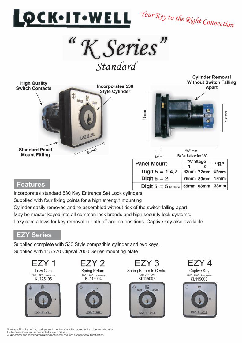
FeaturesIncorporates standard 530 Key Entrance Set Lock cylinders.
Cylinder easily removed and re-assembled without risk of the switch falling apart.
May be master keyed into all common lock brands and high security lock systems.
Lazy cam allows for key removal in both off and on positions. Captive key also available
Supplied with four fixing points for a high strength mounting
“ K Series”Incorporates 530
Style Cylinder
EZY Series
Supplied complete with 530 Style compatible cylinder and two keys.
Supplied with 115 x70 Clipsal 2000 Series mounting plate.
KL125105 KL115004 KL115007 KL115003ON / OFF / ON
Standard
49
mm
Refer Below for “A”6mm
“B”m
m
“A” mmm49 m
“B”
Digit 5 = 1,4,7
Digit 5 = 2
“A” Stage1 2
62mm 72mm
76mm 80mm
43mm
47mm
Panel Mount
Digit 5 = 5 55mm 63mm 33mmEZY-Series
o oY ur Key t the Right Connection
Cylinder RemovalWithout Switch Falling
Apart
Standard PanelMount Fitting
High QualitySwitch Contacts
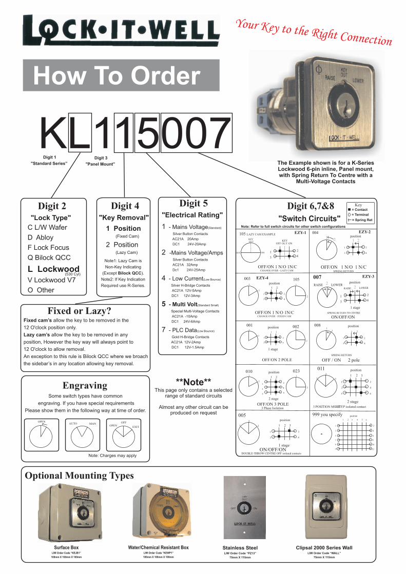
Digit 2"Lock Type"
C L/W Wafer
D Abloy
F Lock Focus
Q Bilock QCC
L LockwoodV Lockwood V7
O Other
Digit 6,7&8"Switch Circuits"
The Example shown is for a K-Series Lockwood 6-pin inline, Panel mount, with Spring Return To Centre with a
Multi-Voltage Contacts
KL115007
Digit 4"Key Removal"
1 Position
2 Position
(Fixed Cam)
(Lazy Cam)
Digit 1
"Standard Series”
7
5
3
3
1
21
11
9
4 5 6
2
6
10
4
8
12
9 o e99 y u sp cify p itioos n
Note: Refer to full switch circuits for other switch configurations
Engraving
Some switch types have common
engraving. If you have special requirements
Please show them in the following way at time of order.
OFF/ON N/O 1 1 N/C
400
1
3
2
4
i nposit o1 2
1 2
1
3
2
4
O / FF/ONN OS RI G RETURN TO CENTREP N
007
SERAI L WEO R
1 tags e
SRAI E OL WER22
AUTO MAN OFF
EXITOPEN
OPEN
Note: Charges may apply
Optional Mounting Types
Stainless SteelLIW Order Code “PZ13”
75mm X 115mm
Surface BoxLIW Order Code “KEJB1”
100mm X 100mm X 100mm
Digit 5"Electrical Rating"
1 - Mains Voltage(Standard)
AC21A 20Amp
DC1 24V-20Amp
2 -Mains Voltage/Amps AC21A 32Amp
4 - Low Current(Low Bounce)
AC21A 12V-5Amp
DC1 12V-3Amp
7 - PLC Data
Silver Button Contacts
Silver Button Contacts
Dc1 24V-25Amp
Silver H-Bridge Contacts
5 - Multi Volt(Standard Small)
Special Multi-Voltage Contacts
AC21A -10Amp
DC1 24V-6Amp
(Low Bounce)
Gold H-Bridge Contacts
AC21A 12V-2Amp
DC1 12V-1.5Amp
Water/Chemical Resistant BoxLIW Order Code “KEWP1”
100mm X 100mm X 100mm
Clipsal 2000 Series WallLIW Order Code “WALL”
75mm X 115mm
5
3
2
3
1
21
011
6
4
2 stage
31
2
3 POSITION MULTI-STEP isolated contact
1 2
1
3
2
4
56
0101 1
023
OFF/ON OL3 P E
2
2
t2 s age
003
2
1
L AM E P E105 AZY C XAM L
1
2
0021 2
1
3
2
4
O F/ON 2 POLF E
1
2
1
100
2
S RING ETURNP R
12
008
OFF / ON 2 pole
1 2
1
3 4
2
0052
1 3
ON/OFF/ON
po iti ns o
1
1
3
2
4
3
ge1 sta
2
DOUBLE-THROW CENTRE OFF isolated contacts
(530 Cyl)S RING E URNP R T
tag1 s e
si i npo t oi nposit o
1
3
2
4
1 2
si i npo t o i nposit o
npositioi nposit o
Note1: Lazy Cam is
Non-Key Indicating
( Bilock QCC).
If Key Indication
Required use R-Series.
Except
Note2:
Digit 3
"Panel Mount”
EZY-1 EZY-2
EZY-3EZY-4
= Contact
= Terminal
= Spring Ret
Key
3 Phase Isolation
1
3
2
4
OFFKEY
ONOUTOUTKEY
OFF ON
OFF/O 1 / 1N/CN N OCHANGE OVER - LAZY CAM
OFF O 1 / 1N/C/ N N O ICHANGE OVER - F XED CAM
105
Fixed or Lazy?Fixed cam’s allow the key to be removed in the
12 O'clock position only.
Lazy cam’s allow the key to be removed in any
position, However the key way will always point to
12 O'clock to allow removal.
An exception to this rule is Bilock QCC where we broach
the sidebar’s in any location allowing key removal.
**Note**This page only contains a selected
range of standard circuits
Almost any other circuit can be produced on request
How To Order
o oY ur Key t the Right Connection

Warning ;- All mains and high voltage equipment must only be connected by a licensed electrician.Earth connections must be connected where provided.All dimensions and specifications are indicative only and may change without notification.
Incorporates standard Oval lock cylinders.
Cylinder easily removed and re-assembled without switch removal.
May be master keyed into all common lock brands and high security lock systems.
Lazy cam allows for key removal in both off and on positions. Captive key available.
Electrical isolated cylinder with self extinguishing body for safety
OVAL 2 OVAL 3 OVAL 4Lazy Cam Spring Return Spring Return to Centre Captive Key
OVAL 11 N/O, 1 N/C changeover 1 N/O, 1 N/C changeover 1 N/O, 1 N/C changeover
OFF
ON
KEYOUT
ONOFF
RAISELOWER
High Strength Insulated Grivory
Material
Flame ResistantBody
High QualitySwitch Contacts
Incorporates StandardOval Cylinder Type
“O Series”
OL125105 OL115004 OL115007 OL115003
ON / OFF / ON
OVAL Series
Supplied complete with 570 Series compatible cylinder and two keys.
Supplied with 115 x70 Clipsal 2000 Series mounting plate.
Features
10mm
70
mm
1 Stage = 58 mm2 Stage = 66 mm
Note: Refer to Switch
Circuits for Stage No.
m40m
Oval
o oY ur Key t the Right Connection

How To Order
Digit 6,7&8"Switch Circuits"
The Example shown is for a O-Series Lockwood 570, Switch mount,
with Spring Return one way with a Multi-Voltage Contacts
OL415004
Digit 4"Key Removal"
1 Position
2 Position
(Fixed Cam)
(Lazy Cam)
Digit 1
"OVAL Series”
7
5
3
3
1
21
11
9
4 5 6
2
6
10
4
8
12
999 yo c fyu spe i posi onti
Note: Refer to full switch circuits for other switch configurations
/ COFF ON 1 N/O 1 N/
00 4
1
3
2
4
p ioosit n1 2
1 2
1
3
2
4
ON/OFF/ONS R N ETU TO CEN EP I G R RN TR
007
RAISE L WEO R
1 sta eg
RAISE LOW RE22
Optional Mounting Types
Stainless Steel MountLIW Order Code “PZ25”
75mm X 115mm
Surface Box MountingLIW Order Code “KEJB1-OVAL”
100mm X 100mm X 100mm
Digit 5"Electrical Rating"
1 - Mains Voltage(Standard)
AC21A 20Amp
DC1 24V-20Amp
2 -Mains Voltage/Amps AC21A 32Amp
4 - Low Current(Low Bounce)
AC21A 12V-5Amp
DC1 12V-3Amp
7 - PLC Data
Silver Button Contacts
Silver Button Contacts
Dc1 24V-25Amp
Silver H-Bridge Contacts
5 - Multi Volt(Standard Small)
Special Multi-Voltage Contacts
AC21A -10Amp
DC1 24V-6Amp
(Low Bounce)
Gold H-Bridge Contacts
AC21A 12V-2Amp
DC1 12V-1.5Amp
Clipsal 2000 Series WallLIW Order Code “OVAL WALL”
75mm X 115mm
1 2
1
3
2
4
56
0101 1
023
O F N 3 P LEF /O O
2
2
2 s geta
030
2
1
105 A Y CA E AMPL L Z M X E
1
2
0021 2
1
3
2
4
OFF ON 2 POLE/
1
2
1
001
2
R N NSP I G RETUR
12
008
OFF / ON 2 pole
1 2
1
3 4
2
0052
1 3
ON/OFF/ON
s npo itio
1
1
3
2
4
3
ta1 s ge
2
OUB E-TH OW EN E OF i ol t conD L R C TR F s a ed tacts
R NG R NSP I ETUR
1 sta eg
iposit onpo i ions t
1
3
2
4
1 2
position iposit on
po i ions t
Note1: Lazy Cam is
Non-Key Indicating
If Key Indication
Required use R-Series.
Note2:
Digit 3
"Switch Mount”
OVAL-1 OVAL-2
OVAL-3OVAL-4
= Contact
= Terminal
= Spring Ret
Key
3 Ph se Isolationa
1
3
2
4
OFFKEY
ONOUTOUTKEY
OFF ON
OFF/ON 1 N/O 1N/CE R AZCHANG OVE - L Y CAM
F O NOF /ON 1 N/ 1 /CCHANGE OVER - FIXED CAM
510
Fixed or Lazy?
Fixed cam’s allow the key to be removed in the
12 O'clock position only.
Lazy cam’s allow the key to be removed in any
position, However the key way will always point to
12 O'clock to allow removal.
**Note**This page only contains a selected
range of common circuits
Almost any other circuit can be produced on request
1 s at ge
1 stage
s1 tage 1 stage
Cylinder Fixing PinLIW Code “PO06”
Cylinder CamLIW Code “PO05”
Digit 2"Cylinder Type”
The Oval Keyswitch
uses a standard 570
style cylinder. The switch
is provided with the
cylinder retainer
o oY ur Key t the Right Connection

Hi-tech multivoltage contacts
Warning ;- All mains and high voltage equipment must only be connected by a licensed electrician.Earth connections must be connected where provided.All dimensions and specifications are indicative only and may change without notification.
Elevator“ E Series”
High Strength Brass Material
Lock WasherIncorporates YA17, YA17R
and LW3 Keyways
High QualitySwitch Contacts “A” mm
19
mm
Note: Refer to Switch Circuits for Stage No.
Refer Stage No.
“B
”m
m
“A” “B”
Bilock
Medeco
24mm
32mm
29mm
Waffer
28mmDigit 5 = 5
Digit 5 = 1,4,7Digit 5 = 2
36mm
Stage1 2
30mm 40mm
34mm 47mm
-
-
-
-
-
-
-
-
-
-
-
-
33mm
43mm
47mm
Lift Mount
Note: Bezel Mount Cutout
Size = 20.5mm
The "E" series is primarily designed for use on Lifts and elevators It meets the strict elevator regulations and can be supplied to suit standard or unique lift key codes. Circuits to suit most lift manufactures are available off the shelf.
o oY ur Key t the Right Connection

Digit 2"Lock Type"
C Wafer
M Medeco
Q Bilock QCC
R Wafer Reverse
U Medeco Removable
Digit 6,7&8"Switch Circuits"
The Example shown is for a E-Series Wafer keyed, Lift mount,
with key removal in 2 positionswith a multi-voltage switch.
EC325120
Digit 4"Key Removal"
1 Position
2 Position
3 Position
Digit 1
"Removable
Series"
Note: Please refer to the relevant circuit brochure attached or available online at www.lockitwell.com.au under the downloads section of the lift switches
Studless Surrounds TypesAvailable in Silver, Red and Black as Standard
Digit 3"Mounting"
2 Bezel
3 Lift
Two Position Circuit Brochure ID: LCIRC4
Spring Return=1 Position.
If Key Captive Required
Please Indicate Position.
Digit 5"Electrical Rating"
1 - High Voltage(Standard)
AC21A 20Amp
DC1 24V-20Amp
2 - High Voltage/Amps AC21A 32Amp
4 - Low Current(Low Bounce)
AC21A 12V-5Amp
DC1 12V-3Amp
7 - PLC Data
Silver Button Contacts
Silver Button Contacts
Dc1 24V-25Amp
Silver H-Bridge Contacts
5 - Multi Volt(Standard Small)
Special Multi-Voltage Contacts
AC21A -10Amp
DC1 24V-6Amp
(Low Bounce)
Gold H-Bridge Contacts
AC21A 12V-2Amp
DC1 12V-1.5Amp
Three PositionCircuit Brochure ID: LCIRC5
Two Position with
Spring ReturnCircuit Brochure ID: LCIRC6
Spring Return One WayCircuit Brochure ID: LCIRC7
1 2
2
2 3
2
1
1
1
2
3
Large StudlessLIW Order Code “D-Studless”
Diameter = 40mm / Hole Size = 36mm
Order with Lift Mounting Only
Small StudlessLIW Order Code “S-Studless”
Diameter = 31mm / Hole Size = 28mm
Order with Lift Mounting Only
Others colours available on request:
Medium StudlessLIW Order Code “O-Studless”
Diameter = 36mm / Hole Size = 33mm
Order with Lift Mounting Only
YA17, LW3
YA17R
**Note**Almost any circuit can be
produced on request
Dia
me
ter
Ho
le Size
Mounting Plate
Mounting Nut
Lock Nut
How To Order
o oY ur Key t the Right Connection

Stainless Steel Plates
Warning ;- All mains and high voltage equipment must only be connected by a licensed electrician.Earth connections must be connected where provided.All dimensions and specifications are indicative only and may change without notification.
CAT2008
Fire Service “003” Key
Oval 570 Style
Round 201 Style
Key Switch
Security Key Rings
Specialised Security ProductsPatented & Registered Designs
©copyright Lock It Well 2008
Quality AssuredCompany
o oY ur Key t the Right Connection
Lock It Well P/L also produce a range of Fire ServiceCylinders and Key Switches designed to be used on theFire Service LW3 003
Available in many different switching configurations.
The standard 570 Oval cylinderSupplied with one key only.
The standard 201 Round cylinderSupplied with one key only.
Security Key Ring’s are used to securekeys in group, stopping the separation ofkeys from the ring without signs of physicaltampering. Used widely in the prison and guard industry. Also used in government and council offices for car pool key control.
Lock It Well P/L have the machinery and training tomake custom specialised Stainless Steel Plates.We have a range of different techniques including: Laser Etching, Rotary Engraved, Engraved & Paint Filled, Laminated Plastic Signs and Vinyl Lettering.We also have guillotine, folding and punch tooling toallow quick turn around time for small batches.
Lock It Well P/L switches utilise the world acclaimed Kraus & Namer contact blocks. We incorporate two types ofcontact systems within our products. Self cleaning H bridges with cross wire contacts for electronic and low voltageswitching down to 30 millivolts. The other, a rigid double bridge with silver contacts providing high make and breakcapabilities. Our compact range utilises unique multi voltage contacts allowing for a wide range of currents and voltagesto be used, from PLC use to 10 amp switching. All switches have finger touch safety terminals. Standard switchingincrements are 60 degrees with 30 a degree movement on spring return functions. Ninety-degree is also available and ismandatory on lift applications. All switch blocks meet Australian and international standards and have CE certification.
Lock It Well P/L produce a large range of security switches that can be readily adapted to suit specialised requirements.Our experience includes the design and manufacture of specific purpose switches for installations including military use,Rail line signaling, Optic fibre Communication net works and high security use on Armoured vehicles. Numerous other uses including Radar tower safety devices found at all major Airport facilities in Australia, is an example of product involving both mechanical and electrical interlocking
Lock It Well P/L attained ISO 9001:2000 quality accreditation in 1996. Our commitment to quality guarantees customersatisfaction and ensures ongoing improvement to our systems. Our training program and R&D development guaranteean ongoing high standard of product and service.


![Note by Lech Walesa Regarding Further Procedure of Talks ......Note by Lech Walesa Regarding Further Procedure of Talks, [not dated] A note regarding further procedures of talks The](https://img.pdfslide.us/doc/110x75/5fa2c256f2445659142cf735/note-by-lech-walesa-regarding-further-procedure-of-talks-note-by-lech-walesa.jpg)