Embed Size (px)
Citation preview
CATALOG2018
2018.3 industrial.panasonic.com/
Thermal Management Solutions
– 1 –
Thermal Management Solutions CONTENTS
All products in this catalog comply with the RoHS Directive.
The RoHS Directive is “the Directive (2011/65/EU) on the Restriction of the Use of Certain
Hazardous Substances in Electrical and Electronic Equipment “ and its revisions.
Product Item Part Number Page
Multilayer NTC Thermistors
The NTC Thermistors 2
ERT JZ
ERT J0
ERT J1
3
Handling Precautions 11
Multilayer NTC Thermistors (Automotive Grade)
ERT J0 M
ERT J1 M16
Handling Precautions 21
“PGS” Graphite Sheets
SSM(Semi-Sealing Material)
EYG S
EYG A
EYG E
26
Minimum order 32
Handling Precautions 34
“NASBIS” Insulating Sheet
EYG Y
EYG N35
Handling Precautions 38
“Graphite-PAD” high thermal conductivity in z-directionEYG T 39
Handling Precautions 42
“Soft-PGS (Compressible Type)” PGS
with low thermal resistance
EYG S 43
Handling Precautions 47
Mar. 201803
Design and specifications are each subject to change without notice. Ask factory for the current technical specifications before purchase and/or use.
Should a safety concern arise regarding this product, please be sure to contact us immediately.
NTC Thermistors
– 2 –
T (˚C)
0–20–40 20 40 60 80 100 120 140
1000
RT/R
25
100
10
1
0.1
0.01
0.001
50006000
4000
3000
2000
B=1000
R (Ω
)
T (˚C)
2.41
2.9 3.4 3.9 4.4
125 85 50 25 0 –20 –40
10000000
1000000
100000
10000
10
1000
100
ERTJ0ER103□ B25/50=
4250
ERTJ0ER103□ B25/50=
4250
ERTJ0EG103 □A B25/85=3435
ERTJ0EG103 □A B25/85=3435 ERTJ0EP473□
B25/50=4050
ERTJ0EV104□ B 25/50
=4700
ERTJ0EV104□ B 25/50
=4700
ERTJ0EA101 □ B25/50=2800
ERTJ0EA101 □ B25/50=2800 ERTJ0ET102□ B25/50=
4500
ERTJ0ET102□ B25/50=
4500
T
1(×10 –3K–1)
ERTJ0EP473□ B25/50=4050
The NTC Thermistors
NTC Thermistors is a negative temperature coefficient resistor that significantly reduces its resistance value as the heat/ambient temperature rises. Thermistors is sintered in high-temperature (1200 °C to 1500 °C), and manufactured in various shapes. It’s comprised of 2 to 4 kinds of metal oxides: iron, nickel, cobalt, manganese and copper.
● For temperature measurement or temperature detection : Thermometer, temperature controller
● For temperature compensation : Transistor, transistor circuit, quarts oscillation circuit, and measuring instruments
● Temperature Coeffi cient of Resistance is negative, and it’s extremely large (–2.8 to –5.1 [%/°C]).
● Various shapes, especially compact size components are available.
● Selection of resistance vale is comparatively free, it’s available from several tens Ω to several hundred kΩ.
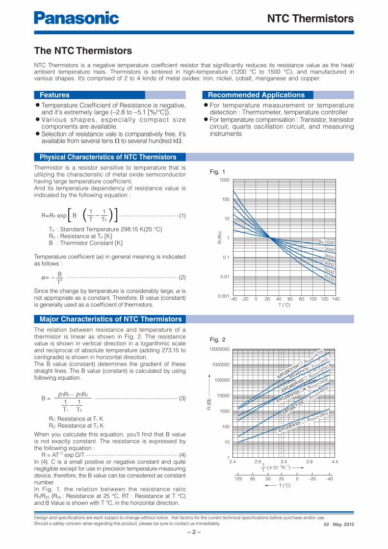
Fig. 1
Fig. 2
Thermistor is a resistor sensitive to temperature that is utilizing the characteristic of metal oxide semiconductor having large temperature coeffi cient.And its temperature dependency of resistance value is indicated by the following equation :
R=R0 exp B .....................................(1)
T0 : Standard Temperature 298.15 K(25 °C) R0 : Resistance at T0 [K] B : Thermistor Constant [K]
Temperature coeffi cient (a) in general meaning is indicated as follows :
a= .................................................................... (2)
Since the change by temperature is considerably large, a is not appropriate as a constant. Therefore, B value (constant) is generally used as a coeffi cient of thermistors.
1
T
1
T0( )[ ]
B
T2
The relation between resistance and temperature of a thermistor is linear as shown in Fig. 2. The resistance value is shown in vertical direction in a logarithmic scale and reciprocal of absolute temperature (adding 273.15 to centigrade) is shown in horizontal direction.The B value (constant) determines the gradient of these straight lines. The B value (constant) is calculated by using following equation.
B = ....................................................... (3)
R1: Resistance at T1 K R2: Resistance at T2 K
When you calculate this equation, you’ll fi nd that B value is not exactly constant. The resistance is expressed by the following equation : R = AT–C exp D/T ............................................................. (4)In (4), C is a small positive or negative constant and quite negligible except for use in precision temperature-measuring device, therefore, the B value can be considered as constant number.In Fig. 1, the relation between the resistance ratio RT/R25 (R25 : Resistance at 25 °C, RT : Resistance at T °C) and B Value is shown with T °C, in the horizontal direction.
1
T1
1
T2
knR1 – knR2
Features
Physical Characteristics of NTC Thermistors
Major Characteristics of NTC Thermistors
Recommended Applications
May. 201502
Design and specifications are each subject to change without notice. Ask factory for the current technical specifications before purchase and/or use.
Should a safety concern arise regarding this product, please be sure to contact us immediately.
Multilayer NTC Thermistors
– 3 –
E
1
R
2
T J 0 E G 1 0 3 J A
3 4 5 6 7 8 9 10 11 12
Common Code
ERT J
Product Code Type Code
NTC
Thermistors
Chip Type (SMD)
Multilayer Type
Size Code
“0201”
“0402”
“0603”
Z
0
1
Packaging
Style Code
E
V
±1%
±2%
±3%
±5%
F
G
H
J
Resistance Tolerance
Code
Nominal Resistance
R25 (Ω)
The first two digits
are significant figuresof resistance and thethird one denotes
the number of zeros
following them.
(Example)
B Value Class Code
2701 to 2800
3301 to 3400
3801 to 3900
4001 to 4100
4201 to 4300
4301 to 4400
4401 to 4500
4601 to 4700
A
G
M
P
R
S
T
VSpecial
Specification
“0201”, “0402”Pressed CarrierTapingPunched CarrierTaping(Pitch : 2 mm)
“0603”Punched CarrierTaping(Pitch : 4 mm)
Narrow ToleranceType
Standard Type
5
43
21
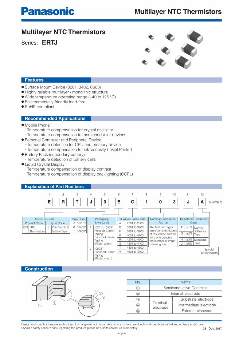
Multilayer NTC Thermistors
Series: ERTJ
Explanation of Part Numbers
Construction
Features
Recommended Applications
● Surface Mount Device (0201, 0402, 0603)● Highly reliable multilayer / monolithic structure● Wide temperature operating range (–40 to 125 °C)● Environmentally-friendly lead-free● RoHS compliant
● Mobile Phone · Temperature compensation for crystal oscillator · Temperature compensation for semiconductor devices● Personal Computer and Peripheral Device · Temperature detection for CPU and memory device · Temperature compensation for ink-viscosity (Inkjet Printer)● Battery Pack (secondary battery) · Temperature detection of battery cells● Liquid Crystal Display · Temperature compensation of display contrast · Temperature compensation of display backlighting (CCFL)
No. Name
A Semiconductive Ceramics
B Internal electrode
CTerminal
electrode
Substrate electrode
D Intermediate electrode
E External electrode
Dec. 201705
Design and specifications are each subject to change without notice. Ask factory for the current technical specifications before purchase and/or use.
Should a safety concern arise regarding this product, please be sure to contact us immediately.
Multilayer NTC Thermistors
– 4 –
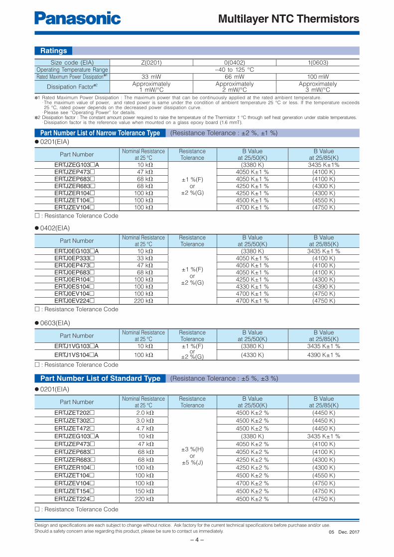
Ratings
Size code (EIA) Z(0201) 0(0402) 1(0603)Operating Temperature Range –40 to 125 °C Rated Maximum Power Dissipation✽1 33 mW 66 mW 100 mW
Dissipation Factor✽2 Approximately1 mW/°C
Approximately2 mW/°C
Approximately3 mW/°C
✽1 Rated Maximum Power Dissipation : The maximum power that can be continuously applied at the rated ambient temperature.· The maximum value of power, and rated power is same under the condition of ambient temperature 25 °C or less. If the temperature exceeds 25 °C, rated power depends on the decreased power dissipation curve.
· Please see “Operating Power” for details.✽2 Dissipation factor : The constant amount power required to raise the temperature of the Thermistor 1 °C through self heat generation under stable temperatures.
· Dissipation factor is the reference value when mounted on a glass epoxy board (1.6 mmT).
● 0201(EIA)
□ : Resistance Tolerance Code
Part NumberNominal Resistance
at 25 °CResistanceTolerance
B Valueat 25/50(K)
B Valueat 25/85(K)
ERTJZEG103□A 10 kΩ
±1 %(F)or
±2 %(G)
(3380 K) 3435 K±1%ERTJZEP473□ 47 kΩ 4050 K±1 % (4100 K)ERTJZEP683□ 68 kΩ 4050 K±1 % (4100 K)ERTJZER683□ 68 kΩ 4250 K±1 % (4300 K)ERTJZER104□ 100 kΩ 4250 K±1 % (4300 K)ERTJZET104□ 100 kΩ 4500 K±1 % (4550 K)ERTJZEV104□ 100 kΩ 4700 K±1 % (4750 K)
● 0402(EIA)
□ : Resistance Tolerance Code
Part NumberNominal Resistance
at 25 °CResistanceTolerance
B Valueat 25/50(K)
B Valueat 25/85(K)
ERTJ0EG103□A 10 kΩ
±1 %(F)or
±2 %(G)
(3380 K) 3435 K±1 %ERTJ0EP333□ 33 kΩ 4050 K±1 % (4100 K)ERTJ0EP473□ 47 kΩ 4050 K±1 % (4100 K)ERTJ0EP683□ 68 kΩ 4050 K±1 % (4100 K)ERTJ0ER104□ 100 kΩ 4250 K±1 % (4300 K)ERTJ0ES104□ 100 kΩ 4330 K±1 % (4390 K)ERTJ0EV104□ 100 kΩ 4700 K±1 % (4750 K)ERTJ0EV224□ 220 kΩ 4700 K±1 % (4750 K)
● 0603(EIA)
□ : Resistance Tolerance Code
Part NumberNominal Resistance
at 25 °CResistanceTolerance
B Valueat 25/50(K)
B Valueat 25/85(K)
ERTJ1VG103□A 10 kΩ ±1 %(F)or
±2 %(G)
(3380 K) 3435 K±1 %
ERTJ1VS104□A 100 kΩ (4330 K) 4390 K±1 %
Part Number List of Narrow Tolerance Type (Resistance Tolerance : ±2 %, ±1 %)
□ : Resistance Tolerance Code
● 0201(EIA)
Part NumberNominal Resistance
at 25 °CResistanceTolerance
B Valueat 25/50(K)
B Valueat 25/85(K)
ERTJZET202□ 2.0 kΩ
±3 %(H)or
±5 %(J)
4500 K±2 % (4450 K)
ERTJZET302□ 3.0 kΩ 4500 K±2 % (4450 K)
ERTJZET472□ 4.7 kΩ 4500 K±2 % (4450 K)
ERTJZEG103□A 10 kΩ (3380 K) 3435 K±1 %
ERTJZEP473□ 47 kΩ 4050 K±2 % (4100 K)
ERTJZEP683□ 68 kΩ 4050 K±2 % (4100 K)
ERTJZER683□ 68 kΩ 4250 K±2 % (4300 K)
ERTJZER104□ 100 kΩ 4250 K±2 % (4300 K)
ERTJZET104□ 100 kΩ 4500 K±2 % (4550 K)
ERTJZEV104□ 100 kΩ 4700 K±2 % (4750 K)
ERTJZET154□ 150 kΩ 4500 K±2 % (4750 K)
ERTJZET224□ 220 kΩ 4500 K±2 % (4750 K)
Part Number List of Standard Type (Resistance Tolerance : ±5 %, ±3 %)
Dec. 201705
Design and specifications are each subject to change without notice. Ask factory for the current technical specifications before purchase and/or use.
Should a safety concern arise regarding this product, please be sure to contact us immediately.
Multilayer NTC Thermistors
– 5 –
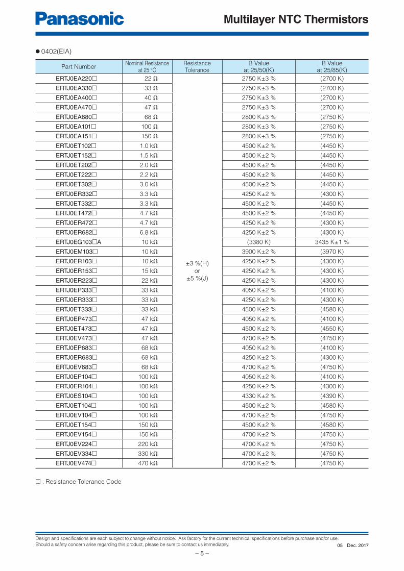
● 0402(EIA)
Part NumberNominal Resistance
at 25 °CResistanceTolerance
B Valueat 25/50(K)
B Valueat 25/85(K)
ERTJ0EA220□ 22 Ω
±3 %(H)
or
±5 %(J)
2750 K±3 % (2700 K)
ERTJ0EA330□ 33 Ω 2750 K±3 % (2700 K)
ERTJ0EA400□ 40 Ω 2750 K±3 % (2700 K)
ERTJ0EA470□ 47 Ω 2750 K±3 % (2700 K)
ERTJ0EA680□ 68 Ω 2800 K±3 % (2750 K)
ERTJ0EA101□ 100 Ω 2800 K±3 % (2750 K)
ERTJ0EA151□ 150 Ω 2800 K±3 % (2750 K)
ERTJ0ET102□ 1.0 kΩ 4500 K±2 % (4450 K)
ERTJ0ET152□ 1.5 kΩ 4500 K±2 % (4450 K)
ERTJ0ET202□ 2.0 kΩ 4500 K±2 % (4450 K)
ERTJ0ET222□ 2.2 kΩ 4500 K±2 % (4450 K)
ERTJ0ET302□ 3.0 kΩ 4500 K±2 % (4450 K)
ERTJ0ER332□ 3.3 kΩ 4250 K±2 % (4300 K)
ERTJ0ET332□ 3.3 kΩ 4500 K±2 % (4450 K)
ERTJ0ET472□ 4.7 kΩ 4500 K±2 % (4450 K)
ERTJ0ER472□ 4.7 kΩ 4250 K±2 % (4300 K)
ERTJ0ER682□ 6.8 kΩ 4250 K±2 % (4300 K)
ERTJ0EG103□A 10 kΩ (3380 K) 3435 K±1 %
ERTJ0EM103□ 10 kΩ 3900 K±2 % (3970 K)
ERTJ0ER103□ 10 kΩ 4250 K±2 % (4300 K)
ERTJ0ER153□ 15 kΩ 4250 K±2 % (4300 K)
ERTJ0ER223□ 22 kΩ 4250 K±2 % (4300 K)
ERTJ0EP333□ 33 kΩ 4050 K±2 % (4100 K)
ERTJ0ER333□ 33 kΩ 4250 K±2 % (4300 K)
ERTJ0ET333□ 33 kΩ 4500 K±2 % (4580 K)
ERTJ0EP473□ 47 kΩ 4050 K±2 % (4100 K)
ERTJ0ET473□ 47 kΩ 4500 K±2 % (4550 K)
ERTJ0EV473□ 47 kΩ 4700 K±2 % (4750 K)
ERTJ0EP683□ 68 kΩ 4050 K±2 % (4100 K)
ERTJ0ER683□ 68 kΩ 4250 K±2 % (4300 K)
ERTJ0EV683□ 68 kΩ 4700 K±2 % (4750 K)
ERTJ0EP104□ 100 kΩ 4050 K±2 % (4100 K)
ERTJ0ER104□ 100 kΩ 4250 K±2 % (4300 K)
ERTJ0ES104□ 100 kΩ 4330 K±2 % (4390 K)
ERTJ0ET104□ 100 kΩ 4500 K±2 % (4580 K)
ERTJ0EV104□ 100 kΩ 4700 K±2 % (4750 K)
ERTJ0ET154□ 150 kΩ 4500 K±2 % (4580 K)
ERTJ0EV154□ 150 kΩ 4700 K±2 % (4750 K)
ERTJ0EV224□ 220 kΩ 4700 K±2 % (4750 K)
ERTJ0EV334□ 330 kΩ 4700 K±2 % (4750 K)
ERTJ0EV474□ 470 kΩ 4700 K±2 % (4750 K)
□ : Resistance Tolerance Code
Dec. 201705
Design and specifications are each subject to change without notice. Ask factory for the current technical specifications before purchase and/or use.
Should a safety concern arise regarding this product, please be sure to contact us immediately.
Multilayer NTC Thermistors
– 6 –
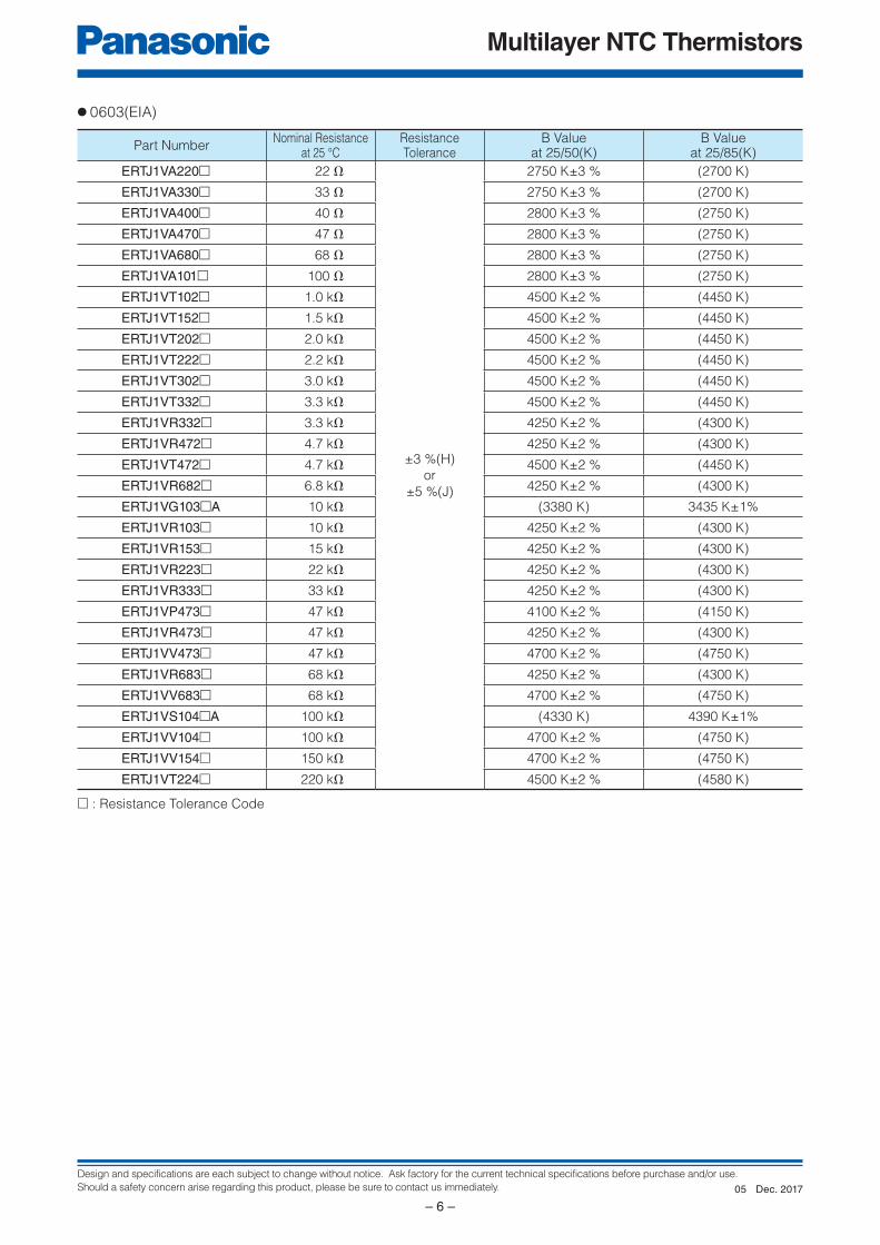
● 0603(EIA)
Part NumberNominal Resistance
at 25 °CResistanceTolerance
B Valueat 25/50(K)
B Valueat 25/85(K)
ERTJ1VA220□ 22 Ω
±3 %(H)
or
±5 %(J)
2750 K±3 % (2700 K)
ERTJ1VA330□ 33 Ω 2750 K±3 % (2700 K)
ERTJ1VA400□ 40 Ω 2800 K±3 % (2750 K)
ERTJ1VA470□ 47 Ω 2800 K±3 % (2750 K)
ERTJ1VA680□ 68 Ω 2800 K±3 % (2750 K)
ERTJ1VA101□ 100 Ω 2800 K±3 % (2750 K)
ERTJ1VT102□ 1.0 kΩ 4500 K±2 % (4450 K)
ERTJ1VT152□ 1.5 kΩ 4500 K±2 % (4450 K)
ERTJ1VT202□ 2.0 kΩ 4500 K±2 % (4450 K)
ERTJ1VT222□ 2.2 kΩ 4500 K±2 % (4450 K)
ERTJ1VT302□ 3.0 kΩ 4500 K±2 % (4450 K)
ERTJ1VT332□ 3.3 kΩ 4500 K±2 % (4450 K)
ERTJ1VR332□ 3.3 kΩ 4250 K±2 % (4300 K)
ERTJ1VR472□ 4.7 kΩ 4250 K±2 % (4300 K)
ERTJ1VT472□ 4.7 kΩ 4500 K±2 % (4450 K)
ERTJ1VR682□ 6.8 kΩ 4250 K±2 % (4300 K)
ERTJ1VG103□A 10 kΩ (3380 K) 3435 K±1%
ERTJ1VR103□ 10 kΩ 4250 K±2 % (4300 K)
ERTJ1VR153□ 15 kΩ 4250 K±2 % (4300 K)
ERTJ1VR223□ 22 kΩ 4250 K±2 % (4300 K)
ERTJ1VR333□ 33 kΩ 4250 K±2 % (4300 K)
ERTJ1VP473□ 47 kΩ 4100 K±2 % (4150 K)
ERTJ1VR473□ 47 kΩ 4250 K±2 % (4300 K)
ERTJ1VV473□ 47 kΩ 4700 K±2 % (4750 K)
ERTJ1VR683□ 68 kΩ 4250 K±2 % (4300 K)
ERTJ1VV683□ 68 kΩ 4700 K±2 % (4750 K)
ERTJ1VS104□A 100 kΩ (4330 K) 4390 K±1%
ERTJ1VV104□ 100 kΩ 4700 K±2 % (4750 K)
ERTJ1VV154□ 150 kΩ 4700 K±2 % (4750 K)
ERTJ1VT224□ 220 kΩ 4500 K±2 % (4580 K)
□ : Resistance Tolerance Code
Dec. 201705
Design and specifications are each subject to change without notice. Ask factory for the current technical specifications before purchase and/or use.
Should a safety concern arise regarding this product, please be sure to contact us immediately.
Multilayer NTC Thermistors
– 7 –
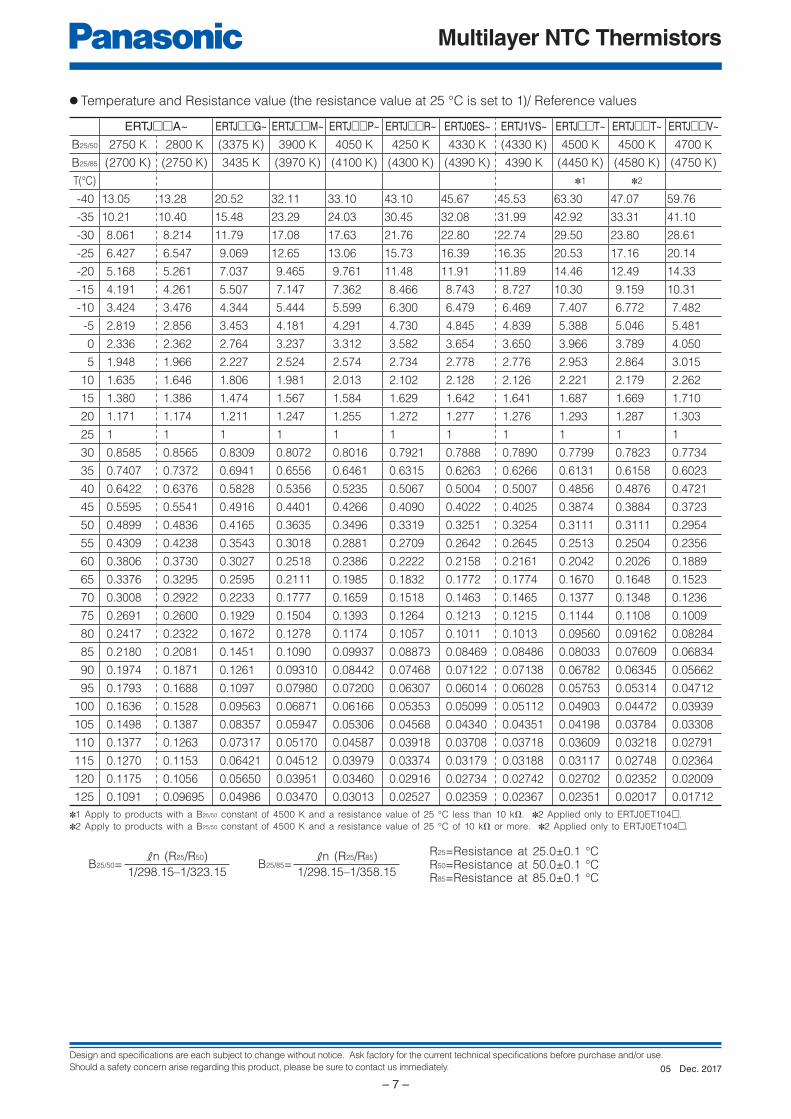
● Temperature and Resistance value (the resistance value at 25 °C is set to 1)/ Reference values
ERTJ□□A~ ERTJ□□G~ ERTJ□□M~ ERTJ□□P~ ERTJ□□R~ ERTJ0ES~ ERTJ1VS~ ERTJ□□T~ ERTJ□□T~ ERTJ□□V~
B25/50 2750 K 2800 K (3375 K) 3900 K 4050 K 4250 K 4330 K (4330 K) 4500 K 4500 K 4700 K
B25/85 (2700 K) (2750 K) 3435 K (3970 K) (4100 K) (4300 K) (4390 K) 4390 K (4450 K) (4580 K) (4750 K)
T(°C) ✽1 ✽2
-40 13.05 13.28 20.52 32.11 33.10 43.10 45.67 45.53 63.30 47.07 59.76
-35 10.21 10.40 15.48 23.29 24.03 30.45 32.08 31.99 42.92 33.31 41.10
-30 8.061 8.214 11.79 17.08 17.63 21.76 22.80 22.74 29.50 23.80 28.61
-25 6.427 6.547 9.069 12.65 13.06 15.73 16.39 16.35 20.53 17.16 20.14
-20 5.168 5.261 7.037 9.465 9.761 11.48 11.91 11.89 14.46 12.49 14.33
-15 4.191 4.261 5.507 7.147 7.362 8.466 8.743 8.727 10.30 9.159 10.31
-10 3.424 3.476 4.344 5.444 5.599 6.300 6.479 6.469 7.407 6.772 7.482
-5 2.819 2.856 3.453 4.181 4.291 4.730 4.845 4.839 5.388 5.046 5.481
0 2.336 2.362 2.764 3.237 3.312 3.582 3.654 3.650 3.966 3.789 4.050
5 1.948 1.966 2.227 2.524 2.574 2.734 2.778 2.776 2.953 2.864 3.015
10 1.635 1.646 1.806 1.981 2.013 2.102 2.128 2.126 2.221 2.179 2.262
15 1.380 1.386 1.474 1.567 1.584 1.629 1.642 1.641 1.687 1.669 1.710
20 1.171 1.174 1.211 1.247 1.255 1.272 1.277 1.276 1.293 1.287 1.303
25 1 1 1 1 1 1 1 1 1 1 1
30 0.8585 0.8565 0.8309 0.8072 0.8016 0.7921 0.7888 0.7890 0.7799 0.7823 0.7734
35 0.7407 0.7372 0.6941 0.6556 0.6461 0.6315 0.6263 0.6266 0.6131 0.6158 0.6023
40 0.6422 0.6376 0.5828 0.5356 0.5235 0.5067 0.5004 0.5007 0.4856 0.4876 0.4721
45 0.5595 0.5541 0.4916 0.4401 0.4266 0.4090 0.4022 0.4025 0.3874 0.3884 0.3723
50 0.4899 0.4836 0.4165 0.3635 0.3496 0.3319 0.3251 0.3254 0.3111 0.3111 0.2954
55 0.4309 0.4238 0.3543 0.3018 0.2881 0.2709 0.2642 0.2645 0.2513 0.2504 0.2356
60 0.3806 0.3730 0.3027 0.2518 0.2386 0.2222 0.2158 0.2161 0.2042 0.2026 0.1889
65 0.3376 0.3295 0.2595 0.2111 0.1985 0.1832 0.1772 0.1774 0.1670 0.1648 0.1523
70 0.3008 0.2922 0.2233 0.1777 0.1659 0.1518 0.1463 0.1465 0.1377 0.1348 0.1236
75 0.2691 0.2600 0.1929 0.1504 0.1393 0.1264 0.1213 0.1215 0.1144 0.1108 0.1009
80 0.2417 0.2322 0.1672 0.1278 0.1174 0.1057 0.1011 0.1013 0.09560 0.09162 0.08284
85 0.2180 0.2081 0.1451 0.1090 0.09937 0.08873 0.08469 0.08486 0.08033 0.07609 0.06834
90 0.1974 0.1871 0.1261 0.09310 0.08442 0.07468 0.07122 0.07138 0.06782 0.06345 0.05662
95 0.1793 0.1688 0.1097 0.07980 0.07200 0.06307 0.06014 0.06028 0.05753 0.05314 0.04712
100 0.1636 0.1528 0.09563 0.06871 0.06166 0.05353 0.05099 0.05112 0.04903 0.04472 0.03939
105 0.1498 0.1387 0.08357 0.05947 0.05306 0.04568 0.04340 0.04351 0.04198 0.03784 0.03308
110 0.1377 0.1263 0.07317 0.05170 0.04587 0.03918 0.03708 0.03718 0.03609 0.03218 0.02791
115 0.1270 0.1153 0.06421 0.04512 0.03979 0.03374 0.03179 0.03188 0.03117 0.02748 0.02364
120 0.1175 0.1056 0.05650 0.03951 0.03460 0.02916 0.02734 0.02742 0.02702 0.02352 0.02009
125 0.1091 0.09695 0.04986 0.03470 0.03013 0.02527 0.02359 0.02367 0.02351 0.02017 0.01712
R25=Resistance at 25.0±0.1 °CR50=Resistance at 50.0±0.1 °CR85=Resistance at 85.0±0.1 °C
B25/50=kn (R25/R50)
1/298.15–1/323.15B25/85=
kn (R25/R85)
1/298.15–1/358.15
✽1 Apply to products with a B25/50 constant of 4500 K and a resistance value of 25 °C less than 10 kΩ. ✽2 Applied only to ERTJ0ET104□.
✽2 Apply to products with a B25/50 constant of 4500 K and a resistance value of 25 °C of 10 kΩ or more. ✽2 Applied only to ERTJ0ET104□.
Dec. 201705
Design and specifications are each subject to change without notice. Ask factory for the current technical specifications before purchase and/or use.
Should a safety concern arise regarding this product, please be sure to contact us immediately.
Multilayer NTC Thermistors
– 8 –
1.0
Test Sample
0.5R0.3/Size:0201
0.5/Size:0402
Board
1.0
TestSample Unit : mm
20
45±2 45±2
Bend
ing
dis
tance
Unit : mm
R340
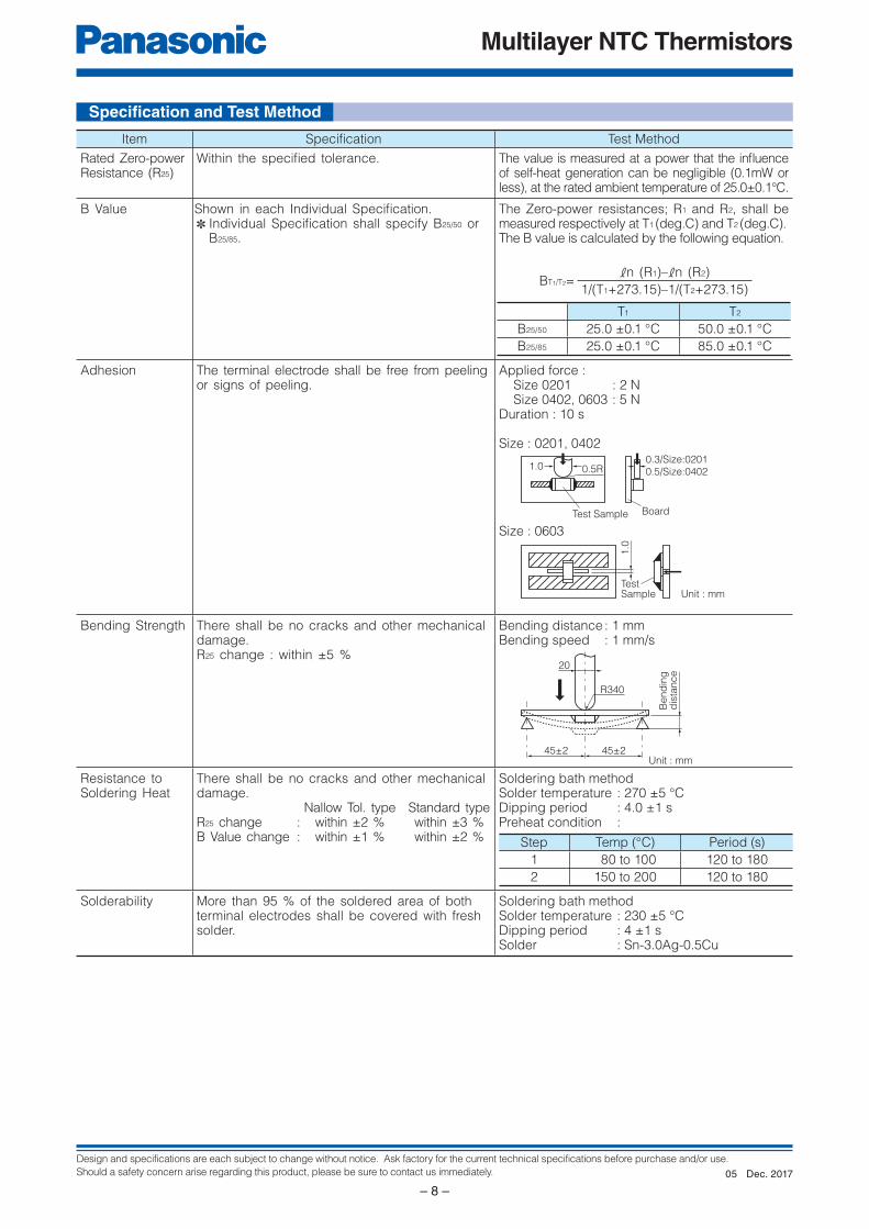
Item Specifi cation Test Method
Rated Zero-power Resistance (R25)
Within the specifi ed tolerance. The value is measured at a power that the infl uence of self-heat generation can be negligible (0.1mW or less), at the rated ambient temperature of 25.0±0.1°C.
B Value Shown in each Individual Specifi cation.✽ Individual Specifi cation shall specify B25/50 or
B25/85.
The Zero-power resistances; R1 and R2, shall be measured respectively at T1 (deg.C) and T2 (deg.C).The B value is calculated by the following equation.
BT1/T2=kn (R1)–kn (R2)
1/(T1+273.15)–1/(T2+273.15)
T1 T2
B25/50 25.0 ±0.1 °C 50.0 ±0.1 °C
B25/85 25.0 ±0.1 °C 85.0 ±0.1 °C
Adhesion The terminal electrode shall be free from peeling or signs of peeling.
Applied force : Size 0201 : 2 NSize 0402, 0603 : 5 N
Duration : 10 s
Size : 0201, 0402
Size : 0603
Bending Strength There shall be no cracks and other mechanical damage.R25 change : within ±5 %
Bending distance : 1 mmBending speed : 1 mm/s
Resistance to Soldering Heat
There shall be no cracks and other mechanical damage. Nallow Tol. type Standard typeR25 change : within ±2 % within ±3 %B Value change : within ±1 % within ±2 %
Soldering bath methodSolder temperature : 270 ±5 °CDipping period : 4.0 ±1 sPreheat condition :
Step Temp (°C) Period (s)
1 80 to 100 120 to 180
2 150 to 200 120 to 180
Solderability More than 95 % of the soldered area of both terminal electrodes shall be covered with fresh solder.
Soldering bath methodSolder temperature : 230 ±5 °CDipping period : 4 ±1 sSolder : Sn-3.0Ag-0.5Cu
Specifi cation and Test Method
Dec. 201705
Design and specifications are each subject to change without notice. Ask factory for the current technical specifications before purchase and/or use.
Should a safety concern arise regarding this product, please be sure to contact us immediately.
Multilayer NTC Thermistors
– 9 –
NTC
Rth
PMIC
AD
C
Vcc
Rth
RR L
AD converter
CPU Interface
GMR Head
NTC
Vcc
Rth R
R
R
LCD
NTC
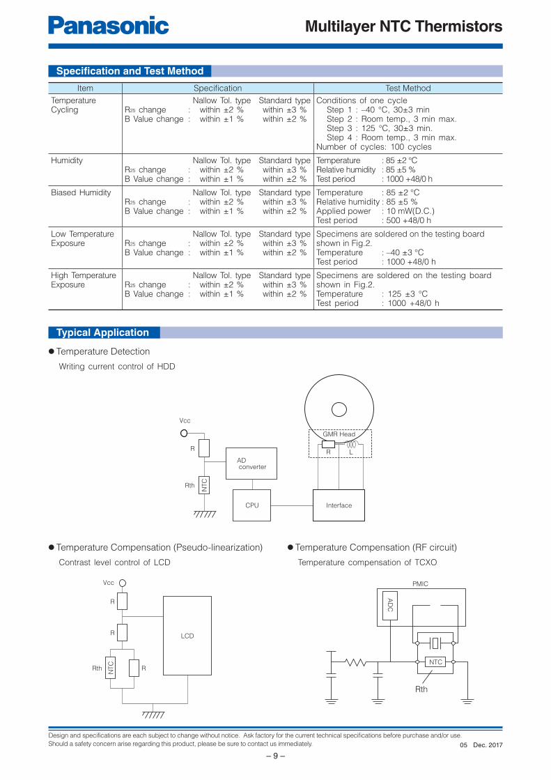
Item Specifi cation Test Method
Temperature Cycling
Nallow Tol. type Standard typeR25 change : within ±2 % within ±3 %B Value change : within ±1 % within ±2 %
Conditions of one cycleStep 1 : –40 °C, 30±3 minStep 2 : Room temp., 3 min max.Step 3 : 125 °C, 30±3 min.Step 4 : Room temp., 3 min max.
Number of cycles: 100 cycles
Humidity Nallow Tol. type Standard typeR25 change : within ±2 % within ±3 %B Value change : within ±1 % within ±2 %
Temperature : 85 ±2 °CRelative humidity : 85 ±5 %Test period : 1000 +48/0 h
Biased Humidity Nallow Tol. type Standard typeR25 change : within ±2 % within ±3 %B Value change : within ±1 % within ±2 %
Temperature : 85 ±2 °CRelative humidity : 85 ±5 %Applied power : 10 mW(D.C.)Test period : 500 +48/0 h
Low TemperatureExposure
Nallow Tol. type Standard typeR25 change : within ±2 % within ±3 %B Value change : within ±1 % within ±2 %
Specimens are soldered on the testing board shown in Fig.2.Temperature : –40 ±3 °CTest period : 1000 +48/0 h
High TemperatureExposure
Nallow Tol. type Standard typeR25 change : within ±2 % within ±3 %B Value change : within ±1 % within ±2 %
Specimens are soldered on the testing board shown in Fig.2.Temperature : 125 ±3 °CTest period : 1000 +48/0 h
Specifi cation and Test Method
Writing current control of HDD
Contrast level control of LCD Temperature compensation of TCXO
● Temperature Detection
● Temperature Compensation (Pseudo-linearization) ● Temperature Compensation (RF circuit)
Typical Application
Dec. 201705
Design and specifications are each subject to change without notice. Ask factory for the current technical specifications before purchase and/or use.
Should a safety concern arise regarding this product, please be sure to contact us immediately.
Multilayer NTC Thermistors
– 10 –
L
T
W
L1 L2
E
C
D
A
W2
W1
B100 min.
Vacant position
Top cover tape
400 min.
160 min.
Vacant position
t
P1 P2 P0K0
fD0
A
B
FW
E
Tape running directionChip component
Feeding hole Chip pocket
t2 Chip component
Feeding hole Chip pocket
fD0
P1 P2 P0 Tape running direction
EF W
B
A
t1
t1
P1 P2 P0 Tape running directiont2
Chip component
Feeding hole Chip pocket
fD0
A
B
F WE
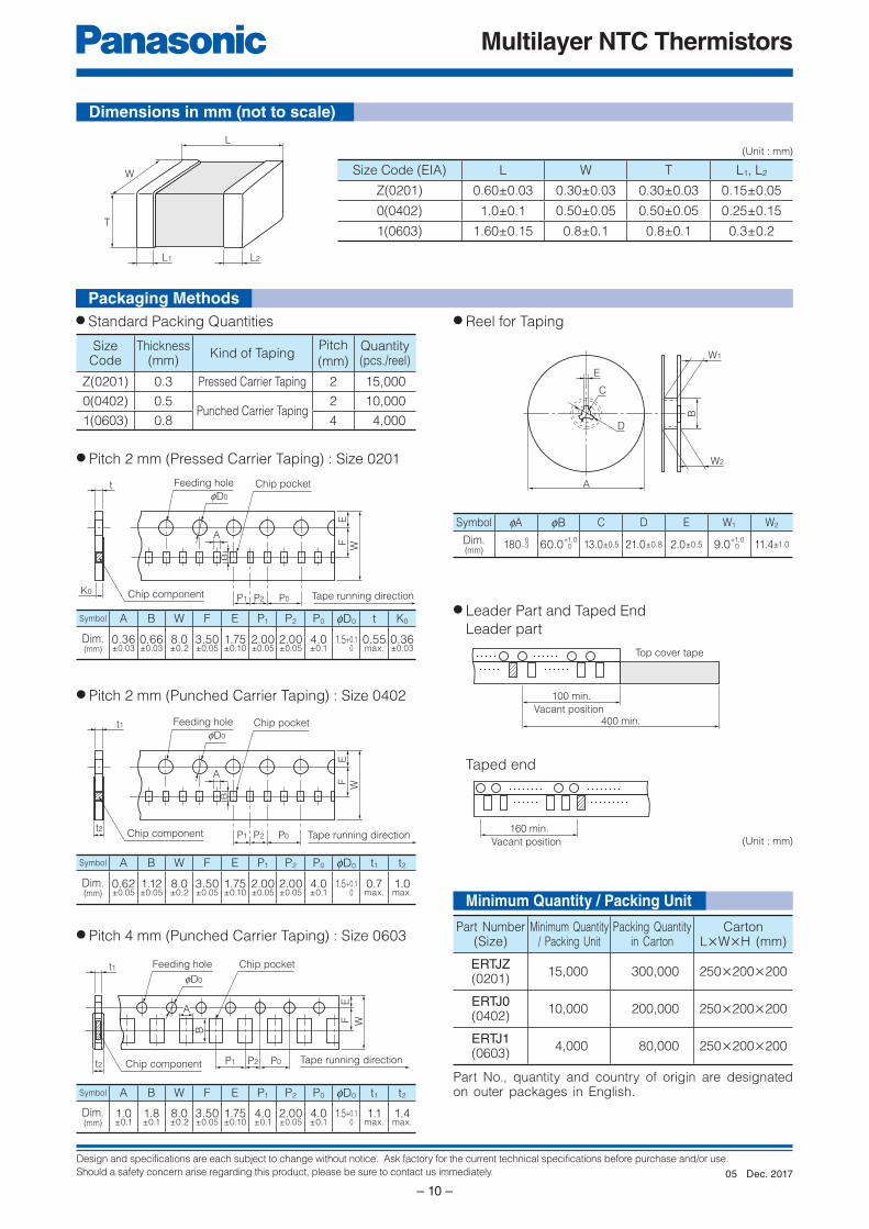
Size Code (EIA) L W T L1, L2
Z(0201) 0.60±0.03 0.30±0.03 0.30±0.03 0.15±0.05
0(0402) 1.0±0.1 0.50±0.05 0.50±0.05 0.25±0.15
1(0603) 1.60±0.15 0.8±0.1 0.8±0.1 0.3±0.2
Symbol fA fB C D E W1 W2
Dim.(mm)
180–3 60.0+1.0
13.0±0.5 21.0±0.8 2.0±0.5 9.0+1.0
11.4±1.00
Taped end
(Unit : mm)
● Pitch 2 mm (Pressed Carrier Taping) : Size 0201
● Pitch 2 mm (Punched Carrier Taping) : Size 0402
● Pitch 4 mm (Punched Carrier Taping) : Size 0603
Symbol A B W F E P1 P2 P0 fD0 t1 t2
Dim.(mm)
1.0±0.1
1.8±0.1
8.0±0.2
3.50±0.05
1.75±0.10
4.0±0.1
2.00±0.05
4.0±0.1
1.5+0.10
1.1max.
1.4max.
Symbol A B W F E P1 P2 P0 fD0 t1 t2
Dim.(mm)
0.62±0.05
1.12±0.05
8.0±0.2
3.50±0.05
1.75±0.10
2.00±0.05
2.00±0.05
4.0±0.1
1.5+0.10
0.7max.
1.0max.
Symbol A B W F E P1 P2 P0 fD0 t K0
Dim.(mm)
0.36±0.03
0.66±0.03
8.0±0.2
3.50±0.05
1.75±0.10
2.00±0.05
2.00±0.05
4.0±0.1
1.5+0.10
0.55max.
0.36±0.03
(Unit : mm)
0 0
SizeCode
Thickness(mm)
Kind of TapingPitch
(mm)Quantity(pcs./reel)
Z(0201) 0.3 Pressed Carrier Taping 2 15,000
0(0402) 0.5Punched Carrier Taping
2 10,000
1(0603) 0.8 4 4,000
Part Number(Size)
Minimum Quantity/ Packing Unit
Packing Quantity in Carton
CartonL×W×H (mm)
ERTJZ(0201)
15,000 300,000 250×200×200
ERTJ0(0402)
10,000 200,000 250×200×200
ERTJ1(0603)
4,000 80,000 250×200×200
Part No., quantity and country of origin are designated on outer packages in English.
Dimensions in mm (not to scale)
Packaging Methods
Minimum Quantity / Packing Unit
● Standard Packing Quantities ● Reel for Taping
● Leader Part and Taped End
Leader part
Dec. 201705
Design and specifications are each subject to change without notice. Ask factory for the current technical specifications before purchase and/or use.
Should a safety concern arise regarding this product, please be sure to contact us immediately.
Multilayer NTC Thermistors
– 11 –
25
100
75
Ambient temperature (°C)
Max
imum
pow
er d
issi
patio
n/ R
ated
max
imum
pow
er d
issi
patio
n (%
)
125
50
Multilayer NTC ThermistorsSeries: ERTJ
Handling Precautions
1. Circuit Design1.1 Operating Temperature and Storage Temperature
When operating a components-mounted circuit,
please be sure to observe the “Operating Temperature
Range”, written in delivery specifications. Please
remember not to use the product under the condition
that exceeds the specified maximum temperature.
Storage temperature of PCB after mounting
Thermistors, which is not operated, should be within
the specified “Storage Temperature Range” in the
delivery specifications.
1.2 Operating PowerThe electricity applied to between terminals of
Thermistors should be under the specified maximum
power dissipation.
There are possibilities of breakage and burn-out due
to excessive self-heating of Thermistors, if the power
exceeds maximum power dissipation when operating.
Please consider installing protection circuit for your
circuit to improve the safety, in case of abnormal
voltage application and so on.
Thermistors’ performance of temperature detection
would be deteriorated if self-heating occurs,
even when you use it under the maximum power
dissipation.
Please consider the maximum power dissipation and
dissipation factor.
Safety PrecautionsMultilayer NTC Thermistors (hereafter referred to as “Thermistors”) should be used for general purpose applications found in consumer electronics (audio/visual, home, office, information & communication) equipment.When subjected to severe electrical, environmental, and/or mechanical stress beyond the specifications, as noted in the Ratings and Specified Conditions section, the Thermistors’ performance may be degraded, or become failure mode, such as short circuit mode and open-circuit mode. If you use under the condition of short-circuit, heat generation of thermistors will occur by running large current due to application of voltage. There are possibilities of smoke emission, substrate burn-out, and, in the worst case, fire.For products which require higher safety levels, please carefully consider how a single malfunction can affect your product. In order to ensure the safety in the case of a single malfunction, please design products with fail-safe, such as setting up protecting circuits, etc.
● For the following applications and conditions, please contact us for product of special specification not found in this document.· When your application may have difficulty complying with the safety or handling precautions specified below.· High-quality and high-reliability required devices that have possibility of causing hazardous conditions, such as
death or injury (regardless of directly or indirectly), due to failure or malfunction of the product.
1 Aircraft and Aerospace Equipment (artificial satellite, rocket, etc.)2 Submarine Equipment (submarine repeating equipment, etc.)3 Transportation Equipment (motor vehicles, airplanes, trains, ship, traffic signal controllers, etc.)4 Power Generation Control Equipment (atomic power, hydroelectric power, thermal power plant control system, etc.)5 Medical Equipment (life-support equipment, pacemakers, dialysis controllers, etc.)6 Information Processing Equipment (large scale computer systems, etc.)7 Electric Heating Appliances, Combustion devices (gas fan heaters, oil fan heaters, etc.)8 Rotary Motion Equipment9 Security SystemsJ And any similar types of equipment
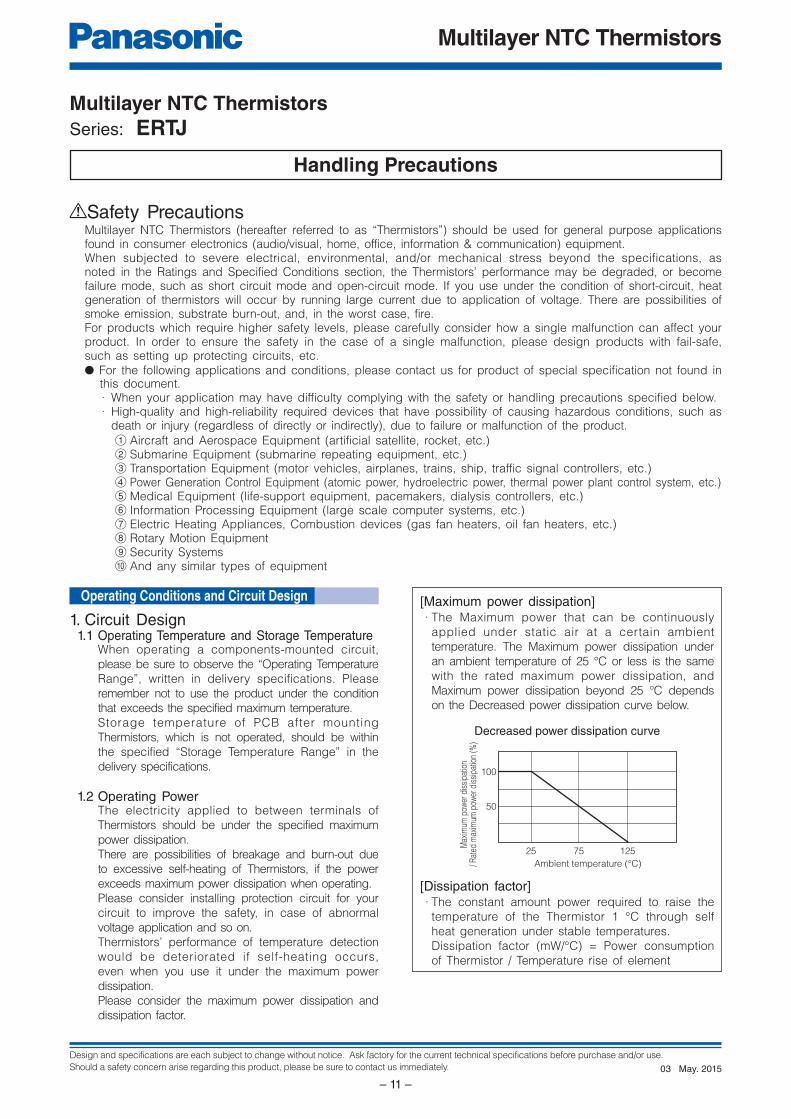
[Maximum power dissipation] · The Maximum power that can be continuously
applied under static air at a certain ambient
temperature. The Maximum power dissipation under
an ambient temperature of 25 °C or less is the same
with the rated maximum power dissipation, and
Maximum power dissipation beyond 25 °C depends
on the Decreased power dissipation curve below.
[Dissipation factor] · The constant amount power required to raise the
temperature of the Thermistor 1 °C through self
heat generation under stable temperatures.
Dissipation factor (mW/°C) = Power consumption
of Thermistor / Temperature rise of element
Decreased power dissipation curve
Operating Conditions and Circuit Design
May. 201503
Design and specifications are each subject to change without notice. Ask factory for the current technical specifications before purchase and/or use.
Should a safety concern arise regarding this product, please be sure to contact us immediately.
Multilayer NTC Thermistors
– 12 –
ab
c
LandSMD
Solder resist
(a) Excessive amount (b) Proper amount (c) Insufficient amount
Solder resistLand
Portion to beexcessively soldered
A lead wire ofRetro-fittedcomponent
Solderingiron
Solder(Ground solder)
Chassis
Electrode pattern
Solder resist
Solder resist
Solder resistThe lead wire of a component with lead wires
1.3 Environmental RestrictionsThe Thermistors shall not be operated and/or
stored under the following conditions.
(1) Environmental conditions
(a) Under direct exposure to water or salt water
(b) Under conditions where water can condense
and/or dew can form
(c) Under conditions containing corrosive gases
such as hydrogen sulfide, sulfurous acid,
chlorine and ammonia
(2) Mechanical conditions
The place where vibration or impact that
exceeds specified conditions written in delivery
specification is loaded.
1.4 Measurement of ResistanceThe resistance of the Thermistors varies depending
on ambient temperatures and self-heating. To
measure the resistance value when examining circuit
configuration and conducting receiving inspection
and so on, the following points should be taken into
consideration:
1 Measurement temp : 25±0.1 °CMeasurement in l iquid (si l icon oil, etc.) is
recommended for a stable measurement temperature.
2 Power : 0.10 mW max.4 terminal measurement with a constant-current
power supply is recommended.
2. Design of Printed Circuit Board2.1 Selection of Printed Circuit Boards
There is a possibility of performance deterioration
by heat shock (temperature cycles), which causes
cracks, from alumina substrate.
Please confirm that the substrate you use does
not deteriorate the Thermistors’ quality.
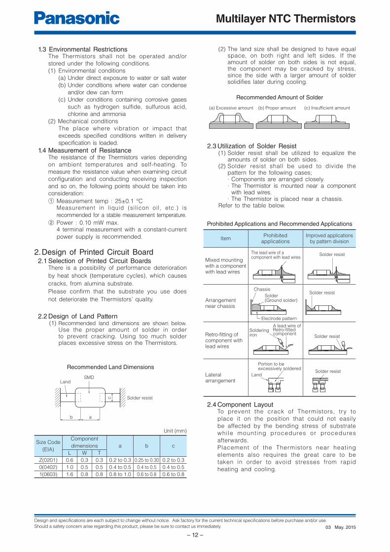
2.2 Design of Land Pattern(1) Recommended land dimensions are shown below.
Use the proper amount of solder in order to prevent cracking. Using too much solder places excessive stress on the Thermistors.
Unit (mm)
Size Code
(EIA)
Component
dimensions a b c
L W T
Z(0201) 0.6 0.3 0.3 0.2 to 0.3 0.25 to 0.30 0.2 to 0.3
0(0402) 1.0 0.5 0.5 0.4 to 0.5 0.4 to 0.5 0.4 to 0.5
1(0603) 1.6 0.8 0.8 0.8 to 1.0 0.6 to 0.8 0.6 to 0.8
Recommended Land Dimensions
(2) The land size shall be designed to have equal space, on both right and left sides. If the amount of solder on both sides is not equal, the component may be cracked by stress, since the side with a larger amount of solder solidifies later during cooling.
Recommended Amount of Solder
2.3 Utilization of Solder Resist(1) Solder resist shall be utilized to equalize the
amounts of solder on both sides.(2) Solder resist shall be used to divide the
pattern for the following cases;· Components are arranged closely.· The Thermistor is mounted near a component
with lead wires.· The Thermistor is placed near a chassis.
Refer to the table below.
Prohibited Applications and Recommended Applications
ItemProhibited
applicationsImproved applications
by pattern division
Mixed mounting with a component with lead wires
Arrangement near chassis
Retro-fi tting of component with lead wires
Lateral arrangement
2.4 Component LayoutTo prevent the crack of Thermistors, try to
place it on the position that could not easily
be affected by the bending stress of substrate
whi le mounting procedures or procedures
afterwards.
Placement of the Thermistors near heating
elements also requires the great care to be
taken in order to avoid stresses from rapid
heating and cooling.
May. 201503
Design and specifications are each subject to change without notice. Ask factory for the current technical specifications before purchase and/or use.
Should a safety concern arise regarding this product, please be sure to contact us immediately.
Multilayer NTC Thermistors
– 13 –
AB
C
E
D
Slit
Magnitude of stress A>B=C>D>E
Perforation
Supportingpin
SupportingpinCrackSeparation of Solder
Crack
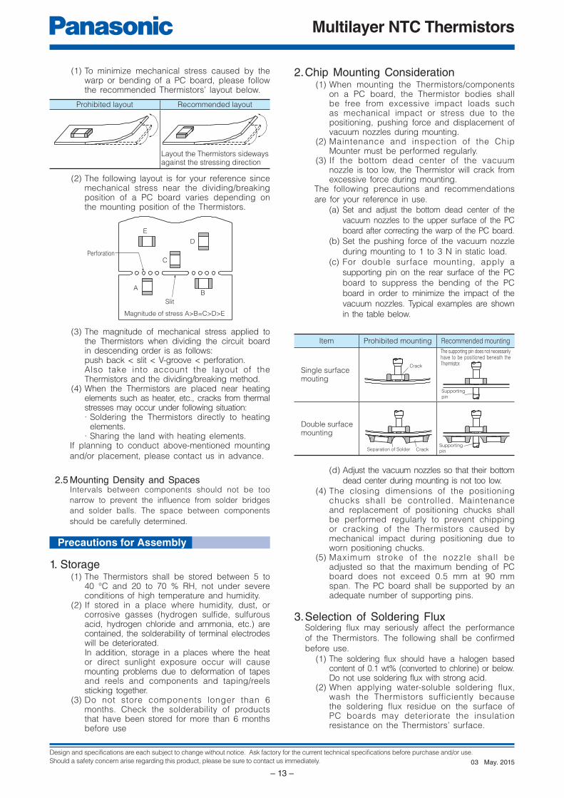
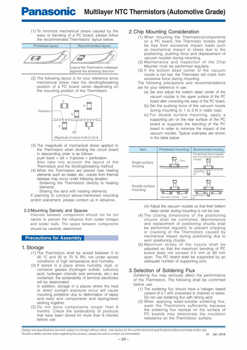
(1) To minimize mechanical stress caused by the warp or bending of a PC board, please follow the recommended Thermistors’ layout below.
(2) The following layout is for your reference since mechanical stress near the dividing/breaking position of a PC board varies depending on the mounting position of the Thermistors.
(3) The magnitude of mechanical stress applied to the Thermistors when dividing the circuit board in descending order is as follows:
push back < slit < V-groove < perforation. Also take into account the layout of the
Thermistors and the dividing/breaking method.(4) When the Thermistors are placed near heating
elements such as heater, etc., cracks from thermal stresses may occur under following situation:· Soldering the Thermistors directly to heating
elements.· Sharing the land with heating elements.
If planning to conduct above-mentioned mounting
and/or placement, please contact us in advance.
2.5 Mounting Density and SpacesIntervals between components should not be too
narrow to prevent the influence from solder bridges
and solder balls. The space between components
should be carefully determined.
1. Storage(1) The Thermistors shall be stored between 5 to
40 °C and 20 to 70 % RH, not under severe conditions of high temperature and humidity.
(2) If stored in a place where humidity, dust, or corrosive gasses (hydrogen sulfide, sulfurous acid, hydrogen chloride and ammonia, etc.) are contained, the solderability of terminal electrodes will be deteriorated.
In addition, storage in a places where the heat or direct sunlight exposure occur will cause mounting problems due to deformation of tapes and reels and components and taping/reels sticking together.
(3) Do not store components longer than 6 months. Check the solderability of products that have been stored for more than 6 months before use
2. Chip Mounting Consideration(1) When mounting the Thermistors/components
on a PC board, the Thermistor bodies shall be free from excessive impact loads such as mechanical impact or stress due to the positioning, pushing force and displacement of vacuum nozzles during mounting.
(2) Maintenance and inspection of the Chip Mounter must be performed regularly.
(3) If the bottom dead center of the vacuum nozzle is too low, the Thermistor will crack from excessive force during mounting.
The following precautions and recommendations
are for your reference in use.
(a) Set and adjust the bottom dead center of the
vacuum nozzles to the upper surface of the PC
board after correcting the warp of the PC board.
(b) Set the pushing force of the vacuum nozzle
during mounting to 1 to 3 N in static load.
(c) For double surface mounting, apply a
supporting pin on the rear surface of the PC
board to suppress the bending of the PC
board in order to minimize the impact of the
vacuum nozzles. Typical examples are shown
in the table below.
Item Prohibited mounting Recommended mounting
Single surface mouting
The supporting pin does not necessarily have to be positioned beneath the Thermistor.
Double surface mounting
(d) Adjust the vacuum nozzles so that their bottom
dead center during mounting is not too low.
(4) The closing dimensions of the positioning chucks shall be controlled. Maintenance and replacement of positioning chucks shall be performed regularly to prevent chipping or cracking of the Thermistors caused by mechanical impact during positioning due to worn positioning chucks.
(5) Maximum stroke of the nozzle shall be adjusted so that the maximum bending of PC board does not exceed 0.5 mm at 90 mm span. The PC board shall be supported by an adequate number of supporting pins.
3. Selection of Soldering FluxSoldering flux may seriously affect the performance
of the Thermistors. The following shall be confirmed
before use.
(1) The soldering flux should have a halogen based content of 0.1 wt% (converted to chlorine) or below.
Do not use soldering flux with strong acid.(2) When applying water-soluble soldering flux,
wash the Thermistors sufficiently because the soldering flux residue on the surface of PC boards may deteriorate the insulation resistance on the Thermistors’ surface.
Prohibited layout Recommended layout
Layout the Thermistors sideways against the stressing direction
Precautions for Assembly
May. 201503
Design and specifications are each subject to change without notice. Ask factory for the current technical specifications before purchase and/or use.
Should a safety concern arise regarding this product, please be sure to contact us immediately.
Multilayer NTC Thermistors
– 14 –
Time
Gradualcooling
5
Heating3
Peak4
Temp. rise
△T 2
Preheating1
60 sec max.60 to 120 sec
Tem
pera
ture
(°C
)
260
220
180
140
△T
Preheating
Gradual cooling
60 to 120 sec 3 sec max.
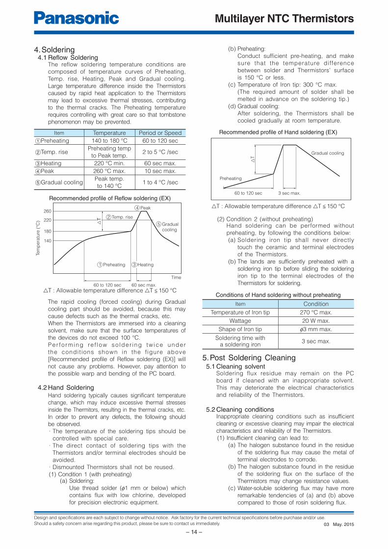
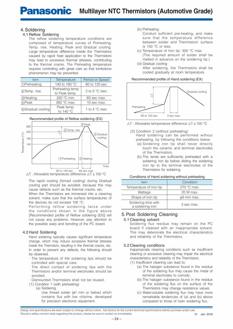
4. Soldering4.1 Reflow Soldering
The reflow soldering temperature conditions are
composed of temperature curves of Preheating,
Temp. rise, Heating, Peak and Gradual cooling.
Large temperature difference inside the Thermistors
caused by rapid heat application to the Thermistors
may lead to excessive thermal stresses, contributing
to the thermal cracks. The Preheating temperature
requires controlling with great care so that tombstone
phenomenon may be prevented.
Item Temperature Period or Speed
1Preheating 140 to 180 °C 60 to 120 sec
2Temp. risePreheating temp
to Peak temp.2 to 5 °C /sec
3Heating 220 °C min. 60 sec max.
4Peak 260 °C max. 10 sec max.
5Gradual coolingPeak temp.
to 140 °C1 to 4 °C /sec
Recommended profi le of Refl ow soldering (EX)
△T : Allowable temperature difference △T < 150 °C
The rapid cooling (forced cooling) during Gradual
cooling part should be avoided, because this may
cause defects such as the thermal cracks, etc.
When the Thermistors are immersed into a cleaning
solvent, make sure that the surface temperatures of
the devices do not exceed 100 °C.
Per fo rming re f low so lder ing tw ice under
the condit ions shown in the f igure above
[Recommended profile of Reflow soldering (EX)] will
not cause any problems. However, pay attention to
the possible warp and bending of the PC board.
4.2 Hand SolderingHand soldering typically causes significant temperature
change, which may induce excessive thermal stresses
inside the Thermitors, resulting in the thermal cracks, etc.
In order to prevent any defects, the following should
be observed.
· The temperature of the soldering tips should be
controlled with special care.
· The direct contact of soldering tips with the
Thermistors and/or terminal electrodes should be
avoided.
· Dismounted Thermistors shall not be reused.
(1) Condition 1 (with preheating)(a) Soldering:
Use thread solder (f1 mm or below) which
contains flux with low chlorine, developed
for precision electronic equipment.
(b) Preheating:
Conduct sufficient pre-heating, and make
sure that the temperature difference
between solder and Thermistors’ surface
is 150 °C or less.
(c) Temperature of Iron tip: 300 °C max.
(The required amount of solder shall be
melted in advance on the soldering tip.)
(d) Gradual cooling:
After soldering, the Thermistors shall be
cooled gradually at room temperature.
Recommended profi le of Hand soldering (EX)
△T : Allowable temperature difference △T < 150 °C
(2) Condition 2 (without preheating)Hand soldering can be performed without
preheating, by following the conditions below:
(a) Soldering iron tip shall never directly
touch the ceramic and terminal electrodes
of the Thermistors.
(b) The lands are sufficiently preheated with a
soldering iron tip before sliding the soldering
iron tip to the terminal electrodes of the
Thermistors for soldering.
Conditions of Hand soldering without preheating
Item Condition
Temperature of Iron tip 270 °C max.
Wattage 20 W max.
Shape of Iron tip f3 mm max.
Soldering time witha soldering iron
3 sec max.
5. Post Soldering Cleaning5.1 Cleaning solvent
Soldering flux residue may remain on the PC
board if cleaned with an inappropriate solvent.
This may deteriorate the electrical characteristics
and reliability of the Thermistors.
5.2 Cleaning conditionsInappropriate cleaning conditions such as insufficient
cleaning or excessive cleaning may impair the electrical
characteristics and reliability of the Thermistors.
(1) Insufficient cleaning can lead to:
(a) The halogen substance found in the residue
of the soldering flux may cause the metal of
terminal electrodes to corrode.
(b) The halogen substance found in the residue
of the soldering flux on the surface of the
Thermistors may change resistance values.
(c) Water-soluble soldering flux may have more
remarkable tendencies of (a) and (b) above
compared to those of rosin soldering flux.
May. 201503
Design and specifications are each subject to change without notice. Ask factory for the current technical specifications before purchase and/or use.
Should a safety concern arise regarding this product, please be sure to contact us immediately.
Multilayer NTC Thermistors
– 15 –
Supporting pinSeparated, Crack
Check pinCheck pin
Bending Torsion
PC board splitting jig
V-groovePC board
Outline of Jig
PCboard
Chipcomponent
Loadingpoint
V-groove
Loading direction
PCboard Chip component
Loadingpoint
V-groove
Loading direction
Floor
Crack
Mounted PCB
Crack
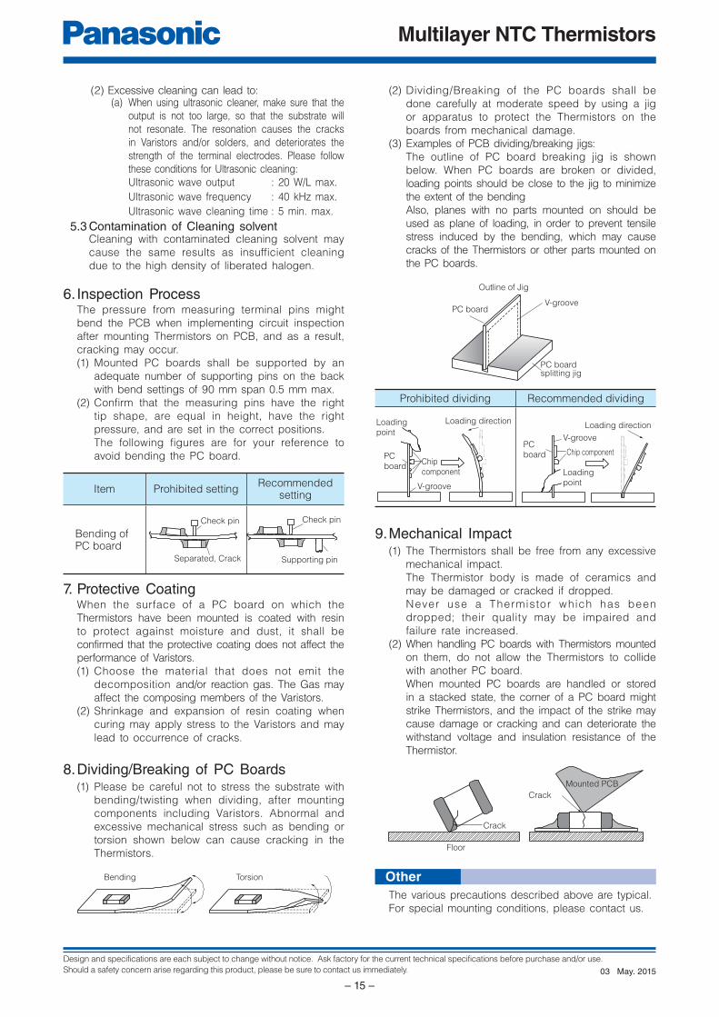
(2) Excessive cleaning can lead to:(a) When using ultrasonic cleaner, make sure that the
output is not too large, so that the substrate will
not resonate. The resonation causes the cracks
in Varistors and/or solders, and deteriorates the
strength of the terminal electrodes. Please follow
these conditions for Ultrasonic cleaning:
Ultrasonic wave output : 20 W/L max.
Ultrasonic wave frequency : 40 kHz max.
Ultrasonic wave cleaning time : 5 min. max.
5.3 Contamination of Cleaning solventCleaning with contaminated cleaning solvent may
cause the same results as insufficient cleaning
due to the high density of liberated halogen.
6. Inspection ProcessThe pressure from measuring terminal pins might
bend the PCB when implementing circuit inspection
after mounting Thermistors on PCB, and as a result,
cracking may occur.
(1) Mounted PC boards shall be supported by an
adequate number of supporting pins on the back
with bend settings of 90 mm span 0.5 mm max.
(2) Confi rm that the measuring pins have the right
tip shape, are equal in height, have the right
pressure, and are set in the correct positions.
The following figures are for your reference to
avoid bending the PC board.
Item Prohibited settingRecommended
setting
Bending ofPC board
7. Protective CoatingWhen the surface of a PC board on which the
Thermistors have been mounted is coated with resin
to protect against moisture and dust, it shall be
confirmed that the protective coating does not affect the
performance of Varistors.
(1) Choose the material that does not emit the
decomposition and/or reaction gas. The Gas may
affect the composing members of the Varistors.
(2) Shrinkage and expansion of resin coating when
curing may apply stress to the Varistors and may
lead to occurrence of cracks.
8. Dividing/Breaking of PC Boards(1) Please be careful not to stress the substrate with
bending/twisting when dividing, after mounting
components including Varistors. Abnormal and
excessive mechanical stress such as bending or
torsion shown below can cause cracking in the
Thermistors.
(2) Dividing/Breaking of the PC boards shall be
done carefully at moderate speed by using a jig
or apparatus to protect the Thermistors on the
boards from mechanical damage.
(3) Examples of PCB dividing/breaking jigs:
The outline of PC board breaking jig is shown
below. When PC boards are broken or divided,
loading points should be close to the jig to minimize
the extent of the bending
Also, planes with no parts mounted on should be
used as plane of loading, in order to prevent tensile
stress induced by the bending, which may cause
cracks of the Thermistors or other parts mounted on
the PC boards.
Prohibited dividing Recommended dividing
9. Mechanical Impact(1) The Thermistors shall be free from any excessive
mechanical impact.
The Thermistor body is made of ceramics and
may be damaged or cracked if dropped.
Never use a Thermistor which has been
dropped; their quality may be impaired and
failure rate increased.
(2) When handling PC boards with Thermistors mounted
on them, do not allow the Thermistors to collide
with another PC board.
When mounted PC boards are handled or stored
in a stacked state, the corner of a PC board might
strike Thermistors, and the impact of the strike may
cause damage or cracking and can deteriorate the
withstand voltage and insulation resistance of the
Thermistor.
The various precautions described above are typical.
For special mounting conditions, please contact us.
Other
May. 201503
Design and specifications are each subject to change without notice. Ask factory for the current technical specifications before purchase and/or use.
Should a safety concern arise regarding this product, please be sure to contact us immediately.
Multilayer NTC Thermistors (Automotive Grade)
– 16 –
E
1
R
2
T J 0 E G 1 0 3 F M
3 4 5 6 7 8 9 10 11 12
Common Code
ERT J
Product Code Type Code
NTC
Thermistors
Chip Type (SMD)
Multilayer Type
Size Code
“0402”
“0603”
0
1
Packaging
Style Code
E
V
±1%
±2%
±3%
±5%
F
G
H
J
Resistance Tolerance
Code
Nominal Resistance
R25 (Ω)
The first two digits
are significant figuresof resistance and thethird one denotes
the number of zeros
following them.
(Example)
B Value Class Code
2701 to 2800
3301 to 3400
3801 to 3900
4001 to 4100
4201 to 4300
4301 to 4400
4401 to 4500
4601 to 4700
A
G
M
P
R
S
T
VAutomotivecomponent
“0402”Pressed CarrierTapingPunched CarrierTaping(Pitch : 2 mm)
“0603”Punched CarrierTaping(Pitch : 4 mm)
Narrow ToleranceType
Standard Type
M
5
43
21
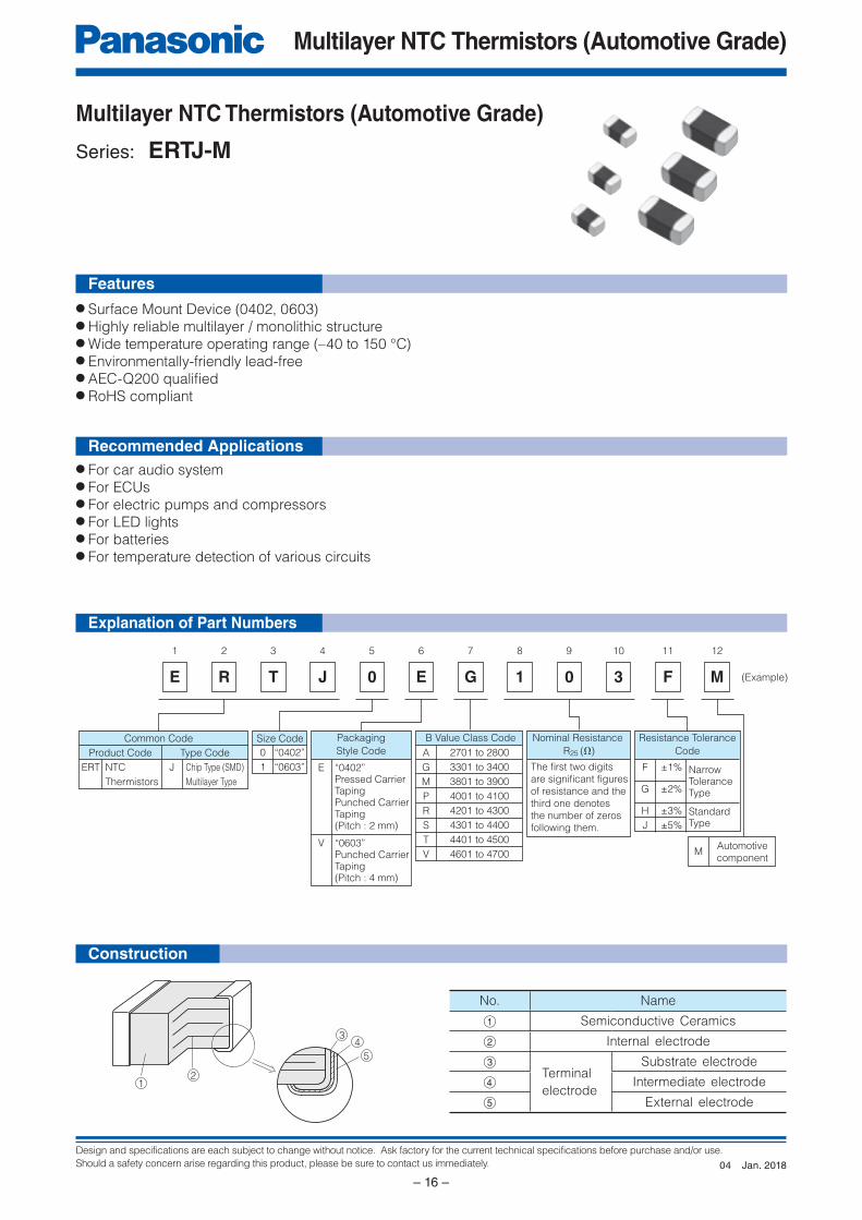
Multilayer NTC Thermistors (Automotive Grade)
Series: ERTJ-M
Explanation of Part Numbers
Construction
Features
Recommended Applications
● Surface Mount Device (0402, 0603)● Highly reliable multilayer / monolithic structure● Wide temperature operating range (–40 to 150 °C)● Environmentally-friendly lead-free● AEC-Q200 qualifi ed● RoHS compliant
● For car audio system● For ECUs● For electric pumps and compressors● For LED lights● For batteries● For temperature detection of various circuits
No. Name
A Semiconductive Ceramics
B Internal electrode
CTerminal
electrode
Substrate electrode
D Intermediate electrode
E External electrode
Jan. 201804
Design and specifications are each subject to change without notice. Ask factory for the current technical specifications before purchase and/or use.
Should a safety concern arise regarding this product, please be sure to contact us immediately.
Multilayer NTC Thermistors (Automotive Grade)
– 17 –
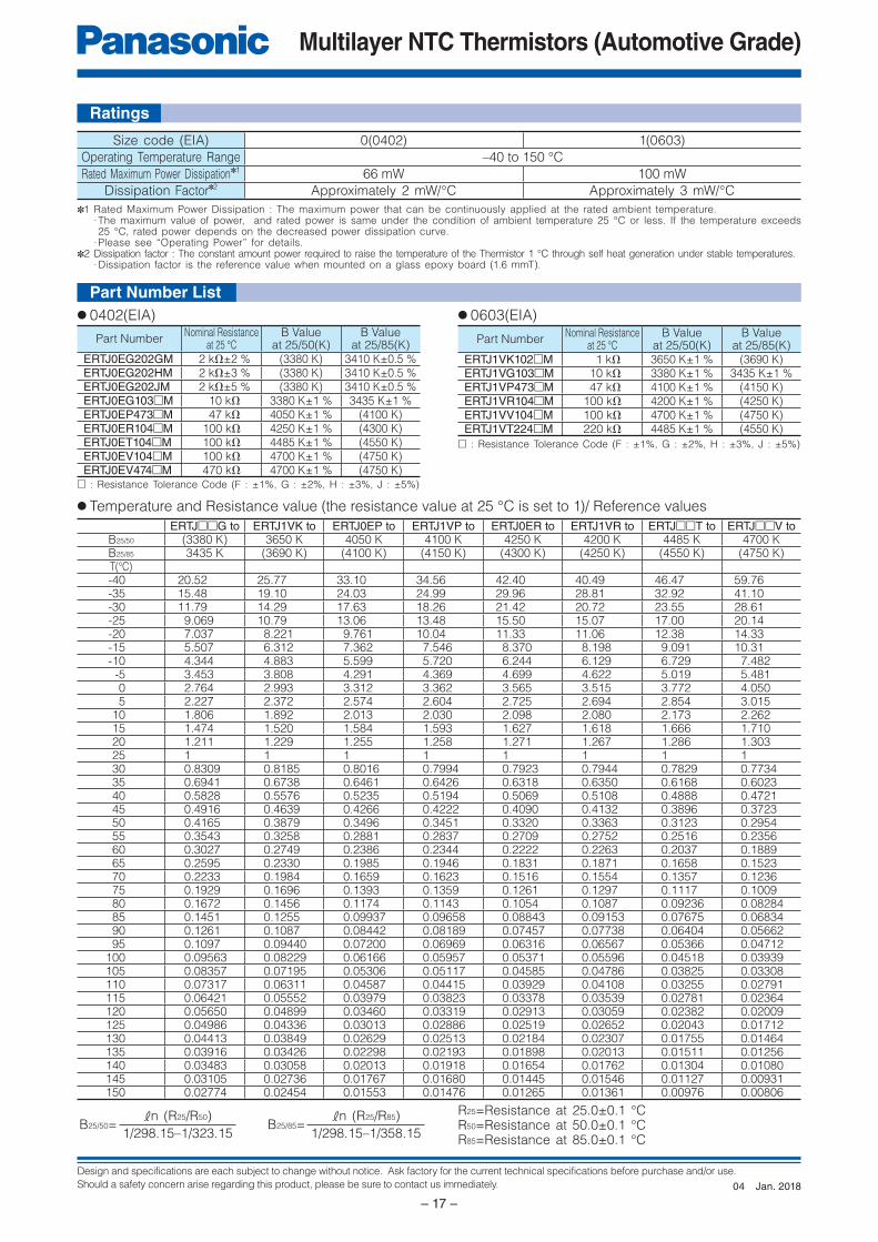
Ratings
● 0402(EIA) ● 0603(EIA)
● Temperature and Resistance value (the resistance value at 25 °C is set to 1)/ Reference values
✽1 Rated Maximum Power Dissipation : The maximum power that can be continuously applied at the rated ambient temperature.· The maximum value of power, and rated power is same under the condition of ambient temperature 25 °C or less. If the temperature exceeds 25 °C, rated power depends on the decreased power dissipation curve.
· Please see “Operating Power” for details.✽2 Dissipation factor : The constant amount power required to raise the temperature of the Thermistor 1 °C through self heat generation under stable temperatures.
· Dissipation factor is the reference value when mounted on a glass epoxy board (1.6 mmT).
□ : Resistance Tolerance Code (F : ±1%, G : ±2%, H : ±3%, J : ±5%)
□ : Resistance Tolerance Code (F : ±1%, G : ±2%, H : ±3%, J : ±5%)
Size code (EIA) 0(0402) 1(0603)
Operating Temperature Range –40 to 150 °C
Rated Maximum Power Dissipation✽1 66 mW 100 mW
Dissipation Factor✽2 Approximately 2 mW/°C Approximately 3 mW/°C
R25=Resistance at 25.0±0.1 °CR50=Resistance at 50.0±0.1 °CR85=Resistance at 85.0±0.1 °C
B25/50=kn (R25/R50)
1/298.15–1/323.15B25/85=
kn (R25/R85)
1/298.15–1/358.15
Part Number List
ERTJ□□G to ERTJ1VK to ERTJ0EP to ERTJ1VP to ERTJ0ER to ERTJ1VR to ERTJ□□T to ERTJ□□V toB25/50 (3380 K) 3650 K 4050 K 4100 K 4250 K 4200 K 4485 K 4700 KB25/85 3435 K (3690 K) (4100 K) (4150 K) (4300 K) (4250 K) (4550 K) (4750 K)T(°C)
-40 20.52 25.77 33.10 34.56 42.40 40.49 46.47 59.76 -35 15.48 19.10 24.03 24.99 29.96 28.81 32.92 41.10 -30 11.79 14.29 17.63 18.26 21.42 20.72 23.55 28.61 -25 9.069 10.79 13.06 13.48 15.50 15.07 17.00 20.14 -20 7.037 8.221 9.761 10.04 11.33 11.06 12.38 14.33 -15 5.507 6.312 7.362 7.546 8.370 8.198 9.091 10.31 -10 4.344 4.883 5.599 5.720 6.244 6.129 6.729 7.482 -5 3.453 3.808 4.291 4.369 4.699 4.622 5.019 5.481 0 2.764 2.993 3.312 3.362 3.565 3.515 3.772 4.050 5 2.227 2.372 2.574 2.604 2.725 2.694 2.854 3.015 10 1.806 1.892 2.013 2.030 2.098 2.080 2.173 2.262 15 1.474 1.520 1.584 1.593 1.627 1.618 1.666 1.710 20 1.211 1.229 1.255 1.258 1.271 1.267 1.286 1.303 25 1 1 1 1 1 1 1 1 30 0.8309 0.8185 0.8016 0.7994 0.7923 0.7944 0.7829 0.7734 35 0.6941 0.6738 0.6461 0.6426 0.6318 0.6350 0.6168 0.6023 40 0.5828 0.5576 0.5235 0.5194 0.5069 0.5108 0.4888 0.4721 45 0.4916 0.4639 0.4266 0.4222 0.4090 0.4132 0.3896 0.3723 50 0.4165 0.3879 0.3496 0.3451 0.3320 0.3363 0.3123 0.2954 55 0.3543 0.3258 0.2881 0.2837 0.2709 0.2752 0.2516 0.2356 60 0.3027 0.2749 0.2386 0.2344 0.2222 0.2263 0.2037 0.1889 65 0.2595 0.2330 0.1985 0.1946 0.1831 0.1871 0.1658 0.1523 70 0.2233 0.1984 0.1659 0.1623 0.1516 0.1554 0.1357 0.1236 75 0.1929 0.1696 0.1393 0.1359 0.1261 0.1297 0.1117 0.1009 80 0.1672 0.1456 0.1174 0.1143 0.1054 0.1087 0.09236 0.08284 85 0.1451 0.1255 0.09937 0.09658 0.08843 0.09153 0.07675 0.06834 90 0.1261 0.1087 0.08442 0.08189 0.07457 0.07738 0.06404 0.05662 95 0.1097 0.09440 0.07200 0.06969 0.06316 0.06567 0.05366 0.04712 100 0.09563 0.08229 0.06166 0.05957 0.05371 0.05596 0.04518 0.03939 105 0.08357 0.07195 0.05306 0.05117 0.04585 0.04786 0.03825 0.03308 110 0.07317 0.06311 0.04587 0.04415 0.03929 0.04108 0.03255 0.02791 115 0.06421 0.05552 0.03979 0.03823 0.03378 0.03539 0.02781 0.02364 120 0.05650 0.04899 0.03460 0.03319 0.02913 0.03059 0.02382 0.02009 125 0.04986 0.04336 0.03013 0.02886 0.02519 0.02652 0.02043 0.01712 130 0.04413 0.03849 0.02629 0.02513 0.02184 0.02307 0.01755 0.01464 135 0.03916 0.03426 0.02298 0.02193 0.01898 0.02013 0.01511 0.01256 140 0.03483 0.03058 0.02013 0.01918 0.01654 0.01762 0.01304 0.01080 145 0.03105 0.02736 0.01767 0.01680 0.01445 0.01546 0.01127 0.00931 150 0.02774 0.02454 0.01553 0.01476 0.01265 0.01361 0.00976 0.00806
Part NumberNominal Resistance
at 25 °CB Value
at 25/50(K)B Value
at 25/85(K)ERTJ0EG202GM 2 kΩ±2 % (3380 K) 3410 K±0.5 %ERTJ0EG202HM 2 kΩ±3 % (3380 K) 3410 K±0.5 %ERTJ0EG202JM 2 kΩ±5 % (3380 K) 3410 K±0.5 %ERTJ0EG103□M 10 kΩ 3380 K±1 % 3435 K±1 %ERTJ0EP473□M 47 kΩ 4050 K±1 % (4100 K)ERTJ0ER104□M 100 kΩ 4250 K±1 % (4300 K)ERTJ0ET104□M 100 kΩ 4485 K±1 % (4550 K)ERTJ0EV104□M 100 kΩ 4700 K±1 % (4750 K)ERTJ0EV474□M 470 kΩ 4700 K±1 % (4750 K)
Part NumberNominal Resistance
at 25 °CB Value
at 25/50(K)B Value
at 25/85(K)ERTJ1VK102□M 1 kΩ 3650 K±1 % (3690 K)ERTJ1VG103□M 10 kΩ 3380 K±1 % 3435 K±1 %ERTJ1VP473□M 47 kΩ 4100 K±1 % (4150 K)ERTJ1VR104□M 100 kΩ 4200 K±1 % (4250 K)ERTJ1VV104□M 100 kΩ 4700 K±1 % (4750 K)ERTJ1VT224□M 220 kΩ 4485 K±1 % (4550 K)
Jan. 201804
Design and specifications are each subject to change without notice. Ask factory for the current technical specifications before purchase and/or use.
Should a safety concern arise regarding this product, please be sure to contact us immediately.
Multilayer NTC Thermistors (Automotive Grade)
– 18 –
1.0
Test Sample
0.5R 0.5
Board
1.0
TestSample Unit : mm
20
45±2 45±2
Bend
ing
dis
tance
Unit : mm
R340
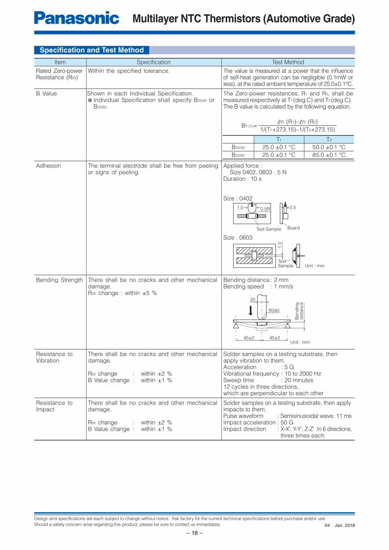
Item Specifi cation Test Method
Rated Zero-power Resistance (R25)
Within the specifi ed tolerance. The value is measured at a power that the infl uence of self-heat generation can be negligible (0.1mW or less), at the rated ambient temperature of 25.0±0.1°C.
B Value Shown in each Individual Specifi cation.✽ Individual Specifi cation shall specify B25/50 or
B25/85.
The Zero-power resistances; R1 and R2, shall be measured respectively at T1 (deg.C) and T2 (deg.C).The B value is calculated by the following equation.
BT1/T2=kn (R1)–kn (R2)
1/(T1+273.15)–1/(T2+273.15)
T1 T2
B25/50 25.0 ±0.1 °C 50.0 ±0.1 °C
B25/85 25.0 ±0.1 °C 85.0 ±0.1 °C
Adhesion The terminal electrode shall be free from peeling or signs of peeling.
Applied force : Size 0402, 0603 : 5 N
Duration : 10 s
Size : 0402
Size : 0603
Bending Strength There shall be no cracks and other mechanical damage.R25 change : within ±5 %
Bending distance : 2 mmBending speed : 1 mm/s
Resistance to Vibration
There shall be no cracks and other mechanical damage.
R25 change : within ±2 %B Value change : within ±1 %
Solder samples on a testing substrate, thenapply vibration to them.Acceleration : 5 GVibrational frequency : 10 to 2000 HzSweep time : 20 minutes12 cycles in three directions, which are perpendicular to each other
Resistance to Impact
There shall be no cracks and other mechanical damage.
R25 change : within ±2 %B Value change : within ±1 %
Solder samples on a testing substrate, then apply impacts to them.Pulse waveform : Semisinusoidal wave, 11 msImpact acceleration : 50 GImpact direction : X-X', Y-Y', Z-Z' In 6 directions, three times each
Specifi cation and Test Method
Jan. 201804
Design and specifications are each subject to change without notice. Ask factory for the current technical specifications before purchase and/or use.
Should a safety concern arise regarding this product, please be sure to contact us immediately.
Multilayer NTC Thermistors (Automotive Grade)
– 19 –
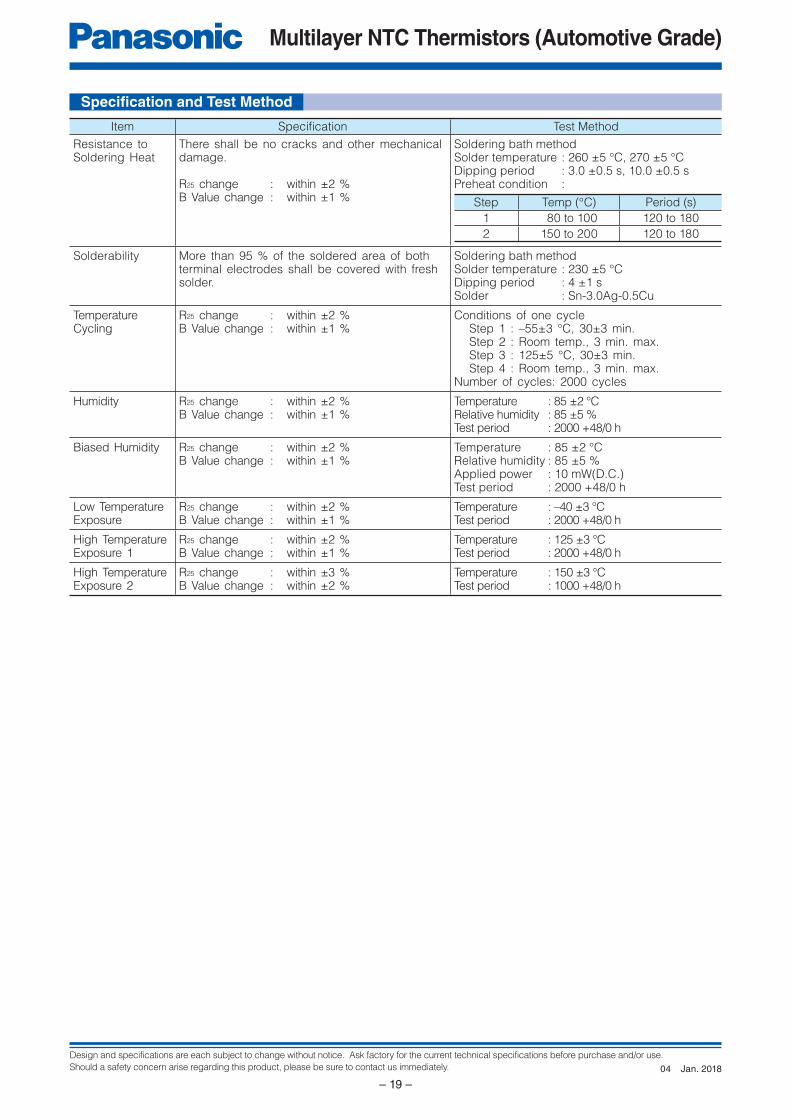
Item Specifi cation Test Method
Resistance to Soldering Heat
There shall be no cracks and other mechanical damage.
R25 change : within ±2 %B Value change : within ±1 %
Soldering bath methodSolder temperature : 260 ±5 °C, 270 ±5 °CDipping period : 3.0 ±0.5 s, 10.0 ±0.5 sPreheat condition :
Step Temp (°C) Period (s)
1 80 to 100 120 to 180
2 150 to 200 120 to 180
Solderability More than 95 % of the soldered area of both terminal electrodes shall be covered with fresh solder.
Soldering bath methodSolder temperature : 230 ±5 °CDipping period : 4 ±1 sSolder : Sn-3.0Ag-0.5Cu
Temperature Cycling
R25 change : within ±2 %B Value change : within ±1 %
Conditions of one cycleStep 1 : –55±3 °C, 30±3 min.Step 2 : Room temp., 3 min. max.Step 3 : 125±5 °C, 30±3 min.Step 4 : Room temp., 3 min. max.
Number of cycles: 2000 cycles
Humidity R25 change : within ±2 %B Value change : within ±1 %
Temperature : 85 ±2 °CRelative humidity : 85 ±5 %Test period : 2000 +48/0 h
Biased Humidity R25 change : within ±2 %B Value change : within ±1 %
Temperature : 85 ±2 °CRelative humidity : 85 ±5 %Applied power : 10 mW(D.C.)Test period : 2000 +48/0 h
Low TemperatureExposure
R25 change : within ±2 %B Value change : within ±1 %
Temperature : –40 ±3 °CTest period : 2000 +48/0 h
High TemperatureExposure 1
R25 change : within ±2 %B Value change : within ±1 %
Temperature : 125 ±3 °CTest period : 2000 +48/0 h
High TemperatureExposure 2
R25 change : within ±3 %B Value change : within ±2 %
Temperature : 150 ±3 °CTest period : 1000 +48/0 h
Specifi cation and Test Method
Jan. 201804
Design and specifications are each subject to change without notice. Ask factory for the current technical specifications before purchase and/or use.
Should a safety concern arise regarding this product, please be sure to contact us immediately.
Multilayer NTC Thermistors (Automotive Grade)
– 20 –
L
T
W
L1 L2
E
C
D
A
W2
W1
B
100 min.
Vacant position
Top cover tape
400 min.
160 min.
Vacant positiont2 Chip component
Feeding hole Chip pocket
fD0
P1 P2 P0 Tape running direction
EF W
B
A
t1
t1
P1 P2 P0 Tape running directiont2
Chip component
Feeding hole Chip pocket
fD0
A
B
F WE
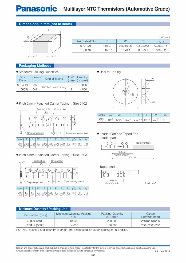
Size Code (EIA) L W T L1, L2
0 (0402) 1.0±0.1 0.50±0.05 0.50±0.05 0.25±0.15
1 (0603) 1.60±0.15 0.8±0.1 0.8±0.1 0.3±0.2
Taped end
(Unit : mm)
● Pitch 2 mm (Punched Carrier Taping) : Size 0402
● Pitch 4 mm (Punched Carrier Taping) : Size 0603
Symbol A B W F E P1 P2 P0 fD0 t1 t2
Dim.(mm)
1.0±0.1
1.8±0.1
8.0±0.2
3.50±0.05
1.75±0.10
4.0±0.1
2.00±0.05
4.0±0.1
1.5+0.10
1.1max.
1.4max.
Symbol A B W F E P1 P2 P0 fD0 t1 t2
Dim.(mm)
0.62±0.05
1.12±0.05
8.0±0.2
3.50±0.05
1.75±0.10
2.00±0.05
2.00±0.05
4.0±0.1
1.5+0.10
0.7max.
1.0max.
(Unit : mm)
Symbol fA fB C D E W1 W2
Dim.(mm)
180–3 60.0+1.0
13.0±0.5 21.0±0.8 2.0±0.5 9.0+1.0
11.4±1.00
0 0
SizeCode
Thickness(mm)
Kind of TapingPitch
(mm)Quantity(pcs./reel)
0 (0402) 0.5Punched Carrier Taping
2 10,000
1 (0603) 0.8 4 4,000
Dimensions in mm (not to scale)
Packaging Methods
Minimum Quantity / Packing Unit
● Standard Packing Quantities ● Reel for Taping
● Leader Part and Taped End
Leader part
Part Number (Size)Minimum Quantity/ Packing
UnitPacking Quantity
in CartonCarton
L×W×H (mm)
ERTJ0 (0402) 10,000 200,000 250×200×200
ERTJ1 (0603) 4,000 80,000 250×200×200
Part No., quantity and country of origin are designated on outer packages in English.
Jan. 201804
Design and specifications are each subject to change without notice. Ask factory for the current technical specifications before purchase and/or use.
Should a safety concern arise regarding this product, please be sure to contact us immediately.
Multilayer NTC Thermistors (Automotive Grade)
– 21 –
0 25 50−25
120
100
80
60
75 100 125
Ambient temperature (°C)
Max
imum
pow
er d
issi
patio
n/
Rat
ed m
axim
um p
ower
dis
sipa
tion
(%)
150 175
40
20
0
Multilayer NTC Thermistors (Automotive Grade)Series: ERTJ-M
Handling Precautions
1. Circuit Design1.1 Operating Temperature and Storage Temperature
When operating a components-mounted circuit,
please be sure to observe the “Operating Temperature
Range”, written in delivery specifications. Please
remember not to use the product under the condition
that exceeds the specified maximum temperature.
Storage temperature of PCB after mounting
Thermistors, which is not operated, should be within
the specified “Storage Temperature Range” in the
delivery specifications.
1.2 Operating PowerThe electricity applied to between terminals of
Thermistors should be under the specified maximum
power dissipation.
There are possibilities of breakage and burn-out due
to excessive self-heating of Thermistors, if the power
exceeds maximum power dissipation when operating.
Please consider installing protection circuit for your
circuit to improve the safety, in case of abnormal
voltage application and so on.
Thermistors’ performance of temperature detection
would be deteriorated if self-heating occurs,
even when you use it under the maximum power
dissipation.
Please consider the maximum power dissipation and
dissipation factor.
Safety PrecautionsThe Multilayer NTC Thermistors (Automotive Grade), hereafter referred to as Thermistors, is designed for use in automotive devices. When subjected to severe electrical, environmental, and/or mechanical stress beyond the specifications, as noted in the Ratings and Specified Conditions section, the Thermistors’ performance may be degraded, or become failure mode, such as short circuit mode and open-circuit mode. If you use under the condition of short-circuit, heat generation of thermistors will occur by running large current due to application of voltage. There are possibilities of smoke emission, substrate burn-out, and, in the worst case, fire.For products which require higher safety levels, please carefully consider how a single malfunction can affect your product. In order to ensure the safety in the case of a single malfunction, please design products with fail-safe, such as setting up protecting circuits, etc.
● For the following applications and conditions, please contact us for product of special specification not found in this document.· When your application may have difficulty complying with the safety or handling precautions specified below.· High-quality and high-reliability required devices that have possibility of causing hazardous conditions, such as
death or injury (regardless of directly or indirectly), due to failure or malfunction of the product.
1 Aircraft and Aerospace Equipment (artificial satellite, rocket, etc.)2 Submarine Equipment (submarine repeating equipment, etc.)3 Transportation Equipment (airplanes, trains, ship, traffic signal controllers, etc.)4 Power Generation Control Equipment (atomic power, hydroelectric power, thermal power plant control system, etc.)5 Medical Equipment (life-support equipment, pacemakers, dialysis controllers, etc.)6 Information Processing Equipment (large scale computer systems, etc.)7 Electric Heating Appliances, Combustion devices (gas fan heaters, oil fan heaters, etc.)8 Rotary Motion Equipment9 Security SystemsJ And any similar types of equipment
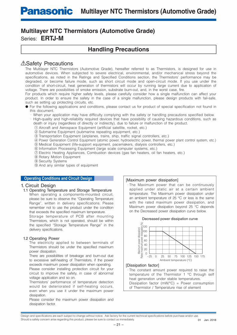
[Maximum power dissipation] · The Maximum power that can be continuously
applied under static air at a certain ambient
temperature. The Maximum power dissipation under
an ambient temperature of 25 °C or less is the same
with the rated maximum power dissipation, and
Maximum power dissipation beyond 25 °C depends
on the Decreased power dissipation curve below.
[Dissipation factor] · The constant amount power required to raise the
temperature of the Thermistor 1 °C through self
heat generation under stable temperatures.
Dissipation factor (mW/°C) = Power consumption
of Thermistor / Temperature rise of element
Decreased power dissipation curve
Operating Conditions and Circuit Design
Jan. 201801
Design and specifications are each subject to change without notice. Ask factory for the current technical specifications before purchase and/or use.
Should a safety concern arise regarding this product, please be sure to contact us immediately.
Multilayer NTC Thermistors (Automotive Grade)
– 22 –
ab
c
LandSMD
Solder resist
(a) Excessive amount (b) Proper amount (c) Insufficient amount
Solder resistLand
Portion to beexcessively soldered
A lead wire ofRetro-fittedcomponent
Solderingiron
Solder(Ground solder)
Chassis
Electrode pattern
Solder resist
Solder resist
Solder resistThe lead wire of a component with lead wires
1.3 Environmental RestrictionsThe Thermistors shall not be operated and/or
stored under the following conditions.
(1) Environmental conditions
(a) Under direct exposure to water or salt water
(b) Under conditions where water can condense
and/or dew can form
(c) Under conditions containing corrosive gases
such as hydrogen sulfide, sulfurous acid,
chlorine and ammonia
(2) Mechanical conditions
The place where vibration or impact that
exceeds specified conditions written in delivery
specification is loaded.
1.4 Measurement of ResistanceThe resistance of the Thermistors varies depending
on ambient temperatures and self-heating. To
measure the resistance value when examining circuit
configuration and conducting receiving inspection
and so on, the following points should be taken into
consideration:
1 Measurement temp : 25±0.1 °CMeasurement in l iquid (si l icon oil, etc.) is
recommended for a stable measurement temperature.
2 Power : 0.10 mW max.4 terminal measurement with a constant-current
power supply is recommended.
2. Design of Printed Circuit Board2.1 Selection of Printed Circuit Boards
There is a possibility of performance deterioration
by heat shock (temperature cycles), which causes
cracks, from alumina substrate.
Please confirm that the substrate you use does
not deteriorate the Thermistors’ quality.
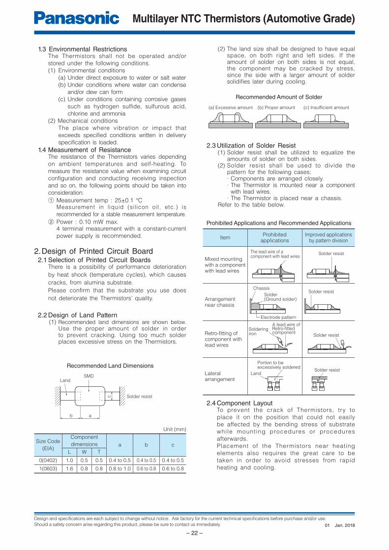
2.2 Design of Land Pattern(1) Recommended land dimensions are shown below.
Use the proper amount of solder in order to prevent cracking. Using too much solder places excessive stress on the Thermistors.
Unit (mm)
Size Code
(EIA)
Component
dimensions a b c
L W T
0(0402) 1.0 0.5 0.5 0.4 to 0.5 0.4 to 0.5 0.4 to 0.5
1(0603) 1.6 0.8 0.8 0.8 to 1.0 0.6 to 0.8 0.6 to 0.8
Recommended Land Dimensions
(2) The land size shall be designed to have equal space, on both right and left sides. If the amount of solder on both sides is not equal, the component may be cracked by stress, since the side with a larger amount of solder solidifies later during cooling.
Recommended Amount of Solder
2.3 Utilization of Solder Resist(1) Solder resist shall be utilized to equalize the
amounts of solder on both sides.(2) Solder resist shall be used to divide the
pattern for the following cases;· Components are arranged closely.· The Thermistor is mounted near a component
with lead wires.· The Thermistor is placed near a chassis.
Refer to the table below.
Prohibited Applications and Recommended Applications
ItemProhibited
applicationsImproved applications
by pattern division
Mixed mounting with a component with lead wires
Arrangement near chassis
Retro-fi tting of component with lead wires
Lateral arrangement
2.4 Component LayoutTo prevent the crack of Thermistors, try to
place it on the position that could not easily
be affected by the bending stress of substrate
whi le mounting procedures or procedures
afterwards.
Placement of the Thermistors near heating
elements also requires the great care to be
taken in order to avoid stresses from rapid
heating and cooling.
Jan. 201801
Design and specifications are each subject to change without notice. Ask factory for the current technical specifications before purchase and/or use.
Should a safety concern arise regarding this product, please be sure to contact us immediately.
Multilayer NTC Thermistors (Automotive Grade)
– 23 –
AB
C
E
D
Slit
Magnitude of stress A>B=C>D>E
Perforation
Supportingpin
SupportingpinCrackSeparation of Solder
Crack
(1) To minimize mechanical stress caused by the warp or bending of a PC board, please follow the recommended Thermistors’ layout below.
(2) The following layout is for your reference since mechanical stress near the dividing/breaking position of a PC board varies depending on the mounting position of the Thermistors.
(3) The magnitude of mechanical stress applied to the Thermistors when dividing the circuit board in descending order is as follows:
push back < slit < V-groove < perforation. Also take into account the layout of the
Thermistors and the dividing/breaking method.(4) When the Thermistors are placed near heating
elements such as heater, etc., cracks from thermal stresses may occur under following situation:· Soldering the Thermistors directly to heating
elements.· Sharing the land with heating elements.
If planning to conduct above-mentioned mounting
and/or placement, please contact us in advance.
2.5 Mounting Density and SpacesIntervals between components should not be too
narrow to prevent the influence from solder bridges
and solder balls. The space between components
should be carefully determined.
1. Storage(1) The Thermistors shall be stored between 5 to
40 °C and 20 to 70 % RH, not under severe conditions of high temperature and humidity.
(2) If stored in a place where humidity, dust, or corrosive gasses (hydrogen sulfide, sulfurous acid, hydrogen chloride and ammonia, etc.) are contained, the solderability of terminal electrodes will be deteriorated.
In addition, storage in a places where the heat or direct sunlight exposure occur will cause mounting problems due to deformation of tapes and reels and components and taping/reels sticking together.
(3) Do not store components longer than 6 months. Check the solderability of products that have been stored for more than 6 months before use
2. Chip Mounting Consideration(1) When mounting the Thermistors/components
on a PC board, the Thermistor bodies shall be free from excessive impact loads such as mechanical impact or stress due to the positioning, pushing force and displacement of vacuum nozzles during mounting.
(2) Maintenance and inspection of the Chip Mounter must be performed regularly.
(3) If the bottom dead center of the vacuum nozzle is too low, the Thermistor will crack from excessive force during mounting.
The following precautions and recommendations
are for your reference in use.
(a) Set and adjust the bottom dead center of the
vacuum nozzles to the upper surface of the PC
board after correcting the warp of the PC board.
(b) Set the pushing force of the vacuum nozzle
during mounting to 1 to 3 N in static load.
(c) For double surface mounting, apply a
supporting pin on the rear surface of the PC
board to suppress the bending of the PC
board in order to minimize the impact of the
vacuum nozzles. Typical examples are shown
in the table below.
Item Prohibited mounting Recommended mounting
Single surface mouting
The supporting pin does not necessarily have to be positioned beneath the Thermistor.
Double surface mounting
(d) Adjust the vacuum nozzles so that their bottom
dead center during mounting is not too low.
(4) The closing dimensions of the positioning chucks shall be controlled. Maintenance and replacement of positioning chucks shall be performed regularly to prevent chipping or cracking of the Thermistors caused by mechanical impact during positioning due to worn positioning chucks.
(5) Maximum stroke of the nozzle shall be adjusted so that the maximum bending of PC board does not exceed 0.5 mm at 90 mm span. The PC board shall be supported by an adequate number of supporting pins.
3. Selection of Soldering FluxSoldering flux may seriously affect the performance
of the Thermistors. The following shall be confirmed
before use.
(1) The soldering flux should have a halogen based content of 0.1 wt% (converted to chlorine) or below.
Do not use soldering flux with strong acid.(2) When applying water-soluble soldering flux,
wash the Thermistors sufficiently because the soldering flux residue on the surface of PC boards may deteriorate the insulation resistance on the Thermistors’ surface.
Prohibited layout Recommended layout
Layout the Thermistors sideways against the stressing direction
Precautions for Assembly
Jan. 201801
Design and specifications are each subject to change without notice. Ask factory for the current technical specifications before purchase and/or use.
Should a safety concern arise regarding this product, please be sure to contact us immediately.
Multilayer NTC Thermistors (Automotive Grade)
– 24 –
Time
Gradualcooling
5
Heating3
Peak4
Temp. rise
△T 2
Preheating1
60 sec max.60 to 120 sec
Tem
pera
ture
(°C
)
260
220
180
140
△T
Preheating
Gradual cooling
60 to 120 sec 3 sec max.
4. Soldering4.1 Reflow Soldering
The reflow soldering temperature conditions are
composed of temperature curves of Preheating,
Temp. rise, Heating, Peak and Gradual cooling.
Large temperature difference inside the Thermistors
caused by rapid heat application to the Thermistors
may lead to excessive thermal stresses, contributing
to the thermal cracks. The Preheating temperature
requires controlling with great care so that tombstone
phenomenon may be prevented.
Item Temperature Period or Speed
1Preheating 140 to 180 °C 60 to 120 sec
2Temp. risePreheating temp
to Peak temp.2 to 5 °C /sec
3Heating 220 °C min. 60 sec max.
4Peak 260 °C max. 10 sec max.
5Gradual coolingPeak temp.
to 140 °C1 to 4 °C /sec
Recommended profi le of Refl ow soldering (EX)
△T : Allowable temperature difference △T < 150 °C
The rapid cooling (forced cooling) during Gradual
cooling part should be avoided, because this may
cause defects such as the thermal cracks, etc.
When the Thermistors are immersed into a cleaning
solvent, make sure that the surface temperatures of
the devices do not exceed 100 °C.
Per fo rming re f low so lder ing tw ice under
the condit ions shown in the f igure above
[Recommended profile of Reflow soldering (EX)] will
not cause any problems. However, pay attention to
the possible warp and bending of the PC board.
4.2 Hand SolderingHand soldering typically causes significant temperature
change, which may induce excessive thermal stresses
inside the Thermitors, resulting in the thermal cracks, etc.
In order to prevent any defects, the following should
be observed.
· The temperature of the soldering tips should be
controlled with special care.
· The direct contact of soldering tips with the
Thermistors and/or terminal electrodes should be
avoided.
· Dismounted Thermistors shall not be reused.
(1) Condition 1 (with preheating)(a) Soldering:
Use thread solder (f1 mm or below) which
contains flux with low chlorine, developed
for precision electronic equipment.
(b) Preheating:
Conduct sufficient pre-heating, and make
sure that the temperature difference
between solder and Thermistors’ surface
is 150 °C or less.
(c) Temperature of Iron tip: 300 °C max.
(The required amount of solder shall be
melted in advance on the soldering tip.)
(d) Gradual cooling:
After soldering, the Thermistors shall be
cooled gradually at room temperature.
Recommended profi le of Hand soldering (EX)
△T : Allowable temperature difference △T < 150 °C
(2) Condition 2 (without preheating)Hand soldering can be performed without
preheating, by following the conditions below:
(a) Soldering iron tip shall never directly
touch the ceramic and terminal electrodes
of the Thermistors.
(b) The lands are sufficiently preheated with a
soldering iron tip before sliding the soldering
iron tip to the terminal electrodes of the
Thermistors for soldering.
Conditions of Hand soldering without preheating
Item Condition
Temperature of Iron tip 270 °C max.
Wattage 20 W max.
Shape of Iron tip f3 mm max.
Soldering time witha soldering iron
3 sec max.
5. Post Soldering Cleaning5.1 Cleaning solvent
Soldering flux residue may remain on the PC
board if cleaned with an inappropriate solvent.
This may deteriorate the electrical characteristics
and reliability of the Thermistors.
5.2 Cleaning conditionsInappropriate cleaning conditions such as insufficient
cleaning or excessive cleaning may impair the electrical
characteristics and reliability of the Thermistors.
(1) Insufficient cleaning can lead to:
(a) The halogen substance found in the residue
of the soldering flux may cause the metal of
terminal electrodes to corrode.
(b) The halogen substance found in the residue
of the soldering flux on the surface of the
Thermistors may change resistance values.
(c) Water-soluble soldering flux may have more
remarkable tendencies of (a) and (b) above
compared to those of rosin soldering flux.
Jan. 201801
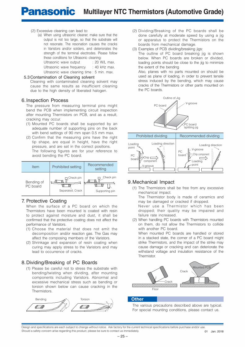
Design and specifications are each subject to change without notice. Ask factory for the current technical specifications before purchase and/or use.
Should a safety concern arise regarding this product, please be sure to contact us immediately.
Multilayer NTC Thermistors (Automotive Grade)
– 25 –
Supporting pinSeparated, Crack
Check pinCheck pin
Bending Torsion
PC board splitting jig
V-groovePC board
Outline of Jig
PCboard
Chipcomponent
Loadingpoint
V-groove
Loading direction
PCboard Chip component
Loadingpoint
V-groove
Loading direction
Floor
Crack
Mounted PCB
Crack
(2) Excessive cleaning can lead to:(a) When using ultrasonic cleaner, make sure that the
output is not too large, so that the substrate will
not resonate. The resonation causes the cracks
in Varistors and/or solders, and deteriorates the
strength of the terminal electrodes. Please follow
these conditions for Ultrasonic cleaning:
Ultrasonic wave output : 20 W/L max.
Ultrasonic wave frequency : 40 kHz max.
Ultrasonic wave cleaning time : 5 min. max.
5.3 Contamination of Cleaning solventCleaning with contaminated cleaning solvent may
cause the same results as insufficient cleaning
due to the high density of liberated halogen.
6. Inspection ProcessThe pressure from measuring terminal pins might
bend the PCB when implementing circuit inspection
after mounting Thermistors on PCB, and as a result,
cracking may occur.
(1) Mounted PC boards shall be supported by an
adequate number of supporting pins on the back
with bend settings of 90 mm span 0.5 mm max.
(2) Confi rm that the measuring pins have the right
tip shape, are equal in height, have the right
pressure, and are set in the correct positions.
The following figures are for your reference to
avoid bending the PC board.
Item Prohibited settingRecommended
setting
Bending ofPC board
7. Protective CoatingWhen the surface of a PC board on which the
Thermistors have been mounted is coated with resin
to protect against moisture and dust, it shall be
confirmed that the protective coating does not affect the
performance of Varistors.
(1) Choose the material that does not emit the
decomposition and/or reaction gas. The Gas may
affect the composing members of the Varistors.
(2) Shrinkage and expansion of resin coating when
curing may apply stress to the Varistors and may
lead to occurrence of cracks.
8. Dividing/Breaking of PC Boards(1) Please be careful not to stress the substrate with
bending/twisting when dividing, after mounting
components including Varistors. Abnormal and
excessive mechanical stress such as bending or
torsion shown below can cause cracking in the
Thermistors.
(2) Dividing/Breaking of the PC boards shall be
done carefully at moderate speed by using a jig
or apparatus to protect the Thermistors on the
boards from mechanical damage.
(3) Examples of PCB dividing/breaking jigs:
The outline of PC board breaking jig is shown
below. When PC boards are broken or divided,
loading points should be close to the jig to minimize
the extent of the bending
Also, planes with no parts mounted on should be
used as plane of loading, in order to prevent tensile
stress induced by the bending, which may cause
cracks of the Thermistors or other parts mounted on
the PC boards.
Prohibited dividing Recommended dividing
9. Mechanical Impact(1) The Thermistors shall be free from any excessive
mechanical impact.
The Thermistor body is made of ceramics and
may be damaged or cracked if dropped.
Never use a Thermistor which has been
dropped; their quality may be impaired and
failure rate increased.
(2) When handling PC boards with Thermistors mounted
on them, do not allow the Thermistors to collide
with another PC board.
When mounted PC boards are handled or stored
in a stacked state, the corner of a PC board might
strike Thermistors, and the impact of the strike may
cause damage or cracking and can deteriorate the
withstand voltage and insulation resistance of the
Thermistor.
The various precautions described above are typical.
For special mounting conditions, please contact us.
Other
Jan. 201801
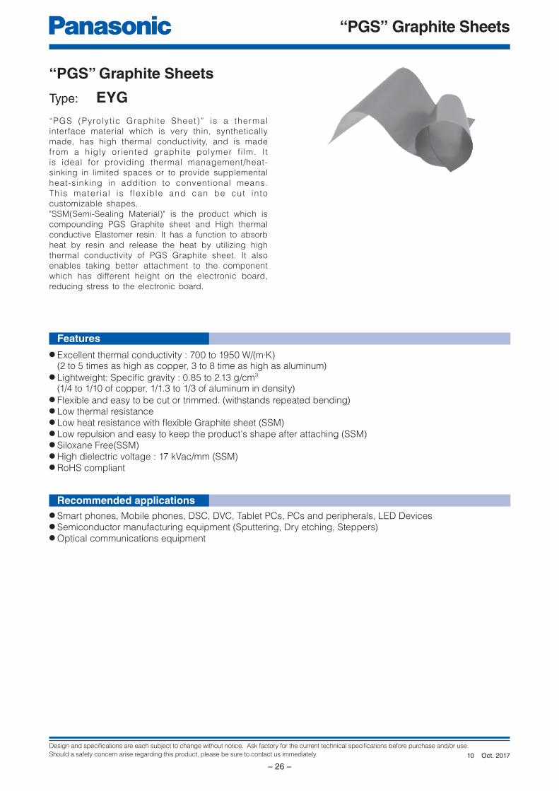
Design and specifications are each subject to change without notice. Ask factory for the current technical specifications before purchase and/or use.
Should a safety concern arise regarding this product, please be sure to contact us immediately.
“PGS” Graphite Sheets
– 26 –
Features
Recommended applications
● Excellent thermal conductivity : 700 to 1950 W/(m·K) (2 to 5 times as high as copper, 3 to 8 time as high as aluminum)● Lightweight: Specifi c gravity : 0.85 to 2.13 g/cm3
(1/4 to 1/10 of copper, 1/1.3 to 1/3 of aluminum in density)● Flexible and easy to be cut or trimmed. (withstands repeated bending)● Low thermal resistance● Low heat resistance with fl exible Graphite sheet (SSM) ● Low repulsion and easy to keep the product's shape after attaching (SSM) ● Siloxane Free(SSM)● High dielectric voltage : 17 kVac/mm (SSM) ● RoHS compliant
● Smart phones, Mobile phones, DSC, DVC, Tablet PCs, PCs and peripherals, LED Devices● Semiconductor manufacturing equipment (Sputtering, Dry etching, Steppers)● Optical communications equipment
“PGS” Graphite Sheets
Type: EYG“PGS (Pyrolyt ic Graphite Sheet)” is a thermal
interface material which is very thin, synthetically
made, has high thermal conductivity, and is made
from a higly oriented graphite polymer f i lm. It
is ideal for providing thermal management/heat-
sinking in limited spaces or to provide supplemental
heat-sinking in addition to conventional means.
This mater ia l is f lex ible and can be cut into
customizable shapes.
"SSM(Semi-Sealing Material)" is the product which is
compounding PGS Graphite sheet and High thermal
conductive Elastomer resin. It has a function to absorb
heat by resin and release the heat by utilizing high
thermal conductivity of PGS Graphite sheet. It also
enables taking better attachment to the component
which has different height on the electronic board,
reducing stress to the electronic board.
Oct. 201710
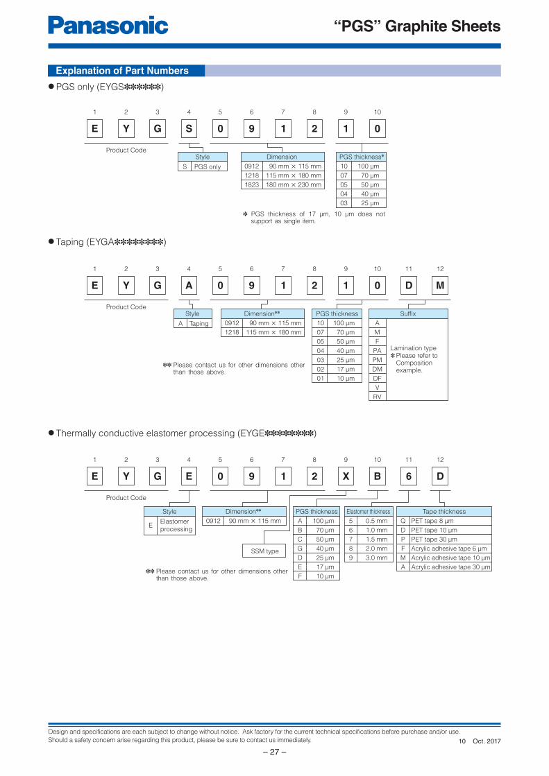
Design and specifications are each subject to change without notice. Ask factory for the current technical specifications before purchase and/or use.
Should a safety concern arise regarding this product, please be sure to contact us immediately.
“PGS” Graphite Sheets
– 27 –
E
1
Y
2
G
3 4 5 6 7 8 9 10
S 0 9 1 2 1 0
Style
S PGS only 100 μm
70 μm
50 μm
40 μm
25 μm
PGS thickness✽
10
07
05
04
03
90 mm × 115 mm
115 mm × 180 mm
180 mm × 230 mm
Dimension
0912
1218
1823
Product Code
E
1
Y
2
G
3 4 5 6 7 8 9 10
A 0 9 1 2 1 0 D M
Style
A Taping 100 μm
70 μm
50 μm
40 μm
25 μm
17 μm
10 μm
PGS thickness
10
07
05
04
03
02
01
90 mm × 115 mm
115 mm × 180 mm
Dimension✽✽
0912
1218
11 12
Suffix
Lamination type✽ Please refer to Composition example.
A
M
F
PA
PM
DM
DF
V
RV
Product Code
E
1
Y
2
G
3 4 5 6 7 8 9 10
E 0 9 1 2 X B 6 D
Style
EElastomer
processing
100 μm
70 μm
50 μm
40 μm
25 μm
17 μm
10 μm
PGS thickness
SSM type
A
B
C
G
D
E
F
90 mm × 115 mm
Dimension✽✽
0912
11 12
0.5 mm
1.0 mm
1.5 mm
2.0 mm
3.0 mm
Elastomer thickness
5
6
7
8
9
PET tape 8 μm
PET tape 10 μm
PET tape 30 μm
Acrylic adhesive tape 6 μm
Acrylic adhesive tape 10 μm
Acrylic adhesive tape 30 μm
Tape thickness
Q
D
P
F
M
A
Product Code
● PGS only (EYGS✽✽✽✽✽✽)
● Taping (EYGA✽✽✽✽✽✽✽✽)
● Thermally conductive elastomer processing (EYGE✽✽✽✽✽✽✽✽)
Explanation of Part Numbers
✽ PGS thickness of 17 μm, 10 μm does not support as single item.
✽✽ Please contact us for other dimensions other than those above.
✽✽ Please contact us for other dimensions other than those above.
Oct. 201710
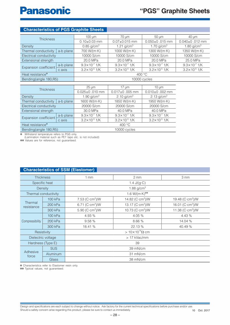
Design and specifications are each subject to change without notice. Ask factory for the current technical specifications before purchase and/or use.
Should a safety concern arise regarding this product, please be sure to contact us immediately.
“PGS” Graphite Sheets
– 28 –
Characteristics of PGS Graphite Sheets
Thickness100 μm 70 μm 50 μm 40 μm
0.10±0.03 mm 0.07±0.015 mm 0.050±0 .015 mm 0.040±0 .012 mm
Density 0.85 g/cm3 1.21 g/cm3 1.70 g/cm3 1.80 g/cm3
Thermal conductivity a-b plane 700 W/(m·K) 1000 W/(m·K) 1300 W/(m·K) 1350 W/(m·K)
Electrical conductivity 10000 S/cm 10000 S/cm 10000 S/cm 10000 S/cm
Extensional strength 20.0 MPa 20.0 MPa 20.0 MPa 25.0 MPa
Expansion coeffi cienta-b plane 9.3×10⁻⁷ 1/K 9.3×10⁻⁷ 1/K 9.3×10⁻⁷ 1/K 9.3×10⁻⁷ 1/K
c axis 3.2×10⁻⁵ 1/K 3.2×10⁻⁵ 1/K 3.2×10⁻⁵ 1/K 3.2×10⁻⁵ 1/K
Heat resistance✽ 400 °C
Bending(angle 180,R5) 10000 cycles
✽ Withstand temperature refers to PGS only. (Lamination material such as PET tape etc. is not included)✽✽ Values are for reference, not guaranteed.
Thickness25 μm 17 μm 10 μm
0.025±0 .010 mm 0.017±0 .005 mm 0.010±0 .002 mm
Density 1.90 g/cm3 2.10 g/cm3 2.13 g/cm3
Thermal conductivity a-b plane 1600 W/(m·K) 1850 W/(m·K) 1950 W/(m·K)
Electrical conductivity 20000 S/cm 20000 S/cm 20000 S/cm
Extensional strength 30.0 MPa 40.0 MPa 40.0 MPa
Expansion coeffi cienta-b plane 9.3×10⁻⁷ 1/K 9.3×10⁻⁷ 1/K 9.3×10⁻⁷ 1/K
c axis 3.2×10⁻⁵ 1/K 3.2×10⁻⁵ 1/K 3.2×10⁻⁵ 1/K
Heat resistance✽ 400 °C
Bending(angle 180,R5) 10000 cycles
Characteristics of SSM (Elastomer)
✽ Characteristics refer to Elastomer resin only.✽✽ Typical values, not guaranteed.
Thickness 1 mm 2 mm 3 mm
Specifi c heat 1.4 J/(g∙C)
Density 1.88 g/cm3
Thermal conductivity 1.6 W/(m·K)✽✽
Thermal
resistance
100 kPa 7.53 (C·cm2)/W 14.82 (C·cm2)/W 19.48 (C·cm2)/W
200 kPa 6.71 (C·cm2)/W 13.17 (C·cm2)/W 16.01 (C·cm2)/W
300 kPa 5.90 (C·cm2)/W 10.73 (C·cm2)/W 11.38 (C·cm2)/W
Compressibility
100 kPa 4.93 % 4.05 % 4.43 %
200 kPa 9.58 % 8.66 % 14.04 %
300 kPa 18.41 % 22.13 % 40.49 %
Resistivity > 10×1014Ω∙cm
Dielectric voltage > 17 kVac/mm
Hardness (Type E) 39
Adhesive
force
SUS 39 mN/cm
Aluminum 31 mN/cm
Glass 38 mN/cm
Oct. 201710
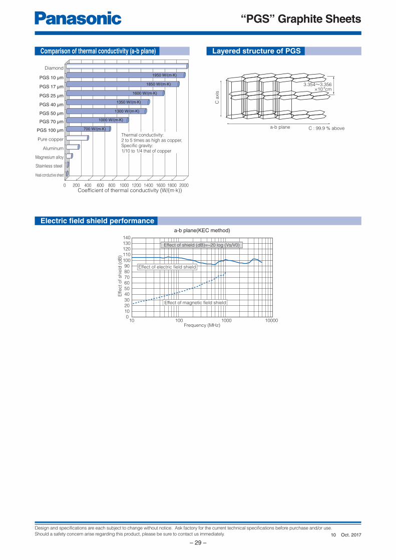
Design and specifications are each subject to change without notice. Ask factory for the current technical specifications before purchase and/or use.
Should a safety concern arise regarding this product, please be sure to contact us immediately.
“PGS” Graphite Sheets
– 29 –
0
10
20
30
40
50
60
70
80
90
100
110
120
130
140
10 100 1000 10000Frequency (MHz)
Effect
of
shie
ld (
dB
)
a-b plane(KEC method)
Effect of magnetic field shield
Effect of electric field shield
Effect of shield (dB)=–20 log (Vs/V0)
a-b plane C : 99.9 % above
3.354~3.356×10⁻⁸cm
C a
xis
0 200 400 600 800 1000 1200 1400 1600 1800 2000
Magnesium alloy
Stainless steel
Aluminum
Pure copper
PGS 100 μm
PGS 70 μm
PGS 50 μm
PGS 10 μm
Diamond
Heat-conductive sheet
1950 W/(m·K)
1300 W/(m·K)
1600 W/(m·K)
1000 W/(m·K)
700 W/(m·K)
PGS 40 μm1350 W/(m·K)
PGS 25 μm
PGS 17 μm1850 W/(m·K)
Thermal conductivity:2 to 5 times as high as copper,Specific gravity:1/10 to 1/4 that of copper
Coefficient of thermal conductivity (W/(m·k))
Comparison of thermal conductivity (a-b plane) Layered structure of PGS
Electric fi eld shield performance
Oct. 201710
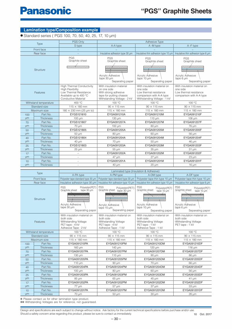
Design and specifications are each subject to change without notice. Ask factory for the current technical specifications before purchase and/or use.
Should a safety concern arise regarding this product, please be sure to contact us immediately.
“PGS” Graphite Sheets
– 30 –
PGSGraphite sheet
Acrylic Adhesivetape 30 μm
Separating paper
PGSGraphite sheet
PGSGraphite sheet
Separating paper
Acrylic Adhesivetape 10 μm
PGSGraphite sheet
Polyester(PET) tape 30 μm
Acrylic Adhesivetape 30 μm
Separating paper
PGSGraphite sheet
Polyester(PET) tape 10 μm
Acrylic Adhesivetape 10 μm
Separating paper
PGSGraphite sheet
Acrylic Adhesivetape 10 μm
Polyester(PET) tape 30 μm
Separating paper
PGSGraphite sheet
Separating paper
Acrylic Adhesivetape 6 μm
PGSGraphite sheet
Polyester(PET) tape 10 μm
Acrylic Adhesivetape 6 μm
Separating paper
Lamination type/Composition example
✽ Please contact us for other lamination type product.✽✽ Withstanding Voltages are for reference, not guaranteed.
TypePGS Only Adhesive Type
S type A-A type A -M type A -F type
Front face – – – –
Rear face – Insulative adhesion type 30 μm Insulative thin adhesion type 10 μm Insulative thin adhesion type 6 μm
Structure
Features
· High Thermal ConductivityHigh Flexibility
· Low Thermal Resistance· Available up to 400 °C· Conductive Material
· With insulation materialon one side
· With strong adhesivetape for putting chassis
· Withstanding Voltage : 2 kV
· With insulation material on one side
· Low thermal resistancecomparison with A-A type
· Withstanding Voltage : 1 kV
· With insulation material on one side
· Low thermal resistancecomparison with A-A type
Withstand temperature 400 °C 100 °C 100 °C 100 °C
Standard size 115 × 180 mm 90 × 115 mm 90 × 115 mm 90 × 115 mm
Maximum size 180 × 230 mm (25 μm to) 115 × 180 mm 115 × 180 mm 115 × 180 mm
100μm
Part No. EYGS121810 EYGA091210A EYGA091210M EYGA091210FThickness 100 μm 130 μm 110 μm 106 μm
70μm
Part No. EYGS121807 EYGA091207A EYGA091207M EYGA091207FThickness 70 μm 100 μm 80 μm 76 μm
50μm
Part No. EYGS121805 EYGA091205A EYGA091205M EYGA091205FThickness 50 μm 80 μm 60 μm 56 μm
40μm
Part No. EYGS121804 EYGA091204A EYGA091204M EYGA091204FThickness 40 μm 70 μm 50 μm 46 μm
25μm
Part No. EYGS121803 EYGA091203A EYGA091203M EYGA091203FThickness 25 μm 55 μm 35 μm 31 μm
17μm
Part No. – EYGA091202A EYGA091202M EYGA091202FThickness – 47 μm 27 μm 23 μm
10μm
Part No. – EYGA091201A EYGA091201M EYGA091201FThickness – 40 μm 20 μm 16 μm
TypeLaminated type (Insulation & Adhesive)
A-PA type A-PM type A-DM type A-DF type
Front face Polyester tape standard type 30 μm Polyester tape standard type 30 μm Polyester tape thin type 10 μm Polyester tape thin type 10 μm
Rear face Insulative adhesion type 30 μm Insulative thin adhesion type 10 μm Insulative thin adhesion type 10 μm Insulative thin adhesion type 6 μm
Structure
Features
· With insulation material on both side
· Withstanding VoltagePET tape : 4 kVAdhesive Tape : 2 kV
· With insulation material on both side
· Withstanding VoltagePET tape : 4 kVAdhesive Tape : 1 kV
· With insulation material on both side
· Withstanding VoltagePET tape : 1 kVAdhesive Tape : 1 kV
· With insulation material on both side
· Withstanding VoltagePET tape : 1 kV
Withstand temperature 100 °C 100 °C 100 °C 100 °C
Standard size 90 × 115 mm 90 × 115 mm 90 × 115 mm 90 × 115 mm
Maximum size 115 × 180 mm 115 × 180 mm 115 × 180 mm 115 × 180 mm
100μm
Part No. EYGA091210PA EYGA091210PM EYGA091210DM EYGA091210DFThickness 160 μm 140 μm 120 μm 116 μm
70μm
Part No. EYGA091207PA EYGA091207PM EYGA091207DM EYGA091207DFThickness 130 μm 110 μm 90 μm 86 μm
50μm
Part No. EYGA091205PA EYGA091205PM EYGA091205DM EYGA091205DFThickness 110 μm 90 μm 70 μm 66 μm
40μm
Part No. EYGA091204PA EYGA091204PM EYGA091204DM EYGA091204DFThickness 100 μm 80 μm 60 μm 56 μm
25μm
Part No. EYGA091203PA EYGA091203PM EYGA091203DM EYGA091203DFThickness 85 μm 65 μm 45 μm 41 μm
17μm
Part No. EYGA091202PA EYGA091202PM EYGA091202DM EYGA091202DFThickness 77 μm 57 μm 37 μm 33 μm
10μm
Part No. EYGA091201PA EYGA091201PM EYGA091201DM EYGA091201DFThickness 70 μm 50 μm 30 μm 26 μm
● Standard series ( PGS 100, 70, 50, 40, 25, 17, 10 μm)
Oct. 201710
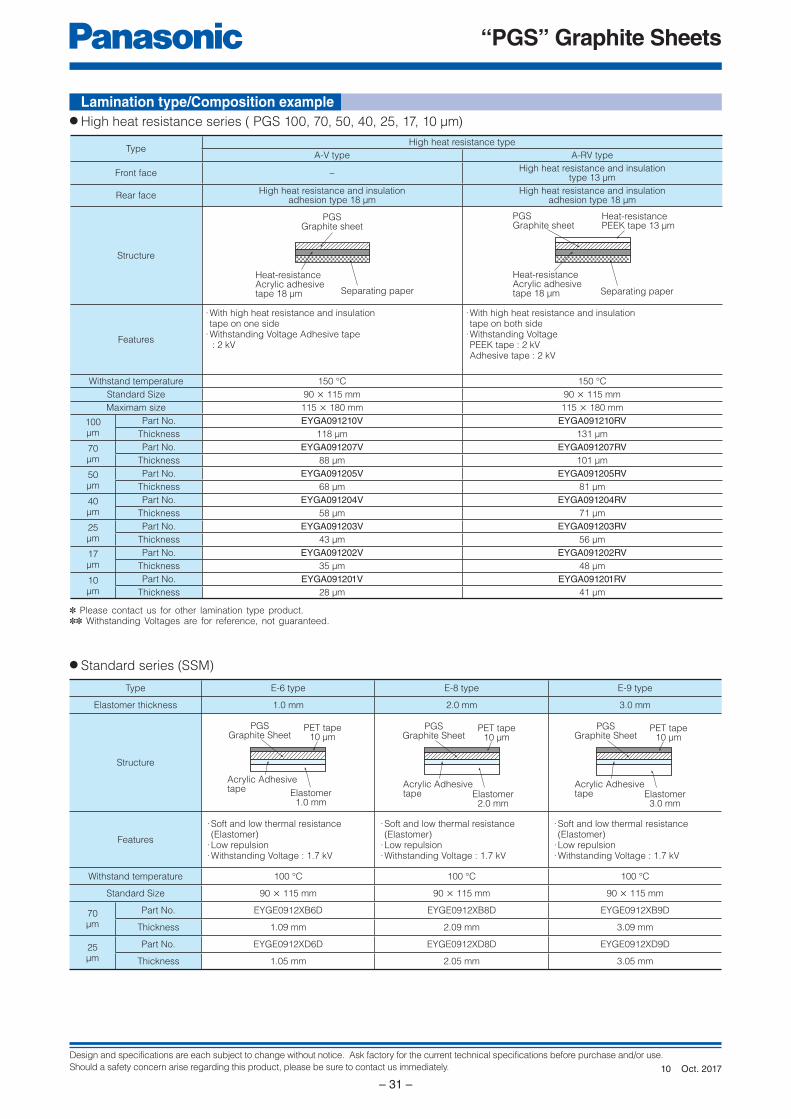
Design and specifications are each subject to change without notice. Ask factory for the current technical specifications before purchase and/or use.
Should a safety concern arise regarding this product, please be sure to contact us immediately.
“PGS” Graphite Sheets
– 31 –
Separating paper
PGSGraphite sheet
Heat-resistance Acrylic adhesivetape 18 μm
Heat-resistance PEEK tape 13 μm
Heat-resistance Acrylic adhesivetape 18 μm Separating paper
PGSGraphite sheet
PET tape10 μm
PGSGraphite Sheet
Acrylic Adhesivetape Elastomer
1.0 mm
PET tape10 μm
PGSGraphite Sheet
Acrylic Adhesivetape Elastomer
2.0 mm
PET tape10 μm
PGSGraphite Sheet
Acrylic Adhesivetape Elastomer
3.0 mm
TypeHigh heat resistance type
A-V type A-RV type
Front face –High heat resistance and insulation
type 13 μm
Rear faceHigh heat resistance and insulation
adhesion type 18 μmHigh heat resistance and insulation
adhesion type 18 μm
Structure
Features
· With high heat resistance and insulationtape on one side
· Withstanding Voltage Adhesive tape : 2 kV
· With high heat resistance and insulationtape on both side
· Withstanding VoltagePEEK tape : 2 kVAdhesive tape : 2 kV
Withstand temperature 150 °C 150 °C
Standard Size 90 × 115 mm 90 × 115 mm
Maximam size 115 × 180 mm 115 × 180 mm
100μm
Part No. EYGA091210V EYGA091210RVThickness 118 μm 131 μm
70μm
Part No. EYGA091207V EYGA091207RVThickness 88 μm 101 μm
50μm
Part No. EYGA091205V EYGA091205RVThickness 68 μm 81 μm
40μm
Part No. EYGA091204V EYGA091204RVThickness 58 μm 71 μm
25μm
Part No. EYGA091203V EYGA091203RVThickness 43 μm 56 μm
17μm
Part No. EYGA091202V EYGA091202RVThickness 35 μm 48 μm
10μm
Part No. EYGA091201V EYGA091201RVThickness 28 μm 41 μm
✽ Please contact us for other lamination type product.✽✽ Withstanding Voltages are for reference, not guaranteed.
● High heat resistance series ( PGS 100, 70, 50, 40, 25, 17, 10 μm)
● Standard series (SSM)
Type E-6 type E-8 type E-9 type
Elastomer thickness 1.0 mm 2.0 mm 3.0 mm
Structure
Features
· Soft and low thermal resistance (Elastomer)
· Low repulsion· Withstanding Voltage : 1.7 kV
· Soft and low thermal resistance (Elastomer)
· Low repulsion· Withstanding Voltage : 1.7 kV
· Soft and low thermal resistance (Elastomer)
· Low repulsion· Withstanding Voltage : 1.7 kV
Withstand temperature 100 °C 100 °C 100 °C
Standard Size 90 × 115 mm 90 × 115 mm 90 × 115 mm
70μm
Part No. EYGE0912XB6D EYGE0912XB8D EYGE0912XB9D
Thickness 1.09 mm 2.09 mm 3.09 mm
25μm
Part No. EYGE0912XD6D EYGE0912XD8D EYGE0912XD9D
Thickness 1.05 mm 2.05 mm 3.05 mm
Lamination type/Composition example
Oct. 201710
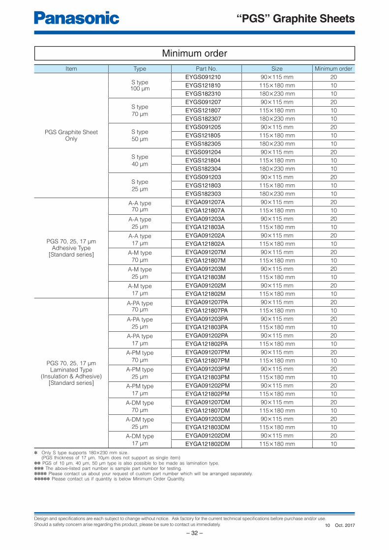
Design and specifications are each subject to change without notice. Ask factory for the current technical specifications before purchase and/or use.
Should a safety concern arise regarding this product, please be sure to contact us immediately.
“PGS” Graphite Sheets
– 32 –
Minimum orderItem Type Part No. Size Minimum order
PGS Graphite SheetOnly
S type100 μm
EYGS091210 90×115 mm 20
EYGS121810 115×180 mm 10
EYGS182310 180×230 mm 10
S type
70 μm
EYGS091207 90×115 mm 20
EYGS121807 115×180 mm 10
EYGS182307 180×230 mm 10
S type
50 μm
EYGS091205 90×115 mm 20
EYGS121805 115×180 mm 10
EYGS182305 180×230 mm 10
S type
40 μm
EYGS091204 90×115 mm 20
EYGS121804 115×180 mm 10
EYGS182304 180×230 mm 10
S type
25 μm
EYGS091203 90×115 mm 20
EYGS121803 115×180 mm 10
EYGS182303 180×230 mm 10
PGS 70, 25, 17 μmAdhesive Type
[Standard series]
A-A type70 μm
EYGA091207A 90×115 mm 20
EYGA121807A 115×180 mm 10
A-A type
25 μm
EYGA091203A 90×115 mm 20
EYGA121803A 115×180 mm 10
A-A type
17 μm
EYGA091202A 90×115 mm 20
EYGA121802A 115×180 mm 10
A-M type
70 μm
EYGA091207M 90×115 mm 20
EYGA121807M 115×180 mm 10
A-M type
25 μm
EYGA091203M 90×115 mm 20
EYGA121803M 115×180 mm 10
A-M type
17 μm
EYGA091202M 90×115 mm 20
EYGA121802M 115×180 mm 10
PGS 70, 25, 17 μmLaminated Type
(Insulation & Adhesive)[Standard series]
A-PA type70 μm
EYGA091207PA 90×115 mm 20
EYGA121807PA 115×180 mm 10
A-PA type
25 μm
EYGA091203PA 90×115 mm 20
EYGA121803PA 115×180 mm 10
A-PA type
17 μm
EYGA091202PA 90×115 mm 20
EYGA121802PA 115×180 mm 10
A-PM type
70 μm
EYGA091207PM 90×115 mm 20
EYGA121807PM 115×180 mm 10
A-PM type
25 μm
EYGA091203PM 90×115 mm 20
EYGA121803PM 115×180 mm 10
A-PM type
17 μm
EYGA091202PM 90×115 mm 20
EYGA121802PM 115×180 mm 10
A-DM type
70 μm
EYGA091207DM 90×115 mm 20
EYGA121807DM 115×180 mm 10
A-DM type
25 μm
EYGA091203DM 90×115 mm 20
EYGA121803DM 115×180 mm 10
A-DM type
17 μm
EYGA091202DM 90×115 mm 20
EYGA121802DM 115×180 mm 10
✽ Only S type supports 180×230 mm size. (PGS thickness of 17 μm, 10μm does not support as single item)✽✽ PGS of 10 μm, 40 μm, 50 μm type is also possible to be made as lamination type.✽✽✽ The above-listed part number is sample part number for testing. ✽✽✽✽ Please contact us about your request of custom part number which will be arranged separately.✽✽✽✽✽ Please contact us if quantity is below Minimum Order Quantity.
Oct. 201710
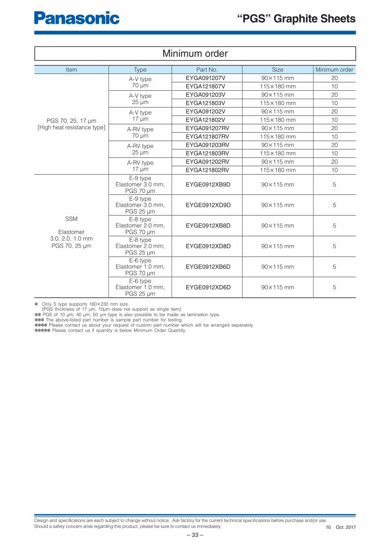
Design and specifications are each subject to change without notice. Ask factory for the current technical specifications before purchase and/or use.
Should a safety concern arise regarding this product, please be sure to contact us immediately.
“PGS” Graphite Sheets
– 33 –
Item Type Part No. Size Minimum order
PGS 70, 25, 17 μm[High heat resistance type]
A-V type70 μm
EYGA091207V 90×115 mm 20
EYGA121807V 115×180 mm 10
A-V type25 μm
EYGA091203V 90×115 mm 20
EYGA121803V 115×180 mm 10
A-V type17 μm
EYGA091202V 90×115 mm 20
EYGA121802V 115×180 mm 10
A-RV type70 μm
EYGA091207RV 90×115 mm 20
EYGA121807RV 115×180 mm 10
A-RV type25 μm
EYGA091203RV 90×115 mm 20
EYGA121803RV 115×180 mm 10
A-RV type17 μm
EYGA091202RV 90×115 mm 20
EYGA121802RV 115×180 mm 10
SSM
Elastomer3.0, 2.0, 1.0 mm
PGS 70, 25 μm
E-9 typeElastomer 3.0 mm,
PGS 70 μmEYGE0912XB9D 90×115 mm 5
E-9 typeElastomer 3.0 mm,
PGS 25 μmEYGE0912XD9D 90×115 mm 5
E-8 typeElastomer 2.0 mm,
PGS 70 μmEYGE0912XB8D 90×115 mm 5
E-8 typeElastomer 2.0 mm,
PGS 25 μmEYGE0912XD8D 90×115 mm 5
E-6 typeElastomer 1.0 mm,
PGS 70 μmEYGE0912XB6D 90×115 mm 5
E-6 typeElastomer 1.0 mm,
PGS 25 μmEYGE0912XD6D 90×115 mm 5
✽ Only S type supports 180×230 mm size. (PGS thickness of 17 μm, 10μm does not support as single item)✽✽ PGS of 10 μm, 40 μm, 50 μm type is also possible to be made as lamination type.✽✽✽ The above-listed part number is sample part number for testing. ✽✽✽✽ Please contact us about your request of custom part number which will be arranged separately.✽✽✽✽✽ Please contact us if quantity is below Minimum Order Quantity.
Minimum order
Oct. 201710
Design and specifications are each subject to change without notice. Ask factory for the current technical specifications before purchase and/or use.
Should a safety concern arise regarding this product, please be sure to contact us immediately.
“PGS” Graphite Sheets
– 34 –
“PGS” (Pyrolytic Graphite Sheet) Heat sink sheet
Handling Precautions
1. Safety Precautions1.1 The PGS shall be used within the specifi ed operating temperature range.1.2 The PGS is soft, do not rub or touch it with rough materials to avoid scratching it.1.3 Lines or folds in the PGS may affect thermal conductivity.1.4 The PGS shall not be used with acid. The PGS shall not be used in contact with a soldering iron at 400 °C or more
1.5 The PGS shall not be exposed to salt water or direct sunlight during use. The PGS shall not be used in corrosive gases (hydrogen sulfi de, sulfurous acid, chlorine, ammonia etc.).
1.6 Our PGS has been developed for general industry applications. Prior to using the PGS for special applications such as medical, work please contact our engineering staff or the factory.
1.7 Never touch a PGS during use because it may be extremely hot.1.8 Since SSM Elastomer resin is soft, please do not store the parts under a load. 1.9 Please do not use the parts in the condition of jamming by contaminants such as metals in SSM Elastomer side.
2. Application notes2.1 Use protective materials when handling and/or applying the PGS, do not use items with sharp edges as they
might tear or puncture the PGS.2.2 The PGS does not work properly if overheated.2.3 Thermal conductivity is dependant on the way it is used. Test the adaptability of PGS to your application before use.
2.4 The PGS has conductivity. If required, the PGS should be provided insulation.
2.5 Long term storage• The PGS shall not be stored under severe conditions of salt water, direct sunlight or corrosive gases (hydrogen
sulfi de, sulfurous acid, chlorine, ammonia etc.).
• The PGS shall not be stored near acid.
• Please store SSM packed at room temperature and humidity while not in use.
2.6 Once applying to the adherent which has dents, SSM Elastomer resin keeps its shape so it cannot be re-ap-plied to different portion.
Safety Precautions
PGS (Pyrolytic Graphite Sheet) Heat sink sheet (hereafter referred to as PGS) may result in accidents or trouble when subjected to severe conditions of electrical, environmental and /or mechanical stress beyond the specified “Rating” and specified “Conditions” found in the Specifications. Please follow the recommendations in “Safety Precautions” and “Application Notes”. Contact our engineering staff or the factory with any questions.
• When using our products, no matter what sort of equipment they might be used for, be sure to make a written
agreement on the specifications with us in advance. The design and specifications in this catalog are subject
to change without prior notice.
• Do not use the products beyond the specifications described in this catalog.
• This catalog explains the quality and performance of the products as individual components. Be fore use, check
and evaluate their operations when installed in your products.
• Install the following systems for a failsafe design to ensure safety if these products are to be used in equipment
where a defect in these products may cause the loss of human life or other significant damage, such as damage
to vehicles (automobile, train, vessel), traffic lights, medical equipment, aerospace equipment, electric heating
appliances, combustion/gas equipment, rotating equipment, and disaster/crime prevention equipment.
✽ Systems equipped with a protection circuit and a protection device
✽ Systems equipped with a redundant circuit or other system to prevent an unsafe status in the event of a single fault
<Package markings>Package markings include the product number, quantity, and country of origin.In principle, the country of origin should be indicated in English.
Aug. 201603
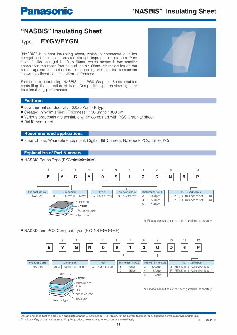
Design and specifications are each subject to change without notice. Ask factory for the current technical specifications before purchase and/or use.
Should a safety concern arise regarding this product, please be sure to contact us immediately.
“NASBIS” Insulating Sheet
– 35 –
E
1
Y
2
G
3 4 5 6 7 8 9 10
9 1 2 Q N 6 P
NASBIS
Product Code Type PET + Adhesive
S
P
PET(10 μm)+Adhesive(10 μm)
PET(30 μm)+Adhesive(10 μm)
Q Normal type
Thickness of PGS
N PGS free type90 mm × 115 mm
Dimension
PET tape
NASBIS
Adhesive tape
Separator
Thickness of NASBIS
3
4
6
1000 μm
500 μm
100 μm
0912
Y 0
11 12
E
1
Y
2
G
3 4 5 6 7 8 9 10 11 12
9 1 2 Q D 6 P
NASBIS
Normal type
Product Code Type PET + Adhesive
S
P
PET(10 μm)+Adhesive(10 μm)
PET(30 μm)+Adhesive(10 μm)
Q Normal type
Thickness of PGS
B
D
70 μm
25 μm
90 mm × 115 mm
Dimension
PET tape
NASBIS
Adhesive tape
Separator
Thickness of NASBIS
3
4
6
1000 μm
500 μm
100 μm
0912
N 0
Adhesive tape6 μm
PGS
“NASBIS” Insulating Sheet
Type: EYGY/EYGN
● Smartphone, Wearable equipment, Digital Still Camera, Notebook PCs, Tablet PCs
● NASBIS Pouch Type (EYGY✽✽✽✽✽✽✽✽)
● NASBIS and PGS Composit Type (EYGN✽✽✽✽✽✽✽✽)
● Low thermal conductivity : 0.020 W/m · K typ. ● Created thin-fi lm sheet ; Thickness : 100 μm to 1000 μm● Various proposals are available when combined with PGS Graphite sheet● RoHS compliant
“NASBIS” is a heat insulating sheet, which is composed of silica aerogel and fiber sheet, created through impregnation process. Pore size of silica aerogel is 10 to 60nm, which means it has smaller space than the mean free path of the air, 68nm. Air molecules do not collide against each other inside the pores, and thus the component shows excellecnt heat insulation performace.
Furthermore, combining NASBIS and PGS Graphite Sheet enables controlling the direction of heat. Composite type provides greater heat insulating performance.
✽ Please consult the other configurations separately.
✽ Please consult the other configurations separately.
Features
Recommended applications
Explanation of Part Numbers
Jun. 201701
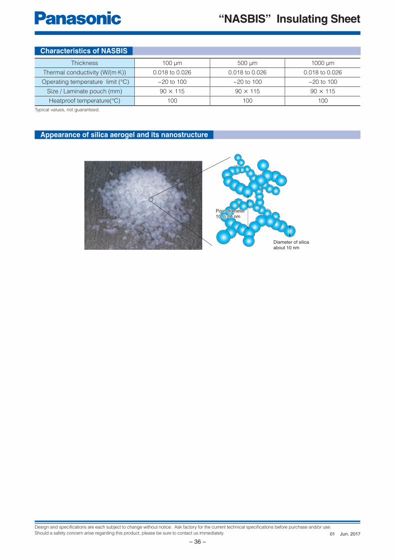
Design and specifications are each subject to change without notice. Ask factory for the current technical specifications before purchase and/or use.
Should a safety concern arise regarding this product, please be sure to contact us immediately.
“NASBIS” Insulating Sheet
– 36 –
Diameter of silicaabout 10 nm
Pore diameter 10 to 60 nmPore diameter 10 to 60 nm
Characteristics of NASBIS
Thickness 100 μm 500 μm 1000 μm
Thermal conductivity (W/(m·K)) 0.018 to 0.026 0.018 to 0.026 0.018 to 0.026
Operating temperature limit (°C) −20 to 100 −20 to 100 −20 to 100
Size / Laminate pouch (mm) 90 × 115 90 × 115 90 × 115
Heatproof temperature(°C) 100 100 100
Appearance of silica aerogel and its nanostructure
Typical values, not guaranteed.
Jun. 201701
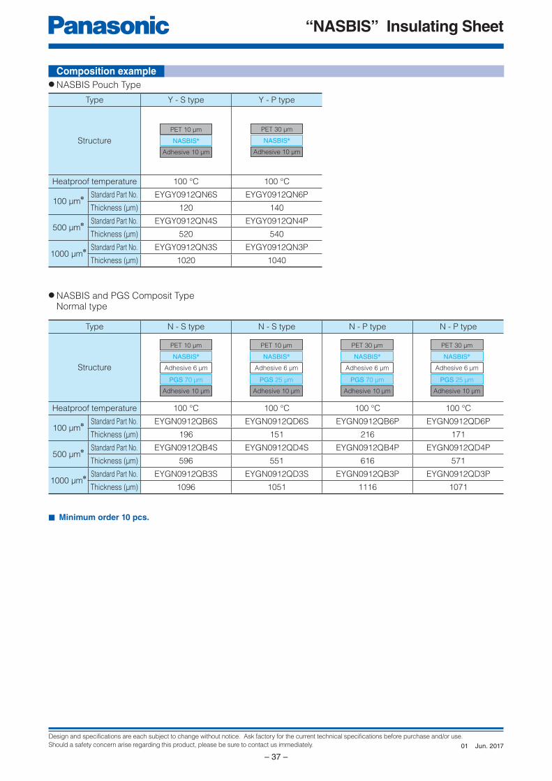
Design and specifications are each subject to change without notice. Ask factory for the current technical specifications before purchase and/or use.
Should a safety concern arise regarding this product, please be sure to contact us immediately.
“NASBIS” Insulating Sheet
– 37 –
PET 10 μm
Adhesive 10 μm
NASBIS✽
PET 30 μm
Adhesive 10 μm
NASBIS✽
PET 10 μm
Adhesive 6 μm
NASBIS✽
Adhesive 10 μm
PGS 70 μm
PET 10 μm
Adhesive 6 μm
NASBIS✽
Adhesive 10 μm
PGS 25 μm
PET 30 μm
Adhesive 6 μm
NASBIS✽
Adhesive 10 μm
PGS 70 μm
PET 30 μm
Adhesive 6 μm
NASBIS✽
Adhesive 10 μm
PGS 25 μm
Composition example
Type Y - S type Y - P type
Structure
Heatproof temperature 100 °C 100 °C
100 μm✽ Standard Part No. EYGY0912QN6S EYGY0912QN6P
Thickness (μm) 120 140
500 μm✽ Standard Part No. EYGY0912QN4S EYGY0912QN4P
Thickness (μm) 520 540
1000 μm✽ Standard Part No. EYGY0912QN3S EYGY0912QN3P
Thickness (μm) 1020 1040
Type N - S type N - S type N - P type N - P type
Structure
Heatproof temperature 100 °C 100 °C 100 °C 100 °C
100 μm✽ Standard Part No. EYGN0912QB6S EYGN0912QD6S EYGN0912QB6P EYGN0912QD6P
Thickness (μm) 196 151 216 171
500 μm✽ Standard Part No. EYGN0912QB4S EYGN0912QD4S EYGN0912QB4P EYGN0912QD4P
Thickness (μm) 596 551 616 571
1000 μm✽ Standard Part No. EYGN0912QB3S EYGN0912QD3S EYGN0912QB3P EYGN0912QD3P
Thickness (μm) 1096 1051 1116 1071
● NASBIS Pouch Type
● NASBIS and PGS Composit Type Normal type
■ Minimum order 10 pcs.
Jun. 201701
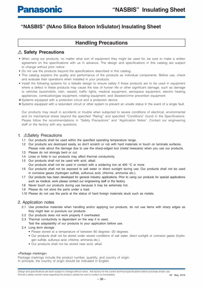
Design and specifications are each subject to change without notice. Ask factory for the current technical specifications before purchase and/or use.
Should a safety concern arise regarding this product, please be sure to contact us immediately.
“NASBIS” Insulating Sheet
– 38 –
“NASBIS” (NAno Silica Baloon InSulator) Insulating Sheet
Handling Precautions
1. Safety Precautions1.1 Our products shall be used within the specifi ed operating temperature range.1.2 Our products are destroyed easily, so don't scratch or rub with hard materials or touch on laminate surfaces. Please note about the damage due to use the sharp-edged tool (metal tweezers) when you use our products.1.3 Please do not strongly bent or cut.1.4 Lines or folds in our products may affect thermal conductivity.1.5 Our products shall not be used with acid, alkali. Our products shall not be used in contact with a soldering iron at 400 °C or more1.6 Our products shall not be exposed to salt water or direct sunlight during use. Our products shall not be used
in corrosive gases (hydrogen sulfi de, sulfurous acid, chlorine, ammonia etc.).1.7 Our products has been developed for general industry applications. Prior to using our products for special applications
such as medical, work please contact our engineering staff or the factory.1.8 Never touch our products during use because it may be extremely hot.1.9 Please do not store the parts under a load. 1.10 Please do not use the parts at the status of hard foreign materials stuck such as metals.
2. Application notes2.1 Use protective materials when handling and/or applying our products, do not use items with sharp edges as
they might tear or puncture our products2.2 Our products does not work properly if overheated.2.3 Thermal conductivity is dependant on the way it is used. Test the adaptability of our products to your application before use.2.4 Long term storage
• Please stored at a temperature of between 80 degrees -20 degrees.
• Our products shall not be stored under severe conditions of salt water, direct sunlight or corrosive gases (hydro-
gen sulfi de, sulfurous acid, chlorine, ammonia etc.).
• Our products shall not be stored near acid, alkali.
Safety Precautions
Our products may result in accidents or trouble when subjected to severe conditions of electrical, environmental
and /or mechanical stress beyond the specified “Rating” and specified “Conditions” found in the Specifications.
Please follow the recommendations in “Safety Precautions” and “Application Notes”. Contact our engineering
staff or the factory with any questions.
• When using our products, no matter what sort of equipment they might be used for, be sure to make a written
agreement on the specifications with us in advance. The design and specifications in this catalog are subject
to change without prior notice.
• Do not use the products beyond the specifications described in this catalog.
• This catalog explains the quality and performance of the products as individual components. Be fore use, check
and evaluate their operations when installed in your products.
• Install the following systems for a failsafe design to ensure safety if these products are to be used in equipment
where a defect in these products may cause the loss of human life or other significant damage, such as damage
to vehicles (automobile, train, vessel), traffic lights, medical equipment, aerospace equipment, electric heating
appliances, combustion/gas equipment, rotating equipment, and disaster/crime prevention equipment.
✽ Systems equipped with a protection circuit and a protection device
✽ Systems equipped with a redundant circuit or other system to prevent an unsafe status in the event of a single fault
<Package markings>Package markings include the product number, quantity, and country of origin.In principle, the country of origin should be indicated in English.
May. 201600
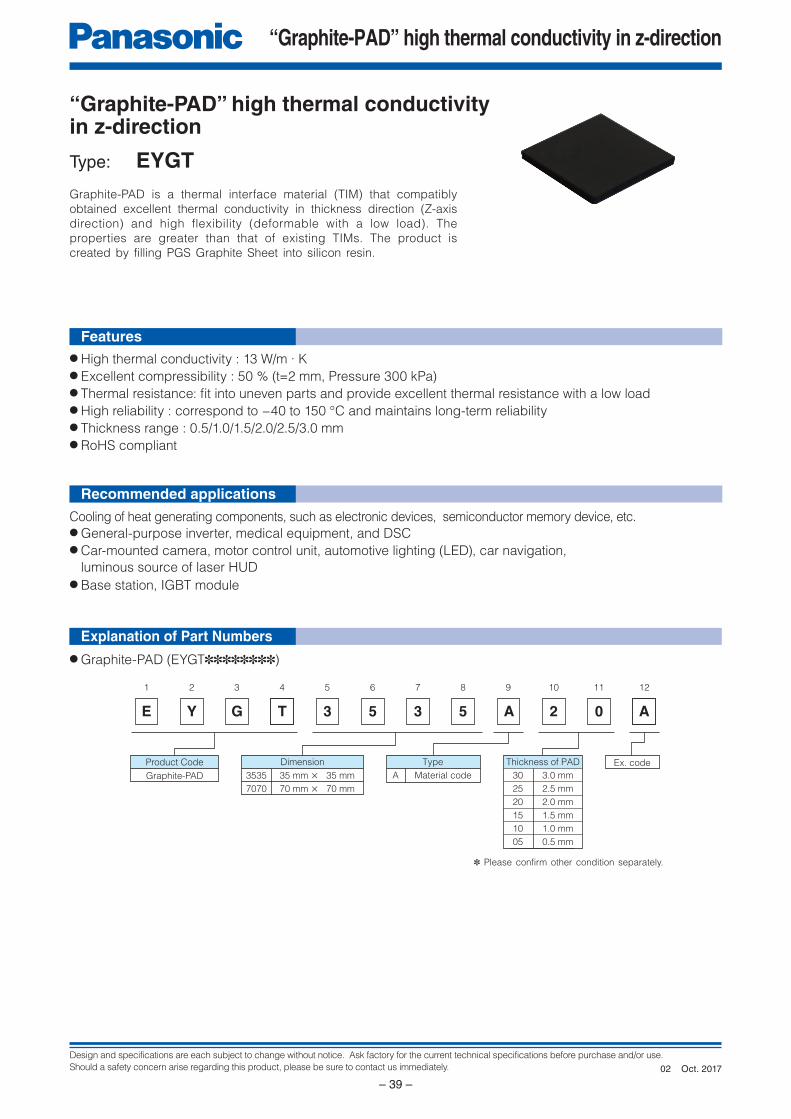
Design and specifications are each subject to change without notice. Ask factory for the current technical specifications before purchase and/or use.
Should a safety concern arise regarding this product, please be sure to contact us immediately.
“Graphite-PAD” high thermal conductivity in z-direction
– 39 –
E
1
Y
2
G
3 4 5 6 7 8 9 10
5
11 12
3 5 A 2 0 AT 3
Type
A Material code 35 mm × 35 mm
70 mm × 70 mm
Dimension Thickness of PAD
30
25
20
15
10
05
3.0 mm
2.5 mm
2.0 mm
1.5 mm
1.0 mm
0.5 mm
3535
7070
Ex. code
Graphite-PAD
Product Code
Cooling of heat generating components, such as electronic devices, semiconductor memory device, etc.● General-purpose inverter, medical equipment, and DSC● Car-mounted camera, motor control unit, automotive lighting (LED), car navigation,
luminous source of laser HUD
● Base station, IGBT module
● High thermal conductivity : 13 W/m ∙ K● Excellent compressibility : 50 % (t=2 mm, Pressure 300 kPa)● Thermal resistance: fi t into uneven parts and provide excellent thermal resistance with a low load● High reliability : correspond to −40 to 150 °C and maintains long-term reliability● Thickness range : 0.5/1.0/1.5/2.0/2.5/3.0 mm● RoHS compliant
Features
Recommended applications
“Graphite-PAD” high thermal conductivity in z-direction
Type: EYGT
● Graphite-PAD (EYGT✽✽✽✽✽✽✽✽)
Graphite-PAD is a thermal interface material (TIM) that compatibly
obtained excellent thermal conductivity in thickness direction (Z-axis
direction) and high flexibility (deformable with a low load). The
properties are greater than that of existing TIMs. The product is
created by filling PGS Graphite Sheet into silicon resin.
✽ Please confirm other condition separately.
Explanation of Part Numbers
Oct. 201702
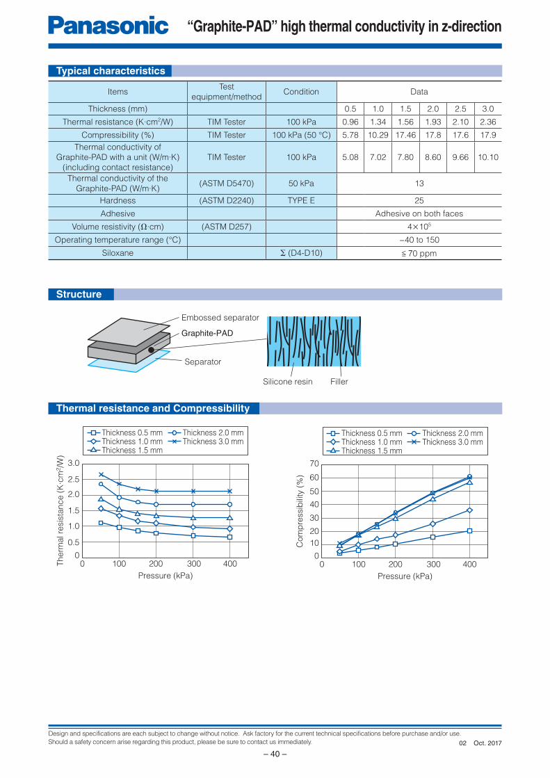
Design and specifications are each subject to change without notice. Ask factory for the current technical specifications before purchase and/or use.
Should a safety concern arise regarding this product, please be sure to contact us immediately.
“Graphite-PAD” high thermal conductivity in z-direction
– 40 –
Embossed separator
Graphite-PAD
Separator
Silicone resin Filler
Pressure (kPa)
Com
pre
ssib
ility
(%
)
10000
10
20
30
40
50
60
70
200 300 400
Thickness 0.5 mmThickness 1.0 mmThickness 1.5 mm
Thickness 2.0 mmThickness 3.0 mm
Pressure (kPa)
Therm
al re
sis
tance (
K∙c
m2/W
)
10000
0.5
1.0
1.5
2.0
2.5
3.0
Thickness 0.5 mm
200 300 400
Thickness 1.0 mmThickness 1.5 mm
Thickness 2.0 mmThickness 3.0 mm
Typical characteristics
Structure
Thermal resistance and Compressibility
ItemsTest
equipment/methodCondition Data
Thickness (mm) 0.5 1.0 1.5 2.0 2.5 3.0
Thermal resistance (K·cm2/W) TIM Tester 100 kPa 0.96 1.34 1.56 1.93 2.10 2.36
Compressibility (%) TIM Tester 100 kPa (50 °C) 5.78 10.29 17.46 17.8 17.6 17.9
Thermal conductivity of
Graphite-PAD with a unit (W/m·K)
(including contact resistance)
TIM Tester 100 kPa 5.08 7.02 7.80 8.60 9.66 10.10
Thermal conductivity of the
Graphite-PAD (W/m·K)(ASTM D5470) 50 kPa 13
Hardness (ASTM D2240) TYPE E 25
Adhesive Adhesive on both faces
Volume resistivity (Ω·cm) (ASTM D257) 4×10⁵
Operating temperature range (°C) −40 to 150
Siloxane Σ (D4-D10) < 70 ppm
Oct. 201702
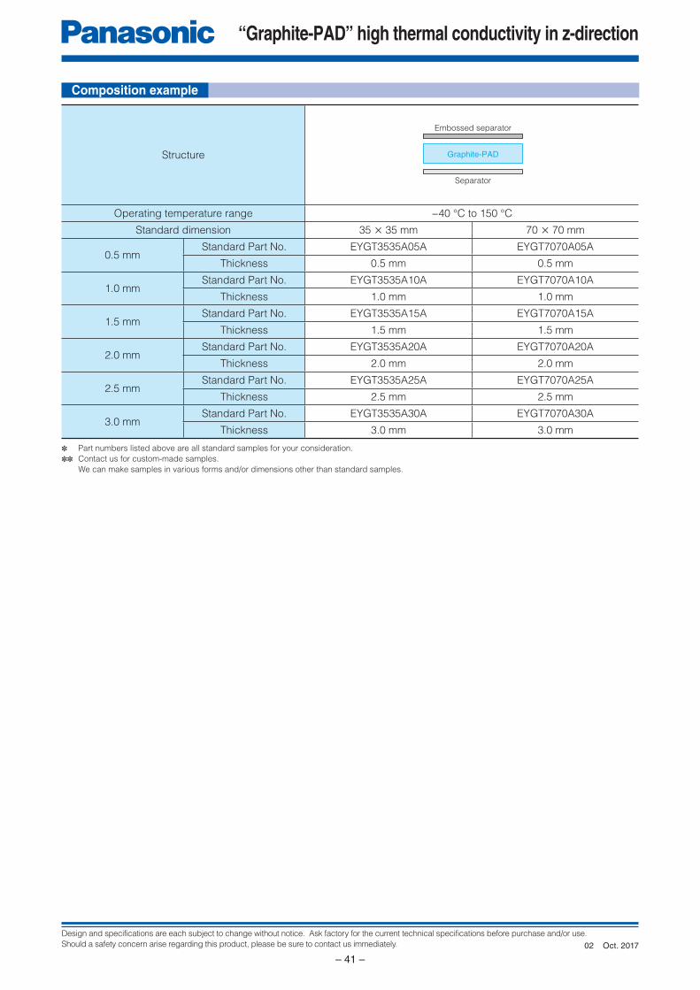
Design and specifications are each subject to change without notice. Ask factory for the current technical specifications before purchase and/or use.
Should a safety concern arise regarding this product, please be sure to contact us immediately.
“Graphite-PAD” high thermal conductivity in z-direction
– 41 –
Embossed separator
Separator
Graphite-PAD
✽ Part numbers listed above are all standard samples for your consideration.
✽✽ Contact us for custom-made samples.
We can make samples in various forms and/or dimensions other than standard samples.
Structure
Operating temperature range −40 °C to 150 °C
Standard dimension 35 × 35 mm 70 × 70 mm
0.5 mmStandard Part No. EYGT3535A05A EYGT7070A05A
Thickness 0.5 mm 0.5 mm
1.0 mmStandard Part No. EYGT3535A10A EYGT7070A10A
Thickness 1.0 mm 1.0 mm
1.5 mmStandard Part No. EYGT3535A15A EYGT7070A15A
Thickness 1.5 mm 1.5 mm
2.0 mmStandard Part No. EYGT3535A20A EYGT7070A20A
Thickness 2.0 mm 2.0 mm
2.5 mmStandard Part No. EYGT3535A25A EYGT7070A25A
Thickness 2.5 mm 2.5 mm
3.0 mmStandard Part No. EYGT3535A30A EYGT7070A30A
Thickness 3.0 mm 3.0 mm
Composition example
Oct. 201702
Design and specifications are each subject to change without notice. Ask factory for the current technical specifications before purchase and/or use.
Should a safety concern arise regarding this product, please be sure to contact us immediately.
“Graphite-PAD” high thermal conductivity in z-direction
– 42 –
“'Graphite-PAD” high thermal conductivity in z-direction
Handling Precautions
1. Safety Precautions1.1 The Graphite-PAD shall be used within the specifi ed operating temperature range.1.2 The Graphite-PAD is soft, do not rub or touch it with rough materials to avoid scratching it.1.3 Lines or folds in the Graphite-PAD may affect thermal conductivity.1.4 The Graphite-PAD shall not be used with acid. The Graphite-PAD shall not be used in contact with a soldering iron at 150 °C or more.1.5 The Graphite-PAD shall not be exposed to salt water or direct sunlight during use. The Graphite-PAD shall not
be used in corrosive gases (hydrogen sulfi de, sulfurous acid, chlorine, ammonia etc.).1.6 Our Graphite-PAD has been developed for general industry applications. Prior to using the Graphite-PAD for
special applications such as medical, work please contact our engineering staff or the factory.1.7 Never touch a Graphite-PAD during use because it may be extremely hot.
2. Application notes2.1 Do not use items with sharp edges as they might tear or puncture the Graphite-PAD.2.2 The Graphite-PAD does not work properly if overheated.2.3 Thermal conductivity is dependant on the way it is used. Test the adaptability of Graphite-PAD to your application before use.2.4 The Graphite-PAD has conductivity. Use the product at a position/place where you do not need any insulation.2.5 Long term storage
• The Graphite-PAD shall not be stored under severe conditions of salt water, direct sunlight or corrosive gases
(hydrogen sulfi de sulfurous acid, chlorine, ammonia etc.).
• The Graphite-PAD shall not be stored near acid.
Safety Precautions
Graphite-PAD may result in accidents or trouble when subjected to severe conditions of electrical, environmental and /or mechanical stress beyond the specified “Rating” and specified “Conditions” found in the Specifications. Please follow the recommendations in “Safety Precautions” and “Application Notes”. Contact our engineering staff or the factory with any questions.
• When using our products, no matter what sort of equipment they might be used for, be sure to make a written
agreement on the specifications with us in advance. The design and specifications in this catalog are subject
to change without prior notice.
• Do not use the products beyond the specifications described in this catalog.
• This catalog explains the quality and performance of the products as individual components. Be fore use, check
and evaluate their operations when installed in your products.
• Install the following systems for a failsafe design to ensure safety if these products are to be used in equipment
where a defect in these products may cause the loss of human life or other significant damage, such as damage
to vehicles (automobile, train, vessel), traffic lights, medical equipment, aerospace equipment, electric heating
appliances, combustion/gas equipment, rotating equipment, and disaster/crime prevention equipment.
✽ Systems equipped with a protection circuit and a protection device
✽ Systems equipped with a redundant circuit or other system to prevent an unsafe status in the event of a single fault
<Package markings>Package markings include the product number, quantity, and country of origin.In principle, the country of origin should be indicated in English.
Aug. 201600
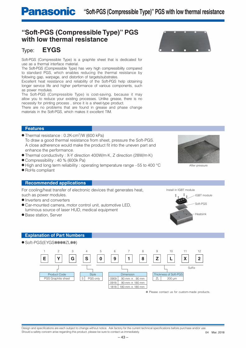
Design and specifications are each subject to change without notice. Ask factory for the current technical specifications before purchase and/or use.
Should a safety concern arise regarding this product, please be sure to contact us immediately.
“Soft-PGS (Compressible Type)” PGS with low thermal resistance
– 43 –
E
1
Y
2
G
3 4 5 6 7 8 9 10
9
11 12
1 8 Z L X 2
90 mm × 90 mm
90 mm × 180 mm
180 mm × 180 mm
Dimension Thickness of Soft-PGS
ZL 200 μm
Suffix
0909
0918
1818
S 0
Style
S PGS onlyPGS Graphite sheet
Product Code
“Soft-PGS (Compressible Type)” PGS with low thermal resistance
Type: EYGS
For cooling/heat transfer of electronic devices that generates heat, such as power modules.● Inverters and converters● Car-mounted camera, motor control unit, automotive LED, luminous source of laser HUD, medical equipment● Base station, Server
● Soft-PGS(EYGS✽✽✽✽ZL✽✽)
● Thermal resistance : 0.2K∙cm2/W (600 kPa) To draw a good thermal resistance from sheet, pressure the Soft-PGS. A close adherence would make the product fi t into the uneven part and enhance the performance.● Thermal conductivity : X-Y direction 400W/m∙K, Z direction (28W/m∙K)● Compressibility : 40 % (600k Pa)● High and long term reliability : operating temperature range –55 to 400 °C● RoHs compliant
Soft-PGS (Compressible Type) is a graphite sheet that is dedicated for use as a thermal interface material.The Soft-PGS (Compressible Type) has very high compressibility compared to standard PGS, which enables reducing the thermal resistance by following gap, warpage, and distortion of targets/substrates.Excellent heat resistance and reliability of the Soft-PGS help obtaining longer service life and higher performance of various components, such as power modules.The Soft-PGS (Compressible Type) is cost-saving, because it may allow you to reduce your existing processes. Unlike grease, there is no necessity for printing process , since it is a sheet-type product.There are no problems that are found in grease and phase change materials in the Soft-PGS, which makes it excellent TIM.
✽ Please contact us for custom-made products.
After pressure
Install in IGBT module
IGBT module
Soft-PGS
Heatsink
Explanation of Part Numbers
Recommended applications
Features
Mar. 201804
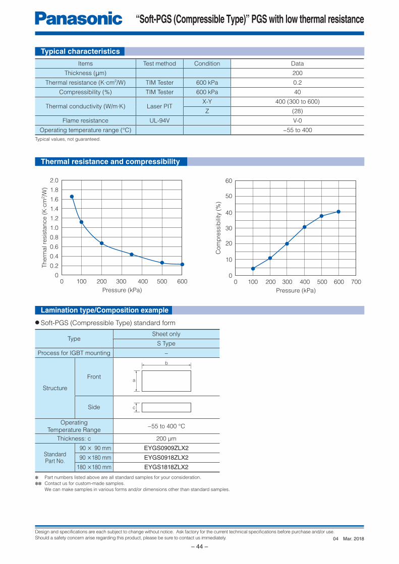
Design and specifications are each subject to change without notice. Ask factory for the current technical specifications before purchase and/or use.
Should a safety concern arise regarding this product, please be sure to contact us immediately.
“Soft-PGS (Compressible Type)” PGS with low thermal resistance
– 44 –
Pressure (kPa)
1000
Com
pre
ssib
ility
(%
)
200 300 400 500 7006000
10
20
30
40
50
60
Pressure (kPa)
1000
Therm
al re
sis
tanc
e (
K∙c
m2/W
)
200 300 400 500 6000
0.2
0.4
0.6
0.8
1.0
1.2
1.4
1.6
1.8
2.0
a
b
c
✽ Part numbers listed above are all standard samples for your consideration.
✽✽ Contact us for custom-made samples.
We can make samples in various forms and/or dimensions other than standard samples.
Typical values, not guaranteed.
Thermal resistance and compressibility
Items Test method Condition Data
Thickness (µm) 200
Thermal resistance (K·cm2/W) TIM Tester 600 kPa 0.2
Compressibility (%) TIM Tester 600 kPa 40
Thermal conductivity (W/m·K) Laser PITX-Y 400 (300 to 600)
Z (28)
Flame resistance UL-94V V-0
Operating temperature range (°C) −55 to 400
TypeSheet only
S Type
Process for IGBT mounting −
Structure
Front
Side
Operating
Temperature Range−55 to 400 °C
Thickness: c 200 μm
Standard Part No.
90 × 90 mm EYGS0909ZLX2
90 ×180 mm EYGS0918ZLX2
180 ×180 mm EYGS1818ZLX2
● Soft-PGS (Compressible Type) standard form
Typical characteristics
Lamination type/Composition example
Mar. 201804
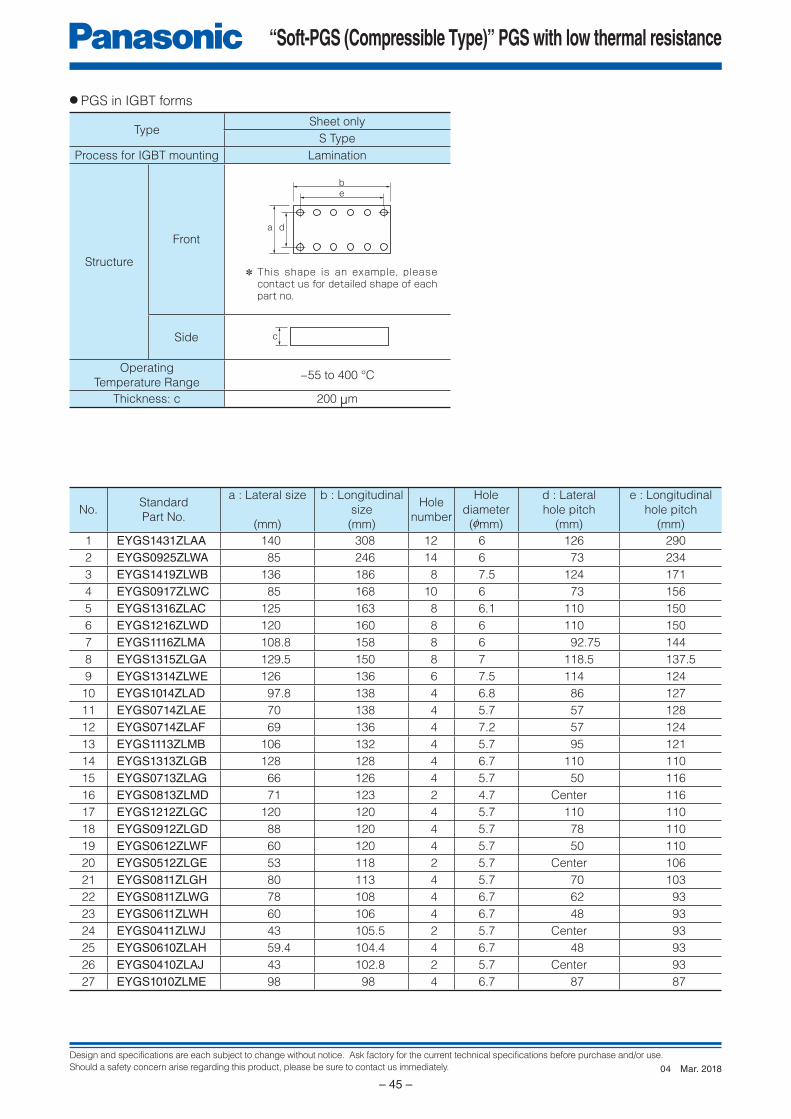
Design and specifications are each subject to change without notice. Ask factory for the current technical specifications before purchase and/or use.
Should a safety concern arise regarding this product, please be sure to contact us immediately.
“Soft-PGS (Compressible Type)” PGS with low thermal resistance
– 45 –
a d
be
c
● PGS in IGBT forms
TypeSheet only
S Type
Process for IGBT mounting Lamination
Structure
Front
Side
Operating
Temperature Range−55 to 400 °C
Thickness: c 200 µm
No.Standard
Part No.
a : Lateral size
(mm)
b : Longitudinal
size
(mm)
Hole
number
Hole
diameter
(0mm)
d : Lateral
hole pitch
(mm)
e : Longitudinal
hole pitch
(mm)1 EYGS1431ZLAA 140 308 12 6 126 290
2 EYGS0925ZLWA 85 246 14 6 73 234
3 EYGS1419ZLWB 136 186 8 7.5 124 171
4 EYGS0917ZLWC 85 168 10 6 73 156
5 EYGS1316ZLAC 125 163 8 6.1 110 150
6 EYGS1216ZLWD 120 160 8 6 110 150
7 EYGS1116ZLMA 108.8 158 8 6 92.75 144
8 EYGS1315ZLGA 129.5 150 8 7 118.5 137.5
9 EYGS1314ZLWE 126 136 6 7.5 114 124
10 EYGS1014ZLAD 97.8 138 4 6.8 86 127
11 EYGS0714ZLAE 70 138 4 5.7 57 128
12 EYGS0714ZLAF 69 136 4 7.2 57 124
13 EYGS1113ZLMB 106 132 4 5.7 95 121
14 EYGS1313ZLGB 128 128 4 6.7 110 110
15 EYGS0713ZLAG 66 126 4 5.7 50 116
16 EYGS0813ZLMD 71 123 2 4.7 Center 116
17 EYGS1212ZLGC 120 120 4 5.7 110 110
18 EYGS0912ZLGD 88 120 4 5.7 78 110
19 EYGS0612ZLWF 60 120 4 5.7 50 110
20 EYGS0512ZLGE 53 118 2 5.7 Center 106
21 EYGS0811ZLGH 80 113 4 5.7 70 103
22 EYGS0811ZLWG 78 108 4 6.7 62 93
23 EYGS0611ZLWH 60 106 4 6.7 48 93
24 EYGS0411ZLWJ 43 105.5 2 5.7 Center 93
25 EYGS0610ZLAH 59.4 104.4 4 6.7 48 93
26 EYGS0410ZLAJ 43 102.8 2 5.7 Center 93
27 EYGS1010ZLME 98 98 4 6.7 87 87
✽ This shape is an example, please contact us for detailed shape of each part no.
Mar. 201804
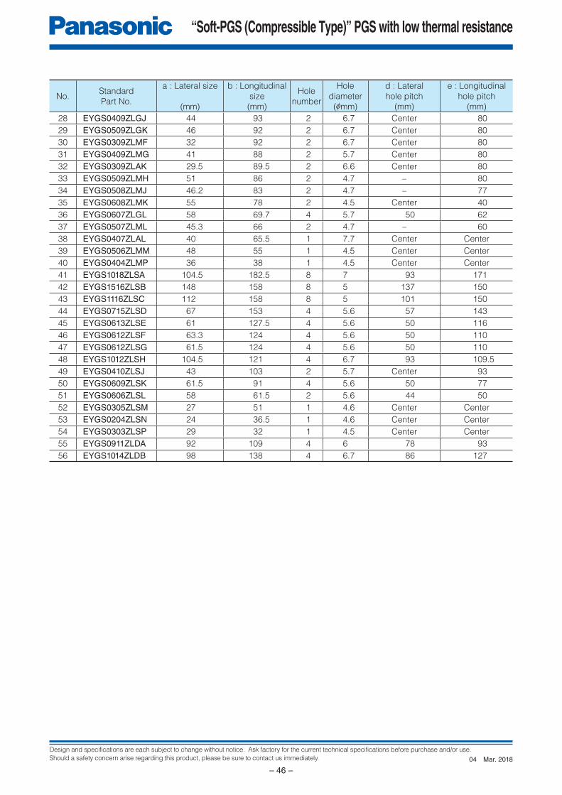
Design and specifications are each subject to change without notice. Ask factory for the current technical specifications before purchase and/or use.
Should a safety concern arise regarding this product, please be sure to contact us immediately.
“Soft-PGS (Compressible Type)” PGS with low thermal resistance
– 46 –
No.Standard
Part No.
a : Lateral size
(mm)
b : Longitudinal
size
(mm)
Hole
number
Hole
diameter
(0mm)
d : Lateral
hole pitch
(mm)
e : Longitudinal
hole pitch
(mm)28 EYGS0409ZLGJ 44 93 2 6.7 Center 80
29 EYGS0509ZLGK 46 92 2 6.7 Center 80
30 EYGS0309ZLMF 32 92 2 6.7 Center 80
31 EYGS0409ZLMG 41 88 2 5.7 Center 80
32 EYGS0309ZLAK 29.5 89.5 2 6.6 Center 80
33 EYGS0509ZLMH 51 86 2 4.7 – 80
34 EYGS0508ZLMJ 46.2 83 2 4.7 – 77
35 EYGS0608ZLMK 55 78 2 4.5 Center 40
36 EYGS0607ZLGL 58 69.7 4 5.7 50 62
37 EYGS0507ZLML 45.3 66 2 4.7 – 60
38 EYGS0407ZLAL 40 65.5 1 7.7 Center Center
39 EYGS0506ZLMM 48 55 1 4.5 Center Center
40 EYGS0404ZLMP 36 38 1 4.5 Center Center
41 EYGS1018ZLSA 104.5 182.5 8 7 93 171
42 EYGS1516ZLSB 148 158 8 5 137 150
43 EYGS1116ZLSC 112 158 8 5 101 150
44 EYGS0715ZLSD 67 153 4 5.6 57 143
45 EYGS0613ZLSE 61 127.5 4 5.6 50 116
46 EYGS0612ZLSF 63.3 124 4 5.6 50 110
47 EYGS0612ZLSG 61.5 124 4 5.6 50 110
48 EYGS1012ZLSH 104.5 121 4 6.7 93 109.5
49 EYGS0410ZLSJ 43 103 2 5.7 Center 93
50 EYGS0609ZLSK 61.5 91 4 5.6 50 77
51 EYGS0606ZLSL 58 61.5 2 5.6 44 50
52 EYGS0305ZLSM 27 51 1 4.6 Center Center
53 EYGS0204ZLSN 24 36.5 1 4.6 Center Center
54 EYGS0303ZLSP 29 32 1 4.5 Center Center
55 EYGS0911ZLDA 92 109 4 6 78 93
56 EYGS1014ZLDB 98 138 4 6.7 86 127
Mar. 201804
Design and specifications are each subject to change without notice. Ask factory for the current technical specifications before purchase and/or use.
Should a safety concern arise regarding this product, please be sure to contact us immediately.
“Soft-PGS (Compressible Type)” PGS with low thermal resistance
– 47 –
“Soft-PGS (Compressible Type)” PGS with low thermal resistance
Handling Precautions
1. Safety Precautions1.1 The Soft-PGS (Compressible Type) shall be used within the specifi ed operating temperature range.1.2 The Soft-PGS (Compressible Type) is soft and liable to be scratched, do not rub or touch it with rough materials to
avoid scratching it.1.3 Lines or folds in the Soft-PGS (Compressible Type) may affect thermal conductivity.1.4 The Soft-PGS (Compressible Type) shall not be used with acid. The Soft-PGS (Compressible Type) shall not be used in contact with a soldering iron at 400 °C or more.1.5 The Soft-PGS (Compressible Type) shall not be exposed to salt water or direct sunlight during use. The Soft-PGS
(Compressible Type) shall not be used in corrosive gases (hydrogen sulfi de, sulfurous acid, chlorine, ammonia etc.).1.6 Our Soft-PGS (Compressible Type) has been developed for general industry applications. Prior to using the Soft-PGS
(Compressible Type) for special applications such as medical, work please contact our engineering staff or the factory.1.7 Never touch a Soft-PGS (Compressible Type) during use because it may be extremely hot.
2. Application notes2.1 Do not use items with sharp edges as they might tear or puncture the Soft-PGS (Compressible Type).2.2 Force applied in peeling direction can cause delamination of the Soft-PGS (Compressible Type), so give a careful
consideration when designing a product.2.3 The Soft-PGS (Compressible Type) does not work properly if overheated.2.4 Thermal resistance and thermal conductivity is dependant on the way it is used. Test the adaptability of Soft-PGS (Compressible Type) to your application before use.2.5 The Soft-PGS (Compressible Type) has conductivity. Use the product at a position/place where you do not need
any insulation.2.6 Long term storage
• The Soft-PGS (Compressible Type) shall not be stored under severe conditions of salt water, direct sunlight
or corrosive gases
(hydrogen sulfi de sulfurous acid, chlorine, ammonia etc.).
• The Soft-PGS (Compressible Type) shall not be stored near acid.
Safety Precautions
Soft-PGS (Compressible Type) may result in accidents or trouble when subjected to severe conditions of electrical, environmental and /or mechanical stress beyond the specified “Rating” and specified “Conditions” found in the Specifications. Please follow the recommendations in “Safety Precautions” and “Application Notes”. Contact our engineering staff or the factory with any questions.
• When using our products, no matter what sort of equipment they might be used for, be sure to make a written
agreement on the specifications with us in advance. The design and specifications in this catalog are subject
to change without prior notice.
• Do not use the products beyond the specifications described in this catalog.
• This catalog explains the quality and performance of the products as individual components. Be fore use, check
and evaluate their operations when installed in your products.
• Install the following systems for a failsafe design to ensure safety if these products are to be used in equipment
where a defect in these products may cause the loss of human life or other significant damage, such as damage
to vehicles (automobile, train, vessel), traffic lights, medical equipment, aerospace equipment, electric heating
appliances, combustion/gas equipment, rotating equipment, and disaster/crime prevention equipment.
✽ Systems equipped with a protection circuit and a protection device
✽ Systems equipped with a redundant circuit or other system to prevent an unsafe status in the event of a single fault
<Package markings>Package markings include the product number, quantity, and country of origin.In principle, the country of origin should be indicated in English.
Nov. 201601
● Please contact ● Factory
1. The electronic components contained in this catalog are designed and produced for use in home electric appliances, office equipment, information equipment, communications equipment, and other general purpose electronic devices.
Before use of any of these components for equipment that requires a high degree of safety, such as medical instruments, aerospace equipment, disaster-prevention equipment, security equipment, vehicles (automobile, train, vessel),
please be sure to contact our sales representative.2. When applying one of these components for equipment requiring a high degree of safety, no matter what sort of application it might be, be sure to install a protective
circuit or redundancy arrangement to enhance the safety of your equipment. In addition, please carry out the safety test on your own responsibility.3. When using our products, no matter what sort of equipment they might be used for, be sure to make a written agreement on the specifications with us in advance. 4. Technical information contained in this catalog is intended to convey examples of typical performances and/or applications and is not intended to make any
warranty with respect to the intellectual property rights or any other related rights of our company or any third parties nor grant any license under such rights. 5. In order to export products in this catalog, the exporter may be subject to the export license requirement under the Foreign Exchange and Foreign Trade Law of
Japan.6. No ozone-depleting substances (ODSs) under the Montreal Protocol are used in the manufacturing processes of Automotive & Industrial Systems Company, Panasonic
Corporation.
CAUTION AND WARNING
The information in this catalog is valid as of March. 2018.
Device Solutions Business DivisionAutomotive & Industrial Systems Company Panasonic Corporation1006 Kadoma, Kadoma City, Osaka 571-8506, JAPAN