Embed Size (px)
Citation preview
TECHNICAL INFORMATION
• SURFACE TREATEMENT
• LIFE SPAN OF GALVANIZATION TREATEMENT
• DEFINITION OF CABLE TRAYS TYPE
• CALCULATION OF CABLE TRAYS WIDTH
• CALCULATION OF CABLE TRAYS GAUGE
• CALCULATION OF DISTANCE BETWEEN SUPPORTS
• DEFINITION OF TYPES OF SUPPORTS
0/5
www.chorus.ro
0/6
This catalogue contains all items of our standard program of cable trays, cable ladders, supports, pipe clamps e.t.c.
PROTECTION AGAINST CORROSION
All our items and according to the conditions and requirements can be delivered with various types of protection against corrosion, such as :
A. Pre-galvanized sheet steel ( Continuously hot-dip zinc coated mild steel strip and sheet for cold forming) acc. to EN 10142. Designation (PG) in our catalogue. This galvanized steel sheet is obtained by immersing a soft steel sheet in a zinc bath at temperatures of 450 oC to 460 oC. The zinc coating acquired that way is 275 g/m2 on both sides, which corresponds to a thickness of 21 μm. When a galvanized sheet is punched or cut the edges of the metal are protected by the formation of zinc hydroxide. Thus pre-galvanized items are suitable for installation in almost dry indoor atmosphere.
B. Hot-dip galvanized after manufacture (Hot dip galvanized coating on fabricated iron and steel articles) acc. to EN ISO 1461. Designation (DG). Items are made of bright quality cold rolled sheet steel which after manufacture are dipped one by one into a liquid zinc bath (temperatures 450 oC to 460 oC). Thus the item, including all cut edges, is being coated with a homogenous zinc layer of 350 – 420 g/m2 on both sides (= 50 – 60 μm). Items made according to this method have a much greater resistance to corrosion compared to pre-galvanized items, making them suitable for installation outdoors or in humid indoor conditions.
C. Electro plated after manufacture acc. to DIN 50961. Designation (EG). Items are made of bright quality cold rolled sheet steel which after manufacture are zinc electro plated. Thus the items, including all cut edges, are being coated with a homogenous zinc layer of appr. 10 μm making them suitable for installation in almost dry indoor atmosphere.
D. Bolts, nuts, washers, threaded rods e.t.c are usually delivered zinc electroplated acc. to relevant DIN specifications (DIN 934, DIN 975 e.t.c.)
E. Some items can be delivered made of stainless steel sheet steel upon request.
F. Hot dipped galvanized items can be delivered with an additional coating as follows: - Surface preparation according to ISO 12944 Part 4. - Prime coat: a layer of min. 15 μm wash primer. - Intermediate coat : application of a layer of min 50 μm with 2 components
polyamide cured Epoxy acc, to MIL-C 82407, B-class spec. - Top coat : application of a layer of min 75 μm with 2 components polyurethane
polyester resins, cured by aliphatic isocyanate resin according to MIL-C-85285 Total coating thickness: 60 μm zinc + 140 μm additional coating = 200 μm
GENERAL INFORMATION
www.chorus.ro
0/7
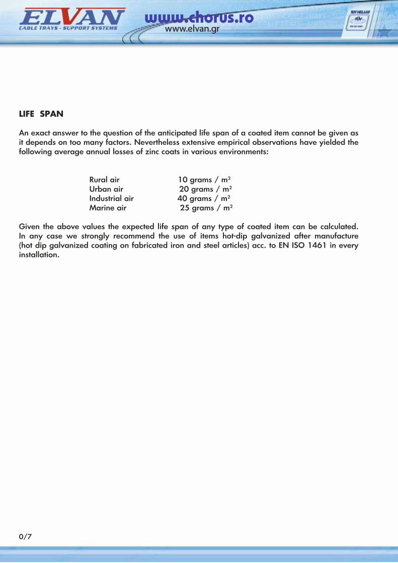
LIFE SPAN
An exact answer to the question of the anticipated life span of a coated item cannot be given as it depends on too many factors. Nevertheless extensive empirical observations have yielded the following average annual losses of zinc coats in various environments:
Rural air 10 grams / m2
Urban air 20 grams / m2
Industrial air 40 grams / m2
Marine air 25 grams / m2
Given the above values the expected life span of any type of coated item can be calculated. In any case we strongly recommend the use of items hot-dip galvanized after manufacture (hot dip galvanized coating on fabricated iron and steel articles) acc. to EN ISO 1461 in every installation.
www.chorus.ro
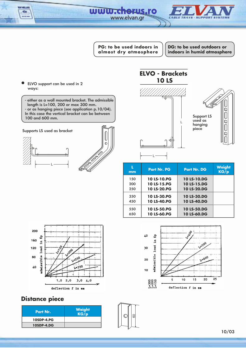
Distance piece
Part Nr. WeightKG/p
10SDP-4.PG
10SDP-4.DG
DG: to be used outdoors or indoors in humid atmosphere
10/03
- either as a wall mounted bracket. The admissible length is L=100, 200 or max 300 mm.
- or as hanging piece (see application p.10/04). In this case the vertical bracket can be between 100 and 600 mm.
• ELVO support can be used in 2 ways:
Lmm Part Nr. PG Part Nr. DG Weight
KG/p
150200250
10 LS-10.PG10 LS-15.PG10 LS-20.PG
10 LS-10.DG10 LS-15.DG10 LS-20.DG
350450
10 LS-30.PG10 LS-40.PG
10 LS-30.DG10 LS-40.DG
550650
10 LS-50.PG10 LS-60.PG
10 LS-50.DG10 LS-60.DG
Supports LS used as bracket
PG: to be used indoors in almost dry atmosphere
ELVO - Brackets 10 LS
Support LSused as hangingpiece
www.chorus.ro
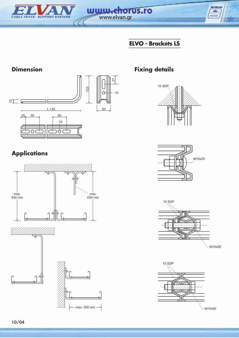
ELVO - Brackets LS
Dimension Fixing details
Applications
10/04
www.chorus.ro
10/04α
PG: to be used indoors in almost dry atmosphere
DG: to be used outdoors or indoors in humid atmosphere
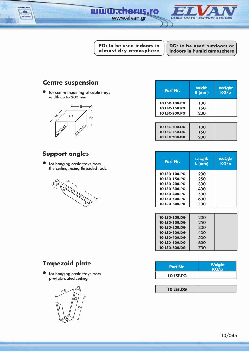
Part Nr. WeightKG/p
10 LSE.PG
10 LSE.DG
Part Nr. WidthB (mm)
Weight KG/p
10 LSC-100.PG10 LSC-150.PG10 LSC-200.PG
100150200
10 LSC-100.DG10 LSC-150.DG10 LSC-200.DG
100150200
Part Nr. LengthL (mm)
Weight KG/p
10 LSD-100.PG10 LSD-150.PG10 LSD-200.PG10 LSD-300.PG10 LSD-400.PG10 LSD-500.PG10 LSD-600.PG
200250300400500600700
10 LSD-100.DG10 LSD-150.DG10 LSD-200.DG10 LSD-300.DG10 LSD-400.DG10 LSD-500.DG10 LSD-600.DG
200250300400500600700
Centre suspension
• for centre mounting of cable trays width up to 200 mm.
Τrapezoid plate
• for hanging cable trays from pre-fabricated ceiling
Support angles
• for hanging cable trays from the ceiling, using threaded rods.
www.chorus.ro
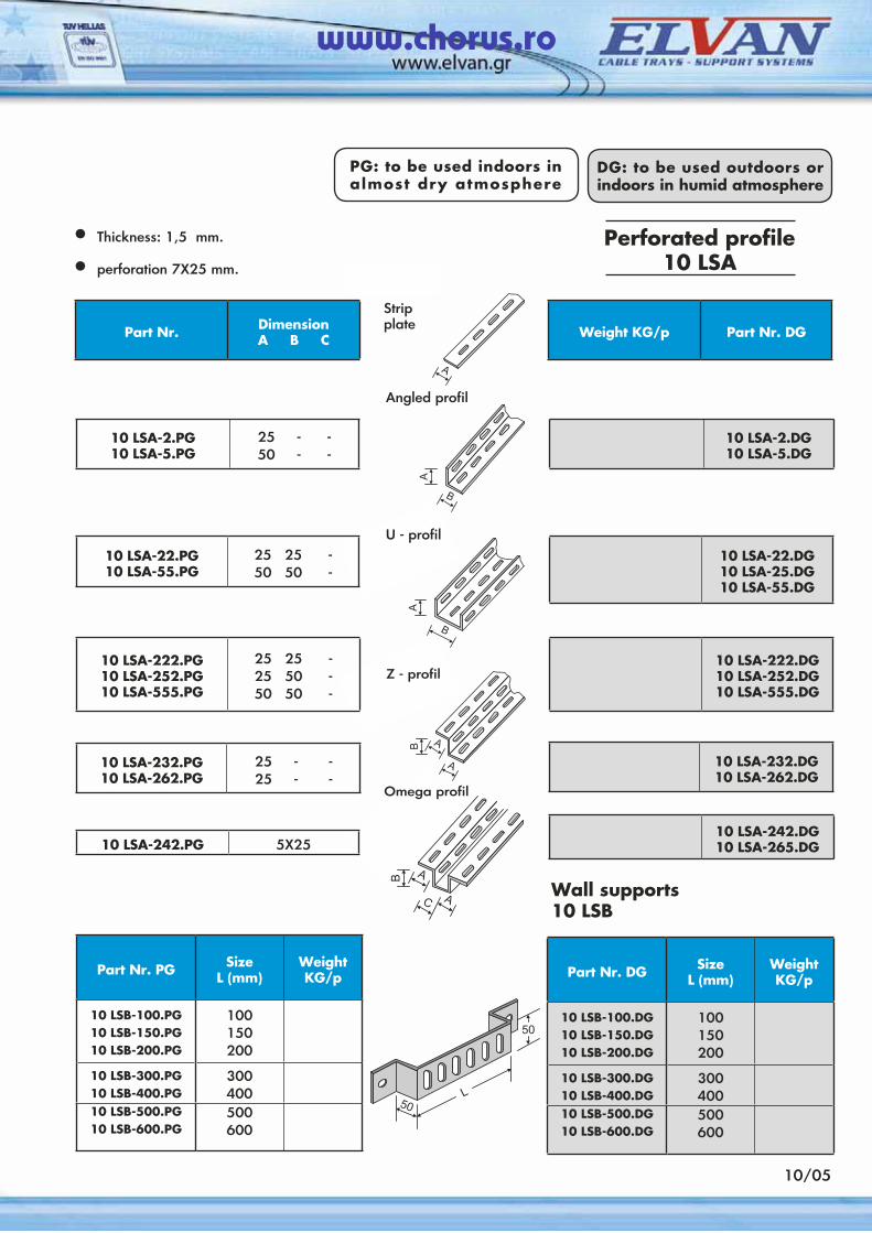
• Thickness: 1,5 mm.
• perforation 7X25 mm.
Wall supports 10 LSB
Perforated profile10 LSA
Part Nr. DimensionΑ Β C
10 LSA-2.PG10 LSA-5.PG
25 - -50 - -
10 LSA-22.PG10 LSA-55.PG
25 25 -50 50 -
10 LSA-222.PG10 LSA-252.PG10 LSA-555.PG
25 25 -25 50 -50 50 -
10 LSA-232.PG10 LSA-262.PG
25 - -25 - -
10 LSA-242.PG 5X25
Part Nr. PG SizeL (mm)
Weight KG/p
10 LSB-100.PG10 LSB-150.PG10 LSB-200.PG
100150200
10 LSB-300.PG10 LSB-400.PG
300400
10 LSB-500.PG10 LSB-600.PG
500600
Weight KG/p Part Nr. DG
10 LSA-2.DG10 LSA-5.DG
10 LSA-22.DG10 LSA-25.DG10 LSA-55.DG
10 LSA-222.DG10 LSA-252.DG10 LSA-555.DG
10 LSA-232.DG10 LSA-262.DG
10 LSA-242.DG10 LSA-265.DG
Part Nr. DG SizeL (mm)
Weight KG/p
10 LSB-100.DG10 LSB-150.DG10 LSB-200.DG
100150200
10 LSB-300.DG10 LSB-400.DG
300400
10 LSB-500.DG10 LSB-600.DG
500600
10/05
PG: to be used indoors in almost dry atmosphere
DG: to be used outdoors or indoors in humid atmosphere
U - profil
Z - profil
Strip plate
Angled profil
Omega profil
www.chorus.ro
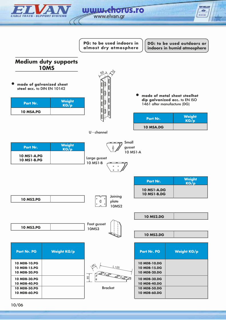
Medium duty supports 10MS
• made of galvanized sheet steel acc. to DIN EN 10142
U - channel
• made of metal sheet steelhot dip galvanized acc. to EN ISO 1461 after manufacture (DG) Part Nr. Weight
KG/p
10 MSA.PG
Part Nr. WeightKG/p
10 MS1-A.PG10 MS1-B.PG
10 MS2.PG
10 MS3.PG
Part Nr. PG Weight KG/p
10 MDB-10.PG10 MDB-15.PG10 MDB-20.PG
10 MDB-30.PG10 MDB-40.PG10 MDB-50.PG10 MDB-60.PG
10/06
Small gusset 10 MS1-A
Foot gusset 10MS3
Bracket
Part Nr. WeightKG/p
10 MSA.DG
Part Nr. WeightKG/p
10 MS1-A.DG10 MS1-B.DG
10 MS2.DG
10 MS3.DG
Part Nr. PG Weight KG/p
10 MDB-10.DG10 MDB-15.DG10 MDB-20.DG
10 MDB-30.DG10 MDB-40.DG10 MDB-50.DG10 MDB-60.DG
Large gusset 10 MS1-B
Joining plate 10MS2
PG: to be used indoors in almost dry atmosphere
DG: to be used outdoors or indoors in humid atmosphere
www.chorus.ro
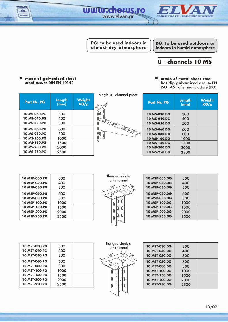
U - channels 10 MS
• made of galvanized sheet steel acc. to DIN EN 10142
• made of metal sheet steel hot dip galvanized acc. to EN ISO 1461 after manufacture (DG)
single u - channel piece
Part Nr. PG Length(mm)
Weight KG/p
10 MS-030.PG10 MS-040.PG10 MS-050.PG
300400500
10 MS-060.PG10 MS-080.PG10 MS-100.PG
600800
100010 MS-150.PG10 MS-200.PG10 MS-250.PG
150020002500
flanged single u - channel
flanged doubleu - channel
10 MSP-030.PG10 MSP-040.PG10 MSP-050.PG
300400500
10 MSP-060.PG10 MSP-080.PG10 MSP-100.PG
600800
100010 MSP-150.PG10 MSP-200.PG10 MSP-250.PG
150020002500
10 MST-030.PG10 MST-040.PG10 MST-050.PG
300400500
10 MST-060.PG10 MST-080.PG10 MST-100.PG
600800
100010 MST-150.PG10 MST-200.PG10 MST-250.PG
150020002500
Part Nr. PG Length(mm)
Weight KG/p
10 MS-030.DG10 MS-040.DG10 MS-050.DG
300400500
10 MS-060.DG10 MS-080.DG10 MS-100.DG
600800
100010 MS-150.DG10 MS-200.DG10 MS-250.DG
150020002500
10 MSP-030.DG10 MSP-040.DG10 MSP-050.DG
300400500
10 MSP-050.DG10 MSP-080.DG10 MSP-100.DG
600800
100010 MSP-150.DG10 MSP-200.DG10 MSP-250.DG
150020002500
10 MST-030.DG10 MST-040.DG10 MST-050.DG
300400500
10 MST-050.DG10 MST-080.DG10 MST-100.DG
600800
100010 MST-150.DG10 MST-200.DG10 MST-250.DG
150020002500
10/07
PG: to be used indoors in almost dry atmosphere
DG: to be used outdoors or indoors in humid atmosphere
www.chorus.ro
10 MSB
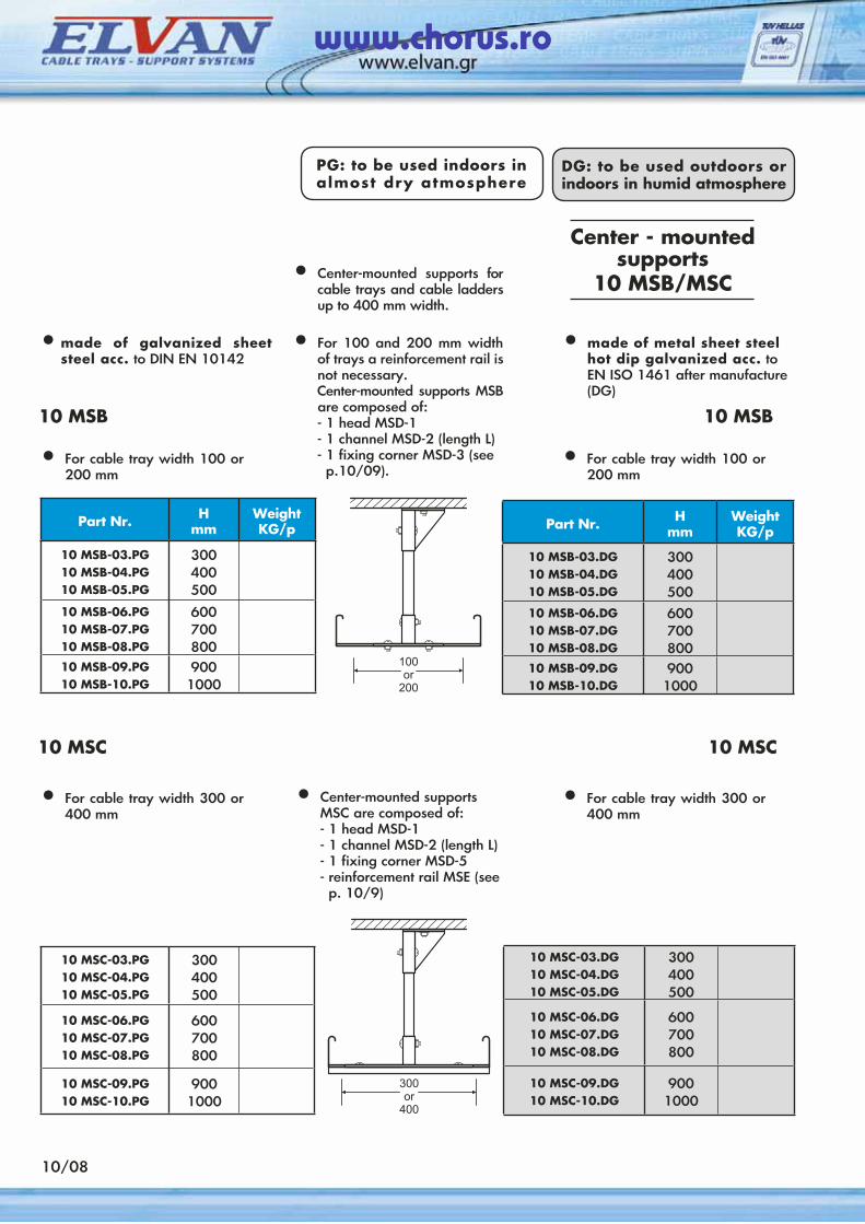
Center - mounted supports
10 MSB/MSC
• made of galvanized sheet steel acc. to DIN EN 10142
• Center-mounted supports for cable trays and cable ladders up to 400 mm width.
• For 100 and 200 mm width of trays a reinforcement rail is not necessary.
Center-mounted supports MSB are composed of:
- 1 head MSD-1 - 1 channel MSD-2 (length L) - 1 fixing corner MSD-3 (see
p.10/09).
Part Nr. Ηmm
Weight KG/p
10 MSB-03.PG10 MSB-04.PG10 MSB-05.PG
300400500
10 MSB-06.PG10 MSB-07.PG10 MSB-08.PG
600700800
10 MSB-09.PG10 MSB-10.PG
9001000
• For cable tray width 100 or 200 mm
10 MSC-03.PG10 MSC-04.PG10 MSC-05.PG
300400500
10 MSC-06.PG10 MSC-07.PG10 MSC-08.PG
600700800
10 MSC-09.PG10 MSC-10.PG
9001000
10/08
• made of metal sheet steel hot dip galvanized acc. to EN ISO 1461 after manufacture (DG)
10 MSB
Part Nr. Ηmm
Weight KG/p
10 MSB-03.DG10 MSB-04.DG10 MSB-05.DG
300400500
10 MSB-06.DG10 MSB-07.DG10 MSB-08.DG
600700800
10 MSB-09.DG10 MSB-10.DG
9001000
10 MSC-03.DG10 MSC-04.DG10 MSC-05.DG
300400500
10 MSC-06.DG10 MSC-07.DG10 MSC-08.DG
600700800
10 MSC-09.DG10 MSC-10.DG
9001000
10 MSC
• Center-mounted supports MSC are composed of:
- 1 head MSD-1 - 1 channel MSD-2 (length L) - 1 fixing corner MSD-5 - reinforcement rail MSE (see
p. 10/9)
10 MSC
PG: to be used indoors in almost dry atmosphere
DG: to be used outdoors or indoors in humid atmosphere
• For cable tray width 100 or 200 mm
• For cable tray width 300 or 400 mm
• For cable tray width 300 or 400 mm
www.chorus.ro
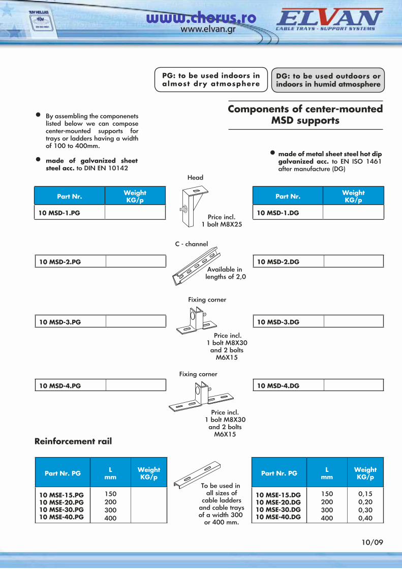
Head
Components of center-mounted MSD supports
Reinforcement rail
• By assembling the componenets listed below we can compose center-mounted supports for trays or ladders having a width of 100 to 400mm.
• made of galvanized sheet steel acc. to DIN EN 10142
Part Nr. WeightKG/p
10 MSD-1.DG
10 MSD-2.DG
Part Nr. PG Lmm
Weight KG/p
10 MSE-15.DG10 MSE-20.DG10 MSE-30.DG10 MSE-40.DG
150200300400
0,150,200,300,40
10 MSD-3.DG
10 MSD-4.DG
• made of metal sheet steel hot dip galvanized acc. to EN ISO 1461 after manufacture (DG)
10/09
Part Nr. PG Lmm
Weight KG/p
10 MSE-15.PG10 MSE-20.PG10 MSE-30.PG10 MSE-40.PG
150200300400
Part Nr. WeightKG/p
10 MSD-1.PG
10 MSD-2.PG
10 MSD-3.PG
10 MSD-4.PG
PG: to be used indoors in almost dry atmosphere
DG: to be used outdoors or indoors in humid atmosphere
Price incl.1 bolt M8X25
C - channel
Available in lengths of 2,0
Fixing corner
Price incl.1 bolt M8X30and 2 bolts
M6X15
Fixing corner
Price incl.1 bolt M8X30and 2 bolts
M6X15
To be used in all sizes of
cable ladders and cable trays of a width 300 or 400 mm.
www.chorus.ro
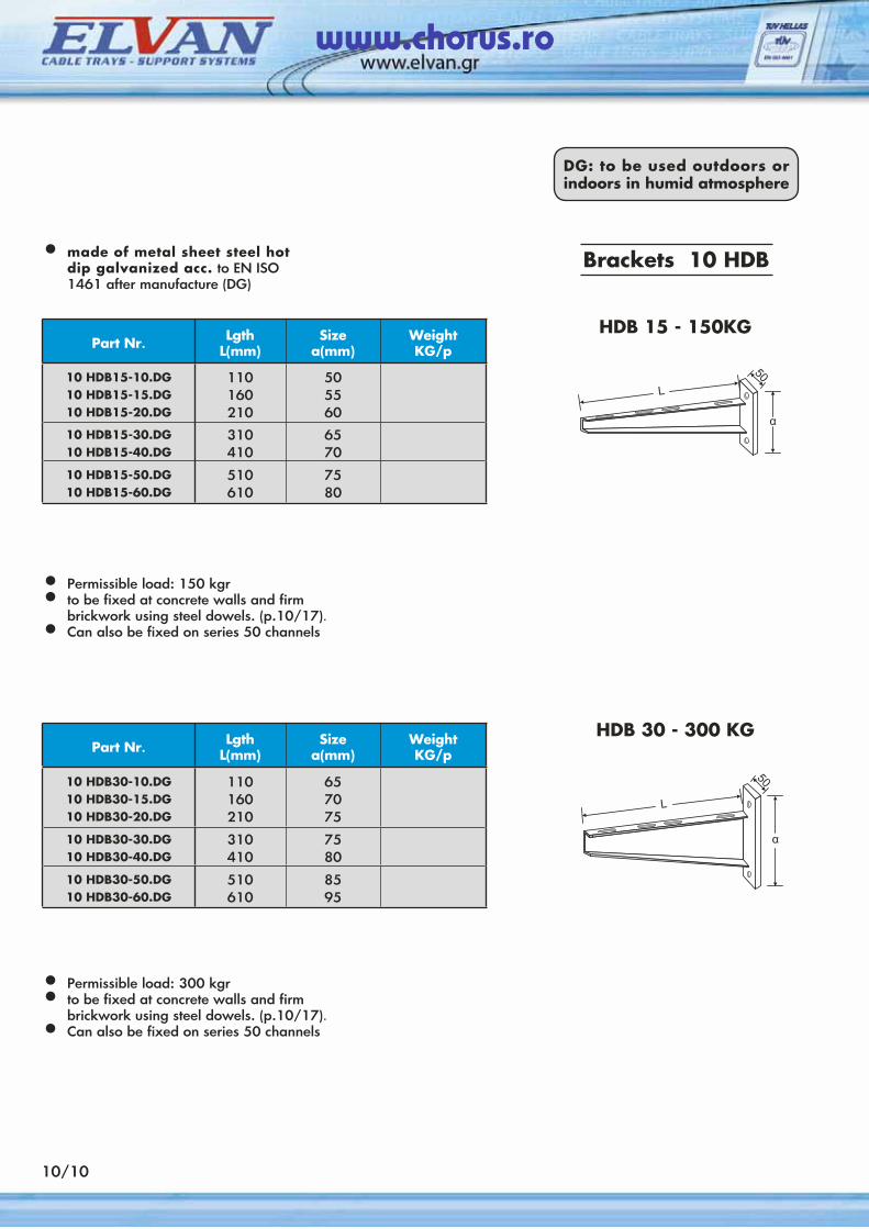
• made of metal sheet steel hot dip galvanized acc. to EN ISO 1461 after manufacture (DG)
Brackets 10 HDB
Part Nr. LgthL(mm)
Sizea(mm)
WeightKG/p
10 HDB15-10.DG10 HDB15-15.DG10 HDB15-20.DG
110160210
505560
10 HDB15-30.DG10 HDB15-40.DG
310410
6570
10 HDB15-50.DG10 HDB15-60.DG
510610
7580
• Permissible load: 150 kgr• to be fixed at concrete walls and firm
brickwork using steel dowels. (p.10/17).• Can also be fixed on series 50 channels
Part Nr. LgthL(mm)
Sizea(mm)
WeightKG/p
10 HDB30-10.DG10 HDB30-15.DG10 HDB30-20.DG
110160210
657075
10 HDB30-30.DG10 HDB30-40.DG
310410
7580
10 HDB30-50.DG10 HDB30-60.DG
510610
8595
• Permissible load: 300 kgr• to be fixed at concrete walls and firm
bric kwork using steel dowels. (p.10/17).• Can also be fixed on series 50 channels
10/10
HDB 15 - 150KG
HDB 30 - 300 KG
DG: to be used outdoors or indoors in humid atmosphere
www.chorus.ro
Part Nr. LgthL(mm)
Sizea(mm)
WeightKG/p
10 HDB50-20.DG10 HDB50-30.DG10 HDB50-40.DG
210310410
90110130
10 HDB50-50.DG10 HDB50-60.DG
510610
145170
10 HDB50-70.DG10 HDB50-80.DG
710810
200210
Part Nr. LgthL(mm)
Sizea(mm)
WeightKG/p
10 HDB80-20.DG10 HDB80-30.DG10 HDB80-40.DG
210310410
110145165
10 HDB80-50.DG10 HDB80-60.DG
510610
200220
10 HDB80-70.DG10 HDB80-80.DG
710810
240250
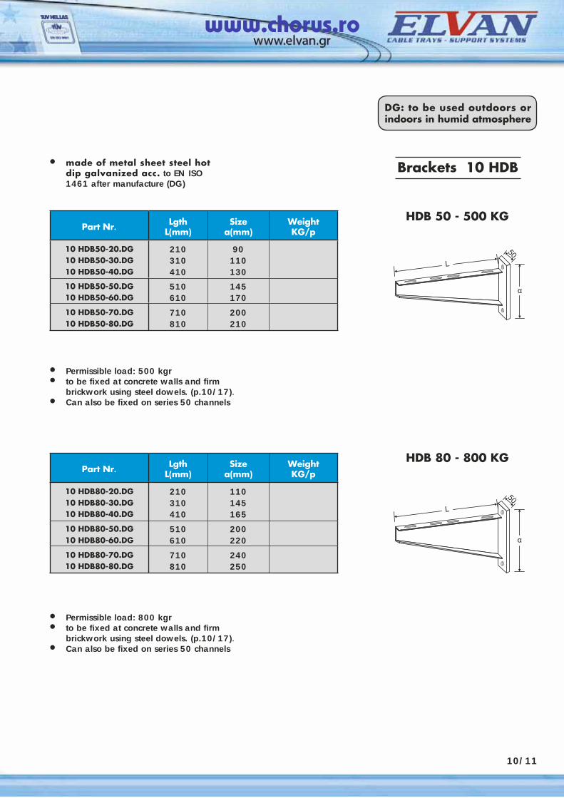
HDB 50 - 500 KG
HDB 80 - 800 KG
Brackets 10 ΗDB
10/11
DG: to be used outdoors or indoors in humid atmosphere
• made of metal sheet steel hot dip galvanized acc. to EN ISO 1461 after manufacture (DG)
• Permissible load: 500 kgr• to be fixed at concrete walls and firm
brickwork using steel dowels. (p.10/17).• Can also be fixed on series 50 channels
• Permissible load: 800 kgr• to be fixed at concrete walls and firm
bric kwork using steel dowels. (p.10/17).• Can also be fixed on series 50 channels
www.chorus.ro
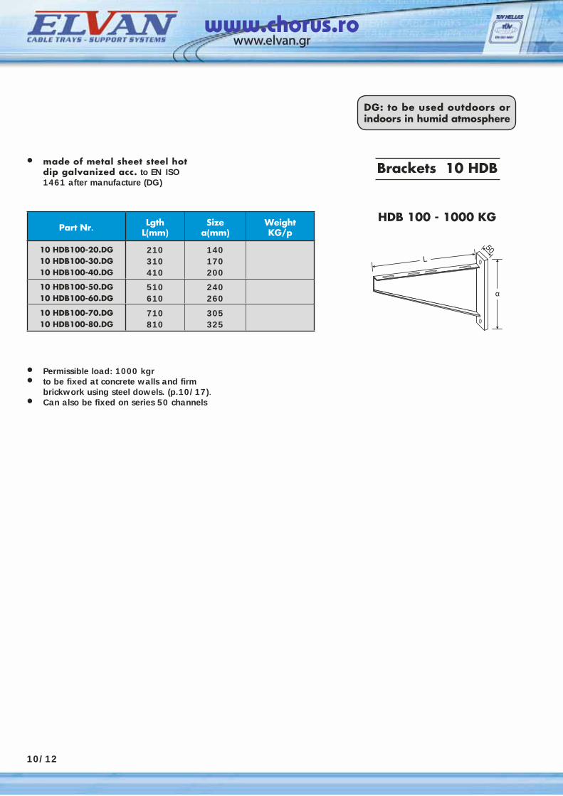
Part Nr. LgthL(mm)
Sizea(mm)
WeightKG/p
10 HDB100-20.DG10 HDB100-30.DG10 HDB100-40.DG
210310410
140170200
10 HDB100-50.DG10 HDB100-60.DG
510610
240260
10 HDB100-70.DG10 HDB100-80.DG
710810
305325
HDB 100 - 1000 KG
10/12
DG: to be used outdoors or indoors in humid atmosphere
• made of metal sheet steel hot dip galvanized acc. to EN ISO 1461 after manufacture (DG)
• Permissible load: 1000 kgr• to be fixed at concrete walls and firm
brickwork using steel dowels. (p.10/17).• Can also be fixed on series 50 channels
Brackets 10 ΗDB
www.chorus.ro
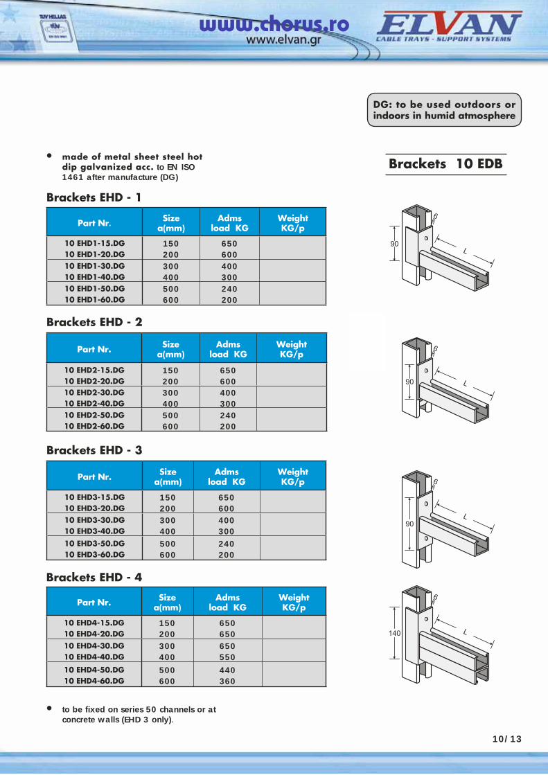
Brackets EHD - 1
Part Nr. Sizea(mm)
Admsload KG
WeightKG/p
10 ΕHD1-15.DG10 EHD1-20.DG
150200
650600
10 EHD1-30.DG10 EHD1-40.DG
300400
400300
10 EHD1-50.DG10 EHD1-60.DG
500600
240200
Brackets EHD - 2
Part Nr. Sizea(mm)
Admsload KG
WeightKG/p
10 ΕHD2-15.DG10 EHD2-20.DG
150200
650600
10 EHD2-30.DG10 EHD2-40.DG
300400
400300
10 EHD2-50.DG10 EHD2-60.DG
500600
240200
Brackets EHD - 3
Part Nr. Sizea(mm)
Admsload KG
WeightKG/p
10 ΕHD3-15.DG10 EHD3-20.DG
150200
650600
10 EHD3-30.DG10 EHD3-40.DG
300400
400300
10 EHD3-50.DG10 EHD3-60.DG
500600
240200
10/13
Brackets EHD - 4
Part Nr. Sizea(mm)
Admsload KG
WeightKG/p
10 ΕHD4-15.DG10 EHD4-20.DG
150200
650650
10 EHD4-30.DG10 EHD4-40.DG
300400
650550
10 EHD4-50.DG10 EHD4-60.DG
500600
440360
• to be fixed on series 50 channels or at concrete walls (EHD 3 only).
DG: to be used outdoors or indoors in humid atmosphere
Brackets 10 EDB• made of metal sheet steel hot dip galvanized acc. to EN ISO 1461 after manufacture (DG)
www.chorus.ro
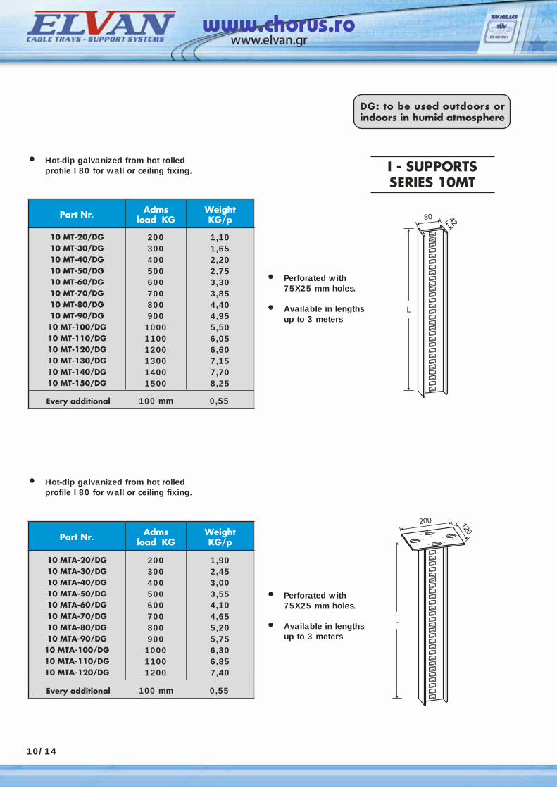
• Hot-dip galvanized from hot rolled profile I 80 for wall or ceiling fixing.
Part Nr. Admsload KG
WeightKG/p
10 MT-20/DG10 MT-30/DG10 MT-40/DG10 MT-50/DG10 MT-60/DG10 MT-70/DG10 MT-80/DG10 MT-90/DG10 MT-100/DG10 MT-110/DG10 MT-120/DG10 MT-130/DG10 MT-140/DG10 MT-150/DG
200300400500600700800900
100011001200130014001500
1,101,652,202,753,303,854,404,955,506,056,607,157,708,25
Every additional 100 mm 0,55
Part Nr. Admsload KG
WeightKG/p
10 MTA-20/DG10 MTA-30/DG10 MTA-40/DG10 MTA-50/DG10 MTA-60/DG10 MTA-70/DG10 MTA-80/DG10 MTA-90/DG10 MTA-100/DG10 MTA-110/DG10 MTA-120/DG
200300400500600700800900
100011001200
1,902,453,003,554,104,655,205,756,306,857,40
Every additional 100 mm 0,55
I - SUPPORTSSERIES 10MT
• Perforated with 75X25 mm holes.
• Available in lengths up to 3 meters
10/14
DG: to be used outdoors or indoors in humid atmosphere
• Hot-dip galvanized from hot rolled profile I 80 for wall or ceiling fixing.
• Perforated with 75X25 mm holes.
• Available in lengths up to 3 meters
www.chorus.ro
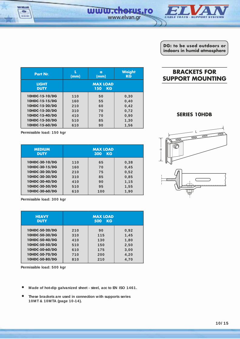
Part Nr. L(mm)
α(mm)
WeightKG
LIGHTDUTY
MAX LOAD150 KG
10HDC-15-10/DG10HDC-15-15/DG10HDC-15-20/DG10HDC-15-30/DG10HDC-15-40/DG10HDC-15-50/DG10HDC-15-60/DG
110160210310410510610
50556070708590
0,300,400,420,720,901,301,56
BRACKETS FOR SUPPORT MOUNTING
SERIES 10HDB
10/15
MEDIUMDUTY
MAX LOAD300 KG
10HDC-30-10/DG10HDC-30-15/DG10HDC-30-20/DG10HDC-30-30/DG10HDC-30-40/DG10HDC-30-50/DG10HDC-30-60/DG
110160210310410510610
657075859095100
0,380,450,520,851,151,551,90
HEAVYDUTY
MAX LOAD500 KG
10HDC-50-20/DG10HDC-50-30/DG10HDC-50-40/DG10HDC-50-50/DG10HDC-50-60/DG10HDC-50-70/DG10HDC-50-80/DG
210310410510610710810
90115130150175200210
0,921,451,802,503,004,204,70
Permissible load: 150 kgr
Permissible load: 300 kgr
Permissible load: 500 kgr
DG: to be used outdoors or indoors in humid atmosphere
• Made of hot-dip galvanized sheet - steel, acc to EN ISO 1461.
• These brackets are used in connection with supports series 10MT & 10MTA (page 10-14).
www.chorus.ro
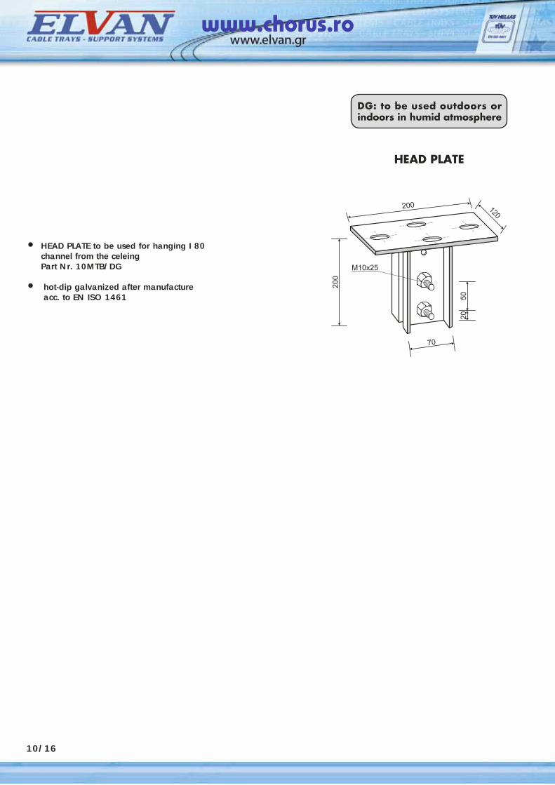
HEAD PLATE
• HEAD PLATE to be used for hanging I 80 channel from the celeing
Part Nr. 10MTB/DG
• hot-dip galvanized after manufacture acc. to EN ISO 1461
10/16
DG: to be used outdoors or indoors in humid atmosphere
www.chorus.ro
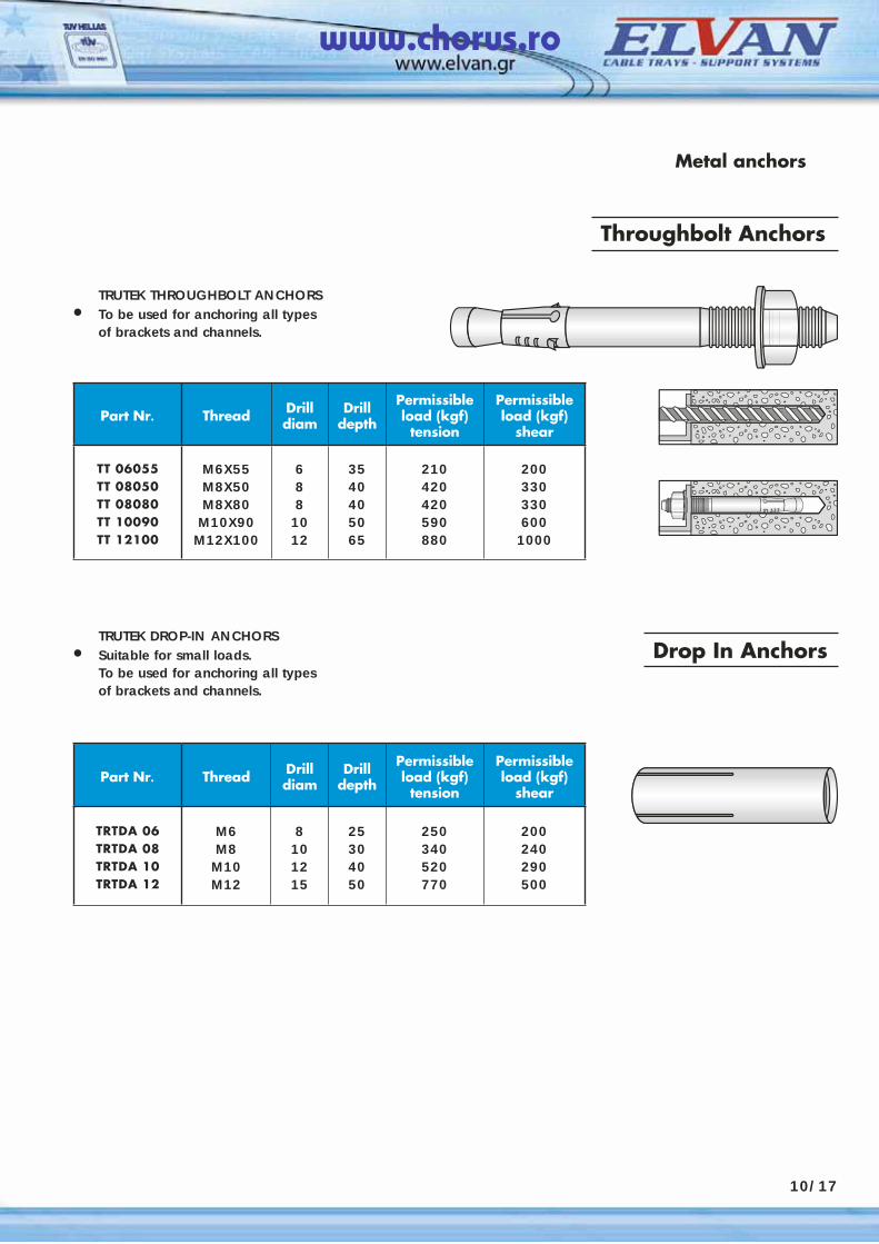
TRUTEK THROUGHBOLT ANCHORS• To be used for anchoring all types
of brackets and channels.
Part Nr. Thread Drilldiam
Drilldepth
Permissible load (kgf) tension
Permissible load (kgf)
shear
TT 06055TT 08050TT 08080TT 10090TT 12100
M6X55M8X50M8X80
M10X90M12X100
688
1012
3540405065
210420420590880
200330330600
1000
Throughbolt Anchors
Metal anchors
TRUTEK DROP-IN ANCHORS• Suitable for small loads. To be used for anchoring all types
of brackets and channels.
10/17
Drop In Anchors
Part Nr. Thread Drilldiam
Drilldepth
Permissible load (kgf) tension
Permissible load (kgf)
shear
TRTDA 06TRTDA 08TRTDA 10TRTDA 12
M6M8
M10M12
8101215
25304050
250340520770
200240290500
www.chorus.ro
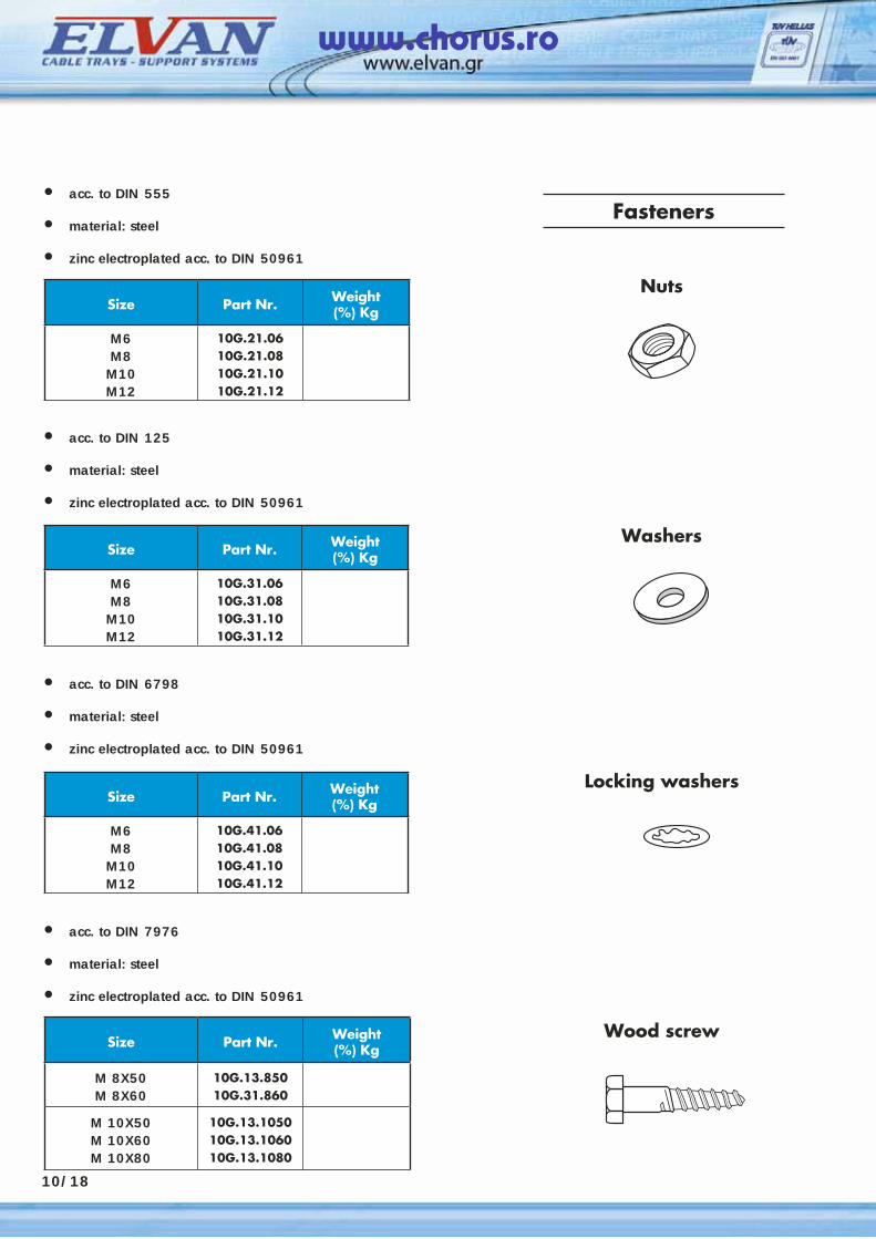
Fasteners• acc. to DIN 555
• material: steel
• zinc electroplated acc. to DIN 50961
Size Part Nr. Weight(%) Kg
M6M8
M10M12
10G.21.0610G.21.0810G.21.1010G.21.12
Size Part Nr. Weight(%) Kg
M6M8
M10M12
10G.31.0610G.31.0810G.31.1010G.31.12
Size Part Nr. Weight(%) Kg
M6M8
M10M12
10G.41.0610G.41.0810G.41.1010G.41.12
Size Part Nr. Weight(%) Kg
M 8X50M 8X60
10G.13.85010G.31.860
M 10X50M 10X60M 10X80
10G.13.105010G.13.106010G.13.1080
Nuts
Washers
Locking washers
Wood screw
10/18
• acc. to DIN 125
• material: steel
• zinc electroplated acc. to DIN 50961
• acc. to DIN 6798
• material: steel
• zinc electroplated acc. to DIN 50961
• acc. to DIN 7976
• material: steel
• zinc electroplated acc. to DIN 50961
www.chorus.ro
Fasteners
Size Part Nr. Weight(%) Kg
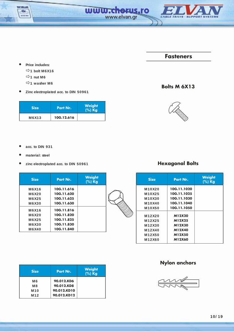
M6X13 10G.12.616
Bolts M 6X13
• Price includes:
1 bolt M6X16
1 nut M6
1 washer M6
• Zinc electroplated acc. to DIN 50961
Size Part Nr. Weight(%) Kg
M6X16M6X20M6X25M6X30
10G.11.61610G.11.62010G.11.62510G.11.630
M6X16M6X20M6X25M6X30M6X40
10G.11.81610G.11.82010G.11.82510G.11.83010G.11.840
• acc. to DIN 931
• material: steel
• zinc electroplated acc. to DIN 50961
Size Part Nr. Weight(%) Kg
M6M8
M10M12
90.012.KD690.012.KD8
90.012.KD1090.012.KD12
Size Part Nr. Weight(%) Kg
M10X20M10X25M10X30M10X40M10X50
10G.11.102010G.11.102510G.11.103010G.11.104010G.11.1050
M12X20M12X25M12X30M12X40M12X50M12X60
M12X20M12X25M12X30M12X40M12X50M12X60
Hexagonal Bolts
Nylon anchors
10/19
www.chorus.ro
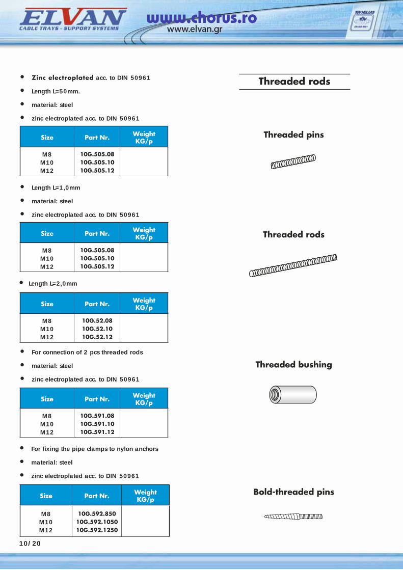
Threaded rods
Size Part Nr. Weight KG/p
M8M10M12
10G.505.0810G.505.1010G.505.12
Threaded pins
• Zinc electroplated acc. to DIN 50961 • Length L=50mm.
• material: steel
• zinc electroplated acc. to DIN 50961
Size Part Nr. Weight KG/p
M8M10M12
10G.505.0810G.505.1010G.505.12
• Length L=1,0mm
• material: steel
• zinc electroplated acc. to DIN 50961
Threaded rods
Size Part Nr. Weight KG/p
M8M10M12
10G.52.0810G.52.1010G.52.12
• Length L=2,0mm
Threaded bushing
Size Part Nr. Weight KG/p
M8M10M12
10G.591.0810G.591.1010G.591.12
• For connection of 2 pcs threaded rods
• material: steel
• zinc electroplated acc. to DIN 50961
Size Part Nr. Weight KG/p
M8M10M12
10G.592.85010G.592.105010G.592.1250
• For fixing the pipe clamps to nylon anchors
• material: steel • zinc electroplated acc. to DIN 50961
Bold-threaded pins
10/20
www.chorus.ro
63/01
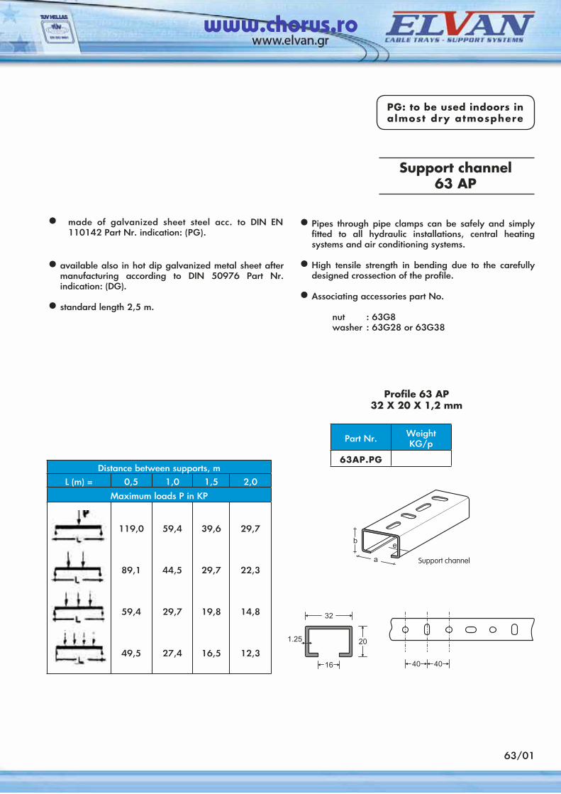
PG: to be used indoors in almost dry atmosphere
Support channel 63 AP
• made of galvanized sheet steel acc. to DIN EN 110142 Part Nr. indication: (PG).
• available also in hot dip galvanized metal sheet after manufacturing according to DIN 50976 Part Nr. indication: (DG).
• standard length 2,5 m.
• Pipes through pipe clamps can be safely and simply fitted to all hydraulic installations, central heating systems and air conditioning systems.
• High tensile strength in bending due to the carefully designed crossection of the profile.
• Associating accessories part No.
nut : 63G8washer : 63G28 or 63G38
Profile 63 AP32 Χ 20 Χ 1,2 mm
Part Nr. WeightKG/p
63AP.PGDistance between supports, m
L (m) = 0,5 1,0 1,5 2,0
Maximum loads Ρ in ΚΡ
119,0
89,1
59,4
49,5
59,4
44,5
29,7
27,4
39,6
29,7
19,8
16,5
29,7
22,3
14,8
12,3
www.chorus.ro
63/02
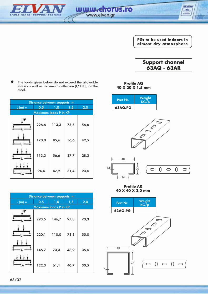
PG: to be used indoors in almost dry atmosphere
Support channel63AQ - 63AR
• The loads given below do not exceed the allowable stress as well as maximum deflection (L/150), on the steel.
Distance between supports, mL (m) = 0,5 1,0 1,5 2,0
Maximum loads Ρ in ΚΡ
226,6
170,0
113,3
94,4
113,3
85,6
56,6
47,2
75,5
56,6
37,7
31,4
56,6
42,5
28,3
23,6
Profile AQ40 Χ 20 Χ 1,5 mm
Part Nr. WeightKG/p
63AQ.PG
Distance between supports, m
L (m) = 0,5 1,0 1,5 2,0
Maximum loads Ρ in ΚΡ
293,5
220,1
146,7
122,3
146,7
110,0
73,3
61,1
97,8
73,3
48,9
40,7
73,3
55,0
36,6
30,5
Profile AR40 Χ 40 Χ 2.0 mm
Part Nr. WeightKG/p
63AQ.PG
www.chorus.ro

63/03
PG: to be used indoors in almost dry atmosphere
Support channel63AS - 63AT
• The loads given below do not exceed the allowable stress as well as maximum deflection (L/150), on the steel.
Distance between supports, mL (m) = 0,5 1,0 1,5 2,0
Maximum loads Ρ in ΚΡ
407,9
305,9
203,9
169,9
203,9
152,9
101,9
84,9
135,9
101,9
67,9
56,6
101,9
76,4
50,9
42,4
Profile 63 AS41 Χ 41 Χ 2,5 mm
Part Nr. WeightKG/p
63AS.PG
Distance between supports, mL (m) = 0,5 1,0 1,5 2,0
Maximum loads Ρ in ΚΡ
540,8
405,6
270,4
225,3
270,4
202,8
135,2
112,6
180,2
135,2
90,1
75,1
135,2
101,4
67,6
56,3
Profile 63 AT82 Χ 41 Χ 2,5 mm
Part Nr. WeightKG/p
63AT.PG
www.chorus.ro
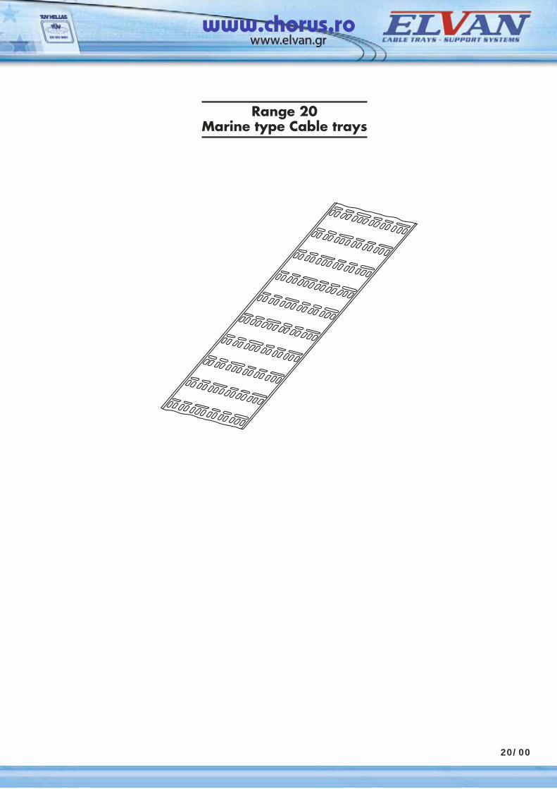
Range 20Marine type Cable trays
20/00
www.chorus.ro

www.chorus.ro
• Marine type cable trays standard perforation 20/02• Marine type cable trays full perforation 20/03• Perforated strips 20/04• Marine type perforated profiles 20/05
20/01
CONTENTS Ch. 20.MARINE TYPE CABLE TRAYS
www.chorus.ro

www.chorus.ro
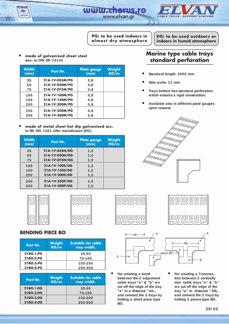
• made of galvanized sheet steel acc. to DIN EN 10142
Width(mm) Part Nr. Plate gauge
(mm)WeightKG/m
355075
21Α-1V-035M/PG21Α-1V-050M/PG21Α-1V-075M/PG
0,80,80,8
100150200
21Α-1V-100M/PG21Α-1V-150M/PG21Α-1V-200M/PG
0,80,80,8
250300
21Α-1V-250M/PG21Α-1V-300M/PG
0,80,8
• made of metal sheet hot dip galvanized acc. to EN ISO 1461 after manufacture (DG)
Width(mm) Part Nr. Plate gauge
(mm)WeightKG/m
355075
21Α-1V-035N/DG21Α-1V-050N/DG21Α-1V-075N/DG
1,01,01,0
100150200
21Α-1V-100S/DG21Α-1V-150S/DG21Α-1V-200S/DG
1,21,21,2
250300
21Α-1V-250P/DG21Α-1V-300P/DG
1,51,5
• Standard length: 3000 mm.
• Side walls: 12 mm.
• Trays bottom has standard perforation which ensures a rigid construction.
• Available also in different plate gauges upon request.
• For creating a bend between the 2 adjacment cable trays “a” & “b” we cut off the edge of the tray “a” in a distance ‘’ab,, and connect the 2 trays by bolting a small piece type BO.
• For creating a T-connec-tion between 2 vertically met cable trays “a” & “b” we cut off the edge of the tray “a” in distance ‘’AB,, and connect the 2 trays by bolting 2 pieces type BO.
20/02
Part Nr. WeightKG/m
Suitable for cable tray width.
21BO.1.PG21BO.2.PG
35-5075-100
21BO.3.PG21BO.4.PG
150-200250-300
Part Nr. WeightKG/m
Suitable for cable tray width.
21BO.1.DG21BO.2.DG
35-5075-100
21BO.3.DG21BO.4.DG
150-200250-300
BENDING PIECE BO
Marine type cable traysstandard perforation
PG: to be used indoors in almost dry atmosphere
DG: to be used outdoors or indoors in humid atmosphere
www.chorus.ro
Width(mm) Part Nr. Plate gauge
(mm)WeightKG/m
355075
21Α-1W-035M/PG21Α-1W-050M/PG21Α-1W-075M/PG
0,80,80,8
100150200
21Α-1W-100M/PG21Α-1W-150M/PG21Α-1W-200M/PG
0,80,80,8
250300
21Α-1W-250M/PG21Α-1W-300M/PG
0,80,8
Width(mm) Part Nr. Plate gauge
(mm)WeightKG/m
355075
21Α-1W-035N/DG21Α-1W-050N/DG21Α-1W-075N/DG
1,01,01,0
100150200
21Α-1W-100S/DG21Α-1W-150S/DG21Α-1W-200S/DG
1,21,21,2
250300
21Α-1W-250P/DG21Α-1W-300P/DG
1,51,5
Part Nr. WeightKG/m
Suitable for cable tray width.
21BO.1.PG21BO.2.PG
35-5075-100
21BO.3.PG21BO.4.PG
150-200250-300
Part Nr. WeightKG/m
Suitable for cable tray width.
21BO.1.DG21BO.2.DG
35-5075-100
21BO.3.DG21BO.4.DG
150-200250-300
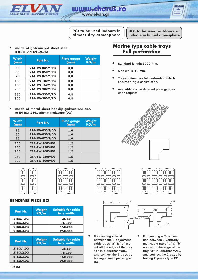
BENDING PIECE BO
20/03
Marine type cable traysFull perforation
PG: to be used indoors in almost dry atmosphere
DG: to be used outdoors or indoors in humid atmosphere
• made of galvanized sheet steel acc. to DIN EN 10142
• made of metal sheet hot dip galvanized acc. to EN ISO 1461 after manufacture (DG)
• Standard length: 3000 mm.
• Side walls: 12 mm.
• Trays bottom has Full perforation which ensures a rigid construction.
• Available also in different plate gauges upon request.
• For creating a bend between the 2 adjacment cable trays “a” & “b” we cut off the edge of the tray “a” in a distance ‘’ab,, and connect the 2 trays by bolting a small piece type BO.
• For creating a T-connec-tion between 2 vertically met cable trays “a” & “b” we cut off the edge of the tray “a” in distance ‘’AB,, and connect the 2 trays by bolting 2 pieces type BO.
www.chorus.ro
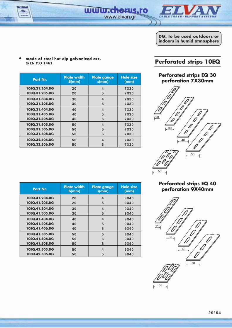
Perforated strips 10EQ
Part Nr. Plate width B(mm)
Plate gauge s(mm)
Hole size (mm)
10EQ.31.204.DG10EQ.31.205.DG
2020
45
7X307X30
10EQ.31.304.DG10EQ.31.305.DG
3030
45
7X307X30
10EQ.31.404.DG10EQ.31.405.DG10EQ.31.406.DG
404040
456
7X307X307X30
10EQ.31.505.DG10EQ.31.506.DG10EQ.31.508.DG
505050
456
7X307X307X30
10EQ.32.505.DG10EQ.32.506.DG
5050
45
7X307X30
Perforated strips EQ 30perforation 7X30mm
Perforated strips EQ 40perforation 9X40mmPart Nr. Plate width
B(mm)Plate gauge
s(mm)Hole size
(mm)
10EQ.41.204.DG10EQ.41.205.DG
2020
45
9X409X40
10EQ.41.304.DG10EQ.41.305.DG
3030
45
9X409X40
10EQ.41.404.DG10EQ.41.405.DG10EQ.41.406.DG
404040
456
9X409X409X40
10EQ.41.505.DG10EQ.41.506.DG10EQ.41.508.DG
505050
568
9X409X409X40
10EQ.42.505.DG10EQ.42.506.DG
5050
45
9X409X40
20/04
DG: to be used outdoors or indoors in humid atmosphere
• made of steel hot dip galvanized acc. to EN ISO 1461
www.chorus.ro
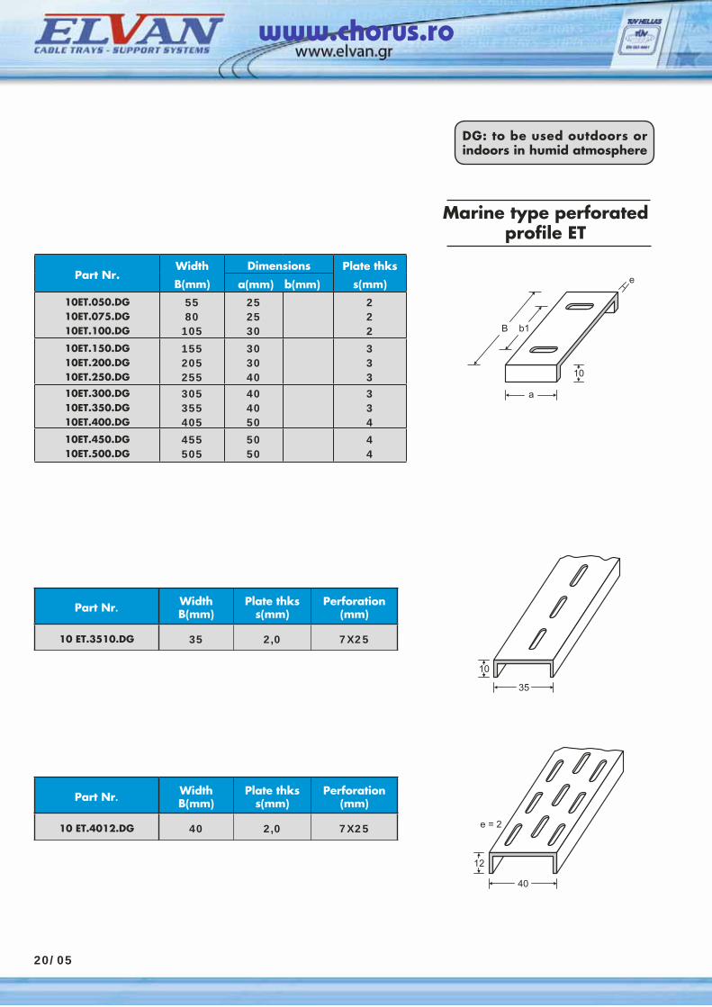
Marine type perforatedprofile ΕΤ
Part Nr.Width Dimensions Plate thks
Β(mm) a(mm) b(mm) s(mm)10ET.050.DG10ET.075.DG10ET.100.DG
5580
105
252530
222
10ET.150.DG10ET.200.DG10ET.250.DG
155205255
303040
333
10ET.300.DG10ET.350.DG10ET.400.DG
305355405
404050
334
10ET.450.DG10ET.500.DG
455505
5050
44
Part Nr. WidthB(mm)
Plate thkss(mm)
Perforation(mm)
10 ΕT.3510.DG 35 2,0 7X25
Part Nr. WidthB(mm)
Plate thkss(mm)
Perforation(mm)
10 ΕT.4012.DG 40 2,0 7X25
20/05
DG: to be used outdoors or indoors in humid atmosphere
www.chorus.ro
PG: to be used indoors in almost dry atmosphere
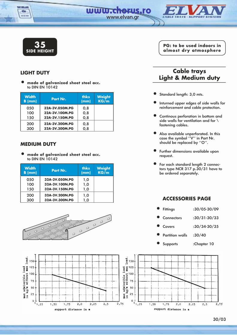
Cable traysLight & Medium duty
WidthΒ (mm) Part Nr. thks
(mm)WeightKG/m
050100150
32A-3V.050M.PG32A-3V.100M.PG32A-3V.150M.PG
0,80,80,8
200300
32A-3V.200M.PG32A-3V.300M.PG
0,80,8
• Standard length: 3,0 mts.
• Inturned upper edges of side walls for reinforcement and cable protection.
• Continous perforation in bottom and side walls for ventilation and for \ fastening cables.
• Also available unperforated. In this case the symbol ‘’V’’ in Part Nr. should be replaced by ‘’Ο’’.
• Further dimensions available upon request.
• For each standard length 2 connec-tors type NCR 317 p.30/31 have to be ordered separately.
LIGHT DUTY
WidthΒ (mm) Part Nr. thks
(mm)WeightKG/m
050100150
32A-3V.050N.PG32A-3V.100N.PG32A-3V.150N.PG
1,01,01,0
200300
32A-3V.200N.PG32A-3V.300N.PG
1,01,0
MEDIUM DUTY
30/03
ACCESSORIES PAGE • Fittings :30/05-30/09
• Connectors :30/31-30/33
• Covers :30/34-30/35
• Partition walls :30/40
• Supports :Chapter 10
• made of galvanized sheet steel acc. to DIN EN 10142
• made of galvanized sheet steel acc. to DIN EN 10142
35SIDE HEIGHT
www.chorus.ro
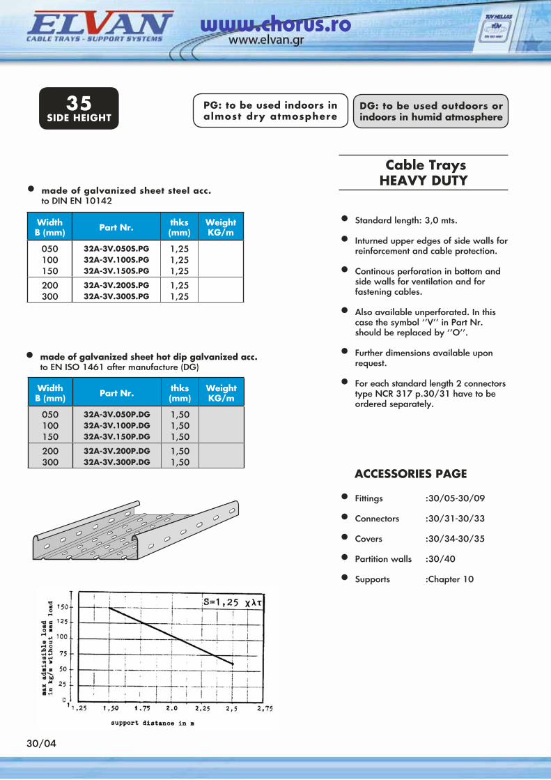
Cable TraysHEAVY DUTY
WidthΒ (mm) Part Nr. thks
(mm)WeightKG/m
050100150
32A-3V.050S.PG32A-3V.100S.PG32A-3V.150S.PG
1,251,251,25
200300
32A-3V.200S.PG32A-3V.300S.PG
1,251,25
WidthΒ (mm) Part Nr. thks
(mm)WeightKG/m
050100150
32A-3V.050P.DG32A-3V.100P.DG32A-3V.150P.DG
1,501,501,50
200300
32A-3V.200P.DG32A-3V.300P.DG
1,501,50
30/04
PG: to be used indoors in almost dry atmosphere
DG: to be used outdoors or indoors in humid atmosphere
35SIDE HEIGHT
• Standard length: 3,0 mts.
• Inturned upper edges of side walls for reinforcement and cable protection.
• Continous perforation in bottom and side walls for ventilation and for
fastening cables.
• Also available unperforated. In this case the symbol ‘’V’’ in Part Nr. should be replaced by ‘’Ο’’.
• Further dimensions available upon request.
• For each standard length 2 connectors type NCR 317 p.30/31 have to be ordered separately.
ACCESSORIES PAGE • Fittings :30/05-30/09
• Connectors :30/31-30/33
• Covers :30/34-30/35
• Partition walls :30/40
• Supports :Chapter 10
• made of galvanized sheet steel acc. to DIN EN 10142
• made of galvanized sheet hot dip galvanized acc. to EN ISO 1461 after manufacture (DG)
www.chorus.ro
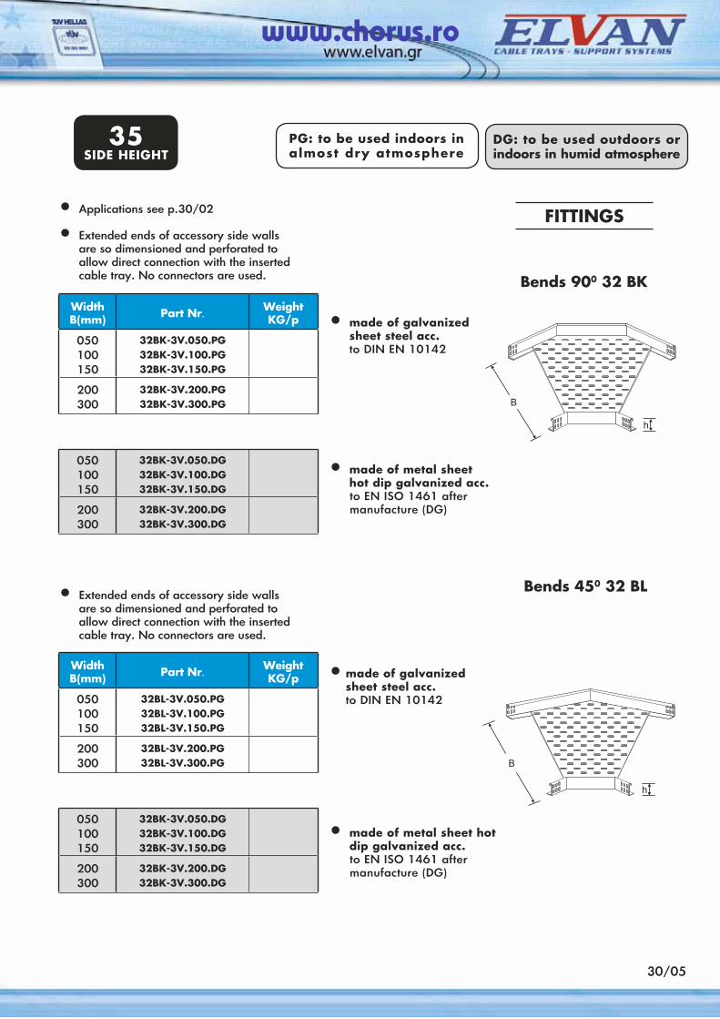
FITTINGS• Applications see p.30/02
• Extended ends of accessory side walls are so dimensioned and perforated to allow direct connection with the inserted cable tray. No connectors are used.
WidthΒ(mm) Part Nr. Weight
KG/p
050100150
32BK-3V.050.PG32BK-3V.100.PG32BK-3V.150.PG
200300
32BK-3V.200.PG32BK-3V.300.PG
• made of galvanized sheet steel acc.
to DIN EN 10142
050100150
32BK-3V.050.DG32BK-3V.100.DG32BK-3V.150.DG
200300
32BK-3V.200.DG32BK-3V.300.DG
• made of metal sheet hot dip galvanized acc. to EN ISO 1461 after
manufacture (DG)
• Extended ends of accessory side walls are so dimensioned and perforated to allow direct connection with the inserted cable tray. No connectors are used.
WidthΒ(mm) Part Nr. Weight
KG/p
050100150
32BL-3V.050.PG32BL-3V.100.PG32BL-3V.150.PG
200300
32BL-3V.200.PG32BL-3V.300.PG
• made of galvanized sheet steel acc.
to DIN EN 10142
050100150
32BK-3V.050.DG32BK-3V.100.DG32BK-3V.150.DG
200300
32BK-3V.200.DG32BK-3V.300.DG
• made of metal sheet hot dip galvanized acc.
to EN ISO 1461 after manufacture (DG)
Bends 450 32 BL
Bends 900 32 ΒΚ
30/05
PG: to be used indoors in almost dry atmosphere
DG: to be used outdoors or indoors in humid atmosphere
35SIDE HEIGHT
www.chorus.ro
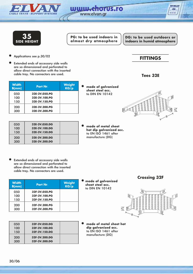
WidthΒ(mm) Part Nr. Weight
KG/p
050100150
32E-3V.050.PG32E-3V.100.PG32E-3V.150.PG
200300
32E-3V.200.PG32E-3V.300.PG
050100150
32E-3V.050.DG32E-3V.100.DG32E-3V.150.DG
200300
32E-3V.200.DG32E-3V.300.DG
WidthΒ(mm) Part Nr. Weight
KG/p
050100150
32F-3V.050.PG32F-3V.100.PG32F-3V.150.PG
200300
32F-3V.200.PG32F-3V.300.PG
050100150
32F-3V.050.DG32F-3V.100.DG32F-3V.150.DG
200300
32F-3V.200.DG32F-3V.300.DG
Crossing 32F
Tees 32E
30/06
PG: to be used indoors in almost dry atmosphere
DG: to be used outdoors or indoors in humid atmosphere
FITTINGS• Applications see p.30/02
• Extended ends of accessory side walls are so dimensioned and perforated to allow direct connection with the inserted cable tray. No connectors are used.
• Extended ends of accessory side walls are so dimensioned and perforated to allow direct connection with the inserted cable tray. No connectors are used.
35SIDE HEIGHT
• made of galvanized sheet steel acc.
to DIN EN 10142
• made of metal sheet hot dip galvanized acc. to EN ISO 1461 after
manufacture (DG)
• made of galvanized sheet steel acc.
to DIN EN 10142
• made of metal sheet hot dip galvanized acc.
to EN ISO 1461 after manufacture (DG)
www.chorus.ro
DG: to be used outdoors or indoors in humid atmosphere
30/07
PG: to be used indoors in almost dry atmosphere
35SIDE HEIGHT
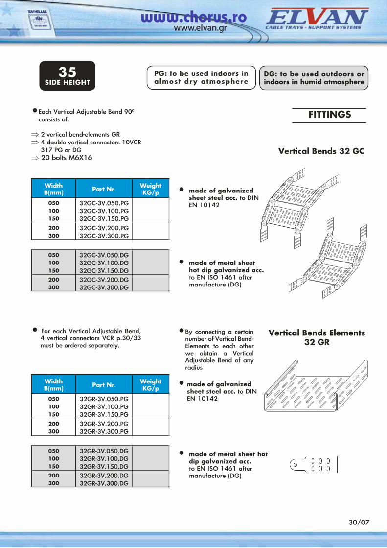
Vertical Bends Elements32 GR
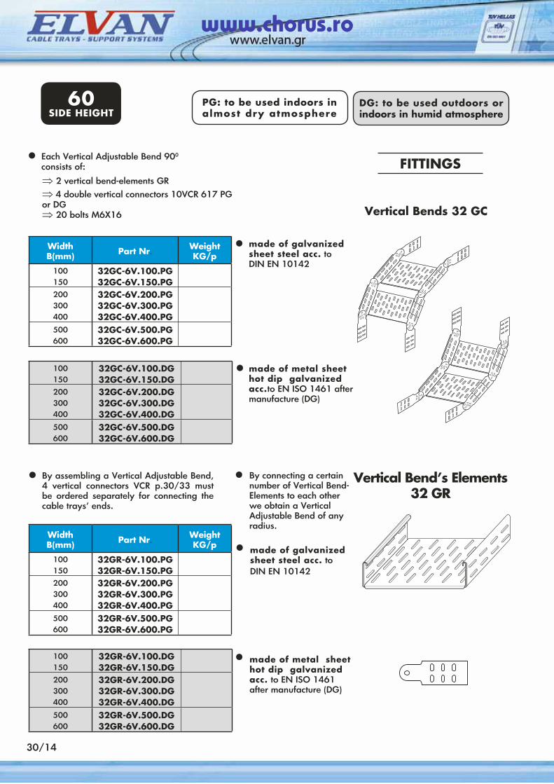
• Each Vertical Adjustable Bend 900 consists of:
⇒ 2 vertical bend-elements GR⇒ 4 double vertical connectors 10VCR
317 PG or DG⇒ 20 bolts M6X16
WidthΒ(mm) Part Nr. Weight
KG/p
050100150
32GC-3V.050.PG32GC-3V.100.PG32GC-3V.150.PG
200300
32GC-3V.200.PG32GC-3V.300.PG
050100150
32GC-3V.050.DG32GC-3V.100.DG32GC-3V.150.DG
200300
32GC-3V.200.DG32GC-3V.300.DG
Vertical Bends 32 GC
• For each Vertical Adjustable Bend, 4 vertical connectors VCR p.30/33 must be ordered separately.
WidthΒ(mm) Part Nr. Weight
KG/p
050100150
32GR-3V.050.PG32GR-3V.100.PG32GR-3V.150.PG
200300
32GR-3V.200.PG32GR-3V.300.PG
050100150
32GR-3V.050.DG32GR-3V.100.DG32GR-3V.150.DG
200300
32GR-3V.200.DG32GR-3V.300.DG
FITTINGS
• By connecting a certain number of Vertical Bend-Elements to each other we obtain a Vertical Adjustable Bend of any radius
• made of galvanized sheet steel acc. to DIN EN 10142
• made of metal sheet hot dip galvanized acc. to EN ISO 1461 after
manufacture (DG)
• made of galvanized sheet steel acc. to DIN EN 10142
• made of metal sheet hot dip galvanized acc.
to EN ISO 1461 after manufacture (DG)
www.chorus.ro
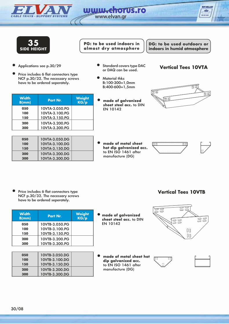
Vertical Tees 10VTB
WidthΒ(mm) Part Nr. Weight
KG/p
050100150
10VTA-3.050.PG10VTA-3.100.PG10VTA-3.150.PG
200300
10VTA-3.200.PG10VTA-3.300.PG
050100150
10VTA-3.050.DG10VTA-3.100.DG10VTA-3.150.DG
200300
10VTA-3.200.DG10VTA-3.300.DG
Vertical Tees 10VTA
30/08
WidthΒ(mm) Part Nr. Weight
KG/p
050100150
10VTB-3.050.PG10VTB-3.100.PG10VTB-3.150.PG
200300
10VTB-3.200.PG10VTB-3.300.PG
050100150
10VTB-3.050.DG10VTB-3.100.DG10VTB-3.150.DG
200300
10VTB-3.200.DG10VTB-3.300.DG
PG: to be used indoors in almost dry atmosphere
DG: to be used outdoors or indoors in humid atmosphere
• Applications see p.30/29
• Price includes 6 flat connectors type NCF p.30/32. The necessary screws have to be ordered seperately.
• Price includes 6 flat connectors type NCF p.30/32. The necessary screws have to be ordered seperately.
35SIDE HEIGHT
• Standard covers type DAC or DAQ can be used.
• Material thks B:100-300=1,0mm B:400-600=1,5mm
• made of galvanized sheet steel acc. to DIN EN 10142
• made of metal sheet hot dip galvanized acc. to EN ISO 1461 after
manufacture (DG)
• made of galvanized sheet steel acc. to DIN EN 10142
• made of metal sheet hot dip galvanized acc.
to EN ISO 1461 after manufacture (DG)
www.chorus.ro
Applications
WidthΒ(mm) Part Nr. Weight
KG/p
050100150
10RA-3.050.PG10RA-3.100.PG10RA-3.150.PG
200300400
10RA-3.200.PG10RA-3.300.PG10RA-3.400.PG
500600
10RA-3.500.PG10RA-3.600.PG
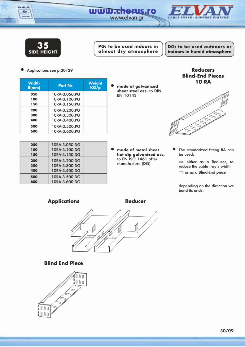
ReducersBlind-End Pieces
10 RA
050100150
10RA-3.050.DG10RA-3.100.DG10RA-3.150.DG
200300400
10RA-3.200.DG10RA-3.300.DG10RA-3.400.DG
500600
10RA-3.500.DG10RA-3.600.DG
• The standarized fitting RA can be used:
⇒ either as a Reducer, to reduce the cable tray’s width
⇒ or as a Blind-End piece
depending on the direction we bend its ends.
Reducer
Blind End Piece
30/09
• Applications see p.30/29
• made of galvanized sheet steel acc. to DIN EN 10142
• made of metal sheet hot dip galvanized acc. to EN ISO 1461 after
manufacture (DG)
PG: to be used indoors in almost dry atmosphere
DG: to be used outdoors or indoors in humid atmosphere
35SIDE HEIGHT
www.chorus.ro
PG: to be used indoors in almost dry atmosphere
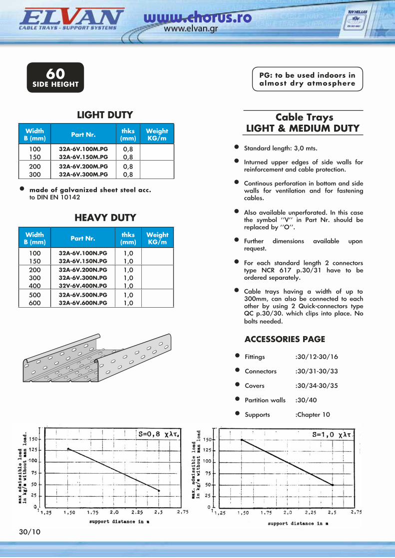
• Standard length: 3,0 mts.
• Inturned upper edges of side walls for reinforcement and cable protection.
• Continous perforation in bottom and side walls for ventilation and for fastening cables.
• Also available unperforated. In this case the symbol ‘’V’’ in Part Nr. should be replaced by ‘’Ο’’.
• Further dimensions available upon request.
• For each standard length 2 connectors type NCR 617 p.30/31 have to be ordered separately.
• Cable trays having a width of up to 300mm, can also be connected to each other by using 2 Quick-connectors type QC p.30/30. which clips into place. No bolts needed.
Cable TraysLIGHT & MEDIUM DUTYWidth
Β (mm) Part Nr. thks(mm)
WeightKG/m
100150
32A-6V.100M.PG32A-6V.150M.PG
0,80,8
200300
32A-6V.200M.PG32A-6V.300M.PG
0,80,8
WidthΒ (mm) Part Nr. thks
(mm)WeightKG/m
100150
32A-6V.100N.PG32A-6V.150N.PG
1,01,0
200300400
32A-6V.200N.PG32A-6V.300N.PG32V-6V.400N.PG
1,01,01,0
500600
32A-6V.500N.PG32A-6V.600N.PG
1,01,0
LIGHT DUTY
HEAVY DUTY
30/10
ACCESSORIES PAGE • Fittings :30/12-30/16
• Connectors :30/31-30/33
• Covers :30/34-30/35
• Partition walls :30/40
• Supports :Chapter 10
• made of galvanized sheet steel acc. to DIN EN 10142
60SIDE HEIGHT
www.chorus.ro
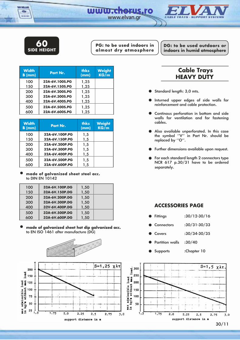
Standard length: 3,0 mts.
Inturned upper edges of side walls for reinforcement and cable protection.
Continous perforation in bottom and side walls for ventilation and for fastening cables.
Also available unperforated. In this case the symbol ‘’V’’ in Part Nr. should be replaced by ‘’Ο’’.
Further dimensions available upon request.
For each standard length 2 connectors type NCR 617 p.30/31 have to be ordered separately.
Cable TraysHEAVY DUTY
WidthΒ (mm) Part Nr. thks
(mm)WeightKG/m
100150
32A-6V.100S.PG32A-6V.150S.PG
1,251,25
200300400
32A-6V.200S.PG32A-6V.300S.PG32A-6V.400S.PG
1,251,251,25
500600
32A-6V.500S.PG32A-6V.600S.PG
1,251,25
100150
32A-6V.100P.DG32A-6V.150P.DG
1,501,50
200300400
32A-6V.200P.DG32A-6V.300P.DG32V-6V.400P.DG
1,501,501,50
500600
32A-6V.500P.DG32A-6V.600P.DG
1,501,50
••
•
•
••
ACCESSORIES PAGE Fittings :30/12-30/16
Connectors :30/31-30/33
Covers :30/34-30/35
Partition walls :30/40
Supports :Chapter 10
•••••
WidthΒ (mm) Part Nr. thks
(mm)WeightKG/m
100150
32A-6V.100P.PG32A-6V.150P.PG
1,51,5
200300400
32A-6V.200P.PG32A-6V.300P.PG32A-6V.400P.PG
1,51,51,5
500600
32A-6V.500P.PG32A-6V.600P.PG
1,51,5
30/11
• made of galvanized sheet steel acc. to DIN EN 10142
• made of galvanized sheet hot dip galvanized acc. to EN ISO 1461 after manufacture (DG)
PG: to be used indoors in almost dry atmosphere
DG: to be used outdoors or indoors in humid atmosphere
60SIDE HEIGHT
www.chorus.ro
30/12
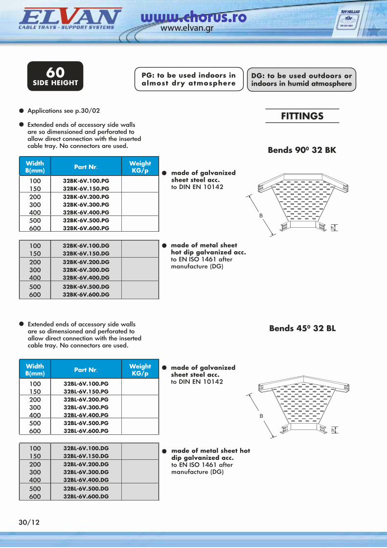
Applications see p.30/02
Extended ends of accessory side walls are so dimensioned and perforated to allow direct connection with the inserted cable tray. No connectors are used.
WidthΒ(mm) Part Nr. Weight
KG/p
100150
32BK-6V.100.PG32BK-6V.150.PG
200300400
32BK-6V.200.PG32BK-6V.300.PG32BK-6V.400.PG
500600
32BK-6V.500.PG32BK-6V.600.PG
• made of galvanized sheet steel acc.to DIN EN 10142
••
100150
32BK-6V.100.DG32BK-6V.150.DG
200300400
32BK-6V.200.DG32BK-6V.300.DG32BK-6V.400.DG
500600
32BK-6V.500.DG32BK-6V.600.DG
• made of metal sheethot dip galvanized acc.to EN ISO 1461 after manufacture (DG)
Extended ends of accessory side walls are so dimensioned and perforated to allow direct connection with the inserted cable tray. No connectors are used.
WidthΒ(mm) Part Nr. Weight
KG/p
100150
32BL-6V.100.PG32BL-6V.150.PG
200300400
32BL-6V.200.PG32BL-6V.300.PG32BL-6V.400.PG
500600
32BL-6V.500.PG32BL-6V.600.PG
• made of galvanized sheet steel acc.to DIN EN 10142
•
100150
32BL-6V.100.DG32BL-6V.150.DG
200300400
32BL-6V.200.DG32BL-6V.300.DG32BL-6V.400.DG
500600
32BL-6V.500.DG32BL-6V.600.DG
• made of metal sheet hot dip galvanized acc.to EN ISO 1461 after manufacture (DG)
Bends 450 32 BL
Bends 900 32 ΒΚ
FITTINGS
60SIDE HEIGHT
PG: to be used indoors in almost dry atmosphere
DG: to be used outdoors or indoors in humid atmosphere
www.chorus.ro
30/13
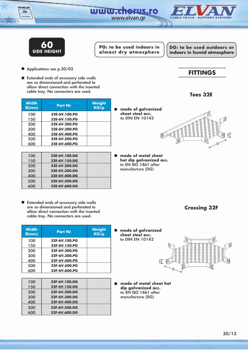
Applications see p.30/02
Extended ends of accessory side walls are so dimensioned and perforated to allow direct connection with the inserted cable tray. No connectors are used.
WidthΒ(mm) Part Nr. Weight
KG/p
100150
32E-6V.100.PG32E-6V.150.PG
200300400
32E-6V.200.PG32E-6V.300.PG32E-6V.400.PG
500600
32E-6V.500.PG32E-6V.600.PG
• made of galvanized sheet steel acc.to DIN EN 10142
••
100150
32E-6V.100.DG32E-6V.150.DG
200300400
32E-6V.200.DG32E-6V.300.DG32E-6V.400.DG
500600
32E-6V.500.DG32E-6V.600.DG
• made of metal sheethot dip galvanized acc.to EN ISO 1461 after manufacture (DG)
Extended ends of accessory side walls are so dimensioned and perforated to allow direct connection with the inserted cable tray. No connectors are used.
WidthΒ(mm) Part Nr. Weight
KG/p
100150
32F-6V.100.PG32F-6V.150.PG
200300400
32F-6V.200.PG32F-6V.300.PG32F-6V.400.PG
500600
32F-6V.500.PG32F-6V.600.PG
• made of galvanized sheet steel acc.to DIN EN 10142
•
100150
32F-6V.100.DG32F-6V.150.DG
200300400
32F-6V.200.DG32F-6V.300.DG32F-6V.400.DG
500600
32F-6V.500.DG32F-6V.600.DG
•
Crossing 32F
Tees 32E
made of metal sheet hot dip galvanized acc.to EN ISO 1461 after manufacture (DG)
FITTINGS
60SIDE HEIGHT
PG: to be used indoors in almost dry atmosphere
DG: to be used outdoors or indoors in humid atmosphere
www.chorus.ro
100150
32GC-6V.100.DG32GC-6V.150.DG
200300400
32GC-6V.200.DG32GC-6V.300.DG32GC-6V.400.DG
500600
32GC-6V.500.DG32GC-6V.600.DG
WidthΒ(mm) Part Nr. Weight
KG/p
100150
32GC-6V.100.PG32GC-6V.150.PG
200300400
32GC-6V.200.PG32GC-6V.300.PG32GC-6V.400.PG
500600
32GC-6V.500.PG32GC-6V.600.PG
Each Vertical Adjustable Bend 900 consists of:
•
made of galvanized sheet steel acc. to DIN EN 10142
•
made of metal sheet hot dip galvanized acc.to EN ISO 1461 aftermanufacture (DG)
•
By connecting a certain number of Vertical Bend-Elements to each other we obtain a Vertical Adjustable Bend of any radius.
•By assembling a Vertical Adjustable Bend, 4 vertical connectors VCR p.30/33 must be ordered separately for connecting the cable trays’ ends.
⇒ 2 vertical bend-elements GR⇒ 4 double vertical connectors 10VCR 617 PG or DG⇒ 20 bolts M6X16
100150
32GR-6V.100.DG32GR-6V.150.DG
200300400
32GR-6V.200.DG32GR-6V.300.DG32GR-6V.400.DG
500600
32GR-6V.500.DG32GR-6V.600.DG
WidthΒ(mm) Part Nr. Weight
KG/p
100150
32GR-6V.100.PG32GR-6V.150.PG
200300400
32GR-6V.200.PG32GR-6V.300.PG32GR-6V.400.PG
500600
32GR-6V.500.PG32GR-6V.600.PG
made of galvanized sheet steel acc. to DIN EN 10142
•
made of metal sheethot dip galvanizedacc. to EN ISO 1461after manufacture (DG)
•
Vertical Bend’s Elements 32 GR
30/14
Vertical Bends 32 GC
•
FITTINGS
60SIDE HEIGHT
PG: to be used indoors in almost dry atmosphere
DG: to be used outdoors or indoors in humid atmosphere
www.chorus.ro
30/15
Price includes 6 flat connectorstype NCF p.30/32. Bolts have to be ordered separately.
•
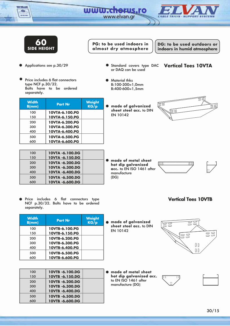
Vertical Tees 10VTAApplications see p.30/29 •
•
•
100150
10VTA -6.100.DG10VTA -6.150.DG
200300400
10VTA -6.200.DG10VTA -6.300.DG10VTA -6.400.DG
500600
10VTA -6.500.DG10VTA -6.600.DG
WidthΒ(mm) Part Nr. Weight
KG/p
100150
10VTA-6.100.PG10VTA-6.150.PG
200300400
10VTA-6.200.PG10VTA-6.300.PG10VTA-6.400.PG
500600
10VTA-6.500.PG10VTA-6.600.PG
100150
10VTB -6.100.DG10VTB -6.150.DG
200300400
10VTB -6.200.DG10VTB -6.300.DG10VTB -6.400.DG
500600
10VTB -6.500.DG10VTB -6.600.DG
WidthΒ(mm) Part Nr. Weight
KG/p
100150
10VTB-6.100.PG10VTB-6.150.PG
200300400
10VTB-6.200.PG10VTB-6.300.PG10VTB-6.400.PG
500600
10VTB-6.500.PG10VTB-6.600.PG
•
•
Price includes 6 flat connectors type NCF p.30/32. Bolts have to be ordered separately.
• Vertical Tees 10VTB
•
•
PG: to be used indoors in almost dry atmosphere
60SIDE HEIGHT
DG: to be used outdoors or indoors in humid atmosphere
Standard covers type DAC or DAQ can be used
Material thksB:100-300=1,0mmB:400-600=1,5mm
made of galvanized sheet steel acc. to DIN EN 10142
made of metal sheet hot dip galvanized acc. to EN ISO 1461 after manufacture(DG)
made of galvanizedsheet steel acc. to DINEN 10142
made of metal sheet hot dip galvanized acc.to EN ISO 1461 after manufacture (DG)
www.chorus.ro
30/16
WidthΒ(mm) Part Nr. Weight
KG/p
100150
10RA-6.100.PG10RA-6.150.PG
200300400
10RA-6.200.PG10RA-6.300.PG10RA-6.400.PG
500600
10RA-6.500.PG10RA-6.600.PG
100150
10RA-6.100.DG10RA-6.150.DG
200300400
10RA-6.200.DG10RA-6.300.DG10RA-6.400.DG
500600
10RA-6.500.DG10RA-6.600.DG
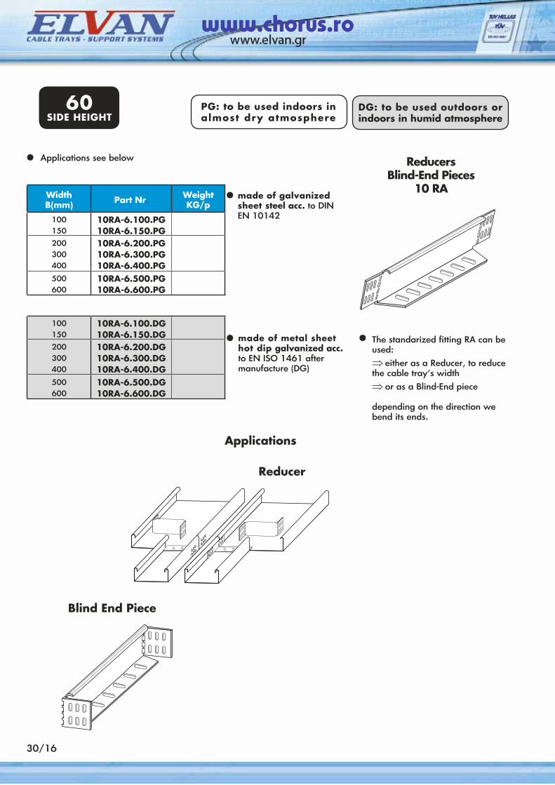
• ReducersBlind-End Pieces
10 RA
Applications
Reducer
Blind End Piece
Applications see below
made of metal sheet hot dip galvanized acc. to EN ISO 1461 after manufacture (DG)
made of galvanized sheet steel acc. to DINEN 10142
The standarized fitting RA can be used:⇒ either as a Reducer, to reduce the cable tray’s width⇒ or as a Blind-End piece
depending on the direction we bend its ends.
•
• •
60SIDE HEIGHT
PG: to be used indoors in almost dry atmosphere
DG: to be used outdoors or indoors in humid atmosphere
www.chorus.ro
• made of galvanized sheet steel acc.to DIN EN 10142
made of metal sheet hot dip galvanizedacc. to EN ISO 1461 after manufacture (DG)
•
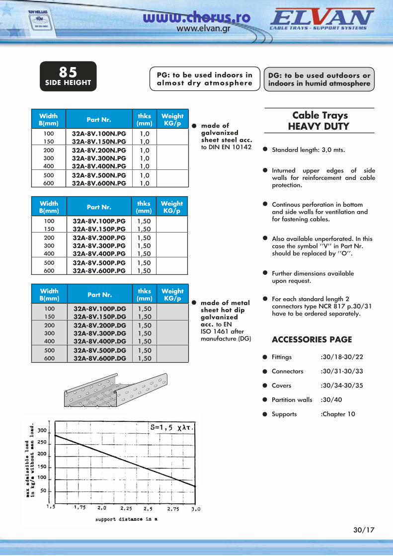
Standard length: 3,0 mts.•Inturned upper edges of side walls for reinforcement and cable protection.
•
Continous perforation in bottom and side walls for ventilation and for fastening cables.
•
Also available unperforated. In thiscase the symbol ‘’V’’ in Part Nr.should be replaced by ‘’Ο’’.
•
Further dimensions available upon request.
•
For each standard length 2 connectors type NCR 817 p.30/31have to be ordered separately.
•
WidthΒ(mm) Part Nr. thks
(mm)Weight KG/p
100150
32A-8V.100P.PG32A-8V.150P.PG
1,501,50
200300400
32A-8V.200P.PG32A-8V.300P.PG32A-8V.400P.PG
1,501,501,50
500600
32A-8V.500P.PG32A-8V.600P.PG
1,501,50
WidthΒ(mm) Part Nr. thks
(mm)Weight KG/p
100150
32A-8V.100P.DG32A-8V.150P.DG
1,501,50
200300400
32A-8V.200P.DG32A-8V.300P.DG32A-8V.400P.DG
1,501,501,50
500600
32A-8V.500P.DG32A-8V.600P.DG
1,501,50
30/17
Cable TraysHEAVY DUTY
ACCESSORIES PAGE Fittings :30/18-30/22
Connectors :30/31-30/33
Covers :30/34-30/35
Partition walls :30/40
Supports :Chapter 10
•••••
WidthΒ(mm) Part Nr. thks
(mm)Weight KG/p
100150
32A-8V.100N.PG32A-8V.150N.PG
1,01,0
200300400
32A-8V.200N.PG32A-8V.300N.PG32A-8V.400N.PG
1,01,01,0
500600
32A-8V.500N.PG32A-8V.600N.PG
1,01,0
PG: to be used indoors in almost dry atmosphere
DG: to be used outdoors or indoors in humid atmosphere
85SIDE HEIGHT
www.chorus.ro
Applications see p.30/02
WidthΒ(mm) Part Nr. Weight
KG/p
100150
32BK-8V.100.PG32BK-8V.150.PG
200300400
32BK-8V.200.PG32BK-8V.300.PG32BK-8V.400.PG
500600
32BK-8V.500.PG32BK-8V.600.PG
100150
32BK-8V.100.DG32BK-8V.150.DG
200300400
32BK-8V.200.DG32BK-8V.300.DG32BK-8V.400.DG
500600
32BK-8V.500.DG32BK-8V.600.DG
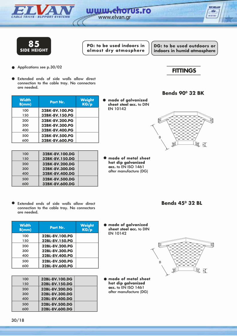
Extended ends of side walls allow direct connection to the cable tray. No connectors are needed.
• made of galvanized sheet steel acc. to DINEN 10142
• made of metal sheet hot dip galvanized acc. to EN ISO 1461 after manufacture (DG)
Extended ends of side walls allow direct connection to the cable tray. No connectors are needed.
WidthΒ(mm) Part Nr. Weight
KG/p
100150
32BL-8V.100.PG32BL-8V.150.PG
200300400
32BL-8V.200.PG32BL-8V.300.PG32BL-8V.400.PG
500600
32BL-8V.500.PG32BL-8V.600.PG
100150
32BL-8V.100.DG32BL-8V.150.DG
200300400
32BL-8V.200.DG32BL-8V.300.DG32BL-8V.400.DG
500600
32BL-8V.500.DG32BL-8V.600.DG
•
•made of galvanized sheet steel acc. to DINEN 10142
•made of metal sheet hot dip galvanized acc. to EN ISO 1461 after manufacture (DG)
30/18
PG: to be used indoors in almost dry atmosphere
FITTINGS
Bends 900 32 ΒΚ
Bends 450 32 BL
•
•
85SIDE HEIGHT
DG: to be used outdoors or indoors in humid atmosphere
www.chorus.ro
30/19
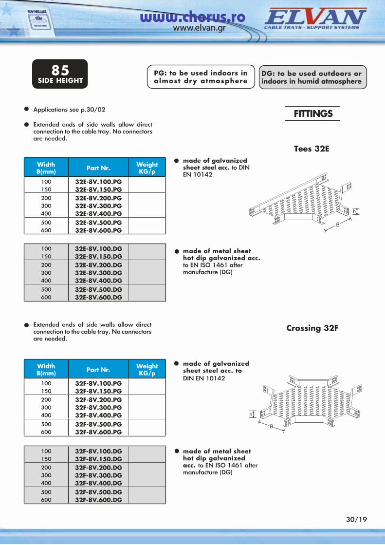
Applications see p.30/02•
100150
32E-8V.100.DG32E-8V.150.DG
200300400
32E-8V.200.DG32E-8V.300.DG32E-8V.400.DG
500600
32E-8V.500.DG32E-8V.600.DG
WidthΒ(mm) Part Nr. Weight
KG/p
100150
32E-8V.100.PG32E-8V.150.PG
200300400
32E-8V.200.PG32E-8V.300.PG32E-8V.400.PG
500600
32E-8V.500.PG32E-8V.600.PG
made of galvanized sheet steel acc. to DINEN 10142
made of metal sheethot dip galvanized acc.to EN ISO 1461 aftermanufacture (DG)
•
•
Extended ends of side walls allow direct connection to the cable tray. No connectors are needed.
Extended ends of side walls allow direct connection to the cable tray. No connectors are needed.
100150
32F-8V.100.DG32F-8V.150.DG
200300400
32F-8V.200.DG32F-8V.300.DG32F-8V.400.DG
500600
32F-8V.500.DG32F-8V.600.DG
WidthΒ(mm) Part Nr. Weight
KG/p
100150
32F-8V.100.PG32F-8V.150.PG
200300400
32F-8V.200.PG32F-8V.300.PG32F-8V.400.PG
500600
32F-8V.500.PG32F-8V.600.PG
made of galvanized sheet steel acc. toDIN EN 10142
made of metal sheethot dip galvanized acc. to EN ISO 1461 aftermanufacture (DG)
•
•
85SIDE HEIGHT
PG: to be used indoors in almost dry atmosphere
DG: to be used outdoors or indoors in humid atmosphere
FITTINGS
Crossing 32F
Tees 32E
85SIDE HEIGHT
DG: to be used outdoors or indoors in humid atmosphere
•
•
www.chorus.ro
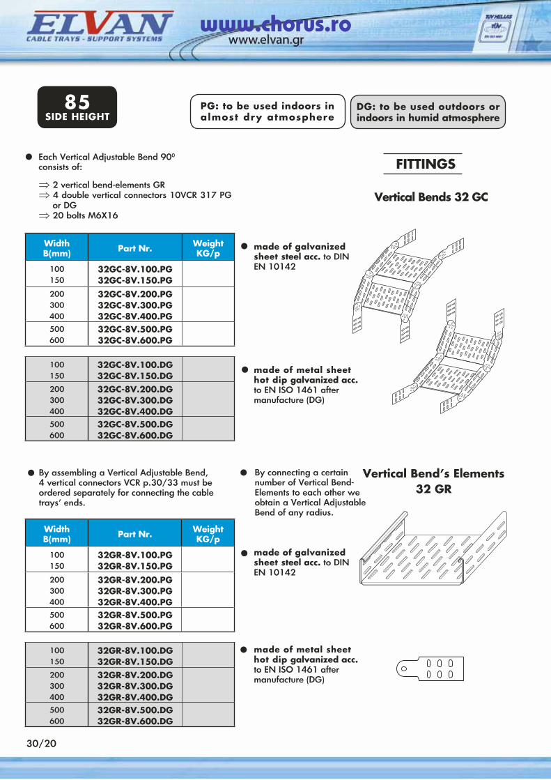
Each Vertical Adjustable Bend 900 consists of:
•⇒ 2 vertical bend-elements GR⇒ 4 double vertical connectors 10VCR 317 PG
or DG⇒ 20 bolts M6X16
• made of galvanized sheet steel acc. to DINEN 10142
• made of metal sheet hot dip galvanized acc.to EN ISO 1461 after manufacture (DG)
Vertical Bends 32 GC
By connecting a certain number of Vertical Bend-Elements to each other we obtain a Vertical Adjustable Bend of any radius.
•By assembling a Vertical Adjustable Bend, 4 vertical connectors VCR p.30/33 must be ordered separately for connecting the cable trays’ ends.
•
30/20
• made of galvanized sheet steel acc. to DINEN 10142
• made of metal sheet hot dip galvanized acc.to EN ISO 1461 after manufacture (DG)
100150
32GC-8V.100.DG32GC-8V.150.DG
200300400
32GC-8V.200.DG32GC-8V.300.DG32GC-8V.400.DG
500600
32GC-8V.500.DG32GC-8V.600.DG
WidthΒ(mm) Part Nr. Weight
KG/p
100150
32GC-8V.100.PG32GC-8V.150.PG
200300400
32GC-8V.200.PG32GC-8V.300.PG32GC-8V.400.PG
500600
32GC-8V.500.PG32GC-8V.600.PG
100150
32GR-8V.100.DG32GR-8V.150.DG
200300400
32GR-8V.200.DG32GR-8V.300.DG32GR-8V.400.DG
500600
32GR-8V.500.DG32GR-8V.600.DG
WidthΒ(mm) Part Nr. Weight
KG/p
100150
32GR-8V.100.PG32GR-8V.150.PG
200300400
32GR-8V.200.PG32GR-8V.300.PG32GR-8V.400.PG
500600
32GR-8V.500.PG32GR-8V.600.PG
FITTINGS
Vertical Bend’s Elements32 GR
85SIDE HEIGHT
PG: to be used indoors in almost dry atmosphere
DG: to be used outdoors or indoors in humid atmosphere
www.chorus.ro
85SIDE HEIGHT
30/21
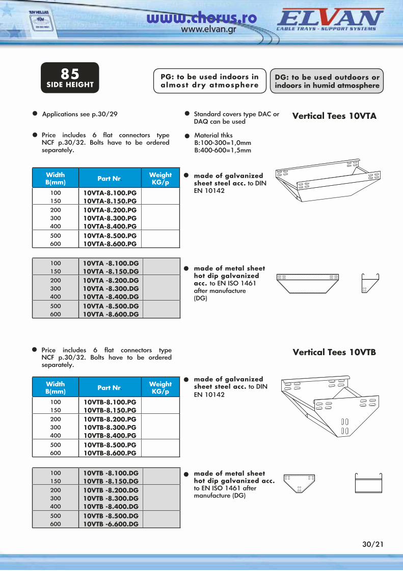
Price includes 6 flat connectors type NCF p.30/32. Bolts have to be ordered separately.
•
Vertical Tees 10VTAApplications see p.30/29 Standard covers type DAC or DAQ can be used
•Material thksB:100-300=1,0mmB:400-600=1,5mm
•
•
100150
10VTA -8.100.DG10VTA -8.150.DG
200300400
10VTA -8.200.DG10VTA -8.300.DG10VTA -8.400.DG
500600
10VTA -8.500.DG10VTA -8.600.DG
WidthΒ(mm) Part Nr. Weight
KG/p
100150
10VTA-8.100.PG10VTA-8.150.PG
200300400
10VTA-8.200.PG10VTA-8.300.PG10VTA-8.400.PG
500600
10VTA-8.500.PG10VTA-8.600.PG
100150
10VTB -8.100.DG10VTB -8.150.DG
200300400
10VTB -8.200.DG10VTB -8.300.DG10VTB -8.400.DG
500600
10VTB -8.500.DG10VTB -6.600.DG
WidthΒ(mm) Part Nr. Weight
KG/p
100150
10VTB-8.100.PG10VTB-8.150.PG
200300400
10VTB-8.200.PG10VTB-8.300.PG10VTB-8.400.PG
500600
10VTB-8.500.PG10VTB-8.600.PG
made of galvanized sheet steel acc. to DIN EN 10142
•
made of metal sheet hot dip galvanized acc. to EN ISO 1461 after manufacture(DG)
•
• Price includes 6 flat connectors type NCF p.30/32. Bolts have to be ordered separately.
•
•
Vertical Tees 10VTB
made of galvanizedsheet steel acc. to DINEN 10142
made of metal sheet hot dip galvanized acc.to EN ISO 1461 after manufacture (DG)
DG: to be used outdoors or indoors in humid atmosphere
PG: to be used indoors in almost dry atmosphere
www.chorus.ro
WidthΒ(mm) Part Nr. Weight
KG/p
100150
10RA-8.100.PG10RA-8.150.PG
200300400
10RA-8.200.PG10RA-8.300.PG10RA-8.400.PG
500600
10RA-8.500.PG10RA-8.600.PG
100150
10RA-8.100.DG10RA-8.150.DG
200300400
10RA-8.200.DG10RA-8.300.DG10RA-8.400.DG
500600
10RA-8.500.DG10RA-8.600.DG
Applications
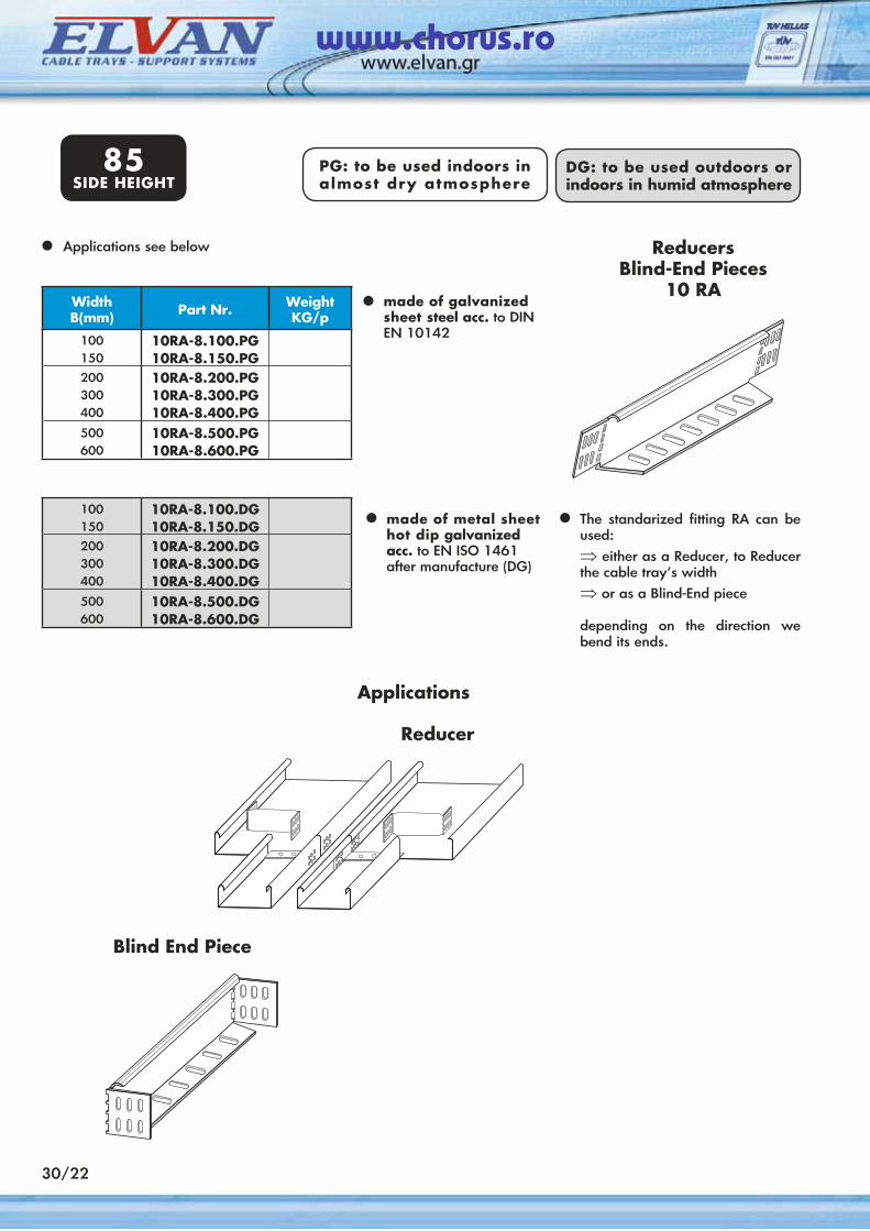
Applications see below•
•
•
ReducersBlind-End Pieces
10 RAmade of galvanized sheet steel acc. to DINEN 10142
made of metal sheet hot dip galvanized acc. to EN ISO 1461 after manufacture (DG)
• The standarized fitting RA can be used:⇒ either as a Reducer, to Reducer the cable tray’s width⇒ or as a Blind-End piece
depending on the direction we bend its ends.
Reducer
Blind End Piece
85SIDE HEIGHT
PG: to be used indoors in almost dry atmosphere
30/22
DG: to be used outdoors or indoors in humid atmosphere
www.chorus.ro
DG: to be used outdoors or indoors in humid atmosphere
30/23
110SIDE HEIGHT
DG: to be used outdoors or indoors in humid atmosphere
PG: to be used indoors in almost dry atmosphere
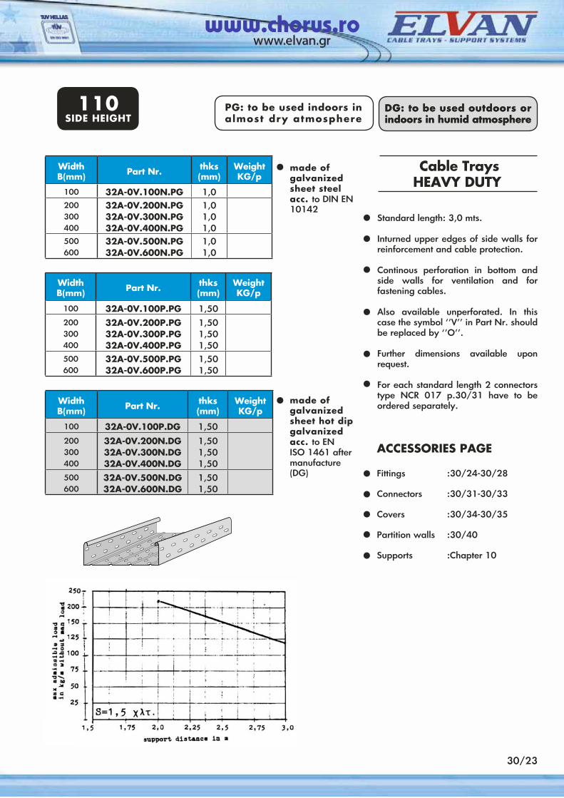
Standard length: 3,0 mts.
Inturned upper edges of side walls for reinforcement and cable protection.
Continous perforation in bottom and side walls for ventilation and for fastening cables.
Also available unperforated. In this case the symbol ‘’V’’ in Part Nr. should be replaced by ‘’Ο’’.
Further dimensions available upon request.
For each standard length 2 connectors type NCR 017 p.30/31 have to be ordered separately.
Cable TraysHEAVY DUTY
••
•
•
•
•
ACCESSORIES PAGE Fittings :30/24-30/28
Connectors :30/31-30/33
Covers :30/34-30/35
Partition walls :30/40
Supports :Chapter 10
•••••
WidthΒ(mm) Part Nr. thks
(mm)Weight KG/p
100 32A-0V.100P.PG 1,50200300400
32A-0V.200P.PG32A-0V.300P.PG32A-0V.400P.PG
1,501,501,50
500600
32A-0V.500P.PG32A-0V.600P.PG
1,501,50
WidthΒ(mm) Part Nr. thks
(mm)Weight KG/p
100 32A-0V.100P.DG 1,50200300400
32A-0V.200N.DG32A-0V.300N.DG32A-0V.400N.DG
1,501,501,50
500600
32A-0V.500N.DG32A-0V.600N.DG
1,501,50
made of galvanized sheet steel acc. to DIN EN 10142
•
made of galvanized sheet hot dip galvanized acc. to EN ISO 1461 after manufacture (DG)
•
WidthΒ(mm) Part Nr. thks
(mm)Weight KG/p
100 32A-0V.100N.PG 1,0200300400
32A-0V.200N.PG32A-0V.300N.PG32A-0V.400N.PG
1,01,01,0
500600
32A-0V.500N.PG32A-0V.600N.PG
1,01,0
www.chorus.ro
110SIDE HEIGHT
WidthΒ(mm) Part Nr. Weight
KG/p
100 32BK-0V.100.PG200300400
32BK-0V.200.PG32BK-0V.300.PG32BK-0V.400.PG
500600
32BK-0V.500.PG32BK-0V.600.PG
100 32BK-0V.100.DG200300400
32BK-0V.200.DG32BK-0V.300.DG32BK-0V.400.DG
500600
32BK-0V.500.DG32BK-0V.600.DG
WidthΒ(mm) Part Nr. Weight
KG/p
100 32BL-0V.100.PG200300400
32BL-0V.200.PG32BL-0V.300.PG32BL-0V.400.PG
500600
32BL-0V.500.PG32BL-0V.600.PG
100 32BL-0V.100.DG200300400
32BL-0V.200.DG32BL-0V.300.DG32BL-0V.400.DG
500600
32BL-0V.500.DG32BL-0V.600.DG
30/24
PG: to be used indoors in almost dry atmosphere
DG: to be used outdoors or indoors in humid atmosphere
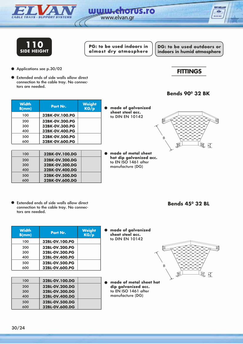
FITTINGSApplications see p.30/02
Extended ends of side walls allow direct connection to the cable tray. No connec-tors are needed.
• made of galvanized sheet steel acc.to DIN EN 10142
••
• made of metal sheethot dip galvanized acc.to EN ISO 1461 after manufacture (DG)
Extended ends of side walls allow direct connection to the cable tray. No connec-tors are needed.
• made of galvanized sheet steel acc.to DIN EN 10142
•
• made of metal sheet hot dip galvanized acc.to EN ISO 1461 after manufacture (DG)
Bends 450 32 BL
Bends 900 32 ΒΚ
www.chorus.ro
WidthΒ(mm) Part Nr. Weight
KG/p
100 32E-0V.100.PG200300400
32E-0V.200.PG32E-0V.300.PG32E-0V.400.PG
500600
32E-0V.500.PG32E-0V.600.PG
100 32E-0V.100.DG200300400
32E-0V.200.DG32E-0V.300.DG32E-0V.400.DG
500600
32E-0V.500.DG32E-0V.600.DG
WidthΒ(mm) Part Nr. Weight
KG/p
100 32F-0V.100.PG200300400
32F-0V.200.PG32F-0V.300.PG32F-0V.400.PG
500600
32F-0V.500.PG32F-0V.600.PG
100 32F-0V.100.DG200300400
32F-0V.200.DG32F-0V.300.DG32F-0V.400.DG
500600
32F-0V.500.DG32F-0V.600.DG
30/25
110SIDE HEIGHT
PG: to be used indoors in almost dry atmosphere
DG: to be used outdoors or indoors in humid atmosphere
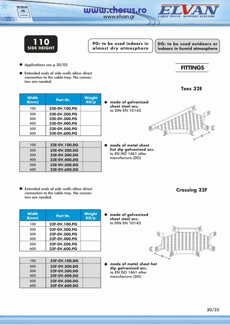
FITTINGSApplications see p.30/02
Extended ends of side walls allow direct connection to the cable tray. No connec-tors are needed.
•
••
•
Extended ends of side walls allow direct connection to the cable tray. No connec-tors are needed.
•
•
•
Crossing 32F
Tees 32E
made of galvanized sheet steel acc.to DIN EN 10142
made of metal sheethot dip galvanized acc.to EN ISO 1461 after manufacture (DG)
made of galvanized sheet steel acc.to DIN EN 10142
made of metal sheet hot dip galvanized acc.to EN ISO 1461 after manufacture (DG)
www.chorus.ro
30/26
110SIDE HEIGHT
100 32GC-0V.100.DG200300400
32GC-0V.200.DG32GC-0V.300.DG32GC-0V.400.DG
500600
32GC-0V.500.DG32GC-0V.600.DG
WidthΒ(mm) Part Nr. Weight
KG/p
100 32GC-0V.100.PG200300400
32GC-0V.200.PG32GC-0V.300.PG32GC-0V.400.PG
500600
32GC-0V.500.PG32GC-0V.600.PG
100 32GR-0V.100.DG200300400
32GR-0V.200.DG32GR-0V.300.DG32GR-0V.400.DG
500600
32GR-0V.500.DG32GR-0V.600.DG
WidthΒ(mm) Part Nr. Weight
KG/p
100 32GR-0V.100.PG200300400
32GR-0V.200.PG32GR-0V.300.PG32GR-0V.400.PG
500600
32GR-0V.500.PG32GR-0V.600.PG
PG: to be used indoors in almost dry atmosphere
DG: to be used outdoors or indoors in humid atmosphere
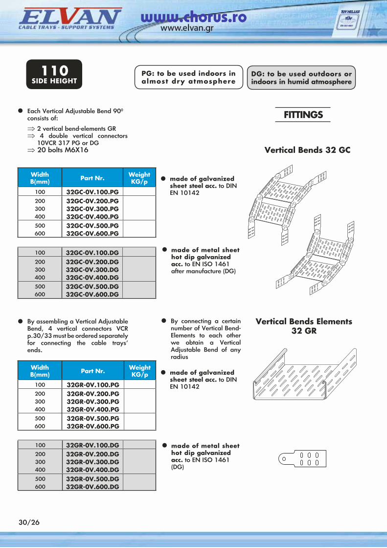
Vertical Bends Elements32 GR
Each Vertical Adjustable Bend 900 consists of:
⇒ 2 vertical bend-elements GR⇒ 4 double vertical connectors
10VCR 317 PG or DG⇒ 20 bolts M6X16
•
•
•
FITTINGS
Vertical Bends 32 GC
By assembling a Vertical Adjustable Bend, 4 vertical connectors VCR p.30/33 must be ordered separately for connecting the cable trays’ ends.
•
• made of galvanized sheet steel acc. to DINEN 10142
made of metal sheet hot dip galvanized acc. to EN ISO 1461 (DG)
•
made of galvanized sheet steel acc. to DINEN 10142
made of metal sheet hot dip galvanized acc. to EN ISO 1461 after manufacture (DG)
By connecting a certain number of Vertical Bend-Elements to each other we obtain a Vertical Adjustable Bend of any radius
•
www.chorus.ro
110SIDE HEIGHT
30/27
100 10VTA-0.100.DG200300400
10VTA-0.200.DG10VTA-0.300.DG10VTA-0.400.DG
500600
10VTA-0.500.DG10VTA-0.600.DG
WidthΒ(mm) Part Nr. Weight
KG/p
100 10VTA-0.100.PG200300400
10VTA-0.200.PG10VTA-0.300.PG10VTA-0.400.PG
500600
10VTA-0.500.PG10VTA-0.600.PG
100 10VTB-0.100.DG200300400
10VTB-0.200.DG10VTB-0.300.DG10VTB-0.400.DG
500600
10VTB-0.500.DG10VTB-0.600.DG
WidthΒ(mm) Part Nr. Weight
KG/p
100 10VTB-0.100.PG200300400
10VTB-0.200.PG10VTB-0.300.PG10VTB-0.400.PG
500600
10VTB-0.500.PG10VTB-0.600.PG
DG: to be used outdoors or indoors in humid atmosphere
PG: to be used indoors in almost dry atmosphere
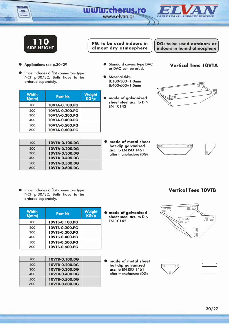
Vertical Tees 10VTB
Applications see p.30/29
Price includes 6 flat connectors type NCF p.30/32. Bolts have to be ordered separately.
•
•
•
Vertical Tees 10VTA
Price includes 6 flat connectors type NCF p.30/32. Bolts have to be ordered separately.
•
made of galvanized sheet steel acc. to DINEN 10142
made of metal sheet hot dip galvanized acc. to EN ISO 1461 after manufacture (DG)
•
made of galvanized sheet steel acc. to DINEN 10142
made of metal sheet hot dip galvanized acc. to EN ISO 1461 after manufacture (DG)
•• Standard covers type DAC
or DAQ can be used.
Material thksB:100-300=1,0mmB:400-600=1,5mm
•
•
www.chorus.ro
WidthΒ(mm) Part Nr. Weight
KG/p
100 10RA-0.100.PG200300400
10RA-0.200.PG10RA-0.300.PG10RA-0.400.PG
500600
10RA-0.500.PG10RA-0.600.PG
100 10RA-0.100.DG200300400
10RA-0.200.DG10RA-0.300.DG10RA-0.400.DG
500600
10RA-0.500.DG10RA-0.600.DG
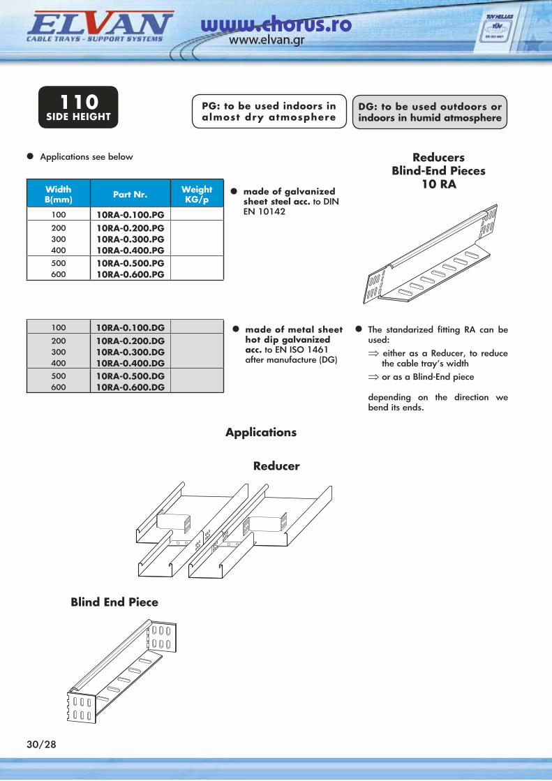
Applications
Applications see below•
•
•
ReducersBlind-End Pieces
10 RAmade of galvanized sheet steel acc. to DINEN 10142
made of metal sheet hot dip galvanized acc. to EN ISO 1461 after manufacture (DG)
• The standarized fitting RA can be used:⇒ either as a Reducer, to reduce
the cable tray’s width⇒ or as a Blind-End piece
depending on the direction we bend its ends.
Reducer
Blind End Piece
110SIDE HEIGHT
30/28
PG: to be used indoors in almost dry atmosphere
DG: to be used outdoors or indoors in humid atmosphere
www.chorus.ro
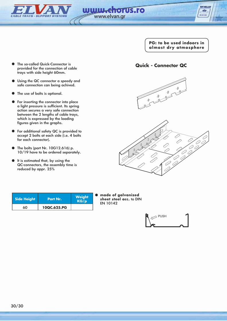
The so-called Quick-Connector is provided for the connection of cable trays with side height 60mm.
Using the QC connector a speedy and safe connection can being achived.
The use of bolts is optional.
For inserting the connector into place a light pressure is sufficient. Its spring action secures a very safe connection between the 2 lengths of cable trays, which is expressed by the loading figures given in the graphs.
For additional safety QC is provided to accept 2 bolts at each side (i.e. 4 bolts for each connector).
The bolts (part Nr. 10G12.616) p. 10/19 have to be ordered separately.
It is estimated that, by using the QC-connectors, the assembly time is reduced by appr. 25%
•
•
••
•
•
•
Quick - Connector QC
Side Height Part Nr. Weight KG/p
60 10QC.625.PG
made of galvanizedsheet steel acc. to DINEN 10142
•
30/30
PG: to be used indoors in almost dry atmosphere
www.chorus.ro
30/31
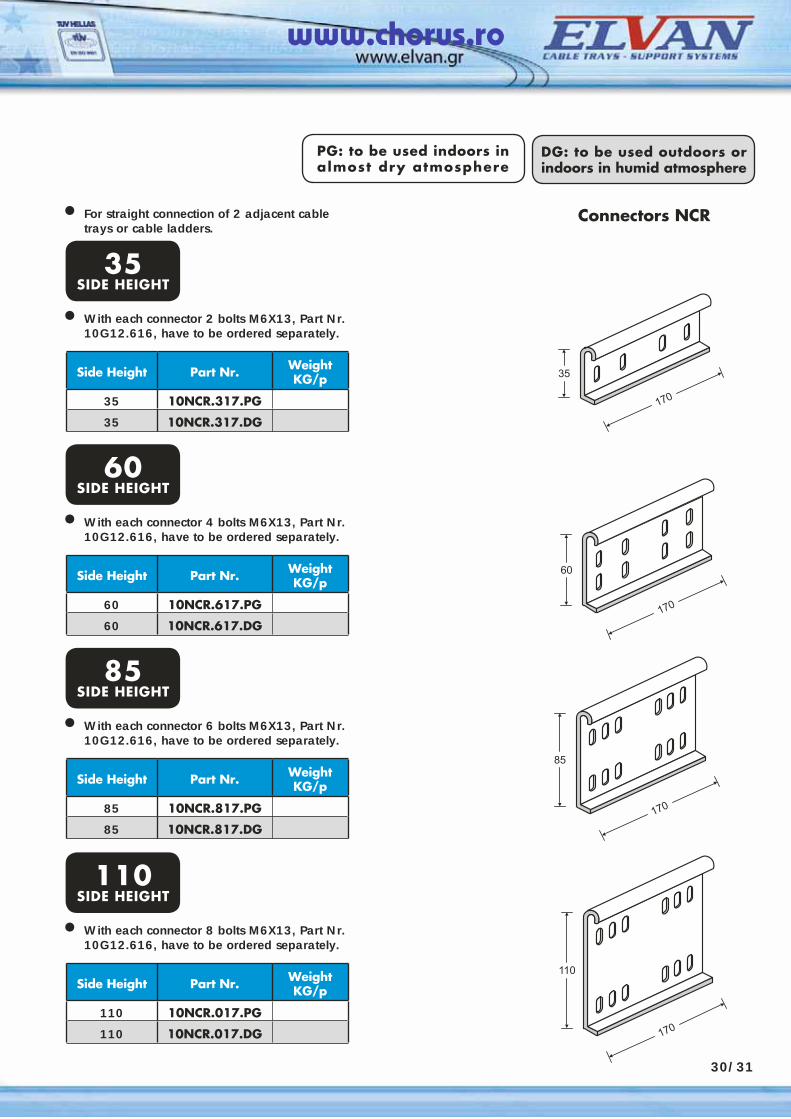
For straight connection of 2 adjacent cable trays or cable ladders.
• Connectors NCR
Side Height Part Nr. Weight KG/p
35 10NCR.317.PG
35 10NCR.317.DG
PG: to be used indoors in almost dry atmosphere
DG: to be used outdoors or indoors in humid atmosphere
35SIDE HEIGHT
With each connector 2 bolts M6X13, Part Nr. 10G12.616, have to be ordered separately.
•
Side Height Part Nr. Weight KG/p
60 10NCR.617.PG
60 10NCR.617.DG
60SIDE HEIGHT
With each connector 4 bolts M6X13, Part Nr. 10G12.616, have to be ordered separately.
•
Side Height Part Nr. Weight KG/p
85 10NCR.817.PG
85 10NCR.817.DG
85SIDE HEIGHT
With each connector 6 bolts M6X13, Part Nr. 10G12.616, have to be ordered separately.
•
Side Height Part Nr. Weight KG/p
110 10NCR.017.PG
110 10NCR.017.DG
110SIDE HEIGHT
With each connector 8 bolts M6X13, Part Nr. 10G12.616, have to be ordered separately.
•
www.chorus.ro
30/32
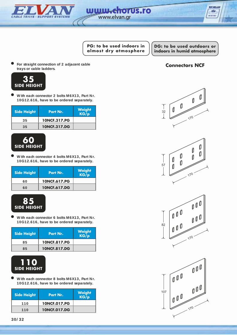
For straight connection of 2 adjacent cable trays or cable ladders.
• Connectors NCF
Side Height Part Nr. Weight KG/p
35 10NCF.317.PG
35 10NCF.317.DG
PG: to be used indoors in almost dry atmosphere
DG: to be used outdoors or indoors in humid atmosphere
35SIDE HEIGHT
With each connector 2 bolts M6X13, Part Nr. 10G12.616, have to be ordered separately.
•
Side Height Part Nr. Weight KG/p
60 10NCF.617.PG
60 10NCF.617.DG
60SIDE HEIGHT
With each connector 4 bolts M6X13, Part Nr. 10G12.616, have to be ordered separately.
•
Side Height Part Nr. Weight KG/p
85 10NCF.817.PG
85 10NCF.817.DG
85SIDE HEIGHT
With each connector 6 bolts M6X13, Part Nr. 10G12.616, have to be ordered separately.
•
Side Height Part Nr. Weight KG/p
110 10NCF.017.PG
110 10NCF.017.DG
110SIDE HEIGHT
With each connector 8 bolts M6X13, Part Nr. 10G12.616, have to be ordered separately.
•
www.chorus.ro
30/33
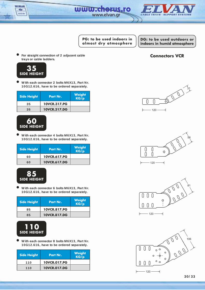
For straight connection of 2 adjacent cable trays or cable ladders.
• Connectors VCR
Side Height Part Nr. Weight KG/p
35 10VCR.317.PG
35 10VCR.317.DG
PG: to be used indoors in almost dry atmosphere
DG: to be used outdoors or indoors in humid atmosphere
35SIDE HEIGHT
With each connector 2 bolts M6X13, Part Nr. 10G12.616, have to be ordered separately.
•
Side Height Part Nr. Weight KG/p
60 10VCR.617.PG
60 10VCR.617.DG
60SIDE HEIGHT
With each connector 4 bolts M6X13, Part Nr. 10G12.616, have to be ordered separately.
•
Side Height Part Nr. Weight KG/p
85 10VCR.817.PG
85 10VCR.817.DG
85SIDE HEIGHT
With each connector 6 bolts M6X13, Part Nr. 10G12.616, have to be ordered separately.
•
Side Height Part Nr. Weight KG/p
110 10VCR.017.PG
110 10VCR.017.DG
110SIDE HEIGHT
With each connector 8 bolts M6X13, Part Nr. 10G12.616, have to be ordered separately.
•
www.chorus.ro
30/34
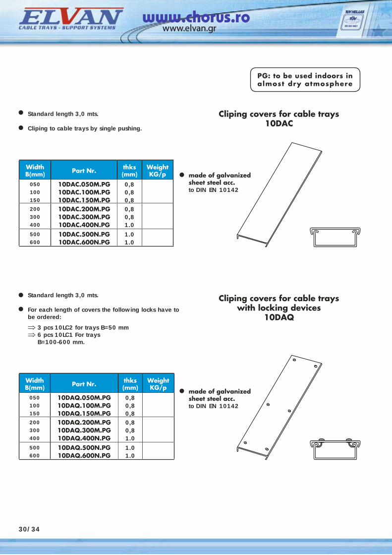
Standard length 3,0 mts.
Cliping to cable trays by single pushing.
PG: to be used indoors in almost dry atmosphere
WidthΒ(mm) Part Nr. thks
(mm)Weight KG/p
050100150
10DAC.050M.PG10DAC.100M.PG10DAC.150M.PG
0,80,80,8
200300400
10DAC.200M.PG10DAC.300M.PG10DAC.400N.PG
0,80,81.0
500600
10DAC.500N.PG 10DAC.600N.PG
1.01.0
•
Cliping covers for cable trays10DAC
••
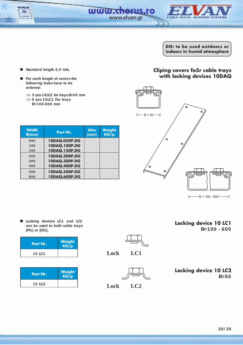
Standard length 3,0 mts.
For each length of covers the following locks have to be ordered:
⇒ 3 pcs 10LC2 for trays B=50 mm⇒ 6 pcs 10LC1 For trays B=100-600 mm.
•
WidthΒ(mm) Part Nr. thks
(mm)Weight KG/p
050100150
10DAQ.050M.PG10DAQ.100M.PG10DAQ.150M.PG
0,80,80,8
200300400
10DAQ.200M.PG10DAQ.300M.PG10DAQ.400N.PG
0,80,81.0
500600
10DAQ.500N.PG 10DAQ.600N.PG
1.01.0
•
Cliping covers for cable trayswith locking devices
10DAQ•
made of galvanized sheet steel acc.to DIN EN 10142
made of galvanized sheet steel acc.to DIN EN 10142
www.chorus.ro
30/35
DG: to be used outdoors or indoors in humid atmosphere
WidthΒ(mm) Part Nr. thks
(mm)Weight KG/p
050100150
10DAQ.050P.DG10DAQ.100P.DG10DAQ.150P.DG
200300400
10DAQ.200P.DG10DAQ.300P.DG10DAQ.400P.DG
500600
10DAQ.500P.DG 10DAQ.600P.DG
Standard length 3,0 mts.
For each length of covers the following locks have to be ordered:
⇒ 3 pcs 10LC2 for trays B=50 mm⇒ 6 pcs 10LC1 For trays B=100-600 mm
• Cliping covers fo5r cable trayswith locking devices 10DAQ•
Locking devices LC1 and LC2 can be used to both cable trays (PG) or (DG).
•
Part Nr. Weight KG/p
10 LC1
Locking device 10 LC1B=100 - 600
Part Nr. Weight KG/p
10 LC2
Locking device 10 LC2B=50
Lock LC1
Lock LC2
www.chorus.ro
30/36
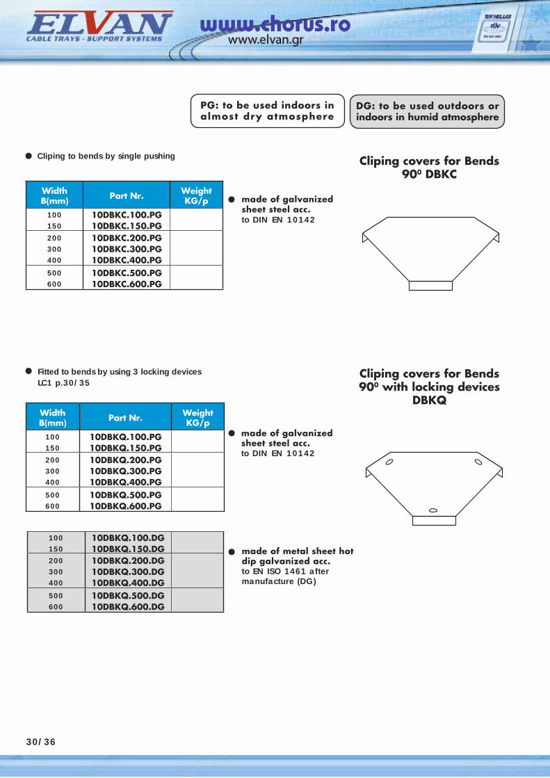
WidthΒ(mm) Part Nr. Weight
KG/p100150
10DBKC.100.PG10DBKC.150.PG
200300400
10DBKC.200.PG10DBKC.300.PG10DBKC.400.PG
500600
10DBKC.500.PG10DBKC.600.PG
100150
10DBKQ.100.DG10DBKQ.150.DG
200300400
10DBKQ.200.DG10DBKQ.300.DG10DBKQ.400.DG
500600
10DBKQ.500.DG10DBKQ.600.DG
PG: to be used indoors in almost dry atmosphere
DG: to be used outdoors or indoors in humid atmosphere
Cliping to bends by single pushing
• made of galvanized sheet steel acc.to DIN EN 10142
•
Fitted to bends by using 3 locking devices LC1 p.30/35
• made of galvanized sheet steel acc.to DIN EN 10142
•
• made of metal sheet hot dip galvanized acc.to EN ISO 1461 after manufacture (DG)
Cliping covers for Bends 900 DBKC
WidthΒ(mm) Part Nr. Weight
KG/p100150
10DBKQ.100.PG10DBKQ.150.PG
200300400
10DBKQ.200.PG10DBKQ.300.PG10DBKQ.400.PG
500600
10DBKQ.500.PG10DBKQ.600.PG
Cliping covers for Bends 900 with locking devices
DBKQ
www.chorus.ro

30/37
WidthΒ(mm) Part Nr. Weight
KG/p100150
10DBLC.100.PG10DBLC.150.PG
200300400
10DBLC.200.PG10DBLC.300.PG10DBLC.400.PG
500600
10DBLC.500.PG10DBLC.600.PG
100150
10DBLQ.100.DG10DBLQ.150.DG
200300400
10DBLQ.200.DG10DBLQ.300.DG10DBLQ.400.DG
500600
10DBLQ.500.DG10DBLQ.600.DG
PG: to be used indoors in almost dry atmosphere
DG: to be used outdoors or indoors in humid atmosphere
Cliping to bends by single pushing
• made of galvanized sheet steel acc.to DIN EN 10142
•
Fitted to bends by using 3 locking devices LC1 p.30/35
• made of galvanized sheet steel acc.to DIN EN 10142
•
• made of metal sheet hot dip galvanized acc.to EN ISO 1461 after manufacture (DG)
Cliping covers for Bends 450 DBLC
WidthΒ(mm) Part Nr. Weight
KG/p100150
10DBLQ.100.PG10DBLQ.150.PG
200300400
10DBLQ.200.PG10DBLQ.300.PG10DBLQ.400.PG
500600
10DBLQ.500.PG10DBLQ.600.PG
Cliping covers for Bends 450 with locking devices
DBLQ
www.chorus.ro
30/38
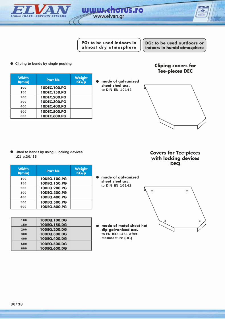
WidthΒ(mm) Part Nr. Weight
KG/p100150
10DEC.100.PG10DEC.150.PG
200300400
10DEC.200.PG10DEC.300.PG10DEC.400.PG
500600
10DEC.500.PG10DEC.600.PG
100150
10DEQ.100.DG10DEQ.150.DG
200300400
10DEQ.200.DG10DEQ.300.DG10DEQ.400.DG
500600
10DEQ.500.DG10DEQ.600.DG
PG: to be used indoors in almost dry atmosphere
DG: to be used outdoors or indoors in humid atmosphere
Cliping to bends by single pushing
• made of galvanized sheet steel acc.to DIN EN 10142
•
Fitted to bends by using 3 locking devices LC1 p.30/35
• made of galvanized sheet steel acc.to DIN EN 10142
•
• made of metal sheet hot dip galvanized acc.to EN ISO 1461 after manufacture (DG)
Cliping covers for Tee-pieces DEC
WidthΒ(mm) Part Nr. Weight
KG/p100150
10DEQ.100.PG10DEQ.150.PG
200300400
10DEQ.200.PG10DEQ.300.PG10DEQ.400.PG
500600
10DEQ.500.PG10DEQ.600.PG
Covers for Tee-pieces with locking devices
DEQ
www.chorus.ro
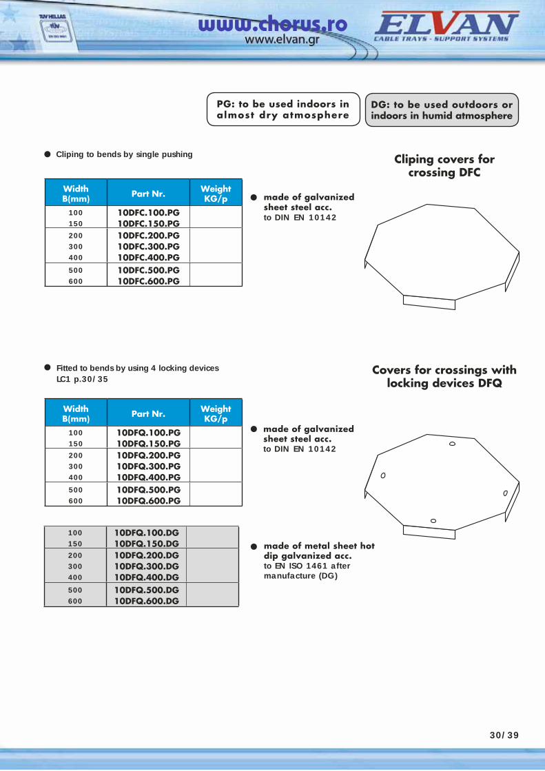
WidthΒ(mm) Part Nr. Weight
KG/p100150
10DFC.100.PG10DFC.150.PG
200300400
10DFC.200.PG10DFC.300.PG10DFC.400.PG
500600
10DFC.500.PG10DFC.600.PG
100150
10DFQ.100.DG10DFQ.150.DG
200300400
10DFQ.200.DG10DFQ.300.DG10DFQ.400.DG
500600
10DFQ.500.DG10DFQ.600.DG
PG: to be used indoors in almost dry atmosphere
DG: to be used outdoors or indoors in humid atmosphere
Cliping to bends by single pushing
• made of galvanized sheet steel acc.to DIN EN 10142
•
Fitted to bends by using 4 locking devices LC1 p.30/35
• made of galvanized sheet steel acc.to DIN EN 10142
•
•
Cliping covers for crossing DFC
WidthΒ(mm) Part Nr. Weight
KG/p100150
10DFQ.100.PG10DFQ.150.PG
200300400
10DFQ.200.PG10DFQ.300.PG10DFQ.400.PG
500600
10DFQ.500.PG10DFQ.600.PG
Covers for crossings withlocking devices DFQ
30/39
made of metal sheet hot dip galvanized acc.to EN ISO 1461 after manufacture (DG)
www.chorus.ro
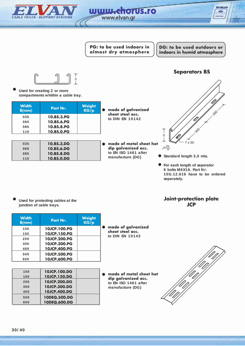
30/40
WidthΒ(mm) Part Nr. Weight
KG/p
035060085110
10.BS.3.PG10.BS.6.PG10.BS.8.PG10.BS.0.PG
100150
10JCP.100.DG10JCP.150.DG
200300400
10JCP.200.DG10JCP.300.DG10JCP.400.DG
500600
10DEQ.500.DG10DEQ.600.DG
PG: to be used indoors in almost dry atmosphere
DG: to be used outdoors or indoors in humid atmosphere
• made of galvanized sheet steel acc.to DIN EN 10142
• made of galvanized sheet steel acc.to DIN EN 10142
• made of metal sheet hot dip galvanized acc.to EN ISO 1461 after manufacture (DG)
Separators BS
WidthΒ(mm) Part Nr. Weight
KG/p100150
10JCP.100.PG10JCP.150.PG
200300400
10JCP.200.PG10JCP.300.PG10JCP.400.PG
500600
10JCP.500.PG10JCP.600.PG
Joint-protection plateJCP
035060085110
10.BS.3.DG10.BS.6.DG10.BS.8.DG10.BS.0.DG
• made of metal sheet hot dip galvanized acc.to EN ISO 1461 after manufacture (DG) Standard length 3,0 mts.
For each length of seperator 6 bolts M6X16. Part Nr. 10G.12.616 have to be ordered separately.
••
• Used for creating 2 or more compartments whithin a cable tray.
• Used for protecting cables at the junction of cable trays.
www.chorus.ro
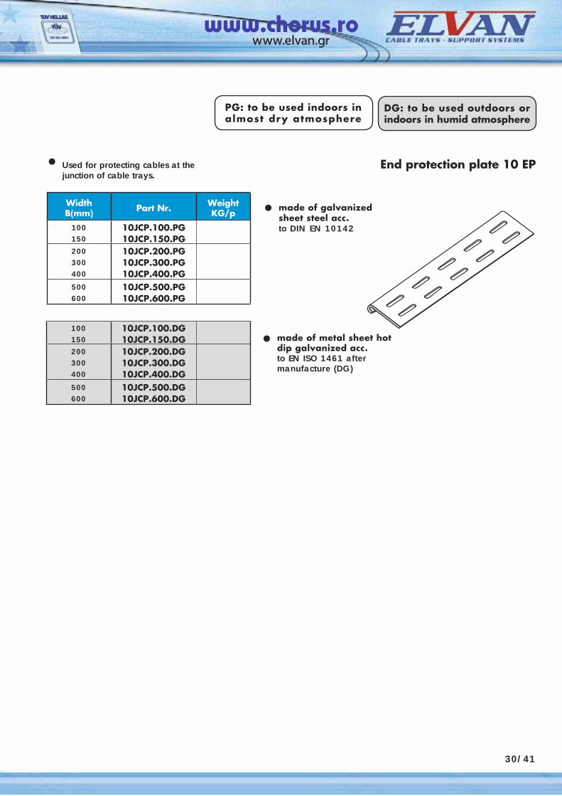
30/41
WidthΒ(mm) Part Nr. Weight
KG/p100150
10JCP.100.PG10JCP.150.PG
200300400
10JCP.200.PG10JCP.300.PG10JCP.400.PG
500600
10JCP.500.PG10JCP.600.PG
100150
10JCP.100.DG10JCP.150.DG
200300400
10JCP.200.DG10JCP.300.DG10JCP.400.DG
500600
10JCP.500.DG10JCP.600.DG
PG: to be used indoors in almost dry atmosphere
DG: to be used outdoors or indoors in humid atmosphere
• made of galvanized sheet steel acc.to DIN EN 10142
•
End protection plate 10 EP
made of metal sheet hot dip galvanized acc.to EN ISO 1461 after manufacture (DG)
• Used for protecting cables at the junction of cable trays.
www.chorus.ro
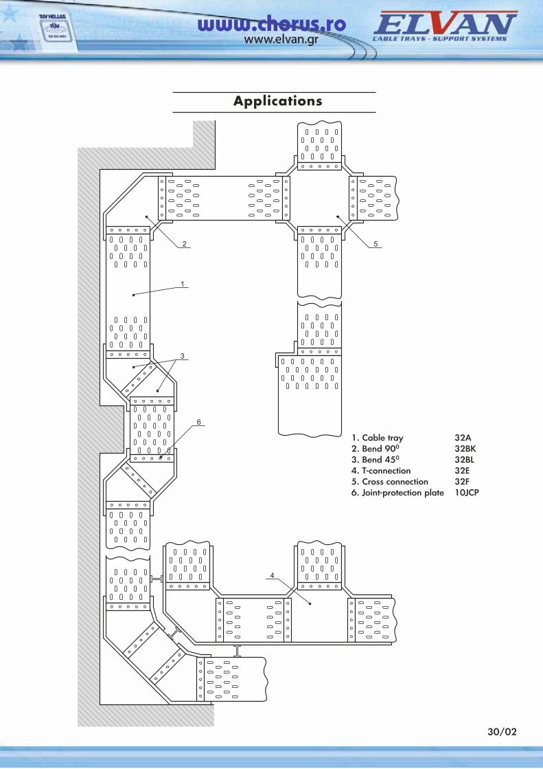
30/22
Applications
30/02
1. Cable tray 32A2. Bend 900 32BK3. Bend 450 32BL4. T-connection 32E5. Cross connection 32F6. Joint-protection plate 10JCP
www.chorus.ro
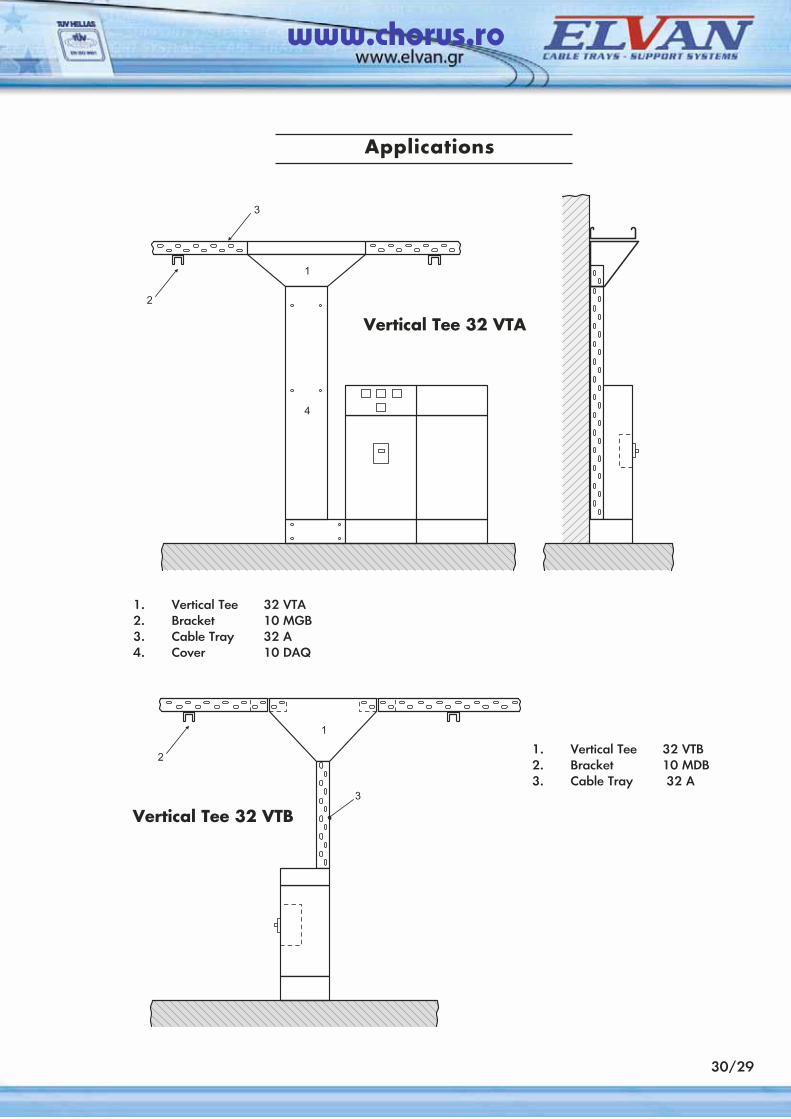
30/29
1. Vertical Tee 32 VTA2. Bracket 10 MGB3. Cable Tray 32 A4. Cover 10 DAQ
1. Vertical Tee 32 VTB2. Bracket 10 MDB3. Cable Tray 32 Α
Applications
Vertical Tee 32 VTB
Vertical Tee 32 VTA
www.chorus.ro
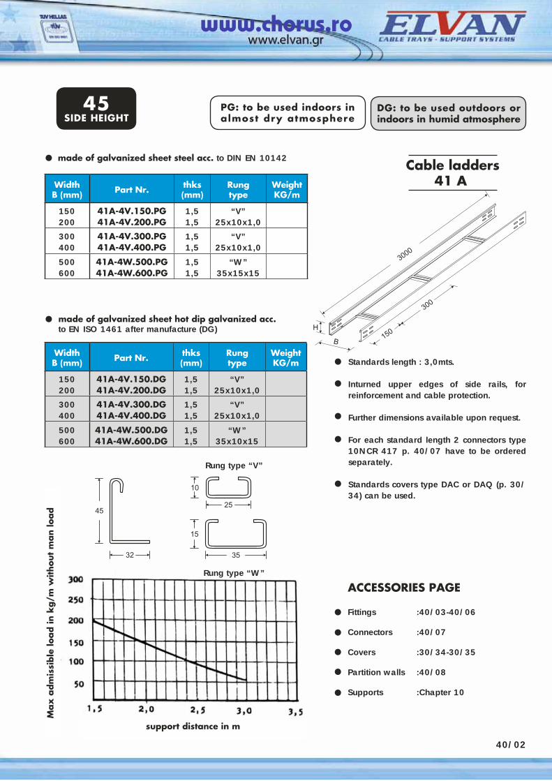
DG: to be used outdoors or indoors in humid atmosphere
30/22
PG: to be used indoors in almost dry atmosphere
Applications see below•
Standards length : 3,0mts.
Inturned upper edges of side rails, for reinforcement and cable protection.
Further dimensions available upon request.
For each standard length 2 connectors type 10NCR 417 p. 40/07 have to be ordered separately.
Standards covers type DAC or DAQ (p. 30/34) can be used.
Cable ladders41 AWidth
Β (mm) Part Nr. thks(mm)
Rungtype
WeightKG/m
150200
41A-4V.150.PG41A-4V.200.PG
1,51,5
“V”25x10x1,0
300400
41A-4V.300.PG41A-4V.400.PG
1,51,5
“V”25x10x1,0
500600
41A-4W.500.PG41A-4W.600.PG
1,51,5
“W”35x15x15
made of galvanized sheet hot dip galvanized acc. to EN ISO 1461 after manufacture (DG)
•
••
••
•
ACCESSORIES PAGE Fittings :40/03-40/06
Connectors :40/07
Covers :30/34-30/35
Partition walls :40/08
Supports :Chapter 10
•••••
made of galvanized sheet steel acc. to DIN EN 10142•
PG: to be used indoors in almost dry atmosphere
DG: to be used outdoors or indoors in humid atmosphere
45SIDE HEIGHT
WidthΒ (mm) Part Nr. thks
(mm)Rungtype
WeightKG/m
150200
41A-4V.150.DG41A-4V.200.DG
1,51,5
“V”25x10x1,0
300400
41A-4V.300.DG41A-4V.400.DG
1,51,5
“V”25x10x1,0
500600
41A-4W.500.DG41A-4W.600.DG
1,51,5
“W”35x10x15
Rung type “W”
Rung type “V”
support distance in m
Max
adm
issi
ble
load in
kg/m
without
man lo
ad
40/02
www.chorus.ro
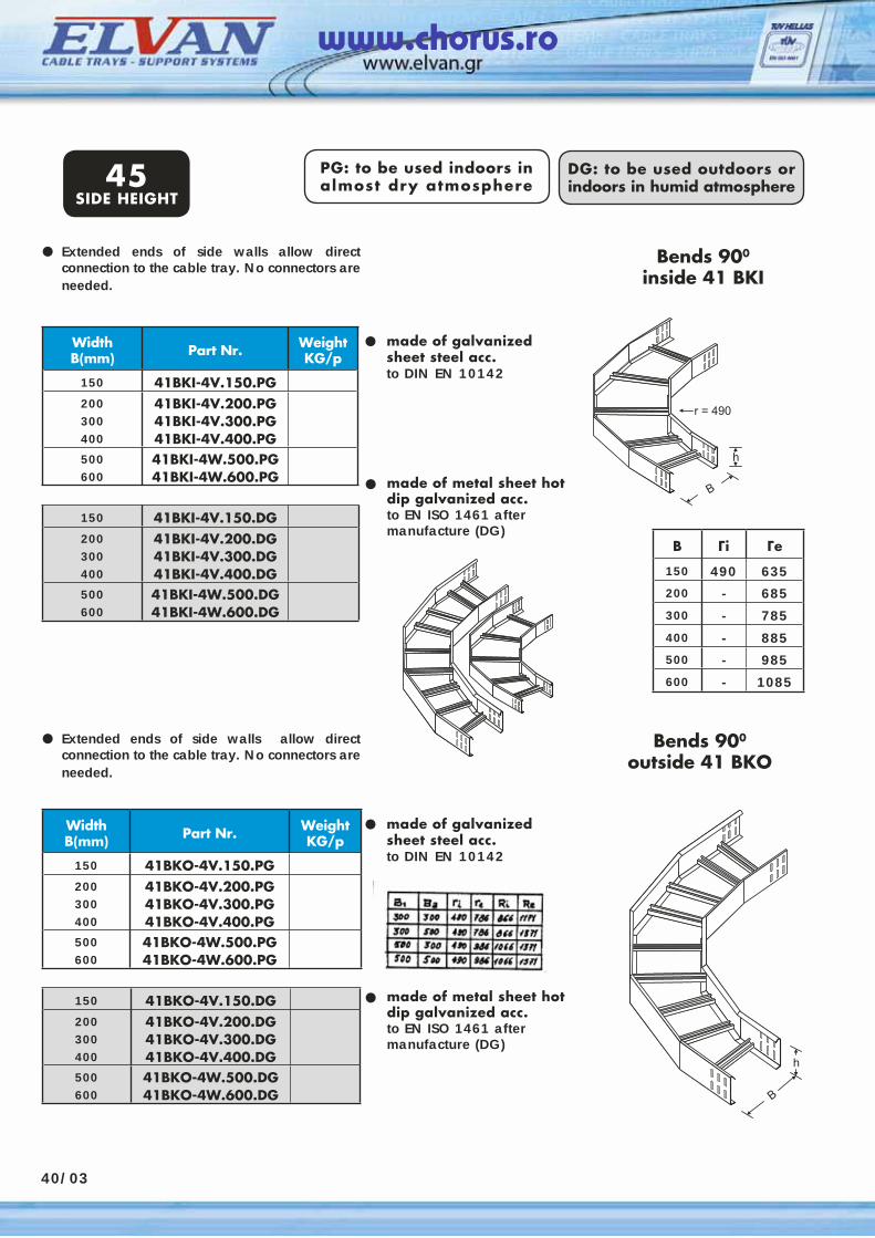
40/03
WidthΒ(mm) Part Nr. Weight
KG/p
150 41BKI-4V.150.PG200300400
41BKI-4V.200.PG41BKI-4V.300.PG41BKI-4V.400.PG
500600
41BKI-4W.500.PG41BKI-4W.600.PG
PG: to be used indoors in almost dry atmosphere
DG: to be used outdoors or indoors in humid atmosphere
Extended ends of side walls allow direct connection to the cable tray. No connectors are needed.
• made of galvanized sheet steel acc.to DIN EN 10142
•
•
Bends 900
inside 41 BKI
Bends 900
outside 41 BKO
made of metal sheet hot dip galvanized acc.to EN ISO 1461 after manufacture (DG)
150 41BKI-4V.150.DG200300400
41BKI-4V.200.DG41BKI-4V.300.DG41BKI-4V.400.DG
500600
41BKI-4W.500.DG41BKI-4W.600.DG
WidthΒ(mm) Part Nr. Weight
KG/p
150 41BKΟ-4V.150.PG200300400
41BKΟ-4V.200.PG41BKΟ-4V.300.PG41BKΟ-4V.400.PG
500600
41BKΟ-4W.500.PG41BKΟ-4W.600.PG
Extended ends of side walls allow direct connection to the cable tray. No connectors are needed.
• made of galvanized sheet steel acc.to DIN EN 10142
•
• made of metal sheet hot dip galvanized acc.to EN ISO 1461 after manufacture (DG)
150 41BKΟ-4V.150.DG200300400
41BKΟ-4V.200.DG41BKΟ-4V.300.DG41BKΟ-4V.400.DG
500600
41BKΟ-4W.500.DG41BKΟ-4W.600.DG
45SIDE HEIGHT
B Γi Γe
150 490 635200 - 685300 - 785
400 - 885500 - 985600 - 1085
www.chorus.ro
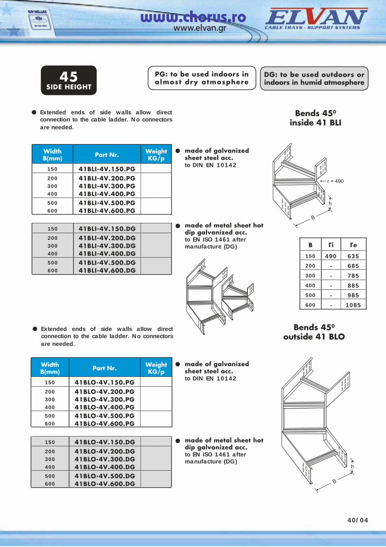
40/04
WidthΒ(mm) Part Nr. Weight
KG/p
150 41BLI-4V.150.PG200300400
41BLI-4V.200.PG41BLI-4V.300.PG41BLI-4V.400.PG
500600
41BLI-4V.500.PG41BLI-4V.600.PG
PG: to be used indoors in almost dry atmosphere
DG: to be used outdoors or indoors in humid atmosphere
•
•
Bends 450
inside 41 BLI
150 41BLI-4V.150.DG200300400
41BLI-4V.200.DG41BLI-4V.300.DG41BLI-4V.400.DG
500600
41BLI-4V.500.DG41BLI-4V.600.DG
WidthΒ(mm) Part Nr. Weight
KG/p
150 41BLΟ-4V.150.PG200300400
41BLΟ-4V.200.PG41BLΟ-4V.300.PG41BLΟ-4V.400.PG
500600
41BLΟ-4V.500.PG41BLΟ-4V.600.PG
•
• made of metal sheet hot dip galvanized acc.to EN ISO 1461 after manufacture (DG)
150 41BLΟ-4V.150.DG200300400
41BLΟ-4V.200.DG41BLΟ-4V.300.DG41BLΟ-4V.400.DG
500600
41BLΟ-4V.500.DG41BLΟ-4V.600.DG
made of galvanized sheet steel acc.to DIN EN 10142
Bends 450
outside 41 BLO
made of metal sheet hot dip galvanized acc.to EN ISO 1461 after manufacture (DG)
made of galvanized sheet steel acc.to DIN EN 10142
45SIDE HEIGHT
Extended ends of side walls allow direct connection to the cable ladder. No connectors are needed.
•
• Extended ends of side walls allow direct connection to the cable ladder. No connectors are needed.
B Γi Γe
150 490 635200 - 685300 - 785
400 - 885500 - 985600 - 1085
www.chorus.ro
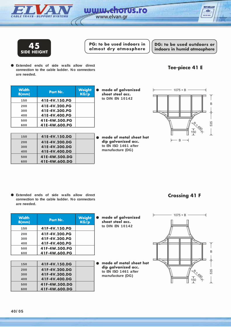
40/05
PG: to be used indoors in almost dry atmosphere
DG: to be used outdoors or indoors in humid atmosphere
Extended ends of side walls allow direct connection to the cable ladder. No connectors are needed.
•
•
•
Tee-piece 41 E
150 41E-4V.150.DG200300400
41E-4V.200.DG41E-4V.300.DG41E-4V.400.DG
500600
41E-4W.500.DG41E-4W.600.DG
WidthΒ(mm) Part Nr. Weight
KG/p
150 41F-4V.150.PG200300400
41F-4V.200.PG41F-4V.300.PG41F-4V.400.PG
500600
41F-4W.500.PG41F-4W.600.PG
•
•
• made of metal sheet hot dip galvanized acc.to EN ISO 1461 after manufacture (DG)
150 41F-4V.150.DG200300400
41F-4V.200.DG41F-4V.300.DG41F-4V.400.DG
500600
41F-4W.500.DG41F-4W.600.DG
made of galvanized sheet steel acc.to DIN EN 10142
Crossing 41 F
made of metal sheet hot dip galvanized acc.to EN ISO 1461 after manufacture (DG)
Extended ends of side walls allow direct connection to the cable ladder. No connectors are needed.
made of galvanized sheet steel acc.to DIN EN 10142
45SIDE HEIGHT
WidthΒ(mm) Part Nr. Weight
KG/p
150 41Ε-4V.150.PG200300400
41Ε-4V.200.PG41Ε-4V.300.PG41Ε-4V.400.PG
500600
41Ε-4W.500.PG41Ε-4W.600.PG
www.chorus.ro
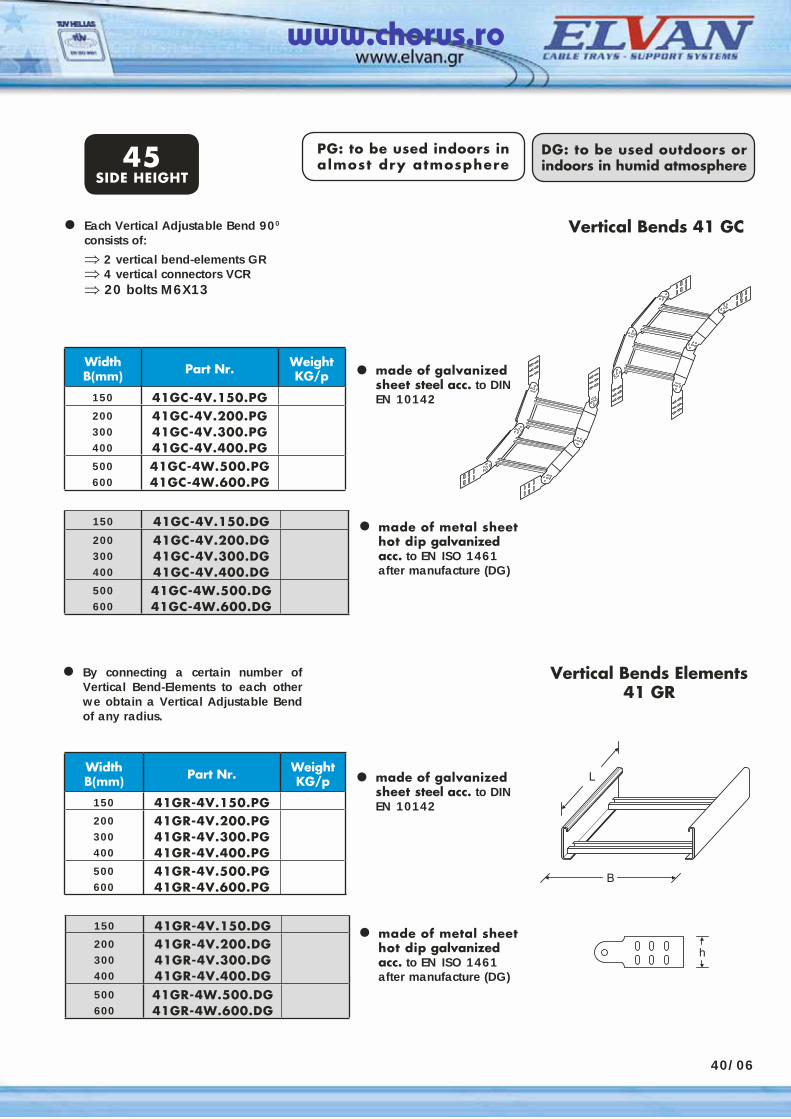
40/06
150 41GC-4V.150.DG200300400
41GC-4V.200.DG41GC-4V.300.DG41GC-4V.400.DG
500600
41GC-4W.500.DG41GC-4W.600.DG
WidthΒ(mm) Part Nr. Weight
KG/p
150 41GC-4V.150.PG200300400
41GC-4V.200.PG41GC-4V.300.PG41GC-4V.400.PG
500600
41GC-4W.500.PG41GC-4W.600.PG
150 41GR-4V.150.DG200300400
41GR-4V.200.DG41GR-4V.300.DG41GR-4V.400.DG
500600
41GR-4W.500.DG41GR-4W.600.DG
WidthΒ(mm) Part Nr. Weight
KG/p
150 41GR-4V.150.PG200300400
41GR-4V.200.PG41GR-4V.300.PG41GR-4V.400.PG
500600
41GR-4V.500.PG41GR-4V.600.PG
PG: to be used indoors in almost dry atmosphere
DG: to be used outdoors or indoors in humid atmosphere
Vertical Bends Elements41 GR
Each Vertical Adjustable Bend 900 consists of:⇒ 2 vertical bend-elements GR⇒ 4 vertical connectors VCR⇒ 20 bolts M6X13
•
•
•
Vertical Bends 41 GC
• made of galvanized sheet steel acc. to DINEN 10142
made of metal sheet hot dip galvanized acc. to EN ISO 1461 after manufacture (DG)
By connecting a certain number of Vertical Bend-Elements to each other we obtain a Vertical Adjustable Bend of any radius.
•
45SIDE HEIGHT
• made of metal sheet hot dip galvanized acc. to EN ISO 1461 after manufacture (DG)
made of galvanized sheet steel acc. to DINEN 10142
www.chorus.ro
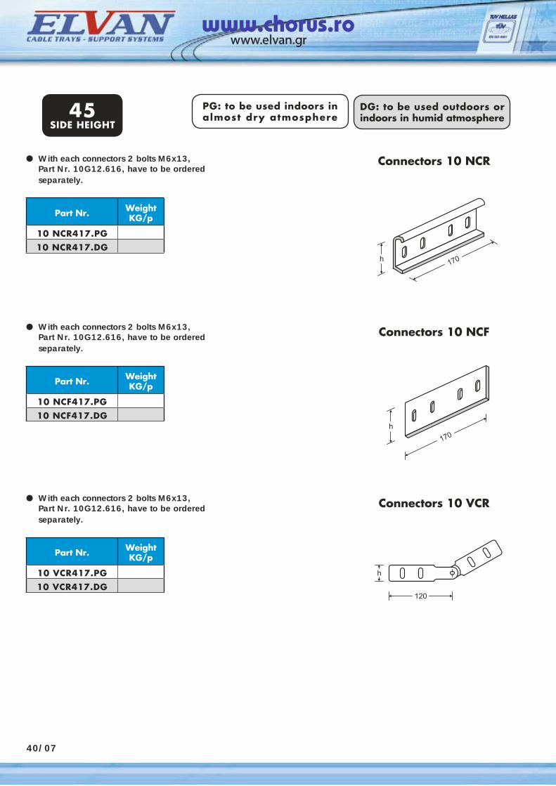
40/07
PG: to be used indoors in almost dry atmosphere
DG: to be used outdoors or indoors in humid atmosphere
With each connectors 2 bolts M6x13, Part Nr. 10G12.616, have to be ordered separately.
•
45SIDE HEIGHT
Part Nr. Weight KG/p
10 NCR417.PG10 NCR417.DG
With each connectors 2 bolts M6x13, Part Nr. 10G12.616, have to be ordered separately.
•
Part Nr. Weight KG/p
10 NCF417.PG10 NCF417.DG
With each connectors 2 bolts M6x13, Part Nr. 10G12.616, have to be ordered separately.
•
Part Nr. Weight KG/p
10 VCR417.PG10 VCR417.DG
Connectors 10 NCR
Connectors 10 NCF
Connectors 10 VCR
www.chorus.ro
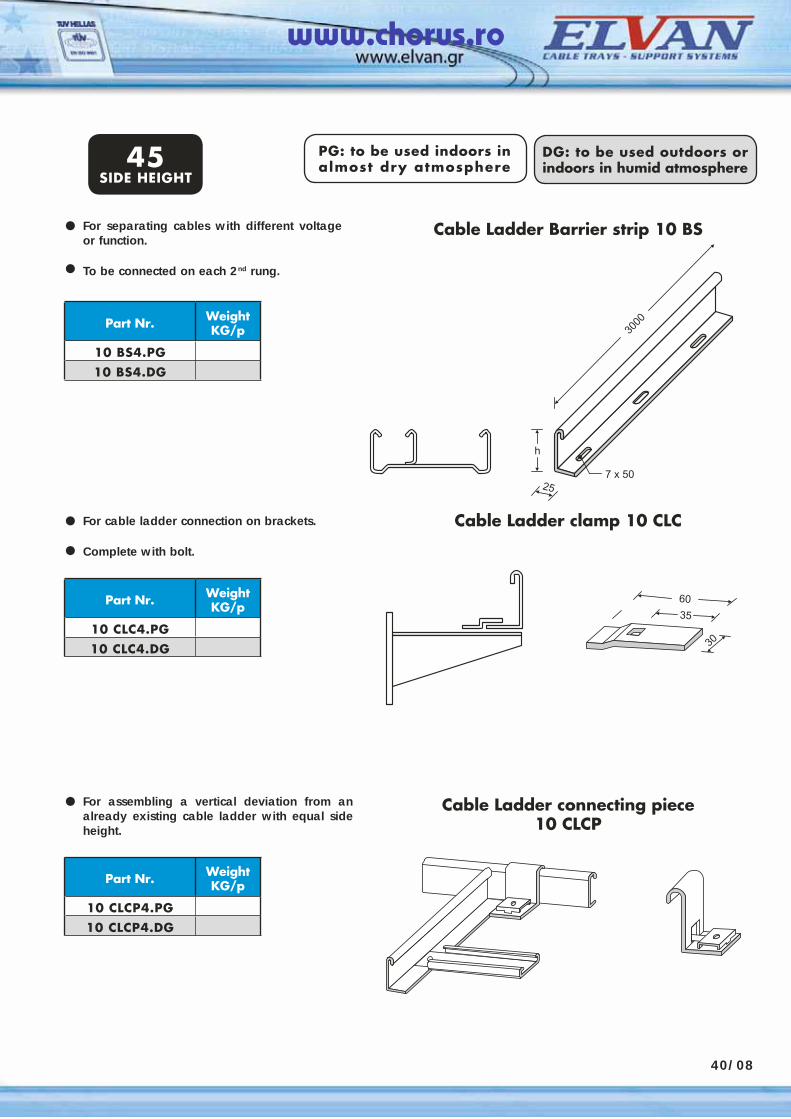
PG: to be used indoors in almost dry atmosphere
DG: to be used outdoors or indoors in humid atmosphere
For separating cables with different voltage or function.
To be connected on each 2nd rung.
•
45SIDE HEIGHT
Part Nr. Weight KG/p
10 BS4.PG10 BS4.DG
Cable Ladder Barrier strip 10 BS
40/08
•
For cable ladder connection on brackets.
Complete with bolt.
•
Part Nr. Weight KG/p
10 CLC4.PG10 CLC4.DG
Cable Ladder clamp 10 CLC
•
For assembling a vertical deviation from an already existing cable ladder with equal side height.
•
Part Nr. Weight KG/p
10 CLCP4.PG10 CLCP4.DG
Cable Ladder connecting piece 10 CLCP
www.chorus.ro
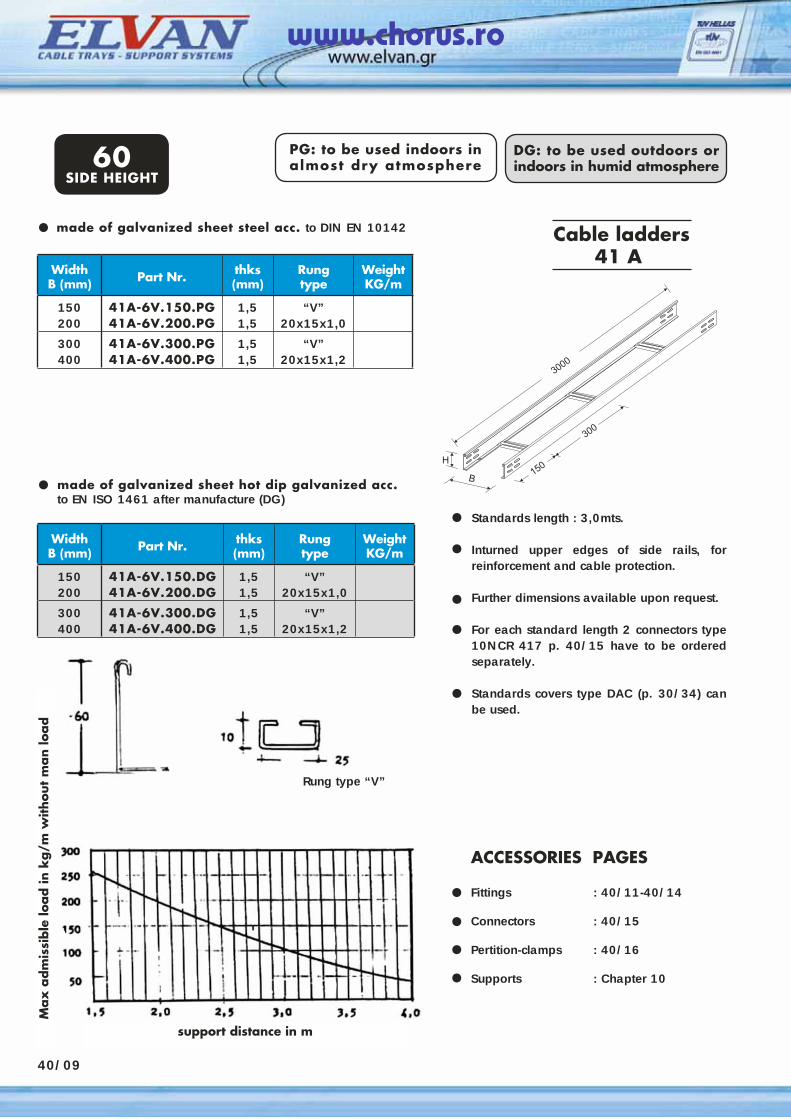
Standards length : 3,0mts.
Inturned upper edges of side rails, for reinforcement and cable protection.
Further dimensions available upon request.
For each standard length 2 connectors type 10NCR 417 p. 40/15 have to be ordered separately.
Standards covers type DAC (p. 30/34) can be used.
Cable ladders41 A
WidthΒ (mm) Part Nr. thks
(mm)Rungtype
WeightKG/m
150200
41A-6V.150.PG41A-6V.200.PG
1,51,5
“V”20x15x1,0
300400
41A-6V.300.PG41A-6V.400.PG
1,51,5
“V”20x15x1,2
made of galvanized sheet hot dip galvanized acc. to EN ISO 1461 after manufacture (DG)
•••
••
•
ACCESSORIES PAGES Fittings : 40/11-40/14
Connectors : 40/15
Pertition-clamps : 40/16 Supports : Chapter 10
••••
made of galvanized sheet steel acc. to DIN EN 10142•
PG: to be used indoors in almost dry atmosphere
DG: to be used outdoors or indoors in humid atmosphere60
SIDE HEIGHT
WidthΒ (mm) Part Nr. thks
(mm)Rungtype
WeightKG/m
150200
41A-6V.150.DG41A-6V.200.DG
1,51,5
“V”20x15x1,0
300400
41A-6V.300.DG41A-6V.400.DG
1,51,5
“V”20x15x1,2
Rung type “V”
support distance in m
Max
adm
issi
ble
load in
kg/m
without
man lo
ad
40/09
www.chorus.ro
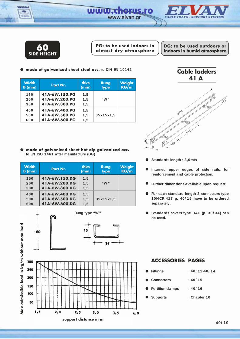
40/10
Standards length : 3,0mts.
Inturned upper edges of side rails, for reinforcement and cable protection.
Further dimensions available upon request.
For each standard length 2 connectors type 10NCR 417 p. 40/15 have to be ordered separately.
Standards covers type DAC (p. 30/34) can be used.
Cable ladders41 A
WidthΒ (mm) Part Nr. thks
(mm)Rungtype
WeightKG/m
150200300
41A-6W.150.PG41A-6W.200.PG41A-6W.300.PG
1,51,51,5
“W”
400500600
41A-6W.400.PG41A-6W.500.PG41A*6W.600.PG
1,51,51,5
35x15x1,5
made of galvanized sheet hot dip galvanized acc. to EN ISO 1461 after manufacture (DG)
•••
••
•
ACCESSORIES PAGES Fittings : 40/11-40/14
Connectors : 40/15
Pertition-clamps : 40/16 Supports : Chapter 10
••••
made of galvanized sheet steel acc. to DIN EN 10142•
PG: to be used indoors in almost dry atmosphere
DG: to be used outdoors or indoors in humid atmosphere60
SIDE HEIGHT
Rung type “W”
support distance in m
Max
adm
issi
ble
load in
kg/m
without
man lo
ad
WidthΒ (mm) Part Nr. thks
(mm)Rungtype
WeightKG/m
150200300
41A-6W.150.DG41A-6W.200.DG41A-6W.300.DG
1,51,51,5
“W”
400500600
41A-6W.400.DG41A-6W.500.DG41A*6W.600.DG
1,51,51,5
35x15x1,5
www.chorus.ro
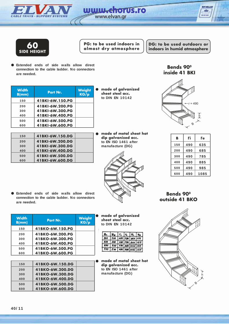
40/11
WidthΒ(mm) Part Nr. Weight
KG/p
150 41BKI-6W.150.PG200300400
41BKI-6W.200.PG41BKI-6W.300.PG41BKI-6W.400.PG
500600
41BKI-6W.500.PG41BKI-6W.600.PG
PG: to be used indoors in almost dry atmosphere
DG: to be used outdoors or indoors in humid atmosphere
Extended ends of side walls allow direct connection to the cable ladder. No connectors are needed.
•
•
•
Bends 900
inside 41 BKI
150 41BKI-6W.150.DG200300400
41BKI-6W.200.DG41BKI-6W.300.DG41BKI-6W.400.DG
500600
41BKI-6W.500.DG41BKI-6W.600.DG
WidthΒ(mm) Part Nr. Weight
KG/p
150 41BKΟ-6W.150.PG200300400
41BKΟ-6W.200.PG41BKΟ-6W.300.PG41BKΟ-6W.400.PG
500600
41BKΟ-6W.500.PG41BKΟ-6W.600.PG
•
•
• made of metal sheet hot dip galvanized acc.to EN ISO 1461 after manufacture (DG)
150 41BKΟ-6W.150.DG200300400
41BKΟ-6W.200.DG41BKΟ-6W.300.DG41BKΟ-6W.400.DG
500600
41BKΟ-6W.500.DG41BKΟ-6W.600.DG
made of galvanized sheet steel acc.to DIN EN 10142
Bends 900
outside 41 BKO
made of metal sheet hot dip galvanized acc.to EN ISO 1461 after manufacture (DG)
Extended ends of side walls allow direct connection to the cable ladder. No connectors are needed.
made of galvanized sheet steel acc.to DIN EN 10142
60SIDE HEIGHT
B Γi Γe
150 490 635200 490 685300 490 785
400 490 885500 490 985600 490 1085
www.chorus.ro
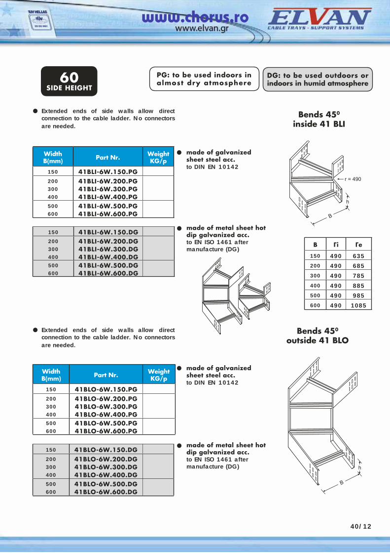
WidthΒ(mm) Part Nr. Weight
KG/p
150 41BLI-6W.150.PG200300400
41BLI-6W.200.PG41BLI-6W.300.PG41BLI-6W.400.PG
500600
41BLI-6W.500.PG41BLI-6W.600.PG
PG: to be used indoors in almost dry atmosphere
DG: to be used outdoors or indoors in humid atmosphere
Extended ends of side walls allow direct connection to the cable ladder. No connectors are needed.
•
•
•
Bends 450
inside 41 BLI
150 41BLI-6W.150.DG200300400
41BLI-6W.200.DG41BLI-6W.300.DG41BLI-6W.400.DG
500600
41BLI-6W.500.DG41BLI-6W.600.DG
WidthΒ(mm) Part Nr. Weight
KG/p
150 41BLΟ-6W.150.PG200300400
41BLΟ-6W.200.PG41BLΟ-6W.300.PG41BLΟ-6W.400.PG
500600
41BLΟ-6W.500.PG41BLΟ-6W.600.PG
•
•
• made of metal sheet hot dip galvanized acc.to EN ISO 1461 after manufacture (DG)
150 41BLΟ-6W.150.DG200300400
41BLΟ-6W.200.DG41BLΟ-6W.300.DG41BLΟ-6W.400.DG
500600
41BLΟ-6W.500.DG41BLΟ-6W.600.DG
made of galvanized sheet steel acc.to DIN EN 10142
Bends 450
outside 41 BLOExtended ends of side walls allow direct connection to the cable ladder. No connectors are needed.
made of galvanized sheet steel acc.to DIN EN 10142
60SIDE HEIGHT
made of metal sheet hot dip galvanized acc.to EN ISO 1461 after manufacture (DG)
40/12
B Γi Γe
150 490 635200 490 685300 490 785
400 490 885500 490 985600 490 1085
www.chorus.ro
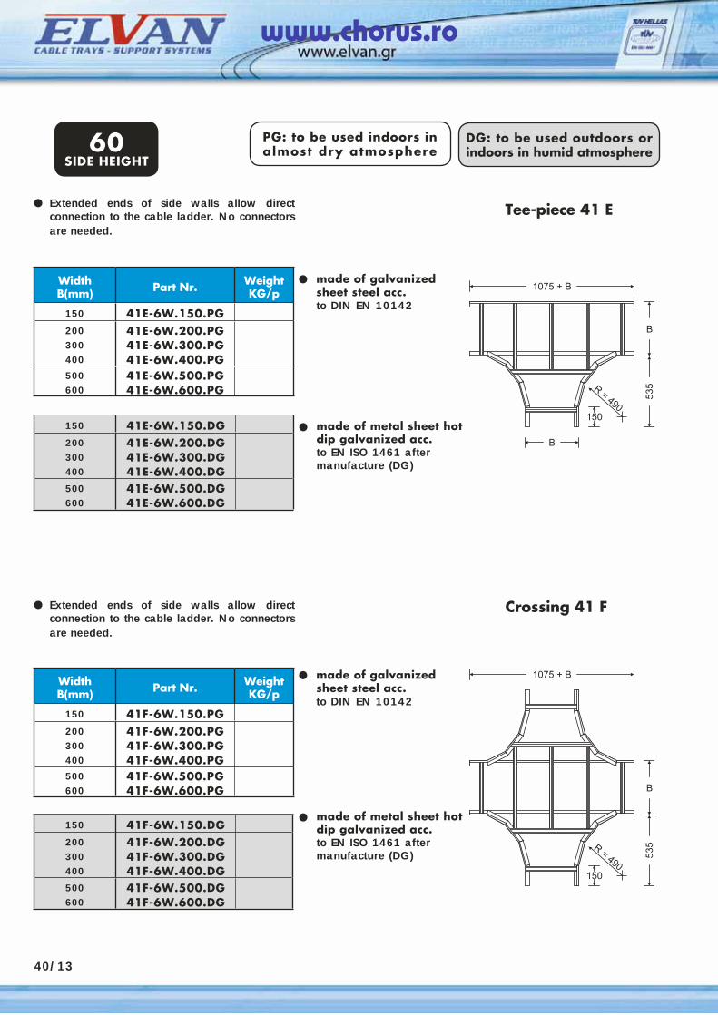
PG: to be used indoors in almost dry atmosphere
DG: to be used outdoors or indoors in humid atmosphere
Extended ends of side walls allow direct connection to the cable ladder. No connectors are needed.
•
•
•
Tee-piece 41 E
150 41E-6W.150.DG200300400
41E-6W.200.DG41E-6W.300.DG41E-6W.400.DG
500600
41E-6W.500.DG41E-6W.600.DG
WidthΒ(mm) Part Nr. Weight
KG/p
150 41F-6W.150.PG200300400
41F-6W.200.PG41F-6W.300.PG41F-6W.400.PG
500600
41F-6W.500.PG41F-6W.600.PG
•
•
• made of metal sheet hot dip galvanized acc.to EN ISO 1461 after manufacture (DG)
150 41F-6W.150.DG200300400
41F-6W.200.DG41F-6W.300.DG41F-6W.400.DG
500600
41F-6W.500.DG41F-6W.600.DG
made of galvanized sheet steel acc.to DIN EN 10142
Crossing 41 F
made of metal sheet hot dip galvanized acc.to EN ISO 1461 after manufacture (DG)
Extended ends of side walls allow direct connection to the cable ladder. No connectors are needed.
made of galvanized sheet steel acc.to DIN EN 10142
60SIDE HEIGHT
WidthΒ(mm) Part Nr. Weight
KG/p
150 41Ε-6W.150.PG200300400
41Ε-6W.200.PG41Ε-6W.300.PG41Ε-6W.400.PG
500600
41Ε-6W.500.PG41Ε-6W.600.PG
40/13
www.chorus.ro
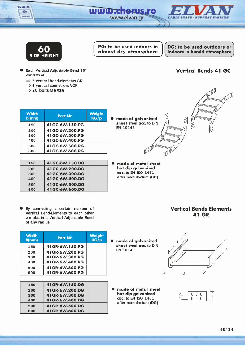
40/14
150 41GC-6W.150.DG200300400
41GC-6W.200.DG41GC-6W.300.DG41GC-6W.400.DG
500600
41GC-6W.500.DG41GC-6W.600.DG
WidthΒ(mm) Part Nr. Weight
KG/p
150 41GC-6W.150.PG200300400
41GC-6W.200.PG41GC-6W.300.PG41GC-6W.400.PG
500600
41GC-6W.500.PG41GC-6W.600.PG
150 41GR-6W.150.DG200300400
41GR-6W.200.DG41GR-6W.300.DG41GR-6W.400.DG
500600
41GR-6W.500.DG41GR-6W.600.DG
WidthΒ(mm) Part Nr. Weight
KG/p
150 41GR-6W.150.PG200300400
41GR-6W.200.PG41GR-6W.300.PG41GR-6W.400.PG
500600
41GR-6W.500.PG41GR-6W.600.PG
PG: to be used indoors in almost dry atmosphere
DG: to be used outdoors or indoors in humid atmosphere
Vertical Bends Elements41 GR
Each Vertical Adjustable Bend 900 consists of:⇒ 2 vertical bend-elements GR⇒ 4 vertical connectors VCF⇒ 20 bolts M6X16
•
•
•
Vertical Bends 41 GC
• made of galvanized sheet steel acc. to DINEN 10142
made of galvanized sheet steel acc. to DINEN 10142
made of metal sheet hot dip galvanized acc. to EN ISO 1461 after manufacture (DG)
By connecting a certain number of Vertical Bend-Elements to each other we obtain a Vertical Adjustable Bend of any radius.
•
60SIDE HEIGHT
• made of metal sheet hot dip galvanized acc. to EN ISO 1461 after manufacture (DG)
www.chorus.ro
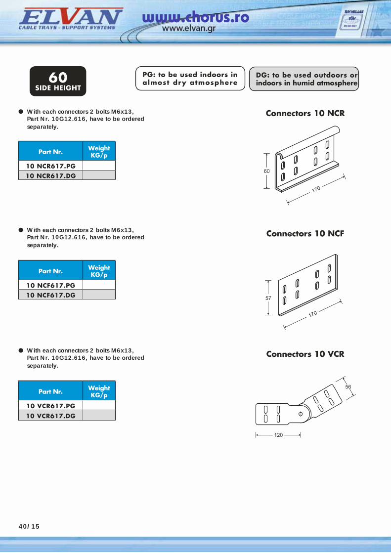
PG: to be used indoors in almost dry atmosphere
DG: to be used outdoors or indoors in humid atmosphere
With each connectors 2 bolts M6x13, Part Nr. 10G12.616, have to be ordered separately.
•
60SIDE HEIGHT
Part Nr. Weight KG/p
10 NCR617.PG10 NCR617.DG
With each connectors 2 bolts M6x13, Part Nr. 10G12.616, have to be ordered separately.
•
Part Nr. Weight KG/p
10 NCF617.PG10 NCF617.DG
With each connectors 2 bolts M6x13, Part Nr. 10G12.616, have to be ordered separately.
•
Part Nr. Weight KG/p
10 VCR617.PG
10 VCR617.DG
Connectors 10 NCR
Connectors 10 NCF
Connectors 10 VCR
40/15
www.chorus.ro
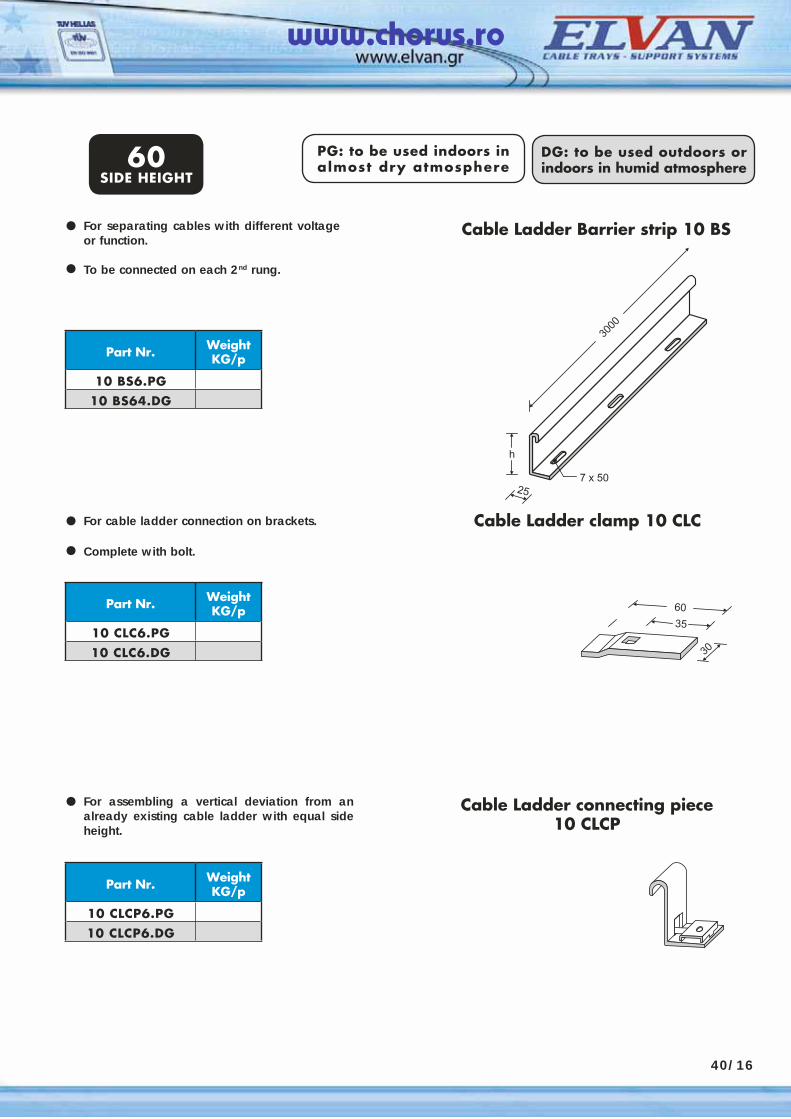
PG: to be used indoors in almost dry atmosphere
DG: to be used outdoors or indoors in humid atmosphere
For separating cables with different voltage or function.
To be connected on each 2nd rung.
•
60SIDE HEIGHT
Part Nr. Weight KG/p
10 BS6.PG10 BS64.DG
Cable Ladder Barrier strip 10 BS
•
For cable ladder connection on brackets.
Complete with bolt.
•
Part Nr. Weight KG/p
10 CLC6.PG10 CLC6.DG
Cable Ladder clamp 10 CLC
•
For assembling a vertical deviation from an already existing cable ladder with equal side height.
•
Part Nr. Weight KG/p
10 CLCP6.PG10 CLCP6.DG
Cable Ladder connecting piece 10 CLCP
40/16
www.chorus.ro
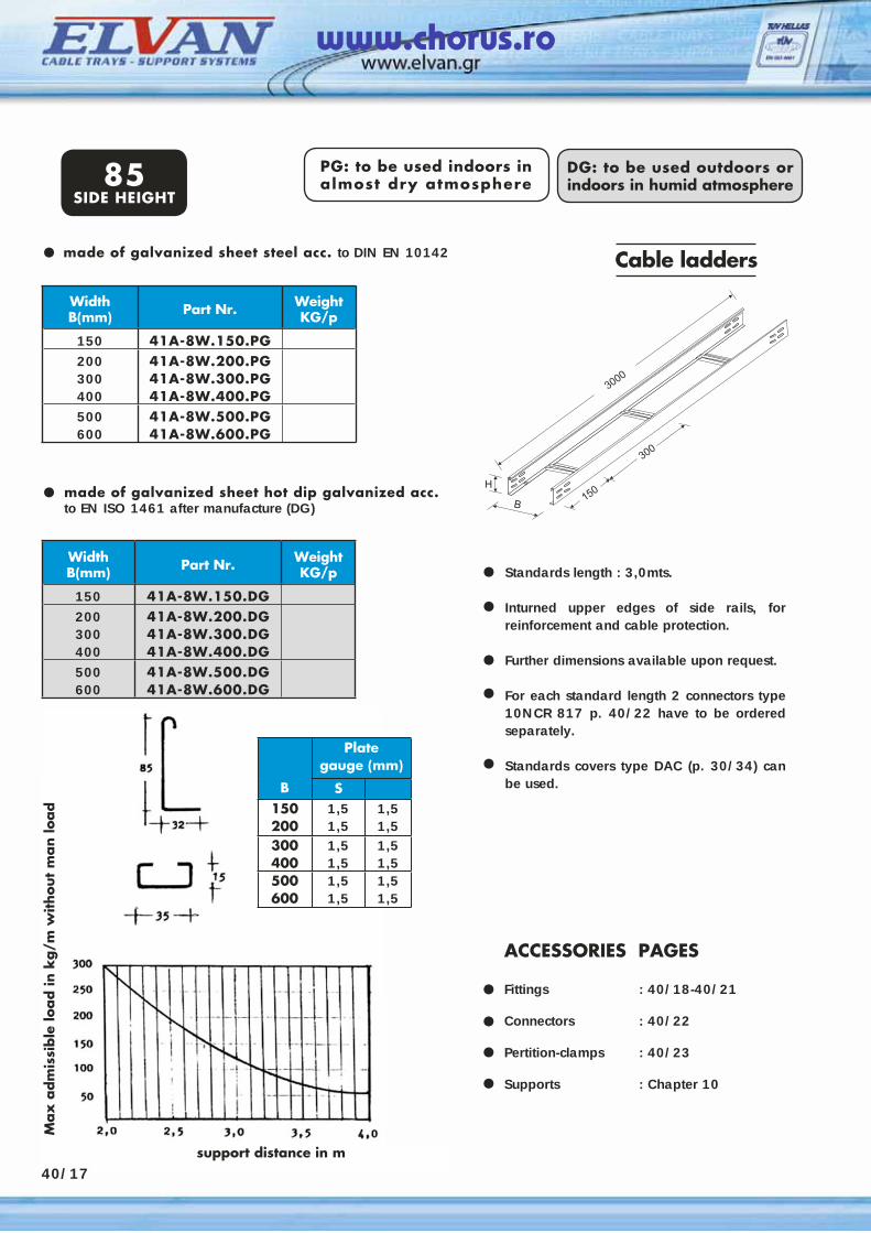
Standards length : 3,0mts.
Inturned upper edges of side rails, for reinforcement and cable protection.
Further dimensions available upon request.
For each standard length 2 connectors type 10NCR 817 p. 40/22 have to be ordered separately.
Standards covers type DAC (p. 30/34) can be used.
Cable ladders
made of galvanized sheet hot dip galvanized acc. to EN ISO 1461 after manufacture (DG)
•
••
••
•
ACCESSORIES PAGES Fittings : 40/18-40/21
Connectors : 40/22
Pertition-clamps : 40/23 Supports : Chapter 10
••••
made of galvanized sheet steel acc. to DIN EN 10142•
PG: to be used indoors in almost dry atmosphere
DG: to be used outdoors or indoors in humid atmosphere85
SIDE HEIGHT
support distance in m
Max
adm
issi
ble
load in
kg/m
without
man lo
ad
WidthΒ(mm) Part Nr. Weight
KG/p
150 41A-8W.150.PG200300400
41A-8W.200.PG41A-8W.300.PG41A-8W.400.PG
500600
41A-8W.500.PG41A-8W.600.PG
WidthΒ(mm) Part Nr. Weight
KG/p
150 41A-8W.150.DG200300400
41A-8W.200.DG41A-8W.300.DG41A-8W.400.DG
500600
41A-8W.500.DG41A-8W.600.DG
Plate gauge (mm)
B S150200
1,51,5
1,51,5
300400
1,51,5
1,51,5
500600
1,51,5
1,51,5
40/17
www.chorus.ro
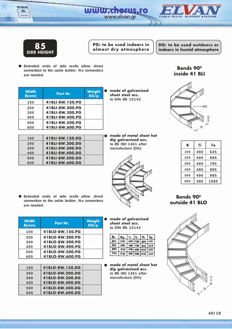
WidthΒ(mm) Part Nr. Weight
KG/p
150 41BLI-8W.150.PG200300400
41BLI-8W.200.PG41BLI-8W.300.PG41BLI-8W.400.PG
500600
41BLI-8W.500.PG41BLI-8W.600.PG
PG: to be used indoors in almost dry atmosphere
DG: to be used outdoors or indoors in humid atmosphere
Extended ends of side walls allow direct connection to the cable ladder. No connectors are needed.
•
•
•
Bends 900
inside 41 BLI
150 41BLI-8W.150.DG200300400
41BLI-8W.200.DG41BLI-8W.300.DG41BLI-8W.400.DG
500600
41BLI-8W.500.DG41BLI-8W.600.DG
WidthΒ(mm) Part Nr. Weight
KG/p
150 41BLΟ-8W.150.PG200300400
41BLΟ-8W.200.PG41BLΟ-8W.300.PG41BLΟ-8W.400.PG
500600
41BLΟ-8W.500.PG41BLΟ-8W.600.PG
•
•
• made of metal sheet hot dip galvanized acc.to EN ISO 1461 after manufacture (DG)
150 41BLΟ-8W.150.DG200300400
41BLΟ-8W.200.DG41BLΟ-8W.300.DG41BLΟ-8W.400.DG
500600
41BLΟ-8W.500.DG41BLΟ-8W.600.DG
made of galvanized sheet steel acc.to DIN EN 10142
Bends 900
outside 41 BLOExtended ends of side walls allow direct connection to the cable ladder. No connectors are needed.
made of galvanized sheet steel acc.to DIN EN 10142
85SIDE HEIGHT
made of metal sheet hot dip galvanized acc.to EN ISO 1461 after manufacture (DG)
40/18
B Γi Γe
150 490 635200 490 685300 490 785
400 490 885500 490 985600 490 1085
www.chorus.ro
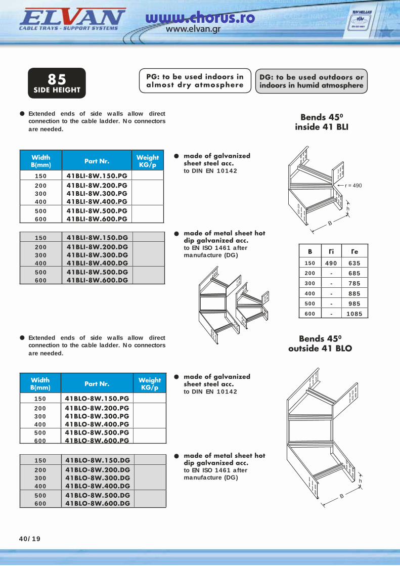
40/19
WidthΒ(mm) Part Nr. Weight
KG/p
150 41BLI-8W.150.PG200300400
41BLI-8W.200.PG41BLI-8W.300.PG41BLI-8W.400.PG
500600
41BLI-8W.500.PG41BLI-8W.600.PG
PG: to be used indoors in almost dry atmosphere
DG: to be used outdoors or indoors in humid atmosphere
Extended ends of side walls allow direct connection to the cable ladder. No connectors are needed.
•
•
•
Bends 450
inside 41 BLI
150 41BLI-8W.150.DG200300400
41BLI-8W.200.DG41BLI-8W.300.DG41BLI-8W.400.DG
500600
41BLI-8W.500.DG41BLI-8W.600.DG
WidthΒ(mm) Part Nr. Weight
KG/p
150 41BLΟ-8W.150.PG200300400
41BLΟ-8W.200.PG41BLΟ-8W.300.PG41BLΟ-8W.400.PG
500600
41BLΟ-8W.500.PG41BLΟ-8W.600.PG
•
•
• made of metal sheet hot dip galvanized acc.to EN ISO 1461 after manufacture (DG)
150 41BLΟ-8W.150.DG200300400
41BLΟ-8W.200.DG41BLΟ-8W.300.DG41BLΟ-8W.400.DG
500600
41BLΟ-8W.500.DG41BLΟ-8W.600.DG
made of galvanized sheet steel acc.to DIN EN 10142
Bends 450
outside 41 BLOExtended ends of side walls allow direct connection to the cable ladder. No connectors are needed.
made of galvanized sheet steel acc.to DIN EN 10142
85SIDE HEIGHT
made of metal sheet hot dip galvanized acc.to EN ISO 1461 after manufacture (DG) B Γi Γe
150 490 635200 - 685300 - 785
400 - 885500 - 985600 - 1085
www.chorus.ro
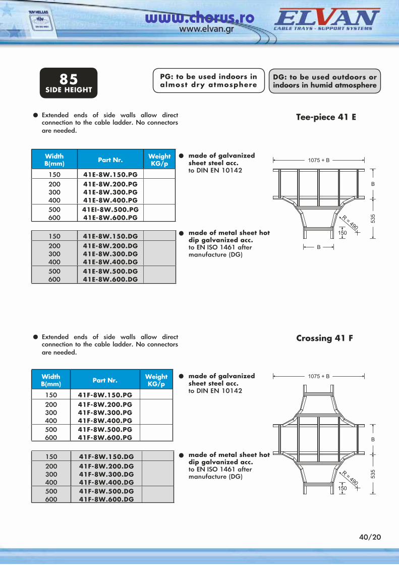
40/20
WidthΒ(mm) Part Nr. Weight
KG/p
150 41E-8W.150.PG200300400
41E-8W.200.PG41E-8W.300.PG41E-8W.400.PG
500600
41EI-8W.500.PG41E-8W.600.PG
PG: to be used indoors in almost dry atmosphere
DG: to be used outdoors or indoors in humid atmosphere
•
•
Tee-piece 41 E
150 41E-8W.150.DG200300400
41E-8W.200.DG41E-8W.300.DG41E-8W.400.DG
500600
41E-8W.500.DG41E-8W.600.DG
WidthΒ(mm) Part Nr. Weight
KG/p
150 41F-8W.150.PG200300400
41F-8W.200.PG41F-8W.300.PG41F-8W.400.PG
500600
41F-8W.500.PG41F-8W.600.PG
•
• made of metal sheet hot dip galvanized acc.to EN ISO 1461 after manufacture (DG)
150 41F-8W.150.DG200300400
41F-8W.200.DG41F-8W.300.DG41F-8W.400.DG
500600
41F-8W.500.DG41F-8W.600.DG
made of galvanized sheet steel acc.to DIN EN 10142
Crossing 41 F
made of metal sheet hot dip galvanized acc.to EN ISO 1461 after manufacture (DG)
made of galvanized sheet steel acc.to DIN EN 10142
85SIDE HEIGHT
Extended ends of side walls allow direct connection to the cable ladder. No connectors are needed.
•
• Extended ends of side walls allow direct connection to the cable ladder. No connectors are needed.
www.chorus.ro
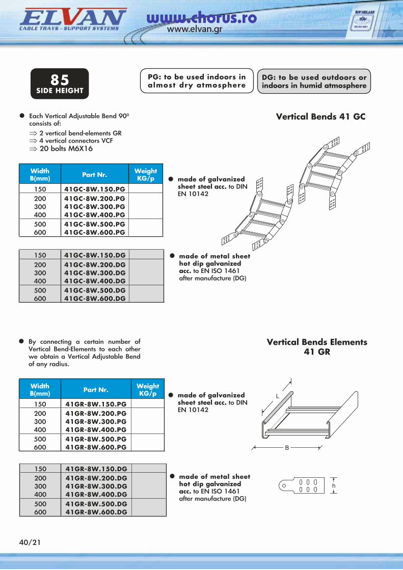
40/21
PG: to be used indoors in almost dry atmosphere
DG: to be used outdoors or indoors in humid atmosphere85
SIDE HEIGHT
150 41GC-8W.150.DG200300400
41GC-8W.200.DG41GC-8W.300.DG41GC-8W.400.DG
500600
41GC-8W.500.DG41GC-8W.600.DG
WidthΒ(mm) Part Nr. Weight
KG/p
150 41GC-8W.150.PG200300400
41GC-8W.200.PG41GC-8W.300.PG41GC-8W.400.PG
500600
41GC-8W.500.PG41GC-8W.600.PG
150 41GR-8W.150.DG200300400
41GR-8W.200.DG41GR-8W.300.DG41GR-8W.400.DG
500600
41GR-8W.500.DG41GR-8W.600.DG
WidthΒ(mm) Part Nr. Weight
KG/p
150 41GR-8W.150.PG200300400
41GR-8W.200.PG41GR-8W.300.PG41GR-8W.400.PG
500600
41GR-8W.500.PG41GR-8W.600.PG
Vertical Bends Elements41 GR
Each Vertical Adjustable Bend 900 consists of:⇒ 2 vertical bend-elements GR⇒ 4 vertical connectors VCF⇒ 20 bolts M6X16
•
•
•
Vertical Bends 41 GC
• made of galvanized sheet steel acc. to DINEN 10142
made of galvanized sheet steel acc. to DINEN 10142
made of metal sheet hot dip galvanized acc. to EN ISO 1461 after manufacture (DG)
By connecting a certain number of Vertical Bend-Elements to each other we obtain a Vertical Adjustable Bend of any radius.
•
• made of metal sheet hot dip galvanized acc. to EN ISO 1461 after manufacture (DG)
www.chorus.ro
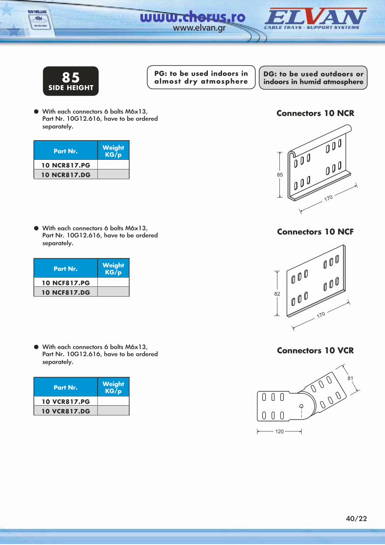
40/22
PG: to be used indoors in almost dry atmosphere
DG: to be used outdoors or indoors in humid atmosphere85
SIDE HEIGHT
With each connectors 6 bolts M6x13, Part Nr. 10G12.616, have to be ordered separately.
•
Part Nr. Weight KG/p
10 NCR817.PG10 NCR817.DG
With each connectors 6 bolts M6x13, Part Nr. 10G12.616, have to be ordered separately.
•
Part Nr. Weight KG/p
10 NCF817.PG10 NCF817.DG
With each connectors 6 bolts M6x13, Part Nr. 10G12.616, have to be ordered separately.
•
Part Nr. Weight KG/p
10 VCR817.PG10 VCR817.DG
Connectors 10 NCR
Connectors 10 NCF
Connectors 10 VCR
www.chorus.ro
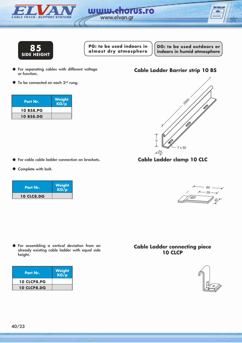
For separating cables with different voltage or function.
To be connected on each 2nd rung.
•
Part Nr. Weight KG/p
10 BS8.PG10 BS8.DG
Cable Ladder Barrier strip 10 BS
•
For cable cable ladder connection on brackets.
Complete with bolt.
•
Part Nr. Weight KG/p
10 CLC8.DG
Cable Ladder clamp 10 CLC
•
For assembling a vertical deviation from an already existing cable ladder with equal side height.
•
Part Nr. Weight KG/p
10 CLCP8.PG10 CLCP8.DG
Cable Ladder connecting piece 10 CLCP
PG: to be used indoors in almost dry atmosphere
DG: to be used outdoors or indoors in humid atmosphere85
SIDE HEIGHT
40/23
www.chorus.ro
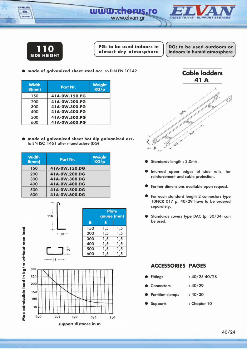
40/24
Standards length : 3,0mts.
Inturned upper edges of side rails, for reinforcement and cable protection.
Further dimensions available upon request.
For each standard length 2 connectors type 10NCR 017 p. 40/29 have to be ordered separately.
Standards covers type DAC (p. 30/34) can be used.
Cable ladders 41 A
made of galvanized sheet hot dip galvanized acc. to EN ISO 1461 after manufacture (DG)
•
••
••
•
ACCESSORIES PAGES Fittings : 40/25-40/28
Connectors : 40/29
Pertition-clamps : 40/30 Supports : Chapter 10
••••
made of galvanized sheet steel acc. to DIN EN 10142•
PG: to be used indoors in almost dry atmosphere
DG: to be used outdoors or indoors in humid atmosphere110
SIDE HEIGHT
Max
adm
issi
ble
load in
kg/m
without
man lo
ad
WidthΒ(mm) Part Nr. Weight
KG/p
150 41A-0W.150.PG200300400
41A-0W.200.PG41A-0W.300.PG41A-0W.400.PG
500600
41A-0W.500.PG41A-0W.600.PG
WidthΒ(mm) Part Nr. Weight
KG/p
150 41A-0W.150.DG200300400
41A-0W.200.DG41A-0W.300.DG41A-0W.400.DG
500600
41A-0W.500.DG41A-0W.600.DG
Plate gauge (mm)
B S150200
1,51,5
1,51,5
300400
1,51,5
1,51,5
500600
1,51,5
1,51,5
support distance in m
www.chorus.ro
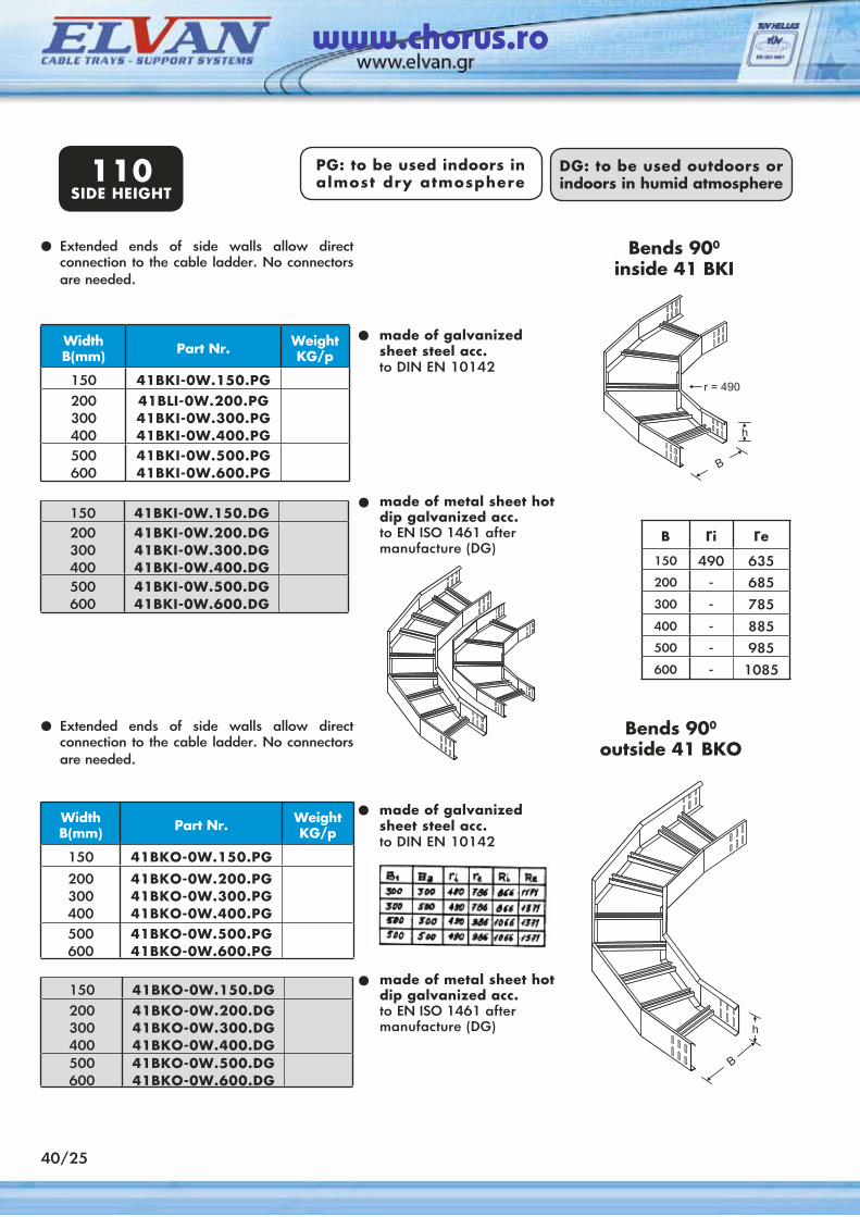
WidthΒ(mm) Part Nr. Weight
KG/p
150 41BKI-0W.150.PG200300400
41BLI-0W.200.PG41BKI-0W.300.PG41BKI-0W.400.PG
500600
41BKI-0W.500.PG41BKI-0W.600.PG
PG: to be used indoors in almost dry atmosphere
DG: to be used outdoors or indoors in humid atmosphere
Extended ends of side walls allow direct connection to the cable ladder. No connectors are needed.
•
•
•
Bends 900
inside 41 BKI
150 41BKI-0W.150.DG200300400
41BKI-0W.200.DG41BKI-0W.300.DG41BKI-0W.400.DG
500600
41BKI-0W.500.DG41BKI-0W.600.DG
WidthΒ(mm) Part Nr. Weight
KG/p
150 41BKΟ-0W.150.PG
200300400
41BKΟ-0W.200.PG41BKΟ-0W.300.PG41BKΟ-0W.400.PG
500600
41BKΟ-0W.500.PG41BKΟ-0W.600.PG
•
•
• made of metal sheet hot dip galvanized acc.to EN ISO 1461 after manufacture (DG)
150 41BKΟ-0W.150.DG200300400
41BKΟ-0W.200.DG41BKΟ-0W.300.DG41BKΟ-0W.400.DG
500600
41BKΟ-0W.500.DG41BKΟ-0W.600.DG
made of galvanized sheet steel acc.to DIN EN 10142
Bends 900
outside 41 BKOExtended ends of side walls allow direct connection to the cable ladder. No connectors are needed.
made of galvanized sheet steel acc.to DIN EN 10142
110SIDE HEIGHT
40/25
B Γi Γe
150 490 635200 - 685300 - 785
400 - 885500 - 985600 - 1085
made of metal sheet hot dip galvanized acc.to EN ISO 1461 after manufacture (DG)
www.chorus.ro
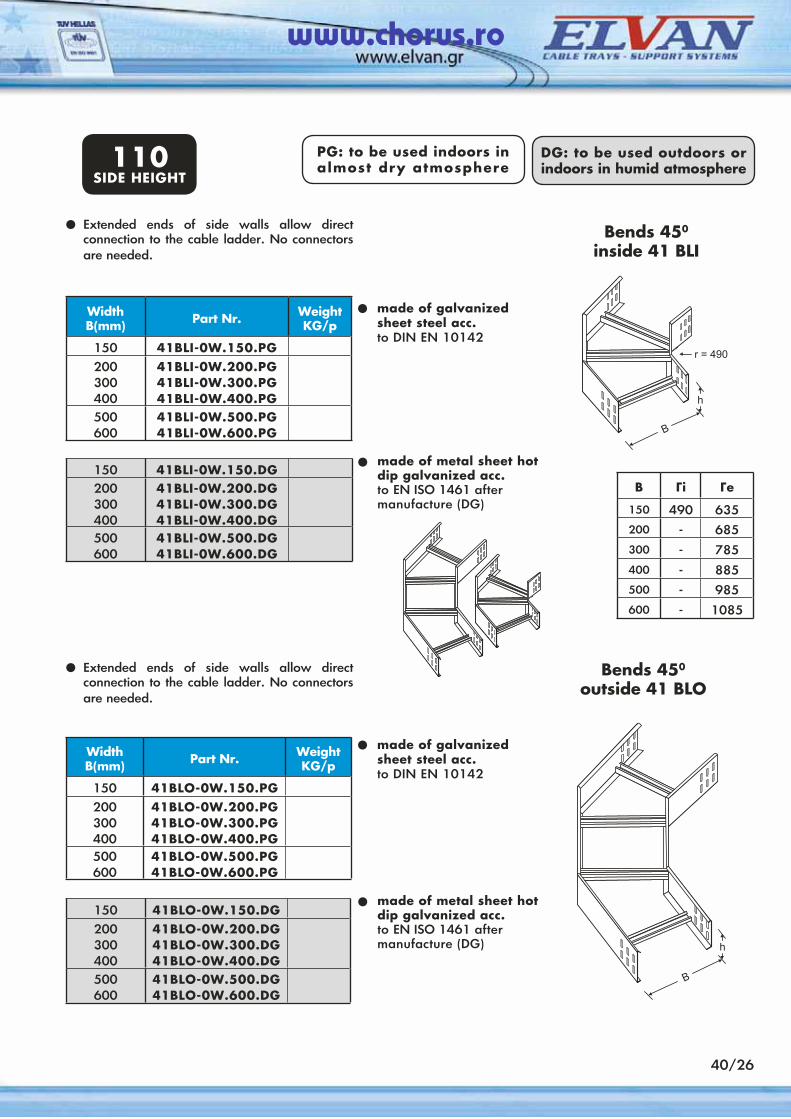
WidthΒ(mm) Part Nr. Weight
KG/p
150 41BLI-0W.150.PG200300400
41BLI-0W.200.PG41BLI-0W.300.PG41BLI-0W.400.PG
500600
41BLI-0W.500.PG41BLI-0W.600.PG
PG: to be used indoors in almost dry atmosphere
DG: to be used outdoors or indoors in humid atmosphere
Extended ends of side walls allow direct connection to the cable ladder. No connectors are needed.
•
•
•
Bends 450
inside 41 BLI
150 41BLI-0W.150.DG200300400
41BLI-0W.200.DG41BLI-0W.300.DG41BLI-0W.400.DG
500600
41BLI-0W.500.DG41BLI-0W.600.DG
WidthΒ(mm) Part Nr. Weight
KG/p
150 41BLΟ-0W.150.PG200300400
41BLΟ-0W.200.PG41BLΟ-0W.300.PG41BLΟ-0W.400.PG
500600
41BLΟ-0W.500.PG41BLΟ-0W.600.PG
•
•
• made of metal sheet hot dip galvanized acc.to EN ISO 1461 after manufacture (DG)
150 41BLΟ-0W.150.DG200300400
41BLΟ-0W.200.DG41BLΟ-0W.300.DG41BLΟ-0W.400.DG
500600
41BLΟ-0W.500.DG41BLΟ-0W.600.DG
made of galvanized sheet steel acc.to DIN EN 10142
Bends 450
outside 41 BLOExtended ends of side walls allow direct connection to the cable ladder. No connectors are needed.
made of galvanized sheet steel acc.to DIN EN 10142
110SIDE HEIGHT
made of metal sheet hot dip galvanized acc.to EN ISO 1461 after manufacture (DG)
40/26
B Γi Γe
150 490 635200 - 685300 - 785
400 - 885500 - 985600 - 1085
www.chorus.ro
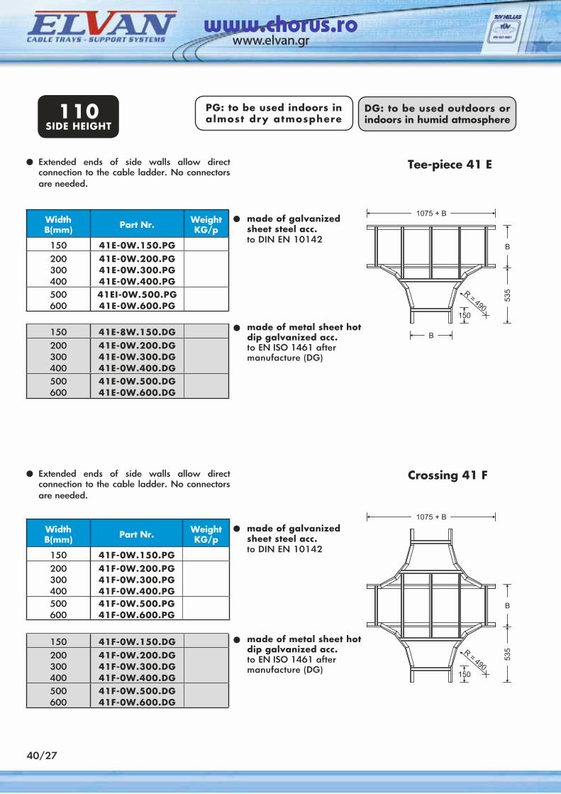
WidthΒ(mm) Part Nr. Weight
KG/p
150 41E-0W.150.PG200300400
41E-0W.200.PG41E-0W.300.PG41E-0W.400.PG
500600
41EI-0W.500.PG41E-0W.600.PG
PG: to be used indoors in almost dry atmosphere
DG: to be used outdoors or indoors in humid atmosphere
Extended ends of side walls allow direct connection to the cable ladder. No connectors are needed.
•
•
•
Tee-piece 41 E
150 41E-8W.150.DG200300400
41E-0W.200.DG41E-0W.300.DG41E-0W.400.DG
500600
41E-0W.500.DG41E-0W.600.DG
WidthΒ(mm) Part Nr. Weight
KG/p
150 41F-0W.150.PG200300400
41F-0W.200.PG41F-0W.300.PG41F-0W.400.PG
500600
41F-0W.500.PG41F-0W.600.PG
•
•
•150 41F-0W.150.DG200300400
41F-0W.200.DG41F-0W.300.DG41F-0W.400.DG
500600
41F-0W.500.DG41F-0W.600.DG
Crossing 41 FExtended ends of side walls allow direct connection to the cable ladder. No connectors are needed.
110SIDE HEIGHT
40/27
made of metal sheet hot dip galvanized acc.to EN ISO 1461 after manufacture (DG)
made of galvanized sheet steel acc.to DIN EN 10142
made of metal sheet hot dip galvanized acc.to EN ISO 1461 after manufacture (DG)
made of galvanized sheet steel acc.to DIN EN 10142
www.chorus.ro
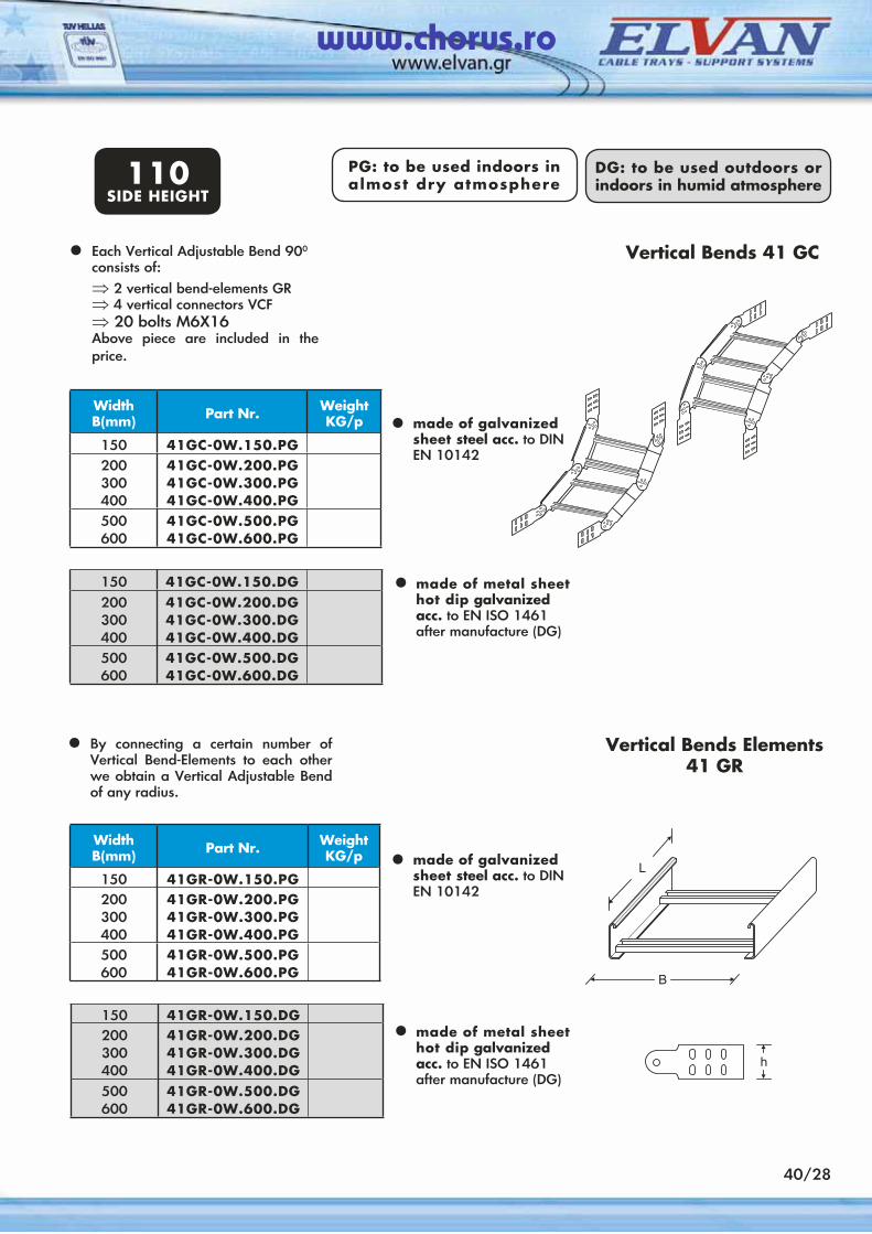
PG: to be used indoors in almost dry atmosphere
DG: to be used outdoors or indoors in humid atmosphere110
SIDE HEIGHT
150 41GC-0W.150.DG200300400
41GC-0W.200.DG41GC-0W.300.DG41GC-0W.400.DG
500600
41GC-0W.500.DG41GC-0W.600.DG
WidthΒ(mm) Part Nr. Weight
KG/p
150 41GC-0W.150.PG200300400
41GC-0W.200.PG41GC-0W.300.PG41GC-0W.400.PG
500600
41GC-0W.500.PG41GC-0W.600.PG
150 41GR-0W.150.DG200300400
41GR-0W.200.DG41GR-0W.300.DG41GR-0W.400.DG
500600
41GR-0W.500.DG41GR-0W.600.DG
WidthΒ(mm) Part Nr. Weight
KG/p
150 41GR-0W.150.PG200300400
41GR-0W.200.PG41GR-0W.300.PG41GR-0W.400.PG
500600
41GR-0W.500.PG41GR-0W.600.PG
Vertical Bends Elements41 GR
Each Vertical Adjustable Bend 900 consists of:⇒ 2 vertical bend-elements GR⇒ 4 vertical connectors VCF⇒ 20 bolts M6X16 Above piece are included in the price.
•
•
•
Vertical Bends 41 GC
• made of galvanized sheet steel acc. to DINEN 10142
made of galvanized sheet steel acc. to DINEN 10142
made of metal sheet hot dip galvanized acc. to EN ISO 1461 after manufacture (DG)
By connecting a certain number of Vertical Bend-Elements to each other we obtain a Vertical Adjustable Bend of any radius.
•
• made of metal sheet hot dip galvanized acc. to EN ISO 1461 after manufacture (DG)
40/28
www.chorus.ro

PG: to be used indoors in almost dry atmosphere
DG: to be used outdoors or indoors in humid atmosphere110
SIDE HEIGHT
With each connectors 6 bolts M6x13, Part Nr. 10G12.616, have to be ordered separately.
•
Part Nr. Weight KG/p
10 NCR017.PG10 NCR017.DG
With each connectors 6 bolts M6x13, Part Nr. 10G12.616, have to be ordered separately.
•
Part Nr. Weight KG/p
10 NCF017.PG10 NCF017.DG
With each connectors 6 bolts M6x13, Part Nr. 10G12.616, have to be ordered separately.
•
Part Nr. Weight KG/p
10 VCR017.PG10 VCR017.DG
Connectors 10 NCR
Connectors 10 NCF
Connectors 10 VCR
40/29
www.chorus.ro
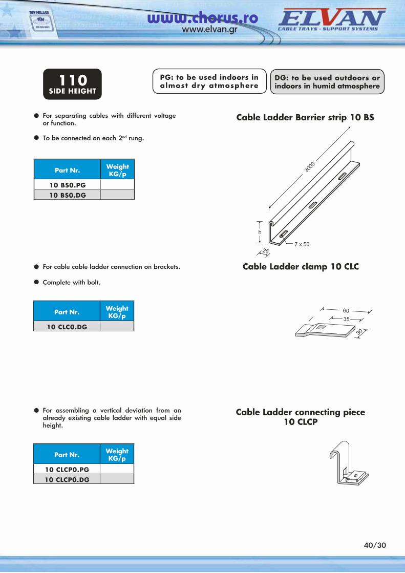
For separating cables with different voltage or function.
To be connected on each 2nd rung.
•
Part Nr. Weight KG/p
10 BS0.PG10 BS0.DG
Cable Ladder Barrier strip 10 BS
•
For cable cable ladder connection on brackets.
Complete with bolt.
•
Part Nr. Weight KG/p
10 CLC0.DG
Cable Ladder clamp 10 CLC
•
For assembling a vertical deviation from an already existing cable ladder with equal side height.
•
Part Nr. Weight KG/p
10 CLCP0.PG10 CLCP0.DG
Cable Ladder connecting piece 10 CLCP
PG: to be used indoors in almost dry atmosphere
DG: to be used outdoors or indoors in humid atmosphere110
SIDE HEIGHT
40/30
www.chorus.ro
General Specifications
ELVORACK system consists of a versatile range of standard components which bolt together to create an unlimited variety of structures and hanging dispositions, used for supporting mechanical or electrical elements.
The advantages of the system are among others:
• easy design and assembly.• numerous services can be provided including
cabling, piping or ducting.• no welding or drilling work is necessary
on site since all components are fully remountable and reusable.
• assembly time is limited to minimum.
The main components of the system are:
• channels (single or multiple sections).• channels nuts.• Fittings and brackets.
Α. The channels are the basic structural member of the system. They can be fixed easily to the floors, ceilings, walls or steelwork and may be connected to each other by using the various fittings available.
ELVORACK channels are formed from 2.5mm pregalvanized steel plate but they are also available in a hot dip galvanized finish. Multiple channel sections are formed by welding together single ones. Standard lengths are 3 mts.
Β. The channel nuts are the elements by which the channels are connected to form the metal framing. They have serrated grooves with hardened teeth which bite securely into the channel’s inturned edges.
They can be inserted easily at any point along the channel and held in place by the spring.
C. Bolts used throughout the ELVORACK sytem are M6, M8, M10, M12 normal bolts and M10, M12 high tensile bolts. The standard finish is zinc plated. Bolts to be used when attaching fittings to the channels are:
• Μ10Χ30 or M12X30 when channels 50A are connected by using fittings of the range 53.
• Μ10Χ25 or Μ12Χ25 when the structure is formed by using channels 50C.
• Μ6Χ25 when attaching the cable tray or cable ladder to a bracket range 10.EHD. Exception is made if trays or ladders are fitted vertically.
In this case the size of bolt should be Μ10Χ25 ή Μ12Χ25.
D. ELVORACK system includes a comprehensive range of fittings, cantilever arms, brackets, pipe clamps etc.
They are also designed to reduce on site cost by avoiding drilling or welding. Fittings are made of 6 mm gauge steel bar.
The size of holes is 14mm in order to accept bolts M10 or M12.
50/01
www.chorus.ro
Design of the Framework
To design a safe structure it is necessary to check all components of the structure. We have therefore to ensure that all channels, fittings and brackets can safely stand the load being imposed upon them.
Α. Channels used as beams
The maximum safe load for a channel used as a beam can be calculated using one of the following three criteria:
1. maximum load calculated from the yield stress of the steel, using a safety factor of 1.5
2. a maximum mid-span deflection 1/180 of the span.
3. a maximum mid-span deflection 1/360 of the span. The maximum uniformly distributed loads according to the above criteria are given on page 50/05.
If in practise loads are neither uniformly distributed across the beam nor a point load the following approximation can be used:
We add all the loads imposed on the channel (uniformly distributed or point loads) and assume that the sum of these loads is imposed at mid-span.
So we can check the beam, using the table on page 50/05 with a safe approximation.
Β. Channels used as upstands
It is rare that that loads are directly applied to the upper end of a channel. In most cases
loads are applied to the brackets or fittings which are connected to the open end of the channel and create a combined axial force down to the upstand and a bending force which reduces the maximum admissible load. Such eccentric loads should be carefully checked in accordance with standard design practice.
C. Brackets
Loads applied to brackets could be either uniformly distributed loads or point loads. In the first case the maximum load applied to a bracket is shown on page 50/20. In the second case the bending moment produced by the various point loads should not exceed the admissible max. bending moment shown below based on a safety factor 1.5.
bracketPart Nr.
max. bendingmoment
10.EHD - 110.EHD - 2
590 Nm or 60 Kgfm1670 Nm or 170 Kgfm
As known the bending moment for any point is obtained by multiplynig the size of the load by the distance from the end of the arm. If several point loads exist the bending moments produced should be added to obtain the total. If on the other hand, part of the load is uniformly distributed along a section of the bracket then this load can be considered as acting at mid-point of the section over which it is spread.
50/02
www.chorus.ro
D. Brackets - Nuts
The admissible loads applied to the various fittings based on a safety factor of 2.5, are shown on page 50/10 of this catalogue. The maximum force to be applied on a nut without sliding across the channel, based on a safety factor 3, is shown on the nearby table:
NutsPart Nr.
Aesistance to slip Put out strength
52 A152 B1
651 Kgf380 Kgf
870 Kgf650 Kgf
If the figure obtained from the calculation exceeds the maximum one shown in the table, then another fitting with 2 or more bolts should be used.
Ε. Bolts
The moment to be applied for tightening bolts Μ10 and Μ12 is 48 Νm (4.7 Kgf) i.e. the one obtained by hand.
The maximum safety load acceptable by a bolt Μ12, when a bending moment of 4.7 Kgfm is applied, amounts to 300Kg.
50/03
www.chorus.ro
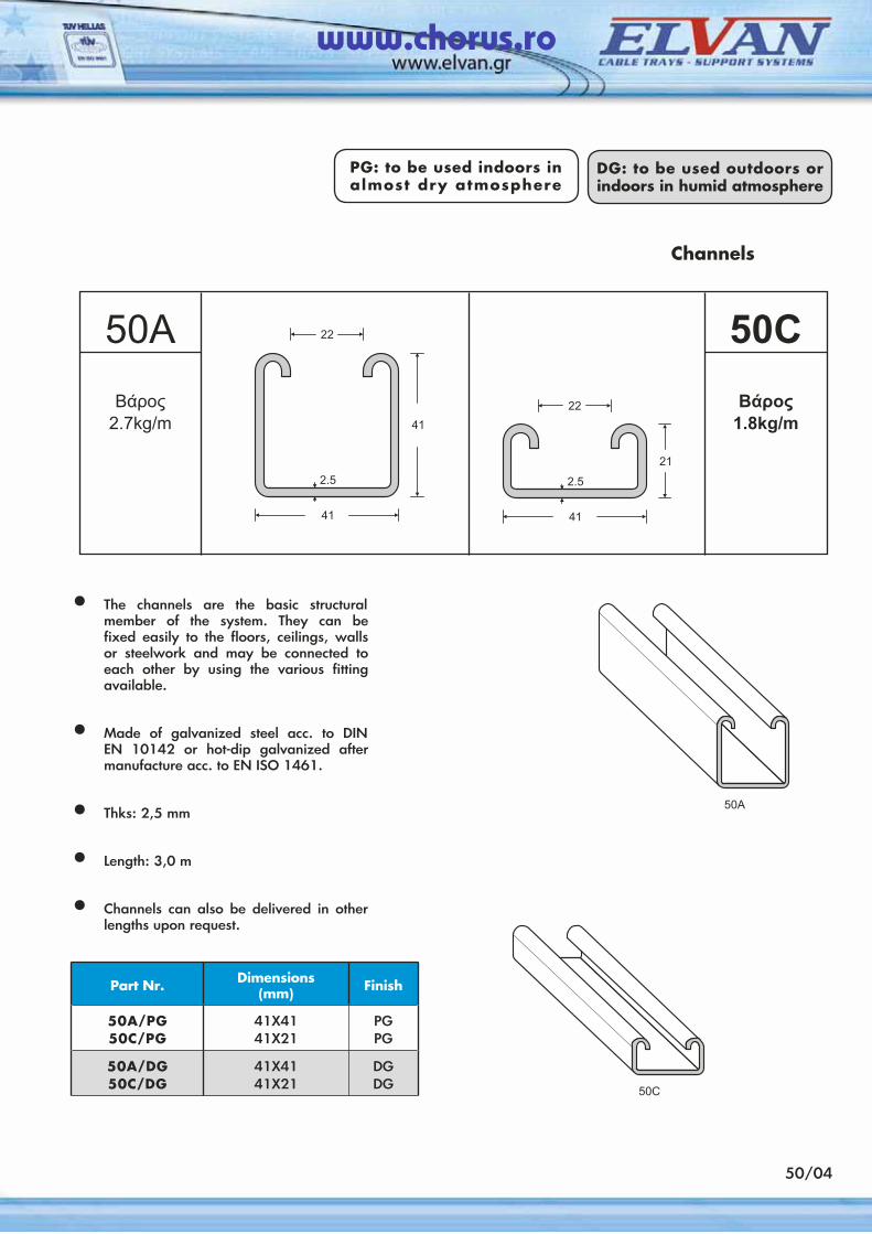
50/04
Part Nr. Dimensions(mm) Finish
50A/PG50C/PG
41X4141X21
PGPG
50A/DG50C/DG
41X4141X21
DGDG
PG: to be used indoors in almost dry atmosphere
DG: to be used outdoors or indoors in humid atmosphere
• The channels are the basic structural member of the system. They can be fixed easily to the floors, ceilings, walls or steelwork and may be connected to each other by using the various fitting available.
• Made of galvanized steel acc. to DIN EN 10142 or hot-dip galvanized after manufacture acc. to EN ISO 1461.
• Thks: 2,5 mm
• Length: 3,0 m
• Channels can also be delivered in other lengths upon request.
Channels
50AΒάρος2.7kg/m
50CΒάρος1.8kg/m
www.chorus.ro
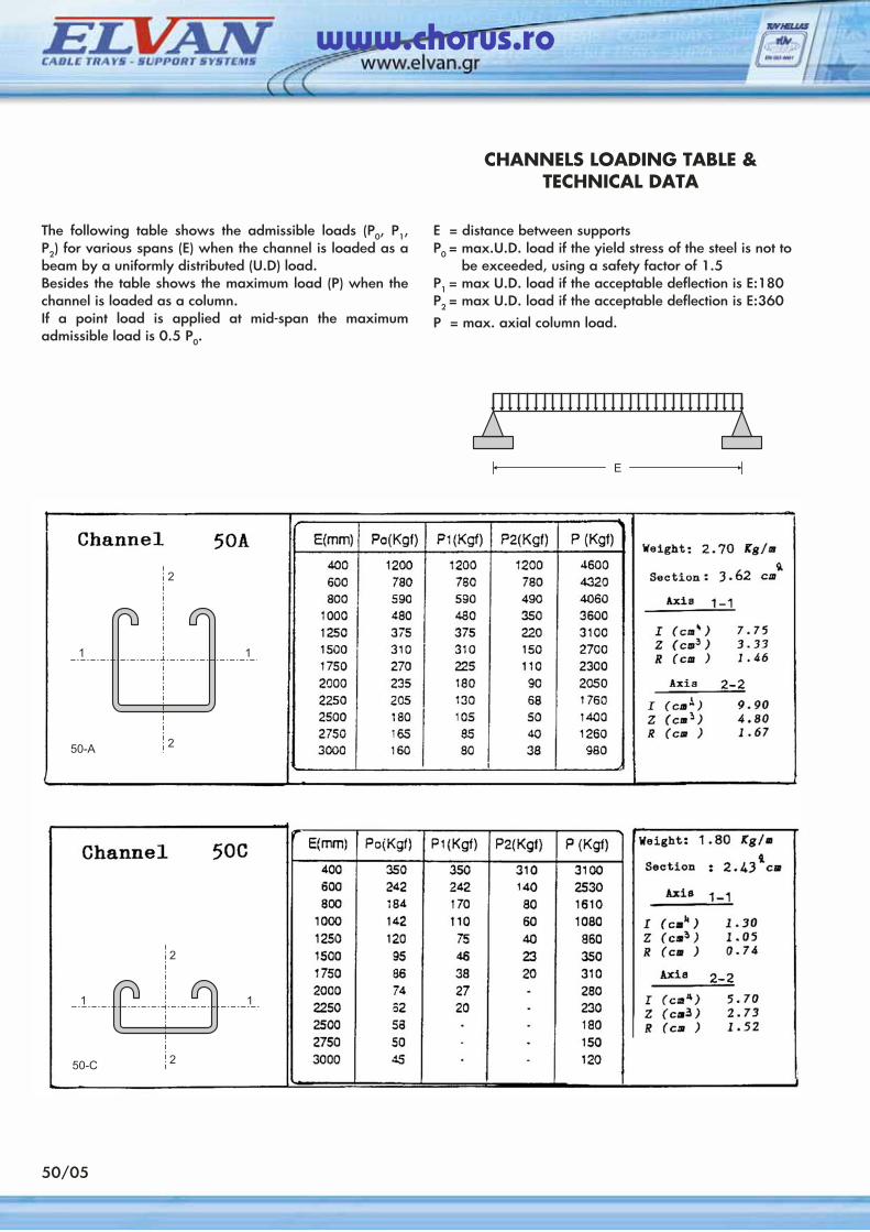
50/05
CHANNELS LOADING TABLE & TECHNICAL DATA
The following table shows the admissible loads (Ρ0, Ρ1, Ρ2) for various spans (Ε) when the channel is loaded as a beam by a uniformly distributed (U.D) load.Besides the table shows the maximum load (P) when the channel is loaded as a column.If a point load is applied at mid-span the maximum admissible load is 0.5 Ρ0.
Ε = distance between supports Ρ0 = max.U.D. load if the yield stress of the steel is not to
be exceeded, using a safety factor of 1.5 Ρ1 = max U.D. load if the acceptable deflection is Ε:180Ρ2 = max U.D. load if the acceptable deflection is Ε:360
Ρ = max. axial column load.
www.chorus.ro
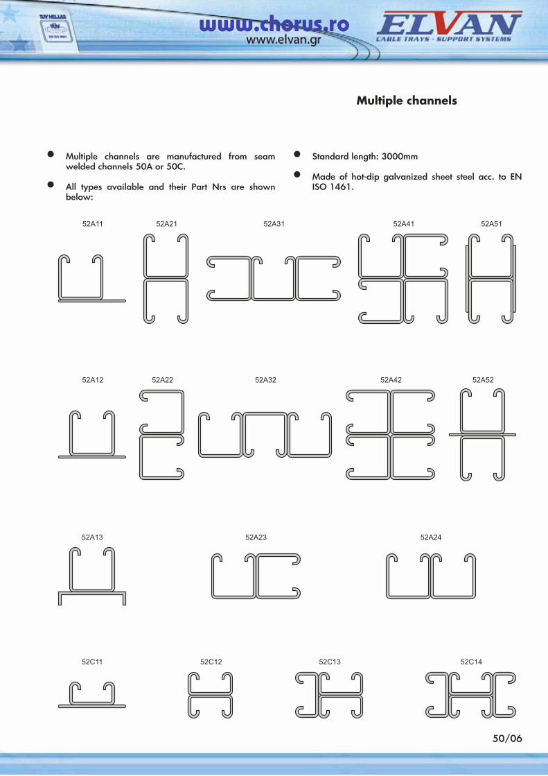
Multiple channels
• Multiple channels are manufactured from seam welded channels 50A or 50C.
• All types available and their Part Nrs are shown below:
• Standard length: 3000mm
• Made of hot-dip galvanized sheet steel acc. to EN ISO 1461.
50/06
www.chorus.ro
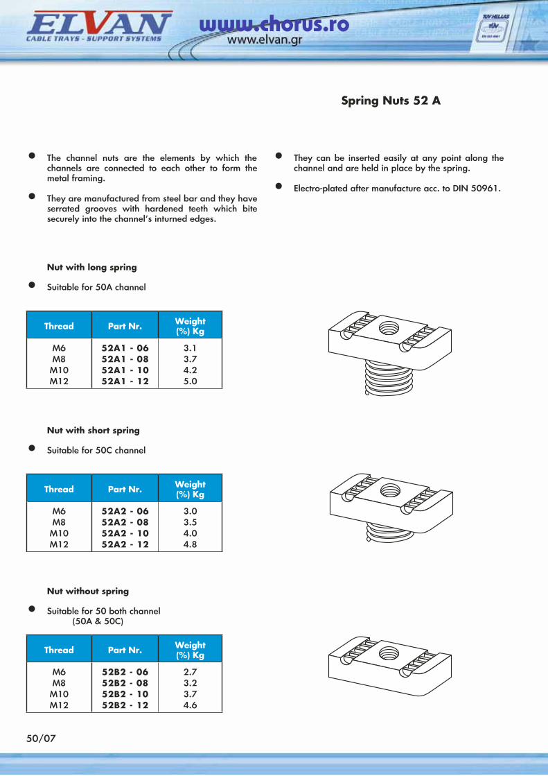
Thread Part Nr. Weight(%) Kg
M6M8
M10M12
52A1 - 0652A1 - 0852A1 - 1052A1 - 12
3.13.74.25.0
Spring Nuts 52 A
• The channel nuts are the elements by which the channels are connected to each other to form the metal framing.
• They are manufactured from steel bar and they have serrated grooves with hardened teeth which bite securely into the channel’s inturned edges.
• They can be inserted easily at any point along the channel and are held in place by the spring.
• Electro-plated after manufacture acc. to DIN 50961.
Nut with long spring
• Suitable for 50A channel
50/07
Thread Part Nr. Weight(%) Kg
M6M8
M10M12
52A2 - 0652A2 - 0852A2 - 1052A2 - 12
3.03.54.04.8
Nut with short spring
• Suitable for 50C channel
Thread Part Nr. Weight(%) Kg
M6M8
M10M12
52B2 - 0652B2 - 0852B2 - 1052B2 - 12
2.73.23.74.6
Nut without spring
• Suitable for 50 both channel (50A & 50C)
www.chorus.ro
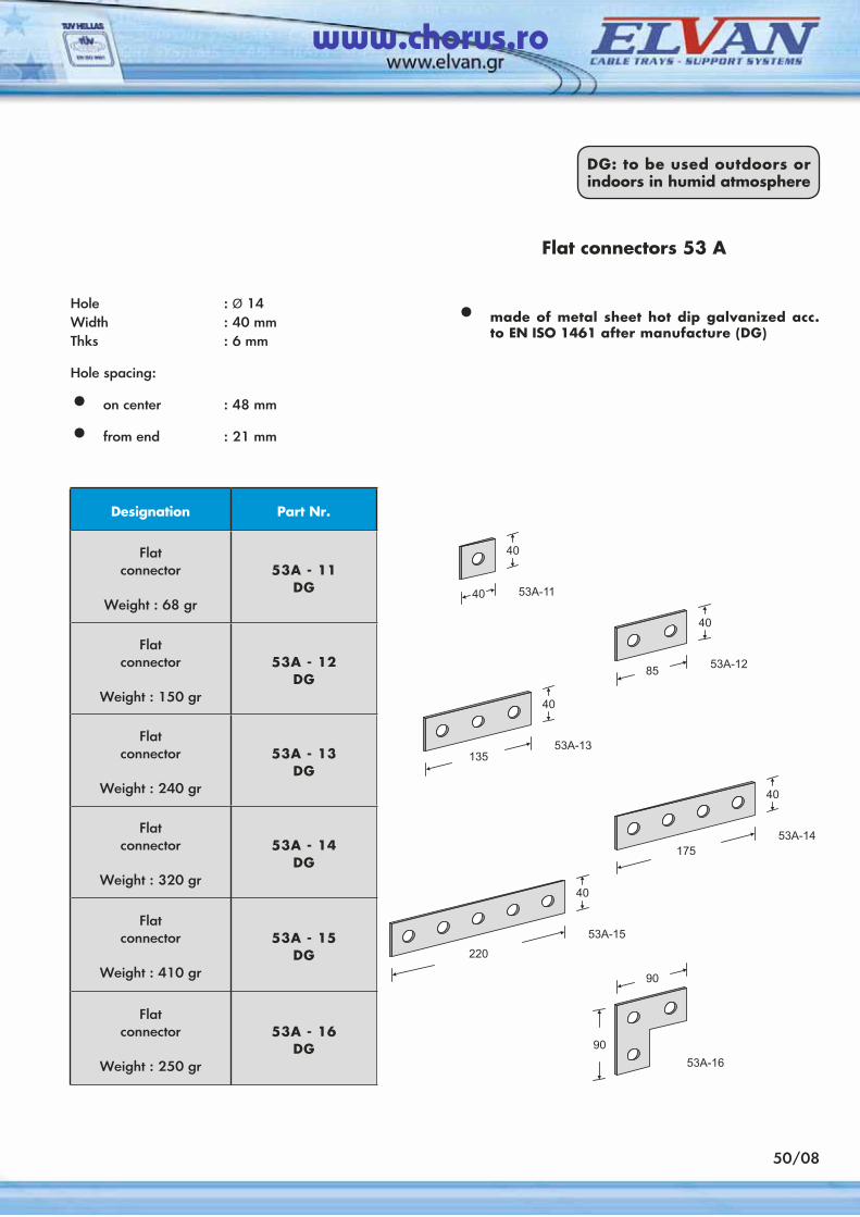
50/08
Designation Part Nr.
Flatconnector
Weight : 68 gr
53A - 11DG
Flatconnector
Weight : 150 gr
53A - 12DG
Flatconnector
Weight : 240 gr
53A - 13DG
Flatconnector
Weight : 320 gr
53A - 14DG
Flatconnector
Weight : 410 gr
53A - 15DG
Flatconnector
Weight : 250 gr
53A - 16DG
Flat connectors 53 A
Hole : Ø 14Width : 40 mmThks : 6 mm
Hole spacing:
• on center : 48 mm
• from end : 21 mm
• made of metal sheet hot dip galvanized acc. to EN ISO 1461 after manufacture (DG)
DG: to be used outdoors or indoors in humid atmosphere
www.chorus.ro
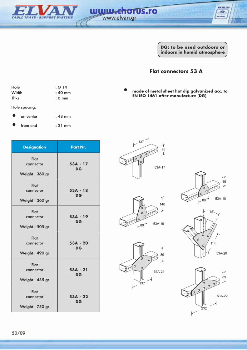
50/09
Designation Part Nr.
Flatconnector
Weight : 360 gr
53A - 17DG
Flatconnector
Weight : 360 gr
53A - 18DG
Flatconnector
Weight : 505 gr
53A - 19DG
Flatconnector
Weight : 490 gr
53A - 20DG
Flatconnector
Weight : 435 gr
53A - 21DG
Flatconnector
Weight : 750 gr
53A - 22DG
Flat connectors 53 A
Hole : Ø 14Width : 40 mmThks : 6 mm
Hole spacing:
• on center : 48 mm
• from end : 21 mm
• made of metal sheet hot dip galvanized acc. to EN ISO 1461 after manufacture (DG)
DG: to be used outdoors or indoors in humid atmosphere
www.chorus.ro
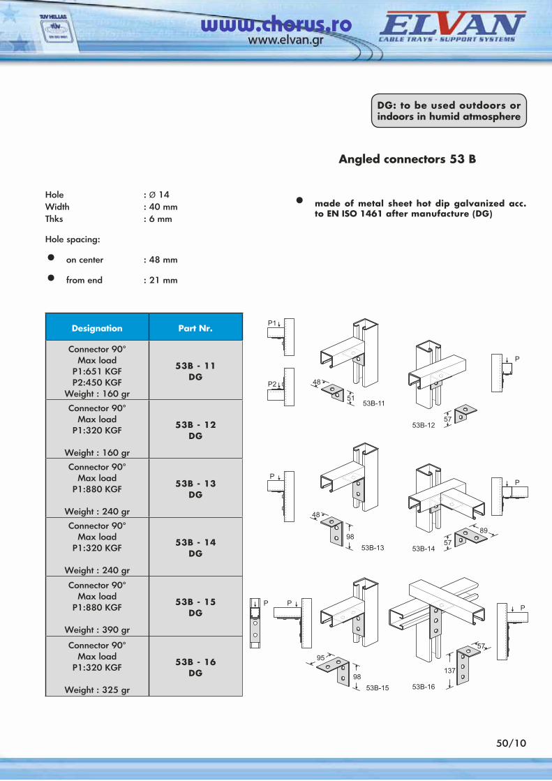
Designation Part Nr.
Connector 90°Max load
P1:651 KGFP2:450 KGF
Weight : 160 gr
53B - 11DG
Connector 90°Max load
P1:320 KGF
Weight : 160 gr
53B - 12DG
Connector 90°Max load
P1:880 KGF
Weight : 240 gr
53B - 13DG
Connector 90°Max load
P1:320 KGF
Weight : 240 gr
53B - 14DG
Connector 90°Max load
P1:880 KGF
Weight : 390 gr
53B - 15DG
Connector 90°Max load
P1:320 KGF
Weight : 325 gr
53B - 16DG
Angled connectors 53 Β
Hole : Ø 14Width : 40 mmThks : 6 mm
Hole spacing:
• on center : 48 mm
• from end : 21 mm
• made of metal sheet hot dip galvanized acc. to EN ISO 1461 after manufacture (DG)
DG: to be used outdoors or indoors in humid atmosphere
50/10
www.chorus.ro
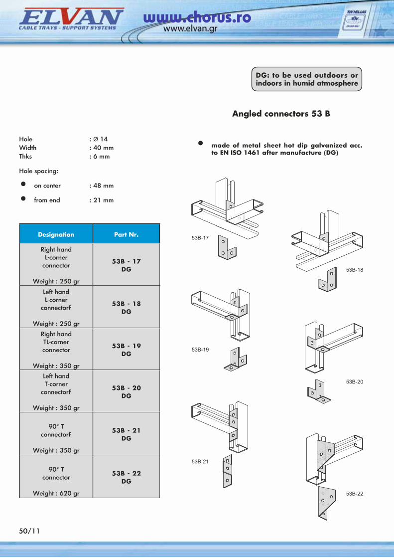
50/11
Designation Part Nr.
Right handL-corner
connector
Weight : 250 gr
53B - 17DG
Left handL-corner
connectorF
Weight : 250 gr
53B - 18DG
Right handTL-cornerconnector
Weight : 350 gr
53B - 19DG
Left handT-corner
connectorF
Weight : 350 gr
53B - 20DG
90° TconnectorF
Weight : 350 gr
53B - 21DG
90° Tconnector
Weight : 620 gr
53B - 22DG
Angled connectors 53 Β
Hole : Ø 14Width : 40 mmThks : 6 mm
Hole spacing:
• on center : 48 mm
• from end : 21 mm
• made of metal sheet hot dip galvanized acc. to EN ISO 1461 after manufacture (DG)
DG: to be used outdoors or indoors in humid atmosphere
www.chorus.ro
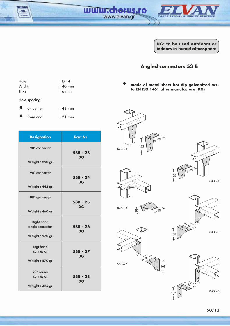
Designation Part Nr.
90° connector
Weight : 650 gr
53B - 23DG
90° connector
Weight : 445 gr
53B - 24DG
90° connector
Weight : 460 gr
53B - 25DG
Right handangle connector
Weight : 570 gr
53B - 26DG
Legt-handconnector
Weight : 570 gr
53B - 27DG
90° cornerconnector
Weight : 325 gr
53B - 28DG
Angled connectors 53 Β
Hole : Ø 14Width : 40 mmThks : 6 mm
Hole spacing:
• on center : 48 mm
• from end : 21 mm
• made of metal sheet hot dip galvanized acc. to EN ISO 1461 after manufacture (DG)
DG: to be used outdoors or indoors in humid atmosphere
50/12
www.chorus.ro
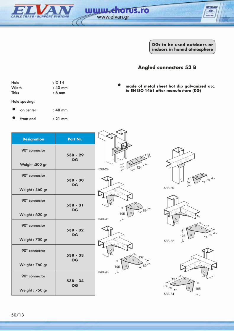
Designation Part Nr.
90° connector
Weight :500 gr
53B - 29DG
90° connector
Weight : 360 gr
53B - 30DG
90° connector
Weight : 620 gr
53B - 31DG
90° connector
Weight : 750 gr
53B - 32DG
90° connector
Weight : 760 gr
53B - 33DG
90° connector
Weight : 750 gr
53B - 34DG
Angled connectors 53 Β
Hole : Ø 14Width : 40 mmThks : 6 mm
Hole spacing:
• on center : 48 mm
• from end : 21 mm
• made of metal sheet hot dip galvanized acc. to EN ISO 1461 after manufacture (DG)
DG: to be used outdoors or indoors in humid atmosphere
50/13
www.chorus.ro
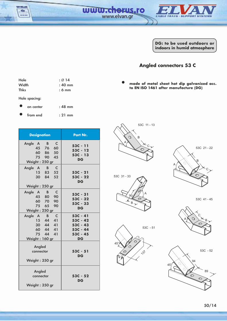
Designation Part Nr.
Angle A B C 45 76 60 60 86 50 75 90 45 Weight : 250 gr
53C - 1153C - 1253C - 13
DG
Angle A B C 15 83 52 30 84 52 Weight : 250 gr
53C - 2153C - 22
DG
Angle A B C 45 80 90 60 70 90 75 65 90 Weight : 250 gr
53C - 3153C - 3253C - 33
DG
Angle A B C 15 44 41 30 44 41 60 44 41 75 44 41 Weight : 160 gr
53C - 4153C - 4253C - 4353C - 4453C - 45
DG
Angledconnector
Weight : 350 gr
53C - 51DG
Angled connector
Weight : 350 gr
53C - 52DG
Angled connectors 53 C
Hole : Ø 14Width : 40 mmThks : 6 mm
Hole spacing:
• on center : 48 mm
• from end : 21 mm
• made of metal sheet hot dip galvanized acc. to EN ISO 1461 after manufacture (DG)
DG: to be used outdoors or indoors in humid atmosphere
50/14
www.chorus.ro
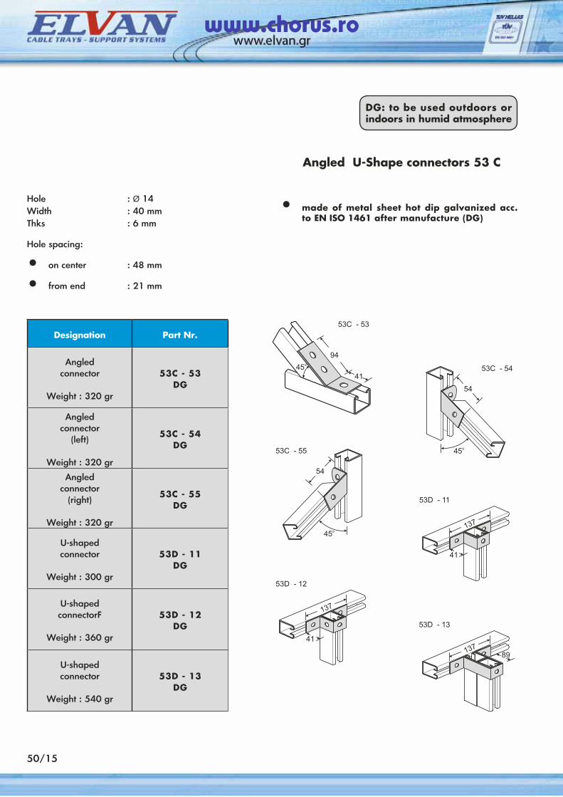
Designation Part Nr.
Angledconnector
Weight : 320 gr
53C - 53DG
Angledconnector
(left)
Weight : 320 gr
53C - 54DG
Angledconnector
(right)
Weight : 320 gr
53C - 55DG
U-shapedconnector
Weight : 300 gr
53D - 11DG
U-shapedconnectorF
Weight : 360 gr
53D - 12DG
U-shapedconnector
Weight : 540 gr
53D - 13DG
Angled U-Shape connectors 53 C
Hole : Ø 14Width : 40 mmThks : 6 mm
Hole spacing:
• on center : 48 mm
• from end : 21 mm
• made of metal sheet hot dip galvanized acc. to EN ISO 1461 after manufacture (DG)
DG: to be used outdoors or indoors in humid atmosphere
50/15
www.chorus.ro
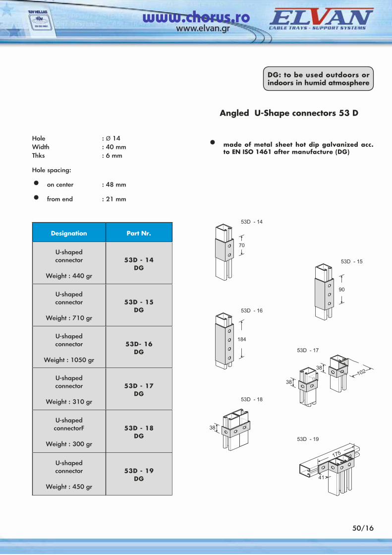
Designation Part Nr.
U-shapedconnector
Weight : 440 gr
53D - 14DG
U-shapedconnector
Weight : 710 gr
53D - 15DG
U-shapedconnector
Weight : 1050 gr
53D- 16DG
U-shapedconnector
Weight : 310 gr
53D - 17DG
U-shapedconnectorF
Weight : 300 gr
53D - 18DG
U-shapedconnector
Weight : 450 gr
53D - 19DG
Angled U-Shape connectors 53 D
Hole : Ø 14Width : 40 mmThks : 6 mm
Hole spacing:
• on center : 48 mm
• from end : 21 mm
• made of metal sheet hot dip galvanized acc. to EN ISO 1461 after manufacture (DG)
DG: to be used outdoors or indoors in humid atmosphere
50/16
www.chorus.ro
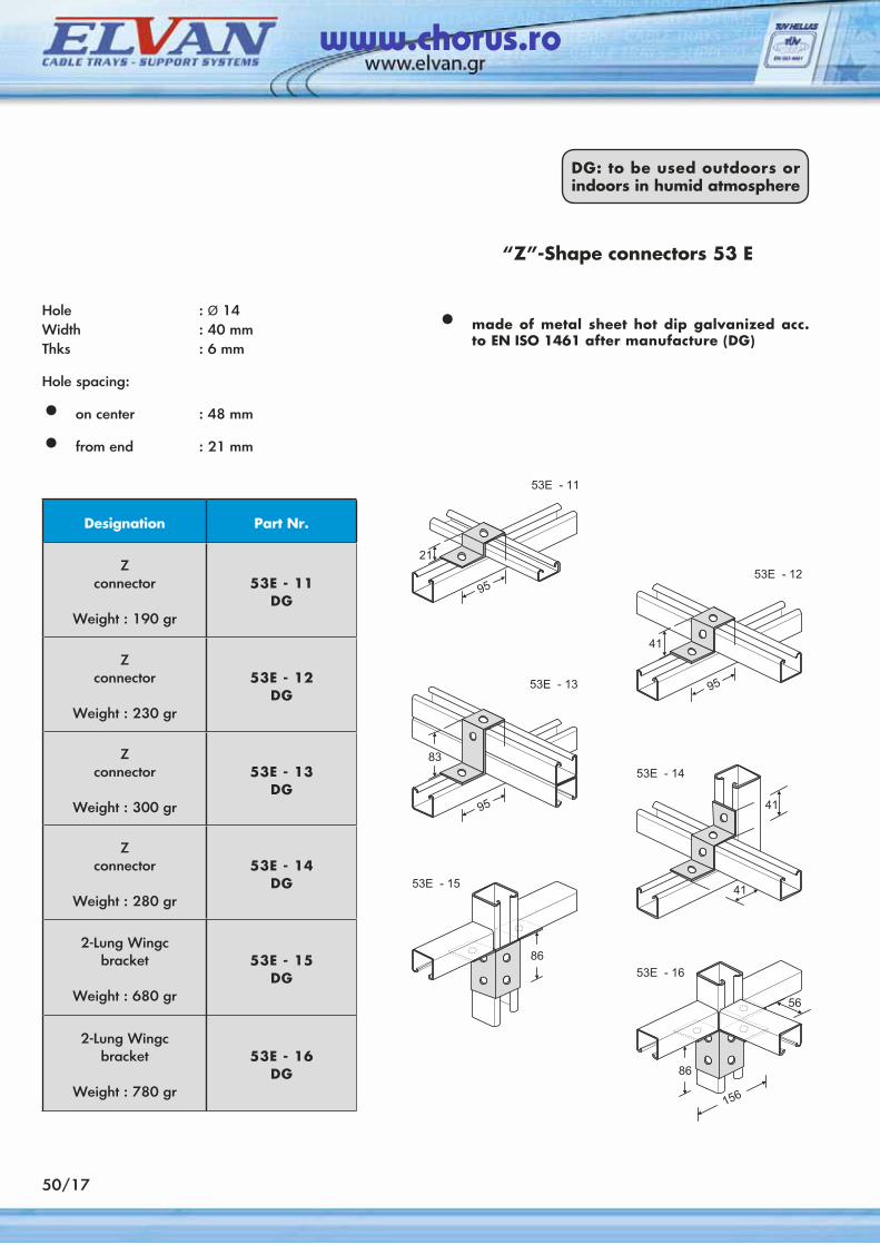
50/17
Designation Part Nr.
Zconnector
Weight : 190 gr
53E - 11DG
Zconnector
Weight : 230 gr
53E - 12DG
Zconnector
Weight : 300 gr
53E - 13DG
Zconnector
Weight : 280 gr
53E - 14DG
2-Lung Wingcbracket
Weight : 680 gr
53E - 15DG
2-Lung Wingcbracket
Weight : 780 gr
53E - 16DG
“Z”-Shape connectors 53 E
Hole : Ø 14Width : 40 mmThks : 6 mm
Hole spacing:
• on center : 48 mm
• from end : 21 mm
• made of metal sheet hot dip galvanized acc. to EN ISO 1461 after manufacture (DG)
DG: to be used outdoors or indoors in humid atmosphere
www.chorus.ro
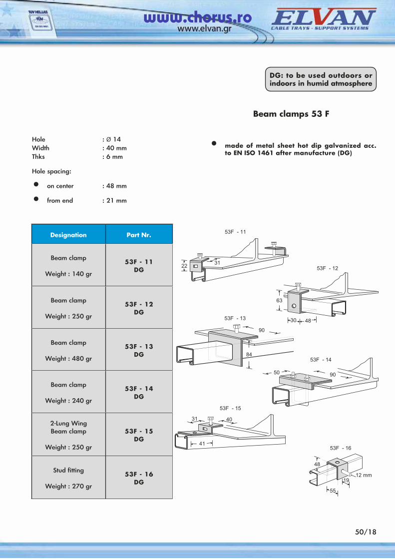
Designation Part Nr.
Beam clamp
Weight : 140 gr
53F - 11DG
Beam clamp
Weight : 250 gr
53F - 12DG
Beam clamp
Weight : 480 gr
53F - 13DG
Beam clamp
Weight : 240 gr
53F - 14DG
2-Lung WingBeam clamp
Weight : 250 gr
53F - 15DG
Stud fitting
Weight : 270 gr
53F - 16DG
Beam clamps 53 F
Hole : Ø 14Width : 40 mmThks : 6 mm
Hole spacing:
• on center : 48 mm
• from end : 21 mm
• made of metal sheet hot dip galvanized acc. to EN ISO 1461 after manufacture (DG)
DG: to be used outdoors or indoors in humid atmosphere
50/18
www.chorus.ro
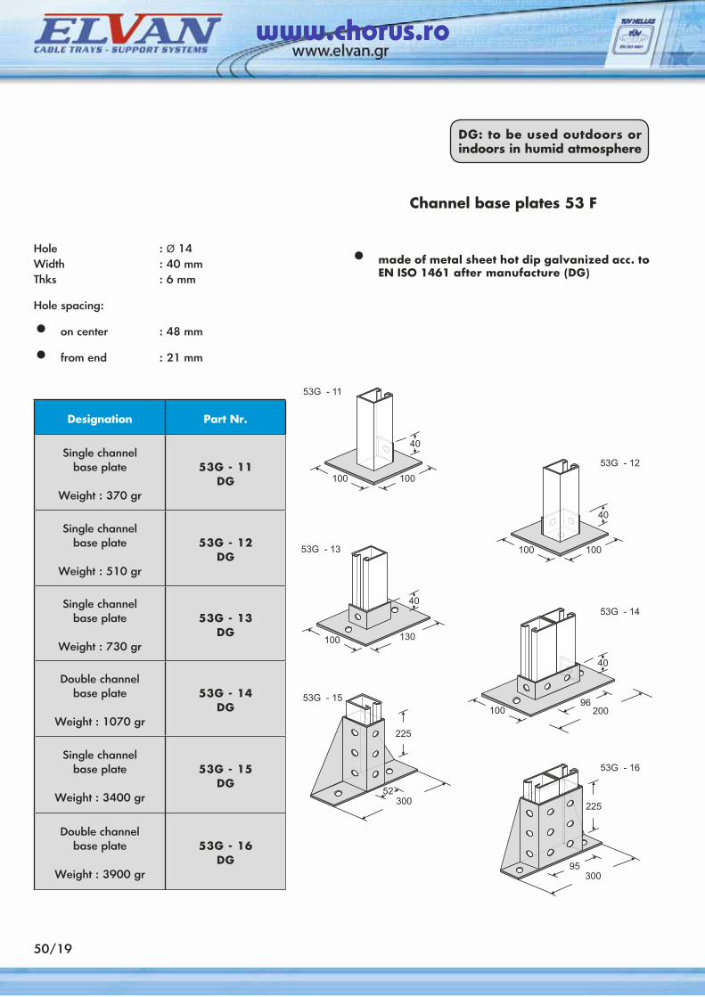
Designation Part Nr.
Single channelbase plate
Weight : 370 gr
53G - 11DG
Single channelbase plate
Weight : 510 gr
53G - 12DG
Single channelbase plate
Weight : 730 gr
53G - 13DG
Double channelbase plate
Weight : 1070 gr
53G - 14DG
Single channelbase plate
Weight : 3400 gr
53G - 15DG
Double channelbase plate
Weight : 3900 gr
53G - 16DG
Channel base plates 53 F
Hole : Ø 14Width : 40 mmThks : 6 mm
Hole spacing:
• on center : 48 mm
• from end : 21 mm
• made of metal sheet hot dip galvanized acc. to EN ISO 1461 after manufacture (DG)
DG: to be used outdoors or indoors in humid atmosphere
50/19
www.chorus.ro
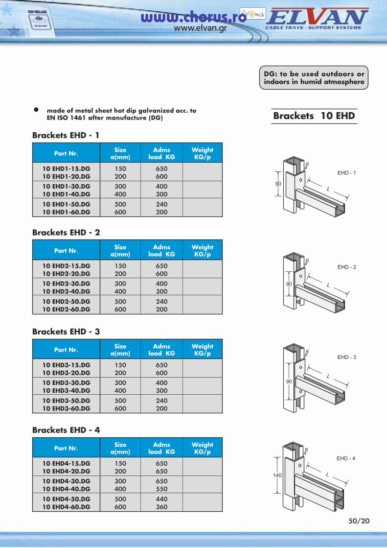
50/20
• made of metal sheet hot dip galvanized acc. to EN ISO 1461 after manufacture (DG)
DG: to be used outdoors or indoors in humid atmosphere
Brackets EHD - 1
Part Nr. Sizea(mm)
Admsload KG
WeightKG/p
10 ΕHD1-15.DG10 EHD1-20.DG
150200
650600
10 EHD1-30.DG10 EHD1-40.DG
300400
400300
10 EHD1-50.DG10 EHD1-60.DG
500600
240200
Brackets 10 EHD
Brackets EHD - 2
Part Nr. Sizea(mm)
Admsload KG
WeightKG/p
10 ΕHD2-15.DG10 EHD2-20.DG
150200
650600
10 EHD2-30.DG10 EHD2-40.DG
300400
400300
10 EHD2-50.DG10 EHD2-60.DG
500600
240200
Brackets EHD - 3
Part Nr. Sizea(mm)
Admsload KG
WeightKG/p
10 ΕHD3-15.DG10 EHD3-20.DG
150200
650600
10 EHD3-30.DG10 EHD3-40.DG
300400
400300
10 EHD3-50.DG10 EHD3-60.DG
500600
240200
Brackets EHD - 4
Part Nr. Sizea(mm)
Admsload KG
WeightKG/p
10 ΕHD4-15.DG10 EHD4-20.DG
150200
650650
10 EHD4-30.DG10 EHD4-40.DG
300400
650550
10 EHD4-50.DG10 EHD4-60.DG
500600
440360
www.chorus.ro
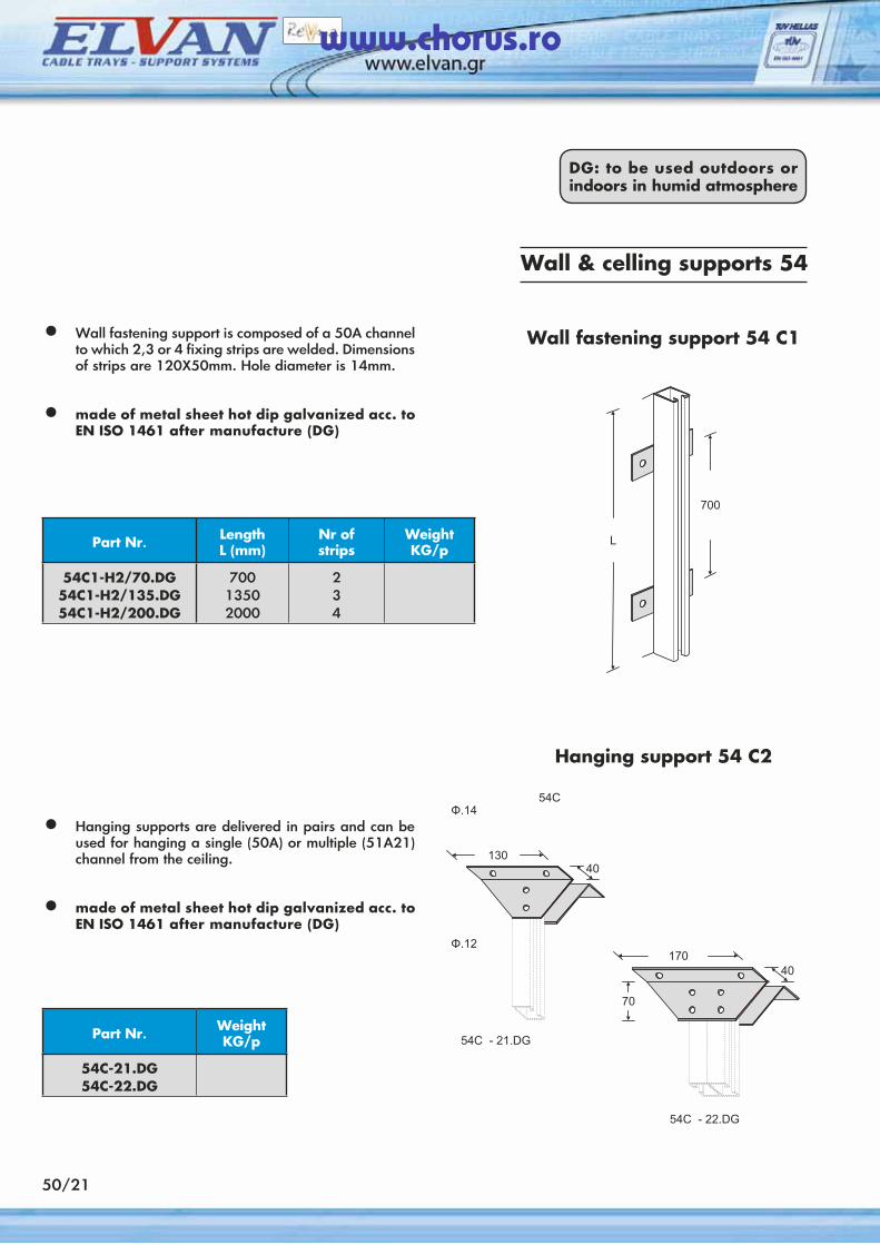
50/21
• Wall fastening support is composed of a 50A channel to which 2,3 or 4 fixing strips are welded. Dimensions of strips are 120X50mm. Hole diameter is 14mm.
• made of metal sheet hot dip galvanized acc. to EN ISO 1461 after manufacture (DG)
DG: to be used outdoors or indoors in humid atmosphere
Wall fastening support 54 C1
Part Nr. LengthL (mm)
Nr ofstrips
WeightKG/p
54C1-H2/70.DG54C1-H2/135.DG54C1-H2/200.DG
70013502000
234
Wall & celling supports 54
• Hanging supports are delivered in pairs and can be used for hanging a single (50A) or multiple (51A21) channel from the ceiling.
• made of metal sheet hot dip galvanized acc. to EN ISO 1461 after manufacture (DG)
Part Nr. WeightKG/p
54C-21.DG54C-22.DG
Hanging support 54 C2
www.chorus.ro
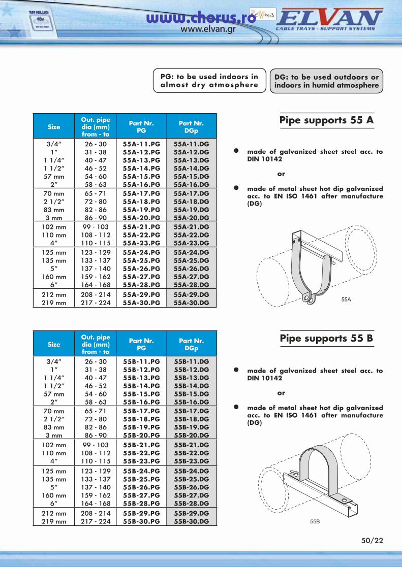
DG: to be used outdoors or indoors in humid atmosphere
PG: to be used indoors in almost dry atmosphere
SizeOut. pipedia (mm)from - to
Part Nr.PG
Part Nr.DGp
3/4”1”
1 1/4”1 1/2”57 mm
2”
26 - 3031 - 3840 - 4746 - 5254 - 6058 - 63
55A-11.PG55A-12.PG55A-13.PG55A-14.PG55A-15.PG55A-16.PG
55A-11.DG55A-12.DG55A-13.DG55A-14.DG55A-15.DG55A-16.DG
70 mm2 1/2”83 mm3 mm
65 - 7172 - 8082 - 8686 - 90
55A-17.PG55A-18.PG55A-19.PG55A-20.PG
55A-17.DG55A-18.DG55A-19.DG55A-20.DG
102 mm110 mm
4”
99 - 103108 - 112110 - 115
55A-21.PG55A-22.PG55A-23.PG
55A-21.DG55A-22.DG55A-23.DG
125 mm135 mm
5”160 mm
6”
123 - 129133 - 137137 - 140159 - 162164 - 168
55A-24.PG55A-25.PG55A-26.PG55A-27.PG55A-28.PG
55A-24.DG55A-25.DG55A-26.DG55A-27.DG55A-28.DG
212 mm219 mm
208 - 214217 - 224
55A-29.PG55A-30.PG
55A-29.DG55A-30.DG
Pipe supports 55 A
• made of galvanized sheet steel acc. to DIN 10142
or
• made of metal sheet hot dip galvanized acc. to EN ISO 1461 after manufacture (DG)
SizeOut. pipedia (mm)from - to
Part Nr.PG
Part Nr.DGp
3/4”1”
1 1/4”1 1/2”57 mm
2”
26 - 3031 - 3840 - 4746 - 5254 - 6058 - 63
55B-11.PG55B-12.PG55B-13.PG55B-14.PG55B-15.PG55B-16.PG
55B-11.DG55B-12.DG55B-13.DG55B-14.DG55B-15.DG55B-16.DG
70 mm2 1/2”83 mm3 mm
65 - 7172 - 8082 - 8686 - 90
55B-17.PG55B-18.PG55B-19.PG55B-20.PG
55B-17.DG55B-18.DG55B-19.DG55B-20.DG
102 mm110 mm
4”
99 - 103108 - 112110 - 115
55B-21.PG55B-22.PG55B-23.PG
55B-21.DG55B-22.DG55B-23.DG
125 mm135 mm
5”160 mm
6”
123 - 129133 - 137137 - 140159 - 162164 - 168
55B-24.PG55B-25.PG55B-26.PG55B-27.PG55B-28.PG
55B-24.DG55B-25.DG55B-26.DG55B-27.DG55B-28.DG
212 mm219 mm
208 - 214217 - 224
55B-29.PG55B-30.PG
55B-29.DG55B-30.DG
Pipe supports 55 B
• made of galvanized sheet steel acc. to DIN 10142
or
• made of metal sheet hot dip galvanized acc. to EN ISO 1461 after manufacture (DG)
50/22
www.chorus.ro
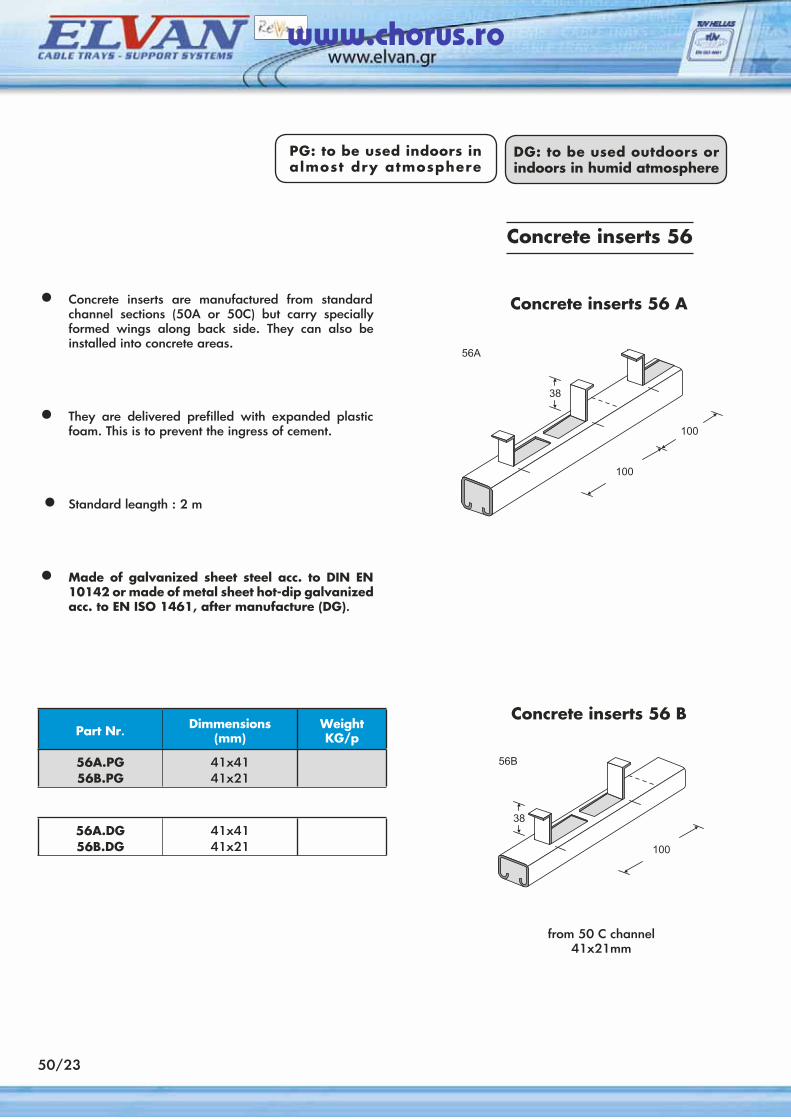
• Concrete inserts are manufactured from standard channel sections (50A or 50C) but carry specially formed wings along back side. They can also be installed into concrete areas.
• They are delivered prefilled with expanded plastic foam. This is to prevent the ingress of cement.
• Standard leangth : 2 m
• Made of galvanized sheet steel acc. to DIN EN 10142 or made of metal sheet hot-dip galvanized acc. to EN ISO 1461, after manufacture (DG).
Concrete inserts 56 A
Concrete inserts 56
Part Nr. Dimmensions(mm)
WeightKG/p
56A.PG56B.PG
41x4141x21
DG: to be used outdoors or indoors in humid atmosphere
PG: to be used indoors in almost dry atmosphere
56A.DG56B.DG
41x4141x21
Concrete inserts 56 Β
from 50 C channel41x21mm
50/23
www.chorus.ro

Application of the ELVORACK system
50/24
www.chorus.ro
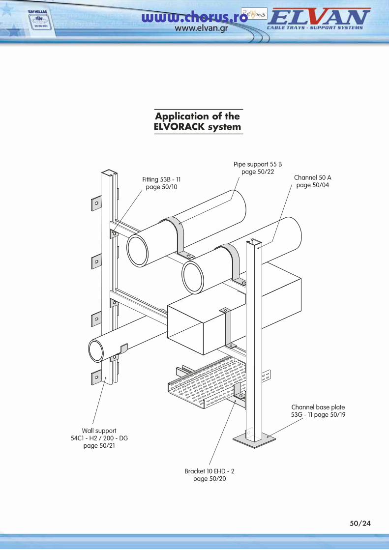
Application of the ELVORACK system
50/24
www.chorus.ro
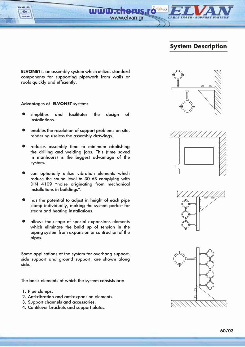
60/03
ELVONET is an assembly system which utilizes standard components for supporting pipework from walls or roofs quickly and efficiently.
Advantages of ELVONET system:
• simplifies and facilitates the design of installations.
• enables the resolution of support problems on site, rendering useless the assembly drawings.
• reduces assembly time to minimum abolishing the drilling and welding jobs. This (time saved in manhours) is the biggest advantage of the system.
• can optionally utilize vibration elements which reduce the sound level to 30 dB complying with DIN 4109 “noise originating from mechanical installations in buildings”.
• has the potential to adjust in height of each pipe clamp individually, making the system perfect for steam and heating installations.
• allows the usage of special expansions elements which eliminate the build up of tension in the piping system from expansion or contraction of the pipes.
Some applications of the system for overhang support, side support and ground support, are shown along side.
The basic elements of which the system consists are:
1. Pipe clamps.2. Anti-ribration and anti-expansion elements.3. Support channels and accessories.4. Cantilever brackets and support plates.
System Description
www.chorus.ro
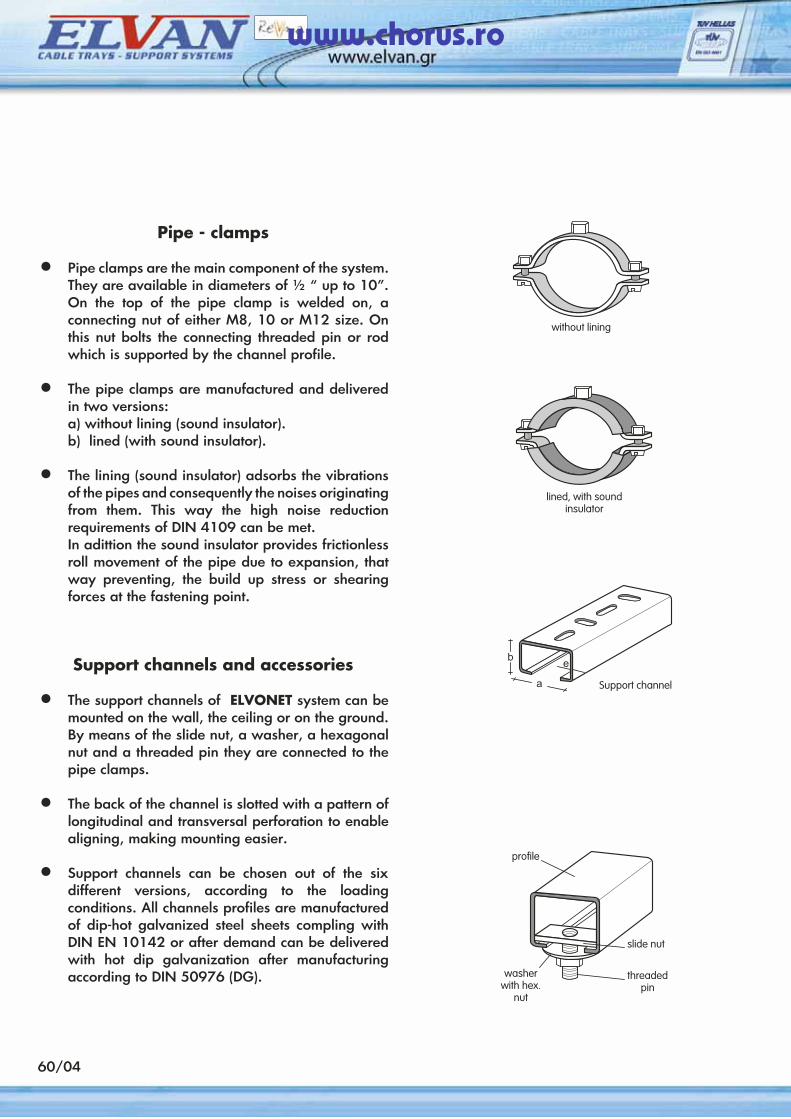
60/04
Pipe - clamps
• Pipe clamps are the main component of the system. They are available in diameters of ½ “ up to 10”. On the top of the pipe clamp is welded on, a connecting nut of either M8, 10 or M12 size. On this nut bolts the connecting threaded pin or rod which is supported by the channel profile.
• The pipe clamps are manufactured and delivered in two versions:
a) without lining (sound insulator). b) lined (with sound insulator).
• The lining (sound insulator) adsorbs the vibrations of the pipes and consequently the noises originating from them. This way the high noise reduction requirements of DIN 4109 can be met.
In adittion the sound insulator provides frictionless roll movement of the pipe due to expansion, that way preventing, the build up stress or shearing forces at the fastening point.
Support channels and accessories
• The support channels of ELVONET system can be mounted on the wall, the ceiling or on the ground. By means of the slide nut, a washer, a hexagonal nut and a threaded pin they are connected to the pipe clamps.
• The back of the channel is slotted with a pattern of longitudinal and transversal perforation to enable aligning, making mounting easier.
• Support channels can be chosen out of the six different versions, according to the loading conditions. All channels profiles are manufactured of dip-hot galvanized steel sheets compling with DIN EN 10142 or after demand can be delivered with hot dip galvanization after manufacturing according to DIN 50976 (DG).
www.chorus.ro
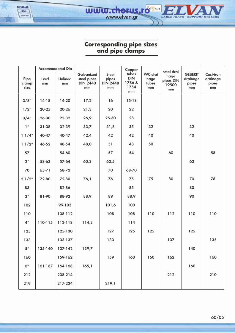
60/05
Corresponding pipe sizesand pipe clamps
Accommodated Dia Coppertubes DIN
1786 & 1754mm
steel drai nage
pipes DIN 19500
mm
Pipe clamp size
Lined mm
Unlinedmm
Galvanizedsteel pipesDIN 2440
mm
Steel pipes
DIN 2448 mm
PVC drainage tubesmm
GEBERIT drainage
pipesmm
Cast-irondrainage
pipesmm
3/8”
1/2”
3/4”
1”
1 1/4”
1 1/2”
57
2”
70
2 1/2”
83
3”
102
110
4”
125
133
5”
160
6”
212
219
14-18
20-25
26-30
31-38
40-47
46-52
58-63
65-71
72-80
81-90
110-115
135-140
161-167
14-20
20-26
25-32
32-39
40-47
48-54
54-60
57-64
68-72
72-80
82-86
88-92
99-103
108-112
112-118
125-130
133-137
137-142
159-162
164-168
208-214
217-224
17,2
21,3
26,9
33,7
42,4
48,0
60,3
76,1
88,9
114,3
139,7
165,1
16
20
25-30
31,8
42
51
57
63,5
70
76
89
101,6
108
127
133
159
219,1
15-18
22
28
35
42
48
54
68-70
75
85
88,9
100
108
114
125
160
32
40
50
75
110
125
160
60
80
112
137
162
212
32
40
63
70
80
90
110
125
140
160
58
78
110
135
160
210
www.chorus.ro
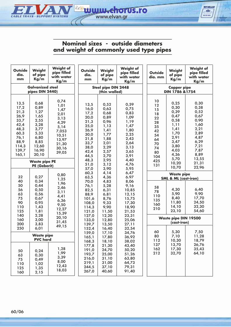
60/06
Nominal sizes - outside diametersand weight of commonly used type pipes
Outsidedia. mm
Weight of pipeKg/m
Weight of pipe filled with water
Kg/m
Galvanized steelpipes DIN 2440)
13,517,221,326,933,742,448,360,376,188,9
114,3139,7165,1
0,680,891,271,652,553,283,775,336,808,8512,6016,9020,10
0,741,011,472,013,134,295,14
7,05310,5113,9721,3030,1639,05
Waste pipe PEPE (Geberit)
32405056637590
110125140160200250
0,270,340,440,500,560,670,951,431,812,283,003,836,01
0,801,251,962,463,114,416,369,5012,2715,3920,1031,4549,15
Waste pipePVC hard
506375110125160
0,240,300,491,021,352,15
1,281,993,398,00
12,4318,03
Outsidedia. mm
Weight of pipeKg/m
Weight of pipe filled with water
Kg/m
Steel pipe DIN 2448(thin walled)
13,516,017,220,021,325,026,930,021,833,738,042,444,548,351,057,060,363,570,076,182,588,9
101,6108,0114,3121,0127,0133,0139,7152,4159,0165,1168,3177,8191,0193,7216,0219,1244,5267,0
0,520,630,680,890,961,131,411,771,882,012,292,572,702,953,123,904,144,364,835,286,316,818,769,339,90
11,5012,2012,8013,5016,4017,1017,8018,1021,3024,7025,0031,1031,0037,1040,60
0,590,750,831,091,191,471,802,252,432,643,133,653,914,404,765,956,476.978,069,16
10,8512,1515,7517,3018,9021,5323,3125,0627,1132,5434,7636,9238,0243,4050,2051,2663,8064,7379,3191,40
Outsidedia. mm
Weight of pipeKg/m
Weight of pipe filled with water
Kg/m
Copper pipeDIN 1786 &1754
10121518222835425464707480
104425131
0,250,300,390,470,581,111,411,702,913,473,804,034,365,7010,2010,70
0,300,380,520,670,901,602,212,894,876,297,217,878,89
13,5521,3122,96
Waste pipeSML & ML (cast-iron)
5878
110135160210
4,305,908,40
11,8014,1023,10
6,409,90
17,7024,5032,3054,60
Waste pipe DIN 19500(cast-iron)
6080
112137162212
5,307,10
10,3013,7017,3032,70
7,5011,2818,7926,7635,4364,10
www.chorus.ro
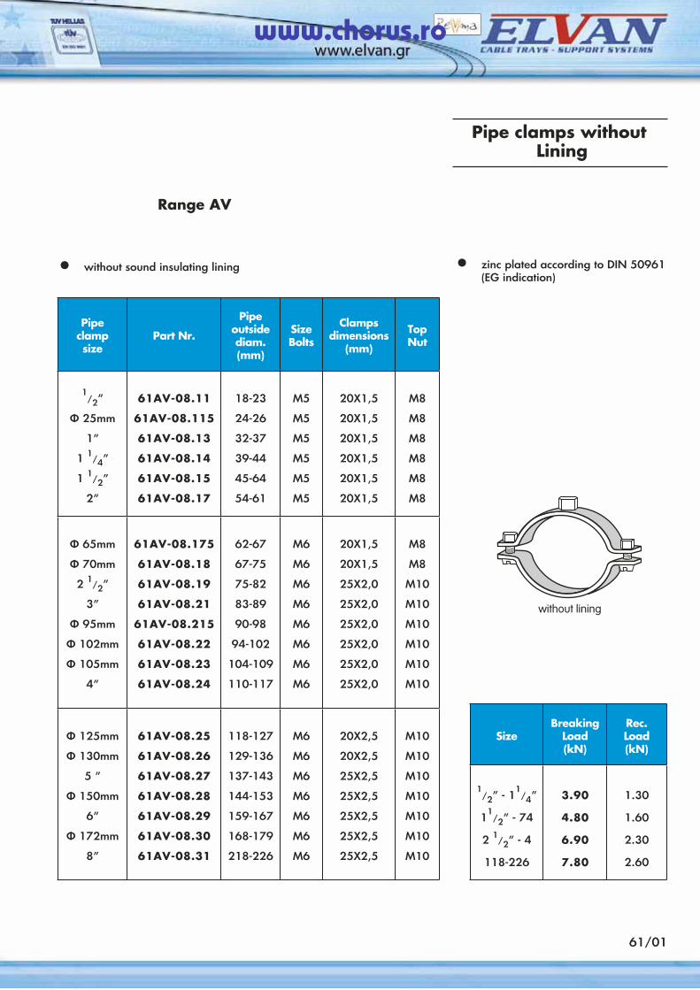
61/01
Pipe clamps without Lining
Range AV
• without sound insulating lining • zinc plated according to DIN 50961 (EG indication)
Pipeclampsize
Part Nr.
Pipe outside diam. (mm)
SizeBolts
Clampsdimensions
(mm)
TopNut
1/2”
Φ 25mm
1”
1 1/4”
1 1/2”
2”
61AV-08.11
61AV-08.115
61AV-08.13
61AV-08.14
61AV-08.15
61AV-08.17
18-23
24-26
32-37
39-44
45-64
54-61
Μ5
Μ5
Μ5
Μ5
Μ5
Μ5
20Χ1,5
20Χ1,5
20Χ1,5
20Χ1,5
20Χ1,5
20Χ1,5
M8
Μ8
Μ8
Μ8
Μ8
Μ8
Φ 65mm
Φ 70mm
2 1/2”
3”
Φ 95mm
Φ 102mm
Φ 105mm
4”
61AV-08.175
61AV-08.18
61AV-08.19
61AV-08.21
61AV-08.215
61AV-08.22
61AV-08.23
61AV-08.24
62-67
67-75
75-82
83-89
90-98
94-102
104-109
110-117
Μ6
Μ6
Μ6
Μ6
Μ6
Μ6
Μ6
Μ6
20Χ1,5
20Χ1,5
25Χ2,0
25Χ2,0
25Χ2,0
25Χ2,0
25Χ2,0
25Χ2,0
M8
Μ8
Μ10
Μ10
Μ10
Μ10
Μ10
Μ10
Φ 125mm
Φ 130mm
5 ”
Φ 150mm
6”
Φ 172mm
8”
61AV-08.25
61AV-08.26
61AV-08.27
61AV-08.28
61AV-08.29
61AV-08.30
61AV-08.31
118-127
129-136
137-143
144-153
159-167
168-179
218-226
Μ6
Μ6
Μ6
Μ6
Μ6
Μ6
Μ6
20Χ2,5
20Χ2,5
25Χ2,5
25Χ2,5
25Χ2,5
25Χ2,5
25Χ2,5
M10
Μ10
Μ10
Μ10
Μ10
Μ10
Μ10
SizeBreaking
Load (kN)
Rec. Load(kN)
1/2” - 1
1/4”
11/2” - 74
2 1/2” - 4
118-226
3.90
4.80
6.90
7.80
1.30
1.60
2.30
2.60
www.chorus.ro
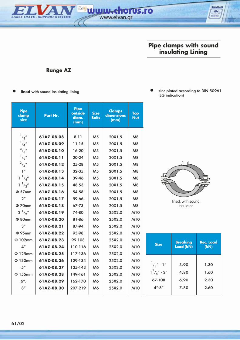
61/02
Pipe clamps with soundinsulating Lining
Range AZ
• lined with sound insulating lining • zinc plated according to DIN 50961 (EG indication)
Pipeclampsize
Part Nr.
Pipe outside diam. (mm)
SizeBolts
Clampsdimensions
(mm)
TopNut
1/8”
1/4”
3/8”
1/2”
3/4”
1”
1 1/4”
1 1/2”
Φ 57mm
2”
Φ 70mm
2 1/2”
Φ 80mm
3”
Φ 95mm
Φ 102mm
4”
Φ 125mm
Φ 130mm
5”
Φ 155mm
6”.
8”
61AZ-08.08
61AZ-08.09
61AZ-08.10
61AZ-08.11
61AZ-08.12
61AZ-08.13
61AZ-08.14
61AZ-08.15
61AZ-08.16
61AZ-08.17
61AZ-08.18
61AZ-08.19
61AZ-08.20
61AZ-08.21
61AZ-08.22
61AZ-08.23
61AZ-08.24
61AZ-08.25
61AZ-08.26
61AZ-08.27
61AZ-08.28
61AZ-08.29
61AZ-08.30
8-11
11-15
16-20
20-24
25-28
32-35
39-46
48-53
54-58
59-66
67-73
74-80
81-86
87-94
95-98
99-108
110-116
117-136
129-134
135-143
149-161
162-170
207-219
Μ5
Μ5
Μ5
Μ5
Μ5
Μ5
Μ5
Μ6
Μ6
Μ6
Μ6
Μ6
Μ6
Μ6
Μ6
Μ6
Μ6
Μ6
M6
M6
M6
M6
M6
20Χ1,5
20Χ1,5
20Χ1,5
20Χ1,5
20Χ1,5
20Χ1,5
20Χ1,5
20Χ1,5
20Χ1,5
20Χ1,5
20Χ1,5
25Χ2,0
25Χ2,0
25Χ2,0
25Χ2,0
25Χ2,0
25Χ2,0
25Χ2,0
25Χ2,0
25Χ2,0
25Χ2,0
25Χ2,0
25Χ2,0
M8
Μ8
Μ8
Μ8
Μ8
Μ8
M8
Μ8
Μ8
Μ8
Μ8
Μ10
M10
Μ10
Μ10
Μ10
Μ10
Μ10
M10
M10
M10
M10
M10
Size BreakingLoad (kN)
Rec. Load(kN)
1/8” - 1”
11/4” - 2”
67-108
4”-8”
3.90
4.80
6.90
7.80
1.30
1.60
2.30
2.60
www.chorus.ro
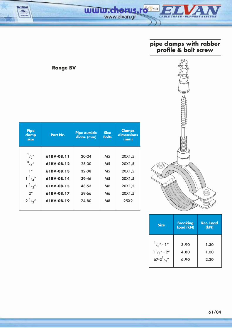
61/04
pipe clamps with rabber profile & bolt screw
Range BV
Pipeclampsize
Part Nr. Pipe outside diam. (mm)
SizeBolts
Clampsdimensions
(mm)
1/2”
3/4”
1”
1 1
/4”
1 1/2”
2”
2 1/2”
61BV-08.11
61BV-08.12
61BV-08.13
61BV-08.14
61BV-08.15
61BV-08.17
61BV-08.19
20-24
25-30
32-38
39-46
48-53
59-66
74-80
Μ5
Μ5
Μ5
Μ5
Μ6
Μ6
Μ8
20Χ1,5
20Χ1,5
20Χ1,5
20Χ1,5
20Χ1,5
20Χ1,5
25Χ2
Size BreakingLoad (kN)
Rec. Load(kN)
1/8” - 1”
11/4” - 2”
67-21/2”
3.90
4.80
6.90
1.30
1.60
2.30
www.chorus.ro
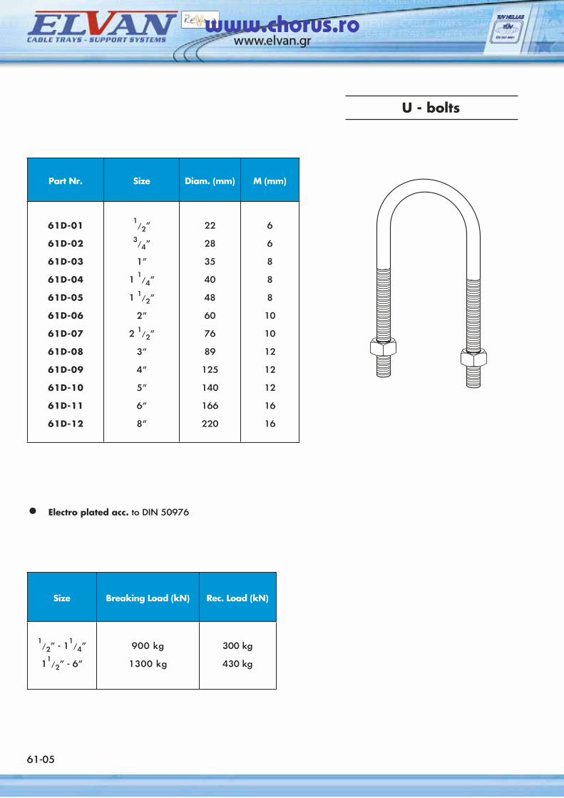
U - bolts
• Electro plated acc. to DIN 50976
61-05
Part Nr. Size Diam. (mm) M (mm)
61D-01
61D-02
61D-03
61D-04
61D-05
61D-06
61D-07
61D-08
61D-09
61D-10
61D-11
61D-12
1/2”
3/4”
1”
1 1/4”
1 1/2”
2”
2 1/2”
3”
4”
5”
6”
8”
22
28
35
40
48
60
76
89
125
140
166
220
6
6
8
8
8
10
10
12
12
12
16
16
Size Breaking Load (kN) Rec. Load (kN)
1/2” - 1
1/4”
11/2” - 6”
900 kg
1300 kg
300 kg
430 kg
www.chorus.ro
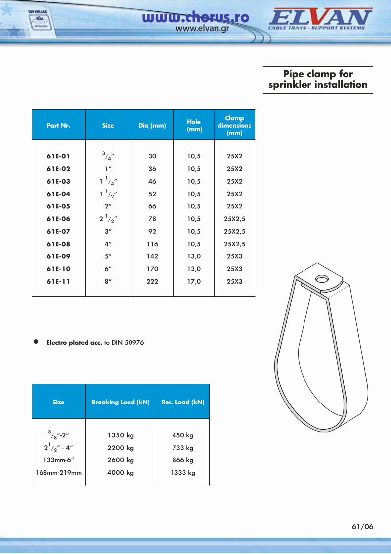
61/06
Pipe clamp forsprinkler installation
Part Nr. Size Dia (mm) Hole (mm)
Clamp dimensions
(mm)
61E-01
61E-02
61E-03
61E-04
61E-05
61E-06
61E-07
61E-08
61E-09
61E-10
61E-11
3/4”
1”
1 1/4”
1 1/2”
2”
2 1/2”
3”
4”
5”
6”
8”
30
36
46
52
66
78
92
116
142
170
222
10,5
10,5
10,5
10,5
10,5
10,5
10,5
10,5
13,0
13,0
17,0
25X2
25X2
25X2
25X2
25X2
25X2,5
25X2,5
25X2,5
25X3
25X3
25X3
• Electro plated acc. to DIN 50976
Size Breaking Load (kN) Rec. Load (kN)
3/8”-2”
21
/2” - 4”
133mm-6”
168mm-219mm
1350 kg
2200 kg
2600 kg
4000 kg
450 kg
733 kg
866 kg
1333 kg
www.chorus.ro
62/01
Noise Reduction
There is a constantly growing demand for quieter buildings, set formaly by international standards.
The latest DIN edition 4109 limits the maximum sound level to 30 dB for noises originating from mechanical installations. It is the responsibility of the consulant and mechanical engineer to comply with these standards.
ΕLVAN responding to this demand created a type of rubber sound insulator which achives a high degree of noise reduction, from pipes, ducts and their supports to the building. Transmision of structure born noises is influenced by a variety of factors such as:
a) the depth of the anchor masonry
b) the distance between supports,
c) the distance of the noise agent from the ceiling of the walls and many others.
The most important application of the rubber sound insulator is on the pipe clamps since through them the transmission of water hammer, water flow and pipe expansions noises is occuring.
The Elvonet sound insulator isolates the pipe clamp from the pipe reducing the noise level varying in each case from 24 dB up to 18 dB.The ELVAN sound insulator products cover up to 90% of all cases dealt in current practise and there are coming in there types as can be seen on the next page.
Pipe fixture insulators
• Noise reduction up to 24 dB.
• High sliding elasticity.
• Protection of pipes by covering of pipe-clamps edges.
• High temperature resistance.
• Rolling action with pipe expansion
www.chorus.ro
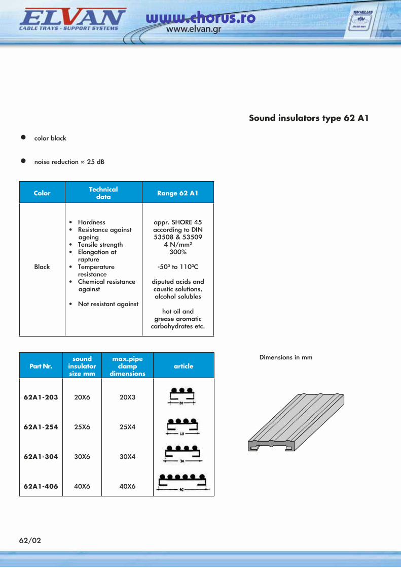
62/02
• color black
• noise reduction ≈ 25 dB
Sound insulators type 62 A1
Color Technicaldata Range 62 Α1
Black
• Hardness• Resistance against ageing• Tensile strength• Elongation at
rapture• Temperature
resistance• Chemical resistance against
• Not resistant against
appr. SHORE 45according to DIN 53508 & 53509
4 N/mm2
300%
-500 to 1100C
diputed acids and caustic solutions, alcohol solubles
hot oil and grease aromatic
carbohydrates etc.
Part Nr.sound
insulator size mm
max.pipe clamp
dimensionsarticle
62A1-203
62Α1-254
62Α1-304
62Α1-406
20X6
25Χ6
30Χ6
40Χ6
20X3
25Χ4
30Χ4
40Χ6
Dimensions in mm
www.chorus.ro
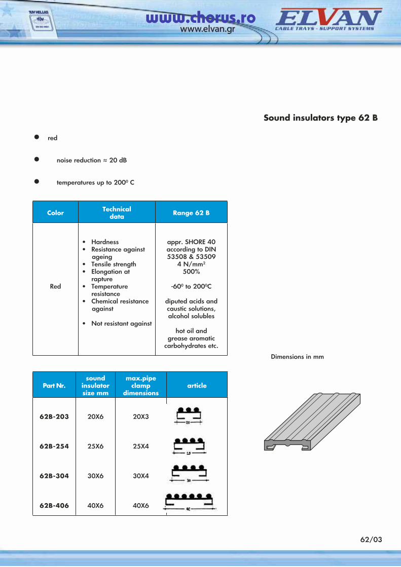
62/03
• red
• noise reduction ≈ 20 dB
• temperatures up to 2000 C
Sound insulators type 62 B
Color Technicaldata Range 62 B
Red
• Hardness• Resistance against ageing• Tensile strength• Elongation at
rapture• Temperature
resistance• Chemical resistance against
• Not resistant against
appr. SHORE 40according to DIN 53508 & 53509
4 N/mm2
500%
-600 to 2000C
diputed acids and caustic solutions, alcohol solubles
hot oil and grease aromatic
carbohydrates etc.
Part Nr.sound
insulator size mm
max.pipe clamp
dimensionsarticle
62B-203
62B-254
62B-304
62B-406
20X6
25Χ6
30Χ6
40Χ6
20X3
25Χ4
30Χ4
40Χ6
Dimensions in mm
www.chorus.ro

63/01
PG: to be used indoors in almost dry atmosphere
Support channel 63 AP
• made of galvanized sheet steel acc. to DIN EN 110142 Part Nr. indication: (PG).
• available also in hot dip galvanized metal sheet after manufacturing according to DIN 50976 Part Nr. indication: (DG).
• standard length 2,5 m.
• Pipes through pipe clamps can be safely and simply fitted to all hydraulic installations, central heating systems and air conditioning systems.
• High tensile strength in bending due to the carefully designed crossection of the profile.
• Associating accessories part No.
nut : 63G8washer : 63G28 or 63G38
Profile 63 AP32 Χ 20 Χ 1,2 mm
Part Nr. WeightKG/p
63AP.PGDistance between supports, m
L (m) = 0,5 1,0 1,5 2,0
Maximum loads Ρ in ΚΡ
119,0
89,1
59,4
49,5
59,4
44,5
29,7
27,4
39,6
29,7
19,8
16,5
29,7
22,3
14,8
12,3
www.chorus.ro

63/02
PG: to be used indoors in almost dry atmosphere
Support channel63AQ - 63AR
• The loads given below do not exceed the allowable stress as well as maximum deflection (L/150), on the steel.
Distance between supports, mL (m) = 0,5 1,0 1,5 2,0
Maximum loads Ρ in ΚΡ
226,6
170,0
113,3
94,4
113,3
85,6
56,6
47,2
75,5
56,6
37,7
31,4
56,6
42,5
28,3
23,6
Profile AQ40 Χ 20 Χ 1,5 mm
Part Nr. WeightKG/p
63AQ.PG
Distance between supports, m
L (m) = 0,5 1,0 1,5 2,0
Maximum loads Ρ in ΚΡ
293,5
220,1
146,7
122,3
146,7
110,0
73,3
61,1
97,8
73,3
48,9
40,7
73,3
55,0
36,6
30,5
Profile AR40 Χ 40 Χ 2.0 mm
Part Nr. WeightKG/p
63AQ.PG
www.chorus.ro
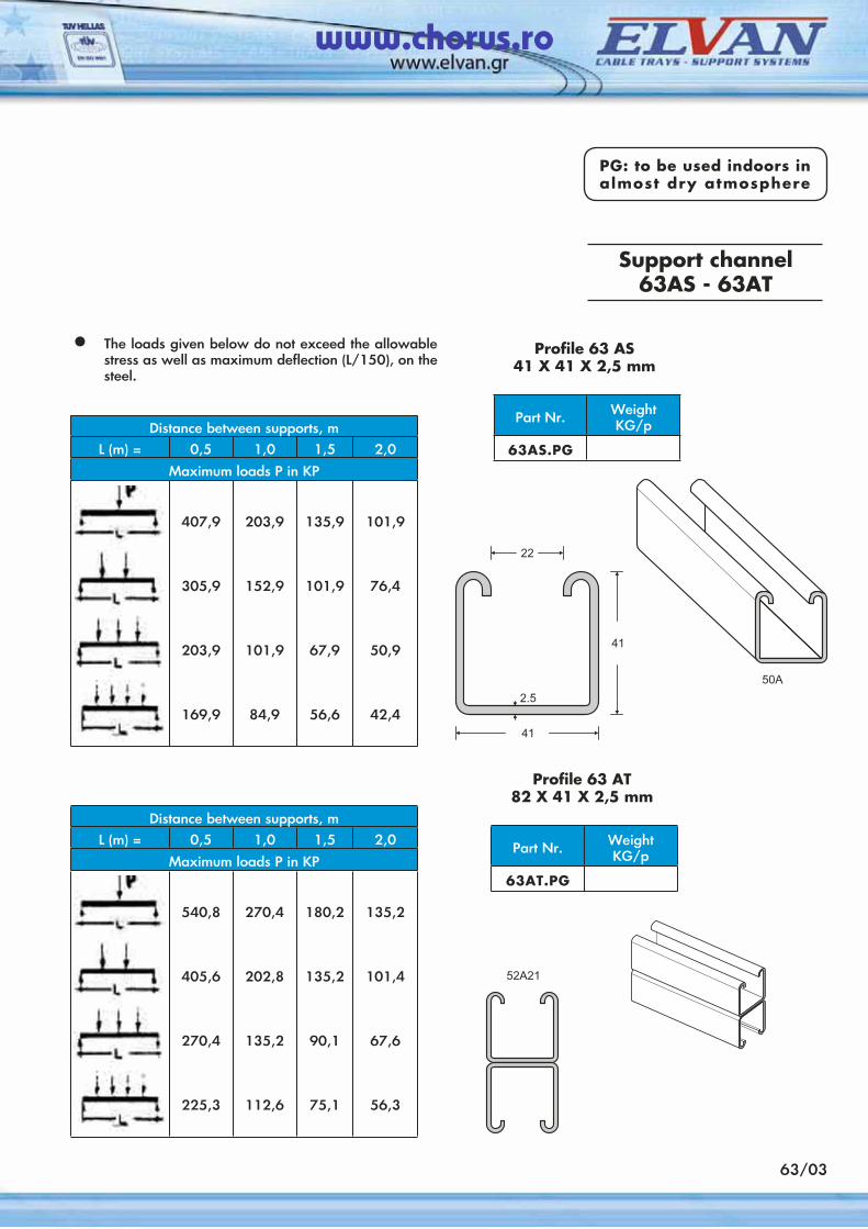
63/03
PG: to be used indoors in almost dry atmosphere
Support channel63AS - 63AT
• The loads given below do not exceed the allowable stress as well as maximum deflection (L/150), on the steel.
Distance between supports, mL (m) = 0,5 1,0 1,5 2,0
Maximum loads Ρ in ΚΡ
407,9
305,9
203,9
169,9
203,9
152,9
101,9
84,9
135,9
101,9
67,9
56,6
101,9
76,4
50,9
42,4
Profile 63 AS41 Χ 41 Χ 2,5 mm
Part Nr. WeightKG/p
63AS.PG
Distance between supports, mL (m) = 0,5 1,0 1,5 2,0
Maximum loads Ρ in ΚΡ
540,8
405,6
270,4
225,3
270,4
202,8
135,2
112,6
180,2
135,2
90,1
75,1
135,2
101,4
67,6
56,3
Profile 63 AT82 Χ 41 Χ 2,5 mm
Part Nr. WeightKG/p
63AT.PG
www.chorus.ro
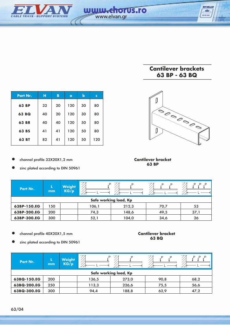
63/04
Cantilever brackets63 BP - 63 BQ
• channel profile 32Χ20Χ1,2 mm
• zinc plated according to DIN 50961
Cantilever bracket63 BP
Part Nr. H B a b c
63 ΒP
63 BQ
63 BR
63 BS
63 BT
32
40
40
41
82
20
20
40
41
41
120
120
120
120
120
30
30
50
50
50
80
80
80
80
120
Part Nr. Lmm
WeightKG/p
Safe working load, Κp
63BP-150.EG 150 106,1 212,3 70,7 53
63BP-200.EG 200 74,3 148,6 49,5 37,1
63BP-300.EG 300 52,1 104,0 34,6 26
• channel profile 40Χ20Χ1,5 mm
• zinc plated according to DIN 50961
Cantilever bracket63 BQ
Part Nr. Lmm
WeightKG/p
Safe working load, Κp
63BQ-150.EG 200 136,5 273,0 90,8 68,2
63BQ-200.EG 250 113,3 226,6 75,5 56,6
63BQ-300.EG 300 94,4 188,8 62,9 47,2
www.chorus.ro
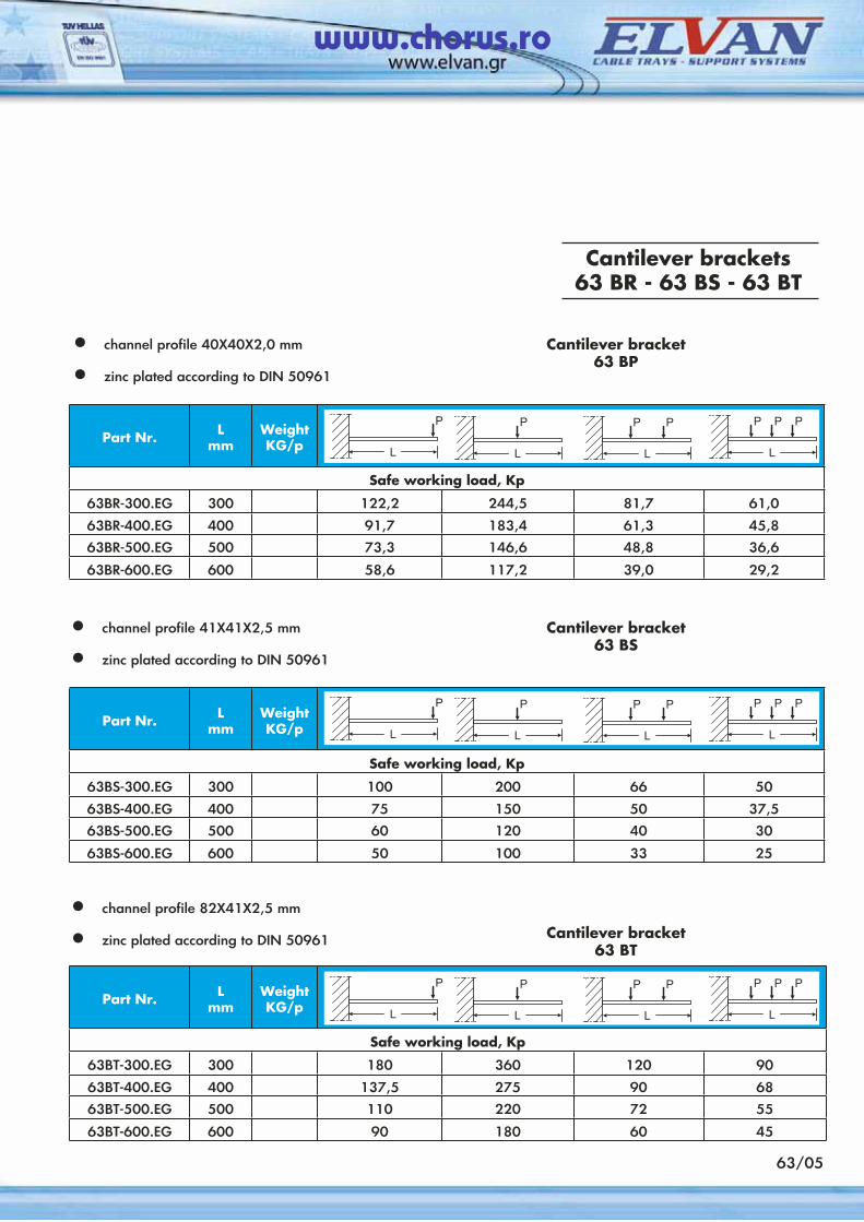
63/05
Cantilever brackets63 BR - 63 BS - 63 ΒT
• channel profile 40Χ40Χ2,0 mm
• zinc plated according to DIN 50961
Cantilever bracket63 BΡ
Part Nr. Lmm
WeightKG/p
Safe working load, Κp
63BR-300.EG 300 122,2 244,5 81,7 61,0
63BR-400.EG 400 91,7 183,4 61,3 45,8
63BR-500.EG 500 73,3 146,6 48,8 36,6
63BR-600.EG 600 58,6 117,2 39,0 29,2
• channel profile 41Χ41Χ2,5 mm
• zinc plated according to DIN 50961
Cantilever bracket63 BS
Part Nr. Lmm
WeightKG/p
Safe working load, Κp
63BS-300.EG 300 100 200 66 50
63BS-400.EG 400 75 150 50 37,5
63BS-500.EG 500 60 120 40 30
63BS-600.EG 600 50 100 33 25
• channel profile 82Χ41Χ2,5 mm
• zinc plated according to DIN 50961 Cantilever bracket63 BT
Part Nr. Lmm
WeightKG/p
Safe working load, Κp
63BT-300.EG 300 180 360 120 90
63BT-400.EG 400 137,5 275 90 68
63BT-500.EG 500 110 220 72 55
63BT-600.EG 600 90 180 60 45
www.chorus.ro
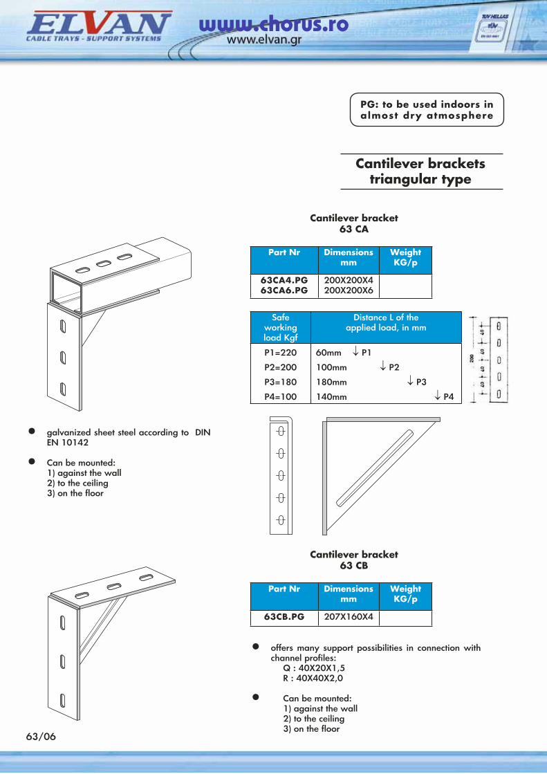
63/06
PG: to be used indoors in almost dry atmosphere
Cantilever bracketstriangular type
Cantilever bracket63 CA
• galvanized sheet steel according to DIN EN 10142
• Can be mounted: 1) against the wall 2) to the ceiling 3) on the floor
Part Nr Dimensionsmm
WeightKG/p
63CA4.PG63CA6.PG
200X200X4200X200X6
Safe workingload Kgf
Distance L of theapplied load, in mm
P1=220
P2=200
P3=180
P4=100
60mm ↓ Ρ1
100mm ↓ Ρ2
180mm ↓ Ρ3
140mm ↓ Ρ4
Cantilever bracket63 CΒ
Part Nr Dimensionsmm
WeightKG/p
63CΒ.PG 207X160X4
• offers many support possibilities in connection with channel profiles:
Q : 40X20X1,5 R : 40X40X2,0
• Can be mounted: 1) against the wall 2) to the ceiling 3) on the floor
www.chorus.ro
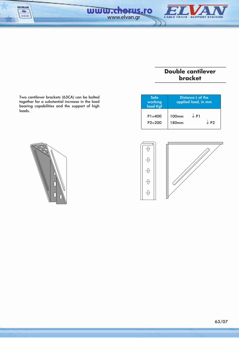
63/07
Two cantilever brackets (63CA) can be bolted together for a substantial increase in the load bearing capabilities and the support of high loads.
Safe workingload Kgf
Distance L of theapplied load, in mm
P1=400
P2=200
100mm ↓ Ρ1
180mm ↓ Ρ2
Double cantilever bracket
www.chorus.ro
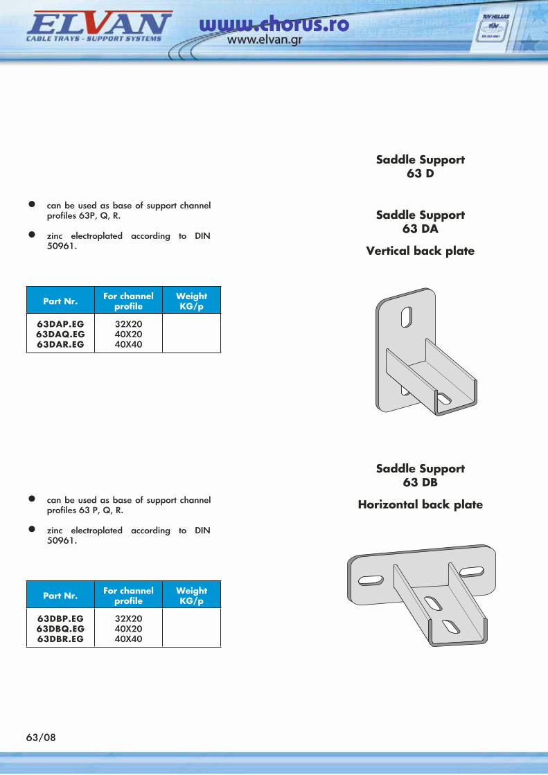
63/08
Saddle Support63 D
Saddle Support63 DA
Vertical back plate
• can be used as base of support channel profiles 63P, Q, R.
• zinc electroplated according to DIN 50961.
Part Nr. For channelprofile
WeightKG/p
63DAP.EG63DAQ.EG63DAR.EG
32X2040X2040X40
Saddle Support63 DΒ
Horizontal back plate• can be used as base of support channel profiles 63 P, Q, R.
• zinc electroplated according to DIN 50961.
Part Nr. For channelprofile
WeightKG/p
63DBP.EG63DBQ.EG63DBR.EG
32X2040X2040X40
www.chorus.ro
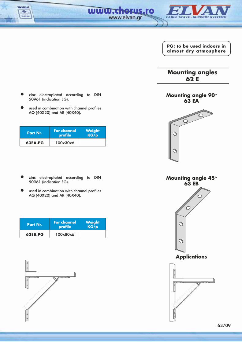
63/09
Mounting angles 62 E
PG: to be used indoors in almost dry atmosphere
Mounting angle 90o
63 EA• zinc electroplated according to DIN
50961 (indication EG).
• used in combination with channel profiles AQ (40X20) and AR (40X40).
Part Nr. For channelprofile
WeightKG/p
63EA.PG 100x30x6
Mounting angle 45o
63 EΒ• zinc electroplated according to DIN
50961 (indication EG).
• used in combination with channel profiles AQ (40X20) and AR (40X40).
Part Nr. For channelprofile
WeightKG/p
63EΒ.PG 100x80x6
Αpplications
www.chorus.ro
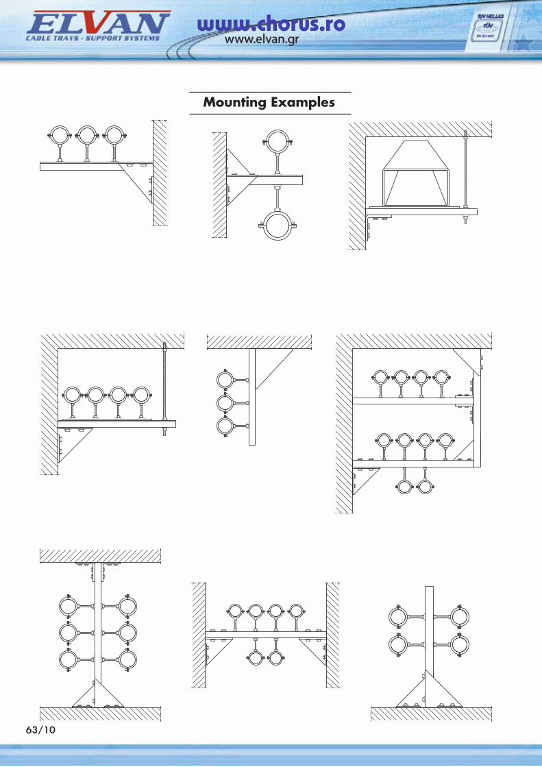
Mounting Examples
63/10
www.chorus.ro
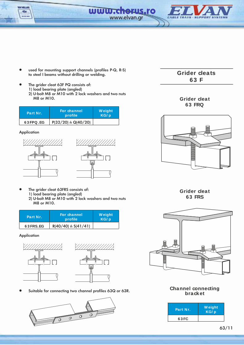
63/11
Grider cleat63 FRQ
• used for mounting support channels (profiles P-Q, R-S) to steel I beams without drilling or welding.
• The grider cleat 63F PQ consists of: 1) load bearing plate (angled) 2) U-bolt M8 or M10 with 2 lock washers and two nuts
M8 or M10.
Part Nr. For channelprofile
WeightKG/p
63FPQ.EG P(32/20) ή Q(40/20)
Application
• The grider cleat 63FRS consists of: 1) load bearing plate (angled) 2) U-bolt M8 or M10 with 2 lock washers and two nuts
M8 or M10.
Part Nr. For channelprofile
WeightKG/p
63FRS.EG R(40/40) ή S(41/41)
Application
Grider cleat63 FRS
• Suitable for connecting two channel profiles 63Q or 63R. Channel connectingbracket
Part Nr. WeightKG/p
63FC
Grider cleats 63 F
www.chorus.ro
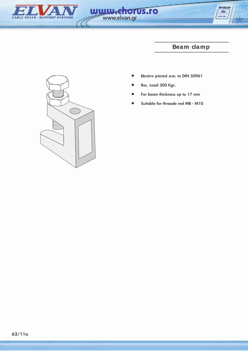
63/11a
• Electro plated acc. to DIN 50961
• Rec. Load 300 Kgr.
• For beam thickness up to 17 mm
• Suitable for threade red MB - M10
Beam clamp
www.chorus.ro
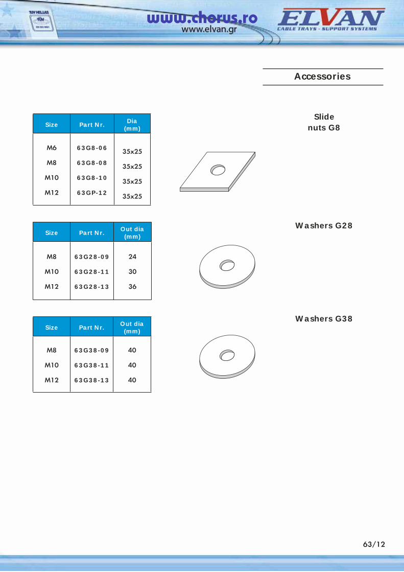
63/12
Slidenuts G8
Washers G28
Washers G38
Size Part Nr. Dia(mm)
M6
Μ8
Μ10
M12
63G8-06
63G8-08
63G8-10
63GP-12
35x25
35x25
35x25
35x25
Size Part Nr. Out dia(mm)
Μ8
Μ10
Μ12
63G28-09
63G28-11
63G28-13
24
30
36
Size Part Nr. Out dia(mm)
Μ8
Μ10
Μ12
63G38-09
63G38-11
63G38-13
40
40
40
Accessories
www.chorus.ro
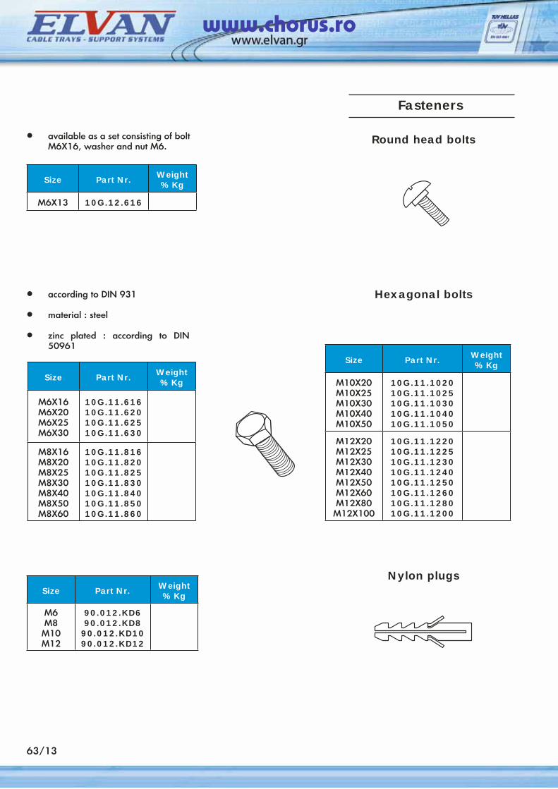
63/13
Round head bolts
Hexagonal bolts
Nylon plugsSize Part Nr. Weight
% Kg
Μ6M8
M10M12
90.012.KD690.012.KD8
90.012.KD1090.012.KD12
• available as a set consisting of bolt Μ6Χ16, washer and nut Μ6.
Size Part Nr. Weight% Kg
Μ6Χ16M6X20M6X25M6X30
10G.11.61610G.11.62010G.11.62510G.11.630
M8X16M8X20M8X25M8X30M8X40M8X50M8X60
10G.11.81610G.11.82010G.11.82510G.11.83010G.11.84010G.11.85010G.11.860
• according to DIN 931
• material : steel
• zinc plated : according to DIN 50961
Size Part Nr. Weight% Kg
Μ6X13 10G.12.616
Size Part Nr. Weight% Kg
Μ10Χ20M10X25M10X30M10X40Μ10Χ50
10G.11.102010G.11.102510G.11.103010G.11.104010G.11.1050
M12X20M12X25M12X30M12X40M12X50M12X60M12X80
Μ12Χ100
10G.11.122010G.11.122510G.11.123010G.11.124010G.11.125010G.11.126010G.11.128010G.11.1200
Fasteners
www.chorus.ro
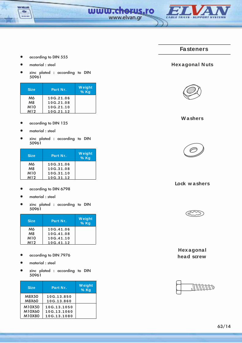
63/14
Size Part Nr. Weight% Kg
Μ6M8
M10M12
10G.21.0610G.21.0810G.21.1010G.21.12
• according to DIN 555
• material : steel
• zinc plated : according to DIN 50961
Size Part Nr. Weight% Kg
Μ6M8
M10M12
10G.31.0610G.31.0810G.31.1010G.31.12
• according to DIN 125
• material : steel
• zinc plated : according to DIN 50961
Size Part Nr. Weight% Kg
Μ6M8
M10M12
10G.41.0610G.41.0810G.41.1010G.41.12
• according to DIN 6798
• material : steel
• zinc plated : according to DIN 50961
Size Part Nr. Weight% Kg
Μ8Χ50M8Χ60
10G.13.85010G.13.860
Μ10Χ50M10Χ60Μ10Χ80
10G.13.105010G.13.106010G.13.1080
• according to DIN 7976
• material : steel
• zinc plated : according to DIN 50961
Hexagonal Nuts
Washers
Lock washers
Hexagonalhead screw
Fasteners
www.chorus.ro
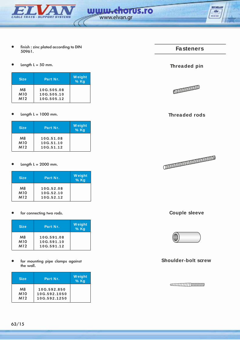
Threaded pin
Threaded rods
Couple sleeve
Shoulder-bolt screw
Size Part Nr. Weight% Kg
M8M10M12
10G.505.0810G.505.1010G.505.12
• finish : zinc plated according to DIN 50961.
• Length L = 50 mm.
Size Part Nr. Weight% Kg
M8M10M12
10G.51.0810G.51.1010G.51.12
• Length L = 1000 mm.
Size Part Nr. Weight% Kg
M8M10M12
10G.52.0810G.52.1010G.52.12
• Length L = 2000 mm.
Size Part Nr. Weight% Kg
M8M10M12
10G.591.0810G.591.1010G.591.12
• for connecting two rods.
Size Part Nr. Weight% Kg
M8M10M12
10G.592.85010G.592.105010G.592.1250
• for mounting pipe clamps against the wall.
Fasteners
63/15
www.chorus.ro
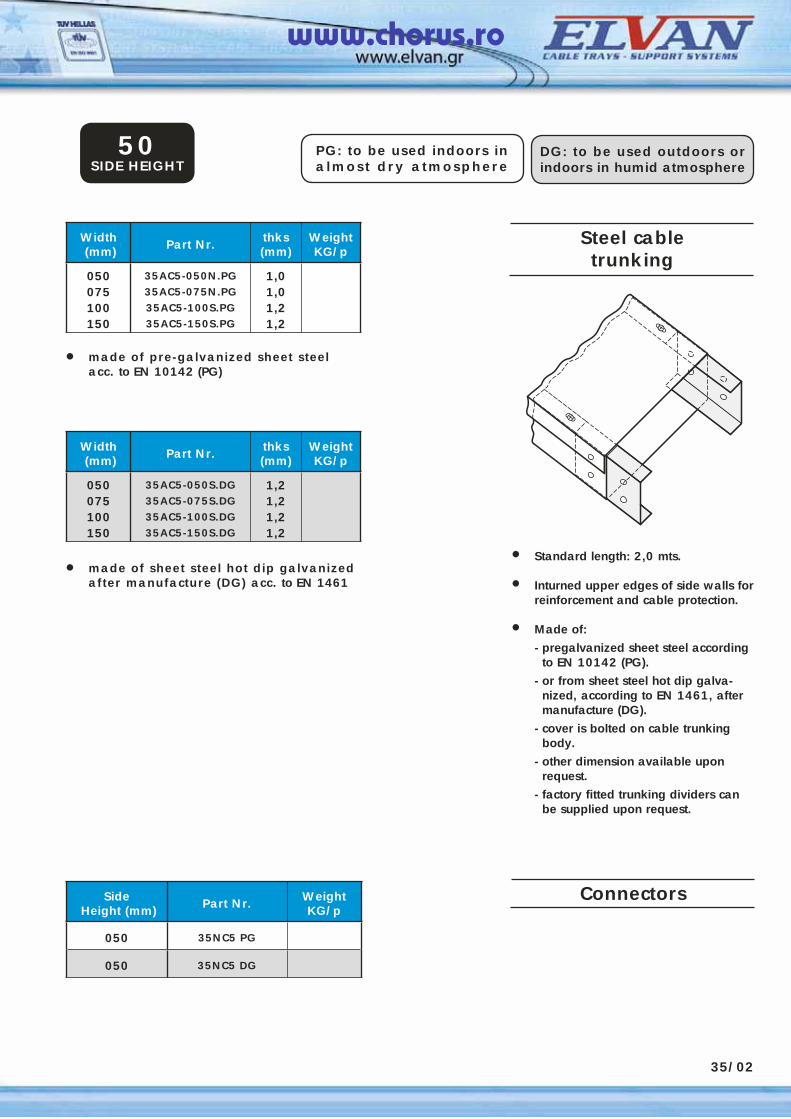
20/01
Steel cabletrunking
Width (mm) Part Nr. thks
(mm)WeightKG/p
050075100150
35AC5-050N.PG35AC5-075N.PG35AC5-100S.PG35AC5-150S.PG
1,01,01,21,2
• Standard length: 2,0 mts.
• Inturned upper edges of side walls for reinforcement and cable protection.
• Made of:
- pregalvanized sheet steel according to EN 10142 (PG).
- or from sheet steel hot dip galva-nized, according to EN 1461, after manufacture (DG).
- cover is bolted on cable trunking body.
- other dimension available upon request.
- factory fitted trunking dividers can be supplied upon request.
• made of pre-galvanized sheet steel acc. to EN 10142 (PG)
PG: to be used indoors in almost dry atmosphere
DG: to be used outdoors or indoors in humid atmosphere
50SIDE HEIGHT
Width (mm) Part Nr. thks
(mm)WeightKG/p
050075100150
35AC5-050S.DG35AC5-075S.DG35AC5-100S.DG35AC5-150S.DG
1,21,21,21,2
• made of sheet steel hot dip galvanized after manufacture (DG) acc. to EN 1461
Side Height (mm) Part Nr. Weight
KG/p
050 35NC5 PG
050 35NC5 DG
Connectors
35/02
www.chorus.ro
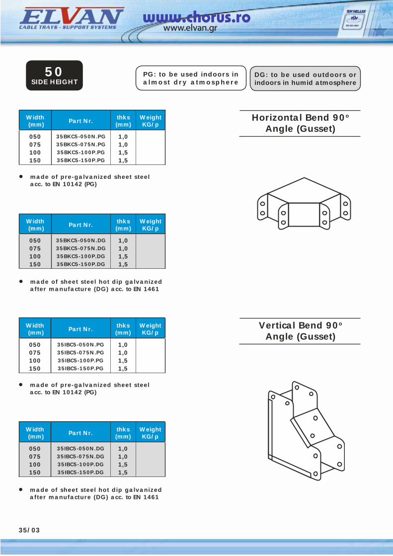
Horizontal Bend 90o
Angle (Gusset)Width (mm) Part Nr. thks
(mm)WeightKG/p
050075100150
35BKC5-050N.PG35BKC5-075N.PG35BKC5-100P.PG35BKC5-150P.PG
1,01,01,51,5
• made of pre-galvanized sheet steel acc. to EN 10142 (PG)
PG: to be used indoors in almost dry atmosphere
DG: to be used outdoors or indoors in humid atmosphere
50SIDE HEIGHT
Width (mm) Part Nr. thks
(mm)WeightKG/p
050075100150
35BKC5-050N.DG35BKC5-075N.DG35BKC5-100P.DG35BKC5-150P.DG
1,01,01,51,5
• made of sheet steel hot dip galvanized after manufacture (DG) acc. to EN 1461
35/03
Width (mm) Part Nr. thks
(mm)WeightKG/p
050075100150
35IBC5-050N.PG35IBC5-075N.PG35IBC5-100P.PG35IBC5-150P.PG
1,01,01,51,5
• made of pre-galvanized sheet steel acc. to EN 10142 (PG)
Width (mm) Part Nr. thks
(mm)WeightKG/p
050075100150
35IBC5-050N.DG35IBC5-075N.DG35IBC5-100P.DG35IBC5-150P.DG
1,01,01,51,5
• made of sheet steel hot dip galvanized after manufacture (DG) acc. to EN 1461
Vertical Bend 90o
Angle (Gusset)
www.chorus.ro
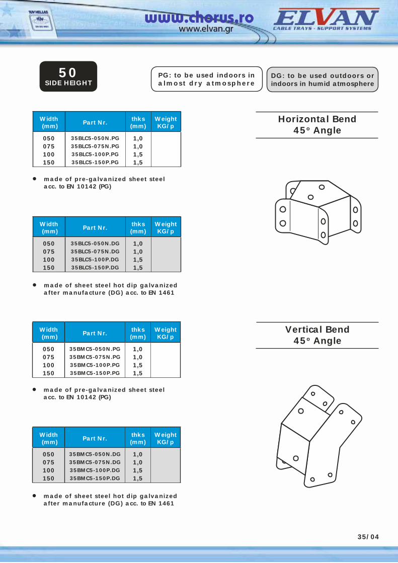
35/04
Horizontal Bend45o Angle
Width (mm) Part Nr. thks
(mm)WeightKG/p
050075100150
35BLC5-050N.PG35BLC5-075N.PG35BLC5-100P.PG35BLC5-150P.PG
1,01,01,51,5
• made of pre-galvanized sheet steel acc. to EN 10142 (PG)
PG: to be used indoors in almost dry atmosphere
DG: to be used outdoors or indoors in humid atmosphere
50SIDE HEIGHT
Width (mm) Part Nr. thks
(mm)WeightKG/p
050075100150
35BLC5-050N.DG35BLC5-075N.DG35BLC5-100P.DG35BLC5-150P.DG
1,01,01,51,5
• made of sheet steel hot dip galvanized after manufacture (DG) acc. to EN 1461
Width (mm) Part Nr. thks
(mm)WeightKG/p
050075100150
35BMC5-050N.PG35BMC5-075N.PG35BMC5-100P.PG35BMC5-150P.PG
1,01,01,51,5
• made of pre-galvanized sheet steel acc. to EN 10142 (PG)
Width (mm) Part Nr. thks
(mm)WeightKG/p
050075100150
35BMC5-050N.DG35BMC5-075N.DG35BMC5-100P.DG35BMC5-150P.DG
1,01,01,51,5
• made of sheet steel hot dip galvanized after manufacture (DG) acc. to EN 1461
Vertical Bend45o Angle
www.chorus.ro
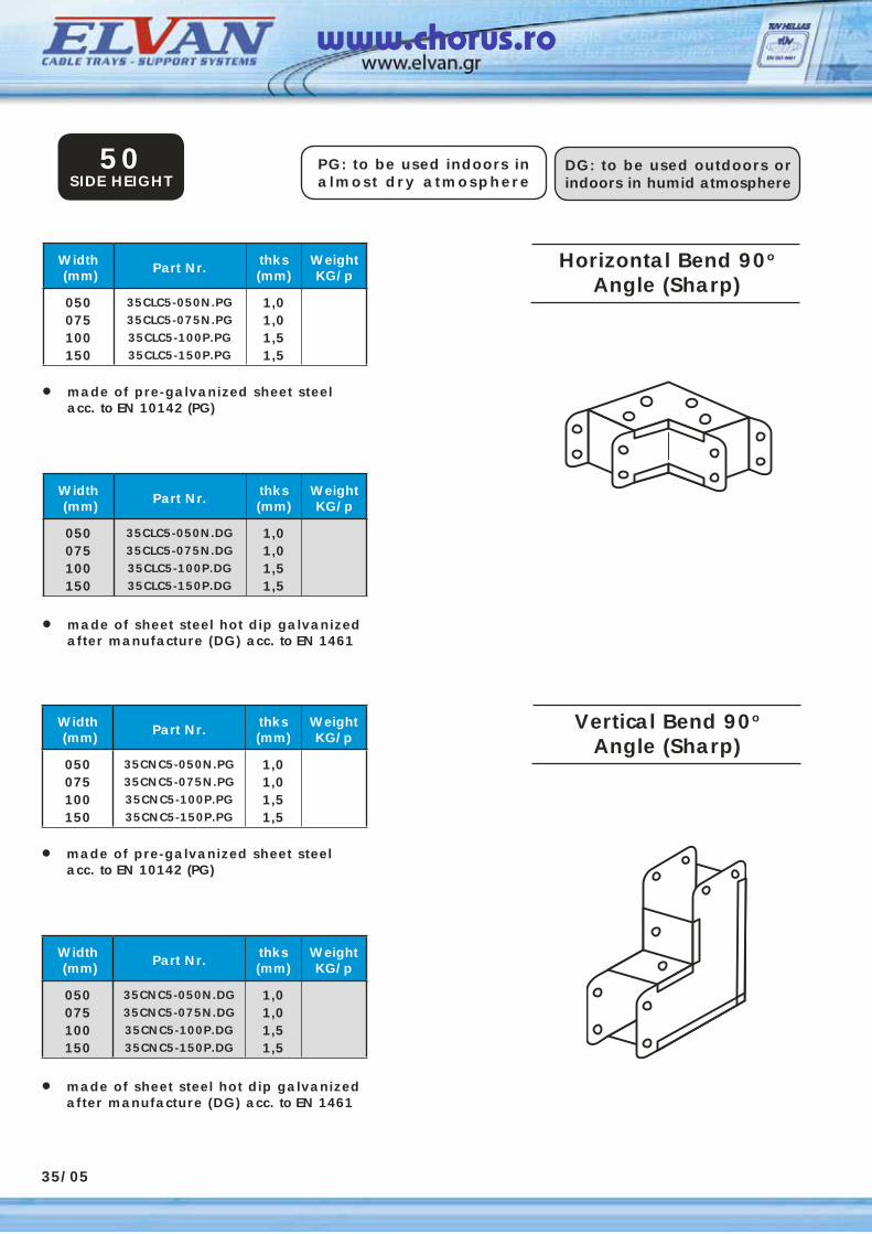
35/05
Horizontal Bend 90o
Angle (Sharp)Width (mm) Part Nr. thks
(mm)WeightKG/p
050075100150
35CLC5-050N.PG35CLC5-075N.PG35CLC5-100P.PG35CLC5-150P.PG
1,01,01,51,5
• made of pre-galvanized sheet steel acc. to EN 10142 (PG)
PG: to be used indoors in almost dry atmosphere
DG: to be used outdoors or indoors in humid atmosphere
50SIDE HEIGHT
Width (mm) Part Nr. thks
(mm)WeightKG/p
050075100150
35CLC5-050N.DG35CLC5-075N.DG35CLC5-100P.DG35CLC5-150P.DG
1,01,01,51,5
• made of sheet steel hot dip galvanized after manufacture (DG) acc. to EN 1461
Width (mm) Part Nr. thks
(mm)WeightKG/p
050075100150
35CNC5-050N.PG35CNC5-075N.PG35CNC5-100P.PG35CNC5-150P.PG
1,01,01,51,5
• made of pre-galvanized sheet steel acc. to EN 10142 (PG)
Width (mm) Part Nr. thks
(mm)WeightKG/p
050075100150
35CNC5-050N.DG35CNC5-075N.DG35CNC5-100P.DG35CNC5-150P.DG
1,01,01,51,5
• made of sheet steel hot dip galvanized after manufacture (DG) acc. to EN 1461
Vertical Bend 90o
Angle (Sharp)
www.chorus.ro

35/06
Horizontal TeeWidth (mm) Part Nr. thks
(mm)WeightKG/p
050075100150
35HEC5-050N.PG35HEC5-075N.PG35HEC5-100P.PG35HEC5-150P.PG
1,01,01,51,5
• made of pre-galvanized sheet steel acc. to EN 10142 (PG)
PG: to be used indoors in almost dry atmosphere
DG: to be used outdoors or indoors in humid atmosphere
50SIDE HEIGHT
Width (mm) Part Nr. thks
(mm)WeightKG/p
050075100150
35HEC5-050N.DG35HEC5-075N.DG35HEC5-100P.DG35HEC5-150P.DG
1,01,01,51,5
• made of sheet steel hot dip galvanized after manufacture (DG) acc. to EN 1461
Width (mm) Part Nr. thks
(mm)WeightKG/p
050075100150
35VEC5-050N.PG35VEC5-075N.PG35VEC5-100P.PG35VEC5-150P.PG
1,01,01,51,5
• made of pre-galvanized sheet steel acc. to EN 10142 (PG)
Width (mm) Part Nr. thks
(mm)WeightKG/p
050075100150
35VEC5-050N.DG35VEC5-075N.DG35VEC5-100P.DG35VEC5-150P.DG
1,01,01,51,5
• made of sheet steel hot dip galvanized after manufacture (DG) acc. to EN 1461
Vertical Tee
www.chorus.ro
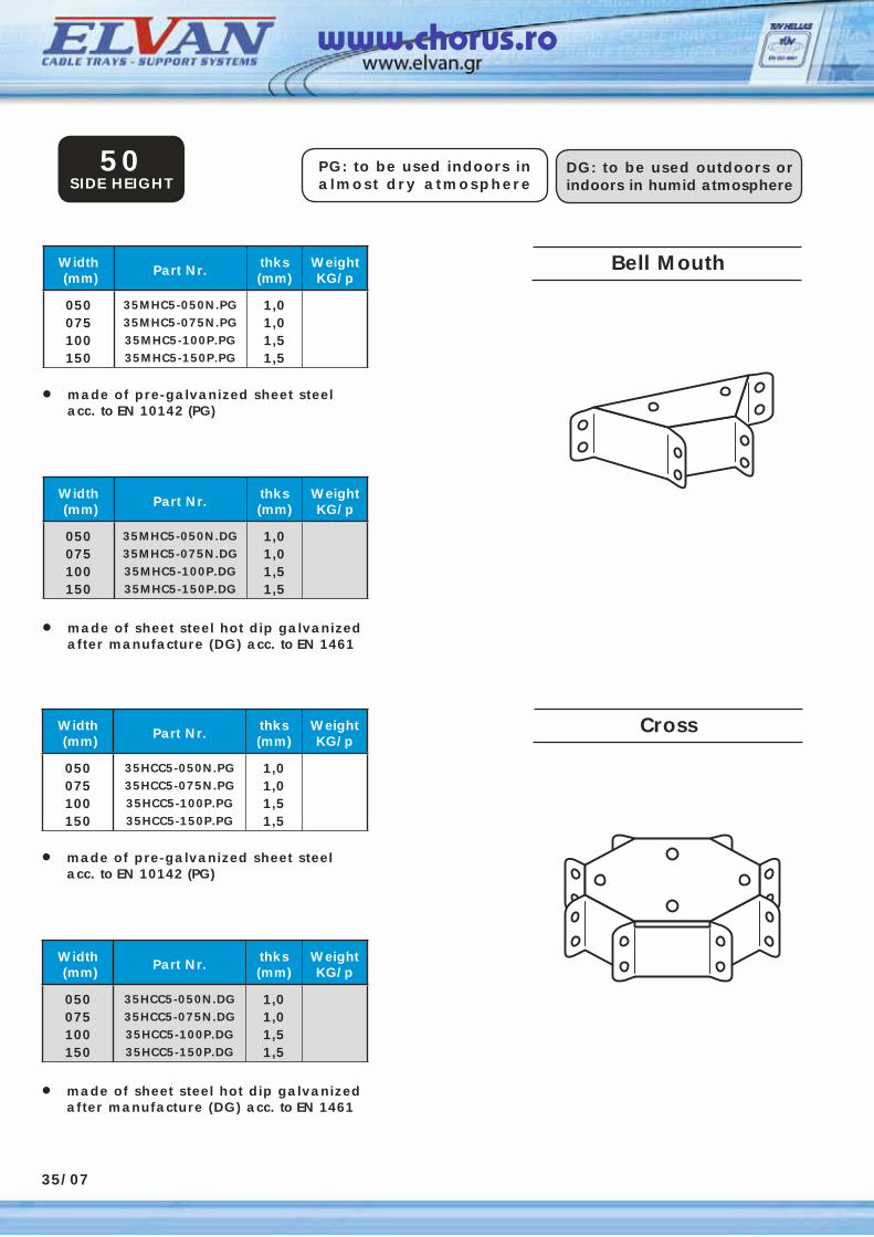
35/07
Bell MouthWidth (mm) Part Nr. thks
(mm)WeightKG/p
050075100150
35MHC5-050N.PG35MHC5-075N.PG35MHC5-100P.PG35MHC5-150P.PG
1,01,01,51,5
• made of pre-galvanized sheet steel acc. to EN 10142 (PG)
PG: to be used indoors in almost dry atmosphere
DG: to be used outdoors or indoors in humid atmosphere
50SIDE HEIGHT
Width (mm) Part Nr. thks
(mm)WeightKG/p
050075100150
35MHC5-050N.DG35MHC5-075N.DG35MHC5-100P.DG35MHC5-150P.DG
1,01,01,51,5
• made of sheet steel hot dip galvanized after manufacture (DG) acc. to EN 1461
Width (mm) Part Nr. thks
(mm)WeightKG/p
050075100150
35HCC5-050N.PG35HCC5-075N.PG35HCC5-100P.PG35HCC5-150P.PG
1,01,01,51,5
• made of pre-galvanized sheet steel acc. to EN 10142 (PG)
Width (mm) Part Nr. thks
(mm)WeightKG/p
050075100150
35HCC5-050N.DG35HCC5-075N.DG35HCC5-100P.DG35HCC5-150P.DG
1,01,01,51,5
• made of sheet steel hot dip galvanized after manufacture (DG) acc. to EN 1461
Cross
www.chorus.ro
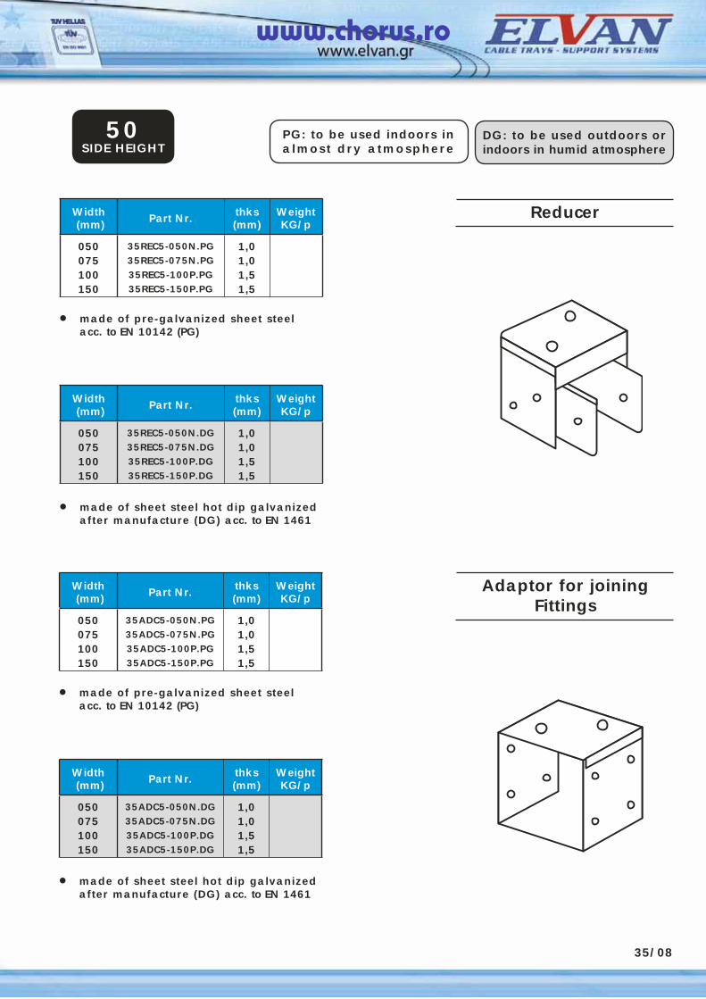
ReducerWidth (mm) Part Nr. thks
(mm)WeightKG/p
050075100150
35REC5-050N.PG35REC5-075N.PG35REC5-100P.PG35REC5-150P.PG
1,01,01,51,5
• made of pre-galvanized sheet steel acc. to EN 10142 (PG)
PG: to be used indoors in almost dry atmosphere
DG: to be used outdoors or indoors in humid atmosphere
50SIDE HEIGHT
Width (mm) Part Nr. thks
(mm)WeightKG/p
050075100150
35REC5-050N.DG35REC5-075N.DG35REC5-100P.DG35REC5-150P.DG
1,01,01,51,5
• made of sheet steel hot dip galvanized after manufacture (DG) acc. to EN 1461
Width (mm) Part Nr. thks
(mm)WeightKG/p
050075100150
35ADC5-050N.PG35ADC5-075N.PG35ADC5-100P.PG35ADC5-150P.PG
1,01,01,51,5
• made of pre-galvanized sheet steel acc. to EN 10142 (PG)
Width (mm) Part Nr. thks
(mm)WeightKG/p
050075100150
35ADC5-050N.DG35ADC5-075N.DG35ADC5-100P.DG35ADC5-150P.DG
1,01,01,51,5
• made of sheet steel hot dip galvanized after manufacture (DG) acc. to EN 1461
Adaptor for joiningFittings
35/08
www.chorus.ro
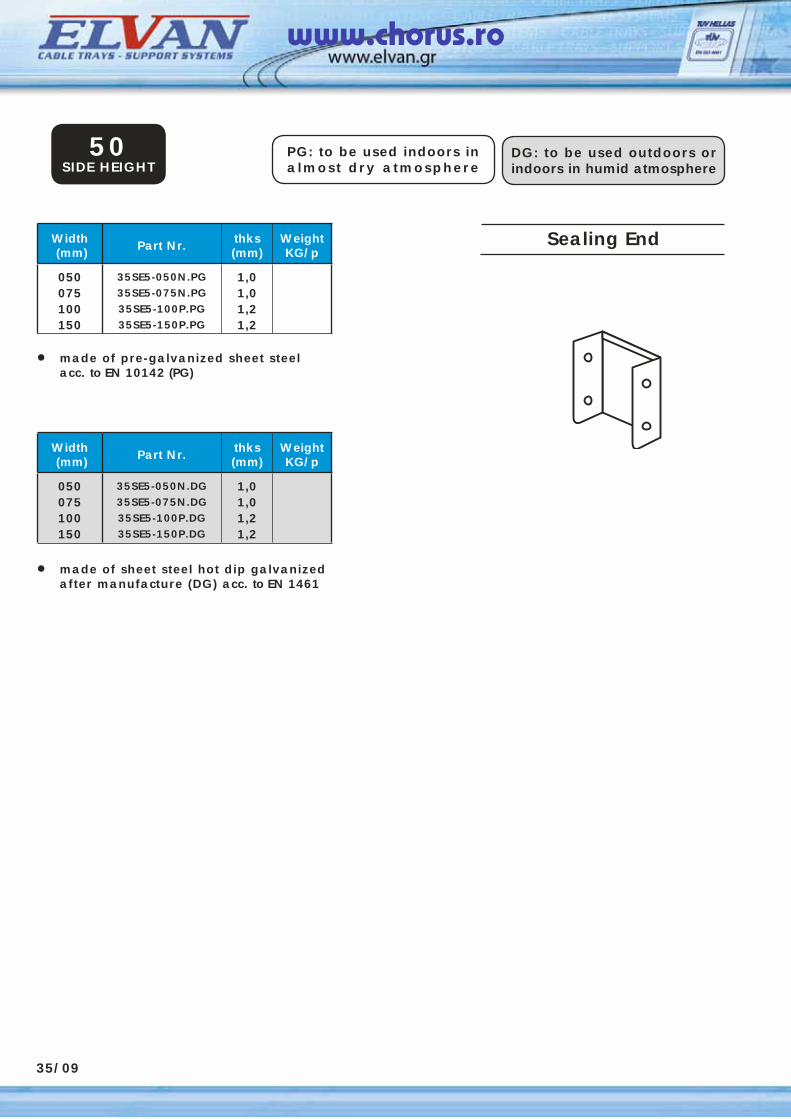
35/09
Sealing EndWidth (mm) Part Nr. thks
(mm)WeightKG/p
050075100150
35SE5-050N.PG35SE5-075N.PG35SE5-100P.PG35SE5-150P.PG
1,01,01,21,2
• made of pre-galvanized sheet steel acc. to EN 10142 (PG)
PG: to be used indoors in almost dry atmosphere
DG: to be used outdoors or indoors in humid atmosphere
50SIDE HEIGHT
Width (mm) Part Nr. thks
(mm)WeightKG/p
050075100150
35SE5-050N.DG35SE5-075N.DG35SE5-100P.DG35SE5-150P.DG
1,01,01,21,2
• made of sheet steel hot dip galvanized after manufacture (DG) acc. to EN 1461
www.chorus.ro
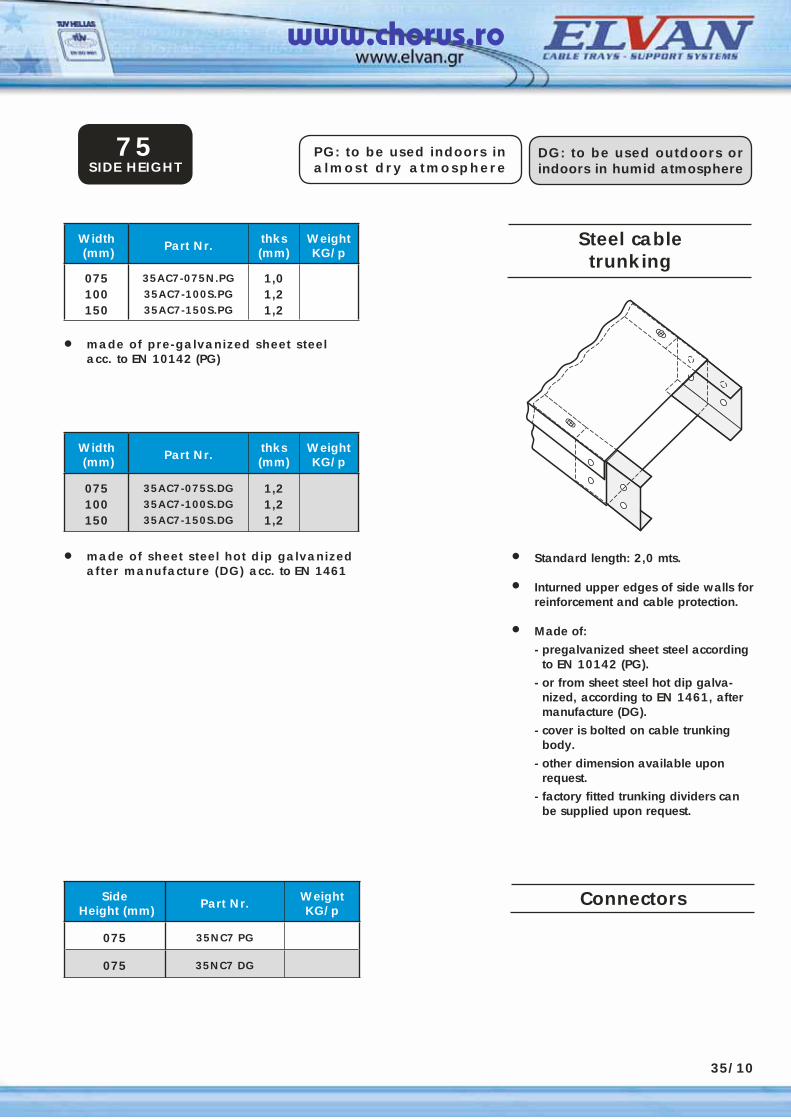
Steel cabletrunking
Width (mm) Part Nr. thks
(mm)WeightKG/p
075100150
35AC7-075N.PG35AC7-100S.PG35AC7-150S.PG
1,01,21,2
• Standard length: 2,0 mts.
• Inturned upper edges of side walls for reinforcement and cable protection.
• Made of:
- pregalvanized sheet steel according to EN 10142 (PG).
- or from sheet steel hot dip galva-nized, according to EN 1461, after manufacture (DG).
- cover is bolted on cable trunking body.
- other dimension available upon request.
- factory fitted trunking dividers can be supplied upon request.
• made of pre-galvanized sheet steel acc. to EN 10142 (PG)
PG: to be used indoors in almost dry atmosphere
DG: to be used outdoors or indoors in humid atmosphere
75SIDE HEIGHT
Width (mm) Part Nr. thks
(mm)WeightKG/p
075100150
35AC7-075S.DG35AC7-100S.DG35AC7-150S.DG
1,21,21,2
• made of sheet steel hot dip galvanized after manufacture (DG) acc. to EN 1461
Side Height (mm) Part Nr. Weight
KG/p
075 35NC7 PG
075 35NC7 DG
35/10
Connectors
www.chorus.ro

Horizontal Bend 90o
Angle (Gusset)Width (mm) Part Nr. thks
(mm)WeightKG/p
075100150
35BKC7-075N.PG35BKC7-100P.PG35BKC7-150P.PG
1,01,51,5
• made of pre-galvanized sheet steel acc. to EN 10142 (PG)
PG: to be used indoors in almost dry atmosphere
DG: to be used outdoors or indoors in humid atmosphere
75SIDE HEIGHT
Width (mm) Part Nr. thks
(mm)WeightKG/p
075100150
35BKC7-075N.DG35BKC7-100P.DG35BKC7-150P.DG
1,01,51,5
• made of sheet steel hot dip galvanized after manufacture (DG) acc. to EN 1461
35/11
Width (mm) Part Nr. thks
(mm)WeightKG/p
075100150
35IBC7-075N.PG35IBC7-100P.PG35IBC7-150P.PG
1,01,51,5
• made of pre-galvanized sheet steel acc. to EN 10142 (PG)
Width (mm) Part Nr. thks
(mm)WeightKG/p
075100150
35IBC7-075N.DG35IBC7-100P.DG35IBC7-150P.DG
1,01,51,5
• made of sheet steel hot dip galvanized after manufacture (DG) acc. to EN 1461
Vertical Bend 90o
Angle (Gusset)
www.chorus.ro
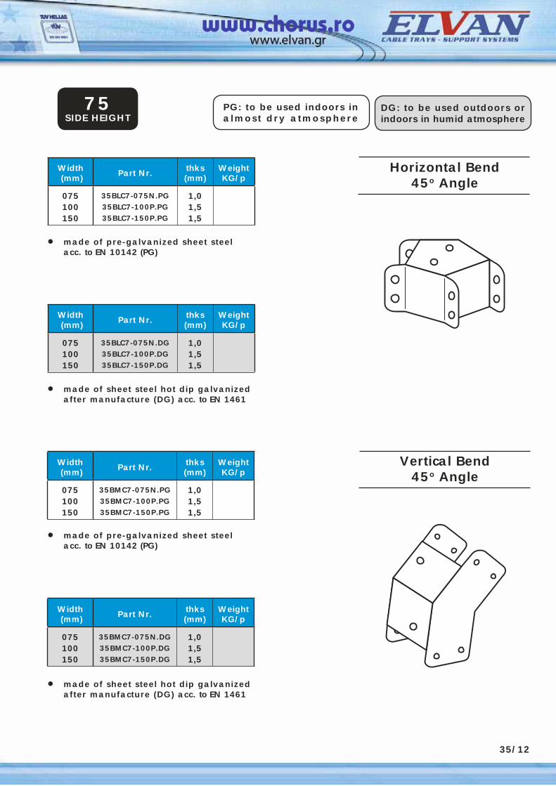
Horizontal Bend45o Angle
Vertical Bend45o Angle
PG: to be used indoors in almost dry atmosphere
DG: to be used outdoors or indoors in humid atmosphere
75SIDE HEIGHT
Width (mm) Part Nr. thks
(mm)WeightKG/p
075100150
35BLC7-075N.PG35BLC7-100P.PG35BLC7-150P.PG
1,01,51,5
• made of pre-galvanized sheet steel acc. to EN 10142 (PG)
Width (mm) Part Nr. thks
(mm)WeightKG/p
075100150
35BLC7-075N.DG35BLC7-100P.DG35BLC7-150P.DG
1,01,51,5
• made of sheet steel hot dip galvanized after manufacture (DG) acc. to EN 1461
Width (mm) Part Nr. thks
(mm)WeightKG/p
075100150
35BMC7-075N.PG35BMC7-100P.PG35BMC7-150P.PG
1,01,51,5
• made of pre-galvanized sheet steel acc. to EN 10142 (PG)
Width (mm) Part Nr. thks
(mm)WeightKG/p
075100150
35BMC7-075N.DG35BMC7-100P.DG35BMC7-150P.DG
1,01,51,5
• made of sheet steel hot dip galvanized after manufacture (DG) acc. to EN 1461
35/12
www.chorus.ro
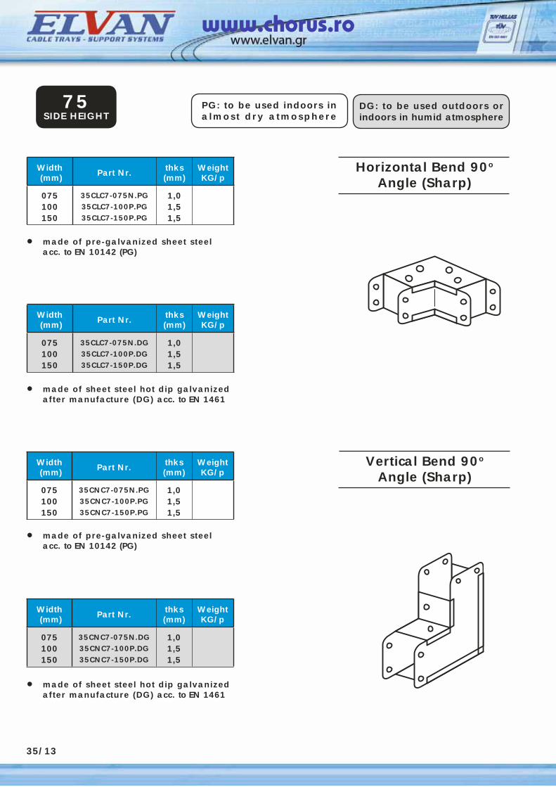
Width (mm) Part Nr. thks
(mm)WeightKG/p
075100150
35CLC7-075N.PG35CLC7-100P.PG35CLC7-150P.PG
1,01,51,5
• made of pre-galvanized sheet steel acc. to EN 10142 (PG)
PG: to be used indoors in almost dry atmosphere
DG: to be used outdoors or indoors in humid atmosphere
75SIDE HEIGHT
Width (mm) Part Nr. thks
(mm)WeightKG/p
075100150
35CLC7-075N.DG35CLC7-100P.DG35CLC7-150P.DG
1,01,51,5
• made of sheet steel hot dip galvanized after manufacture (DG) acc. to EN 1461
35/13
Width (mm) Part Nr. thks
(mm)WeightKG/p
075100150
35CNC7-075N.PG35CNC7-100P.PG35CNC7-150P.PG
1,01,51,5
• made of pre-galvanized sheet steel acc. to EN 10142 (PG)
Width (mm) Part Nr. thks
(mm)WeightKG/p
075100150
35CNC7-075N.DG35CNC7-100P.DG35CNC7-150P.DG
1,01,51,5
• made of sheet steel hot dip galvanized after manufacture (DG) acc. to EN 1461
Horizontal Bend 90o
Angle (Sharp)
Vertical Bend 90o
Angle (Sharp)
www.chorus.ro
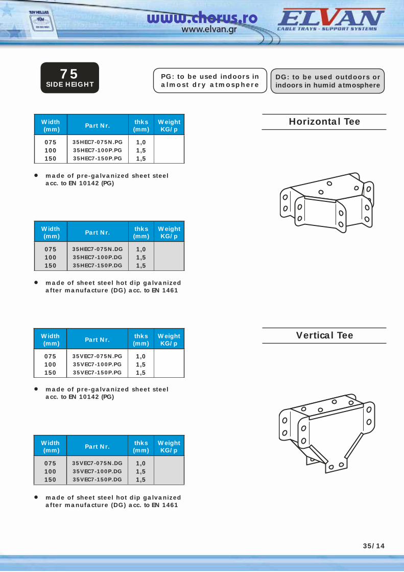
Width (mm) Part Nr. thks
(mm)WeightKG/p
075100150
35HEC7-075N.PG35HEC7-100P.PG35HEC7-150P.PG
1,01,51,5
• made of pre-galvanized sheet steel acc. to EN 10142 (PG)
PG: to be used indoors in almost dry atmosphere
DG: to be used outdoors or indoors in humid atmosphere
75SIDE HEIGHT
Width (mm) Part Nr. thks
(mm)WeightKG/p
075100150
35HEC7-075N.DG35HEC7-100P.DG35HEC7-150P.DG
1,01,51,5
• made of sheet steel hot dip galvanized after manufacture (DG) acc. to EN 1461
35/14
Width (mm) Part Nr. thks
(mm)WeightKG/p
075100150
35VEC7-075N.PG35VEC7-100P.PG35VEC7-150P.PG
1,01,51,5
• made of pre-galvanized sheet steel acc. to EN 10142 (PG)
Width (mm) Part Nr. thks
(mm)WeightKG/p
075100150
35VEC7-075N.DG35VEC7-100P.DG35VEC7-150P.DG
1,01,51,5
• made of sheet steel hot dip galvanized after manufacture (DG) acc. to EN 1461
Horizontal Tee
Vertical Tee
www.chorus.ro
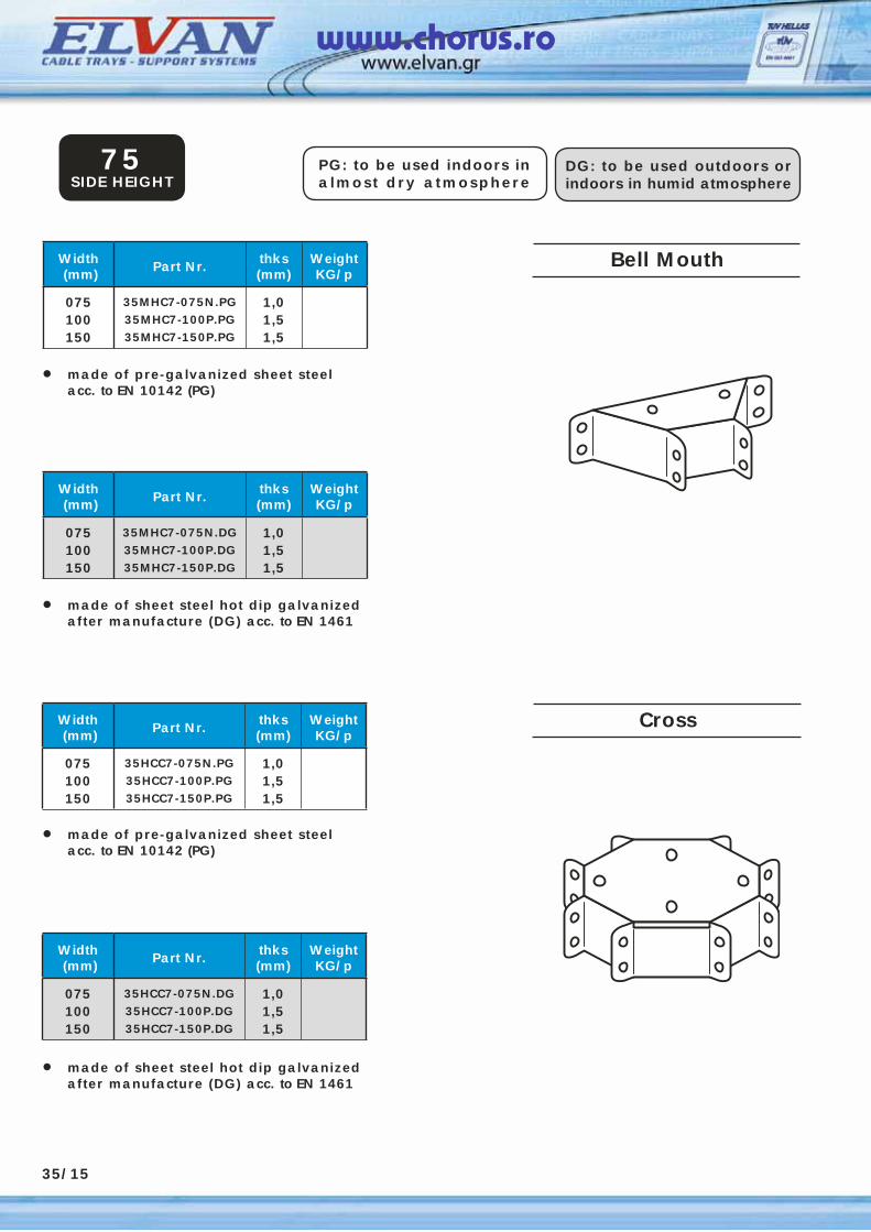
Width (mm) Part Nr. thks
(mm)WeightKG/p
075100150
35MHC7-075N.PG35MHC7-100P.PG35MHC7-150P.PG
1,01,51,5
• made of pre-galvanized sheet steel acc. to EN 10142 (PG)
PG: to be used indoors in almost dry atmosphere
DG: to be used outdoors or indoors in humid atmosphere
75SIDE HEIGHT
Width (mm) Part Nr. thks
(mm)WeightKG/p
075100150
35MHC7-075N.DG35MHC7-100P.DG35MHC7-150P.DG
1,01,51,5
• made of sheet steel hot dip galvanized after manufacture (DG) acc. to EN 1461
35/15
Width (mm) Part Nr. thks
(mm)WeightKG/p
075100150
35HCC7-075N.PG35HCC7-100P.PG35HCC7-150P.PG
1,01,51,5
• made of pre-galvanized sheet steel acc. to EN 10142 (PG)
Width (mm) Part Nr. thks
(mm)WeightKG/p
075100150
35HCC7-075N.DG35HCC7-100P.DG35HCC7-150P.DG
1,01,51,5
• made of sheet steel hot dip galvanized after manufacture (DG) acc. to EN 1461
Bell Mouth
Cross
www.chorus.ro
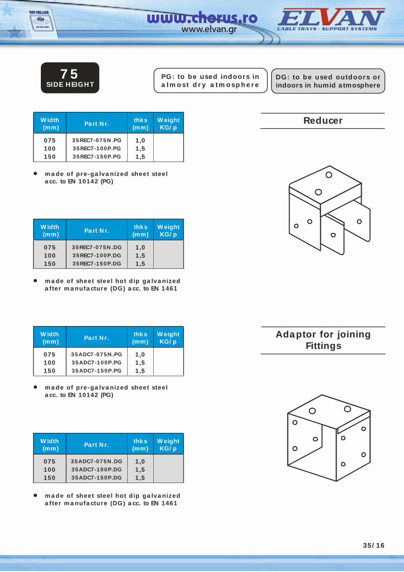
Width (mm) Part Nr. thks
(mm)WeightKG/p
075100150
35REC7-075N.PG35REC7-100P.PG35REC7-150P.PG
1,01,51,5
• made of pre-galvanized sheet steel acc. to EN 10142 (PG)
PG: to be used indoors in almost dry atmosphere
DG: to be used outdoors or indoors in humid atmosphere
75SIDE HEIGHT
Width (mm) Part Nr. thks
(mm)WeightKG/p
075100150
35REC7-075N.DG35REC7-100P.DG35REC7-150P.DG
1,01,51,5
• made of sheet steel hot dip galvanized after manufacture (DG) acc. to EN 1461
35/16
Width (mm) Part Nr. thks
(mm)WeightKG/p
075100150
35ADC7-075N.PG35ADC7-100P.PG35ADC7-150P.PG
1,01,51,5
• made of pre-galvanized sheet steel acc. to EN 10142 (PG)
Width (mm) Part Nr. thks
(mm)WeightKG/p
075100150
35ADC7-075N.DG35ADC7-100P.DG35ADC7-150P.DG
1,01,51,5
• made of sheet steel hot dip galvanized after manufacture (DG) acc. to EN 1461
Reducer
Adaptor for joiningFittings
www.chorus.ro
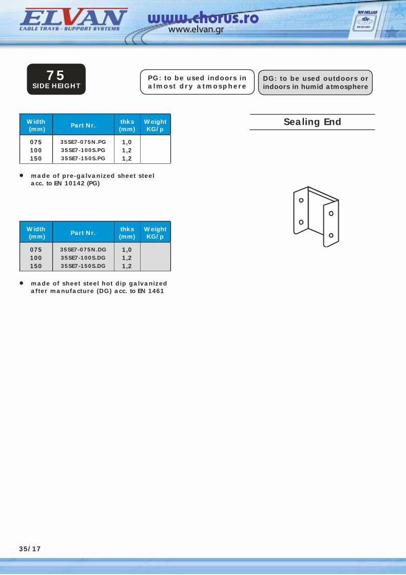
Width (mm) Part Nr. thks
(mm)WeightKG/p
075100150
35SE7-075N.PG35SE7-100S.PG35SE7-150S.PG
1,01,21,2
• made of pre-galvanized sheet steel acc. to EN 10142 (PG)
PG: to be used indoors in almost dry atmosphere
DG: to be used outdoors or indoors in humid atmosphere
75SIDE HEIGHT
Width (mm) Part Nr. thks
(mm)WeightKG/p
075100150
35SE7-075N.DG35SE7-100S.DG35SE7-150S.DG
1,01,21,2
• made of sheet steel hot dip galvanized after manufacture (DG) acc. to EN 1461
35/17
Sealing End
www.chorus.ro
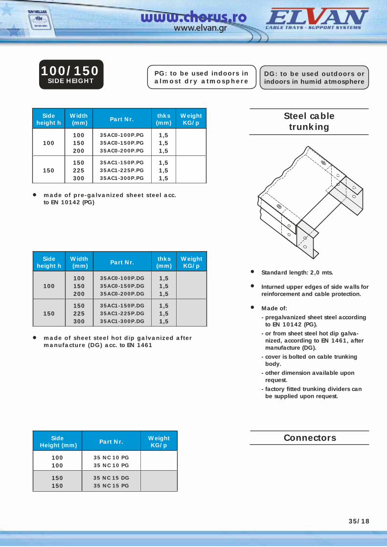
Steel cabletrunking
Sideheight h
Width (mm) Part Nr. thks
(mm)WeightKG/p
100100150200
35AC0-100P.PG35AC0-150P.PG35AC0-200P.PG
1,51,51,5
150150225300
35AC1-150P.PG35AC1-225P.PG35AC1-300P.PG
1,51,51,5
• Standard length: 2,0 mts.
• Inturned upper edges of side walls for reinforcement and cable protection.
• Made of:
- pregalvanized sheet steel according to EN 10142 (PG).
- or from sheet steel hot dip galva-nized, according to EN 1461, after manufacture (DG).
- cover is bolted on cable trunking body.
- other dimension available upon request.
- factory fitted trunking dividers can be supplied upon request.
• made of pre-galvanized sheet steel acc. to EN 10142 (PG)
PG: to be used indoors in almost dry atmosphere
DG: to be used outdoors or indoors in humid atmosphere
100/150SIDE HEIGHT
• made of sheet steel hot dip galvanized after manufacture (DG) acc. to EN 1461
Side Height (mm) Part Nr. Weight
KG/p
100100
35 NC 10 PG35 NC 10 PG
150150
35 NC 15 DG35 NC 15 PG
35/18
Sideheight h
Width (mm) Part Nr. thks
(mm)WeightKG/p
100100150200
35AC0-100P.DG35AC0-150P.DG35AC0-200P.DG
1,51,51,5
150150225300
35AC1-150P.DG35AC1-225P.DG35AC1-300P.DG
1,51,51,5
Connectors
www.chorus.ro
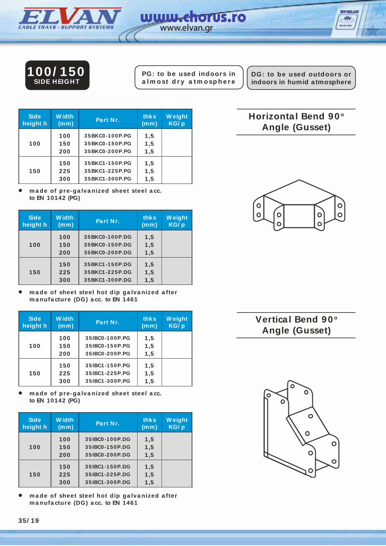
Horizontal Bend 90o
Angle (Gusset)
PG: to be used indoors in almost dry atmosphere
DG: to be used outdoors or indoors in humid atmosphere
Vertical Bend 90o
Angle (Gusset)
Sideheight h
Width (mm) Part Nr. thks
(mm)WeightKG/p
100100150200
35BKC0-100P.PG35BKC0-150P.PG35BKC0-200P.PG
1,51,51,5
150150225300
35BKC1-150P.PG35BKC1-225P.PG35BKC1-300P.PG
1,51,51,5
• made of pre-galvanized sheet steel acc. to EN 10142 (PG)
100/150SIDE HEIGHT
• made of sheet steel hot dip galvanized after manufacture (DG) acc. to EN 1461
Sideheight h
Width (mm) Part Nr. thks
(mm)WeightKG/p
100100150200
35BKC0-100P.DG35BKC0-150P.DG35BKC0-200P.DG
1,51,51,5
150150225300
35BKC1-150P.DG35BKC1-225P.DG35BKC1-300P.DG
1,51,51,5
35/19
Sideheight h
Width (mm) Part Nr. thks
(mm)WeightKG/p
100100150200
35IBC0-100P.PG35IBC0-150P.PG35IBC0-200P.PG
1,51,51,5
150150225300
35IBC1-150P.PG35IBC1-225P.PG35IBC1-300P.PG
1,51,51,5
• made of pre-galvanized sheet steel acc. to EN 10142 (PG)
• made of sheet steel hot dip galvanized after manufacture (DG) acc. to EN 1461
Sideheight h
Width (mm) Part Nr. thks
(mm)WeightKG/p
100100150200
35IBC0-100P.DG35IBC0-150P.DG35IBC0-200P.DG
1,51,51,5
150150225300
35IBC1-150P.DG35IBC1-225P.DG35IBC1-300P.DG
1,51,51,5
www.chorus.ro
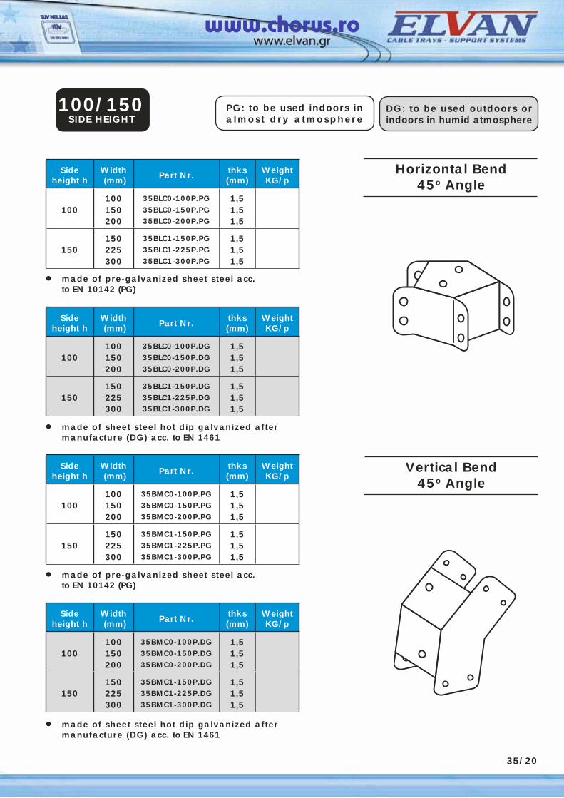
PG: to be used indoors in almost dry atmosphere
DG: to be used outdoors or indoors in humid atmosphere
Sideheight h
Width (mm) Part Nr. thks
(mm)WeightKG/p
100100150200
35BLC0-100P.PG35BLC0-150P.PG35BLC0-200P.PG
1,51,51,5
150150225300
35BLC1-150P.PG35BLC1-225P.PG35BLC1-300P.PG
1,51,51,5
• made of pre-galvanized sheet steel acc. to EN 10142 (PG)
100/150SIDE HEIGHT
• made of sheet steel hot dip galvanized after manufacture (DG) acc. to EN 1461
Sideheight h
Width (mm) Part Nr. thks
(mm)WeightKG/p
100100150200
35BLC0-100P.DG35BLC0-150P.DG35BLC0-200P.DG
1,51,51,5
150150225300
35BLC1-150P.DG35BLC1-225P.DG35BLC1-300P.DG
1,51,51,5
Sideheight h
Width (mm) Part Nr. thks
(mm)WeightKG/p
100100150200
35BMC0-100P.PG35BMC0-150P.PG35BMC0-200P.PG
1,51,51,5
150150225300
35BMC1-150P.PG35BMC1-225P.PG35BMC1-300P.PG
1,51,51,5
• made of pre-galvanized sheet steel acc. to EN 10142 (PG)
• made of sheet steel hot dip galvanized after manufacture (DG) acc. to EN 1461
Sideheight h
Width (mm) Part Nr. thks
(mm)WeightKG/p
100100150200
35BMC0-100P.DG35BMC0-150P.DG35BMC0-200P.DG
1,51,51,5
150150225300
35BMC1-150P.DG35BMC1-225P.DG35BMC1-300P.DG
1,51,51,5
35/20
Horizontal Bend45o Angle
Vertical Bend45o Angle
www.chorus.ro
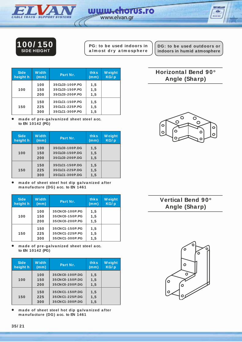
PG: to be used indoors in almost dry atmosphere
DG: to be used outdoors or indoors in humid atmosphere
Sideheight h
Width (mm) Part Nr. thks
(mm)WeightKG/p
100100150200
35CLC0-100P.PG35CLC0-150P.PG35CLC0-200P.PG
1,51,51,5
150150225300
35CLC1-150P.PG35CLC1-225P.PG35CLC1-300P.PG
1,51,51,5
• made of pre-galvanized sheet steel acc. to EN 10142 (PG)
100/150SIDE HEIGHT
• made of sheet steel hot dip galvanized after manufacture (DG) acc. to EN 1461
Sideheight h
Width (mm) Part Nr. thks
(mm)WeightKG/p
100100150200
35CLC0-100P.DG35CLC0-150P.DG35CLC0-200P.DG
1,51,51,5
150150225300
35CLC1-150P.DG35CLC1-225P.DG35CLC1-300P.DG
1,51,51,5
Sideheight h
Width (mm) Part Nr. thks
(mm)WeightKG/p
100100150200
35CNC0-100P.PG35CNC0-150P.PG35CNC0-200P.PG
1,51,51,5
150150225300
35CNC1-150P.PG35CNC1-225P.PG35CNC1-300P.PG
1,51,51,5
• made of pre-galvanized sheet steel acc. to EN 10142 (PG)
• made of sheet steel hot dip galvanized after manufacture (DG) acc. to EN 1461
Sideheight h
Width (mm) Part Nr. thks
(mm)WeightKG/p
100100150200
35CNC0-100P.DG35CNC0-150P.DG35CNC0-200P.DG
1,51,51,5
150150225300
35CNC1-150P.DG35CNC1-225P.DG35CNC1-300P.DG
1,51,51,5
35/21
Horizontal Bend 90o
Angle (Sharp)
Vertical Bend 90o
Angle (Sharp)
www.chorus.ro
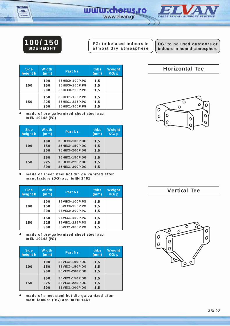
PG: to be used indoors in almost dry atmosphere
DG: to be used outdoors or indoors in humid atmosphere
Sideheight h
Width (mm) Part Nr. thks
(mm)WeightKG/p
100100150200
35HEC0-100P.PG35HEC0-150P.PG35HEC0-200P.PG
1,51,51,5
150150225300
35HEC1-150P.PG35HEC1-225P.PG35HEC1-300P.PG
1,51,51,5
• made of pre-galvanized sheet steel acc. to EN 10142 (PG)
100/150SIDE HEIGHT
• made of sheet steel hot dip galvanized after manufacture (DG) acc. to EN 1461
Sideheight h
Width (mm) Part Nr. thks
(mm)WeightKG/p
100100150200
35HEC0-100P.DG35HEC0-150P.DG35HEC0-200P.DG
1,51,51,5
150150225300
35HEC1-150P.DG35HEC1-225P.DG35HEC1-300P.DG
1,51,51,5
Sideheight h
Width (mm) Part Nr. thks
(mm)WeightKG/p
100100150200
35VEC0-100P.PG35VEC0-150P.PG35VEC0-200P.PG
1,51,51,5
150150225300
35VEC1-150P.PG35VEC1-225P.PG35VEC1-300P.PG
1,51,51,5
• made of pre-galvanized sheet steel acc. to EN 10142 (PG)
• made of sheet steel hot dip galvanized after manufacture (DG) acc. to EN 1461
Sideheight h
Width (mm) Part Nr. thks
(mm)WeightKG/p
100100150200
35VEC0-100P.DG35VEC0-150P.DG35VEC0-200P.DG
1,51,51,5
150150225300
35VEC1-150P.DG35VEC1-225P.DG35VEC1-300P.DG
1,51,51,5
35/22
Horizontal Tee
Vertical Tee
www.chorus.ro
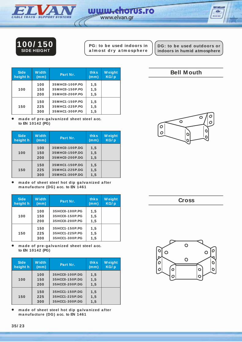
PG: to be used indoors in almost dry atmosphere
DG: to be used outdoors or indoors in humid atmosphere
Sideheight h
Width (mm) Part Nr. thks
(mm)WeightKG/p
100100150200
35MHC0-100P.PG35MHC0-150P.PG35MHC0-200P.PG
1,51,51,5
150150225300
35MHC1-150P.PG35MHC1-225P.PG35MHC1-300P.PG
1,51,51,5
• made of pre-galvanized sheet steel acc. to EN 10142 (PG)
100/150SIDE HEIGHT
• made of sheet steel hot dip galvanized after manufacture (DG) acc. to EN 1461
Sideheight h
Width (mm) Part Nr. thks
(mm)WeightKG/p
100100150200
35MHC0-100P.DG35MHC0-150P.DG35MHC0-200P.DG
1,51,51,5
150150225300
35MHC1-150P.DG35MHC1-225P.DG35MHC1-300P.DG
1,51,51,5
Sideheight h
Width (mm) Part Nr. thks
(mm)WeightKG/p
100100150200
35HCC0-100P.PG35HCC0-150P.PG35HCC0-200P.PG
1,51,51,5
150150225300
35HCC1-150P.PG35HCC1-225P.PG35HCC1-300P.PG
1,51,51,5
• made of pre-galvanized sheet steel acc. to EN 10142 (PG)
• made of sheet steel hot dip galvanized after manufacture (DG) acc. to EN 1461
Sideheight h
Width (mm) Part Nr. thks
(mm)WeightKG/p
100100150200
35HCC0-100P.DG35HCC0-150P.DG35HCC0-200P.DG
1,51,51,5
150150225300
35HCC1-150P.DG35HCC1-225P.DG35HCC1-300P.DG
1,51,51,5
35/23
Bell Mouth
Cross
www.chorus.ro
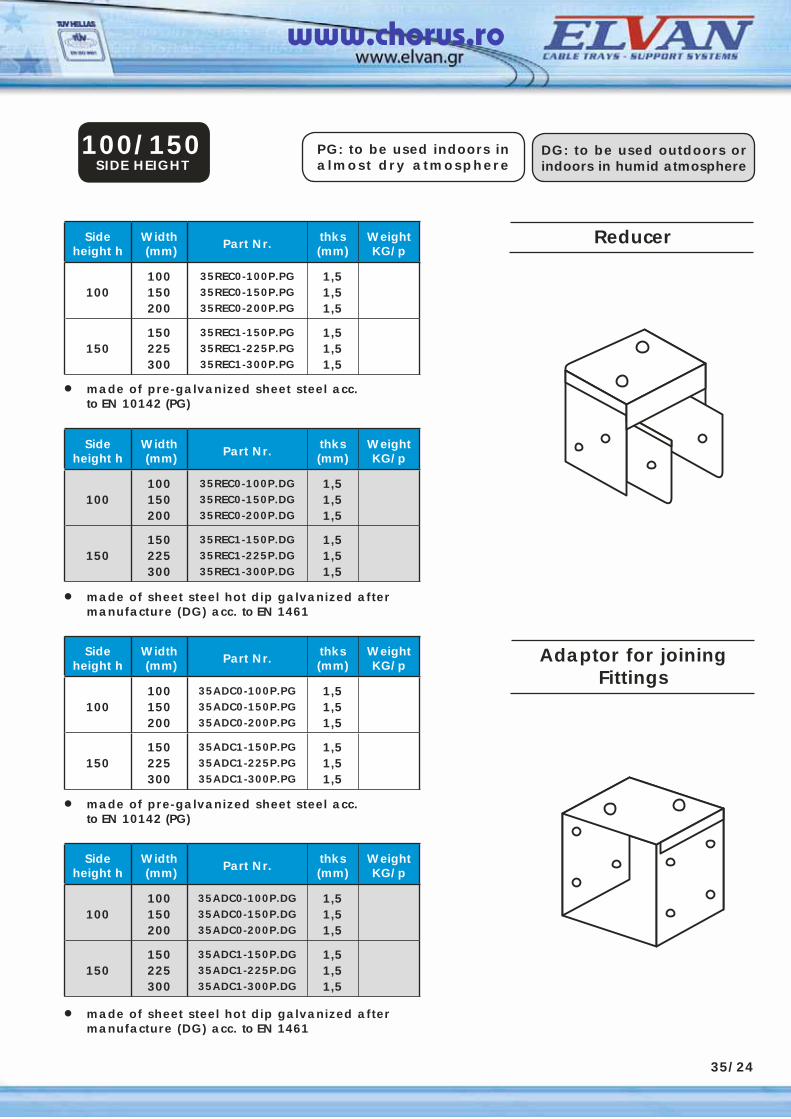
Sideheight h
Width (mm) Part Nr. thks
(mm)WeightKG/p
100100150200
35REC0-100P.PG35REC0-150P.PG35REC0-200P.PG
1,51,51,5
150150225300
35REC1-150P.PG35REC1-225P.PG35REC1-300P.PG
1,51,51,5
• made of pre-galvanized sheet steel acc. to EN 10142 (PG)
100/150SIDE HEIGHT
• made of sheet steel hot dip galvanized after manufacture (DG) acc. to EN 1461
Sideheight h
Width (mm) Part Nr. thks
(mm)WeightKG/p
100100150200
35REC0-100P.DG35REC0-150P.DG35REC0-200P.DG
1,51,51,5
150150225300
35REC1-150P.DG35REC1-225P.DG35REC1-300P.DG
1,51,51,5
Sideheight h
Width (mm) Part Nr. thks
(mm)WeightKG/p
100100150200
35ADC0-100P.PG35ADC0-150P.PG35ADC0-200P.PG
1,51,51,5
150150225300
35ADC1-150P.PG35ADC1-225P.PG35ADC1-300P.PG
1,51,51,5
• made of pre-galvanized sheet steel acc. to EN 10142 (PG)
• made of sheet steel hot dip galvanized after manufacture (DG) acc. to EN 1461
Sideheight h
Width (mm) Part Nr. thks
(mm)WeightKG/p
100100150200
35ADC0-100P.DG35ADC0-150P.DG35ADC0-200P.DG
1,51,51,5
150150225300
35ADC1-150P.DG35ADC1-225P.DG35ADC1-300P.DG
1,51,51,5
35/24
Reducer
Adaptor for joiningFittings
PG: to be used indoors in almost dry atmosphere
DG: to be used outdoors or indoors in humid atmosphere
www.chorus.ro
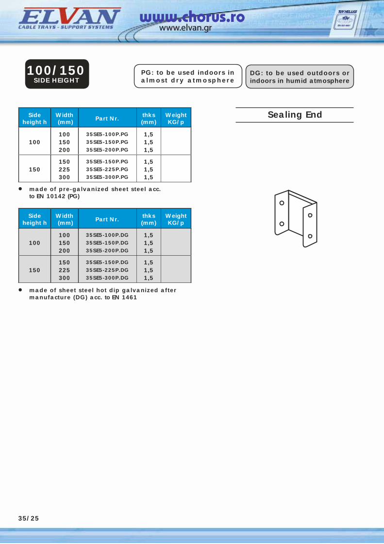
PG: to be used indoors in almost dry atmosphere
DG: to be used outdoors or indoors in humid atmosphere
Sideheight h
Width (mm) Part Nr. thks
(mm)WeightKG/p
100100150200
35SE5-100P.PG35SE5-150P.PG35SE5-200P.PG
1,51,51,5
150150225300
35SE5-150P.PG35SE5-225P.PG35SE5-300P.PG
1,51,51,5
• made of pre-galvanized sheet steel acc. to EN 10142 (PG)
100/150SIDE HEIGHT
• made of sheet steel hot dip galvanized after manufacture (DG) acc. to EN 1461
Sideheight h
Width (mm) Part Nr. thks
(mm)WeightKG/p
100100150200
35SE5-100P.DG35SE5-150P.DG35SE5-200P.DG
1,51,51,5
150150225300
35SE5-150P.DG35SE5-225P.DG35SE5-300P.DG
1,51,51,5
35/25
Sealing End
www.chorus.ro