Embed Size (px)
Citation preview

A27
Catalog HY03-1800-2US
Parker Pneumatic
Parker Hannifin CorporationPneumatic DivisionWadsworth, Ohiowww.parker.com/pneu/rotary
A
Ra
ck
& P
inio
n
Actu
ato
rs
HU
B
Se
rie
s
LT
R
Se
rie
s
HT
R
Se
rie
s
M
Se
rie
s
Market Segments and Applications A28
Features A29
Ordering Information A30-A31
Specifications A32
Engineering Data A33-A35
Dimensional Data A36
Options
Three-Position Actuator A37
Antibacklash Actuator A38
Port Threads, Port Location A39
Cushions A40
Stroke Adjusters A41
Port Flow Controls A41
Mounting A42
Shaft A43
Magnetic Piston A44
Shaft Seal Cover A44
Seals, Feedback A45
Proximity Sensors A46
Hydraulic Rotary Actuators, LTR Series
Contents
LTR Series
Light Duty Hydraulic
Rack & Pinion Rotary Actuators

A28
Catalog HY03-1800-2US
Parker Pneumatic
Parker Hannifin CorporationPneumatic DivisionWadsworth, Ohiowww.parker.com/pneu/rotary
A
Ra
ck
& P
inio
n
Actu
ato
rs
HU
B
Se
rie
s
LT
R
Se
rie
s
HT
R
Se
rie
s
M
Se
rie
s
Hydraulic Rotary Actuators, LTR Series
Market Segment & Applications
Product Series
Market/Segment Typical Application(s) HUB LTR HTR M Tork-Mor
Ma
rke
t S
eg
me
nts
/Ap
plic
ati
on
s
Aerospace Water bomb, tank door actuation •Aggregate Granite block rollover •Aluminum Automation •Automation
Mounting, Processing, Flood gate
actuation, End of arm tooling • • • •Automotive
Automation, Clamping, Tube
bending • •Conveyor Swing & rotate • • •Entertaining
Pool gate actuation, Robotic joint
motion •Fluid Management &
Flow ControlPower plants • •
Industrial Automation, Clamping •Machine Builders End of arm tooling •Marine/Offshore Boomslewer, Submersible • •Mining
Mobile longhole drilling, Tunnel
boring • • •
Mobile
Fire truck ladder rotation, Aerial
lift basket, X-ray boom rotation,
Forklift handling & storage, Refuse
tippers
• • • •
Nuclear Door actuation •Oil & Gas Process valve actuation • •Oil Industry Machinery Clamping, Lockout • •Paper & Pulp Walking beam •Plastics Blow molding, Injection molding • •Rubber Mixing • •Solar Panel rotation •Space Rocket launch tower •Steel & Casting
Ladle Tilt, Coil Box, Steel Booming,
Pipe fabrication • • •Testing Equipment
Flight Simulators, Cycle loading,
Tensile test Machines • •Transportation Bus wheelchair ramp •Water Management • •Welding Weld gun indexing, Clamping •

A29
Catalog HY03-1800-2US
Parker Pneumatic
Parker Hannifin CorporationPneumatic DivisionWadsworth, Ohiowww.parker.com/pneu/rotary
A
Ra
ck
& P
inio
n
Actu
ato
rs
HU
B
Se
rie
s
LT
R
Se
rie
s
HT
R
Se
rie
s
M
Se
rie
s
BALL BEARINGS are
generously sized to support
large (relative to actuator's
weight) external axial and
radial loads.
PISTON SEALS
Heavy duty, deep section Polypak
seals made from Molythane
for dependable service in most
applications. Options: Fluorocarbon
seals for certain synthetic fluids;
and carboxylated nitrile seals for
water based fluids. Piston seals
can be inspected and replaced
without disconnecting the load from
the shaft. (Employ proper safety
practices to prevent damage to
people or equipment.)
KEYWAY mid stroke
at 12:00 position is
standard.
OPTIONAL CUSHIONS
If properly adjusted, cushions can serve
as a braking device for most industrial
applications. The proven Parker "floating
cushion bushing" serves as a high
performance check valve for "quick
get away" and the needle valve can be
adjusted to regulate the exhaust flow from
the piston. Our design uses no springs or
check valve seats that can break under
normal usage.
RACK & PINION made
from through hardened, high
strength alloy steels for long
and durable service life in most
applications.
HOUSING
High strength housing
serves as a firm base
to drive large torque
requirements.
THREADED MOUNTING HOLES
Our standard mounting has four bolt
holes drilled and tapped on the front
and back of the housing. Options:
pilot ring or base mount.
STANDARD MALE KEYED
SHAFT is made integral with
the pinion gear and is suitable
for most applications. Options:
double male key, hollow bore
keyed and splined shafts are
available.
Hydraulic Rotary Actuators, LTR Series
Features
LTR Series

A30
Catalog HY03-1800-2US
Parker Pneumatic
Parker Hannifin CorporationPneumatic DivisionWadsworth, Ohiowww.parker.com/pneu/rotary
A
Ra
ck
& P
inio
n
Actu
ato
rs
HU
B
Se
rie
s
LT
R
Se
rie
s
HT
R
Se
rie
s
M
Se
rie
s
Hydraulic Rotary Actuators, LTR Series
Ordering Information - Inch
Notes:
1 For 3-position units, specify middle and
total rotation separated by a "/",
ie 045/180.
* Viewed from shaft end
** Double rack models only
^ Reduces to 10° with cushions
∆ For use with standard male shafts only
LTR 25 1 090 3 F P– – A B 2 1 M V – C
Ordering information – Inch
Special Options
Omit Standard
Two or three-digit code assigned by factory and applies when any “X” or “9” appears in the model number or when special options or features are required.
Design series
C Current
Seals
Omit Nitrile (standard)
V Fluorocarbon
W Carboxylated nitrile
X Special
Port flow controls
Omit None
PFlow control both rotations
RFlow control CW rotation *
SFlow control CCW rotation * Standard options
Omit None
H Resolver feedback
J Potentiometer
M Magnetic piston ring
S Shaft seal cover ∆
Port location
1 Position 1 (standard)
2 Position 2
3 Position 3
4 Position 4
9 Special
Port threads
1 SAE straight thread (standard)
2 NPTF
9 Special
Other options
Detail in clear text:
Proximity switches – Specify high or low range, rotation direction.
Mounting
AFace/base (standard)
F Front flange
G Foot flange
P Pilot ring
R Rear flange
X Special
Shaft
A Female keyed
BSingle male keyed (standard)
C Double male keyed
R Preload keyway
X Special
Model
10 1" bore
15 1-1/2" bore
20 2" bore
25 2-1/2" bore
32 3-1/4" bore
Configuration
1 Single rack
2 Double rack
3 Three position actuator
7 Antibacklash
Cushions
Omit None
1 Cushioned CW rotation *
2 Cushioned CCW rotation *
3 Cushioned both rotations
4 Four cushions **
8 High performance cushion **
9 Special
Stroke adjusters
Omit None
D 0-30° CW rotation *^
E 0-30° CCW rotation *^
F 0-30° both rotations *^
X Special
Rotation 1
090 90°
180 180°
270 270°
360 360°
Or specify any other rotation.

A31
Catalog HY03-1800-2US
Parker Pneumatic
Parker Hannifin CorporationPneumatic DivisionWadsworth, Ohiowww.parker.com/pneu/rotary
A
Ra
ck
& P
inio
n
Actu
ato
rs
HU
B
Se
rie
s
LT
R
Se
rie
s
HT
R
Se
rie
s
M
Se
rie
s
Hydraulic Rotary Actuators, LTR Series
Ordering Information - Metric
Notes:
1 For 3-position units, specify middle and
total rotation separated by a "/",
ie 045/180.
* Viewed from shaft end
** Double rack models only
◊ Not available on Size 32
^ Reduces to 10° with cushions
∆ For use with male shafts only
LTR 25 1 090 3 F P– – B D 4 1 M V – C
Ordering information – Metric
Special Options
Omit Standard
Two or three-digit code assigned by factory and applies when any “X” or “9” appears in the model number or when special options or features are required.
Design series
C Current
Seals
Omit Nitrile (standard)
V Fluorocarbon
W Carboxylated nitrile
X Special
Port flow controls
Omit None
PFlow control both rotations
RFlow control CW rotation *
SFlow control CCW rotation *
Standard options
Omit None
H Resolver feedback
J Potentiometer
M Magnetic piston ring
S Shaft seal cover ∆
Port location
1 Position 1 (standard)
2 Position 2
3 Position 3
4 Position 4
9 Special
Port threads
4 BSPP (standard)
5 DIN 3852/1
6 ISO 6149/1
1 SAE straight thread
2 NPTF
9 SpecialOther options
Detail in clear text:
Proximity switches – Specify high or low range, rotation direction.
Mounting
BFace/base (standard)
H Front flange
K Foot flange ◊
S Pilot ring
T Rear flange
X Special
Shaft
DSingle male keyed (standard)
E Female keyed
F Double male keyed
X Special
Model
10 1" (25.4mm) bore
15 1-1/2" (38.1mm) bore
20 2" (50.8mm) bore
25 2-1/2" (63.5mm) bore
32 3-1/4" (82.6mm) bore
Configuration
1 Single rack
2 Double rack
3 Three position actuator
7 Antibacklash
Cushions
Omit None
1 Cushioned CW rotation *
2 Cushioned CCW rotation *
3 Cushioned both rotations
4 Four cushions **
8 High performance cushion **
9 Special
Stroke adjusters
Omit None
D 0-30° CW rotation *^
E 0-30° CCW rotation *^
F 0-30° both rotations *^
X Special
Rotation 1
090 90°
180 180°
270 270°
360 360°
Or specify any other rotation.

A32
Catalog HY03-1800-2US
Parker Pneumatic
Parker Hannifin CorporationPneumatic DivisionWadsworth, Ohiowww.parker.com/pneu/rotary
A
Ra
ck
& P
inio
n
Actu
ato
rs
HU
B
Se
rie
s
LT
R
Se
rie
s
HT
R
Se
rie
s
M
Se
rie
s
The LTR series rotary actuator is ideal for low pressure
hydraulic applications. The LTR Series actuator combines
an alloy steel gear set with a high strength aluminum
housing and Parker 3L or 2A Series cylinder components
into an actuator suitable for years of trouble free service.
The actuator maximizes volumetric efficiency by using
self-energizing PolyPak seals. Mechanical efficiency is
maximized by using antifriction bearings and Wear-pak®
piston technology.
•Hydraulic cushions to minimize noise, vibration shock
and assist deceleration control
•Reed, Hall Effect or proximity switches for position
sensing
•End-of-rotation stroke adjusters for load position control
and accurate rotation adjustment
•Built-in meter outflow control valves with reverse flow
check valves provide a neat package
•Three position option can be used with many special
machine and material handling applications
Specifications
Single
rack
Double
rack2
Theoretical output torque1, in-lb
versus input pressure, PSI (bar)
Gear train rating
pitting life estimate
1 million cycles
Displacement
per degree of
rotation
Maximum
angular
backlash
Maximum
rotational
tolerance
100
(7)
250
(17)
500
(34)
750
(52)
1000
(69)
1500
(103) inch-lbf3 PSID4 in3/deg. Minutes Degrees
101 39 98 197 295 395 592 270 800 0.007 60 -0/+5
102 79 197 395 592 – – 580 800 0.014 60 -0/+5
151 118 294 590 885 1180 1770 665 650 0.021 45 -0/+4
152 236 590 1180 1770 2360 3530 1400 650 0.042 45 -0/+4
201 282 705 1410 2115 2830 4240 1790 750 0.049 35 -0/+3
251 430 1074 2148 3222 4295 6443 2100 550 0.075 35 -0/+3
202 565 1410 2820 4230 5650 8470 3790 750 0.099 35 -0/+3
252 859 2148 4295 6442 8590 12885 4250 550 0.150 35 -0/+3
321 1141 2852 5703 8554 11407 – 3880 400 0.199 25 -0/+2
322 2281 5703 11407 17110 22813 – 6160 300 0.398 25 -0/+2
1. As a precaution, consult factory whenever using the LTR with port flow controls, cushions, or stroke adjusters on double rack units. These options
may require the units to be pressure derated.
2. Double rack actuators should specify type 4 or 8 cushions and four stroke adjusters and four flow controls (one per end cap) to balance the gear
tooth forces on the pinion. Contact the factory for ordering code information. Type 1, 2, or 3 cushions, type A, B, or C stroke adjusters and type
P, R, and S port flow controls may cause a destructive bending couple upon the pinion gear under some operating conditions.
3. Durability rated output torque.
4. Pressure differential between the inlet and outlet ports (non-shock).
5. Reduce LTR Series pressure rating by 50% when specifying a magnetic piston with aluminum cylinder tubes, option “M” except on LTR101 and
102 models, or when a unit has cushions.
Hydraulic Rotary Actuators, LTR Series
Specifications
Operating information
Output Torques 1000 psi (69 bar): 395 in-lb to
22,813 in-lb
Nominal pressure: 1000 PSIG (69 bar)
(3L cylinder pressure ratings apply)
Operating temperature range:
Nitrile seals -40°F to 180°F (-40°C to 82°C)
Flurocarbon seals -20°F to 250°F (-29°C to 121°C)
Standard rotations: 90°, 180°, 270°, 360°, 450°
Rotational tolerance -0°, +2°
Breakaway pressure: 30 PSIG (2 bar) maximum
Mounting orientation: unrestricted
Standard timing: Keyway in 12:00 position at
midstroke
Recommended filtration: ISO class 17/14 or better

A33
Catalog HY03-1800-2US
Parker Pneumatic
Parker Hannifin CorporationPneumatic DivisionWadsworth, Ohiowww.parker.com/pneu/rotary
A
Ra
ck
& P
inio
n
Actu
ato
rs
HU
B
Se
rie
s
LT
R
Se
rie
s
HT
R
Se
rie
s
M
Se
rie
s
SUPPLEMENTAL INFORMATION
KINETIC ENERGY BASIC FORMULA
KE = 1/2 Jmω2
ω = 0.0175 x
Bearing Load Capacities & Gear Train Available
2ΘA + ΘC + 2ΘD
Rotation Time (sec.)
Cushion Deceleration Control
where:
KE = Kinetic Energy (in-lb)
Jm = Rotational Mass Moment of Inertia (in-lb-sec2)
See Page 8 for formulas.
ω = Peak Velocity (rad/sec)
(Assuming trapezoidal velocity profile)
ΘA = Acceleration Angle (deg)
ΘC = Constant Velocity Angle (deg)
ΘD = Deceleration Angle (deg)
The cushion causes the resisting torque that can be
used to decelerate a rotational load. Please note the
cushion has to provide enough resistance to control:
drive torque caused by the hydraulic system pressure;
plus the torque caused by gravity pulling on the
rotational load; and the kinetic energy associated with
the motion of the inertia load. Since the actuator's
cushion has to be able to control the sum of all three
torque factors, we suggest including cushion capacity
as one of the actuator selection criteria.
It is strongly suggested that proportional valves be used
instead of cushions to control (decelerate) high inertial
loads. This provides the ability to reduce inlet pressure
while generating deceleration pressure. It also allows for
longer ramp times, thus increasing deceleration stroke.
Model
Bearing load capacities* Distance Available stopping work per endcap / cushion**
Radial Thrust between bearings Strength criteria Durability criteria
lb kN lb kN inch mm in-lb Nm in-lb Nm
10 100 0.4 50 0.2 1.40 35 300 34 141 16
15 250 1.1 125 0.5 2.15 54 900 102 348 39
20 500 2.2 250 1.1 2.15 54 1500 169 936 106
25 750 3.3 375 1.6 2.50 63 2250 254 1098 124
32 1000 4.4 500 2.2 3.75 95 5000 565 2029 229
* Bearing capacities only.
** Check total stopping torque ratings to determine if actuator will stop load. Double rack actuators should use Type 4 or
Type 8 cushion option for table data to remain correct.
Hydraulic Rotary Actuators, LTR Series
Engineering Data

A34
Catalog HY03-1800-2US
Parker Pneumatic
Parker Hannifin CorporationPneumatic DivisionWadsworth, Ohiowww.parker.com/pneu/rotary
A
Ra
ck
& P
inio
n
Actu
ato
rs
HU
B
Se
rie
s
LT
R
Se
rie
s
HT
R
Se
rie
s
M
Se
rie
s
Unit Weights
Model
Rotation
90° 180° 270° 360°
lb kg lb kg lb kg lb kg
LTR101 2-1/4 1 2-1/2 1.1 2-3/4 1.2 3 1.3
LTR102 3-1/2 1.6 3-7/8 1.8 4-1/4 1.7 4-5/8 2.1
LTR151 8-7/8 4 9-5/8 4.3 10-3/8 4.7 11-1/8 5
LTR152 12-5/8 5.7 14-1/8 6.4 15-5/8 7.1 19-1/2 8.8
LTR201 14-5/8 6.6 16 7.2 17-3/8 7.9 18-7/8 8.6
LTR202 21-3/4 9.9 24-1/2 11.1 27-1/2 12.5 30-1/2 13.8
LTR251 22-5/8 10.3 24-3/4 11.2 27-1/4 12.4 29-3/8 13.3
LTR252 33-5/8 15.2 38-1/8 16.8 42-3/4 19.4 47-1/8 21.4
LTR321 46-5/8 21.1 50-1/8 22.7 53-1/2 24.3 56-7/8 25.8
LTR322 66-5/8 30.2 73-5/8 33.4 78-3/8 35.5 87-1/8 39.5
Single Rack Units with Single Set of Cushions (30°)
Model
Kinetic Energy Rating (in-lb) of Cushion at Specified Drive Pressure*
0 PSI 250 PSI 500 PSI 750 PSI 1000 PSI 1500 PSI
Max. Durability Max. Durability Max. Durability Max. Durability Max. Durability Max. Durability
LTR101 310 141 258 141 207 141 155 141 103 103 0 0
LTR151 927 348 772 348 618 348 463 348 309 309 0 0
LTR201 2220 936 1850 936 1480 936 1110 936 740 740 0 0
LTR251 3373 1098 2811 1098 2248 1098 1686 1098 1124 1098 0 0
LTR321 11945 2029 8959 2029 5973 2029 2986 2029 0 0 na na
Double Rack Units with Single Set of Cushions (30°)
Model
Kinetic Energy Rating (in-lb) of Cushion at Specified Drive Pressure*
0 PSI 250 PSI 500 PSI 750 PSI 1000 PSI 1500 PSI
Max. Durability Max. Durability Max. Durability Max. Durability Max. Durability Max. Durability
LTR102 310 141 103 103 0 0 0 0 0 0 0 0
LTR152 924 348 616 348 308 308 0 0 0 0 0 0
LTR202 2217 936 1478 936 739 739 0 0 0 0 0 0
LTR252 3373 1098 2249 1098 1124 1098 0 0 0 0 0 0
LTR322 5971 2029 2986 2029 0 0 0 0 0 0 0 0
Double Rack Units with Double Set of Cushions (30°)**
Model
Kinetic Energy Rating (in-lb) of Cushion at Specified Drive Pressure*
0 PSI 250 PSI 500 PSI 750 PSI 1000 PSI 1500 PSI
Max. Durability Max. Durability Max. Durability Max. Durability Max. Durability Max. Durability
LTR102 310 303 206 206 103 103 0 0 0 0 0 0
LTR152 1848 732 1540 732 1232 732 924 732 616 616 0 0
LTR202 4434 1982 3695 1982 2956 1982 2217 1982 1478 1478 0 0
LTR252 6745 2223 5621 2223 4496 2223 3373 2223 2248 2223 0 0
LTR322 11943 3222 8957 3222 5971 3222 2986 2986 0 0 0 0
* Must deduct work (energy) done to overcome potential energy effects of load. WPE = TPE x Θ, where Θ is in radians.
** Extreme care must be exercised so that both cushions are adjusted equally for each direction or dangerous pressure intensification and
gear train stresses could result. (Suggest high performance cushion option.)
Kinetic Energy Capacity
The energy values below assume drive pressure is maintained through cushion stroke.
Hydraulic Rotary Actuators, LTR Series
Engineering Data
A35
Catalog HY03-1800-2US
Parker Pneumatic
Parker Hannifin CorporationPneumatic DivisionWadsworth, Ohiowww.parker.com/pneu/rotary
A
Ra
ck
& P
inio
n
Actu
ato
rs
HU
B
Se
rie
s
LT
R
Se
rie
s
HT
R
Se
rie
s
M
Se
rie
s
Kinetic Energy Basic Formula
KE = 1/2 Jmω2
ω = 0.0175 x
MASS MOMENTS OF INERTIA
MODELS & FORMULAS
2ΘA + ΘC + 2ΘD
Rotation Time (Sec.)
where:
KE = Kinetic Energy (in-lb)
Jm = Rotational mass moment of inertia (in-lb-sec2)
(Dependent on physical size of object and weight)
ω = Peak Velocity (rad/sec) (Assuming trapezoidal velocity profile)
ΘA = Acceleration Angle (deg)
ΘC = Constant Velocity Angle (deg)
ΘD = Deceleration Angle (deg)
W = Weight of load (lb)
g = Gravitational constant = 386.4 in/sec2
k = Radius of gyration (in)
SOLID SPHERE -
Mounted on center
THIN DISK-
End mounted on center
POINT LOAD
THIN RECTANGULAR PLATE
Mounted on center
THIN RECTANGULAR PLATE
Mounted off center
THIN DISK
Mounted on center
Jm = x + x
4a2 + c2 W2
SLENDER ROD
Mounted off center
Jm = x
a2 + b2
THIN RECTANGULAR PLATE
End mounted on center
W
g 2
k2 Jm = x
W
g 4
k2 Jm = x 5 g
W Jm = x x k2
W
g Jm = x k2
2
W W1 4b2 + c2
SLENDER ROD
Mounted on center
g 12 g 12 g 12
k
k
a
a
b
W2
W1
k
b
a
c
W2
W1
ba
k
W
L
W a2 Jm = x
g 12
W1 a2 W2 b2
Jm = x + x g 3 g 3 g 12
Jm = x
L2W
Hydraulic Rotary Actuators, LTR Series
Engineering Data
A36
Catalog HY03-1800-2US
Parker Pneumatic
Parker Hannifin CorporationPneumatic DivisionWadsworth, Ohiowww.parker.com/pneu/rotary
A
Ra
ck
& P
inio
n
Actu
ato
rs
HU
B
Se
rie
s
LT
R
Se
rie
s
HT
R
Se
rie
s
M
Se
rie
s
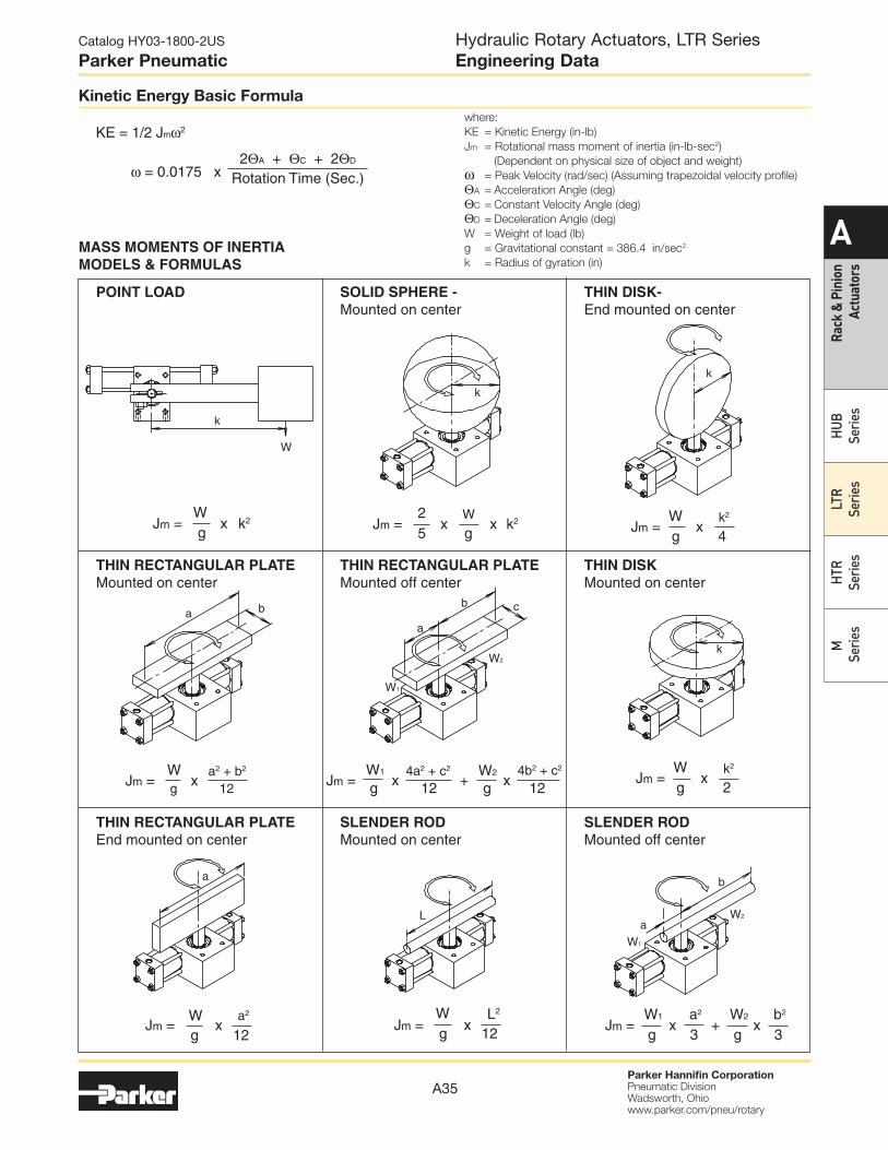
Standard Inch Unit with Face/Base Mount (A) and Male Keyed Shaft (B)
Standard Metric Unit with Face/Base Mount (B) and Male Keyed Shaft (D)
Double Male Keyed Shaft (C, F) shown in phantom
ST
V
M
A
A/2
M - Keyway Shown
Mid-Stroke Position
.030R
U - Port Size
(SAE O-ring)
F
F/2
J - Mtg. Holes
(4 Both Sides)
(4 Base)D
E
E/2
Ø P - Pinion
Journal
K N
O
L
B
B/2
H
H/2
C/2
C
R Sq.
0.01 (0.25mm)
Hydraulic Rotary Actuators, LTR Series
Dimensional Data
Dimensions for inch units (inches)
Model Rotation A B C D E F H J K L M N O P R S T U V
10
90°
180°
360°
6-11/16
8-1/4
1-17/16
2 3 2 1.50 2.00 1.501/4-20 x
3/8 DP
.500
.4997/8
.125
.127
.430
.4255/8 .59 1-1/2 .39 .31
7/16-20
SAE #43/4
15
90°
180°
360°
9-1/8
1-13/16
15-3/8
3 4-1/4 3 2.00 3.00 2.005/16-18
x 1/2 DP
.875
.8741-7/8
.188
.190
.771
.7611-1/2 .98 2 .44 .44
7/16-20
SAE #41-1/16
20
90°
180°
360°
11-3/16
14-1/16
19-11/16
3 5 4 2.50 3.50 2.003/8-16 x
1/2 DP
1.125
1.1241-7/8
.250
.252
.986
.9761-1/2 1.18 2-1/2 .50 .44
9/16-18
SAE #61-1/4
25
90°
180°
360°
12-9/16
15-1/2
20-5/8
3-1/2 6 4 2.50 4.50 2.001/2-13 x
3/4 DP
1.375
1.3742-1/4
.313
.315
1.201
1.1911-3/4 1.38 3 .50 .44
9/16-18
SAE #61-1/2
32
90°
180°
360°
16-5/8
21-1/8
29-3/8
5 8 5 3.00 5.00 2.503/4-10 x
1 DP
1.750
1.7493-1/2
.375
.377
1.542
1.5323 1.77 3-3/4 .58 .56
3/4-16
SAE #81-15/16
Dimensions for metric units (mm)
Model A B C D E F H J K L M P9 N O P R S T U* V
10
90°
180°
360°
169.9
209.6
290.5
50.8 76.2 50.8 40 50 40M6 x 1 x
10 DP
12.00
11.9822.2 4
10.9
10.815 15 38.1 9.9 7.9 1/8 19.1
15
90°
180°
360°
231.8
284.2
390.5
76.2 108.0 76.2 50 80 50
M8 x
1.25 x
13 DP
22.00
21.9847.6 6
18.5
18.438 25 50.8 11.1 11.2 1/4 27.0
20
90°
180°
360°
284.2
357.2
500.1
76.2 127.0 101.6 63 90 50
M10 x
1.5 x 13
DP
28.00
27.9847.6 8
24.0
23.838 30 63.5 12.7 11.2 1/4 31.8
25
90°
180°
360°
319.1
393.7
523.9
88.9 152.4 101.6 63 115 50
M12 x
1.75 x
19 DP
34.00
33.9857.2 10
29.0
28.844 35 76.2 12.7 11.2 1/4 38.1
32
90°
180°
360°
422.3
536.6
746.1
127.0 203.2 127.0 80 125 63
M20 x
2.5 x 25
DP
42.00
41.9888.9 12
37.0
36.876 45 95.3 14.8 14.2 1/2 49.2
* BSPP/G

A37
Catalog HY03-1800-2US
Parker Pneumatic
Parker Hannifin CorporationPneumatic DivisionWadsworth, Ohiowww.parker.com/pneu/rotary
A
Ra
ck
& P
inio
n
Actu
ato
rs
HU
B
Se
rie
s
LT
R
Se
rie
s
HT
R
Se
rie
s
M
Se
rie
s
Three Position Actuator (3)
In addition to the standard two position actuators, three
position units are also available. All standard options are
also available.
Operation:
A standard double rack unit is fitted with stop tubes of
varying lengths on the upper rack. Pressurizing port C-2
(with ports C-1, C-3 exhausted) causes counterclockwise
pinion rotation to angular position A. Alternately applying
pressure to C-1 (with C-2 and C-4 exhausted) will cause
clockwise rotation to angular position C. Both positions
A and C are at end of stroke, thus typical end cap options
such as cushions, bumpers, and stroke adjusters will
operate at these positions only.
Position B is obtained by pressurizing all ports.
Pressure applied to the upper floating pistons
centers the rack between the stop tubes, rotating
the pinion to position B. The lower rack is free
floating as the forces are equal on both ends.
Dimensional Data:
Three position actuator dimensions are identical to
the standard double rack units. If stroke adjusters
are specified they will be fitted to the upper rack,
flow controls and cushions will be on the lower rack.
Rotational tolerances are given in the chart to the
right.
Output Torque:
Output torque of the multiple position actuator is
equivalent to the torque output of the same size
single rack unit. The chart to the bottom right gives
selected torque values for specified pressures.
Ordering Information:
Three position actuators can be ordered by inserting a
3 into the “configuration” space in the model code.
The desired middle and total rotation should be stated
in the model code separated by a “/”. The beginning
position, 0°, need not be specified. For example:
LTR153-045/180-AB21-C is a standard, three position
actuator. Position A is 0°, position B is 45°, and
position C is 180°.
CAUTION: Keep loop pressure drops low for proper
operation.
Theoretical Output Torque, (in-lb) at Specified Pressure
Model
100 psi
(6.8 Bar)
500 psi
(34 Bar)
1000 psi
(68 Bar)
103 39 197 395
153 118 590 1180
203 282 1410 2820
253 430 2148 4295
323 1141 5703 11407
NOTE: When magnetic piston ring option “M” is ordered, all pistons will
be so equipped. The pressure rating is derated by 50% with the
magnetic piston option, due to aluminum cylinder tube being
used.
Rotation Tolerances
Model
Total Rotation,
Degrees
Between
Positions,
Degrees1
Backlash
Minutes
103 -0, +5 ±1 50
153 -0, +4 ±1/2 40
203 -0, +3 ±1/2 30
253 -0, +3 ±1/2 30
323 -0, +2 ±1/4 15
1. Measured from centers of backlash.
Stop TubeC3
C2 C1
C4
A
B
P T
POS. A
POS. B
POS. C
Hydraulic Rotary Actuators, LTR Series
Three Position Actuator (3)

A38
Catalog HY03-1800-2US
Parker Pneumatic
Parker Hannifin CorporationPneumatic DivisionWadsworth, Ohiowww.parker.com/pneu/rotary
A
Ra
ck
& P
inio
n
Actu
ato
rs
HU
B
Se
rie
s
LT
R
Se
rie
s
HT
R
Se
rie
s
M
Se
rie
s
Model Rotation
A B
inch mm inch mm
107
90 3-3/4 95 2-3/4 70
180 4-1/8 105 3-3/4 95
360 5-3/4 146 5 127
157
90 4-9/16 116 3-5/16 84
180 5-5/8 143 4-9/16 116
360 7-11/16 195 6-5/8 168
207
90 5-5/8 143 4-1/8 105
180 7-1/16 179 5-5/8 143
360 9-7/8 251 8-1/2 216
257
90 6-5/16 160 4-3/8 111
180 7-3/4 197 6-5/16 160
360 10-5/16 262 8-13/16 224
90 8-5/16 211 5-13/16 148
327 180 10-9/16 268 8-5/16 211
360 14-11/16 373 12-7/16 316
An antibacklash actuator is used to obtain precision
positioning at the end of rotation. The backlash
normally associated with rack and pinion actuators is
eliminated by this unique configuration.
Antibacklash Actuator (7)
Operation:
A double rack unit is modified for actuation on one end
only. Alternately pressurizing C-1 or C-2 causes clockwise
and counter-clockwise rotation, respectively. Backlash
in the rack & pinion is eliminated as the pinion is tightly
“trapped” between both racks at the end of stroke,
preventing any further motion.
Dimensional Data:
Antibacklash actuators are similar in size and configuration
to standard double rack units with one set of shorter
cylinders. The table to the right shows dimensions for
this shorter side. If cushions, stroke adjusters or port flow
controls are ordered, they will be fitted to the powered
rack side.
Output Torque:
Output torque of the antibacklash actuator is equivalent
to the torque output of the same size single rack unit.
The chart to the bottom right gives selected torque values
for specified pressures.
Ordering Information:
Antibacklash actuators can be ordered by inserting a
“7” into the “configuration” space in the model code.
For example: LTR157-180F-AR21-C is a hydraulic
antibacklash actuator with a theoretical output torque of
1000 in-lb at 1000 psi.
The optional stroke adjusters make the rotation variable
between 120° and 180°. The preload key option on the
shaft is also specified to eliminate any backlash in the key
and flange coupling interface.
C-1
C-2
A B
Theoretical output torque, (in-lb) at specified pressure
Model
100 psi
(6.8 bar)
500 psi
(34 bar)
1000 psi
(68 bar)
107 39 197 395
157 118 590 1180
207 282 1410 2820
257 430 2148 4295
327 1141 5703 11407
Hydraulic Rotary Actuators, LTR Series
Antibacklash Actuator (7)

A39
Catalog HY03-1800-2US
Parker Pneumatic
Parker Hannifin CorporationPneumatic DivisionWadsworth, Ohiowww.parker.com/pneu/rotary
A
Ra
ck
& P
inio
n
Actu
ato
rs
HU
B
Se
rie
s
LT
R
Se
rie
s
HT
R
Se
rie
s
M
Se
rie
s
Port Location (1, 2, 3, 4, 5)
NOTE:
1. Port position 1 is standard.
2. Port positions 2, 3 and 4 are standard options
available at no additional cost.
3. Port position 4 available with single rack actuators only.
4. For port position 5, consult factory.
Model
Standard SAE
Straight Thread (1)
NPT
(2)
BSPP/G
(4)
Metric
DIN (5) & ISO (6)
10 7/16 - 20 (SAE 4) 1/8 1/8 M10 x 1
15 7/16 - 20 (SAE 4) 1/4 1/4 M14 x 1.5
20 9/16 - 18 (SAE 6) 1/4 1/4 M14 x 1.5
25 9/16 - 18 (SAE 6) 1/4 1/4 M14 x 1.5
32 3/4 - 16 (SAE 8) 3/8 1/2 M22 x 1.5
Raised Ringwith Spot Face
ISO 6149/1 Port Identification
Port Threads (1, 2, 4, 5, 6)
Hydraulic Rotary Actuators, LTR Series
Options
End caps can be assembled to the units with ports
facing different directions as shown.
2
31
1 3
2
4
1
1
4
2
3
3
2
5
5
5
5

A40
Catalog HY03-1800-2US
Parker Pneumatic
Parker Hannifin CorporationPneumatic DivisionWadsworth, Ohiowww.parker.com/pneu/rotary
A
Ra
ck
& P
inio
n
Actu
ato
rs
HU
B
Se
rie
s
LT
R
Se
rie
s
HT
R
Se
rie
s
M
Se
rie
s
Floating Cushion Bushing
Cushion Adjustment Needle
(Shown in Position 3)
Typical Port in Position 2
Cushions (1, 2, 3, 4) *
The standard cushions operate over the
last 30° of rotation in either CW, CCW
or both directions. A floating bushing
ensures no binding of the cushion spear.
For severe operating conditions, four
cushions should be fitted on double rack
units. All cushions are fully adjustable.
On double rack units with type 1, 2 or
3, cushion adjustment will be located on
the upper cylinder.
* For gear train durability,
see table below.
High Performance Cushion (8)
(This option available with double rack units only)
By combining the output/exhaust flow from two cylinders,
then routing it across a single cushion needle, cushion
performance is improved. The increased volume passing
over the needle provides better control. This unique circuit
eliminates two pipe or tubing tees.
Operation:
The work ports of a standard directional valve are
plumbed to ports C-1 and C-2. Port A-1 is plumbed
directly to A-2, and port B-1 is plumbed to B-2. When
pressure is applied to port C-1 (clockwise shaft rotation),
fluid is also directed through line A to the other rack.
Exhaust flow from B-2 through B-1 is directed through
the cushion bushing and cushion adjustment at port C-2.
When the cushion spear closes off the main passage,
total flow from both end caps is directed across one
cushion adjustment needle, equalizing back pressure and
improving control. Alternatively, pressurizing C-2 and
exhausting C-1 reverses the operation.
Dimensional Information:
Units are identical to standard double rack and pinion
units, with the exception of porting location. This chart
describes the location of the ports.
Suggestion: Use Type 4 or Type 8 cushion arrangements
for double rack actuators. Use Type 1, 2 or 3 cushion
arrangements exclusively for single rack actuators.
Gear Set Durability
The table to the right provides energy ratings based on
gear train durability when using various cushion options
for the LTR Series.
Work ports
C-1, C-2
port position
Cushion
adjustment
position
Connection ports
A-1, A-2 & B-1, B-2
port position
1 2 3
2 3 1
3 2 1
Total energy capacity (in-lb) Port to port ∆P (PSID)
Model Code 1,2,3 Code 8 Code 1,2,3 Code 8
LTR101 141 N/A 800 N/A
LTR102 141 303 400 800
LTR151 348 N/A 650 N/A
LTR152 348 732 325 650
LTR201 936 N/A 750 N/A
LTR202 936 1982 375 750
LTR251 1098 N/A 550 N/A
LTR252 1098 2223 275 550
LTR321 2029 N/A 400 N/A
LTR322 2029 3222 200 400
A-2
C-1
B-2
B-1
C-2
A-1
Standard Cushion Adjuster
Needle Locations
Port
Position
Cushion Adjuster
Position
1 2
2 3
3 2
4** 3
5 Consult Factory
** On single rack only
Hydraulic Rotary Actuators, LTR Series
Options

A41
Catalog HY03-1800-2US
Parker Pneumatic
Parker Hannifin CorporationPneumatic DivisionWadsworth, Ohiowww.parker.com/pneu/rotary
A
Ra
ck
& P
inio
n
Actu
ato
rs
HU
B
Se
rie
s
LT
R
Se
rie
s
HT
R
Se
rie
s
M
Se
rie
s
Stroke Adjusters (D, E, F) 30°
Fine control of the end of travel points of the rotary
actuator can be obtained by specifying stroke
adjusters. These operate by reducing the maximum
travel of the actuator by up to 30° in each rotational
direction. Adjustment within this range is made
by the user. Several types of stroke adjuster are
available. The design illustrated is suitable for
applications requiring infrequent adjustment.
Stroke Adjusters and Cushions
The addition of stroke adjusters requires
an increase in build length. On double
rack units with cushions, the cushion
is fitted to the upper rack and the
stroke adjuster to the lower.
(Consult factory.)
The increase in build length, for both
single and double rack units, is
shown as dimension A in the table.
Cushion performance may be
affected by the addition of a
stroke adjuster. Please consult
the factory in critical applications.
Built in meter-out flow controls provide adjustment
of actuator speed and eliminate the cost and space
needed for externally plumbed components. A
separate ball check is used to provide free flow in the
opposite direction. Flow controls may be ordered in
conjunction with cushions or stroke adjusters.
Four port flow controls are suggested with double
rack actuators to avoid pinion gear damage.
Port Flow Controls (P, R, S)
Model
One (1)
turn adj.
A (max) – Increased build length
B
C
UNF
30°adjustment
without cushioned
end cap
10°adjustment*
with cushioned
end cap
inch mm inch mm
10 4.0° .63 16 .38 10 1/8 1/4-28
15 4.2° .88 23 1.13 29 1/4 1/2-20
20 3.1° 1.13 29 1.13 29 1/4 1/2-20
25 3.3° 1.13 29 1.13 29 1/4 1/2-20
32 2.6° 1.50 38 2.13 54 3/8 3/4-16
CAUTION: Due to end of stroke loading on some applications,
four stroke adjusters may be needed with double rack actuators
to avoid pinion gear damage.
* Standard cushions operate over the last 30° of standard rotation. Stroke
adjuster will decrease the effective cushion length by the amount of inward
adjustment.
Schematic
Hydraulic Rotary Actuators, LTR Series
Options
Standard Adjustment
Needle Locations
Port
Position
Needle
Position
1 2
2 3
3 2
4* 3
* On single rack onlyNOTE: When both cushions and port flow controls are specified the end
caps will be stamped “C” and “P” respectively near the adjustment
needles.
A
C - Thread Size
B - Hollow Hex
Thread Seal
Flow Adjustment Needle
Check Valve
A42
Catalog HY03-1800-2US
Parker Pneumatic
Parker Hannifin CorporationPneumatic DivisionWadsworth, Ohiowww.parker.com/pneu/rotary
A
Ra
ck
& P
inio
n
Actu
ato
rs
HU
B
Se
rie
s
LT
R
Se
rie
s
HT
R
Se
rie
s
M
Se
rie
s
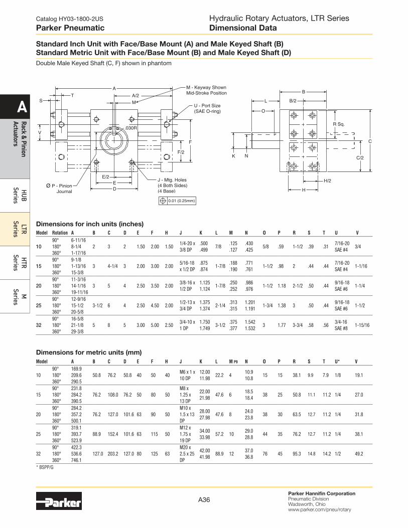
Mounting Options:
Inch Units (F, G, P, R)
Metric Units (H, K, S, T)
Pilot Ring (P, S)
Model
Inch (P) Metric (S)
G H G H
10 1.125 .125 28.58 3.2
15 2.001 .25 50.83 6.4
20 2.166 .23 55.04 5.8
25 2.680 .25 68.05 6.1
32 3.347 .25 85.04 6.4
Front (F, H) or Rear Flange (R, T)NOTE: Shaft seal cover option “S” is not available with flange mounting.
Model
Inch (F, R) Metric (H, T)
J K L M N P Q J K L M N P Q
10 4.25 2.00 3.625 1.375 .250 .281 .625 108 51 92 35 7 6.5 15
15 5.75 3.00 5.125 2.125 .438 .406 1.000 146 76 130 54 11 11 25
20 6.50 4.00 5.875 3.375 .438 .406 1.250 165 102 149 86 11 11 31
25 8.25 4.00 7.250 3.000 .438 .531 1.625 210 102 184 76 11 13.5 40
32 12.00 5.00 10.000 3.000 .750 .781 2.000 305 127 254 76 19 22 48
Flanged and Pilot Mountings
LTR Series rotary actuators are available with options such
as face/base, pilot or flanged mounting styles to suit the
requirements of different applications.
Note: Actuators are shipped with mounting flange installed unless
otherwise noted.
Foot Flange (G, K)
Model
Inch (G) Metric (K)
A B C D E F A B C D E F
10 3.25 2.00 2.625 1.375 .250 .281 82 51 67 35 7 6.5
15 4.50 3.00 3.875 2.125 .438 .406 114 76 98 54 11 11
20 4.50 4.00 3.875 3.375 .438 .406 114 102 98 86 11 11
25 5.50 4.00 4.500 3.000 .438 .531 140 102 114 76 11 13.5
32 8.00 5.00 6.500 3.500 .750 .781 N/A N/A N/A N/A N/A N/A
Hydraulic Rotary Actuators, LTR Series
Options
BD
Ø F Holes
A
C
E
Ø G
Pilot Ring
Pilot Ring
+.002
- .000
H
J N
Ø Q
Holes
Ø P
Holes
L
KM
A43
Catalog HY03-1800-2US
Parker Pneumatic
Parker Hannifin CorporationPneumatic DivisionWadsworth, Ohiowww.parker.com/pneu/rotary
A
Ra
ck
& P
inio
n
Actu
ato
rs
HU
B
Se
rie
s
LT
R
Se
rie
s
HT
R
Se
rie
s
M
Se
rie
s
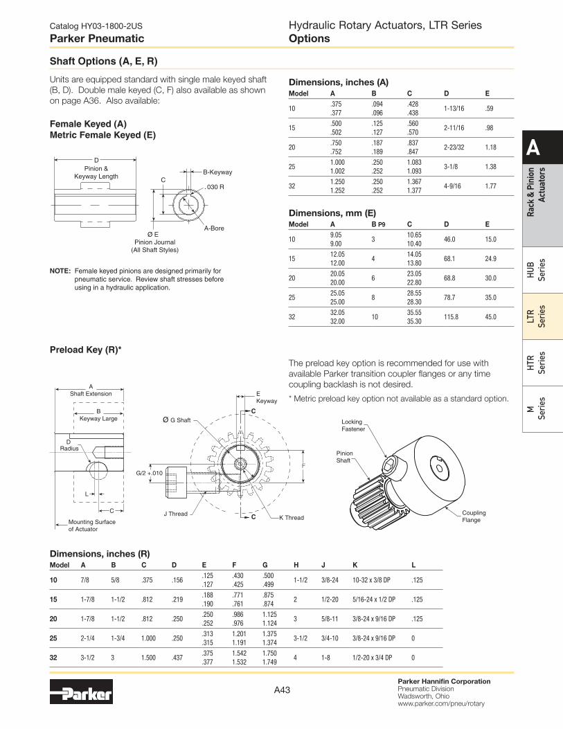
Female Keyed (A)
Metric Female Keyed (E)
NOTE: Female keyed pinions are designed primarily for
pneumatic service. Review shaft stresses before
using in a hydraulic application.
Units are equipped standard with single male keyed shaft
(B, D). Double male keyed (C, F) also available as shown
on page A36. Also available:
Dimensions, inches (A)Model A B C D E
10.375
.377
.094
.096
.428
.4381-13/16 .59
15.500
.502
.125
.127
.560
.5702-11/16 .98
20.750
.752
.187
.189
.837
.8472-23/32 1.18
251.000
1.002
.250
.252
1.083
1.0933-1/8 1.38
321.250
1.252
.250
.252
1.367
1.3774-9/16 1.77
Dimensions, mm (E)Model A B P9 C D E
109.05
9.003
10.65
10.4046.0 15.0
1512.05
12.004
14.05
13.8068.1 24.9
2020.05
20.006
23.05
22.8068.8 30.0
2525.05
25.008
28.55
28.3078.7 35.0
3232.05
32.0010
35.55
35.30115.8 45.0
Preload Key (R)*
Dimensions, inches (R)Model A B C D E F G H J K L
10 7/8 5/8 .375 .156.125
.127
.430
.425
.500
.4991-1/2 3/8-24 10-32 x 3/8 DP .125
15 1-7/8 1-1/2 .812 .219.188
.190
.771
.761
.875
.8742 1/2-20 5/16-24 x 1/2 DP .125
20 1-7/8 1-1/2 .812 .250.250
.252
.986
.976
1.125
1.1243 5/8-11 3/8-24 x 9/16 DP .125
25 2-1/4 1-3/4 1.000 .250.313
.315
1.201
1.191
1.375
1.3743-1/2 3/4-10 3/8-24 x 9/16 DP 0
32 3-1/2 3 1.500 .437.375
.377
1.542
1.532
1.750
1.7494 1-8 1/2-20 x 3/4 DP 0
The preload key option is recommended for use with
available Parker transition coupler flanges or any time
coupling backlash is not desired.
* Metric preload key option not available as a standard option.
Hydraulic Rotary Actuators, LTR Series
Options
Shaft Options (A, E, R)
B-Keyway
D
Pinion &
Keyway LengthC
Ø E
Pinion Journal
(All Shaft Styles)
030 R
A-Bore
C
C
C
L
D Radius
B
Keyway Large
Mounting Surface
of Actuator
G/2 +.010
E
Keyway
F
Ø G Shaft
K ThreadJ Thread
A
Shaft Extension
Coupling
Flange
Pinion
Shaft
Locking
Fastener

A44
Catalog HY03-1800-2US
Parker Pneumatic
Parker Hannifin CorporationPneumatic DivisionWadsworth, Ohiowww.parker.com/pneu/rotary
A
Ra
ck
& P
inio
n
Actu
ato
rs
HU
B
Se
rie
s
LT
R
Se
rie
s
HT
R
Se
rie
s
M
Se
rie
s
Shaft Seal covers are designed to prolong bearing life by
isolating them from external contamination and pressure.
They are designed for use with standard male shafts
only (not hollow shafts). Shaft seals are not available with
flange mounting.
Specifications
Max. Pressure Differential: 500 psi (34 bar)
Material: Anodized Aluminum
Shaft Seal: Double Lip Wiper
Body Seal: O-Ring
Shaft Seal Covers (S)
Magnetic Piston (M)
This option prepares the actuator for use with Reed and
Hall Effect switches. The “M” option should be specified
to provide a magnet on the cylinder piston and aluminum
cylinder tubes. The pressure of the actuator is derated by
50% with the magnetic piston option due to the aluminum
cylinder tubes.
Order switches separately from the Sensors section.
Model
A
inch (mm)
B
inch (mm)
10 .84 (21) 1.22 (30)
15 .99 (25) 1.46 (37)
20 1.27 (32) 1.68 (43)
25 1.45 (37) 1.89 (48)
32 1.71 (43) 2.20 (56)
Model
A B C D
Inch mm Inch mmInch (+.000, -.002)
mm (+.00, -.05) Inch mm
10 7/8 22 1/2 12 1.875 48 .25 7
15 1-7/8 46 1-5/16 33 3.000 76 .38 10
20 1-7/8 46 1/5/16 33 3.250 83 .38 10
25 2-1/4 56 1-5/8 41 3.625 92 .38 10
32 3-1/2 88 2-7/8 73 4.480 114 .38 10
Hydraulic Rotary Actuators, LTR Series
Options
1.00 (25.4)
1/16
Int. Hex
A
B
B
A
Ø C
(Typ)
D

A45
Catalog HY03-1800-2US
Parker Pneumatic
Parker Hannifin CorporationPneumatic DivisionWadsworth, Ohiowww.parker.com/pneu/rotary
A
Ra
ck
& P
inio
n
Actu
ato
rs
HU
B
Se
rie
s
LT
R
Se
rie
s
HT
R
Se
rie
s
M
Se
rie
s
Piston Seals (V, W)
Seal Options
Seal option code Seal type Wear ring type Fluid medium Temperature range Hydraulic filtration
Omit (Standard) Molythane Filled PTFE General purpose applications,
petroleum-based fluids
-40°F to 180°F
(-40°C to 82°C)
ISO Class 17/14
Cleanliness Level Option V Fluorocarbon Filled PTFE High temperature operation,
special synthetic fluids
-20°F to 250°F
(-29°C to 121°C)
Option W Carboxylated
Nitrile
Filled PTFE Water-based fluids 30°F to 180°F
(0°C to 82°C)
Feedback Packages
Hydraulic Rotary Actuators, LTR Series
Options
The floating Wear-Pak piston fitted as standard to all LTR
Series rotary actuator employes a filled PTFE wear band to
prevent metal-to-metal contact. The hydraulic LTR Series
actuator uses a Molythane Polypak seal, which is self-
energizing for improved sealing. The Molythane seal is
wear, roll and extrusion resistant. For higher temperatures
or use with synthetic fluids, Fluorocarbon seals should
be specified; for water glycol or high water content fluids,
carboxylated nitrile seals are available.
Filtration
Effective filtration is vital to the long life and satisfactory
performance of a rotary actuator. If the piston seals of a
rack and pinion rotary actuator are worn or damaged, fluid
leaks past the piston and will enter the gear housing.
Any external leakage from the gear housing indicates
worn or damaged piston seals. Seals and tubes should
be examined and, if necessary, be replaced at the earliest
opportunity.
Poly-Pak
Piston SealMagnet Groove
for Optional Switches
PTFE Wear Bands
Feedback packages available for use with LTR Series
rotary actuators include:
•Precisionfeedbackpotentiometer(J)•Precisionresolverfeedback(H)The feedback packages may be ordered as part of the
model code. See Sensors section for specifications.
Seal Kit Ordering Information
• Standard units are equipped with nitrile seals.
• Optional seal compounds are available.
• See parts list for items contained in seal kits.
PSK — LTR322 V
Parker Seal Kit Base Model Omit Nitrile Seals (Std)
V Fluorocarbon Seals
Q Quad Ring Piston Seals
W Carboxylated Nitrile (Piston Seals Only)

A46
Catalog HY03-1800-2US
Parker Pneumatic
Parker Hannifin CorporationPneumatic DivisionWadsworth, Ohiowww.parker.com/pneu/rotary
A
Ra
ck
& P
inio
n
Actu
ato
rs
HU
B
Se
rie
s
LT
R
Se
rie
s
HT
R
Se
rie
s
M
Se
rie
s
Proximity Switches
The inductive type proximity switch provides end of rotation indication.
The non-contact probe senses the presence of the ferrous cushion spear
and has no springs, plungers, cams or dynamic seals that can wear out
or go out of adjustment. The switch is solid state and meets NEMA 4, 12
& 13 specifications. For ease of wiring, the connector housing is rotatable
through 360°. To rotate, lift the cover latch, position, and release.
The switch make/break activation point may occur at 0.125" to ±0.125"
from end of stroke. Depending on the actuator size, this distance may
cause activation at 2° to 15° before end of stroke.
A standard proximity switch controls 50-230 VAC/DC loads from 5 to
500 mA. The low 1.7 mA off-state leakage current can allow use for
direct PLC input. The standard short circuit protection (SCP) protects
the switch from a short in the load or line upon sensing such a condition
(5 amp or greater current) by assuming a non-conductive mode. The fault
condition must be corrected and the power removed to reset the switch
preventing automatic restarts.
The low voltage DC switch is also available for use with 10-30 VDC.
This switch is in a non-rotatable housing, but does incorporate the
short circuit protection.
Both switches are equipped with two LEDs, “Ready” and “Target”. The
“Ready” LED is lit when power is applied and the cushion spear is not
present. The “Target” LED will light and the “Ready” LED will go out when
the switch is closed, indicating the presence of the cushion spear. Both
LEDs flashing indicates a short circuit condition.
NOTES:
1. Available with or without cushions.
2. Not available with stroke adjusters.
3. Prsesure rating: 3000 psi
4. Operating temperature: -4°F to 158°F
5. Specify switch type, orientation and voltage when ordering
6. Not available on size 10 units.
7. The low voltage DC switch is available in non-rotatable style only.
Consult representative for further information.
Switch Characteristics
Proximity Switches
• End Cap Mounted
• Solid State Electronics
• LED Indicator
• 10-30 VDC or 50-230 VAC/DC
• PNP and NPN Available
• Senses Cushion Spear on Piston
• Highest Cost
• Long Life
Hall Effect Switches
• Fully Adjustable Travel
• Solid State Electronics
• LED Indicator
• 50-30 VDC
• PNP and NPN Available
• Senses magnet band on piston
(Aluminum cylinders required)
• Medium Cost
• Long Life
Reed Switches
• Fully Adjustable Travel
• Mechanical Reed
• LED Indicator
• 50-30 VDC or 85-150 VAC
• Senses magnet band on piston
(Aluminum cylinders required)
• Lowest Cost
• Medium Life
Model
A, inch (mm)
EPS 5 EPS 6&7
15 1.88 (48) 2.17 (55.1)
20 2.44 (62) 2.75 (69.9)
25 2.16 (55) 2.48 (63.0)
32 1.94 (49) 2.25 (57.2)
Hall Effect and Reed Switches
Reed and Hall Effect switches are available for use with LTR Series rotary
actuators. The “M” option should be specified to provide a magnet on the
cylinder piston and to use aluminum cylinders.
Order proximity, Hall Effect
and reed switches separately.
See Sensors section for
specifications and ordering
information.
Hydraulic Rotary Actuators, LTR Series
Switches
1.55(39)
A
0.48(12)
1.38(35)