Embed Size (px)
Citation preview

“Made with pride in the USA”
CatalogCCT-08AShort Version
Effective Date:February 1, 2008
Supercedes: CCT-07AMarch 1, 2007
Courtesy of Steven Engineering, Inc.-230 Ryan Way, South San Francisco, CA 94080-6370-Main Office: (650) 588-9200-Outside Local Area: (800) 258-9200-www.stevenengineering.com

MICRON INDUSTRIES CATALOG CCT-08A REPLACES CCT-07A
Table of Contents
THE MICRON EDGE 3 - Warranty
Transformer Selection Process 4-5
Standards 6-UL/CSA-CUL-IEC
Control TransformersSeries 2 ImperviTRAN & ImperviTRAN 8-13-Connection Diagrams 14-Accessories 15-17
Overcurrent Protection Tables 18-19
GlobalTRAN 20-25-Connection Diagrams 26
Medium Voltage 27
Power SuppliesDINergy Power Supplies 28ImperviPOWER 67 29
LVGP -Overview 30
2
Courtesy of Steven Engineering, Inc.-230 Ryan Way, South San Francisco, CA 94080-6370-Main Office: (650) 588-9200-Outside Local Area: (800) 258-9200-www.stevenengineering.com

THE MICRON EDGEWhile other manufacturers
treat transformers asjust one of a variety of
products, transformers are THE major product
focus for Micron
This focus and resultingcommitment to excellence,
exemplified in ourunprecedented 20-yearwarranty¹, has made
Micron
#1with specifiers of
transformersfor over 30 years.
¹ 20 years applies to all 600 volt class Control Transformer product. LVGP and Medium Voltage are waranted for one year, Power Supplies for five.
3
Courtesy of Steven Engineering, Inc.-230 Ryan Way, South San Francisco, CA 94080-6370-Main Office: (650) 588-9200-Outside Local Area: (800) 258-9200-www.stevenengineering.com

TRANSFORMER SELECTION PROCESS Determining Inrush and Voltage Requirements Selecting a transformer for industrial control circuit applications requires knowledge of the following terms: INRUSH VA is the product of the load voltage (V) multiplied by the current (A) that is required during start-up. It is calculated by adding the inrush VA requirements of all devices (contactors, timers, relays, pilot lights, solenoids, etc.), which will be energized together. Inrush VA requirements are best obtained from the component manufacturer. SEALED VA also called Steady State VA, is the product of the load voltage (V) multiplied by the current (A) that is required to operate the circuit after initial start-up or under normal operating conditions. It is calculated by adding the sealed VA requirements of all electrical components of the circuit that will be energized at any given time. Sealed VA requirements are best obtained from the component manufacturer. PRIMARY VOLTAGE is the voltage available from the electrical distribution system and its operational frequency, which is connected to the transformer supply voltage (H) terminals. SECONDARY VOLTAGE is the voltage required for load operation, which is connected to the transformer load voltage (X) terminals. Once the circuit variables have been determined, transformer selection is a simple 5-step process as follows:
1. Determine the Application Inrush VA by using the following industry accepted formula.
Application Inrush VA = √ (INRUSH VA)² + (SEALED VA)²
2. Refer to the Regulation Data Chart. If the primary voltage is basically stable and does not vary by more than 5% from nominal, the 90% secondary voltage column should be used. If the primary voltage varies between 5 and 10%, the 95% secondary voltage column should be used.
3. After determining the proper secondary
voltage column, read down until a value equal to or greater than the Application Inrush VA is found. In no case should a lesser figure be used.
4. Read left to the Transformer VA Rating
column to determine the proper transformer for the application. As a final check, make sure that the Transformer VA Rating is equal to or greater than the total sealed VA requirements.
5. Refer to the catalog pages to determine
the proper catalog number based on the transformer VA and primary and secondary voltage requirements.
4
Courtesy of Steven Engineering, Inc.-230 Ryan Way, South San Francisco, CA 94080-6370-Main Office: (650) 588-9200-Outside Local Area: (800) 258-9200-www.stevenengineering.com

Catalog# CCT-08A Effective: 02/08
REGULATION DATA CHART
Transformer Inrush VA at 20% Power factorVA Rating NEMA / IEC NEMA / IEC NEMA / IEC To comply with NEMA standards, which require
95% Sec. 90% Sec. 85% Sec. all magnetic devices to operate successfully at 85%Voltage Voltage Voltage of rated voltage, the 90% secondary column is
25¹ 100 / ---- 130 / --- 150 / --- most often used in selecting a transformer. No50¹ 170 / 190 200 / 220 240 / 270 comparable requirement is available for IEC.75¹ 310 / 350 410 / 460 540 / 600100¹ 370 / 410 540 / 600 730 / 810150² 780 / 850 930 / 1030 1150 / 1270200² 810 / 900 1150 / 1270 1450 / 1600250² 1400 / 1540 1900 / 2090 2300 / 2530300² 1900 / 2090 2700 / 2970 3850 / 4240350² 3100 / 3410 3650 / 4020 4800 / 5280500² 4000 / 4400 5300 / 5830 7000 / 7700750² 8300 / 9130 11000 / 12100 14000 / 154001000² 15000 / 16500 21000 / 23000 27000 / 295001000³ 9000 / 9900 13000 / 14300 18500 / 203001500³ 10500 / 11500 15000 / 16500 20500 / 225002000³ 17000 / 18900 25500 / 27300 34000 / 364003000³ 24000 / 25700 36000 / 38500 47500 / 502005000³ 55000 / 58800 92500 / 98900 115000 / 122000
¹ For units with class 105° C insulation system.² For units with class 130° C insulation system.³ For units with class 180° C insulation system
5
Courtesy of Steven Engineering, Inc.-230 Ryan Way, South San Francisco, CA 94080-6370-Main Office: (650) 588-9200-Outside Local Area: (800) 258-9200-www.stevenengineering.com

INDUSTRY AND INTERNATIONAL STANDARDS
Micron offers a broad line of standard transformers, each made with the finest materials and workmanship. Laminations of high-grade silicon steel assure optimum performance and the finest quality copper magnet wire assures efficient operation. Insulation materials are of the highest rating available for the temperature class and mounting brackets of heavy gauge steel add strength and stability. All are UL 506 listed (File # E46323) and either C-UL or CSA certified (File # LR27533) and meet NEMA and ANSI requirements.
In response to the change in compliance standards for CE marking of industrial control transformers as required by IEC/EN guidelines, Micron has introduced new GlobalTRAN models in compliance with EN61558-2. This new IEC/EN standard replaces the previous IEC/EN 60742 standard for control power transformers that expired on December 31, 2003. The Micron design engineering department has produced 61558-2 compliant designs that permit the customer to retain mounting layouts used for the previous Micron 60742 designs.
GlobalTRAN® products carry the CE mark, certifying 100% compliance with requirements of EN61558 for Non-Short Circuit Proof Isolating Transformers. GlobalTRAN control transformers feature touch-proof terminals, utilizing either Micron's SafeTouch terminal covers or a touch-proof terminal block, and meet true IP-20 or IP-00 terminal protection ratings as defined by IEC-529.
Of course, all GlobalTRAN products also carry the UL listing and CSA certification. GlobalTRAN is the most reliable and versatile control transformer in the industry today. DINergy™ products are designed to meet the most stringent international specifications for safety and EMI; and are designed to compact dimensions. All carry C-UL certification to UL60950 and UL508 plus the CE mark signifying certification to EN60950, EN 55022B, EN 61000-3-2 and IEC610004-2, 3, 4, 5, 6, 8, 11. ImperviPOWER 67™ products are designed to meet the most stringent international specifications; and are designed to compact dimensions. All carry certification to UL60950, CSA 22.2, EN60950, EN 55011, EN 6100-6, EN6000-6-2, -4-2, -4-3, -4-4, -4-5, -4-6 and -4-11. UPC Standards: Micron’s base UPC identifier is 784550. Since the individual product identifiers may change with revision levels, contact Micron for the current identifier.
6
Courtesy of Steven Engineering, Inc.-230 Ryan Way, South San Francisco, CA 94080-6370-Main Office: (650) 588-9200-Outside Local Area: (800) 258-9200-www.stevenengineering.com
IMPERVITRAN
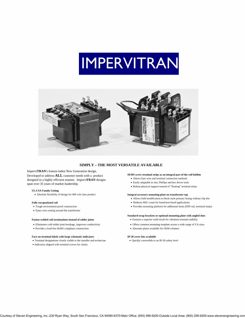
SIMPLY – THE MOST VERSATILE AVAILABLE
SEMS screw terminal strips as an integral part of the coil bobbin • Allows bare wire and terminal connection methods • Easily adaptable to slot, Phillips and hex driver tools • Robust physical support instead of “floating” terminal strips
UL/CSA Family Listing • Absolute flexibility of design for 600 volt class product Integral accessory mounting plate on transformer top
• Allows field modification to block-style primary fusing without clip kitsFully encapsulated coil • Reduces SKU count for fused/non-fused applications
• Tough environment-proof construction • Provides mounting platform for additional items (DIN rail, terminal strips) • Eases wire routing around the transformer
Standard strap brackets or optional mounting plate with angled slotsFusion-welded coil terminations instead of solder joints • Features a superior weld result for vibration-resistant stability
• Eliminates cold solder joint breakage, improves conductivity • Offers common mounting template across a wide range of VA sizes • Provides a lead-free RoHS compliant construction • Alternate plates available for OEM volumes
Face-on terminal labels with large schematic indicators IP-20 cover kits available • Terminal designations clearly visible to the installer and technician • Quickly convertible to an IP-20 safety level • Indicators aligned with terminal screws for clarity
ImperviTRAN's feature-laden New Generation design. Developed to address ALL customer needs with a product designed in a highly efficient manner. ImperviTRAN designs span over 35 years of market leadership.
Courtesy of Steven Engineering, Inc.-230 Ryan Way, South San Francisco, CA 94080-6370-Main Office: (650) 588-9200-Outside Local Area: (800) 258-9200-www.stevenengineering.com

Catalog CCT-08A Effective: 02/08
CONTROL TRANSFORMERSGENERAL SPECIFICATIONS: STYLE: SERIES 2 IMPERVITRAN STYLE: IMPERVITRANAPPROVALS: UL/Cul FILE# E46323 APPROVALS: UL LISTED FILE# E46323/ CSA APPROVED FILE# LR27533TEMP CLASS: 105°C/130°C TEMP CLASS: 105°C/130°C/180°CVA SIZES: 50-1500 VA SIZES: 1000-5000SUFFIX DESCRIPTION:"R" IN SUFFIX DENOTES INSTALLED CLASS "CC" PRIMARY FUSE BLOCKTWO LETTER SUFFIX = TEMP CLASS 105CTHREE LETTER SUFFIX ENDING "F" = TEMP CLASS 130CTHREE LETTER SUFFIX ENDING "H" = TEMP CLASS 180C
CATALOG CATALOG CATALOGNUMBER NUMBER NUMBER
GROUP "A" GROUP "C" GROUP "F" VOLTAGE: VOLTAGE: VOLTAGE:
PRI: 220x440, 230x460, 240x480 PRI: 120x240 PRI: 208/277SEC: 110/115/120 SEC: 24 SEC: 120
VA AMPS VA AMPS VA AMPSB050BTZ13JK 50 0.43 B050LP7JK 50 2.08 B050MQ15XK 50 0.42B050BTZ13RB B050LP7RB B050MQ15RK B075BTZ13JK 75 0.65 B075LP7JK 75 3.13 B075MQ15XK 75 0.63B075BTZ13RB B075LP7RB B075MQ15RKB100BTZ13JK 100 0.87 B100LP7JK 100 4.17 B100MQ15XK 100 0.83B100BTZ13RB B100LP7RB B100MQ15RKB150BTZ13JKF 150 1.30 B150LP7JKF 150 6.25 B150MQ15XKF 150 1.25B150BTZ13RBF B150LP7RBF B150MQ15RKFB200BTZ13JKF 200 1.74 B200LP7JKF 200 8.33 B200MQ15XKF 200 1.67B200BTZ13RBF B200LP7RBF B200MQ15RKFB250BTZ13JKF 250 2.17 B250LP7JKF 250 10.42 B250MQ15XKF 250 2.08B250BTZ13RBF B250LP7RBF B250MQ15RKFB300BTZ13JKF 300 2.61 B300LP7JKF 300 12.50 B300MQ15XKF 300 2.50B300BTZ13RBF B300LP7RBF B300MQ15RKFB350BTZ13JKF 350 3.04 B350LP7JKF 350 14.58 B350MQ15XKF 350 2.92B350BTZ13RBF B350LP7RBF B350MQ15RKFB500BTZ13JKF 500 4.35 B500LP7JKF 500 20.83 B500MQ15XKF 500 4.17B500BTZ13RBF B500LP7RBF B500MQ15RKFB750BTZ13JKF 750 6.52 B750LP7JXF 750 31.25 B750MQ15XKF 750 6.25B750BTZ13RBF B750LP7RCF B750MQ15RKFB1K0BTZ13JKF 1000 8.70 B1K0BTZ13RBF GROUP "G"B1K5BTZ13JKH 1500 13.04 VOLTAGE:B1K5BTZ13RBH PRI: 208/230/460B2K0BTZ13JKH 2000 17.39 SEC: 115B2K0BTZ13RBH B050MBT13XK 50 0.43B3K0BTZ13JXH 3000 26.09 B050MBT13RK B5K0BTZ13JXH 5000 43.48 B075MBT13XK 75 0.65
B075MBT13RK GROUP "B" GROUP "E" B100MBT13XK 100 0.87
VOLTAGE: VOLTAGE: B100MBT13RKPRI: 240x480 PRI: 550/575/600 B150MBT13XKF 150 1.30
SEC: 24 SEC: 110/115/120 B150MBT13RKFB050PU7JK 50 2.08 B050WZ13XK 50 0.43 B200MBT13XKF 200 1.74B050PU7RB B050WZ13RK B200MBT13RKFB075PU7JK 75 3.13 B075WZ13XK 75 0.65 B250MBT13XKF 250 2.17B075PU7RB B075WZ13RK B250MBT13RKFB100PU7JK 100 4.17 B100WZ13XK 100 0.87 B300MBT13XKF 300 2.61B100PU7RB B100WZ13RK B300MBT13RKFB150PU7JKF 150 6.25 B150WZ13XKF 150 1.30 B350MBT13XKF 350 3.04B150PU7RBF B150WZ13RKF B350MBT13RKFB200PU7JKF 200 8.33 B200WZ13XKF 200 1.74 B500MBT13XKF 500 4.35B200PU7RBF B200WZ13RKF B500MBT13RKFB250PU7JKF 250 10.42 B250WZ13XKF 250 2.17 B750MBT13XKF 750 6.52B250PU7RBF B250WZ13RKF B750MBT13RKFB300PU7JKF 300 12.50 B300WZ13XKF 300 2.61 B1K0MBT13XKF 1000 8.70B300PU7RBF B300WZ13RKF B1K0MBT13RKF B350PU7JKF 350 14.58 B350WZ13XKF 350 3.04 B1K5MBT13XKH 1500 13.04B350PU7RBF B350WZ13RKF B1K5MBT13RKH B500PU7JKF 500 20.83 B500WZ13XKF 500 4.35 B2K0MBT13XKH 2000 17.39B500PU7RBF B500WZ13RKF B2K0MBT13RKHB750PU7JXF 750 31.25 B750WZ13XKF 750 6.52 B3K0MBT13XXH 3000 26.09B750PU7RCF B750WZ13RKF B5K0MBT13XXH 5000 43.48
8
Courtesy of Steven Engineering, Inc.-230 Ryan Way, South San Francisco, CA 94080-6370-Main Office: (650) 588-9200-Outside Local Area: (800) 258-9200-www.stevenengineering.com

Catalog CCT-08A Effective: 02/08
CONTROL TRANSFORMERSSTYLE: SERIES 2 IMPERVITRAN STYLE: IMPERVITRAN
CATALOG CATALOG CATALOGNUMBER NUMBER NUMBER
GROUP "H" GROUP "J" GROUP "K"VOLTAGE: VOLTAGE: VOLTAGE:
PRI: 230/460/575 PRI: 208/230/460 PRI: 240x480SEC: 95/115 SEC: 24/115 SEC: 120x240
VA AMPS VA AMPS VA AMPSB050BTW37XX 50 0.53/0.44 B050-2000-1 50 2.08/0.44 B050PU1519JJ 50 0.42/0.21B050BTW37RX B050-2000-8 B050PU1519RR B075BTW37XX 75 0.79/0.65 B075-2001-1 75 3.13/0.65 B075PU1519JJ 75 0.63/0.31B075BTW37RX B075-2001-8 B075PU1519RRB100BTW37XX 100 1.05/0.87 B100-2002-1 100 4.17/0.87 B100PU1519JJ 100 0.83/0.42B100BTW37RX B100-2002-8 B100PU1519RR
B150BTW37XXF 150 1.58/1.30 B150-2003-1F 150 6.25/1.30 B150PU1519JJF 150 1.25/0.63B150BTW37RXF B150-2003-8F B150PU1519RRFB200BTW37XXF 200 2.11/1.74 B200-2004-1F 200 8.33/1.74 B200PU1519JJF 200 1.67/0.83B200BTW37RXF B200-2004-8F B200PU1519RRFB250BTW37XXF 250 2.63/2.17 B250-2005-1F 250 10.42/2.17 B250PU1519JJF 250 2.08/1.04B250BTW37RXF B250-2005-8F B250PU1519RRFB300BTW37XXF 300 3.16/2.61 B300-2006-1F 300 12.50/2.61 B300PU1519JJF 300 2.50/1.25B300BTW37RXF B300-2006-8F B300PU1519RRFB350BTW37XXF 350 3.68/3.04 B350-2007-1F 350 14.58/3.04 B350PU1519JJF 350 2.92/1.46B350BTW37RXF B350-2007-8F B350PU1519RRFB500BTW37XXF 500 5.26/4.35 B500-2008-1F 500 20.84/4.35 B500PU1519JJF 500 4.17/2.08B500BTW37RXF B500-2008-8F B500PU1519RRFB750BTW37XXF 750 7.89/6.52 B750-2009-1F 750 31.3/6.5 B750PU1519JJF 750 6.25/3.12B750BTW37RXF B750-2009-8F B750PU1519RRF
B1K0BTWZ37XKH 1000 10.53/8/70 B1K0-2010-1F 1000 41.7/8.7B1K0BTWZ37RKH B1K0-2010-8FB1K5BTWZ37XKH 1500 15.79/13.04B1K5BTWZ37RKH B2K0BTWZ37XKH 2000 21.05/17.39B2K0BTWZ37RKH B3K0BTWZ37XXH 3000 31.58/26.09B5K0BTWZ37XXH 5000 52.63/43.48
GROUP "I" GROUP "J"VOLTAGE: VOLTAGE:
PRI: 380/400/415 PRI: 208/230/460SEC: 110x220 SEC: 24/115
VA AMPS VA AMPSB050RFD34XJ 50 0.46/0.23 B050MBT713XK 50 2.08/0.44B050RFD34RJ B050MBT713RK B075RFD34XJ 75 0.68/0.34 B075MBT713XK 75 3.13/0.65B075RFD34RJ B075MBT713RKB100RFD34XJ 100 0.91/0.46 B100MBT713XK 100 4.17/0.87B100RFD34RJ B100MBT713RK
B150RFD34XJF 150 1.37/0.69 B150MBT713XKF 150 6.25/1.30B150RFD34RJF B150MBT713RKFB200RFD34XJF 200 1.82/0.91 B200MBT713XKF 200 8.33/1.74B200RFD34RJF B200MBT713RKFB250RFD34XJF 250 2.28/1.14 B250MBT713XKF 250 10.42/2.17B250RFD34RJF B250MBT713RKFB300RFD34XJF 300 2.72/1.36 B300MBT713XKF 300 12.50/2.61B300RFD34RJF B300MBT713RKFB350RFD34XJF 350 3.18/1.59 B350MBT713XKF 350 14.58/3.04B350RFD34RJF B350MBT713RKFB500RFD34XJF 500 4.55/2.27 B500MBT713XKF 500 20.84/4.35B500RFD34RJF B500MBT713RKFB750RFD34XJF 750 6.82/3.41B750RFD34RJF
9
Courtesy of Steven Engineering, Inc.-230 Ryan Way, South San Francisco, CA 94080-6370-Main Office: (650) 588-9200-Outside Local Area: (800) 258-9200-www.stevenengineering.com
Catalog CCT-08A Effective: 02/08
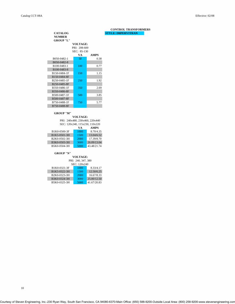
CONTROL TRANSFORMERS CATALOG STYLE: IMPERVITRAN
NUMBER GROUP "L"
VOLTAGE:PRI: 208-600SEC: 85-130
VA AMPSB050-0482-1 50 0.38B050-0482-8 B100-0483-1 100 0.77B100-0483-8
B150-0484-1F 150 1.15B150-0484-8FB250-0485-1F 250 1.92B250-0485-8FB350-0486-1F 350 2.69 B350-0486-8FB500-0487-1F 500 3.85B500-0487-8FB750-0488-1F 750 5.77B750-0488-8F
GROUP "M"VOLTAGE:
PRI: 240x480, 230x460, 220x440SEC: 120x240, 115x230, 110x220
VA AMPSB1K0-0500-3F 1000 8.70/4.35B1K5-0501-3H 1500 13.04/6.52B2K0-0502-3H 2000 17.39/8.70B3K0-0503-3H 3000 26.09/13.04B5K0-0504-3H 5000 43.48/21.74
GROUP "N"VOLTAGE:
PRI: 240, 347, 380SEC: 120x240
B1K0-0321-3F 1000 8.33/4.17B1K5-0322-3H 1500 12.50/6.25B2K0-0323-3H 2000 16.67/8.33B3K0-0324-3H 3000 25.00/12.50B5K0-0325-3H 5000 41.67/20.83
10
Courtesy of Steven Engineering, Inc.-230 Ryan Way, South San Francisco, CA 94080-6370-Main Office: (650) 588-9200-Outside Local Area: (800) 258-9200-www.stevenengineering.com

Catalog: CCT-08A Effective: 02/08
DIMENSIONAL DATA
NOTES: SERIES 2TRANSFORMERS 500VA AND LARGER ARE FITTED WITH 6-TERMINAL CONNECTION BLOCKS.
PRIMARY FUSE BLOCK ADDS 1.375" (35MM) TO "C" DIMENSION.
NO SECONDARY FUSE CLIP DEDUCTS 0.50 (12.7MM) FROM "C" DIMENSION. A D C B E
(MATCHED DIMENSIONS)CATALOG GROUPS
A, B, C, E, F, G*, H*, I, KVOLTAGE GROUPS DIMENSIONS INCHES/MM
BTZ13, PU7, LP7, WZ13, MQ15, A B C D E APPROXMBT13, BTW37, RFD34, PU1519 SERIES 2 (MAX) ALL VERSIONS INCL. FUSE CLIP (MAX) ALL VERSIONS ALL VERSIONS WEIGHT
VA IN MM IN MM IN MM IN MM IN MM LBS50 3.78 96 3.00 76 3.14 79 1.96 50 2.50 64 3.0075 4.03 102 3.00 76 3.14 79 2.42 62 2.50 64 4.00
100 4.03 102 3.38 86 3.46 86 2.42 62 2.82 71 5.20150 4.03 102 3.75 95 3.77 96 2.82 71 3.13 79 6.00200 4.38 111 4.50 114 4.40 112 2.62 67 3.75 95 8.00250 4.38 111 4.50 114 4.40 112 2.82 71 3.75 95 10.00300 4.75 121 4.50 114 4.40 112 3.18 81 3.75 95 12.00350 4.75 121 4.50 114 4.40 112 3.75 95 3.75 95 14.00500 6.11 155 5.25 133 5.14 131 3.88 99 4.38 111 16.00750 7.61 193 5.25 133 5.14 131 5.38 137 4.38 111 28.00
* GROUP "G" MATCHES IN 75, 150 & 250VA. G50 3.78 96 3.00 76 3.14 79 2.21 56 2.50 64 3.50
100 4.00 102 3.38 86 3.46 86 2.62 67 2.82 71 5.70200 4.38 111 4.50 114 4.40 112 2.82 71 3.75 95 7.00300 4.75 121 4.50 114 4.40 112 3.75 95 3.75 95 11.00350 5.75 146 4.50 114 4.40 112 4.72 120 3.75 95 13.00500 6.11 155 5.25 133 5.14 131 4.38 111 4.38 111 15.00750 7.61 193 5.25 133 5.14 131 5.87 149 4.38 111 28.00
* GROUP "H" MATCHES IN 200, 250, 300 & 500VA H50 4.03 102 3.00 76 2.72 69 2.20 56 2.50 64 3.5075 4.53 115 3.00 76 2.72 69 2.62 67 2.50 64 4.50
100 4.03 102 3.75 95 3.36 85 2.82 71 3.13 79 6.00150 4.53 115 3.75 95 3.36 85 3.18 81 3.75 95 7.70350 5.00 127 4.50 114 3.97 101 3.75 95 3.75 95 16.50750 8.11 206 5.25 133 4.63 118 5.87 149 4.38 111 28.00
DIAGRAMS BELOW DEPICT INSTALLED PRIMARY FUSING OPTION.
DIAGRAMS DEPICT UNITS 500VA AND UP.
11
Courtesy of Steven Engineering, Inc.-230 Ryan Way, South San Francisco, CA 94080-6370-Main Office: (650) 588-9200-Outside Local Area: (800) 258-9200-www.stevenengineering.com

Catalog CCT-08A Effective: 02/08
DIMENSIONAL DATA (KVA SIZES)
KVA SIZES CAN EITHER BE SERIES 2 OR IMPERVITRAN DIAGRAMS DEPICT SERIES 2 DESIGN.
NOTES:TRANSFORMERS 500VA AND LARGER ARE FITTED WITH 6-TERMINAL CONNECTION BLOCKS.
PRIMARY FUSE BLOCK ADDS 1.375" (35MM) TO "C" DIMENSION.
NO SECONDARY FUSE CLIP DEDUCTS 0.50 (12.7MM) FROM "C" DIMENSION. A D C B E
DIMENSIONS INCHES/MM CATALOG (VOLTAGE) GROUP A B C D E APPROX
A (BTZ13) (MAX) INCL. FUSE CLIP (MAX) WEIGHTVA IN MM IN MM IN MM IN MM IN MM LBS
1000 6.11 155 6.75 172 6.30 160 3.91 99 6.13 156 30.501500 8.11 206 6.75 172 6.32 161 6.12 155 6.13 156 50.102000 7.75 197 6.75 172 6.28 160 4.97 126 6.13 156 46.003000 8.06 205 9.00 229 7.50 191 5.25 133 7.50 191 55.905000 10.38 264 9.00 229 7.50 191 7.56 192 7.50 191 84.40
G (MBT13)
1000 7.44 189 6.38 162 5.42 138 5.09 129 5.31 135 37.001500 8.50 216 6.75 172 5.73 146 6.09 155 6.13 156 53.902000 8.13 207 6.75 172 5.75 146 5.25 133 6.13 156 42.003000 8.56 217 9.00 229 7.50 191 5.75 146 7.50 191 64.505000 10.00 254 9.00 229 7.50 191 7.19 183 7.50 191 97.00
H (BTWZ37)
1000 7.00 178 6.38 162 5.42 138 5.06 129 5.31 135 31.801500 7.45 189 6.75 172 6.29 160 5.25 133 6.13 156 44.202000 7.56 192 9.00 229 7.80 198 4.81 122 7.50 191 57.703000 8.75 222 9.00 229 7.50 191 5.94 151 7.50 191 76.205000 11.00 279 9.00 229 7.50 191 8.19 208 7.50 191 127.40
M 240/480 X 120/240
1000 7.00 178 5.25 133 4.25 108 5.38 137 4.38 111 26.301500 7.00 178 6.75 172 5.75 146 4.25 108 6.13 156 31.002000 7.75 197 6.75 172 5.73 146 4.97 126 6.13 156 46.003000 8.06 205 9.00 229 7.50 191 5.25 133 7.50 191 56.005000 10.00 254 9.00 229 7.50 191 7.19 183 7.50 191 85.40
N240,347,380 X 120/240
1000 7.38 187 6.38 162 5.44 138 5.06 129 5.31 135 29.001500 8.13 207 6.38 162 5.44 138 5.06 129 5.31 135 33.302000 8.88 226 6.75 172 5.75 146 6.13 156 6.13 156 50.003000 8.50 216 9.00 229 7.50 191 5.69 146 7.50 191 74.005000 10.38 264 9.00 229 7.50 191 7.56 192 7.50 191 110.00
DIAGRAMS DEPICT IMPERVITRAN DESIGN.
12
Courtesy of Steven Engineering, Inc.-230 Ryan Way, South San Francisco, CA 94080-6370-Main Office: (650) 588-9200-Outside Local Area: (800) 258-9200-www.stevenengineering.com

Catalog CCT-08A Effective: 02/08
DIMENSIONAL DATA
NOTES: SERIES 2TRANSFORMERS 500VA AND LARGER ARE FITTED WITH 6-TERMINAL CONNECTION
BLOCKS.
PRIMARY FUSE BLOCK ADDS 1.375" (35MM) TO "C" DIMENSION.
NO SECONDARY FUSE CLIP DEDUCTS 0.50 (12.7MM) FROM "C" DIMENSION. A D C B E
DIMENSIONS INCHES/MM CATALOG (VOLTAGE) GROUP A B C D E APPROX
J SERIES 2 (MAX) ALL VERSIONS INCL. FUSE CLIP (MAX) ALL VERSIONS ALL VERSIONS WEIGHTP/N IN MM IN MM IN MM IN MM IN MM LBS
B050MBT713XK 3.50 89 3.00 76 3.14 79 2.25 57 2.50 64 3.40B075MBT713XK 3.50 89 3.38 86 3.44 87 2.44 62 2.82 71 4.80B100MBT713XK 3.63 92 3.75 95 3.78 96 2.44 62 3.13 79 5.90
B150MBT713XKF 4.00 102 3.75 95 3.78 96 3.19 81 3.13 79 8.00 B200MBT713XKF 4.38 111 4.50 114 4.40 112 3.00 76 3.75 95 9.80
B250MBT713XKF 4.38 111 4.50 114 4.40 112 3.75 95 3.75 95 12.00B300MBT713XKF 5.19 132 5.25 133 5.14 131 3.88 99 4.38 111 14.00B350MBT713XKF 5.00 127 5.25 133 5.14 131 3.88 99 4.38 111 15.00B500MBT713XKF 5.50 140 5.25 133 5.14 131 5.38 137 4.38 111 18.00 J
B050-2000-1 4.53 115 3.00 76 3.14 79 2.82 71 2.50 64 3.40B075-2001-1 4.53 115 3.75 95 3.78 96 2.82 71 3.13 79 4.80B100-2002-1 4.53 115 3.75 95 3.78 96 3.00 76 3.13 79 5.90
B150-2003-1F 5.03 128 3.75 95 3.78 96 3.19 81 3.13 79 8.00B200-2004-1F 4.38 111 4.50 114 4.40 112 3.00 76 3.75 95 9.80B250-2005-1F 4.75 121 4.50 114 4.40 112 3.75 95 3.75 95 12.00B300-2006-1F 6.11 155 5.25 133 5.14 131 3.88 99 4.38 111 14.00B350-2007-1F 6.11 155 5.25 133 5.14 131 3.88 99 4.38 111 15.00B500-2008-1F 7.11 181 5.25 133 5.14 131 5.38 137 4.38 111 18.00
L B050-0482-1 3.44 87 3.88 99 3.38 86 2.41 61 2.81 71 4.00B100-0483-1 4.00 102 3.75 95 3.50 89 3.00 76 3.13 79 6.60
B150-0484-1F 4.00 102 4.50 114 4.50 114 2.82 71 3.75 95 8.70B250-0485-1F 5.75 146 4.50 114 4.50 114 4.38 111 3.75 95 11.40B350-0486-1F 5.14 131 5.25 133 4.75 121 4.38 111 4.38 111 13.60B500-0487-1F 7.19 183 5.14 131 4.75 121 5.88 149 4.38 111 17.40B750-0488-1F 6.50 165 6.75 172 6.00 152 4.25 108 6.13 156 27.50
DIAGRAMS BELOW DEPICT INSTALLED PRIMARY FUSING OPTION.
DIAGRAMS DEPICT UNITS 500VA AND UP.
13
Courtesy of Steven Engineering, Inc.-230 Ryan Way, South San Francisco, CA 94080-6370-Main Office: (650) 588-9200-Outside Local Area: (800) 258-9200-www.stevenengineering.com
Catalog CCT-08A Effective: 02/08
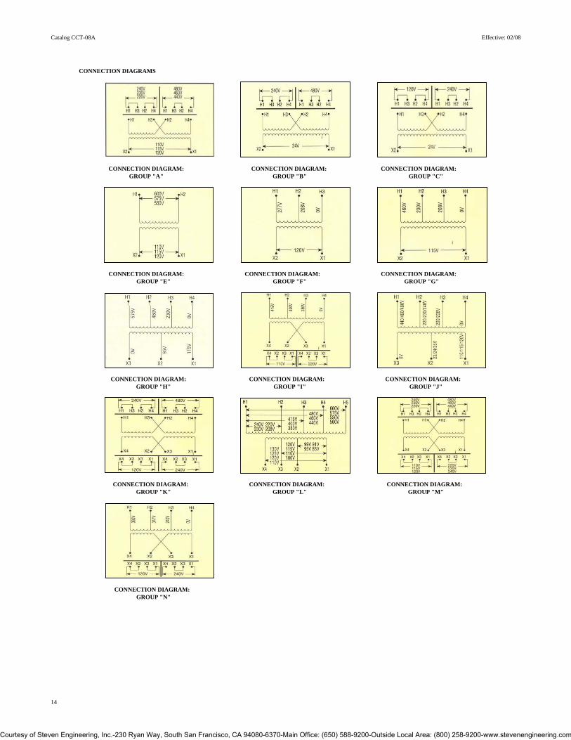
CONNECTION DIAGRAMS
CONNECTION DIAGRAM: CONNECTION DIAGRAM: CONNECTION DIAGRAM:GROUP "A" GROUP "B" GROUP "C"
CONNECTION DIAGRAM: CONNECTION DIAGRAM: CONNECTION DIAGRAM: GROUP "E" GROUP "F" GROUP "G"
CONNECTION DIAGRAM: CONNECTION DIAGRAM: CONNECTION DIAGRAM: GROUP "H" GROUP "I" GROUP "J"
CONNECTION DIAGRAM: CONNECTION DIAGRAM: CONNECTION DIAGRAM: GROUP "K" GROUP "L" GROUP "M"
CONNECTION DIAGRAM: GROUP "N"
14
Courtesy of Steven Engineering, Inc.-230 Ryan Way, South San Francisco, CA 94080-6370-Main Office: (650) 588-9200-Outside Local Area: (800) 258-9200-www.stevenengineering.com

Catalog CCT-08A Effective: 02/08
CONTROL TRANSFORMER ACCESSORIES CATALOG APPROX.
NUMBER WEIGHT LBS KG
IP-20 SAFETOUCH™ COVERSTPTC-2001 10PACK 4TERM. 1.0 0.5TPTC-2002 10PACK 6TERM. 1.0 0.5TPTC-2006 10PACK UNIVERSAL PRI BLOCK 1.0 0.5
FKTP-1001 PRIMARY CL "CC" FUSE KIT 0.25 0.1
OPTIONAL FACTORY INSTALLED FUSE HOLDERSCL. "CC" PRI. P/N SUFFIX = RB, RK, RX, RJ, RR N/A
RY, RG, RL, RN, RC, -8*NON-REJECTION VERSION AVAILABLEON ALL FACTORY INSTALLED PRIMARY FUSEBLOCK OPTIONS
1/4 X 1-1/4 SEC. P/N SUFFIX = JQ, XQ N/A9/16 X 2 SEC. P/N SUFFIX = JM, XM N/A
BULK FUSE CLIPS514-1661-01C (2 NECESSARY) 13/32 X 1-1/2 (STD) N/A514-1661-02C (2 NECESSARY) 1/4 X 1-1/4 (OPT) N/A
BULK JUMPERS514-1650 J-2 N/A514-1652 J-3 N/A
514-1620-02 Flat N/A
TRANSFORMER ACCESSORY INTERCHANGE MATRIX
DUAL PRIMARYSTANDARD SUFFIX FUSED SUFFIX
JK, JKF, JKH >> RB, RBF, RBHXK, XKF, XKH >> RK, RKF, RKHXX, XXF, XXH >> RX, RXF, RXHXJ, XJF, XJH >> RJ, RJF, RJHJJ, JJF, JJH >> RR, RRF, RRH
JM, JMF, JMH >> RY, RYF, RYHXM, JMF, JMH >> RG, RGF, RGHJQ, JQF, JQH >> RL RLF, RLH
XQ, XQF, XQH >> RN, RNF, RNHJX, JXF, JXH >> RC, RCF, RCH-1, -1F, -1H >> -8, -8F, -8H
15
Courtesy of Steven Engineering, Inc.-230 Ryan Way, South San Francisco, CA 94080-6370-Main Office: (650) 588-9200-Outside Local Area: (800) 258-9200-www.stevenengineering.com

Catalog CCT-08A Effective: 02/08
PRIMARY FUSE KIT # FKTP-1001 IP-20 COVER KIT # TPTC-2006SERIES 2 INSTRUCTIONS ON NEXT PAGE
4. Remove two nuts or screws holding primary fuse block to transformer. On FKTP-1001 kits, perform step #5 prior to affixing block to brackets.5. Install retaining clips in base of fuse block. Secure with nuts or screws as appropriate.
In addition to factory installed primary fusing capability 6, 6a. Install fuse in cover and snap cover in place. When installedMicron offers a primary fuse kit for ImperviTRAN and cover cannot be removed without releasing tab from detent (6a).ValuTRAN intended for field installation. The A tip of a pen will suffice.primary fuse kit includes a 2-pole Class "CC" fuse block, instructions and all associated mounting GLOBALTRAN ACCESSORIEShardware. Addititonally, this fuse block will fit mostcompetitive units. To order this kit, use catalog number A number of fusing accessories are available for the FKTP-1001. The primary fuse kit, when installed, will GlobalTRAN product line. Please contact Micron add a maximum of 11/16" to the transformer "A" with your design requirements.dimension and 1-15/16" to the "C" dimension.Installed as indicated.1. Loosen two outer screws on primary side of transformer. On 6 position shell leave 2 spaces open between brackets.2. Capture mounting brackets and necessary leads under terminal screws and tighten. Recommended torque 30 in-lbs.3. Affix fuse block to mounting bracket with supplied screws.
16
Courtesy of Steven Engineering, Inc.-230 Ryan Way, South San Francisco, CA 94080-6370-Main Office: (650) 588-9200-Outside Local Area: (800) 258-9200-www.stevenengineering.com

Catalog CCT-08A Effective: 02/08
PRIMARY FUSE KIT # FKTP-1001 SERIES 2 INSTRUCTIONS
In addition to factory installed primary fusing capabilityMicron offers a primary fuse kit for units with integral accessory mounting plate (#2) intended for field installation on all catalog standard SERIES 2 units.The primary fuse kit includes a 2-pole Class "CC" fuse block, instructions and all associated mounting hardware. To order this kit, use catalog number FKTP-1001. The primary fuse kit, when installed, willadd a maximum of 1-3/8" to the "C" dimension.(as measured from the top of the plate)
Installation instructions.1. Connect one end of the 2 primary leads (#1) under the appropriate primary terminal screws. Secure screws to 16 in-lbs <500VA and 30 in-lbs 500VA and larger.2. Insert locking clips (#4) oriented as shown into the fuse block (#3) pockets. Use caution in choosing screw length if locking clips are not used.3. Attach clips and fuse block to accessory mounting plate (#2) using screws (#5). Recommended torque 16 in-lbs.4. Insert fuses (not supplied) into fuse block followed by fuse fuse block covers (#6) (IF ORDERED) with lock slots (#6a) matching tip of the clips, as shown. Press down until cover locks. Refer to primary fuse chart for recommended fuses. Cover cannot be removed without releasing tab from detent (#6a). A tip of a pen will suffice.5. Connect trhe other end of the 2 primary leads (#1) under the screws on each of the 2 poles on the fuse block (#3a) and secure to 20 inch-pounds.6. Apply primary voltage to the opposite end of the fuse block (#3b).
Additionally the mounting plate (#2) can be utilized to mount other accessories such as DIN rail. Use caution in choosing screw length.
17
Courtesy of Steven Engineering, Inc.-230 Ryan Way, South San Francisco, CA 94080-6370-Main Office: (650) 588-9200-Outside Local Area: (800) 258-9200-www.stevenengineering.com

Catalog CCT-08A Effective: 02/08
UL OVERCURRENT PROTECTION - PRIMARY
Overcurrent protection on both the primary and secondary sides of transformers are specified in UL 508 and the National Electric Code.The maximum acceptable ratings are shown below. Due to the high inrush currents present when a transformer is intially energized, it is recommended that the primary fuses be time delay, to prevent nuisance trips during start-up
MAXIMUM ACCEPTABLE RATING OF PRIMARY OVERCURRENT PROTECTIONPrimary VA RatingVoltage 25 50 75 100 150 200 250 300 350 500 750
115 6/10 1-1/4 1-8/10 2-1/2 3-1/2 5 5 6-1/4 7-1/2 10 15(1) (2) (3-2/10) (4) (6-1/4) (8)
120 6/10 1-1/4 1-8/10 2-1/4 3-1/2 5 5 6-1/4 7 10 15(1) (2) (3) (4) (6-1/4) (8)
200 3/10 3/4 1-1/8 1-1/2 2-1/4 3 3-1/2 4-1/2 5 6-1/4 9(6/10) (1-1/4) (1-8/10) (2-1/2) (3-1/2) (5) (6-1/4) (7-1/2) (8)
208 3/10 6/10 1 1-4/10 2 2-8/10 3-1/2 4 5 6 9(6/10) (1-1/8) (1-8/10) (2-1/4) (3-1/2) (4-1/2) (6) (7) (8)
220 3/10 6/10 1 1-1/4 2 2-1/2 3-2/10 4 4-1/2 5-6/10 8(1/2) (1-1/8) (1-6/10) (2-1/4) (3-2/10) (4-1/2) (5-6/10) (6-1/4) (7-1/2)
230 3/10 6/10 8/10 1-1/4 1-8/10 2-1/2 3-2/10 3-1/2 4-1/2 5 8(1/2) (1) (1-6/10) (2) (3-2/10) (4) (5) (6-1/4) (7-1/2)
240 3/10 6/10 8/10 1-1/4 1-8/10 2-1/4 3 3-1/2 4 5 7-1/2(1/2) (1) (1-1/2) (2) (3) (4) (5) (6-1/4) (7)
277 1/4 1/2 8/10 1 1-6/10 2 2-1/2 3-2/10 3-1/2 5 6-1/4(4/10) (8/10) (1-1/4) (1-8/10) (2-1/2) (3-1/2) (4-1/2) (5) (6-1/4) (9)
380 3/16 3/10 1/2 3/4 1-1/8 1-1/2 1-8/10 2-1/4 2-1/2 3-1/2 5-6/10(3/10) (6/10) (8/10) (1-1/4) (1-8/10) (2-1/2) (3-2/10) (3-1/2) (4-1/2) (6-1/4) (9)
400 3/16 3/10 1/2 3/4 1-1/8 1-1/2 1-8/10 2-1/4 2-1/2 3-1/2 5-6/10(3/10) (6/10) (8/10) (1-1/4) (1-8/10) (2-1/2) (3) (3-1/2) (4) (6-1/4) (9)
415 15/100 3/10 1/2 6/10 1 1-4/10 1-8/10 2 2-1/2 3-1/2 5(3/10) (6/10) (8/10) (1-1/8) (1-8/10) (2-1/4) (3) (3-1/2) (4) (6) (9)
440 15/100 3/10 1/2 6/10 1 1-1/4 1-6/10 2 2-1/4 3-2/10 5(1/4) (1/2) (8/10) (1-1/8) (1-6/10) (2-1/4) (2-8/10) (3-2/10) (3-1/2) (5-6/10) (8)
460 15/100 3/10 4/10 6/10 8/10 1-1/4 1-6/10 1-8/10 2-1/4 3-2/10 4-1/2(1/4) (1/2) (8/10) (1) (1-6/10) (2) (2-1/2) (3-2/10) (3-1/2) (5) (8)
480 15/100 3/10 4/10 6/10 8/10 1-1/4 1-1/2 1-8/10 2 3 4-1/2(1/4) (1/2) (3/4) (1) (1-1/2) (2) (2-1/2) (3) (3-1/2) (5) (7-1/2)
550 1/8 1/4 4/10 1/2 8/10 1 1-1/4 1-6/10 1-8/10 2-1/2 4(2/10) (4/10) (6/10) (8/10) (1-1/4) (1-8/10) (2-1/4) (2-1/2) (3) (4-1/2) (6-1/4)
575 1/8 1/4 3/10 1/2 3/4 1 1-1/4 1-1/2 1-8/10 2-1/2 3-1/2(2/10) (4/10) (6/10) (8/10) (1-1/4) (1-6/10) (2) (2-1/2) (3) (4) (6-1/4)
600 1/8 2/10 3/10 1/2 3/4 8/10 1-1/4 1-1/2 1-6/10 2-1/4 3-1/2(2/10) (4/10) (6/10) (8/10) (1-1/4) 1-6/10) (2) (2-1/2) (2-8/10) (4) (6-1/4)
PRIMARY CURRENT = TRANSFORMER VA ÷ PRIMARY VOLTSIf the rated primary current is less than 2 amps, the maximum rating of the overcurrent device is 300% for power circuits, shown above, or 500% for control circuits, shown above in (brackets ). If the rated primary current is 2 amps or more, the maximum rating of the overcurrent device is 250%. All figures assume secondary overcurrent protection per UL/NEC.
18
Courtesy of Steven Engineering, Inc.-230 Ryan Way, South San Francisco, CA 94080-6370-Main Office: (650) 588-9200-Outside Local Area: (800) 258-9200-www.stevenengineering.com
Catalog CCT-08A Effective: 02/08
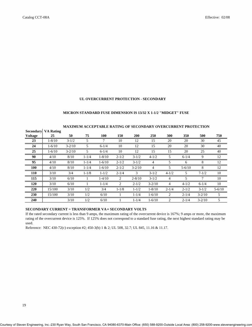
UL OVERCURRENT PROTECTION - SECONDARY
MICRON STANDARD FUSE DIMENSION IS 13/32 X 1-1/2 "MIDGET" FUSE
MAXIMUM ACCEPTABLE RATING OF SECONDARY OVERCURRENT PROTECTIONSecondary VA RatingVoltage 25 50 75 100 150 200 250 300 350 500 750
23 1-8/10 3-1/2 5 7 10 12 15 20 20 30 4524 1-6/10 3-2/10 5 6-1/4 10 12 15 20 20 30 4025 1-6/10 3-2/10 5 6-1/4 10 12 15 15 20 25 4090 4/10 8/10 1-1/4 1-8/10 2-1/2 3-1/2 4-1/2 5 6-1/4 9 1295 4/10 8/10 1-1/4 1-6/10 2-1/2 3-1/2 4 5 6 8 12
100 4/10 8/10 1-1/4 1-6/10 2-1/2 3-2/10 4 5 5-6/10 8 12110 3/10 3/4 1-1/8 1-1/2 2-1/4 3 3-1/2 4-1/2 5 7-1/2 10115 3/10 6/10 1 1-4/10 2 2-8/10 3-1/2 4 5 7 10120 3/10 6/10 1 1-1/4 2 2-1/2 3-2/10 4 4-1/2 6-1/4 10220 15/100 3/10 1/2 3/4 1-1/8 1-1/2 1-8/10 2-1/4 2-1/2 3-1/2 5-6/10230 15/100 3/10 1/2 6/10 1 1-1/4 1-6/10 2 2-1/4 3-2/10 5240 3/10 1/2 6/10 1 1-1/4 1-6/10 2 2-1/4 3-2/10 5
SECONDARY CURRENT = TRANSFORMER VA ÷ SECONDARY VOLTSIf the rated secondary current is less than 9 amps, the maximum rating of the overcurrent device is 167%; 9 amps or more, the maximumrating of the overcurrent device is 125%. If 125% does not correspond to a standard fuse rating, the next highest standard rating may be used.Reference: NEC 430-72(c) exception #2; 450-3(b) 1 & 2; UL 508, 32.7; UL 845, 11.16 & 11.17.
19
Courtesy of Steven Engineering, Inc.-230 Ryan Way, South San Francisco, CA 94080-6370-Main Office: (650) 588-9200-Outside Local Area: (800) 258-9200-www.stevenengineering.com

Features and Benefits
Lead -free solder joints Encapsulated from 25Va through 5KVa • Provides RoHS compliant construction • Establishes product similarity throughout the product range
Fully encapsulated coil Full nameplate VA rating • Tough environment-proof construction • Eliminates guesswork • Eases wire routing around the transformer
Molded terminals as an integral part of the coil Largest standard voltage selection in the industry • Easily adaptable to slot and Phillips driver tools • Solves “availability problem” for many OEM design-in opportunities • Robust physical support instead of “floating” terminal strips • Both 4 and 6 terminals, or the combination, available
IP-20 level covers installed UL/CSA/CE Family Listing • Meets IEC-529 protection rating • Absolute flexibility of special design capability for 600 volt class product
GlobalTRAN products carry the CE mark, certifying 100% compliance with requirements of EN61558. Additionally all GlobalTRAN products are designed to deliver the full nameplate VA rating.
GLOBALTRAN
Courtesy of Steven Engineering, Inc.-230 Ryan Way, South San Francisco, CA 94080-6370-Main Office: (650) 588-9200-Outside Local Area: (800) 258-9200-www.stevenengineering.com

Catalog CCT-08A Effective: 02/08
CE CONTROL TRANSFORMERSGENERAL SPECIFICATIONS: STYLE: IMPERVITRANAPPROVALS: UL LISTED FILE# E46323/ CSA APPROVED FILE# LR27533, EN 61558-2-2TEMP CLASS: 105°C/130°C/180°CVA SIZES: 50-5000SUFFIX DESCRIPTION:TWO LETTER SUFFIX = TEMP CLASS 105CTHREE LETTER SUFFIX ENDING "F" = TEMP CLASS 130CTHREE LETTER SUFFIX ENDING "H" = TEMP CLASS 180C
GLOBALTRAN: GLOBALTRAN: GROUP "A" GROUP "D"
CATALOG CATALOGNUMBER NUMBER
VOLTAGE: VOLTAGE:PRI: 220x440, 230x460, 240x480 PRI: 550/575/600
SEC: 110/115/120 SEC: 110/115/120VA AMPS VA AMPS
B050-2001-GA 50 0.43 B050-2041-GA 50 0.43B075-2002-GA 75 0.65 B075-2042-GA 75 0.65B100-2003-GA 100 0.87 B100-2043-GA 100 0.87
B150-2004-GAF 150 1.30 B150-2044-GAF 150 1.30B200-2005-GAF 200 1.74 B200-2045-GAF 200 1.74B250-2006-GAF 250 2.17 B250-2046-GAF 250 2.17B300-2007-GAF 300 2.61 B300-2047-GAF 300 2.61B350-2008-GAF 350 3.04 B350-2048-GAF 350 3.04B500-2009-GAF 500 4.35 B500-2049-GAF 500 4.35B750-2010-GAF 750 6.52 B750-2050-GAF 750 6.52B1K0-2008-GAH 1000 8.70B1K5-2009-GAH 1500 13.04B2K0-2010-GAH 2000 17.39B3K0-2011-GAH 3000 26.09 B5K0-2012-GAH 5000 45.45
GROUP "B" GROUP "E"
VOLTAGE: VOLTAGE:PRI: 240x480 PRI: 380/400/415
SEC: 24 SEC: 110x220 VA AMPS VA AMPS
B050-2011-GA 50 2.08 B050-2061-GA 50 .46/.23 B075-2012-GA 75 3.13 B075-2062-GA 75 .68/.34 B100-2013-GA 100 4.17 B100-2063-GA 100 .91/.46
B150-2014-GAF 150 6.25 B150-2064-GAF 150 1.37/.69 B200-2015-GAF 200 8.33 B200-2065-GAF 200 1.82/.91 B250-2016-GAF 250 10.42 B250-2066-GAF 250 2.28/1.14 B300-2017-GAF 300 12.50 B300-2067-GAF 300 2.72/1.36 B350-2018-GAF 350 14.58 B350-2068-GAF 350 3.18/1.59 B500-2019-GAF 500 20.83 B500-2069-GAF 500 4.55/2.27B750-2020-GAF 750 31.25 B750-2070-GAF 750 6.82/3.41B1K0-2028-GAF 1000 41.67
GROUP "C" GROUP "F" VOLTAGE: VOLTAGE:
PRI: 120x240 PRI: 208/230/460SEC: 24 SEC: 24/115
VA AMPS VA AMPSB050-2021-GA 50 2.08 B050-2101-GA 50 2.08/.44 B075-2022-GA 75 3.13 B075-2102-GA 75 3.13/.65 B100-2023-GA 100 4.17 B100-2103-GA 100 4.17/.87
B150-2024-GAF 150 6.25 B150-2104-GAF 150 6.25/1.3 B200-2025-GAF 200 8.33 B200-2105-GAF 200 8.33/1.74 B250-2026-GAF 250 10.42 B250-2106-GAF 250 10.42/2.17 B300-2027-GAF 300 12.50 B300-2107-GAF 300 12.50/2.61 B350-2028-GAF 350 14.58 B350-2108-GAF 350 14.58/3.04 B500-2029-GAF 500 20.83 B500-2109-GAF 500 20.83/4.35 B750-2030-GAF 750 31.25 B750-2110-GAF 750 31.25/6.52 B1K0-2048-GAF 1000 41.67 B1K0-2188-GAH 1000 41.67/8.70
21
Courtesy of Steven Engineering, Inc.-230 Ryan Way, South San Francisco, CA 94080-6370-Main Office: (650) 588-9200-Outside Local Area: (800) 258-9200-www.stevenengineering.com

Catalog CCT-08A Effective 02/08
CE CONTROL TRANSFORMERS
GLOBALTRAN: GLOBALTRAN: GROUP "G" GROUP "I"
CATALOG CATALOG NUMBER NUMBER
VOLTAGE: VOLTAGE:PRI: 380 PRI: 208/230/400/460/575SEC: 24 SEC: 24*/115/230
VA AMPS VA AMPSB050-2051-GA 50 2.08 B250-2263-GAF 250 10.4/2.2/1.1 B075-2052-GA 75 3.13 B300-2264-GAF 300 12.5/2.6/1.3 B100-2053-GA 100 4.17 B350-2265-GAF 350 14.6/3.0/1.5 B150-2054-GAF 150 6.25 B500-2266-GAF 500 20.8/4.3/2.2 B200-2055-GAF 200 8.33 B750-2267-GAF 750 31.3/6.5/3.3 B250-2056-GAF 250 10.42 B1K0-2268-GAH 1000 41.7/8.7/4.3 B300-2057-GAF 300 12.50 B1K5-2269-GAH 1500 13.04/6.52 B350-2058-GAF 350 14.58 B2K0-2270-GAH 2000 17.39/8.70 B500-2059-GAF 500 20.83 B3K0-2271-GAH 3000 26.09/13.04 B750-2060-GAF 750 31.25 B5K0-2272-GAH 5000 43.48/21.74
* 24 AVAILABLE THROUGH 1Kva
GROUP "H" GROUP "J" VOLTAGE: VOLTAGE: PRI: 208-600 PRI: 230/400/460/575SEC: 85-130 SEC: 24/115
VA AMPS VA AMPSB250-2283-GAF 250 1.92 B250-2243-GAF 250 10.4/2.2B300-2284-GAF 300 2.31 B300-2244-GAF 300 12.5/2.6 B350-2285-GAF 350 2.69 B350-2245-GAF 350 14.6/3.0 B500-2286-GAF 500 3.85 B500-2246-GAF 500 20.8/4.3 B750-2287-GAF 750 5.77 B750-2247-GAF 750 31.3/6.5 B1K0-2288-GAH 1000 7.69 B1K0-2248-GAH 1000 41.7/8.7 B1K5-2289-GAH 1500 11.54 B2K0-2290-GAH 2000 15.38B3K0-2291-GAH 3000 23.08
22
Courtesy of Steven Engineering, Inc.-230 Ryan Way, South San Francisco, CA 94080-6370-Main Office: (650) 588-9200-Outside Local Area: (800) 258-9200-www.stevenengineering.com

Catalog CCT-08A Effective : 02/08
4 TERMINAL 6 TERMINAL
A D C B E
CATALOG GROUPS DIMENSIONS INCHES (MM) APPROXP/N A B C D E WEIGHTA IN MM IN MM IN MM IN MM IN MM LBS
B050-2001-GA 3.38 86 3.00 76 3.00 76 2.44 61 2.50 64 3.4B075-2002-GA 3.38 86 3.38 86 3.25 83 2.44 61 2.81 71 4.8B100-2003-GA 3.38 86 3.75 95 3.50 89 2.44 61 3.13 79 5.9
B150-2004-GAF 3.75 95 4.50 114 4.00 102 2.44 61 3.75 95 8.5B200-2005-GAF 3.75 95 4.50 114 4.00 102 2.81 71 3.75 95 10.0B250-2006-GAF 4.00 102 4.50 114 4.00 102 3.19 81 3.75 95 11.0B300-2007-GAF 4.38 111 4.50 114 4.00 102 3.75 95 3.75 95 13.0B350-2008-GAF 4.88 124 5.25 133 4.50 114 3.38 86 4.38 111 15.0B500-2009-GAF 5.13 130 5.25 133 4.50 114 4.38 111 4.38 111 20.0B750-2010-GAF 7.00 178 5.25 133 4.50 114 5.88 149 4.38 111 29.8B1K0-2008-GAH 6.63 168 6.38 162 5.50 140 3.75 95 5.31 135 35.0B1K5-2009-GAH 7.31 186 6.75 172 6.00 152 5.00 127 6.13 156 40.0B2K0-2010-GAH 8.13 203 6.75 172 6.00 152 5.25 133 6.13 156 45.0B3K0-2011-GAH 8.06 202 9.00 225 8.00 200 5.25 133 7.50 191 65.2B5K0-2012-GAH 10.00 250 9.00 225 8.00 200 7.19 183 7.50 191 104.8
B
B050-2011-GA 3.38 86 3.00 76 3.00 76 2.19 56 2.50 64 3.4B075-2012-GA 3.38 86 3.38 86 3.25 83 2.19 56 2.81 71 4.2B100-2013-GA 3.38 86 3.75 95 3.50 89 2.44 61 3.13 80 5.9
B150-2014-GAF 4.00 102 4.50 114 4.00 102 2.44 62 3.75 95 8.5B200-2015-GAF 3.75 95 4.50 114 4.00 102 2.81 71 3.75 95 10.0B250-2016-GAF 4.00 102 4.50 114 4.00 102 3.19 81 3.75 95 11.0B300-2017-GAF 4.38 111 4.50 114 4.00 102 3.75 95 3.75 95 13.2B350-2018-GAF 4.50 114 5.25 133 4.50 114 3.38 86 4.38 111 14.9B500-2019-GAF 5.13 130 5.25 133 4.50 114 3.88 99 4.38 111 19.2B750-2020-GAF 7.00 178 5.25 133 5.00 127 5.38 137 4.38 111 28.1B1K0-2028-GAF 7.00 178 6.38 162 6.00 152 3.75 95 5.31 135 30.0
CB050-2021-GA 3.38 86 3.00 76 3.00 76 2.19 55 2.50 64 3.4B075-2022-GA 3.38 86 3.38 86 3.25 83 2.19 56 2.81 71 4.2B100-2023-GA 3.38 86 3.75 95 3.50 89 2.44 61 3.13 79 5.9
B150-2024-GAF 3.75 95 4.50 114 4.00 102 2.44 61 3.75 95 8.5B200-2025-GAF 3.75 95 4.50 114 4.00 102 2.81 70 3.75 95 10.0B250-2026-GAF 4.00 102 4.50 114 4.00 102 3.19 81 3.75 95 11.0B300-2027-GAF 4.38 111 4.50 114 4.00 102 3.75 95 3.75 95 13.2B350-2028-GAF 4.50 114 5.25 133 4.50 114 3.38 86 4.38 111 14.9B500-2029-GAF 5.13 130 5.25 133 4.50 114 3.88 99 4.38 111 19.2B750-2030-GAF 7.00 178 5.25 133 4.50 114 5.88 149 4.38 111 29.8B1K0-2048-GAF 7.00 178 6.38 162 6.00 152 3.75 95 5.31 135 31.0
DB050-2041-GA 3.38 86 3.00 76 3.00 76 2.44 61 2.50 64 3.4B075-2042-GA 3.38 86 3.38 86 3.25 83 2.44 61 2.81 71 4.8B100-2043-GA 3.38 86 3.75 95 3.50 89 2.44 61 3.13 80 5.9
B150-2044-GAF 3.75 95 4.50 114 4.00 102 2.44 61 3.75 95 8.5B200-2045-GAF 3.75 95 4.50 114 4.00 102 3.00 76 3.75 95 10.0B250-2046-GAF 4.00 102 4.50 114 4.00 102 3.19 81 3.75 95 11.0B300-2047-GAF 4.38 111 4.50 114 4.00 102 3.75 95 3.75 95 13.0B350-2048-GAF 4.50 114 5.25 133 4.50 114 3.38 86 4.38 111 15.0B500-2049-GAF 5.13 130 5.25 133 4.50 114 4.38 111 4.38 111 20.0B750-2050-GAF 7.00 178 5.25 133 4.50 114 5.38 137 4.38 111 28.0
23
Courtesy of Steven Engineering, Inc.-230 Ryan Way, South San Francisco, CA 94080-6370-Main Office: (650) 588-9200-Outside Local Area: (800) 258-9200-www.stevenengineering.com

Catalog CCT-08A Effective 02/08
4 TERMINAL 6 TERMINAL
A D C B E
CATALOG GROUPS DIMENSIONS INCHES (MM) APPROXP/N A B C D E WEIGHTE IN MM IN MM IN MM IN MM IN MM LBS
B050-2061-GA 3.38 86 3.00 76 3.00 76 2.44 61 2.50 64 3.4B075-2062-GA 3.38 86 3.38 86 3.50 89 2.44 61 2.81 71 4.8B100-2063-GA 3.38 86 3.75 95 3.50 89 2.44 61 3.13 79 5.9
B150-2064-GAF 3.75 95 4.50 114 4.00 102 2.44 61 3.75 95 8.5B200-2065-GAF 3.75 95 4.50 114 4.00 102 3.00 76 3.75 95 10.0B250-2066-GAF 4.00 102 4.50 114 4.00 102 3.19 81 3.75 95 11.0B300-2067-GAF 4.38 111 4.50 114 4.00 102 3.75 95 3.75 95 13.0B350-2068-GAF 4.75 121 4.50 114 4.00 102 3.75 95 3.75 95 15.0B500-2069-GAF 5.13 130 5.25 133 4.50 114 4.38 111 4.38 111 20.0B750-2070-GAF 7.00 178 5.25 133 4.50 114 5.88 149 4.38 111 27.0
F
B050-2101-GA 3.38 86 3.00 76 3.25 83 2.25 56 2.81 71 4.2B075-2102-GA 3.38 86 3.38 86 3.50 89 2.44 61 3.13 79 5.9B100-2103-GA 3.63 92 3.75 95 3.50 89 3.19 81 3.13 79 7.9
B150-2104-GAF 3.75 95 4.50 114 4.00 102 2.81 71 3.75 95 10.0B200-2105-GAF 4.38 111 4.50 114 4.00 102 3.44 87 3.75 95 12.8B250-2106-GAF 4.75 121 4.50 114 4.00 102 3.75 95 3.75 95 14.0B300-2107-GAF 4.88 124 5.25 133 4.50 114 3.88 99 4.38 111 16.8B350-2108-GAF 4.88 124 5.25 133 4.50 114 3.88 99 4.38 111 19.2B500-2109-GAF 5.63 143 5.25 133 4.50 114 5.88 149 4.38 111 29B750-2110-GAF 6.63 168 6.38 162 6.00 152 5.06 129 5.31 111 29.8B1K0-2188-GAH 7.06 179 6.38 162 6.00 152 5.06 129 5.31 135 30.2
GB050-2051-GA 3.38 86 3.00 76 3.00 76 2.19 55 2.50 64 3.5B075-2052-GA 3.38 86 3.38 86 3.25 83 2.19 56 2.81 71 4.2B100-2053-GA 3.38 86 3.75 95 3.50 89 2.44 61 3.13 79 5.9B150-2054-GAF 3.63 91 3.75 95 3.50 89 3.00 61 3.13 79 7.3B200-2055-GAF 3.75 95 4.50 114 4.00 102 2.81 70 3.75 95 9.6B250-2056-GAF 4.00 102 4.50 114 4.00 102 3.19 81 3.75 95 11.3B300-2057-GAF 4.38 111 4.50 114 4.00 102 3.75 95 3.75 95 13.2B350-2058-GAF 4.50 114 5.25 133 4.50 114 3.88 99 4.38 111 14.9B500-2059-GAF 5.13 130 5.25 133 4.50 114 3.88 99 4.38 111 19.2B750-2060-GAF 7.00 178 5.25 133 4.50 114 5.88 149 4.38 111 29.8
HB250-2283-GAF 4.25 108 4.50 114 4.00 102 3.44 86 3.75 95 11.4B300-2284-GAF 4.75 121 4.50 114 4.00 102 3.75 95 3.75 95 13.6B350-2285-GAF 5.00 127 4.50 114 4.00 102 3.75 95 3.75 95 14.2B500-2286-GAF 5.50 140 5.25 133 4.25 108 3.88 99 4.38 111 17.4B750-2287-GAF 7.38 187 5.25 133 4.50 114 5.88 149 4.38 111 27.5B1K0-2288-GAH 7.00 178 6.38 162 5.50 140 5.06 129 5.31 135 27.9B1K5-2289-GAH 7.75 199 6.75 171 6.00 152 5.00 127 6.13 156 43.1B2K0-2290-GAH 7.63 194 9.00 229 8.00 203 4.81 122 7.50 191 56.0B3K0-2291-GAH 8.56 217 9.00 229 7.63 194 5.75 146 7.50 191 76.2
24
Courtesy of Steven Engineering, Inc.-230 Ryan Way, South San Francisco, CA 94080-6370-Main Office: (650) 588-9200-Outside Local Area: (800) 258-9200-www.stevenengineering.com

Catalog CCT-08A Effective: 02/08
4 TERMINAL 6 TERMINAL
A D C B E
CATALOG GROUPS DIMENSIONS INCHES (MM) APPROXP/N A B C D E WEIGHT
I IN MM IN MM IN MM IN MM IN MM LBSB250-2263-GAF 4.75 121 4.50 114 4.00 102 4.75 121 3.75 95 14.9B300-2264-GAF 5.25 133 4.50 114 4.00 102 4.75 121 3.75 95 17.4B350-2265-GAF 5.38 137 5.25 133 4.50 114 4.38 111 4.38 111 17.8B500-2266-GAF 5.63 168 5.25 133 4.50 114 5.88 149 4.38 111 26.6B750-2267-GAF 7.44 189 6.38 162 6.00 152 5.06 129 5.31 135 32.5B1K0-2268-GAH 7.75 199 6.75 171 6.25 159 5.00 127 6.13 156 44.0B1K5-2269-GAH 7.75 199 6.75 171 6.00 152 5.00 127 6.13 156 45.4B2K0-2270-GAH 7.63 194 9.00 229 7.63 194 4.81 122 7.50 191 58.6B3K0-2271-GAH 8.75 222 9.00 229 7.63 194 5.94 151 7.50 191 92.9B5K0-2272-GAH 10.44 265 9.00 229 7.63 194 7.63 194 7.50 191 127.4
J
B250-2243-GAF 4.75 121 4.50 114 4.00 102 3.75 95 3.75 95 14.3B300-2244-GAF 5.00 127 4.50 114 4.00 102 4.75 121 3.75 95 15.8B350-2245-GAF 5.13 130 5.25 133 4.50 114 3.88 99 4.38 111 16.5B500-2246-GAF 5.75 146 5.25 133 4.50 114 4.88 124 4.38 111 20.5B750-2247-GAF 7.00 178 6.38 162 6.00 152 5.06 129 5.31 135 28.8B1K0-2248-GAH 8.13 207 6.38 162 6.00 152 5.06 129 5.31 135 34.9
25
Courtesy of Steven Engineering, Inc.-230 Ryan Way, South San Francisco, CA 94080-6370-Main Office: (650) 588-9200-Outside Local Area: (800) 258-9200-www.stevenengineering.com

Catalog CCT-08A Effective: 02/08
CONNECTION DIAGRAMS - GLOBALTRAN
CONNECTION DIAGRAM: CONNECTION DIAGRAM: CONNECTION DIAGRAM: GROUP "A" GROUP "B" GROUP "C"
CONNECTION DIAGRAM: CONNECTION DIAGRAM: CONNECTION DIAGRAM: GROUP "D" GROUP "E" GROUP "F"
CONNECTION DIAGRAM: CONNECTION DIAGRAM: GROUP "G" GROUP "H"
CONNECTION DIAGRAM: CONNECTION DIAGRAM: CONNECTION DIAGRAM: GROUP "I" GROUP "I" GROUP "J"
Above 1 Kva Through 1 Kva
26
Courtesy of Steven Engineering, Inc.-230 Ryan Way, South San Francisco, CA 94080-6370-Main Office: (650) 588-9200-Outside Local Area: (800) 258-9200-www.stevenengineering.com

Catalog CCT-08A Effective: 02/08
MEDIUM VOLTAGE CONTROL TRANSFORMERS
Micron medium voltage control transformers have:
* 130° C Insulation system. * 24" Mimimum primary lead length.* 60Hz.
* HIPOT - 7,400 volts for 2400 primary.* HIPOT - 11,500 volts for 4160 and 2400 primaries.* 750 VA - Epoxy impregnated coils.* 1 KVA and larger - Epoxy potted primary coils.
DIMENSIONS
CONTROL TRANSFORMERS: MEDIUM VOLTAGE CATALOG OUTPUT DIMENSIONS INCHES (MM) APPROX.
NUMBER VA AMPS A B C D E WEIGHTVOLTAGE: IN MM IN MM IN MM IN MM IN MM LBS
*PRI: 4200 PRI: 2400SEC: 120
H750-0030 * 750 6.25 6.63 168 6.38 162 5.81 148 5.25 133 5.31 135 30.5H750-0031 750 6.25 6.63 168 6.38 162 5.81 148 5.25 133 5.31 135 30.7
*PRI: 4160 PRI: 2400
SEC: 120/240H1K0-0010 1000 8.33/4.17 6.25 159 7.56 192 6.38 162 3.50 89 5.63 143 31.3H1K0-0015 * 1000 8.33/4.17 6.25 159 7.56 192 6.38 162 3.50 89 5.63 143 31.1
HN1K5F1519P 1500 12.50/6.25 7.00 178 9.00 229 7.63 194 4.25 108 6.50 165 53.7HN1K5G1519P * 1500 12.50/6.25 7.00 178 9.00 229 7.63 194 4.25 108 6.50 165 52.2HN2K0F1519P 2000 16.67/8.33 7.94 202 9.00 229 7.63 194 5.19 132 6.50 165 65.4HN2K0G1519P * 2000 16.67/8.33 7.94 202 9.00 229 7.63 194 5.19 132 6.50 165 58.2HN3K0F1519P 3000 25.00/12.50 9.75 248 9.00 229 7.63 194 7.00 178 6.50 165 99.9HN3K0G1519P * 3000 25.00/12.50 9.75 248 9.00 229 7.63 194 7.00 178 6.50 165 101.0
27
Courtesy of Steven Engineering, Inc.-230 Ryan Way, South San Francisco, CA 94080-6370-Main Office: (650) 588-9200-Outside Local Area: (800) 258-9200-www.stevenengineering.com

Micron DINergy™ MDP SERIES Plastic Case DIN Rail Power Supplies
·Low cost industrial power solution · Attractive small form plastic case
·Wide range input voltage · DC-OK visual indicator LED
·Adjustable output voltage · Over voltage protection
·Over load and short circuit protection · EN61000-3-2 compliant
·EMI compliant with EN55022,FCC15 ·UL508,UL60950 and CE certification
Courtesy of Steven Engineering, Inc.-230 Ryan Way, South San Francisco, CA 94080-6370-Main Office: (650) 588-9200-Outside Local Area: (800) 258-9200-www.stevenengineering.com

Model Output voltage Adjust range Output current Total power
MDP15-24-1 24 V 22-28 V 0.68 - 0.54 A
MDP15-12-1 12 V 10-14 V 1.50 - 1.07 A 15W
MDP30-24-1 24 V 22-28 V 1.25 A
MDP30-15-1 15 V 14-18 V 2 A
MDP30-12-1 12 V 10-14 V 2.5 A
30W
MDP30-5-1 5 V 4.5-5.5 V 4 A 20W
MDP50-48-1 48 V 46-52 V 1.09 - 0.96 A
MDP50-24-1 24 V 22-28 V 2.27 - 1.79 A
MDP50-12-1 12 V 10-14 V 5.00 - 3.57 A
50W
Note: Products are rated for industrial environments and are not to be used nor are warranted in aerospace, medical or lifesafety
applications.
GENERAL SPECIFICATIONS
Input voltage 100-240 VAC, +6%、-10% Connector Size 12-22 AWG
Input Frequency 47-63 HZ
Power Factor TBD Connector Types:
Standard Screw Terminations
Harmonic Emissions Conforms to EN61000-3-2 Installation Clearance requirements
25mm above and below; 15mm in front .
Hold-Up time 16 ms
DC Input Voltage 240-300VDC,+-15%
Inrush Current < 25A@120vac, cold start
Operating Temperature
-10 to 45 Degrees ℃,
Full Power; to 60
Degrees ℃ with
derating'.
Input Current 0.8A max.
Mounting Direction Vertical Efficiency
Up to 85% at 230VAC
(15W:75% at 230VAC) Visual Indication
1 Green LED for DC OK
Overload Condition Above 105%~150% Hiccup mode Over voltage
Protection Auto-restart limited to 105-150%.
Internal Fuse Yes Short Circuit Protection
Continuous, Hiccup mode automatic recovery
MTBF TBD
Courtesy of Steven Engineering, Inc.-230 Ryan Way, South San Francisco, CA 94080-6370-Main Office: (650) 588-9200-Outside Local Area: (800) 258-9200-www.stevenengineering.com
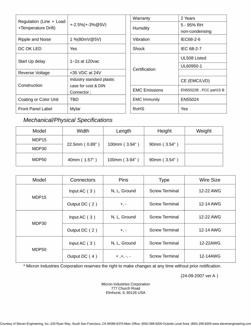
Warranty 2 Years Regulation (Line + Load +Temperature Drift)
+-2.5%(+-3%@5V) Humidity
5 - 95% RH non-condensing
Ripple and Noise 1 %(80mV@5V) Vibration IEC68-2-6
DC OK LED Yes Shock IEC 68-2-7
UL508 Listed Start Up delay 1~2s at 120vac
UL60950-1 Reverse Voltage <35 VDC at 24V
Certification
CE (EMC/LVD) Construction
Industry standard plastic case for cost & DIN Connector ; EMC Emissions EN55022B , FCC part15 B
Coating or Color Unit TBD EMC Immunity EN55024
Front Panel Label Mylar RoHS Yes
Mechanical/Physical Specifications
Model Width Length Height Weight
MDP15
MDP30 22.5mm(0.89”) 100mm(3.94”) 90mm(3.54”)
MDP50 40mm(1.57”) 100mm(3.94”) 90mm(3.54”)
* Micron Industries Corporation reserves the right to make changes at any time without prior notification.
(24-09-2007 ver A)
Micron Industries Corporation 777 Church Road
Elmhurst, IL 60126 USA
Model Connectors Pins Type Wire Size
Input AC(3) N, L, Ground Screw Terminal 12-22 AWG MDP15
Output DC(2) +, - Screw Terminal 12-14 AWG
Input AC(3) N, L, Ground Screw Terminal 12-22 AWG MDP30
Output DC(2) +, - Screw Terminal 12-14 AWG
Input AC(3) N, L, Ground Screw Terminal 12-22AWG MDP50
Output DC(4) + ,+, -, - Screw Terminal 12-14AWG
Courtesy of Steven Engineering, Inc.-230 Ryan Way, South San Francisco, CA 94080-6370-Main Office: (650) 588-9200-Outside Local Area: (800) 258-9200-www.stevenengineering.com

MD60 Series 60W DINergy™ Power Supply
Features
Compact size, high efficiency and DIN Rail mounting 60°C rated provides full power/no derating required 100-240VAC wide-range auto-selection input Overcurrent, shortcircuit, and overvoltage protection DC OK LED status indicator Parallel operation capable Power boost available for large load start demand Safety meets UL508, UL60950 and IEC60950 CE EN61000-3-2 compliant active PFC filtering EMI meets FCC15 B, EN55022 B and CISPR22 B High reliability, MTBF>200,000 hrs Operating temperature: -10°C to 70°C 5 year warranty
Micron DINergy™ units are suitable for process control systems, mechanical equipment, transport equipment, vending service equipment, building automation, and electronic/electrical instrumentation. Specifications
Model MD60-12-1 MD60-24-1 MD60-48-1 Rated 100-240VAC
Input Voltage Range 85-264VAC
Input Current 0.7A/240VAC, 1.3A/100VAC
Frequency 50-60Hz, ±6%
Inrush Current Typ.<25A Earth Leakage Current <3.5mA Start-up Time <1S Rated Output Voltage/Current 12VDC/4.5A 24VDC/2.5A 48VDC/1.25A
Output Set Point 12.5±0.5% 24.5±0.5% 48.5±0.5%
Courtesy of Steven Engineering, Inc.-230 Ryan Way, South San Francisco, CA 94080-6370-Main Office: (650) 588-9200-Outside Local Area: (800) 258-9200-www.stevenengineering.com
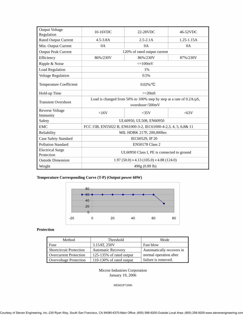
Output Voltage Regulation 10-16VDC 22-28VDC 46-52VDC
Rated Output Current 4.5-3.8A 2.5-2.1A 1.25-1.15A Min. Output Current 0A 0A 0A Output Peak Current 120% of rated output current Efficiency 86%/230V 86%/230V 87%/230V Ripple & Noise <=100mV Load Regulation 1% Voltage Regulation 0.5%
Temperature Coefficient 0.02%/℃
Hold-up Time >=20mS
Transient Overshoot Load is changed from 50% to 100% step by step at a rate of 0.2A/µS,
overshoot<500mV Reverse Voltage Immunity <16V <35V <63V
Safety UL60950, UL508, EN60950 EMC FCC 15B, EN55022 B, EN61000-3-2, IEC61000-4-2,3, 4, 5, 6,8& 11 Reliability MIL HDBK 217F, 200,000hrs Case Safety Standard IEC60529, IP 20 Pollution Standard EN50178 Class 2 Electrical Surge Protection UL60950 Class I, PE is connected to ground
Outside Dimension 1.97 (50.0) ╳ 4.13 (105.0) ╳ 4.88 (124.0) Weight 490g (0.89 lb)
Temperature Corresponding Curve (T-P) (Output power 60W)
020406080
-20 0 20 40 60 80
Protection
Method Threshold Mode Fuse 3.15AT, 250V Fast blow Shortcircuit Protection Automatic Recovery Overcurrent Protection 125-135% of rated output Overvoltage Protection 110-130% of rated output
Automatically recovers in normal operation after failure is removed.
Micron Industries Corporation
January 19, 2006
MD602P72006
Courtesy of Steven Engineering, Inc.-230 Ryan Way, South San Francisco, CA 94080-6370-Main Office: (650) 588-9200-Outside Local Area: (800) 258-9200-www.stevenengineering.com
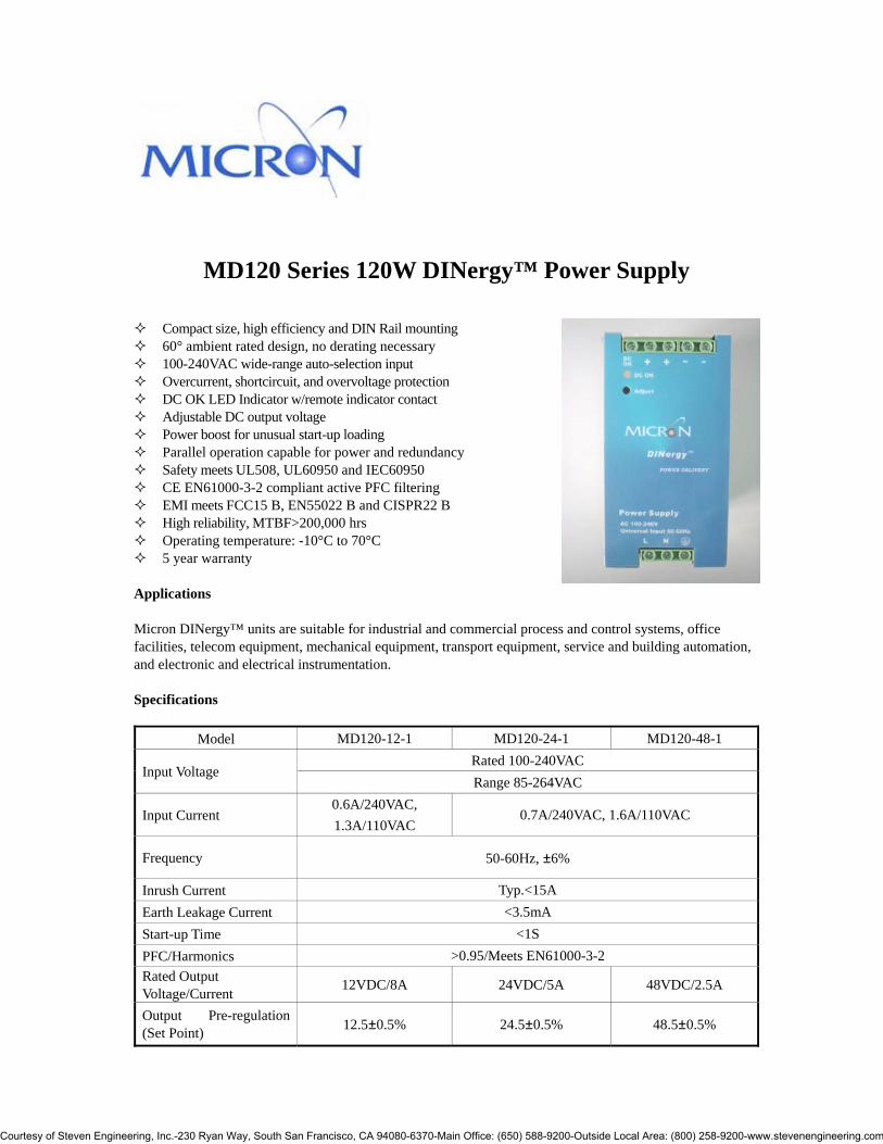
MD120 Series 120W DINergy™ Power Supply
Compact size, high efficiency and DIN Rail mounting 60° ambient rated design, no derating necessary 100-240VAC wide-range auto-selection input Overcurrent, shortcircuit, and overvoltage protection DC OK LED Indicator w/remote indicator contact Adjustable DC output voltage Power boost for unusual start-up loading Parallel operation capable for power and redundancy Safety meets UL508, UL60950 and IEC60950 CE EN61000-3-2 compliant active PFC filtering EMI meets FCC15 B, EN55022 B and CISPR22 B High reliability, MTBF>200,000 hrs Operating temperature: -10°C to 70°C 5 year warranty
Applications Micron DINergy™ units are suitable for industrial and commercial process and control systems, office facilities, telecom equipment, mechanical equipment, transport equipment, service and building automation, and electronic and electrical instrumentation. Specifications
Model MD120-12-1 MD120-24-1 MD120-48-1 Rated 100-240VAC
Input Voltage Range 85-264VAC
Input Current 0.6A/240VAC, 1.3A/110VAC
0.7A/240VAC, 1.6A/110VAC
Frequency 50-60Hz, ±6%
Inrush Current Typ.<15A Earth Leakage Current <3.5mA Start-up Time <1S PFC/Harmonics >0.95/Meets EN61000-3-2 Rated Output Voltage/Current 12VDC/8A 24VDC/5A 48VDC/2.5A
Output Pre-regulation (Set Point) 12.5±0.5% 24.5±0.5% 48.5±0.5%
Courtesy of Steven Engineering, Inc.-230 Ryan Way, South San Francisco, CA 94080-6370-Main Office: (650) 588-9200-Outside Local Area: (800) 258-9200-www.stevenengineering.com

Output Voltage Regulation 10-16VDC 22-28VDC 46-52VDC
Rated Output Current 8-6A 5-4.3A 2.5-2.3A Min. Output Current 0A 0A 0A Output Peak Current 120% of rated output current Efficiency 86%/230V 88%/230V 88%/230V Ripple & Noise <=100mV Load Regulation 1% Voltage Regulation 0.5%
Temperature Coefficient 0.02%/℃
Hold-up Time >=20mS
Transient Overshoot Load is changed from 50% to 100% step by step at a rate of 0.2A/µS,
overshoot<500mV Reverse Voltage Immunity <16V <35V <63V
Safety UL60950, UL508, EN60950 EMC FCC 15B, EN55022 B, EN61000-3-2, IEC61000-4-2,3, 4, 5, 6,8& 11 Reliability MIL HDBK 217F, 200,000hrs Case Safety Standard IEC60529, IP 20 Pollution Standard EN50178 Class 2 Electrical Surge Protection UL60950 Class I, PE is connected to ground
Outside Dimension 2.56 (65.0) ╳ 4.13 (105.0) ╳ 4.89 (124.0) Weight 750g (1.37 lb)
Temperature Corresponding Curve (T-P) (Output power 120W)
0
50
100
150
-20 0 20 40 60 80
Protection
Method Threshold Mode Fuse 3.15AT, 250V Delay Shortcircuit Protection Automatic Recovery Overcurrent Protection 125-135% of rated output Overvoltage Protection 110-130% of rated output Overheat Protection 95℃
Automatically recovers to normal operation after failure is removed.
Micron Industries Corporation
January 19, 2006 MD1202P42006
Courtesy of Steven Engineering, Inc.-230 Ryan Way, South San Francisco, CA 94080-6370-Main Office: (650) 588-9200-Outside Local Area: (800) 258-9200-www.stevenengineering.com

MD240 Series 240W DINergy™ Power Supply
Features
100-240VAC wide-range autoselect input Compact size, high efficiency and DIN Rail mounting Active PFC meets EN61000-3-2 Overcurrent, shortcircuit, overvoltage and overheat protection DC OK LED and active output terminal for remote status check Power boost available for start up load demand Parallel operation (increase output power or redundant operation) UL508, UL60950 and IEC60950 EMI meets FCC15 B, EN55022 B and CISPR22 B High reliability, MTBF>200,000 hrs 5 year warranty
Applications Micron DINergy™ power supplies are suitable for process control systems, mechanical equipment, transport equipment, vending service equipment, building automation, and electronic/electrical instrumentation. Specifications
Model MD240-12-1 MD240-24-1 MD240-48-1 Rated 100-240VAC
Input Voltage Range 85-264VAC
Input Current 3A/100VAC,
1.3A/240VAC 3.5A/100VAC, 1.6A/240VAC
Frequency 50-60Hz, ±6%
Inrush Current Typ.<15A Earth Leakage Current <3.5mA Start-up Time <1S PFC/Harmonics >0.95/Meets EN61000-3-2 Rated Output Voltage/Current 12VDC/15A 24VDC/10A 48VDC/5A
Output Pre-regulation (Set Point) 12.5±0.5% 24.5±0.5% 48.5±0.5%
Courtesy of Steven Engineering, Inc.-230 Ryan Way, South San Francisco, CA 94080-6370-Main Office: (650) 588-9200-Outside Local Area: (800) 258-9200-www.stevenengineering.com

Output Voltage Regulation 10-16VDC 22-28VDC 46-52VDC
Rated Output Current 15-11.3A 10-8.6A 5-4.6A Min. Output Current 0A 0A 0A Output Peak Current 120% of rated output current Efficiency 86%/230V 88%/230V 88%/230V Ripple & Noise <=100mV Load Regulation 1% Voltage Regulation 0.5%
Temperature Coefficient 0.02%/℃
Hold-up Time >=20mS
Transient Overshoot Load is changed from 50% to 100% step by step at a rate of 0.2A/µS,
overshoot<500mV Reverse Voltage Immunity <16V <35V <63V
Safety UL60950, UL508, EN60950 EMC FCC 15B, EN55022 B, EN61000-3-2, IEC61000-4-2,3, 4, 5, 6,8& 11 Reliability MIL HDBK 217F, 200,000hrs Case Safety Standard IEC60529, IP 20 Pollution Standard EN50178 Class 2 Electrical Surge Protection UL60950 Class I, PE is connected to ground
Outside Dimension 3.43 (87.0) ╳ 5.13 (130.0) ╳ 4.88 (124.0) Weight 1,300g (2.37 lb)
Temperature Corresponding Curve (T-P) (Output power 240W)
0100200300
- 20 - 10 0 10 20 30 40 50 60 70 80
Protection
Method Threshold Mode Fuse 6.3AT, 250V Delay Shortcircuit Protection Automatic Recovery Overcurrent Protection 125-135% of rated output Overvoltage Protection 110-130% of rated output Overheat Protection 105℃
Automatically recovers to normal operation after failure is removed.
Micron Industries Corporation
January 19, 2006
MD2402P42006
Courtesy of Steven Engineering, Inc.-230 Ryan Way, South San Francisco, CA 94080-6370-Main Office: (650) 588-9200-Outside Local Area: (800) 258-9200-www.stevenengineering.com

MD480 Series 480W DINergy™ Power Supply
Features
100-240VAC wide-range auto-select input (no switches) Compact size, high efficiency and DIN Rail mounting 60°C rated design, -10° through 70°C operating range Active PFC meets EN61000-3-2 Overcurrent, shortcircuit, overvoltage, overheat protection DC OK LED and active output terminal for remote check Power boost provided for large start up demand Parallel for increased output power or redundant operation Safety meets UL508, UL60950 and IEC60950 EMI meets FCC15 B, EN55022 B and CISPR22 B High reliability, MTBF>200,000 hrs 5 year limited warranty
Applications Micron DINergy™ power supplies are suitable for process control systems, mechanical equipment, transport equipment, vending service equipment, building automation, and electronic/electrical instrumentation. Specifications
Model MD480-24-1 MD480-36-1 MD480-48-1 Rated 100-240VAC
Input Voltage Range 85-264VAC
Input Current 6.3A/100VAC, 2.6A/240VAC
Frequency 50-60Hz, ±6%
Inrush Current Typ.<30A Earth Leakage Current <3.5mA Start-up Time <1S PFC/Harmonics >0.95/Meets EN61000-3-2 Rated Output Voltage/Current 24VDC/20A 36VDC/13.3A 48VDC/10A
Output Pre-regulation (Set Point) 24.5±0.5% 36.5±0.5% 48.5±0.5%
Courtesy of Steven Engineering, Inc.-230 Ryan Way, South San Francisco, CA 94080-6370-Main Office: (650) 588-9200-Outside Local Area: (800) 258-9200-www.stevenengineering.com
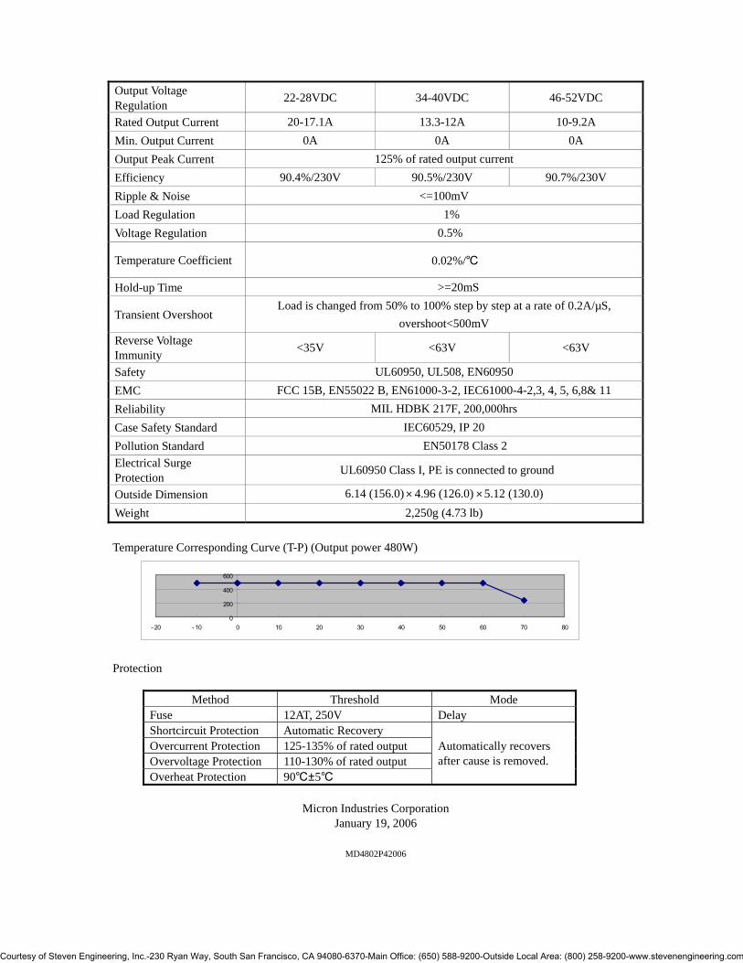
Output Voltage Regulation 22-28VDC 34-40VDC 46-52VDC
Rated Output Current 20-17.1A 13.3-12A 10-9.2A Min. Output Current 0A 0A 0A Output Peak Current 125% of rated output current Efficiency 90.4%/230V 90.5%/230V 90.7%/230V Ripple & Noise <=100mV Load Regulation 1% Voltage Regulation 0.5%
Temperature Coefficient 0.02%/℃
Hold-up Time >=20mS
Transient Overshoot Load is changed from 50% to 100% step by step at a rate of 0.2A/µS,
overshoot<500mV Reverse Voltage Immunity <35V <63V <63V
Safety UL60950, UL508, EN60950 EMC FCC 15B, EN55022 B, EN61000-3-2, IEC61000-4-2,3, 4, 5, 6,8& 11 Reliability MIL HDBK 217F, 200,000hrs Case Safety Standard IEC60529, IP 20 Pollution Standard EN50178 Class 2 Electrical Surge Protection UL60950 Class I, PE is connected to ground
Outside Dimension 6.14 (156.0) ╳ 4.96 (126.0) ╳ 5.12 (130.0) Weight 2,250g (4.73 lb) Temperature Corresponding Curve (T-P) (Output power 480W)
0
200
400
600
- 20 - 10 0 10 20 30 40 50 60 70 80
Protection
Method Threshold Mode Fuse 12AT, 250V Delay Shortcircuit Protection Automatic Recovery Overcurrent Protection 125-135% of rated output Overvoltage Protection 110-130% of rated output Overheat Protection 90℃±5℃
Automatically recovers after cause is removed.
Micron Industries Corporation
January 19, 2006
MD4802P42006
Courtesy of Steven Engineering, Inc.-230 Ryan Way, South San Francisco, CA 94080-6370-Main Office: (650) 588-9200-Outside Local Area: (800) 258-9200-www.stevenengineering.com

MD-PSRM DINergy™ Power Supply Diode Module for Redundant Configuration
(Available December 2006)
Micron DINergy™ power supplies can be connected in parallel to provide redundant rated output power and voltage for fail-safe requirements. To achieve this, a user may connect two identical Micron units with equal output voltage settings, connecting a Micron redundancy module MD-PSRM to prevent back-feeding or looping in the event of failure of one of the units. The MD-PSRM consists of a diode array and sensing/switching components enclosed within a DIN rail mounting metal case, and is equal in size to a 60w DINergy power supply.
Common appearance with DINergy™ power supply family Compact size and DIN Rail mounting
Outside Dimension in.(mm) 1.97 (50.0) ╳ 4.13 (105.0) ╳ 4.88 (124.0) Weight 275g (0.50 lb)
To increase reliability of system, use two power supplies of the same model for redundancy operation. Use load connection wires of the same gauge and length. Set the output voltages of all units to the same values. Connect decoupling diode module MD-PSRM to the positive outputs of the paralleled units. In normal state, each unit provides 50% of load current. When failure occurs on the circuit of the unit 1, unit 2 is able to immediately and automatically replace unit 1 to continue the operation at 100% rated current. The same will be true if the failure occurs on circuit of unit 2.
MICRON DINergy™
DIODE MODULE
MD-PSRM
REDUNDANT CONNECTION FOR
Courtesy of Steven Engineering, Inc.-230 Ryan Way, South San Francisco, CA 94080-6370-Main Office: (650) 588-9200-Outside Local Area: (800) 258-9200-www.stevenengineering.com

Mounting Method A TS35/7.5 or TS35/15 rail of certain length corresponding to the width of the unit is provided for convenient DIN rail mounting. MICRON MD-PSRM CONNECTION DIAGRAM/SCHEMATIC
Micron Industries Corporation 800-664-4660
[email protected] www.microntransformers.com
MDPSRM2P42006
Courtesy of Steven Engineering, Inc.-230 Ryan Way, South San Francisco, CA 94080-6370-Main Office: (650) 588-9200-Outside Local Area: (800) 258-9200-www.stevenengineering.com

Product Data Sheet
DIN Rail DC–Sag UPS with Backup Battery
Micron DINergy™
DIN Rail
DC–Sag-UPS Module
24VDC, 10 Amp External Battery Option
KEY FEATURES
• No-Maintenance Sag Protection No fans for high MBTF
• Optional External Backup Battery Pack. Up to 10 minutes (extra Battery Packs available separately)
”DC OK” Signal
• Industrial Design and Construction; Compact Size with Rugged Metal Case • ”CHARGING” Indicator LED
• Standard DIN Mounting • Circuit and Damage Protection
• 700 msec. Backup at 10A, (no Ext. Battery) 4 min. Backup at 10A (with Ext. Battery)
• Meets: UL/C-UL, EN 50081-2, EN 61000-6-2
DESCRIPTION DC Power is a critical energy to most automation solutions today. Loss of power can collapse data communication, diminishing product and process quality, and system productivity. Micron gives customers the ability to increase this 24Volt DC availability by the use of its DC Sag Buffer/UPS product. The DC-Sag Buffer/UPS (Sag Buffer plus Uninterruptible Power Supply) can help equipment ride through many nuisance sags and help provide orderly shutdown in a more sustained power loss. . The DC Sag Buffer/UPS uniquely takes the guesswork out of power availability to DC control systems and equipment, especially where power issues are difficult to quantify. Featuring a unique two stage Sag-buffer plus optional Battery back-up function, customers can tailor their power availability needs from milliseconds to minutes depending on their environment, location, or equipment. The DC Sag Buffer/UPS features a 24V buffer stage that protects against one of the most common forms of power quality problems: the sag. Using maintenance-free, ultra capacitors, the unit can provide up from 700ms to 10 seconds of hold-up (load dependent). For increased hold-up time, an integral battery charger allows the user to add batteries for hold-up up from 4 - 10 minutes. Customers can purchase the unit for sag protection, and if longer run times are required, buy the optional DIN Rail mount battery packs. The DC Sag Buffer/UPS is a compact, highly reliable solution to DC availability. The life expectancy of the product is extremely high when compared to its AC UPS competition due to its Industrial temperature range, zero fans, a lower component count, and the optional/replaceable batteries. The DC Sag Buffer/UPS complements a broad range of Industrial DC Power Supplies to gives its customers the ultimate in DC power reliability.
Courtesy of Steven Engineering, Inc.-230 Ryan Way, South San Francisco, CA 94080-6370-Main Office: (650) 588-9200-Outside Local Area: (800) 258-9200-www.stevenengineering.com

Product Data Sheet
MODEL SELECTION GUIDE
DCSagUPS Model Configuration Rating Battery
MDBPS-1024L DC-UPS (with External Battery) 10 Amps / 2.6 AH Sealed Lead Acid
MDBPS-(tbd) DC-UPS Module only 10 Amps N/A
MDBPS-BATTERYL24 External Battery only 10 Amps / 2.6 AH Sealed Lead Acid
SPECIFICATIONS
NOTE: Products are rated for industrial environments and are not to be used nor are warranted in aerospace, medical or life safety applications.
GENERAL (DC-UPS with External Battery)
Operating Temperature 0 to +75 C Weight 2.5 lbs (1.13 kg): DC-UPS 6.0 lbs (2.7 kg): Ext. Batt.
Storage Temperature –15 to +75 C Vibration / Shock 2.3g, 90min / 30g
Relative Humidity (25C) ≤ 95%RH, non-condensing Certifications
Meets: UL/C-UL(60950) EN 50081-2, EN 61000-6-2
Courtesy of Steven Engineering, Inc.-230 Ryan Way, South San Francisco, CA 94080-6370-Main Office: (650) 588-9200-Outside Local Area: (800) 258-9200-www.stevenengineering.com

Product Data Sheet
ELECTRICAL DC-UPS Module (1)
Rated DC Input 24 VDC +/- 5%, 11 A (Internal usage: < 1 A) DC Output Transition < 0.8 ms, with
< -10% DC output drop
Rated DC Output 24 VDC +/- 10%, 10 A DC Output Protection Front Access Fuse, 12A
Charger Output (1) 27.3 VDC, ≤ 0.5 A
Charging Time (1) 4 Hr. max. Battery Status “ CHARGING ” LED ” DC OK ” Signal (open collector, 5 mA)
Low Voltage Trip Points (falling / recovering) 22.7 VDC / 22.8 VDC Connections See Mechanical Dwg.
Low Voltage Boost ≥ 22.1 VDC MTBF > 500,000 Hrs
Low Voltage Shutdown ≤ 19.8 VDC Battery & ≤ 22.3 VDC DC Input Warranty 2 years
External Battery Module (1)
Battery Type Sealed Lead Acid Connectors See Mechanical Dwg.
Rating 24VDC, 2.6 AH / 20 Hr Warranty 1 Year
(1) For Battery protection against damage, the external charger source connected to the Sealed Lead Acid Backup Battery module must only be the DC-UPS model MDBPS-1024L charger.
OUTPUT TRANSITION (supply power to battery power; at 10 Amps load)
OUTPUT CURRENT HOLD TIME
Output Load Current No External Battery With External Battery
5 Amps 2 sec 10 min
10 Amps 0.7 sec 4 min
Boost Voltage
Backup
DC IN
Transition Voltage
Low Voltage Trip SettingNormal
Charged
Boost Setting Shutoff Setting
DC Power Supply IN
External Battery IN
UPS Power OUT
Transition Time
(shutdown)
Courtesy of Steven Engineering, Inc.-230 Ryan Way, South San Francisco, CA 94080-6370-Main Office: (650) 588-9200-Outside Local Area: (800) 258-9200-www.stevenengineering.com

Product Data Sheet
OPERATION As shown in the diagram above, the 24 VDC Input External Power Supply feeds the Charger. The Charger charges the Holdup Storage capacitor and the (optional) External Backup Battery. When the DC Input voltage becomes low, the DC-UPS switches the DC Output to the Battery source. The Linear Regulator and Boost Regulator work together to convert the energy of the Holdup Storage and Backup Battery to a regulated Holdup output voltage.
• NORMAL – When the 24 VDC Input power source is normal and above the low voltage trip point, the DC Input voltage is routed to the DC Output terminals.
• LOW VOLTAGE – When the 24 VDC Input power source fails or a transient occurs below the “Boost”
trip point, the DC-UPS switches to the Internal Storage or optional Backup Battery source. The Linear Regulator and Boost Regulator maintain the DC Output energy at the Boost Voltage.
• SHUTDOWN – When the Holdup Buffer storage capacitor or (optional) External Backup Battery falls
below the “Automatic Shutdown” point, the DC-OK Detection circuit automatically shuts off the DC Output. This protects the Battery from persistent overload and possible damage.
• RECOVERY – If Input power source should recover, the Holdup circuit will resume normal operation
and the Charger will resume charging the External Backup Battery.
BLOCK DIAGRAM
IN DC-OK OUT
“CHARGING” LED
CHARGER
EXTERNAL DC POWER SUPPLY
“DC-OK” DETECT
EXTERNAL BACKUP BATTERY
HOLDUP STORAGE
LINEAR REGULATOR
& SHUTDOWN SWITCH
BOOST REGULATOR
Courtesy of Steven Engineering, Inc.-230 Ryan Way, South San Francisco, CA 94080-6370-Main Office: (650) 588-9200-Outside Local Area: (800) 258-9200-www.stevenengineering.com

Product Data Sheet
Copyright 2006 Micron Industries Corp. Micron Industries Corp. reserves the right to make changes in the product at any time, without notification. DC-UPS Datasheet - REV1.doc 05 December 2006
BATTERY STATUS
LED DC OK Signal
ON – Normal DC Input, Backup source is charging CONDUCTING (5ma) – DC Input is Normal.
OFF – Low Voltage DC Input, Backup source is not charging OPEN (Bvce 36V) – DC Input is not Normal.
MECHANICAL (not to scale)
CONNECTIONS
TERMINAL DESCRIPTION
IN 24V 24 VDC External Power Input (+/–).
OUT 24V 24 VDC Output Load (+/–).
DC–OK Open Collector output signal (+/–).
UPS / Battery Cable 24 VDC (+/–) between UPS and Battery only.
Micron Industries Corporation 777 Church Road Elmhurst, IL 60126
Main: 630 516-1222 Sales: 800 664-4660 Tech Support: 800 664-4660 Fax: 630 516-1820
Website: General Email: Sales & Quotation Email:
http://www.microntransformers.com [email protected] [email protected]
Typ Length: 7.5 (190.5)
3.0 (76)
0.8 (20)
5.12 (130)
0.8 (20)
3.9 (100) 0.7 (18)
4.7 (119)
Backup Battery
UPS / Battery Connection
Input, Load, DC-Monitor Connections
Fuse
DC - UPS
LED Fuse
4.6 (116)
Courtesy of Steven Engineering, Inc.-230 Ryan Way, South San Francisco, CA 94080-6370-Main Office: (650) 588-9200-Outside Local Area: (800) 258-9200-www.stevenengineering.com

Catalog CCT-08A Effective: 02/08
Micron ImperviPOWER 67™ Power Supply Selection Guide
Model
Output Power (Watts)
Input Voltage (VAC)
Output Voltage (VDC)
Efficiency Rating
Ambient Temp Rating
Size WxDxH(mm)
MIP67-50-24 50 90-264 24 ≥88% -40C to +50C 166x85x35MIP67-100-24 100 90-264 24 ≥88% -40C to +50C 166x85x35CONSULT MICRON FOR FACTORY AVAILABILITYALL UNITS HAVE AN ISOLATION RATING OF 3.3KVACCONTACT MICRON FOR SPECIFIC DETAILS ON THE IMPERVIPOWER 67 LINE
29
Courtesy of Steven Engineering, Inc.-230 Ryan Way, South San Francisco, CA 94080-6370-Main Office: (650) 588-9200-Outside Local Area: (800) 258-9200-www.stevenengineering.com

Catalog CCT-08A Effective: 02/08
DRY TYPE TRANSFORMERSGENERAL INFORMATION
Micron can provide a general purpose or buck-boost transformer to satisfy your industrial or commercial application. Please refer to Catalog number LVGP-904 for further information
30
Courtesy of Steven Engineering, Inc.-230 Ryan Way, South San Francisco, CA 94080-6370-Main Office: (650) 588-9200-Outside Local Area: (800) 258-9200-www.stevenengineering.com

Micron Industries Corporation 777 North Church Road Elmhurst, IL 60126 Phone: 800-664-4660 FAX: 630-516-1820 www.microntransformers.com
Courtesy of Steven Engineering, Inc.-230 Ryan Way, South San Francisco, CA 94080-6370-Main Office: (650) 588-9200-Outside Local Area: (800) 258-9200-www.stevenengineering.com