Embed Size (px)
Citation preview
— C ATALOG
ABB drives for water and wastewaterACQ580, 0.75 to 500 kW

2 A B B D R I V E S FO R WATE R A N D WA S TE WATE R ACQ5 8 0, 0 .75 TO 5 0 0 K W
— ACQ580 series Always flowing. Never still.
Water utilities require reliable solutions securing the flow of water and wastewater.
The ACQ580 drive for water is part of ABB’sall-compatible drives portfolio. This robust drive is designed to secure optimal operation of water and wastewater pumps, while ensuring low energyconsumption.
3
— Contents
004 The energy efficient drive for water and wastewater pumping006 All-compatible solutions for water and wastewater applications008 Optimizing the flow of water and wastewater in your pumping solutions010 Securing the flow of water and wastewater in the pump system012 How to select a drive?013 Technical specification014 Securing the flow of water and wastewater with the ACQ580015 Complete offering from wall-mounted drives to cabinet installations016 Ratings, types and voltages019 Dimensions020 Pump control program021 Comprehensive connectivity022 Built-in pump application software023 Ultimate efficiency and reliability to minimize your system cost of ownership024 Selection guide026 Effortless drive commissioning and use with control panels027 Save time, ease troubleshooting and improve drive performance with ABB smartphone apps028 High protection for operation in harsh environments029 Quick configuration for unpowered drives030 Flexible connectivity to automation networks031 Input/output extension and thermistor protection modules for increased connectivity and safety032 EMC – electromagnetic compatibility033 du/dt filters035 Cooling and fuses037 Choose the motor for your water application038 ABB automation products040 Services to match your needs042 A lifetime of peak performance
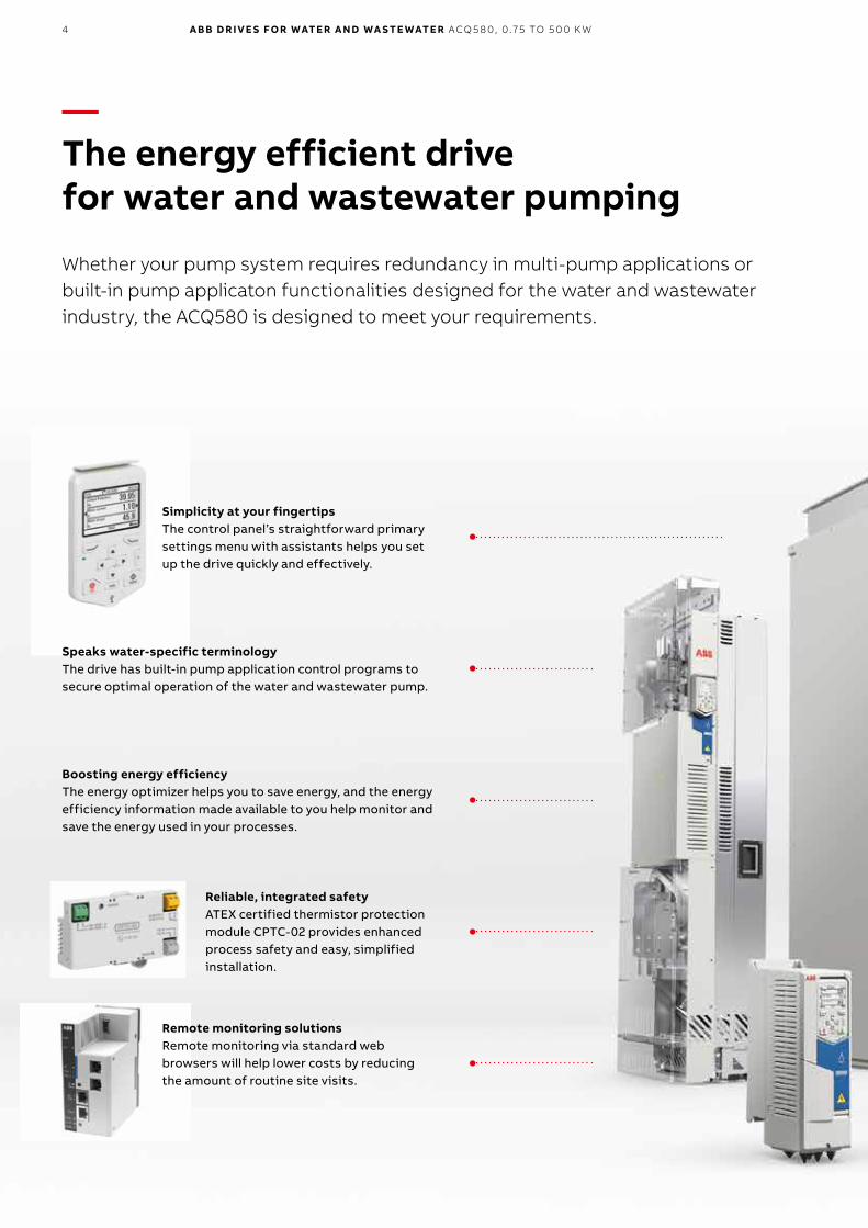
Reliable, integrated safetyATEX certified thermistor protection module CPTC-02 provides enhanced process safety and easy, simplified installation.
4 A B B D R I V E S FO R WATE R A N D WA S TE WATE R ACQ5 8 0, 0 .75 TO 5 0 0 K W
—The energy efficient drive for water and wastewater pumping
Whether your pump system requires redundancy in multi-pump applications or built-in pump applicaton functionalities designed for the water and wastewater industry, the ACQ580 is designed to meet your requirements.
Simplicity at your fingertipsThe control panel’s straightforward primary settings menu with assistants helps you set up the drive quickly and effectively.
Boosting energy efficiencyThe energy optimizer helps you to save energy, and the energy efficiency information made available to you help monitor and save the energy used in your processes.
Speaks water-specific terminologyThe drive has built-in pump application control programs to secure optimal operation of the water and wastewater pump.
Remote monitoring solutionsRemote monitoring via standard web browsers will help lower costs by reducing the amount of routine site visits.
5
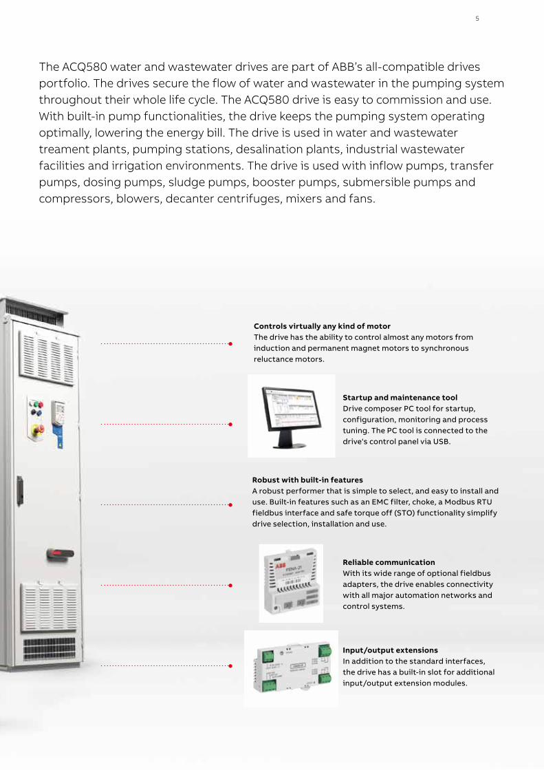
The ACQ580 water and wastewater drives are part of ABB’s all-compatible drives portfolio. The drives secure the flow of water and wastewater in the pumping system throughout their whole life cycle. The ACQ580 drive is easy to commission and use. With built-in pump functionalities, the drive keeps the pumping system operating optimally, lowering the energy bill. The drive is used in water and wastewater treament plants, pumping stations, desalination plants, industrial wastewater facilities and irrigation environments. The drive is used with inflow pumps, transfer pumps, dosing pumps, sludge pumps, booster pumps, submersible pumps and compressors, blowers, decanter centrifuges, mixers and fans.
Controls virtually any kind of motor The drive has the ability to control almost any motors from induction and permanent magnet motors to synchronous reluctance motors.
Startup and maintenance toolDrive composer PC tool for startup, configuration, monitoring and process tuning. The PC tool is connected to the drive‘s control panel via USB.
Robust with built-in featuresA robust performer that is simple to select, and easy to install and use. Built-in features such as an EMC filter, choke, a Modbus RTU fieldbus interface and safe torque off (STO) functionality simplify drive selection, installation and use.
Reliable communicationWith its wide range of optional fieldbus adapters, the drive enables connectivity with all major automation networks and control systems.
Input/output extensionsIn addition to the standard interfaces, the drive has a built-in slot for additional input/output extension modules.
6 A B B D R I V E S FO R WATE R A N D WA S TE WATE R ACQ5 8 0, 0 .75 TO 5 0 0 K W
—All-compatible solutions for water and wastewater applications
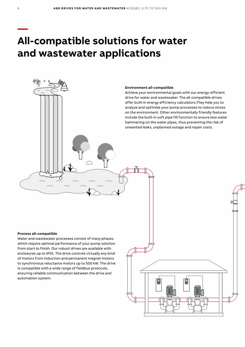
Environment all-compatibleAchieve your environmental goals with our energy-efficient drive for water and wastewater. The all-compatible drives offer built-in energy efficiency calculators.They help you to analyze and optimize your pump processes to reduce stress on the environment. Other environmentally friendly features include the built-in soft pipe fill function to ensure less water hammering on the water pipes, thus preventing the risk of unwanted leaks, unplanned outage and repair costs.
Process all-compatibleWater and wastewater processes consist of many phases which require optimal performance of your pump solution from start to finish. Our robust drives are available with enclosures up to IP55. The drive controls virtually any kind of motors from induction and permanent magnet motors to synchronous reluctance motors up to 500 kW. The drive is compatible with a wide range of fieldbus protocols, ensuring reliable communication between the drive and automation system.
7
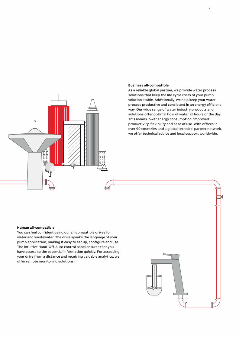
Business all-compatibleAs a reliable global partner, we provide water process solutions that keep the life cycle costs of your pump solution stable. Additionally, we help keep your water process productive and consistent in an energy efficient way. Our wide range of water industry products and solutions offer optimal flow of water all hours of the day. This means lower energy consumption, improved productivity, flexibility and ease of use. With offices in over 90 countries and a global technical partner network, we offer technical advice and local support worldwide.
Human all-compatibleYou can feel confident using our all-compatible drives for water and wastewater. The drive speaks the language of your pump application, making it easy to set up, configure and use. The intuitive Hand-Off-Auto control panel ensures that you have access to the essential information quickly. For accessing your drive from a distance and receiving valuable analytics, we offer remote monitoring solutions.
8 A B B D R I V E S FO R WATE R A N D WA S TE WATE R ACQ5 8 0, 0 .75 TO 5 0 0 K W
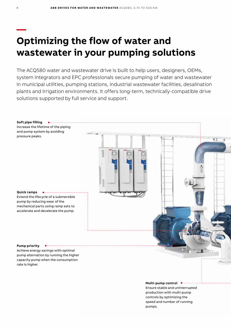
Quick rampsExtend the lifecycle of a submersible pump by reducing wear of the mechanical parts using ramp sets to accelerate and decelerate the pump.
—Optimizing the flow of water and wastewater in your pumping solutions
The ACQ580 water and wastewater drive is built to help users, designers, OEMs, system integrators and EPC professionals secure pumping of water and wastewater in municipal utilities, pumping stations, industrial wastewater facilities, desalination plants and irrigation environments. It offers long-term, technically-compatible drive solutions supported by full service and support.
Soft pipe fillingIncrease the lifetime of the piping and pump system by avoiding pressure peaks.
Multi-pump controlEnsure stable and uninterrupted production with multi-pump controls by optimizing the speed and number of running pumps.
Pump priorityAchieve energy savings with optimal pump alternation by running the higher capacity pump when the consumption rate is higher.
9
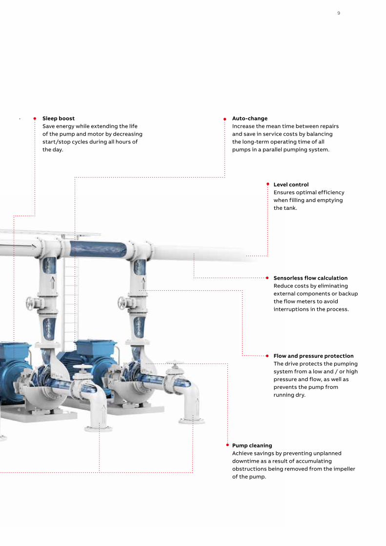
Auto-changeIncrease the mean time between repairs and save in service costs by balancing the long-term operating time of all pumps in a parallel pumping system.
Sensorless flow calculationReduce costs by eliminatingexternal components or backupthe flow meters to avoidinterruptions in the process.
Flow and pressure protection The drive protects the pumping system from a low and / or high pressure and flow, as well as prevents the pump from running dry.
Level controlEnsures optimal efficiency when filling and emptying the tank.
Sleep boostSave energy while extending the life of the pump and motor by decreasing start/stop cycles during all hours of the day.
Pump cleaningAchieve savings by preventing unplanned downtime as a result of accumulating obstructions being removed from the impeller of the pump.
10 A B B D R I V E S FO R WATE R A N D WA S TE WATE R ACQ5 8 0, 0 .75 TO 5 0 0 K W
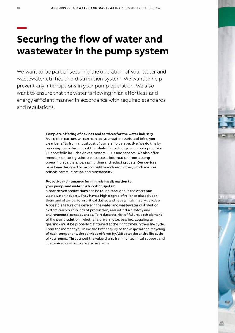
—Securing the flow of water and wastewater in the pump system
Complete offering of devices and services for the water industryAs a global partner, we can manage your water assets and bring you clear benefits from a total cost of ownership perspective. We do this by reducing costs throughout the whole life cycle of your pumping solution. Our portfolio includes drives, motors, PLCs and sensors. We also offer remote monitoring solutions to access information from a pump operating at a distance, saving time and reducing costs. Our devices have been designed to be compatible with each other, which ensures reliable communication and functionality.
Proactive maintenance for minimizing disruption to your pump and water distribution systemMotor-driven applications can be found throughout the water and wastewater industry. They have a high degree of reliance placed upon them and often perform critical duties and have a high in-service value. A possible failure of a device in the water and wastewater distribution system can result in loss of production, and introduce safety and environmental consequences. To reduce the risk of failure, each element of the pump solution - whether a drive, motor, bearing, coupling or gearing - must be properly maintained at the right times in their life cycle. From the moment you make the first enquiry to the disposal and recycling of each component, the services offered by ABB span the entire life cycle of your pump. Throughout the value chain, training, technical support and customized contracts are also available.
We want to be part of securing the operation of your water and wastewater utilities and distribution system. We want to help prevent any interruptions in your pump operation. We also want to ensure that the water is flowing in an effortless and energy efficient manner in accordance with required standards and regulations.
11
12 A B B D R I V E S FO R WATE R A N D WA S TE WATE R ACQ5 8 0, 0 .75 TO 5 0 0 K W
—ACQ580-01
16 A B B D R I V E S FO R WATE R A N D WA S TE WATE R ACQ5 8 0, 0 .75 TO 5 0 0 K W
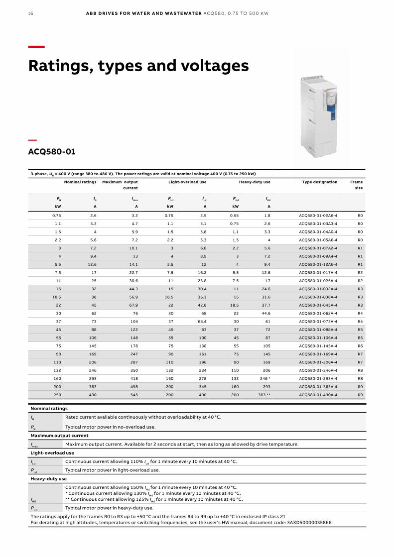
—Ratings, types and voltages
Nominal ratings
IN Rated current available continuously without overloadability at 40 °C.
PN Typical motor power in no-overload use.
Maximum output current
Imax Maximum output current. Available for 2 seconds at start, then as long as allowed by drive temperature.
Light-overload use
ILd Continuous current allowing 110% ILd for 1 minute every 10 minutes at 40 °C.
PLd Typical motor power in light-overload use.
Heavy-duty use
IHd
Continuous current allowing 150% IHd for 1 minute every 10 minutes at 40 °C.* Continuous current allowing 130% IHd for 1 minute every 10 minutes at 40 °C.** Continuous current allowing 125% IHd for 1 minute every 10 minutes at 40 °C.
PHd Typical motor power in heavy-duty use.
The ratings apply for the frames R0 to R3 up to +50 °C and the frames R4 to R9 up to +40 °C in enclosed IP class 21For derating at high altitudes, temperatures or switching frequencies, see the user‘s HW manual, document code: 3AXD50000035866.
3-phase, UN = 400 V (range 380 to 480 V). The power ratings are valid at nominal voltage 400 V (0.75 to 250 kW)
Nominal ratings
Maximum output current
Light-overload use
Heavy-duty use Type designation Frame size
PN IN Imax PLd ILd PHd IHd
kW A A kW A kW A
0.75 2.6 3.2 0.75 2.5 0.55 1.8 ACQ580-01-02A6-4 R0
1.1 3.3 4.7 1.1 3.1 0.75 2.6 ACQ580-01-03A3-4 R0
1.5 4 5.9 1.5 3.8 1.1 3.3 ACQ580-01-04A0-4 R0
2.2 5.6 7.2 2.2 5.3 1.5 4 ACQ580-01-05A6-4 R0
3 7.2 10.1 3 6.8 2.2 5.6 ACQ580-01-07A2-4 R1
4 9.4 13 4 8.9 3 7.2 ACQ580-01-09A4-4 R1
5.5 12.6 14.1 5.5 12 4 9.4 ACQ580-01-12A6-4 R1
7.5 17 22.7 7.5 16.2 5.5 12.6 ACQ580-01-017A-4 R2
11 25 30.6 11 23.8 7.5 17 ACQ580-01-025A-4 R2
15 32 44.3 15 30.4 11 24.6 ACQ580-01-032A-4 R3
18.5 38 56.9 18.5 36.1 15 31.6 ACQ580-01-038A-4 R3
22 45 67.9 22 42.8 18.5 37.7 ACQ580-01-045A-4 R3
30 62 76 30 58 22 44.6 ACQ580-01-062A-4 R4
37 73 104 37 68.4 30 61 ACQ580-01-073A-4 R4
45 88 122 45 83 37 72 ACQ580-01-088A-4 R5
55 106 148 55 100 45 87 ACQ580-01-106A-4 R5
75 145 178 75 138 55 105 ACQ580-01-145A-4 R6
90 169 247 90 161 75 145 ACQ580-01-169A-4 R7
110 206 287 110 196 90 169 ACQ580-01-206A-4 R7
132 246 350 132 234 110 206 ACQ580-01-246A-4 R8
160 293 418 160 278 132 246 * ACQ580-01-293A-4 R8
200 363 498 200 345 160 293 ACQ580-01-363A-4 R9
250 430 545 200 400 200 363 ** ACQ580-01-430A-4 R9
—ACQ580-01
16 A B B D R I V E S FO R WATE R A N D WA S TE WATE R ACQ5 8 0, 0 .75 TO 5 0 0 K W
—Ratings, types and voltages
Nominal ratings
IN Rated current available continuously without overloadability at 40 °C.
PN Typical motor power in no-overload use.
Maximum output current
Imax Maximum output current. Available for 2 seconds at start, then as long as allowed by drive temperature.
Light-overload use
ILd Continuous current allowing 110% ILd for 1 minute every 10 minutes at 40 °C.
PLd Typical motor power in light-overload use.
Heavy-duty use
IHd
Continuous current allowing 150% IHd for 1 minute every 10 minutes at 40 °C.* Continuous current allowing 130% IHd for 1 minute every 10 minutes at 40 °C.** Continuous current allowing 125% IHd for 1 minute every 10 minutes at 40 °C.
PHd Typical motor power in heavy-duty use.
The ratings apply for the frames R0 to R3 up to +50 °C and the frames R4 to R9 up to +40 °C in enclosed IP class 21For derating at high altitudes, temperatures or switching frequencies, see the user‘s HW manual, document code: 3AXD50000035866.
3-phase, UN = 400 V (range 380 to 480 V). The power ratings are valid at nominal voltage 400 V (0.75 to 250 kW)
Nominal ratings
Maximum output current
Light-overload use
Heavy-duty use Type designation Frame size
PN IN Imax PLd ILd PHd IHd
kW A A kW A kW A
0.75 2.6 3.2 0.75 2.5 0.55 1.8 ACQ580-01-02A6-4 R0
1.1 3.3 4.7 1.1 3.1 0.75 2.6 ACQ580-01-03A3-4 R0
1.5 4 5.9 1.5 3.8 1.1 3.3 ACQ580-01-04A0-4 R0
2.2 5.6 7.2 2.2 5.3 1.5 4 ACQ580-01-05A6-4 R0
3 7.2 10.1 3 6.8 2.2 5.6 ACQ580-01-07A2-4 R1
4 9.4 13 4 8.9 3 7.2 ACQ580-01-09A4-4 R1
5.5 12.6 14.1 5.5 12 4 9.4 ACQ580-01-12A6-4 R1
7.5 17 22.7 7.5 16.2 5.5 12.6 ACQ580-01-017A-4 R2
11 25 30.6 11 23.8 7.5 17 ACQ580-01-025A-4 R2
15 32 44.3 15 30.4 11 24.6 ACQ580-01-032A-4 R3
18.5 38 56.9 18.5 36.1 15 31.6 ACQ580-01-038A-4 R3
22 45 67.9 22 42.8 18.5 37.7 ACQ580-01-045A-4 R3
30 62 76 30 58 22 44.6 ACQ580-01-062A-4 R4
37 73 104 37 68.4 30 61 ACQ580-01-073A-4 R4
45 88 122 45 83 37 72 ACQ580-01-088A-4 R5
55 106 148 55 100 45 87 ACQ580-01-106A-4 R5
75 145 178 75 138 55 105 ACQ580-01-145A-4 R6
90 169 247 90 161 75 145 ACQ580-01-169A-4 R7
110 206 287 110 196 90 169 ACQ580-01-206A-4 R7
132 246 350 132 234 110 206 ACQ580-01-246A-4 R8
160 293 418 160 278 132 246 * ACQ580-01-293A-4 R8
200 363 498 200 345 160 293 ACQ580-01-363A-4 R9
250 430 545 200 400 200 363 ** ACQ580-01-430A-4 R9
26 A B B D R I V E S FO R WATE R A N D WA S TE WATE R ACQ5 8 0, 0 .75 TO 5 0 0 K W
—Effortless drive commissioning and use with control panels
Option code Description Type designation
+J429Control panel with Bluetooth interface ACH-AP-W
+J425 Assistant control panel ACS-AP-I
+J424Blank control panel cover (no control panel delivered) CDUM-01
3AXD50000004419 Panel bus adapter CDPI-01
3AUA0000108878
Control panel mounting platform (flush mounted, requires also panel bus adapter on the drive) DPMP-01
3AXD50000009374
Control panel mounting platform (surface mounted, requires also panel bus adapter on the drive) DPMP-02
3AXD50000010763
Door mounting kit for the panel (for one drive, contains both DPMP-02 and CDPI-01) DPMP-EXT
—Control panel optionsThe Hand-Off-Auto control panel ACH-AP-H is included as standard in the delivery unless otherwise specified.
—03
—02
—01
Effortless drive setup − The primary settings menu with
embedded assistants provides a smart and quick way to set up the drive.
− Each setting is clearly named by its function, such as motor, ramp or limit settings.
Effortless process monitoring − One glance at the control panel's
editable home view will show you the status of the drive and the process. It offers many data visualizations including bar charts, histograms and trend graphs.
− See how the electrical terminals are configured, what is the actual status and gain quick access to the related settings from the I/O menu.
− Add information eg, to I/O signals, customize fault andwarning messages or give the drive a unique name withthe control panel’s text editor.
− Connect the PC tool to the drive through the USBconnector on the control panel.
Effortless drive maintenance − Faults or warnings are quickly
resolved as the help key provides context sensitive guidance and troubleshooting instructions.
− Powerful manual and automatic backup and restore functions (with name, date, content and all drive settings and parameters).
Effortless drive diagnostics − Active inhibits view under the
Diagnostics menu allows the drive to detect root causes for denied start request and informs the user about it when there is an active inhibit preventing the drive from starting.
− The limit info view allows user to see the reason that the drive is not following the reference currently or within the last 60 seconds.
—01 By using the panel bus adapter, CDPI-01 the assistant control panel is able to manage up to 32 drives—02 Hand-Off-Auto control panel and Help function are includedas standard—03 Optional Bluetooth panel. USB connection as standard
Pages 16, 17 and 18
Pages 16, 17 and 18
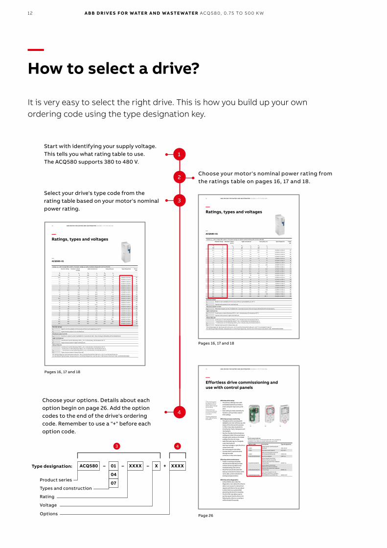
Select your drive's type code from the rating table based on your motor's nominal power rating.
Choose your motor's nominal power rating fromthe ratings table on pages 16, 17 and 18.
Start with identifying your supply voltage. This tells you what rating table to use. The ACQ580 supports 380 to 480 V.
3 4
Type designation:
Product series
Types and construction
Rating
Voltage
Options
ACQ580 XXXX XXXX+ 01 X–––
04
07
—How to select a drive?
It is very easy to select the right drive. This is how you build up your own ordering code using the type designation key.
2
3
1
Page 26
Choose your options. Details about each option begin on page 26. Add the option codes to the end of the drive's ordering code. Remember to use a "+" before each option code.
4
13
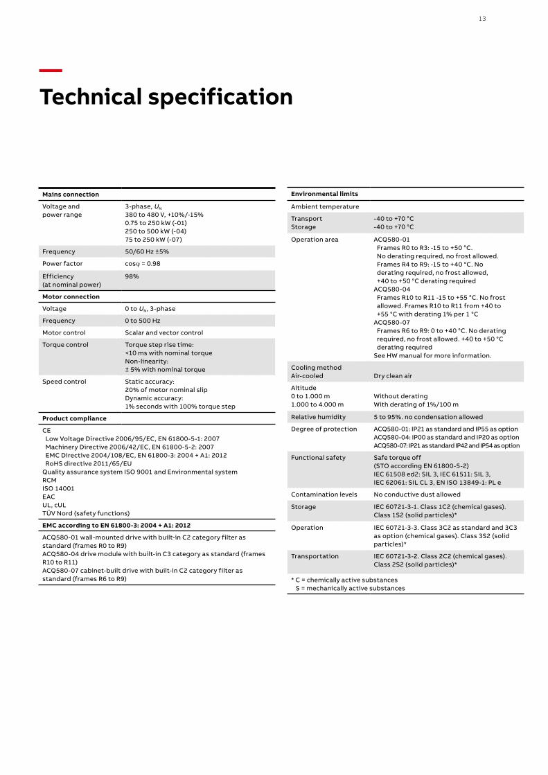
Mains connection
Voltage and power range
3-phase, UN 380 to 480 V, +10%/-15% 0.75 to 250 kW (-01)250 to 500 kW (-04)75 to 250 kW (-07)
Frequency 50/60 Hz ±5%
Power factor cosϕ = 0.98
Efficiency (at nominal power)
98%
Motor connection
Voltage 0 to UN, 3-phase
Frequency 0 to 500 Hz
Motor control Scalar and vector control
Torque control Torque step rise time:<10 ms with nominal torqueNon-linearity:± 5% with nominal torque
Speed control Static accuracy:20% of motor nominal slipDynamic accuracy:1% seconds with 100% torque step
Product compliance
CE Low Voltage Directive 2006/95/EC, EN 61800-5-1: 2007 Machinery Directive 2006/42/EC, EN 61800-5-2: 2007 EMC Directive 2004/108/EC, EN 61800-3: 2004 + A1: 2012 RoHS directive 2011/65/EUQuality assurance system ISO 9001 and Environmental system RCM ISO 14001EACUL, cUL TÜV Nord (safety functions)
EMC according to EN 61800-3: 2004 + A1: 2012
ACQ580-01 wall-mounted drive with built-in C2 category filter asstandard (frames R0 to R9)ACQ580-04 drive module with built-in C3 category as standard (frames R10 to R11)ACQ580-07 cabinet-built drive with built-in C2 category filter asstandard (frames R6 to R9)
Environmental limits
Ambient temperature
Transport Storage
-40 to +70 °C -40 to +70 °C
Operation area ACQ580-01 Frames R0 to R3: -15 to +50 °C. No derating required, no frost allowed. Frames R4 to R9: -15 to +40 °C. No derating required, no frost allowed, +40 to +50 °C derating requiredACQ580-04 Frames R10 to R11 -15 to +55 °C. No frost allowed. Frames R10 to R11 from +40 to +55 °C with derating 1% per 1 °CACQ580-07 Frames R6 to R9: 0 to +40 °C. No derating required, no frost allowed. +40 to +50 °C derating requiredSee HW manual for more information.
Cooling methodAir-cooled Dry clean air
Altitude0 to 1.000 m1.000 to 4.000 m
Without deratingWith derating of 1%/100 m
Relative humidity 5 to 95%. no condensation allowed
Degree of protection ACQ580-01: IP21 as standard and IP55 as optionACQ580-04: IP00 as standard and IP20 as optionACQ580-07: IP21 as standard IP42 and IP54 as option
Functional safety Safe torque off(STO according EN 61800-5-2)IEC 61508 ed2: SIL 3, IEC 61511: SIL 3,IEC 62061: SIL CL 3, EN ISO 13849-1: PL e
Contamination levels No conductive dust allowed
Storage IEC 60721-3-1. Class 1C2 (chemical gases).Class 1S2 (solid particles)*
Operation IEC 60721-3-3. Class 3C2 as standard and 3C3 as option (chemical gases). Class 3S2 (solid particles)*
Transportation IEC 60721-3-2. Class 2C2 (chemical gases). Class 2S2 (solid particles)*
* C = chemically active substances S = mechanically active substances
—Technical specification
14 A B B D R I V E S FO R WATE R A N D WA S TE WATE R ACQ5 8 0, 0 .75 TO 5 0 0 K W
—01
—02
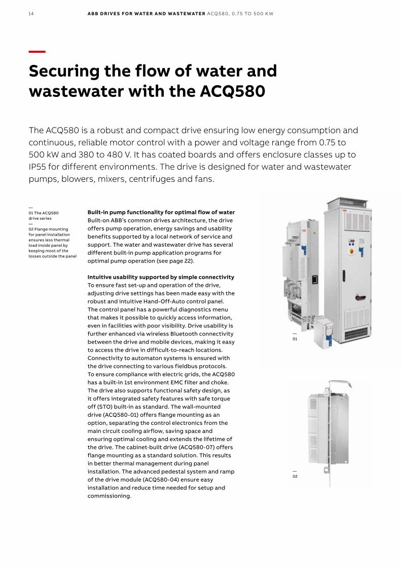
—Securing the flow of water and wastewater with the ACQ580
The ACQ580 is a robust and compact drive ensuring low energy consumption and continuous, reliable motor control with a power and voltage range from 0.75 to 500 kW and 380 to 480 V. It has coated boards and offers enclosure classes up to IP55 for different environments. The drive is designed for water and wastewater pumps, blowers, mixers, centrifuges and fans.
Built-in pump functionality for optimal flow of waterBuilt-on ABB’s common drives architecture, the drive offers pump operation, energy savings and usability benefits supported by a local network of service and support. The water and wastewater drive has several different built-in pump application programs for optimal pump operation (see page 22).
Intuitive usability supported by simple connectivityTo ensure fast set-up and operation of the drive, adjusting drive settings has been made easy with the robust and intuitive Hand-Off-Auto control panel. The control panel has a powerful diagnostics menu that makes it possible to quickly access information, even in facilities with poor visibility. Drive usability is further enhanced via wireless Bluetooth connectivity between the drive and mobile devices, making it easy to access the drive in difficult-to-reach locations. Connectivity to automaton systems is ensured with the drive connecting to various fieldbus protocols. To ensure compliance with electric grids, the ACQ580 has a built-in 1st environment EMC filter and choke. The drive also supports functional safety design, as it offers integrated safety features with safe torque off (STO) built-in as standard. The wall-mounted drive (ACQ580-01) offers flange mounting as an option, separating the control electronics from the main circuit cooling airflow, saving space and ensuring optimal cooling and extends the lifetime of the drive. The cabinet-built drive (ACQ580-07) offers flange mounting as a standard solution. This results in better thermal management during panel installation. The advanced pedestal system and ramp of the drive module (ACQ580-04) ensure easy installation and reduce time needed for setup and commissioning.
—01 The ACQ580 drive series—02 Flange mounting for panel installation ensures less thermal load inside panel by keeping most of the losses outside the panel
15
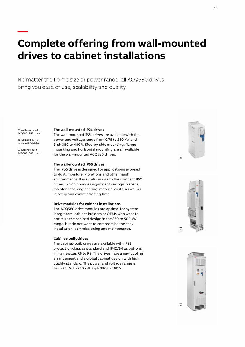
—Complete offering from wall-mounted drives to cabinet installations
No matter the frame size or power range, all ACQ580 drives bring you ease of use, scalability and quality.
The wall-mounted IP21 drivesThe wall-mounted IP21 drives are available with the power and voltage range from 0.75 to 250 kW and 3-ph 380 to 480 V. Side-by-side mounting, flange mounting and horizontal mounting are all available for the wall-mounted ACQ580 drives. The wall-mounted IP55 drivesThe IP55 drive is designed for applications exposed to dust, moisture, vibrations and other harsh environments. It is similar in size to the compact IP21 drives, which provides significant savings in space, maintenance, engineering, material costs, as well as in setup and commissioning time.
Drive modules for cabinet installationsThe ACQ580 drive modules are optimal for system integrators, cabinet builders or OEMs who want to optimize the cabined design in the 250 to 500 kW range, but do not want to compromise the easy installation, commissioning and maintenance.
Cabinet-built drivesThe cabinet-built drives are available with IP21 protection class as standard and IP42/54 as options in frame sizes R6 to R9. The drives have a new cooling arrangement and a global cabinet design with high quality standard. The power and voltage range is from 75 kW to 250 kW, 3-ph 380 to 480 V.
—01 Wall-mountedACQ580 IP55 drive— 02 ACQ580 Drive module IP00 drive— 03 Cabinet-built ACQ580 IP42 drive
—01
—02
—03
—ACQ580-01
16 A B B D R I V E S FO R WATE R A N D WA S TE WATE R ACQ5 8 0, 0 .75 TO 5 0 0 K W
—Ratings, types and voltages
Nominal ratings
IN Rated current available continuously without overloadability at 40 °C.
PN Typical motor power in no-overload use.
Maximum output current
Imax Maximum output current. Available for 2 seconds at start, then as long as allowed by drive temperature.
Light-overload use
ILd Continuous current allowing 110% ILd for 1 minute every 10 minutes at 40 °C.
PLd Typical motor power in light-overload use.
Heavy-duty use
IHd
Continuous current allowing 150% IHd for 1 minute every 10 minutes at 40 °C.* Continuous current allowing 130% IHd for 1 minute every 10 minutes at 40 °C.** Continuous current allowing 125% IHd for 1 minute every 10 minutes at 40 °C.
PHd Typical motor power in heavy-duty use.
The ratings apply for the frames R0 to R3 up to +50 °C and the frames R4 to R9 up to +40 °C in enclosed IP class 21For derating at high altitudes, temperatures or switching frequencies, see the user‘s HW manual, document code: 3AXD50000035866.
3-phase, UN = 400 V (range 380 to 480 V). The power ratings are valid at nominal voltage 400 V (0.75 to 250 kW)
Nominal ratings
Maximum output current
Light-overload use
Heavy-duty use Type designation Frame size
PN IN Imax PLd ILd PHd IHd
kW A A kW A kW A
0.75 2.6 3.2 0.75 2.5 0.55 1.8 ACQ580-01-02A6-4 R0
1.1 3.3 4.7 1.1 3.1 0.75 2.6 ACQ580-01-03A3-4 R0
1.5 4 5.9 1.5 3.8 1.1 3.3 ACQ580-01-04A0-4 R0
2.2 5.6 7.2 2.2 5.3 1.5 4 ACQ580-01-05A6-4 R0
3 7.2 10.1 3 6.8 2.2 5.6 ACQ580-01-07A2-4 R1
4 9.4 13 4 8.9 3 7.2 ACQ580-01-09A4-4 R1
5.5 12.6 14.1 5.5 12 4 9.4 ACQ580-01-12A6-4 R1
7.5 17 22.7 7.5 16.2 5.5 12.6 ACQ580-01-017A-4 R2
11 25 30.6 11 23.8 7.5 17 ACQ580-01-025A-4 R2
15 32 44.3 15 30.4 11 24.6 ACQ580-01-032A-4 R3
18.5 38 56.9 18.5 36.1 15 31.6 ACQ580-01-038A-4 R3
22 45 67.9 22 42.8 18.5 37.7 ACQ580-01-045A-4 R3
30 62 76 30 58 22 44.6 ACQ580-01-062A-4 R4
37 73 104 37 68.4 30 61 ACQ580-01-073A-4 R4
45 88 122 45 83 37 72 ACQ580-01-088A-4 R5
55 106 148 55 100 45 87 ACQ580-01-106A-4 R5
75 145 178 75 138 55 105 ACQ580-01-145A-4 R6
90 169 247 90 161 75 145 ACQ580-01-169A-4 R7
110 206 287 110 196 90 169 ACQ580-01-206A-4 R7
132 246 350 132 234 110 206 ACQ580-01-246A-4 R8
160 293 418 160 278 132 246 * ACQ580-01-293A-4 R8
200 363 498 200 345 160 293 ACQ580-01-363A-4 R9
250 430 545 200 400 200 363 ** ACQ580-01-430A-4 R9
17
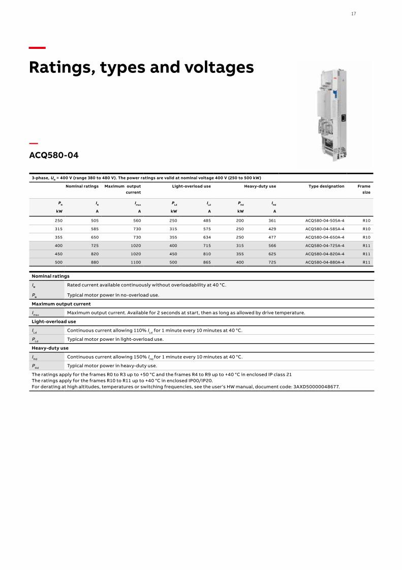
—Ratings, types and voltages
—ACQ580-04
Nominal ratings
IN Rated current available continuously without overloadability at 40 °C.
PN Typical motor power in no-overload use.
Maximum output current
Imax Maximum output current. Available for 2 seconds at start, then as long as allowed by drive temperature.
Light-overload use
ILd Continuous current allowing 110% ILd for 1 minute every 10 minutes at 40 °C.
PLd Typical motor power in light-overload use.
Heavy-duty use
IHd Continuous current allowing 150% IHd for 1 minute every 10 minutes at 40 °C.
PHd Typical motor power in heavy-duty use.
The ratings apply for the frames R0 to R3 up to +50 °C and the frames R4 to R9 up to +40 °C in enclosed IP class 21The ratings apply for the frames R10 to R11 up to +40 °C in enclosed IP00/IP20.For derating at high altitudes, temperatures or switching frequencies, see the user‘s HW manual, document code: 3AXD50000048677.
3-phase, UN = 400 V (range 380 to 480 V). The power ratings are valid at nominal voltage 400 V (250 to 500 kW)
Nominal ratings
Maximum output current
Light-overload use
Heavy-duty use Type designation Frame size
PN IN Imax PLd ILd PHd IHd
kW A A kW A kW A
250 505 560 250 485 200 361 ACQ580-04-505A-4 R10
315 585 730 315 575 250 429 ACQ580-04-585A-4 R10
355 650 730 355 634 250 477 ACQ580-04-650A-4 R10
400 725 1020 400 715 315 566 ACQ580-04-725A-4 R11
450 820 1020 450 810 355 625 ACQ580-04-820A-4 R11
500 880 1100 500 865 400 725 ACQ580-04-880A-4 R11
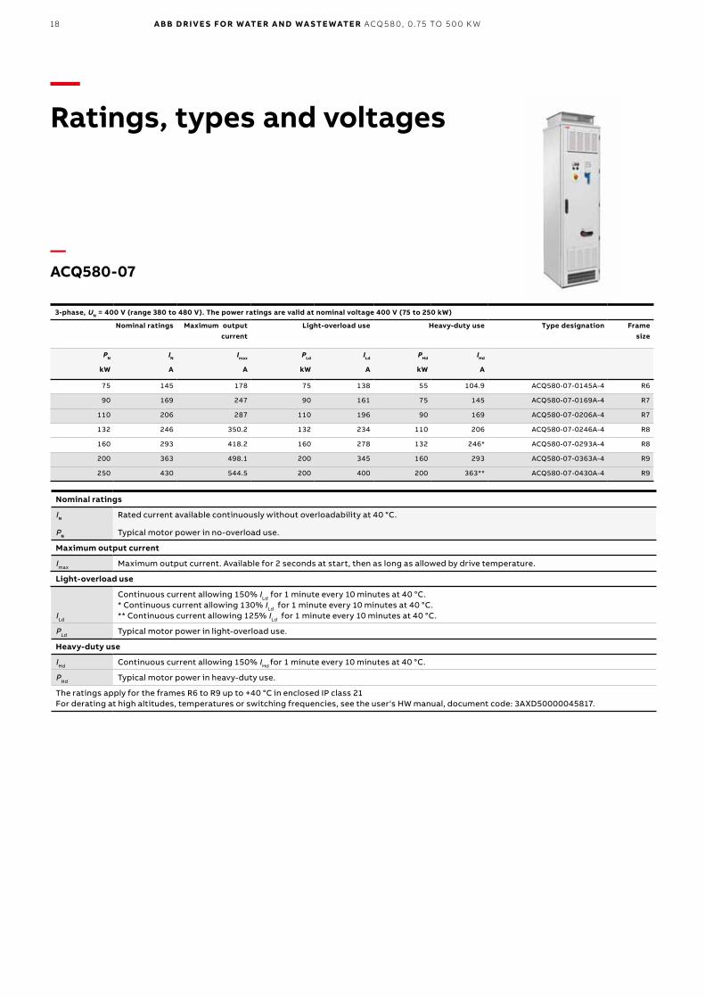
18 A B B D R I V E S FO R WATE R A N D WA S TE WATE R ACQ5 8 0, 0 .75 TO 5 0 0 K W
Nominal ratings
IN Rated current available continuously without overloadability at 40 °C.
PN Typical motor power in no-overload use.
Maximum output current
Imax Maximum output current. Available for 2 seconds at start, then as long as allowed by drive temperature.
Light-overload use
ILd
Continuous current allowing 150% ILd for 1 minute every 10 minutes at 40 °C.* Continuous current allowing 130% ILd for 1 minute every 10 minutes at 40 °C.** Continuous current allowing 125% ILd for 1 minute every 10 minutes at 40 °C.
PLd Typical motor power in light-overload use.
Heavy-duty use
IHd Continuous current allowing 150% IHd for 1 minute every 10 minutes at 40 °C.
PHd Typical motor power in heavy-duty use.
The ratings apply for the frames R6 to R9 up to +40 °C in enclosed IP class 21For derating at high altitudes, temperatures or switching frequencies, see the user‘s HW manual, document code: 3AXD50000045817.
—ACQ580-07
3-phase, UN = 400 V (range 380 to 480 V). The power ratings are valid at nominal voltage 400 V (75 to 250 kW)
Nominal ratings
Maximum output current
Light-overload use
Heavy-duty use Type designation Frame size
PN IN Imax PLd ILd PHd IHd
kW A A kW A kW A
75 145 178 75 138 55 104.9 ACQ580-07-0145A-4 R6
90 169 247 90 161 75 145 ACQ580-07-0169A-4 R7
110 206 287 110 196 90 169 ACQ580-07-0206A-4 R7
132 246 350.2 132 234 110 206 ACQ580-07-0246A-4 R8
160 293 418.2 160 278 132 246* ACQ580-07-0293A-4 R8
200 363 498.1 200 345 160 293 ACQ580-07-0363A-4 R9
250 430 544.5 200 400 200 363** ACQ580-07-0430A-4 R9
—Ratings, types and voltages
19
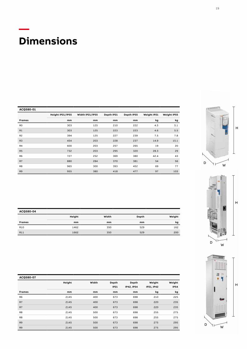
WD
H
ACQ580-01
Frames
Height IP21/IP55 Width IP21/IP55 Depth IP21 Depth IP55 Weight IP21 Weight IP55
mm mm mm mm kg kg
R0 303 125 210 222 4.5 5.1
R1 303 125 223 223 4.6 5.5
R2 394 125 227 239 7.5 7.8
R3 454 203 228 237 14.9 15.1
R4 600 203 257 265 19 20
R5 732 203 295 320 28.3 29
R6 727 252 369 380 42.4 43
R7 880 284 370 381 54 56
R8 965 300 393 452 69 77
R9 955 380 418 477 97 103
ACQ580-04
Frames
Height Width Depth Weight
mm mm mm kg
R10 1462 350 529 162
R11 1662 350 529 200
ACQ580-07
Frames
Height Width Depth
IP21
Depth
IP42, IP54
Weight
IP21, IP42
Weight
IP54
mm mm mm mm kg kg
R6 2145 400 673 698 210 225
R7 2145 400 673 698 220 235
R7 2145 400 673 698 220 235
R8 2145 500 673 698 255 275
R8 2145 500 673 698 255 275
R9 2145 500 673 698 275 295
R9 2145 500 673 698 275 295
—Dimensions
WD
H
WD
H
20 A B B D R I V E S FO R WATE R A N D WA S TE WATE R ACQ5 8 0, 0 .75 TO 5 0 0 K W
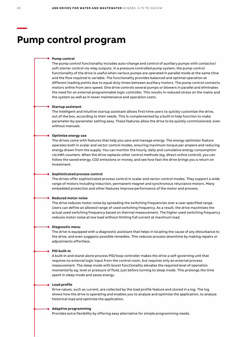
—Pump control program
Pump control The pump control functionality includes auto-change and control of auxiliary pumps with contactor/soft starter control via relay outputs. In a pressure controlled pump system, the pump control functionality of the drive is useful when various pumps are operated in parallel mode at the same time and the flow required is variable. The functionality provides balanced and optimal operation at different loading points due to equal duty times between auxiliary motors. The pump control connects motors online from zero speed. One drive controls several pumps or blowers in parallel and eliminates the need for an external programmable logic controller. This results in reduced stress on the mains and the system as well as in lower maintenance and operation costs.
Startup assistant The intelligent and intuitive startup assistant allows first-time users to quickly customize the drive, out of the box, according to their needs. This is complemented by a built-in help function to make parameter-by-parameter setting easy. These features allow the drive to be quickly commissioned, even without manuals.
Optimize energy useThe drives come with features that help you save and manage energy. The energy optimizer feature operates both in scalar and vector control modes, ensuring maximum torque per ampere and reducing energy drawn from the supply. You can monitor the hourly, daily and cumulative energy consumption via kWh counters. When the drive replaces other control methods (eg, direct-online control), you can follow the saved energy, CO2 emissions or money, and see how fast the drive brings you a return on investment.
Sophisticated process controlThe drives offer sophisticated process control in scalar and vector control modes. They support a wide range of motors including induction, permanent magnet and synchronous reluctance motors. Many embedded protection and other features improve performance of the motor and process.
Reduced motor noiseThe drive reduces motor noise by spreading the switching frequencies over a user-specified range. Users can define an allowed range of used switching frequency. As a result, the drive maximizes the actual used switching frequency based on thermal measurement. The higher used switching frequency reduces motor noise at low load without limiting full current at maximum load.
Diagnostic menuThe drive is equipped with a diagnostic assistant that helps in locating the cause of any disturbance to the drive, and even suggests possible remedies. This reduces process downtime by making repairs or adjustments effortless.
PID built-inA built-in and stand-alone process PID/loop controller makes the drive a self-governing unit that requires no external logic input from the control room, but requires only an external process measurement. The sleep mode with boost functionality elevates the required level of operation momentarily eg, level or pressure of fluid, just before turning to sleep mode. This prolongs the time spent in sleep mode and saves energy.
Load profileDrive values, such as current, are collected by the load profile feature and stored in a log. The log shows how the drive is operating and enables you to analyze and optimize the application, to analyze historical load and optimize the application.
Adaptive programmingProvides extra flexibility by offering easy alternative for simple programming needs.
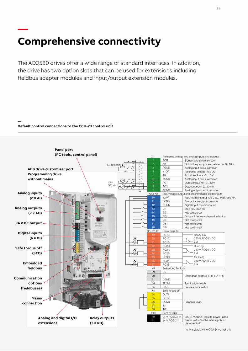
Analog inputs (2 × AI)
Analog outputs (2 × AO)
24 V DC output
Digital inputs (6 × DI)
Safe torque off (STO)
Embedded fieldbus
Communication options
(fieldbuses)
Mains connection
Relay outputs (3 × RO)
Panel port (PC tools, control panel)
ABB drive customizer portProgramming drive without mains
Analog and digital I/O extensions
max.500 ohm
1…10 kohmSignal cable shield (screen)Output frequency/speed reference: 0...10 VAnalog input circuit commonReference voltage 10 V DCActual feedback: 0...10 VAnalog input circuit commonOutput frequency: 0...10 VOutput current: 0...20 mAAnalog output circuit common
Aux. voltage output +24 V DC, max. 250 mAAux. voltage output commonDigital input common for allStop (0) / Start (1)Not configured Constant frequency/speed selectionNot configuredNot configuredNot configured
Ready run250 V AC/30 V DC2 ARunning250 V AC/30 V DC 2 AFault (-1)250 V AC/30 V DC2 A
Embedded fieldbus, EFB (EIA-485)
Termination switchBias resistors switch
Safe torque off.
Ext. 24 V AC/DC input to power up thecontrol unit when the main supply isdisconnected *
* only available in the CCU-24 control unit
X1 123456789
X2 & X3101112131415161718
X6, X7, X8192021222324252627X5293031S4S5X43435363738
X104041
Reference voltage and analog inputs and outputsSCRAI1AGND+10VAI2AGNDAO1AO2AGNDAux. voltage output and programmable digital inputs+24VDGNDDCOMDI1DI2DI3DI4DI5DI6Relay outputsRO1CRO1ARO1BRO2CRO2ARO2BRO3CRO3ARO3BEmbedded fieldbusB+A-DGNDTERMBIASSafe torque offOUT1OUT2SGNDIN1IN224 V AC/DC24 V AC/DC+ in24 V AC/DC- in
21
—Comprehensive connectivity
The ACQ580 drives offer a wide range of standard interfaces. In addition, the drive has two option slots that can be used for extensions including fieldbus adapter modules and input/output extension modules.
—Default control connections to the CCU-23 control unit
22 A B B D R I V E S FO R WATE R A N D WA S TE WATE R ACQ5 8 0, 0 .75 TO 5 0 0 K W
—Built-in pump application softwareThe built-in pump application software in the ACQ580 drives is designed to enhance the reliability and durability of the water and wastewater application in which it is used. The functions protect the pump and secure its optimal functionality, increasing cost efficiency. The built-in functionalities also support the user in securing the flow of the water and wastewater in the pump solution.
Multi-pump functionalityThis built-in functionality ensures continuous operation for multipump systems if one or more pumps fails or requires maintenance. The function maintains stable process conditions for several parallell pumps (up to 8 pumps at the same time) operating together. It is possible to optimize the speed and number of pumps needed when the required flow or pressure rate is variable.
Sensorless flow calculation Ensure the appropriate amount of water flowing without the need for external sensors. This will enable you to reduce costs as there is no need for setting up and using additional sensors or back up the flow meters to avoid interruptions in the process.
Level controlControl the filling or emptying of wastewater storage and water tower tanks. Level control can be used within a station controlling up to eight pumps. The level control function has varying pre-set water levels and the pumps will start and stop based on measured level. This method allows the pumps to run at an efficicent speed and ensures the pump sump does not become over contaminated by sediment.
Soft pipe fill The soft pipe fill function manages the pressure of water filling the pipeline with a gentle approach. This helps to avoid sudden pressure peaks and reduces the risk of water hammer which can cause damage to the water pipes.
Quick-rampProtect bearings when a submersible pump is started without water. Quick ramp allows your pump to reach optimal speed to extend pump life, ensure operation and prevent unplanned outages.
Pump cleaningKeeps the impeller of the pump clean by running a sequence of aggressive ramps between minimum and maximum pump speed.
Turbidity reductionWhen a pump starts as slow as possible, it creates the lowest turbidity values for the water being moved or extracted. When you combine the quick ramps and soft pipe fill functions, the drive will adjust the second acceleration rate to the best value possible based on your application needs.
Pump protectionThe built-in protection functionalities ensures that pumps can operate at the best possible conditions. The maximum pressure protections help to protect the pump and the system in case of a blockage in the pipeline. In case of a pipe rupture, the minimum pressure protection can generate an alarm or fault or can be programmed to run at certain speed to avoid dirty water entering the pipeline. The inlet pressure protection can help to avoid cavitation. When the inlet pressure of a water pump falls below pump design specifications, tiny vapor bubbles form. These bubbles collapse when they meet the impeller, causing shock waves and points of high temperature that can corrode the surface of the impeller.
Dry run protectionThis function prevents the pump from running dry. The water pump shaft and impeller are rotating at fast ratesand if there is no water in the system, the energy is releasedas heat. This will damage the pump over time, limiting itslifetime.
23
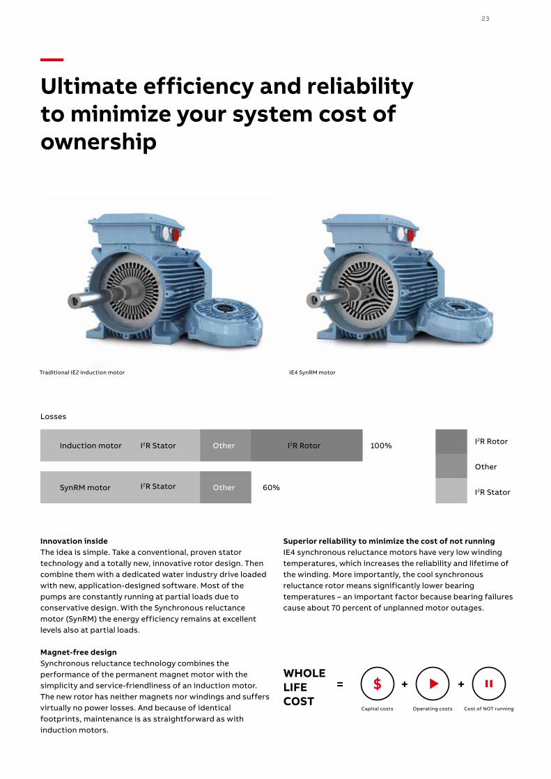
—Ultimate efficiency and reliability to minimize your system cost of ownership
Traditional IE2 induction motor IE4 SynRM motor
100%I2R RotorI2R StatorInduction motor Other I2R Rotor
Other
I2R Stator60%I2R StatorSynRM motor Other
Losses
Innovation insideThe idea is simple. Take a conventional, proven statortechnology and a totally new, innovative rotor design. Thencombine them with a dedicated water industry drive loadedwith new, application-designed software. Most of the pumps are constantly running at partial loads due to conservative design. With the Synchronous reluctance motor (SynRM) the energy efficiency remains at excellent levels also at partial loads.
Magnet-free designSynchronous reluctance technology combines the performance of the permanent magnet motor with the simplicity and service-friendliness of an induction motor. The new rotor has neither magnets nor windings and suffers virtually no power losses. And because of identical footprints, maintenance is as straightforward as with induction motors.
Superior reliability to minimize the cost of not running IE4 synchronous reluctance motors have very low winding temperatures, which increases the reliability and lifetime of the winding. More importantly, the cool synchronous reluctance rotor means significantly lower bearing temperatures – an important factor because bearing failures cause about 70 percent of unplanned motor outages.
Capital costs Operating costs Cost of NOT running
WHOLE LIFE COST
= + +$
24 A B B D R I V E S FO R WATE R A N D WA S TE WATE R ACQ5 8 0, 0 .75 TO 5 0 0 K W
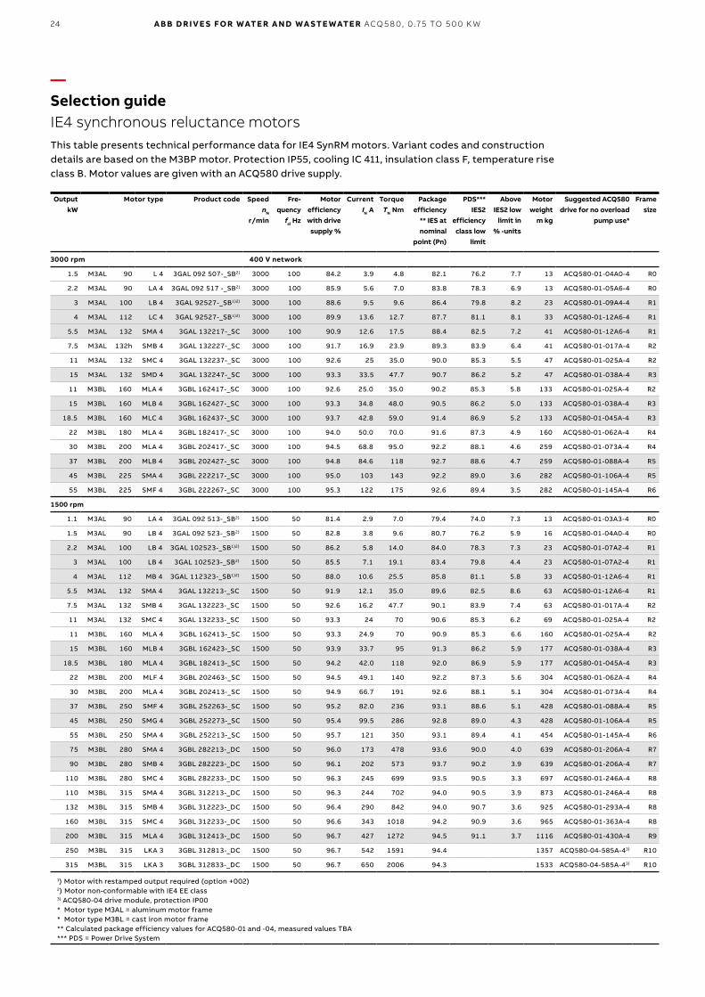
—Selection guideIE4 synchronous reluctance motors
OutputkW
Motor type Product code SpeednN
r/min
Fre-quency
fel Hz
Motor efficiencywith drive supply %
CurrentIN A
TorqueTN Nm
Package efficiency
** IES at nominal
point (Pn)
PDS*** IES2
efficiency class low
limit
Above IES2 low
limit in % -units
Motor weight
m kg
Suggested ACQ580 drive for no overload
pump use*
Frame size
3000 rpm 400 V network
1.5 M3AL 90 L 4 3GAL 092 507-_SB2) 3000 100 84.2 3.9 4.8 82.1 76.2 7.7 13 ACQ580-01-04A0-4 R0
2.2 M3AL 90 LA 4 3GAL 092 517 -_SB2) 3000 100 85.9 5.6 7.0 83.8 78.3 6.9 13 ACQ580-01-05A6-4 R0
3 M3AL 100 LB 4 3GAL 92527-_SB1)2) 3000 100 88.6 9.5 9.6 86.4 79.8 8.2 23 ACQ580-01-09A4-4 R1
4 M3AL 112 LC 4 3GAL 92527-_SB1)2) 3000 100 89.9 13.6 12.7 87.7 81.1 8.1 33 ACQ580-01-12A6-4 R1
5.5 M3AL 132 SMA 4 3GAL 132217-_SC 3000 100 90.9 12.6 17.5 88.4 82.5 7.2 41 ACQ580-01-12A6-4 R1
7.5 M3AL 132h SMB 4 3GAL 132227-_SC 3000 100 91.7 16.9 23.9 89.3 83.9 6.4 41 ACQ580-01-017A-4 R2
11 M3AL 132 SMC 4 3GAL 132237-_SC 3000 100 92.6 25 35.0 90.0 85.3 5.5 47 ACQ580-01-025A-4 R2
15 M3AL 132 SMD 4 3GAL 132247-_SC 3000 100 93.3 33.5 47.7 90.7 86.2 5.2 47 ACQ580-01-038A-4 R3
11 M3BL 160 MLA 4 3GBL 162417-_SC 3000 100 92.6 25.0 35.0 90.2 85.3 5.8 133 ACQ580-01-025A-4 R2
15 M3BL 160 MLB 4 3GBL 162427-_SC 3000 100 93.3 34.8 48.0 90.5 86.2 5.0 133 ACQ580-01-038A-4 R3
18.5 M3BL 160 MLC 4 3GBL 162437-_SC 3000 100 93.7 42.8 59.0 91.4 86.9 5.2 133 ACQ580-01-045A-4 R3
22 M3BL 180 MLA 4 3GBL 182417-_SC 3000 100 94.0 50.0 70.0 91.6 87.3 4.9 160 ACQ580-01-062A-4 R4
30 M3BL 200 MLA 4 3GBL 202417-_SC 3000 100 94.5 68.8 95.0 92.2 88.1 4.6 259 ACQ580-01-073A-4 R4
37 M3BL 200 MLB 4 3GBL 202427-_SC 3000 100 94.8 84.6 118 92.7 88.6 4.7 259 ACQ580-01-088A-4 R5
45 M3BL 225 SMA 4 3GBL 222217-_SC 3000 100 95.0 103 143 92.2 89.0 3.6 282 ACQ580-01-106A-4 R5
55 M3BL 225 SMF 4 3GBL 222267-_SC 3000 100 95.3 122 175 92.6 89.4 3.5 282 ACQ580-01-145A-4 R6
1500 rpm
1.1 M3AL 90 LA 4 3GAL 092 513-_SB2) 1500 50 81.4 2.9 7.0 79.4 74.0 7.3 13 ACQ580-01-03A3-4 R0
1.5 M3AL 90 LB 4 3GAL 092 523-_SB2) 1500 50 82.8 3.8 9.6 80.7 76.2 5.9 16 ACQ580-01-04A0-4 R0
2.2 M3AL 100 LB 4 3GAL 102523-_SB1)2) 1500 50 86.2 5.8 14.0 84.0 78.3 7.3 23 ACQ580-01-07A2-4 R1
3 M3AL 100 LB 4 3GAL 102523-_SB2) 1500 50 85.5 7.1 19.1 83.4 79.8 4.4 23 ACQ580-01-07A2-4 R1
4 M3AL 112 MB 4 3GAL 112323-_SB1)2) 1500 50 88.0 10.6 25.5 85.8 81.1 5.8 33 ACQ580-01-12A6-4 R1
5.5 M3AL 132 SMA 4 3GAL 132213-_SC 1500 50 91.9 12.1 35.0 89.6 82.5 8.6 63 ACQ580-01-12A6-4 R1
7.5 M3AL 132 SMB 4 3GAL 132223-_SC 1500 50 92.6 16.2 47.7 90.1 83.9 7.4 63 ACQ580-01-017A-4 R2
11 M3AL 132 SMC 4 3GAL 132233-_SC 1500 50 93.3 24 70 90.6 85.3 6.2 69 ACQ580-01-025A-4 R2
11 M3BL 160 MLA 4 3GBL 162413-_SC 1500 50 93.3 24.9 70 90.9 85.3 6.6 160 ACQ580-01-025A-4 R2
15 M3BL 160 MLB 4 3GBL 162423-_SC 1500 50 93.9 33.7 95 91.3 86.2 5.9 177 ACQ580-01-038A-4 R3
18.5 M3BL 180 MLA 4 3GBL 182413-_SC 1500 50 94.2 42.0 118 92.0 86.9 5.9 177 ACQ580-01-045A-4 R3
22 M3BL 200 MLF 4 3GBL 202463-_SC 1500 50 94.5 49.1 140 92.2 87.3 5.6 304 ACQ580-01-062A-4 R4
30 M3BL 200 MLA 4 3GBL 202413-_SC 1500 50 94.9 66.7 191 92.6 88.1 5.1 304 ACQ580-01-073A-4 R4
37 M3BL 250 SMF 4 3GBL 252263-_SC 1500 50 95.2 82.0 236 93.1 88.6 5.1 428 ACQ580-01-088A-4 R5
45 M3BL 250 SMG 4 3GBL 252273-_SC 1500 50 95.4 99.5 286 92.8 89.0 4.3 428 ACQ580-01-106A-4 R5
55 M3BL 250 SMA 4 3GBL 252213-_SC 1500 50 95.7 121 350 93.1 89.4 4.1 454 ACQ580-01-145A-4 R6
75 M3BL 280 SMA 4 3GBL 282213-_DC 1500 50 96.0 173 478 93.6 90.0 4.0 639 ACQ580-01-206A-4 R7
90 M3BL 280 SMB 4 3GBL 282223-_DC 1500 50 96.1 202 573 93.7 90.2 3.9 639 ACQ580-01-206A-4 R7
110 M3BL 280 SMC 4 3GBL 282233-_DC 1500 50 96.3 245 699 93.5 90.5 3.3 697 ACQ580-01-246A-4 R8
110 M3BL 315 SMA 4 3GBL 312213-_DC 1500 50 96.3 244 702 94.0 90.5 3.9 873 ACQ580-01-246A-4 R8
132 M3BL 315 SMB 4 3GBL 312223-_DC 1500 50 96.4 290 842 94.0 90.7 3.6 925 ACQ580-01-293A-4 R8
160 M3BL 315 SMC 4 3GBL 312233-_DC 1500 50 96.6 343 1018 94.2 90.9 3.6 965 ACQ580-01-363A-4 R8
200 M3BL 315 MLA 4 3GBL 312413-_DC 1500 50 96.7 427 1272 94.5 91.1 3.7 1116 ACQ580-01-430A-4 R9
250 M3BL 315 LKA 3 3GBL 312813-_DC 1500 50 96.7 542 1591 94.4 1357 ACQ580-04-585A-43) R10
315 M3BL 315 LKA 3 3GBL 312833-_DC 1500 50 96.7 650 2006 94.3 1533 ACQ580-04-585A-43) R10
1) Motor with restamped output required (option +002)2) Motor non-conformable with IE4 EE class3) ACQ580-04 drive module, protection IP00* Motor type M3AL = aluminum motor frame* Motor type M3BL = cast iron motor frame** Calculated package efficiency values for ACQ580-01 and -04, measured values TBA*** PDS = Power Drive System
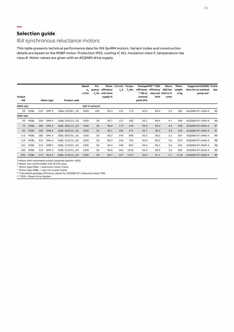
This table presents technical performance data for IE4 SynRM motors. Variant codes and construction details are based on the M3BP motor. Protection IP55, cooling IC 411, insulation class F, temperature rise class B. Motor values are given with an ACQ580 drive supply.
25
—Selection guideIE4 synchronous reluctance motors
OutputkW Motor type Product code
SpeednN
r/min
Fre-quency
fel Hz
Motor efficiencywith drive supply %
CurrentIN A
TorqueTN Nm
Package efficiency
** IES at nominal
point (Pn)
PDS*** IES2 efficiency class low
limit
Above IES2 low
limit in % -units
Motor weight
m kg
Suggested ACQ580 drive for no overload
pump use*
Frame size
3000 rpm 400 V network
55 M3BL 225 SMF 4 3GBL 222267-_SC 3000 100 95.3 122 175 92.6 89.4 3.5 282 ACQ580-07-145A-4 R6
1500 rpm
55 M3BL 250 SMA 4 3GBL 252213-_SC 1500 50 95.7 121 350 93.1 89.4 4.1 454 ACQ580-07-145A-4 R6
75 M3BL 280 SMA 4 3GBL 282213-_DC 1500 50 96.0 173 478 93.6 90.0 4.0 639 ACQ580-07-206A-4 R7
90 M3BL 280 SMB 4 3GBL 282223-_DC 1500 50 96.1 202 573 93.7 90.2 3.9 639 ACQ580-07-206A-4 R7
110 M3BL 280 SMC 4 3GBL 282233-_DC 1500 50 96.3 245 699 93.5 90.5 3.3 697 ACQ580-07-246A-4 R8
110 M3BL 315 SMA 4 3GBL 312213-_DC 1500 50 96.3 244 702 94.0 90.5 3.9 873 ACQ580-07-246A-4 R8
132 M3BL 315 SMB 4 3GBL 312223-_DC 1500 50 96.4 290 842 94.0 90.7 3.6 925 ACQ580-07-293A-4 R8
160 M3BL 315 SMC 4 3GBL 312233-_DC 1500 50 96.6 343 1018 94.2 90.9 3.6 965 ACQ580-07-363A-4 R8
200 M3BL 315 MLA 4 3GBL 312413-_DC 1500 50 96.7 427 1272 94.5 91.1 3.7 1116 ACQ580-07-430A-4 R9
1) Motor with restamped output required (option +002)2) Motor non-conformable with IE4 EE class* Motor type M3AL = aluminum motor frame* Motor type M3BL = cast iron motor frame** Calculated package efficiency values for ACQ580-07, measured values TBA*** PDS = Power Drive System
This table presents technical performance data for IE4 SynRM motors. Variant codes and construction details are based on the M3BP motor. Protection IP55, cooling IC 411, insulation class F, temperature rise class B. Motor values are given with an ACQ580 drive supply.
26 A B B D R I V E S FO R WATE R A N D WA S TE WATE R ACQ5 8 0, 0 .75 TO 5 0 0 K W
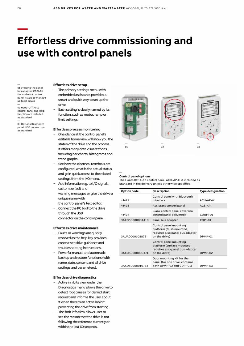
—Effortless drive commissioning and use with control panels
Option code Description Type designation
+J429Control panel with Bluetooth interface ACH-AP-W
+J425 Assistant control panel ACS-AP-I
+J424Blank control panel cover (no control panel delivered) CDUM-01
3AXD50000004419 Panel bus adapter CDPI-01
3AUA0000108878
Control panel mounting platform (flush mounted, requires also panel bus adapter on the drive) DPMP-01
3AXD50000009374
Control panel mounting platform (surface mounted, requires also panel bus adapter on the drive) DPMP-02
3AXD50000010763
Door mounting kit for the panel (for one drive, contains both DPMP-02 and CDPI-01) DPMP-EXT
—Control panel optionsThe Hand-Off-Auto control panel ACH-AP-H is included as standard in the delivery unless otherwise specified.
—03
—02
—01
Effortless drive setup − The primary settings menu with
embedded assistants provides a smart and quick way to set up the drive.
− Each setting is clearly named by its function, such as motor, ramp or limit settings.
Effortless process monitoring − One glance at the control panel's
editable home view will show you the status of the drive and the process. It offers many data visualizations including bar charts, histograms and trend graphs.
− See how the electrical terminals are configured, what is the actual status and gain quick access to the related settings from the I/O menu.
− Add information eg, to I/O signals, customize fault and warning messages or give the drive a unique name with the control panel’s text editor.
− Connect the PC tool to the drive through the USB connector on the control panel.
Effortless drive maintenance − Faults or warnings are quickly
resolved as the help key provides context sensitive guidance and troubleshooting instructions.
− Powerful manual and automatic backup and restore functions (with name, date, content and all drive settings and parameters).
Effortless drive diagnostics − Active inhibits view under the
Diagnostics menu allows the drive to detect root causes for denied start request and informs the user about it when there is an active inhibit preventing the drive from starting.
− The limit info view allows user to see the reason that the drive is not following the reference currently or within the last 60 seconds.
—01 By using the panel bus adapter, CDPI-01 the assistant control panel is able to manage up to 32 drives—02 Hand-Off-Auto control panel and Help function are includedas standard—03 Optional Bluetooth panel. USB connection as standard
27
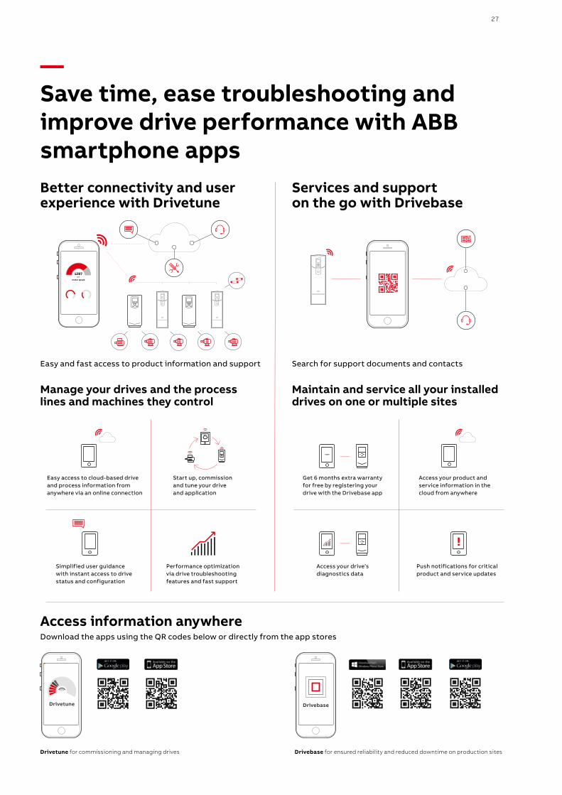
—Save time, ease troubleshooting and improve drive performance with ABB smartphone apps
Search for support documents and contactsEasy and fast access to product information and support
Better connectivity and user experience with Drivetune
Manage your drives and the process lines and machines they control
Maintain and service all your installed drives on one or multiple sites
Services and support on the go with Drivebase
Easy access to cloud-based drive and process information from anywhere via an online connection
Access your product and service information in the cloud from anywhere
Start up, commission and tune your drive and application
Simplified user guidance with instant access to drive status and configuration
Performance optimization via drive troubleshooting features and fast support
Access your drive’s diagnostics data
Get 6 months extra warranty for free by registering your drive with the Drivebase app
Push notifications for critical product and service updates
Download the apps using the QR codes below or directly from the app stores
Drivebase for ensured reliability and reduced downtime on production sitesDrivetune for commissioning and managing drives
Access information anywhere
28 A B B D R I V E S FO R WATE R A N D WA S TE WATE R ACQ5 8 0, 0 .75 TO 5 0 0 K W
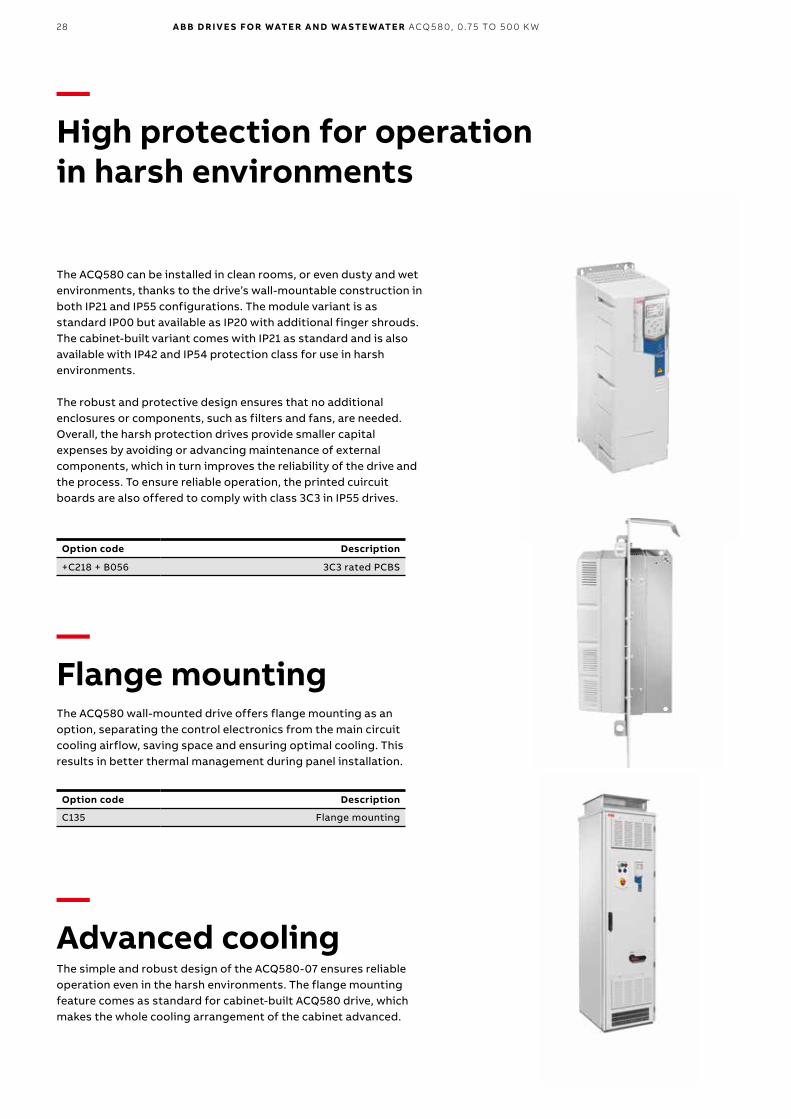
—High protection for operation in harsh environments
The ACQ580 can be installed in clean rooms, or even dusty and wet environments, thanks to the drive’s wall-mountable construction in both IP21 and IP55 configurations. The module variant is as standard IP00 but available as IP20 with additional finger shrouds. The cabinet-built variant comes with IP21 as standard and is also available with IP42 and IP54 protection class for use in harsh environments.
The robust and protective design ensures that no additional enclosures or components, such as filters and fans, are needed. Overall, the harsh protection drives provide smaller capital expenses by avoiding or advancing maintenance of external components, which in turn improves the reliability of the drive and the process. To ensure reliable operation, the printed cuircuit boards are also offered to comply with class 3C3 in IP55 drives.
—Flange mountingThe ACQ580 wall-mounted drive offers flange mounting as an option, separating the control electronics from the main circuit cooling airflow, saving space and ensuring optimal cooling. This results in better thermal management during panel installation.
—Advanced coolingThe simple and robust design of the ACQ580-07 ensures reliable operation even in the harsh environments. The flange mounting feature comes as standard for cabinet-built ACQ580 drive, which makes the whole cooling arrangement of the cabinet advanced.
Option code Description
C135 Flange mounting
Option code Description
+C218 + B056 3C3 rated PCBS
29
—Quick configuration for unpowered drives
Ordering code Description Type designation
3AXD50000019865 Cold configurator adapter, packed kit
CCA-01
—Cold configurator adapter
Ordering code Description Type designation
3AUA0000094517 2 x panel bus interface, 2 x 32 = max. 64 drives2 x Ethernet interface
SD memory cardUSB port for WLAN/3G
NETA-21
—Remote monitoring option
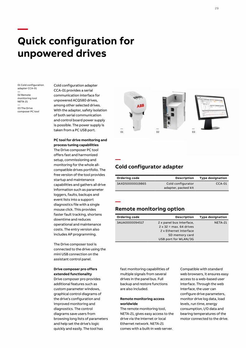
Cold configuration adapter CCA-01 provides a serial communication interface for unpowered ACQ580 drives, among other selected drives. With the adapter, safety isolation of both serial communication and control board power supply is possible. The power supply is taken from a PC USB port.
PC tool for drive monitoring and process tuning capabilitiesThe Drive composer PC tool offers fast and harmonized setup, commissioning and monitoring for the whole all-compatible drives portfolio. The free version of the tool provides startup and maintenance capabilities and gathers all drive information such as parameter loggers, faults, backups and event lists into a support diagnostics file with a single mouse click. This provides faster fault tracking, shortens downtime and reduces operational and maintenance costs. The entry version also includes AP programming.
The Drive composer tool is connected to the drive using the mini USB connection on the assistant control panel.
Drive composer pro offers extended functionalityDrive composer pro provides additional features such as custom parameter windows, graphical control diagrams of the drive’s configuration and improved monitoring and diagnostics. The control diagrams save users from browsing long lists of parameters and help set the drive’s logic quickly and easily. The tool has
—01
—02
01 Cold configuration adapter CCA-01—02 Remote monitoring tool NETA-21—03 The Drive composer PC tool
—03
fast monitoring capabilities of multiple signals from several drives in the panel bus. Full backup and restore functions are also included.
Remote monitoring access worldwideThe remote monitoring tool, NETA-21, gives easy access to the drive via the Internet or local Ethernet network. NETA-21 comes with a built-in web server.
Compatible with standard web browsers, it ensures easy access to a web-based user interface. Through the web interface, the user can configure drive parameters, monitor drive log data, load levels, run time, energy consumption, I/O data and bearing temperatures of the motor connected to the drive.
30 A B B D R I V E S FO R WATE R A N D WA S TE WATE R ACQ5 8 0, 0 .75 TO 5 0 0 K W
—Flexible connectivity to automation networks
Option code Fieldbus protocol Adapter
+K451 DeviceNet FDNA-01
+K454 PROFIBUS-DP FPBA-01
+K458 Modbus/RTU FSCA-01
+K473 Ethernet (EtherNet/IP™,
Modbus TCP, PROFINET)
FENA-11
+K475 2-port Ethernet (EtherNet/IP™,
Modbus TCP, PROFINET)
FENA-21
—Fieldbus adapters
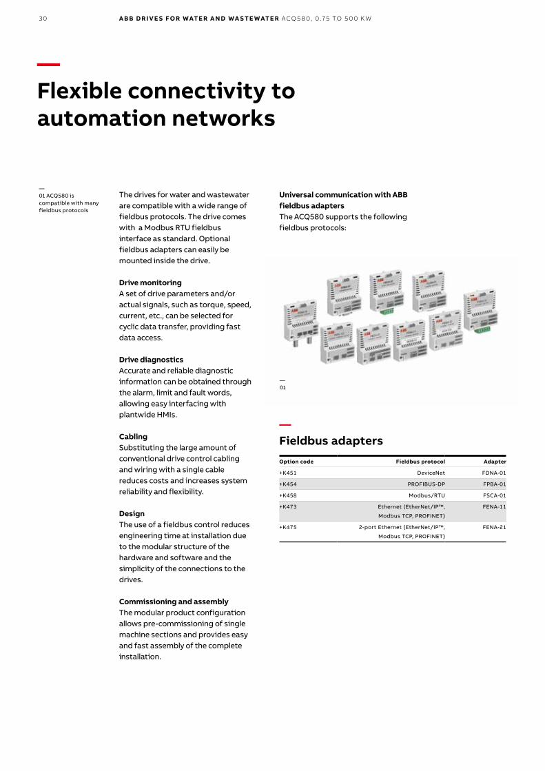
The drives for water and wastewater are compatible with a wide range of fieldbus protocols. The drive comes with a Modbus RTU fieldbus interface as standard. Optional fieldbus adapters can easily be mounted inside the drive.
Drive monitoringA set of drive parameters and/or actual signals, such as torque, speed, current, etc., can be selected for cyclic data transfer, providing fast data access.
Drive diagnosticsAccurate and reliable diagnostic information can be obtained through the alarm, limit and fault words, allowing easy interfacing with plantwide HMIs.
CablingSubstituting the large amount of conventional drive control cabling and wiring with a single cable reduces costs and increases system reliability and flexibility.
DesignThe use of a fieldbus control reduces engineering time at installation due to the modular structure of the hardware and software and the simplicity of the connections to the drives.
Commissioning and assemblyThe modular product configuration allows pre-commissioning of single machine sections and provides easy and fast assembly of the complete installation.
Universal communication with ABB fieldbus adaptersThe ACQ580 supports the following fieldbus protocols:
—01 ACQ580 is compatible with many fieldbus protocols
—01
31
—Input/output extension and thermistor protection modules for increased connectivity and safety
—Fieldbus adapters
Option code Description Type designation
+L501 External 24 V AC and DC 2 x RO and 1 x DO
CMOD-01
+L523 External 24 V and isolated PTC interface
CMOD-02
+L512 115/230 V digital input6 x DI and 2 x RO
CHDI-01
+L537 +Q971
ATEX certified PTC interface and
external 24V
CP TC- 0 2
—I/O options
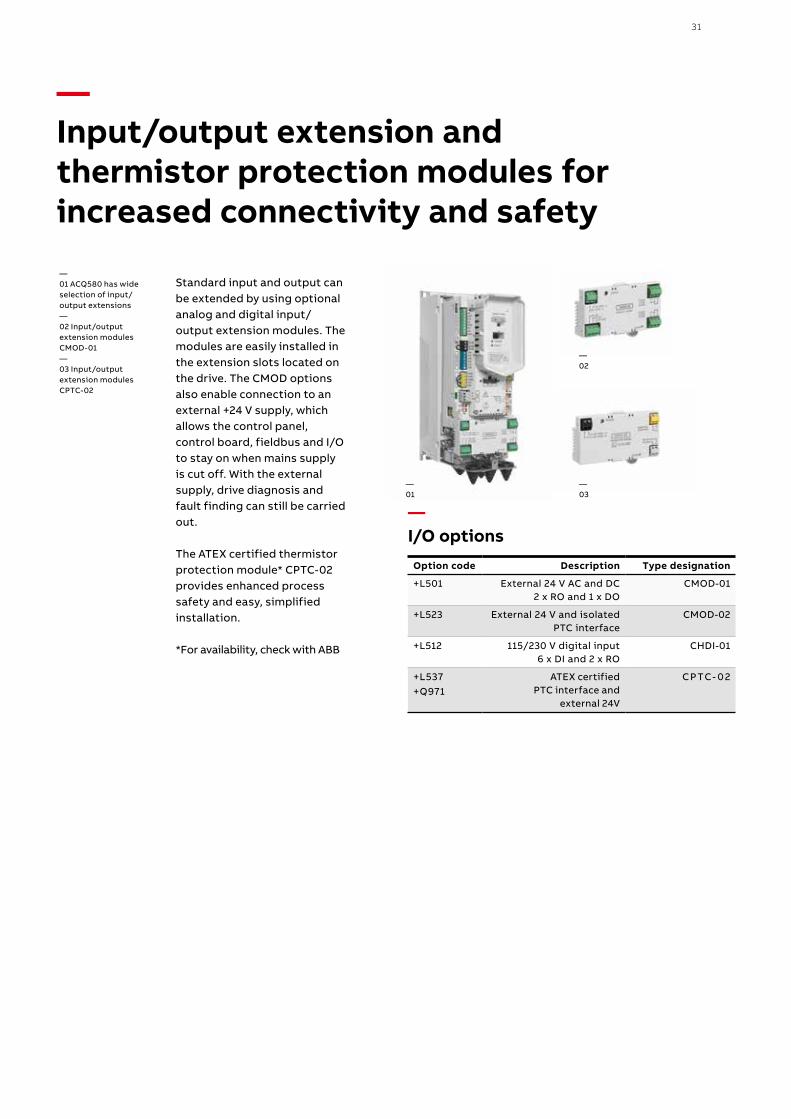
Standard input and output can be extended by using optional analog and digital input/output extension modules. The modules are easily installed in the extension slots located on the drive. The CMOD options also enable connection to an external +24 V supply, which allows the control panel, control board, fieldbus and I/O to stay on when mains supply is cut off. With the external supply, drive diagnosis and fault finding can still be carried out.
The ATEX certified thermistor protection module* CPTC-02 provides enhanced process safety and easy, simplified installation.
*For availability, check with ABB
—01 ACQ580 has wide selection of input/output extensions —02 Input/output extension modules CMOD-01—03 Input/output extension modules CPTC-02
—01
—02
—03
—EMC – electromagnetic compatibility
Comparison of EMC standards
EMC according to EN 61800-3product standard
EN 61800-3product
standard
EN 55011. product family standard for industrial,
scientific and medical (ISM)
equipment
EN 61000-6-4, generic emission standard for
industrial environments
EN 61000-6-3, genericemission standard for
residential, commercial and light-industrial
environment
1st environment. unrestricted distribution Category C1 Group 1. Class B Not applicable Applicable
1st environment. restricted distribution Category C2 Group 1. Class A Applicable Not applicable
2nd environment. unrestricted distribution Category C3 Group 2. Class A Not applicable Not applicable
2nd environment. restricted distribution Category C4 Not applicable Not applicable Not applicable
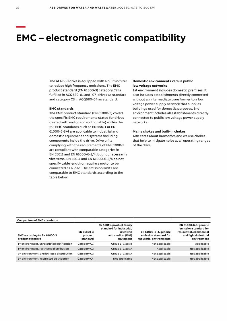
The ACQ580 drive is equipped with a built-in filter to reduce high frequency emissions. The EMC product standard (EN 61800-3) category C2 is fulfilled in ACQ580-01 and -07 drives as standard and category C3 in ACQ580-04 as standard.
EMC standards The EMC product standard (EN 61800-3) covers the specific EMC requirements stated for drives (tested with motor and motor cable) within the EU. EMC standards such as EN 55011 or EN 61000-6-3/4 are applicable to industrial and domestic equipment and systems including components inside the drive. Drive units complying with the requirements of EN 61800-3 are compliant with comparable categories in EN 55011 and EN 61000-6-3/4, but not necessarily vice versa. EN 55011 and EN 61000-6-3/4 do not specify cable length or require a motor to be connected as a load. The emission limits are comparable to EMC standards according to the table below.
Domestic environments versus public low voltage networks1st environment includes domestic premises. It also includes establishments directly connected without an intermediate transformer to a low voltage power supply network that supplies buildings used for domestic purposes. 2nd environment includes all establishments directly connected to public low voltage power supply networks.
Mains chokes and built-in chokesABB cares about harmonics and we use chokes that help to mitigate noise at all operating ranges of the drive.
32 A B B D R I V E S FO R WATE R A N D WA S TE WATE R ACQ5 8 0, 0 .75 TO 5 0 0 K W
33
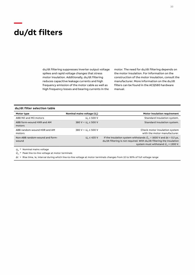
—du/dt filters
du/dt filtering suppresses inverter output voltage spikes and rapid voltage changes that stress motor insulation. Additionally, du/dt filtering reduces capacitive leakage currents and high frequency emission of the motor cable as well as high frequency losses and bearing currents in the
motor. The need for du/dt filtering depends on the motor insulation. For information on the construction of the motor insulation, consult the manufacturer. More information on the du/dt filters can be found in the ACQ580 hardware manual.
du/dt filter selection table
Motor type Nominal mains voltage (UN) Motor insulation requirement
ABB M2 and M3 motors UN ≤ 500 V Standard insulation system.
ABB form-wound HXR and AM motors
380 V < UN ≤ 500 V Standard insulation system.
ABB random-wound HXR and AM motors
380 V < UN ≤ 500 V Check motor insulation system with the motor manufacturer.
Non-ABB random-wound and form-wound
UN ≤ 420 V If the insulation system withstands ÛLL = 1600 V and Δt = 0.2 μs, du/dt filtering is not required. With du/dt filtering the insulation
system must withstand ÛLL = 1300 V.
UN = Nominal mains voltage
ÛLL = Peak line-to-line voltage at motor terminals
Δt = Rise time, ie, interval during which line-to-line voltage at motor terminals changes from 10 to 90% of full voltage range
34 A B B D R I V E S FO R WATE R A N D WA S TE WATE R ACQ5 8 0, 0 .75 TO 5 0 0 K W
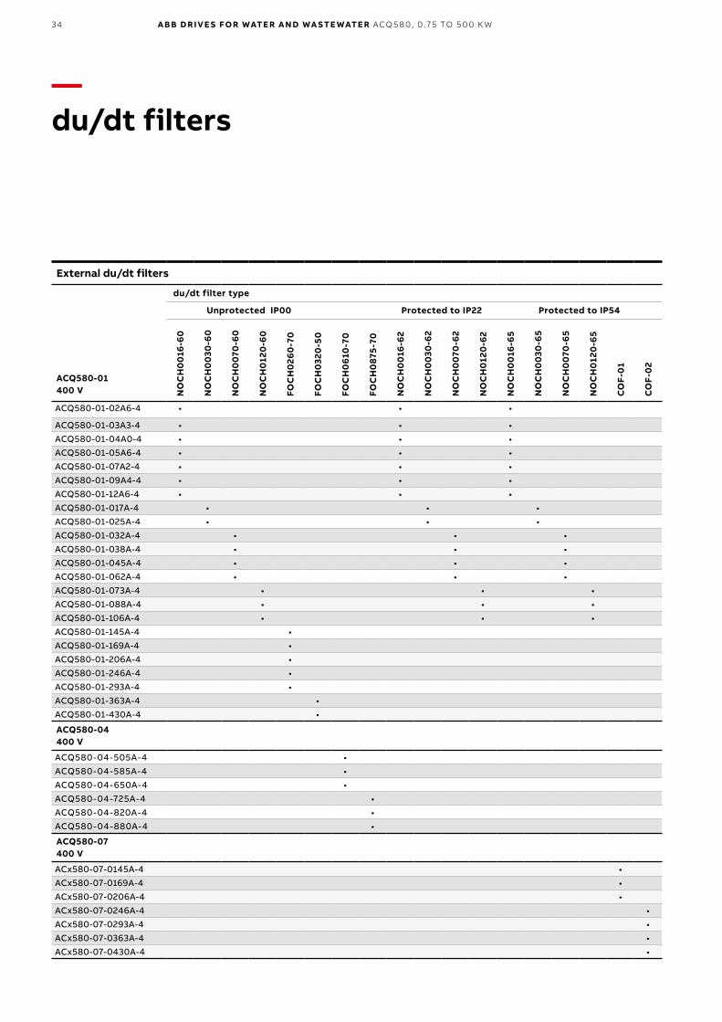
External du/dt filters
ACQ580-01400 V
du/dt filter type
Unprotected IP00 Protected to IP22 Protected to IP54
NO
CH
00
16-6
0
NO
CH
00
30-6
0
NO
CH
00
70-6
0
NO
CH
012
0-6
0
FOC
H0
260
-70
FOC
H0
320
-50
FOC
H0
610
-70
FOC
H0
875-
70
NO
CH
00
16-6
2
NO
CH
00
30-6
2
NO
CH
00
70-6
2
NO
CH
012
0-6
2
NO
CH
00
16-6
5
NO
CH
00
30-6
5
NO
CH
00
70-6
5
NO
CH
012
0-6
5
CO
F-0
1
CO
F-0
2
ACQ580-01-02A6-4 • • •
ACQ580-01-03A3-4 • • •ACQ580-01-04A0-4 • • •ACQ580-01-05A6-4 • • •ACQ580-01-07A2-4 • • •ACQ580-01-09A4-4 • • •ACQ580-01-12A6-4 • • •ACQ580-01-017A-4 • • •ACQ580-01-025A-4 • • •ACQ580-01-032A-4 • • •ACQ580-01-038A-4 • • •ACQ580-01-045A-4 • • •ACQ580-01-062A-4 • • •ACQ580-01-073A-4 • • •ACQ580-01-088A-4 • • •ACQ580-01-106A-4 • • •ACQ580-01-145A-4 •ACQ580-01-169A-4 •ACQ580-01-206A-4 •ACQ580-01-246A-4 •ACQ580-01-293A-4 •ACQ580-01-363A-4 •ACQ580-01-430A-4 •
ACQ580-04400 V
ACQ580-04-505A-4 •ACQ580-04-585A-4 •ACQ580-04-650A-4 •ACQ580-04-725A-4 •ACQ580-04-820A-4 •ACQ580-04-880A-4 •
ACQ580-07400 V
ACx580-07-0145A-4 •ACx580-07-0169A-4 •ACx580-07-0206A-4 •ACx580-07-0246A-4 •ACx580-07-0293A-4 •ACx580-07-0363A-4 •ACx580-07-0430A-4 •
—du/dt filters
35
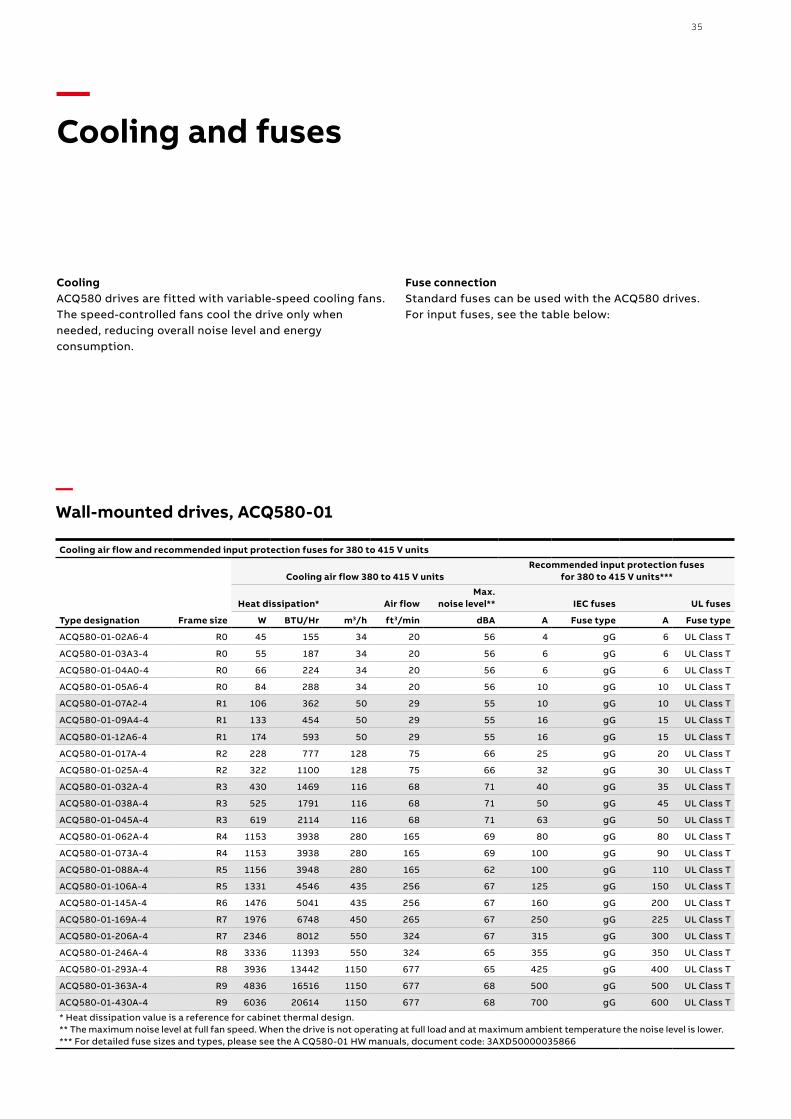
Cooling ACQ580 drives are fitted with variable-speed cooling fans. The speed-controlled fans cool the drive only when needed, reducing overall noise level and energy consumption.
Fuse connection Standard fuses can be used with the ACQ580 drives. For input fuses, see the table below:
—Cooling and fuses
Cooling air flow and recommended input protection fuses for 380 to 415 V units
Type designation Frame size
Cooling air flow 380 to 415 V unitsRecommended input protection fuses
for 380 to 415 V units***
Heat dissipation* Air flowMax.
noise level** IEC fuses UL fuses
W BTU/Hr m3/h ft3/min dBA A Fuse type A Fuse type
ACQ580-01-02A6-4 R0 45 155 34 20 56 4 gG 6 UL Class T
ACQ580-01-03A3-4 R0 55 187 34 20 56 6 gG 6 UL Class T
ACQ580-01-04A0-4 R0 66 224 34 20 56 6 gG 6 UL Class T
ACQ580-01-05A6-4 R0 84 288 34 20 56 10 gG 10 UL Class T
ACQ580-01-07A2-4 R1 106 362 50 29 55 10 gG 10 UL Class T
ACQ580-01-09A4-4 R1 133 454 50 29 55 16 gG 15 UL Class T
ACQ580-01-12A6-4 R1 174 593 50 29 55 16 gG 15 UL Class T
ACQ580-01-017A-4 R2 228 777 128 75 66 25 gG 20 UL Class T
ACQ580-01-025A-4 R2 322 1100 128 75 66 32 gG 30 UL Class T
ACQ580-01-032A-4 R3 430 1469 116 68 71 40 gG 35 UL Class T
ACQ580-01-038A-4 R3 525 1791 116 68 71 50 gG 45 UL Class T
ACQ580-01-045A-4 R3 619 2114 116 68 71 63 gG 50 UL Class T
ACQ580-01-062A-4 R4 1153 3938 280 165 69 80 gG 80 UL Class T
ACQ580-01-073A-4 R4 1153 3938 280 165 69 100 gG 90 UL Class T
ACQ580-01-088A-4 R5 1156 3948 280 165 62 100 gG 110 UL Class T
ACQ580-01-106A-4 R5 1331 4546 435 256 67 125 gG 150 UL Class T
ACQ580-01-145A-4 R6 1476 5041 435 256 67 160 gG 200 UL Class T
ACQ580-01-169A-4 R7 1976 6748 450 265 67 250 gG 225 UL Class T
ACQ580-01-206A-4 R7 2346 8012 550 324 67 315 gG 300 UL Class T
ACQ580-01-246A-4 R8 3336 11393 550 324 65 355 gG 350 UL Class T
ACQ580-01-293A-4 R8 3936 13442 1150 677 65 425 gG 400 UL Class T
ACQ580-01-363A-4 R9 4836 16516 1150 677 68 500 gG 500 UL Class T
ACQ580-01-430A-4 R9 6036 20614 1150 677 68 700 gG 600 UL Class T
* Heat dissipation value is a reference for cabinet thermal design.** The maximum noise level at full fan speed. When the drive is not operating at full load and at maximum ambient temperature the noise level is lower.*** For detailed fuse sizes and types, please see the A CQ580-01 HW manuals, document code: 3AXD50000035866
—Wall-mounted drives, ACQ580-01
36 A B B D R I V E S FO R WATE R A N D WA S TE WATE R ACQ5 8 0, 0 .75 TO 5 0 0 K W
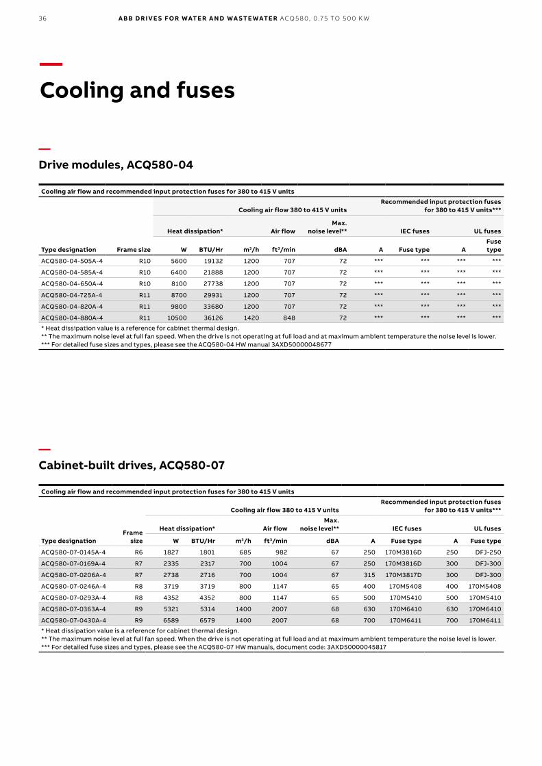
—Cooling and fuses
Cooling air flow and recommended input protection fuses for 380 to 415 V units
Type designationFrame
size
Cooling air flow 380 to 415 V unitsRecommended input protection fuses
for 380 to 415 V units***
Heat dissipation* Air flowMax.
noise level** IEC fuses UL fuses
W BTU/Hr m3/h ft3/min dBA A Fuse type A Fuse type
ACQ580-07-0145A-4 R6 1827 1801 685 982 67 250 170M3816D 250 DFJ-250
ACQ580-07-0169A-4 R7 2335 2317 700 1004 67 250 170M3816D 300 DFJ-300
ACQ580-07-0206A-4 R7 2738 2716 700 1004 67 315 170M3817D 300 DFJ-300
ACQ580-07-0246A-4 R8 3719 3719 800 1147 65 400 170M5408 400 170M5408
ACQ580-07-0293A-4 R8 4352 4352 800 1147 65 500 170M5410 500 170M5410
ACQ580-07-0363A-4 R9 5321 5314 1400 2007 68 630 170M6410 630 170M6410
ACQ580-07-0430A-4 R9 6589 6579 1400 2007 68 700 170M6411 700 170M6411
* Heat dissipation value is a reference for cabinet thermal design.** The maximum noise level at full fan speed. When the drive is not operating at full load and at maximum ambient temperature the noise level is lower.*** For detailed fuse sizes and types, please see the ACQ580-07 HW manuals, document code: 3AXD50000045817
Cooling air flow and recommended input protection fuses for 380 to 415 V units
Type designation Frame size
Cooling air flow 380 to 415 V unitsRecommended input protection fuses
for 380 to 415 V units***
Heat dissipation* Air flowMax.
noise level** IEC fuses UL fuses
W BTU/Hr m3/h ft3/min dBA A Fuse type AFuse type
ACQ580-04-505A-4 R10 5600 19132 1200 707 72 *** *** *** ***
ACQ580-04-585A-4 R10 6400 21888 1200 707 72 *** *** *** ***
ACQ580-04-650A-4 R10 8100 27738 1200 707 72 *** *** *** ***
ACQ580-04-725A-4 R11 8700 29931 1200 707 72 *** *** *** ***
ACQ580-04-820A-4 R11 9800 33680 1200 707 72 *** *** *** ***
ACQ580-04-880A-4 R11 10500 36126 1420 848 72 *** *** *** ***
* Heat dissipation value is a reference for cabinet thermal design.** The maximum noise level at full fan speed. When the drive is not operating at full load and at maximum ambient temperature the noise level is lower.*** For detailed fuse sizes and types, please see the ACQ580-04 HW manual 3AXD50000048677
—Drive modules, ACQ580-04
—Cabinet-built drives, ACQ580-07
37
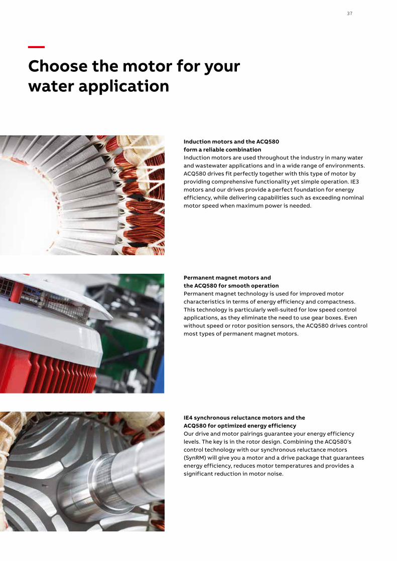
Induction motors and the ACQ580 form a reliable combinationInduction motors are used throughout the industry in many water and wastewater applications and in a wide range of environments. ACQ580 drives fit perfectly together with this type of motor by providing comprehensive functionality yet simple operation. IE3 motors and our drives provide a perfect foundation for energy efficiency, while delivering capabilities such as exceeding nominal motor speed when maximum power is needed.
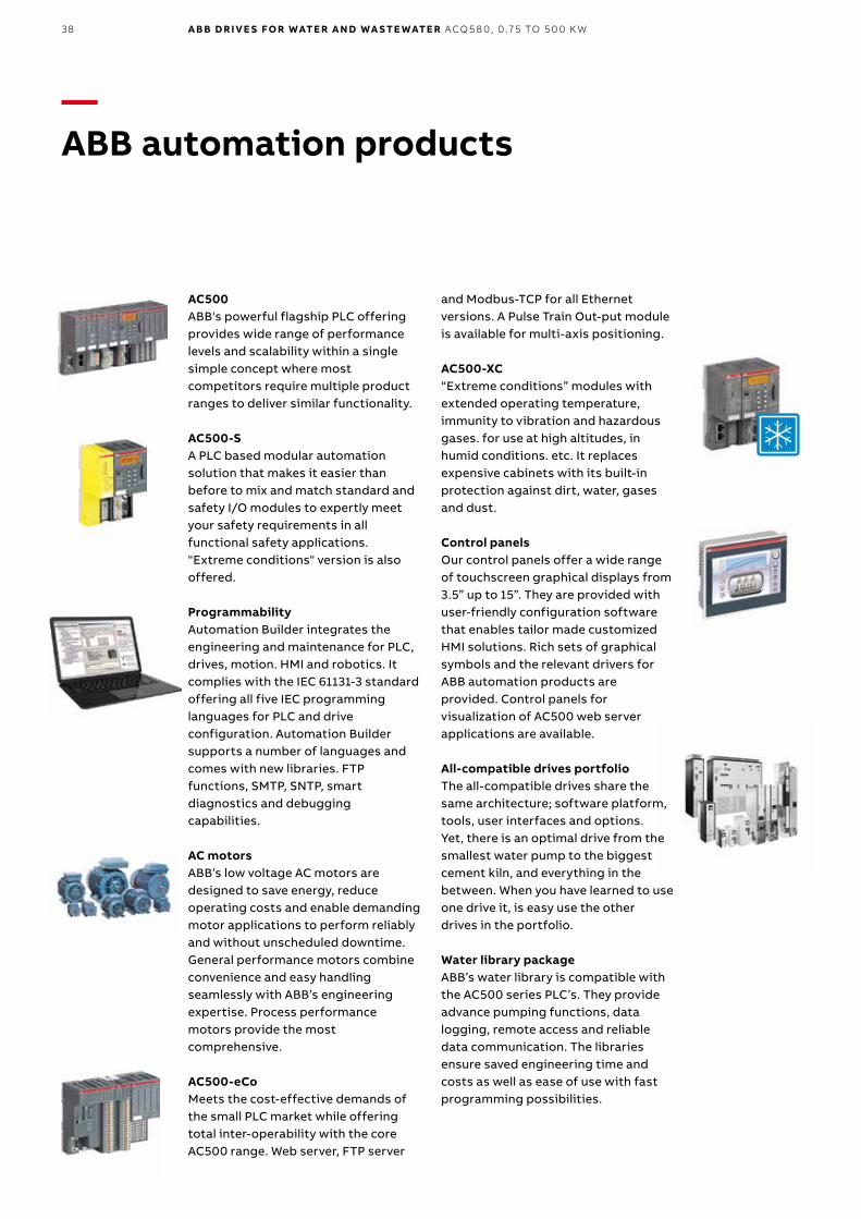
Permanent magnet motors and the ACQ580 for smooth operationPermanent magnet technology is used for improved motor characteristics in terms of energy efficiency and compactness. This technology is particularly well-suited for low speed control applications, as they eliminate the need to use gear boxes. Even without speed or rotor position sensors, the ACQ580 drives control most types of permanent magnet motors.
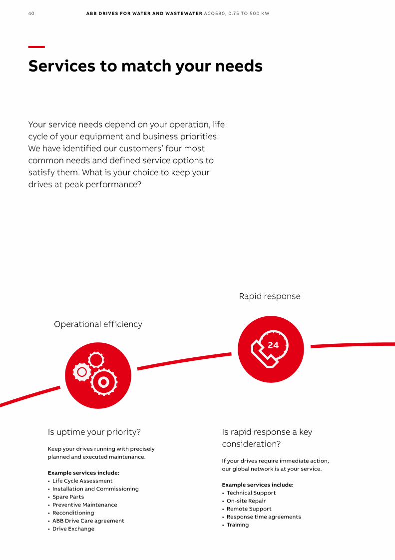
IE4 synchronous reluctance motors and the ACQ580 for optimized energy efficiencyOur drive and motor pairings guarantee your energy efficiency levels. The key is in the rotor design. Combining the ACQ580’s control technology with our synchronous reluctance motors (SynRM) will give you a motor and a drive package that guarantees energy efficiency, reduces motor temperatures and provides a significant reduction in motor noise.
—Choose the motor for your water application
38 A B B D R I V E S FO R WATE R A N D WA S TE WATE R ACQ5 8 0, 0 .75 TO 5 0 0 K W
AC500ABB's powerful flagship PLC offering provides wide range of performance levels and scalability within a single simple concept where most competitors require multiple product ranges to deliver similar functionality.
AC500-SA PLC based modular automation solution that makes it easier than before to mix and match standard and safety I/O modules to expertly meet your safety requirements in all functional safety applications. "Extreme conditions" version is also offered.
ProgrammabilityAutomation Builder integrates the engineering and maintenance for PLC, drives, motion. HMI and robotics. It complies with the IEC 61131-3 standard offering all five IEC programming languages for PLC and drive configuration. Automation Builder supports a number of languages and comes with new libraries. FTP functions, SMTP, SNTP, smart diagnostics and debugging capabilities.
AC motorsABB’s low voltage AC motors are designed to save energy, reduce operating costs and enable demanding motor applications to perform reliably and without unscheduled downtime. General performance motors combine convenience and easy handling seamlessly with ABB’s engineering expertise. Process performance motors provide the most comprehensive.
AC500-eCoMeets the cost-effective demands of the small PLC market while offering total inter-operability with the core AC500 range. Web server, FTP server
and Modbus-TCP for all Ethernet versions. A Pulse Train Out-put module is available for multi-axis positioning.
AC500-XC“Extreme conditions” modules with extended operating temperature, immunity to vibration and hazardous gases. for use at high altitudes, in humid conditions. etc. It replaces expensive cabinets with its built-in protection against dirt, water, gases and dust.
Control panelsOur control panels offer a wide range of touchscreen graphical displays from 3.5” up to 15”. They are provided with user-friendly configuration software that enables tailor made customized HMI solutions. Rich sets of graphical symbols and the relevant drivers for ABB automation products are provided. Control panels for visualization of AC500 web server applications are available.
All-compatible drives portfolioThe all-compatible drives share the same architecture; software platform, tools, user interfaces and options. Yet, there is an optimal drive from the smallest water pump to the biggest cement kiln, and everything in the between. When you have learned to use one drive it, is easy use the other drives in the portfolio.
Water library packageABB’s water library is compatible withthe AC500 series PLC’s. They provideadvance pumping functions, datalogging, remote access and reliabledata communication. The librariesensure saved engineering time andcosts as well as ease of use with fastprogramming possibilities.
—ABB automation products

39
40 A B B D R I V E S FO R WATE R A N D WA S TE WATE R ACQ5 8 0, 0 .75 TO 5 0 0 K W
—Services to match your needs
Your service needs depend on your operation, life cycle of your equipment and business priorities. We have identified our customers’ four most common needs and defined service options to satisfy them. What is your choice to keep your drives at peak performance?
Is uptime your priority?
Keep your drives running with precisely planned and executed maintenance. Example services include:• Life Cycle Assessment• Installation and Commissioning• Spare Parts• Preventive Maintenance• Reconditioning• ABB Drive Care agreement• Drive Exchange
Is rapid response a key consideration?
If your drives require immediate action, our global network is at your service. Example services include:• Technical Support• On-site Repair• Remote Support• Response time agreements• Training
Operational efficiency
Rapid response
41
Option code Description
+P932 ACQ580 extension of warranty to 60 months from delivery
The future of your drives depends on the service you choose. Whatever you choose, it should be a well-informed decision. No guesswork. We have the expertise and experience to help you find and implement the right service for your drive equipment. You can start by asking yourself these two critical questions:
• Why should my drive be serviced?• What would my optimal service options be?
From here, you have our guidance and full support along the course you take, throughout the entire lifetime of your drives.
Your choice, your business efficiencyABB Drive Care agreement lets you focus on your core business. A selection of predefined service options matching your needs provides optimal, more reliable performance, extended drive lifetime and improved cost control. So you can reduce the risk of unplanned downtime and find it easier to budget for maintenance.
We can help you more by knowing where you are!Register your drive at www.abb.com/drivereg for extended warranty options and other benefits.
—Drives serviceYour choice, your future
Need to extend your assets’ lifetime?
Maximize your drive’s lifetime with our services. Example services include:• Life Cycle Assessment• Upgrades, Retrofits and Modernization• Replacement, Disposal and Recycling
Is performance most critical to your operation?
Get optimal performance out of your machinery and systems. Example services include:• Advanced services• Engineering and Consulting• Inspection and Diagnostics• Upgrades, Retrofits and Modernization• Workshop Repair• Tailored services
Life cycle management
Performance improvement
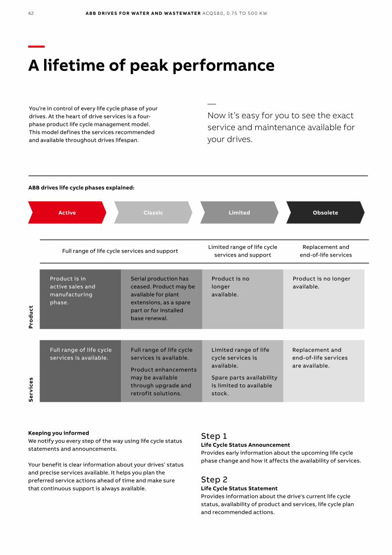
42 A B B D R I V E S FO R WATE R A N D WA S TE WATE R ACQ5 8 0, 0 .75 TO 5 0 0 K W
—A lifetime of peak performance
You’re in control of every life cycle phase of your drives. At the heart of drive services is a four-phase product life cycle management model. This model defines the services recommended and available throughout drives lifespan.
— Now it’s easy for you to see the exact service and maintenance available for your drives.
Product is in active sales and manufacturing phase.
Full range of life cycle services is available.
Full range of life cycle services is available.
Product enhancements may be available through upgrade and retrofit solutions.
Limited range of life cycle services is available.
Spare parts availability is limited to available stock.
Product is no longer available.
Product is no longer available.
ABB drives life cycle phases explained:
Full range of life cycle services and supportLimited range of life cycle
services and supportReplacement and
end-of-life services
Serial production has ceased. Product may be available for plant extensions, as a spare part or for installed base renewal.
Pro
du
ctS
ervi
ces
Replacement and end-of-life services are available.
Keeping you informedWe notify you every step of the way using life cycle status statements and announcements.
Your benefit is clear information about your drives’ status and precise services available. It helps you plan the preferred service actions ahead of time and make sure that continuous support is always available.
Step 1Life Cycle Status AnnouncementProvides early information about the upcoming life cycle phase change and how it affects the availability of services.
Step 2Life Cycle Status StatementProvides information about the drive's current life cycle status, availability of product and services, life cycle plan and recommended actions.
Active Classic Limited Obsolete

43
© Copyright 2017 ABB. All rights reserved. Specifications subject to change without notice. 3A
UA
00
00
194
172
RE
V C
EN
4.7
.20
17 *
2022
4
— For more information, please contact your local ABB representative or visit
www.abb.com/driveswww.abb.com/drivespartnerswww.abb.com/motors&generators
Online manuals for ACQ580 drive modules
Online manuals for wall-mounted ACQ580 drives
Online manuals for cabinet-built ACQ580 drives


![[XLS]specials.indiatoday.comspecials.indiatoday.com/aajtaknew/pdf/L92200DL1999PLC... · Web view1267748.75 0 0 0 0 0 0 0 0.75 0.75 0.75 0.75 0.75 0.75 0.75 0.75 0.75 0.75 12.75 0.75](https://img.pdfslide.us/doc/110x75/5aa92ca27f8b9a72188c8ae6/xls-view126774875-0-0-0-0-0-0-0-075-075-075-075-075-075-075-075-075.jpg)