Embed Size (px)
Citation preview
72 Warner Electric • 800-234-3369 P-1264-WE • 4/11
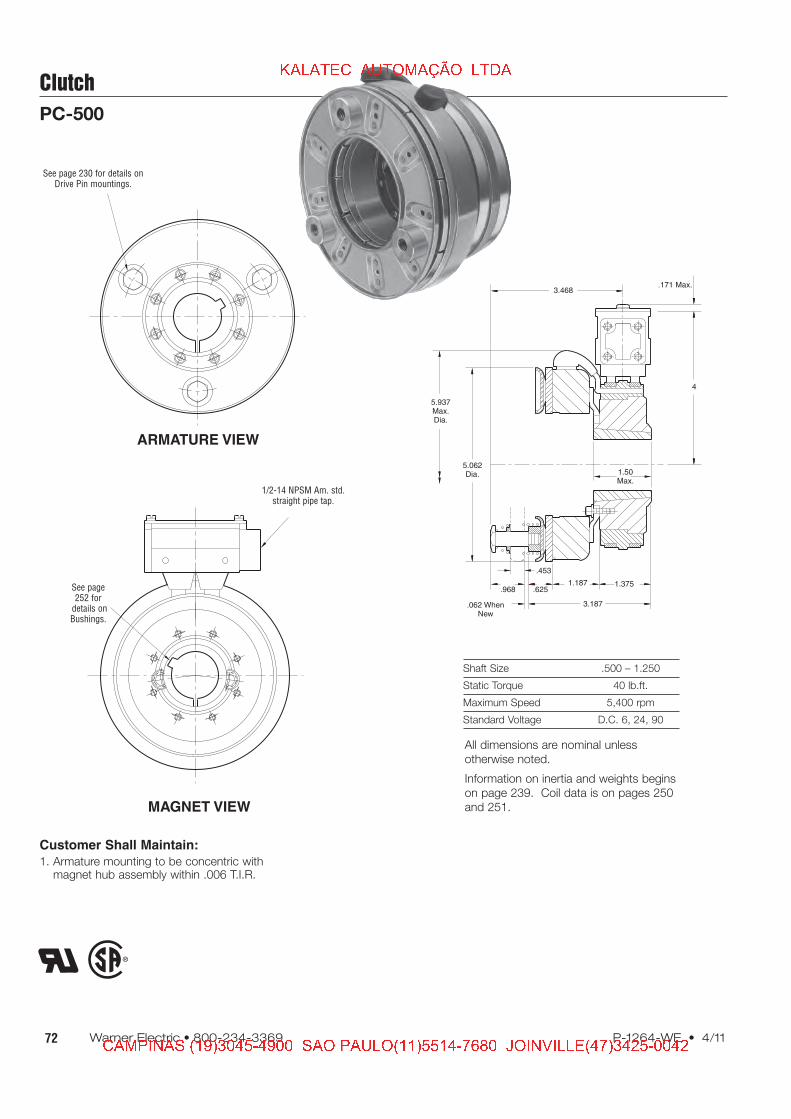
Shaft Size .500 – 1.250
Static Torque 40 lb.ft.
Maximum Speed 5,400 rpm
Standard Voltage D.C. 6, 24, 90
Clutch
PC-500
Customer Shall Maintain:
1. Armature mounting to be concentric withmagnet hub assembly within .006 T.I.R.
ARMATURE VIEW
MAGNET VIEW
.171 Max.
4
1.50Max.
.625.968
.062 WhenNew
5.937Max.Dia.
5.062Dia.
3.468
.453
1.187 1.375
3.187
See page 230 for details onDrive Pin mountings.
See page252 for
details onBushings.
1/2-14 NPSM Am. std.straight pipe tap.
All dimensions are nominal unless
otherwise noted.
Information on inertia and weights begins
on page 239. Coil data is on pages 250
and 251.
� � � � � � � � � � � � � � � � � �
� � � � � � � � � � � � � � � � � � � � � � � � � � � � � � � � � � � � � � � � � � � � � � � � � � � � � � � � � � � � �
73P-1264-WE • 4/11 Warner Electric • 800-234-3369
Clutch
PC-500
4
4-1
7
3
1-2
1-1
2-1
2
1(Shipped Assembled)
5
6
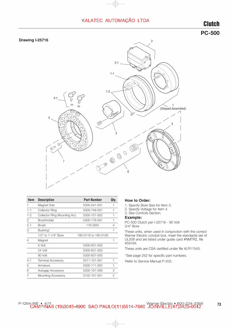
How to Order:
1. Specify Bore Size for Item 3.2. Specify Voltage for Item 4.3. See Controls Section.
Example:
PC-500 Clutch per I-25716 - 90 Volt3/4" Bore
These units, when used in conjunction with the correctWarner Electric conduit box, meet the standards set ofUL508 and are listed under guide card #NMTR2, file#59164.
These units are CSA certified under file #LR11543.
Item Description Part Number Qty.
1 Magnet Hub 5300-541-001 1
1-1 Collector Ring 5300-749-001 1
1-2 Collector Ring Mounting Acc. 5300-101-002 1
2 Brushholder 5300-178-001 1
2-1 Brush 176-0001 4
3 Bushing* 1
1/2" to 1-1/4" Bore 180-0116 to 180-0128
4 Magnet 1
6 Volt. 5300-631-002
24 Volt 5300-631-003
90 Volt 5300-631-005
4-1 Terminal Accessory 5311-101-001 1
5 Armature 5300-111-002 1
6 Autogap Accessory 5200-101-009 3
7 Mounting Accessory 5102-101-001 2
*See page 252 for specific part numbers.
Refer to Service Manual P-203.
Drawing I-25716
� � � � � � � � � � � � � � � � � �
� � � � � � � � � � � � � � � � � � � � � � � � � � � � � � � � � � � � � � � � � � � � � � � � � � � � � � � � � � � � �

74 Warner Electric • 800-234-3369 P-1264-WE • 4/11
Clutch
PC-825 Normal Duty
Shaft Size .500 – 1.625
Static Torque 125 lb.ft.
Maximum Speed 4,000 rpm
Standard Voltage D.C. 6, 24, 90
ARMATURE VIEW
COLLECTOR RING VIEW
.062
.171Max.
5.750
1.312
.093 when new
.562
Min. Running Clearance
2.562
9.437Max.Dia.
8.625Dia. 3.5625
Dia.
2.562Dia.
1.500
7.781Dia.
1.593
1.437
3.468 Max.
See page 230 for details onDrive Pin mountings.
See page 252 for detailson Bushings.
1/2-14 NPSM Am.std. straight pipe tap.
All dimensions are nominal unless
otherwise noted.
Information on inertia and weights begins
on page 239. Coil data is on pages 250
and 251.
� � � � � � � � � � � � � � � � � �
� � � � � � � � � � � � � � � � � � � � � � � � � � � � � � � � � � � � � � � � � � � � � � � � � � � � � � � � � � � � �
75P-1264-WE • 4/11 Warner Electric • 800-234-3369
Clutch
PC-825 Normal Duty
Drawing I-25562
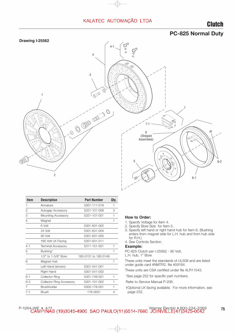
How to Order:
1. Specify Voltage for Item 4.2. Specify Bore Size for Item 5.3. Specify left hand or right hand hub for Item 6. (Bushing
enters from magnet side for L.H. hub and from hub sidefor R.H.)
4. See Controls Section.
Example:
PC-825 Clutch per I-25562 - 90 Volt,L.H. hub, 1" Bore
These units meet the standards of UL508 and are listedunder guide card #NMTR2, file #59164.
These units are CSA certified under file #LR11543.
1
3
4
4-1
2
6(Shipped
Assembled)
7-1
7
5
6-1
6-2
Item Description Part Number Qty.
1 Armature 5301-111-018 1
2 Autogap Accessory 5201-101-008 3
3 Mounting Accessory 5321-101-001 1
4 Magnet 1
6 Volt 5301-631-002
24 Volt 5301-631-004
90 Volt 5301-631-005
†90 Volt LK Facing 5301-631-011
4-1 Terminal Accessory 5311-101-001 1
5 Bushing* 1
1/2" to 1-5/8" Bore 180-0131 to 180-0149
6 Magnet Hub 1
Left Hand (shown) 5301-541-001
Right Hand 5301-541-002
6-1 Collector Ring 5301-749-001 1
6-2 Collector Ring Accessory 5301-101-002 1
7 Brushholder 5300-178-001 1
7-1 Brush 176-0001 4
*See page 252 for specific part numbers.
Refer to Service Manual P-206.
†Optional LK facing available. For more information, see
page 232.
� � � � � � � � � � � � � � � � � �
� � � � � � � � � � � � � � � � � � � � � � � � � � � � � � � � � � � � � � � � � � � � � � � � � � � � � � � � � � � � �

76 Warner Electric • 800-234-3369 P-1264-WE • 4/11
Clutch
PC-825 Heavy Duty
Shaft Size .500 – 1.625
Static Torque 125 lb.ft.
Maximum Speed 4,000 rpm
Standard Voltage D.C. 6, 24, 90
COLLECTOR RING VIEW
ARMATURE VIEW
Customer Shall Maintain:
1. Splined hub pilot diameter to be concentric with splinedarmature center of rotation within .010 T.I.R.
2. Magnet hub shaft to be concentric with splined armaturecenter of rotation within .006 T.I.R.
1.3431.593
5.750.093
.062
.171Max.
.125
.468 Max.
.531
1.312 1.437
.062
1/4-28 UNF-3A
Max. Length ofCustomer Pilot
(Left HandMagnet HubShown)
Min. RunningClearance
9.437Max.Dia.
8.625Dia.
2.3132.311PilotDia. 1.500
7.781Dia.
2.531
3.656 Max.
See page 252 for detailson Bushings.
1/2-14 NPSM Am. std. straight pipe tap.
.271/.263 Dia. (5) holes equallyspaced on 2.015 dia. Mounting holes
are within .003 of true positionrelative to pilot diameter.
1.640 dia.
All dimensions are nominal unless
otherwise noted.
Information on inertia and weights begins
on page 239. Coil data is on pages 250
and 251.
� � � � � � � � � � � � � � � � � �
� � � � � � � � � � � � � � � � � � � � � � � � � � � � � � � � � � � � � � � � � � � � � � � � � � � � � � � � � � � � �

77P-1264-WE • 4/11 Warner Electric • 800-234-3369
Drawing I-25563
How to Order:
1. Specify Voltage for Item 5.2. Specify Bore Size for Item 7.3. Specify left hand or right hand hub for Item 6.4. See Controls Section.
Example:
PC-825 Clutch per I-25563 - 90 Volt,L.H. hub, 1" Bore
These units meet the standards of UL508 and are listedunder guide card #NMTR2, file #59164. These units areCSA certified under file #LR11543
Clutch
PC-825 Heavy Duty1
(ShippedAssembled)
1-5
1-1
1-2
1-4
3
2
1-3
4
5
5-1
7
8-1
6-1
6-28
6(Shipped<
Assembled)
Item Description Part Number Qty.
1 Armature & Splined
Adapter Assembly 5321-111-001 1
1-1 Armature 5321-111-022 1
1-2 Splined Armature Adapter 104-0008 1
1-3 Autogap Accessory 5321-101-006 1
Autogap Spring 808-0054 1
Retainer Ring 748-0373 1
1-4 Button Head Screw 797-0272 3
1-5 Locknut 661-0004 3
2 Mounting Accessory 5201-101-001 1
3 Splined Hub 540-0146 1
4 Mounting Accessory 5321-101-001 1
5 Magnet 1
6 Volt 5301-631-002
24 Volt 5301-631-004
90 Volt 5301-631-005
†90 Volt LK Facing 5301-631-011
5-1 Terminal Accessory 5311-101-001 1
6 Magnet Hub Assembly 1
Right Hand 5301-541-002
Left Hand (shown) 5301-541-001
Item Description Part Number Qty.
6-1 Collector Ring 5301-749-001 1
6-2 Collector Ring Accessory 5301-101-002 1
7 Bushing, Taperlock* 180-0131 to 180-0149 1
8 Brushholder 5300-178-001 1
8-1 Brush 176-0001 4
*See page 252 for specific part numbers.
Refer to Service Manual P-206.
†Optional LK facing available. For more information, see
page 232.
� � � � � � � � � � � � � � � � � �
� � � � � � � � � � � � � � � � � � � � � � � � � � � � � � � � � � � � � � � � � � � � � � � � � � � � � � � � � � � � �

78 Warner Electric • 800-234-3369 P-1264-WE • 4/11
Clutch
PC-1000 Normal Duty
Shaft Size .500 – 2.500
Static Torque 240 lb.ft.
Maximum Speed 3,600 rpm
Standard Voltage D.C. 6, 24, 90
ARMATURE VIEW
COLLECTOR RING VIEW
See page 230 for details onDrive Pin mountings.
See page 252 for detailson Bushings.
1/2-14 NPSM Am. std.straight pipe tap.
.062
.171Max.
5.750
1.453
.093 When New
.562
Min. Running Clearance
2.937
11.093Max.Dia. 10.29
6 Dia. 5.252Dia.
4.125Dia.
1.750
7.781Dia.
1.906
1.750
3.906 Max.
All dimensions are nominal unless
otherwise noted.
Information on inertia and weights begins
on page 239. Coil data is on pages 250
and 251.
� � � � � � � � � � � � � � � � � �
� � � � � � � � � � � � � � � � � � � � � � � � � � � � � � � � � � � � � � � � � � � � � � � � � � � � � � � � � � � � �
79P-1264-WE • 4/11 Warner Electric • 800-234-3369
Clutch
PC-1000 Normal Duty
Drawing I-25582
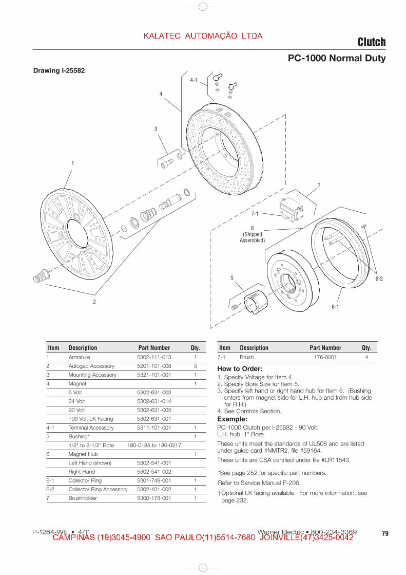
How to Order:
1. Specify Voltage for Item 4.2. Specify Bore Size for Item 5.3. Specify left hand or right hand hub for Item 6. (Bushing
enters from magnet side for L.H. hub and from hub sidefor R.H.)
4. See Controls Section.
Example:
PC-1000 Clutch per I-25582 - 90 Volt,L.H. hub, 1" Bore
These units meet the standards of UL508 and are listedunder guide card #NMTR2, file #59164.
These units are CSA certified under file #LR11543.
1
3
4
4-1
2
6(Shipped
Assembled)
7-1
7
5
6-1
6-2
Item Description Part Number Qty.
1 Armature 5302-111-013 1
2 Autogap Accessory 5201-101-008 3
3 Mounting Accessory 5321-101-001 1
4 Magnet 1
6 Volt 5302-631-003
24 Volt 5302-631-014
90 Volt 5302-631-005
†90 Volt LK Facing 5302-631-001
4-1 Terminal Accessory 5311-101-001 1
5 Bushing* 1
1/2" to 2-1/2" Bore 180-0185 to 180-0217
6 Magnet Hub 1
Left Hand (shown) 5302-541-001
Right Hand 5302-541-002
6-1 Collector Ring 5301-749-001 1
6-2 Collector Ring Accessory 5302-101-002 1
7 Brushholder 5300-178-001 1
Item Description Part Number Qty.
7-1 Brush 176-0001 4
*See page 252 for specific part numbers.
Refer to Service Manual P-206.
†Optional LK facing available. For more information, see
page 232.
� � � � � � � � � � � � � � � � � �
� � � � � � � � � � � � � � � � � � � � � � � � � � � � � � � � � � � � � � � � � � � � � � � � � � � � � � � � � � � � �
80 Warner Electric • 800-234-3369 P-1264-WE • 4/11
Clutch
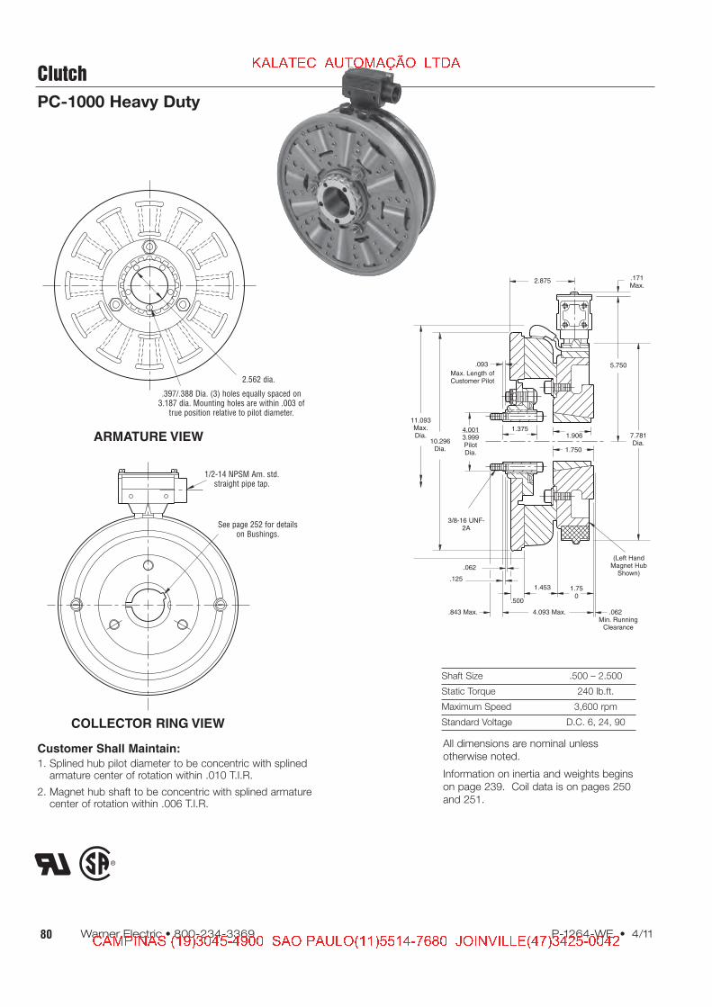
PC-1000 Heavy Duty
Shaft Size .500 – 2.500
Static Torque 240 lb.ft.
Maximum Speed 3,600 rpm
Standard Voltage D.C. 6, 24, 90COLLECTOR RING VIEW
ARMATURE VIEW
Customer Shall Maintain:
1. Splined hub pilot diameter to be concentric with splinedarmature center of rotation within .010 T.I.R.
2. Magnet hub shaft to be concentric with splined armaturecenter of rotation within .006 T.I.R.
See page 252 for detailson Bushings.
1/2-14 NPSM Am. std.straight pipe tap.
.397/.388 Dia. (3) holes equally spaced on3.187 dia. Mounting holes are within .003 of
true position relative to pilot diameter.
2.562 dia.
1.3751.906
5.750.093
.062
.171Max.
.125
.843 Max.
.500
1.453 1.750
.062
3/8-16 UNF-2A
Max. Length ofCustomer Pilot
(Left HandMagnet HubShown)
Min. RunningClearance
11.093Max.Dia.
10.296Dia.
4.0013.999PilotDia. 1.750
7.781Dia.
2.875
4.093 Max.
All dimensions are nominal unless
otherwise noted.
Information on inertia and weights begins
on page 239. Coil data is on pages 250
and 251.
� � � � � � � � � � � � � � � � � �
� � � � � � � � � � � � � � � � � � � � � � � � � � � � � � � � � � � � � � � � � � � � � � � � � � � � � � � � � � � � �

81P-1264-WE • 4/11 Warner Electric • 800-234-3369
Clutch
PC-1000 Heavy Duty
Drawing I-25583
How to Order:
1. Specify Voltage for Item 5.2. Specify Bore Size for Item 7.3. Specify left hand or right hand hub for Item 6.4. See Controls Section.
Example:
PC-1000 Clutch per I-25583 - 90 Volt,L.H. hub, 1" Bore
These units meet the standards of UL508 and are listed underguide card #NMTR2, file #59164.
These units are CSA certified under file #LR11543
1(Shipped
Assembled)
1-5
1-1
1-2
1-4
3
2
1-3
4
5
5-1
7
8-1
6-1
6-28
6(Shipped<
Assembled)
Item Description Part Number Qty.
1 Armature & Splined
Adapter Assembly 5322-111-002 1
1-1 Armature 5322-111-036 1
1-2 Splined Armature Adapter 104-0009 1
1-3 Autogap Accessory 5322-101-004 1
Autogap Spring 808-0061 1
Retainer Ring 748-0374 1
1-4 Button Head Screw 797-0272 3
1-5 Locknut 661-0004 3
2 Mounting Accessory 5202-101-001 1
3 Splined Hub 540-0147 1
4 Mounting Accessory 5321-101-001 1
5 Magnet 1
6 Volt 5302-631-003
24 Volt 5302-631-014
90 Volt 5302-631-005
†90 Volt LK Facing 5302-631-001
5-1 Terminal Accessory 5311-101-001 1
6 Magnet Hub Assembly 1
Right Hand 5302-541-002
Left Hand (shown) 5302-541-001
Item Description Part Number Qty.
6-1 Collector Ring 5301-749-001 1
6-2 Collector Ring Accessory 5302-101-002 1
7 Bushing, Taperlock* 180-0185 to 180-0217 1
8 Brushholder 5300-178-001 1
8-1 Brush 176-0001 4
*See page 252 for specific part numbers.
Refer to Service Manual P-206.
†Optional LK facing available. For more information, see
page 232.
� � � � � � � � � � � � � � � � � �
� � � � � � � � � � � � � � � � � � � � � � � � � � � � � � � � � � � � � � � � � � � � � � � � � � � � � � � � � � � � �

82 Warner Electric • 800-234-3369 P-1264-WE • 4/11
Clutch
PC-1225 Normal Duty
Shaft Size .937 – 3.000
Static Torque 465 lb.ft.
Maximum Speed 3,000 rpm
Standard Voltage D.C. 6, 24, 90
COLLECTOR RING VIEW
ARMATURE VIEW3
5.750
.171Max.
.093 When New
.062 Min.1.640.593
1/2-13 UNC-3B
RunningClearance
4.562 Max.
13.140Max.Dia.
12.625Dia.
5.877Dia.
4.625Dia.
3.500
7.781Dia.
3.156
See page 252 fordetails on Bushings.
1/2-14 NPSM Am. std.straight pipe tap.
See page 230 for details onDrive Pin mountings.
®
UL
All dimensions are nominal unless
otherwise noted.
Information on inertia and weights begins
on page 239. Coil data is on pages 250
and 251.
� � � � � � � � � � � � � � � � � �
� � � � � � � � � � � � � � � � � � � � � � � � � � � � � � � � � � � � � � � � � � � � � � � � � � � � � � � � � � � � �
83P-1264-WE • 4/11 Warner Electric • 800-234-3369
Clutch
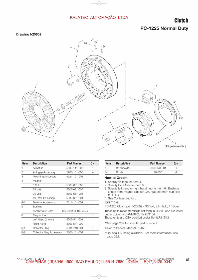
PC-1225 Normal Duty
Drawing I-25602
How to Order:
1. Specify Voltage for Item 4.2. Specify Bore Size for Item 5.3. Specify left hand or right hand hub for Item 6. (Bushing
enters from magnet side for L.H. hub and from hub sidefor R.H.)
4. See Controls Section.
Example:
PC-1225 Clutch per I-25602 - 90 Volt, L.H. hub, 1" Bore
These units meet standards set forth in UL508 and are listedunder guide card #NMTR2, file #59164.These units are CSA certified under file #LR11543
1
2
3
4
4-1
5
7-1
6-1
6-2
6(Shipped Assembled)
7
Item Description Part Number Qty.
1 Armature 5303-111-009 1
2 Autogap Accessory 5201-101-008 4
3 Mounting Accessory 5321-101-001 1
4 Magnet 1
6 Volt 5303-631-005
24 Volt 5303-631-007
90 Volt 5303-631-008
†90 Volt LK Facing 5303-631-001
4-1 Terminal Accessory 5311-101-001 1
5 Bushing* 1
15/16" to 3" Bore 180-0262 to 180-0295
6 Magnet Hub 1
Left Hand (shown) 5303-541-001
Right Hand 5303-541-002
6-1 Collector Ring 5301-749-001 1
6-2 Collector Ring Accessory 5303-101-004 1
Item Description Part Number Qty.
7 Brushholder 5300-178-001 1
7-1 Brush 176-0001 4
*See page 252 for specific part numbers.
Refer to Service Manual P-207.
†Optional LK facing available. For more information, see
page 232.
� � � � � � � � � � � � � � � � � �
� � � � � � � � � � � � � � � � � � � � � � � � � � � � � � � � � � � � � � � � � � � � � � � � � � � � � � � � � � � � �

84 Warner Electric • 800-234-3369 P-1264-WE • 4/11
Clutch
PC-1225 Heavy Duty
Shaft Size .937 – 3.000
Static Torque 465 lb.ft.
Maximum Speed 3,000 rpm
Standard Voltage D.C. 6, 24, 90
Customer Shall Maintain:
1. Splined hub pilot diameter to be concentricwith splined armature center of rotation within .010 T.I.R.
ARMATURE VIEW
COLLECTOR RING VIEW
1.500
4.3134.311
Pilot Dia.
5.750
.093
12.625
RunningDia. Max.
Max. Length ofCustomer Pilot
13.140
.171 Max.
.062
.125
.718 Max.
.062 Min.RunningClearance
3/8-16UNC-2A
(Left HandMagnet HubShown)
1.640 2.187
4.875 Max.
.562
3.156
7.781Dia.
3.00
3.468
.397/.388 Dia. (8) holes equally spaced on3.625 dia. Mounting holes are within .003 of
true position relative to pilot diameter.
See page 252 fordetails on Bushings.
1/2-14 NPSM Am. std. straight pipe tap.
All dimensions are nominal unless
otherwise noted.
Information on inertia and weights begins
on page 239. Coil data is on pages 250
and 251.
3.062 dia.
� � � � � � � � � � � � � � � � � �
� � � � � � � � � � � � � � � � � � � � � � � � � � � � � � � � � � � � � � � � � � � � � � � � � � � � � � � � � � � � �

85P-1264-WE • 4/11 Warner Electric • 800-234-3369
Clutch
PC-1225 Heavy Duty
Drawing I-25603
How to Order:
1. Specify Voltage for Item 5.2. Specify Bore Size for Item 7.3. Specify left hand or right hand hub for Item 6.4. See Controls Section.
Example:
PC-1225 Clutch perI-25603 - 90 Volt, L.H. hub, 1" Bore
These units meet the standards of UL508 and are listed underguide card #NMTR2, file #59164.These units are CSA certified under file #LR11543.
1(Shipped
Assembled)
1-5
3
2
1-1
1-2
1-3 5-1
4
5
7
8-1
8
6-1
6(Shipped<
Assembled)
6-2
1-4
Item Description Part Number Qty.
1 Armature & Splined
Adapter Assembly 5323-111-001 1
1-1 Armature 5323-111-034 1
1-2 Splined Armature Adapter 104-0010 1
1-3 Autogap Accessory 5323-101-002 1
Autogap Spring 808-0044 1
Retainer Ring 748-0370 1
1-4 Button Head Screw 797-0281 4
1-5 Locknut 661-0005 4
2 Mounting Accessory 5202-101-001 1
3 Splined Hub 540-0148 1
4 Mounting Accessory 5321-101-001 1
5 Magnet 1
6 Volt 5303-631-005
24 Volt 5303-631-007
90 Volt 5303-631-008
†90 Volt LK Facing 5303-631-001
5-1 Terminal Accessory 5311-101-001
6 Magnet Hub Assembly 1
Right Hand 5303-541-002
Left Hand (shown) 5303-541-001
Item Description Part Number Qty.
6-1 Collector Ring 5301-749-001 1
6-2 Collector Ring Accessory 5303-101-004 1
7 Bushing, Taperlock* 180-0262 to 180-0295 1
8 Brushholder 5300-178-001 1
8-1 Brush 176-0001 4
*See page 252 for specific part numbers.
Refer to Service Manual P-206.
†Optional LK facing available. For more information, see
page 232.
� � � � � � � � � � � � � � � � � �
� � � � � � � � � � � � � � � � � � � � � � � � � � � � � � � � � � � � � � � � � � � � � � � � � � � � � � � � � � � � �
86 Warner Electric • 800-234-3369 P-1264-WE • 4/11
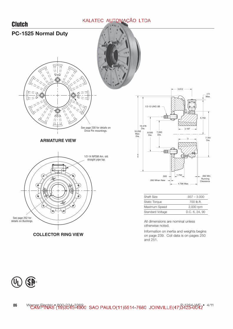
Clutch
PC-1525 Normal Duty
Shaft Size .937 – 3.000
Static Torque 700 lb.ft.
Maximum Speed 2,000 rpm
Standard Voltage D.C. 6, 24, 90
ARMATURE VIEW
COLLECTOR RING VIEW
See page 230 for details onDrive Pin mountings.
3
5.750
.171Max.
.093 When New
.062 Min.1.750.593
1/2-13 UNC-3B
RunningClearance
4.796 Max.
16.250Max.Dia.
15.578Dia.
8.500Dia.
7.093Dia.
3.812
7.781Dia.
3.187
See page 252 fordetails on Bushings.
1/2-14 NPSM Am. std.straight pipe tap.
®
UL
All dimensions are nominal unless
otherwise noted.
Information on inertia and weights begins
on page 239. Coil data is on pages 250
and 251.
� � � � � � � � � � � � � � � � � �
� � � � � � � � � � � � � � � � � � � � � � � � � � � � � � � � � � � � � � � � � � � � � � � � � � � � � � � � � � � � �
87P-1264-WE • 4/11 Warner Electric • 800-234-3369
Clutch
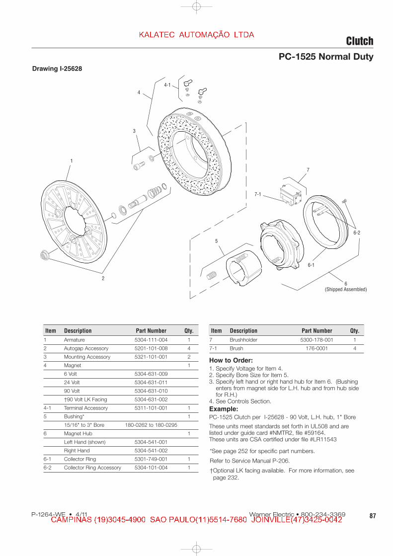
PC-1525 Normal Duty
Drawing I-25628
How to Order:
1. Specify Voltage for Item 4.2. Specify Bore Size for Item 5.3. Specify left hand or right hand hub for Item 6. (Bushing
enters from magnet side for L.H. hub and from hub sidefor R.H.)
4. See Controls Section.
Example:
PC-1525 Clutch per I-25628 - 90 Volt, L.H. hub, 1" Bore
These units meet standards set forth in UL508 and arelisted under guide card #NMTR2, file #59164.These units are CSA certified under file #LR11543
1
2
3
4
4-1
5
7-1
6-1
6-2
6(Shipped Assembled)
7
Item Description Part Number Qty.
1 Armature 5304-111-004 1
2 Autogap Accessory 5201-101-008 4
3 Mounting Accessory 5321-101-001 2
4 Magnet 1
6 Volt 5304-631-009
24 Volt 5304-631-011
90 Volt 5304-631-010
†90 Volt LK Facing 5304-631-002
4-1 Terminal Accessory 5311-101-001 1
5 Bushing* 1
15/16" to 3" Bore 180-0262 to 180-0295
6 Magnet Hub 1
Left Hand (shown) 5304-541-001
Right Hand 5304-541-002
6-1 Collector Ring 5301-749-001 1
6-2 Collector Ring Accessory 5304-101-004 1
Item Description Part Number Qty.
7 Brushholder 5300-178-001 1
7-1 Brush 176-0001 4
*See page 252 for specific part numbers.
Refer to Service Manual P-206.
†Optional LK facing available. For more information, see
page 232.
� � � � � � � � � � � � � � � � � �
� � � � � � � � � � � � � � � � � � � � � � � � � � � � � � � � � � � � � � � � � � � � � � � � � � � � � � � � � � � � �

88 Warner Electric • 800-234-3369 P-1264-WE • 4/11
Clutch
PC-1525 Heavy Duty
Shaft Size .937 – 3.000
Static Torque 700 lb.ft.
Maximum Speed 2,000 rpm
Standard Voltage D.C. 6, 24, 90
Customer Shall Maintain:
1. Splined hub pilot diameter to be concentricwith splined armature center of rotation within .010 T.I.R.
ARMATURE VIEW
COLLECTOR RING VIEW
1.500
4.3134.311
Pilot Dia.
5.750
.093
15.578
RunningDia. Max.
Max. Length ofCustomer Pilot
16.250
.171Max.
.062
.125
.718 Max.
.062 Min.RunningClearance
3/8-16UNC-2A
(Left HandMagnet HubShown)
1.750 2.312
5.109 Max.
.562
3.187
7.781Dia.
3.00
3.781
.397/.388 Dia. (8) holes (hub)equally spaced on 3.625 dia.
Mounting holes are within .003of true position relative to pilot
diameter.
3.062 dia.
See page 252 fordetails on Bushings.
1/2-14 NPSM Am. std.straight pipe tap.
All dimensions are nominal unless
otherwise noted.
Information on inertia and weights begins
on page 239. Coil data is on pages 250
and 251.
� � � � � � � � � � � � � � � � � �
� � � � � � � � � � � � � � � � � � � � � � � � � � � � � � � � � � � � � � � � � � � � � � � � � � � � � � � � � � � � �

89P-1264-WE • 4/11 Warner Electric • 800-234-3369
Clutch
PC-1525 Heavy Duty
Drawing I-25629
1(Shipped
Assembled)
1-5
3
2
1-11-6
1-2
1-3 5-1
4
5
7
8-1
8
6-1
6(Shipped<
Assembled)
6-2
1-4
How to Order:
1. Specify Voltage for Item 5.2. Specify Bore Size for Item 7.3. Specify left hand or right hand hub for Item 6.4. See Controls Section.
Example:
PC-1525 Clutch perI-25629 - 90 Volt, L.H. hub, 1" Bore
These units meet the standards of UL508 and are listedunder guide card #NMTR2, file #59164.These units are CSA certified under file #LR11543.
Item Description Part Number Qty.
1 Armature & Splined
Adapter Assembly 5324-111-001 1
1-1 Armature 5324-111-034 1
1-2 Splined Armature Adapter 104-0011 1
1-3 Autogap Accessory 5323-101-002 1
Autogap Spring 808-0044 1
Retainer Ring 748-0370 1
1-4 Button Head Screw 797-0272 8
1-5 Locknut 661-0004 8
1-6 Retainer Plate 686-0003 1
2 Mounting Accessory 5202-101-001 1
3 Splined Hub 540-0148 1
4 Mounting Accessory 5321-101-001 2
5 Magnet 1
6 Volt 5304-631-009
24 Volt 5304-631-011
90 Volt 5304-631-010
†90 Volt LK Facing 5304-631-002
5-1 Terminal Accessory 5311-101-001 1
6 Magnet Hub Assembly 1
Right Hand 5304-541-002
Left Hand (shown) 5304-541-001
Item Description Part Number Qty.
6-1 Collector Ring 5301-749-001 1
6-2 Collector Ring Accessory 5304-101-004 1
7 Bushing, Taperlock* 180-0262 to 180-0295 1
8 Brushholder 5300-178-001 1
8-1 Brush 176-0001 4
*See page 252 for specific part numbers.
Refer to Service Manual P-206.
†Optional LK facing available. For more information, see
page 232.
� � � � � � � � � � � � � � � � � �
� � � � � � � � � � � � � � � � � � � � � � � � � � � � � � � � � � � � � � � � � � � � � � � � � � � � � � � � � � � � �