Embed Size (px)
Citation preview

Model Item no.CAT6 Cable Tester 157010
Version EN triax.com
CAT6 Cable Tester

Application
1
For checking CAT 5e and CAT 6 cables, (UTP and STP).Can also be used with BNC coaxial cable and modular cables.
Contents
Product Overview 2
Features 3
Product Profile 4
Operation 5
10Base-T Cable Test 5 Modular Cable Test 6 10Base-2 Cable Test 6 Remote Test 7 Test Results 9
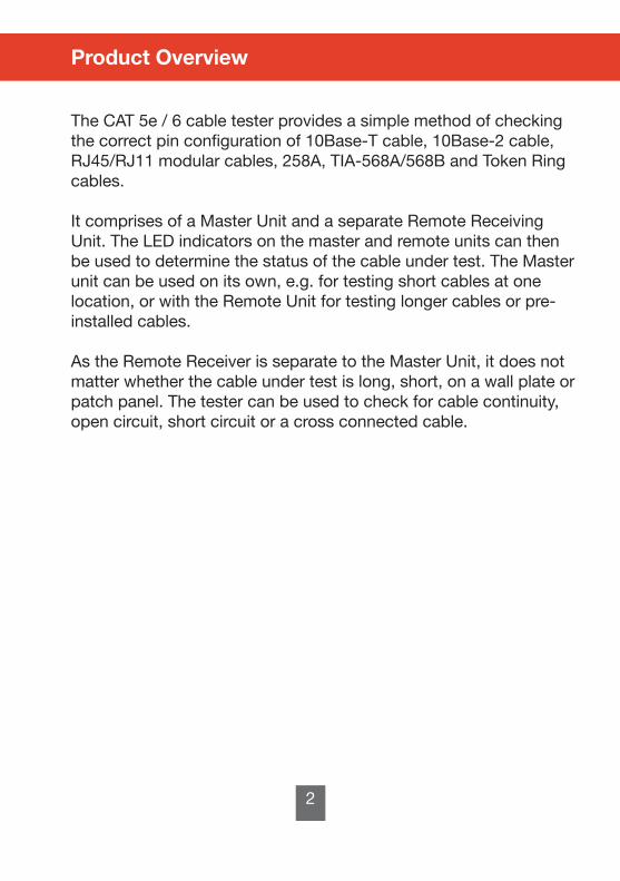
The CAT 5e / 6 cable tester provides a simple method of checking the correct pin configuration of 10Base-T cable, 10Base-2 cable, RJ45/RJ11 modular cables, 258A, TIA-568A/568B and Token Ring cables.
It comprises of a Master Unit and a separate Remote Receiving Unit. The LED indicators on the master and remote units can then be used to determine the status of the cable under test. The Master unit can be used on its own, e.g. for testing short cables at one location, or with the Remote Unit for testing longer cables or pre-installed cables.
As the Remote Receiver is separate to the Master Unit, it does not matter whether the cable under test is long, short, on a wall plate or patch panel. The tester can be used to check for cable continuity, open circuit, short circuit or a cross connected cable.
Product Overview
2
Application
1
For checking CAT 5e and CAT 6 cables, (UTP and STP).Can also be used with BNC coaxial cable and modular cables.
Contents
Product Overview 2
Features 3
Product Profile 4
Operation 5
10Base-T Cable Test 5 Modular Cable Test 6 10Base-2 Cable Test 6 Remote Test 7 Test Results 9
The CAT 5e / 6 cable tester provides a simple method of checking the correct pin configuration of 10Base-T cable, 10Base-2 cable, RJ45/RJ11 modular cables, 258A, TIA-568A/568B and Token Ring cables.
It comprises of a Master Unit and a separate Remote Receiving Unit. The LED indicators on the master and remote units can then be used to determine the status of the cable under test. The Master unit can be used on its own, e.g. for testing short cables at one location, or with the Remote Unit for testing longer cables or pre-installed cables.
As the Remote Receiver is separate to the Master Unit, it does not matter whether the cable under test is long, short, on a wall plate or patch panel. The tester can be used to check for cable continuity, open circuit, short circuit or a cross connected cable.
Product Overview
2
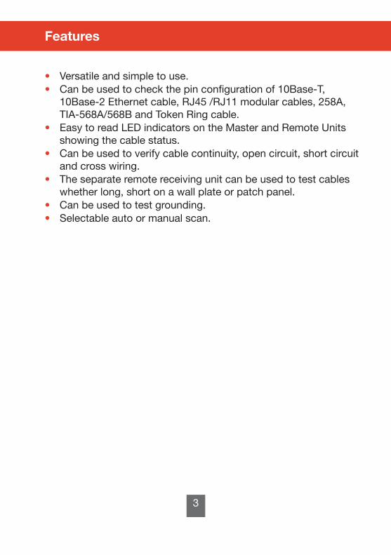
• Versatile and simple to use.• Can be used to check the pin configuration of 10Base-T, 10Base-2 Ethernet cable, RJ45 /RJ11 modular cables, 258A, TIA-568A/568B and Token Ring cable.• Easy to read LED indicators on the Master and Remote Units showing the cable status. • Can be used to verify cable continuity, open circuit, short circuit and cross wiring.• The separate remote receiving unit can be used to test cables whether long, short on a wall plate or patch panel.• Can be used to test grounding.• Selectable auto or manual scan.
Features
3
Product Profile
1 Source RJ45 Jack2 Receiving RJ45 Jack3 LED Display for Sourcing End (Jack 1)4 LED Display for Receiving End (Jack 2)5 Power Switch6 LED Scanning Mode Switch7 Test Switch for Manual Scan8 Remote RJ45 Jack9 LED Display for Receiving End (Same as Jack 2)10 Ground LED for Receiving End11 Battery Compartment (9V) Battery included
4

Loopback test (using the Master Unit):
10Base-T Cable TestPlug one end of the cable under test into the source RJ45 socket, (marked with the p arrow), and the other end of the cable under test into the second, receiving RJ45 socket.
Switch the Master Unit on. The LED’s will start to scan in sequence if the Auto/Manual switch is set to Auto mode or, the LED will light on pin 1 if the Auto/Manual switch is set to Manual mode.
Note: Ensure the battery has sufficient charge or inaccurate results may be obtained.
Use the ‘Auto / Manual’ switch to select the required scan method.When scanning, the upper and lower LED indicators will illuminate simultaneously.
Observe the LED displays. It shows the status of the pin configuration of the cable under test. If you fail to read the result in the first LED scan, in ‘Auto’ mode the scan will repeat continuously. If ‘Manual mode’ is selected, press the test switch to scan the pins one by one. Please refer to picture 1 below.
Operation
5
Picture 1
Modular Cable Test
Please refer to the procedures for 10Base-T Cable Test. However, in this test, the LED display should be as shown in picture 2.Note: You will need to use a RJ45 to RJ11 adaptor, not supplied.
10Base-2 Cable Test
Plug the two RJ45 to BNC adaptor cables (supplied) into the RJ45 sockets on the Master Unit. Connect the BNC cable under test to the BNC connectors on the adaptor cables.For the remaining procedure refer to the 10Base-T cable test on page 7.
Note:The centre pin of the BNC cable should be read on LED 1 and the shielding of the BNC cable should be read on LED 2. Please refer to picture 3 below.
6
Picture 2
Picture 3

As the 10Base-2 cable has only two wires, we suggest you scan using manual mode although ‘Auto’ mode can still be used.
Remote Test (using the Master and Remote Units).
Plug one end of the cable under test to the source RJ45 socket (marked with the p arrow) of the Master Unit and the other end to the receiving RJ45 socket of the remote unit. If the cable under test is already installed on a patch panel or wall plate, you will have to use a suitable adaptor cable (not supplied) to solve the connector gender problem. Please refer to pictures 4 and 5.
Set the Auto/Manual switch to Auto mode if you are carrying out the test alone.
Observe the test result on the LED display of the remote unit.
Note: The LED display on the remote unit is scanned in sequence corresponding to the source end at the master unit.
7 8
Picture 4
Picture 5

Test Result
Continuity: Pin 2 is connected
Open: Pin 2 is Open circuit
Short: Pin 2 and Pin 3 are short circuited
Miswired: Pin 3 and Pin 6 are incorrectly wired
WarningDo not operate the tester in a live circuit because damage may occur to the tester.
If you do not use the tester for a long time, remove the battery from the battery compartment.
9

Copyright © 2016 TRIAX. All rights reserved. The TRIAX Logo and TRIAX, TRIAX Multimedia are registered trademarks or trademarks of the TRIAX Company or its affiliates.All specifications in this guide are subject to change without further notice.
TRIAX A/S | Bjørnkærvej 3 | DK-8783 Hornsyld | Denmark
triax.com/support