Embed Size (px)
Citation preview

REVERSIBLE RATCHETS
Part Nos: 3120110 & 3120116
GC0409
MODEL CAT108 (1/2”) & CAT109 (3/8”)
OPERATING & MAINTENANCEINSTRUCTIONS
2
INTRODUCTION
Thank you for purchasing this CLARKE product.
Before attempting to use the reversible ratchet, please read this manualthoroughly and follow the instructions carefully. In doing so you will ensure thesafety of yourself and that of others around you, and you can look forward tothe reversible ratchet giving you long and satisfactory service.
GUARANTEE
This CLARKE product is guaranteed against faulty manufacture for a period of12 months from the date of purchase. Please keep your receipt as proof ofpurchase.
This guarantee is invalid if the product is found to have been abused ortampered with in any way, or not used for the purpose for which it wasintended.
Faulty goods should be returned to their place of purchase, no product canbe returned to us without prior permission.
This guarantee does not effect your statutory rights.
ENVIROMENTAL PROTECTION
Do not dispose of this product with general household waste. All tools,accessories and packaging should be sorted, taken to a recyclingcentre and disposed of appropriately.
PARTS & SERVICING
For parts & Servicing, please contact your nearest dealer, orCLARKE International, on one of the following numbers.
PARTS & SERVICE TEL: 020 8988 7400PARTS & SERVICE FAX: 020 8558 3622
or e-mail as follows:PARTS: [email protected]
SERVICE: [email protected]
3
CONTENTS
Introduction ............................................................................................ 2
Guarantee .............................................................................................. 2
Environmental Protection ...................................................................... 2
Parts & Service Contacts ....................................................................... 2
Table of Contents ................................................................................... 3
Overview ................................................................................................ 3
General Safety Precautions .................................................................. 4
Air Supply Requirements ....................................................................... 5
Assembly ................................................................................................ 6
Operation ............................................................................................... 7
Maintenance .......................................................................................... 8
Accessories ............................................................................................ 8
Troubleshooting ...................................................................................... 9
Parts Lists and Diagrams ..................................................................... 10
Technical Specification ....................................................................... 11
Vibration Emissions .............................................................................. 12
Declaration of Conformity .................................................................. 14
OVERVIEW
The CAT108 and CAT109 Reversible Ratchets are ideal for use in garages andworkshops. The tool features a steel angle head & aluminium body, frontexhaust & ergonomic grip.
Unpack and lay out the components, checking against the following list. Anydamage or deficiency should be reported to your CLARKE dealerimmediately.
• Reversible ratchet
• Male Snap Connector
• Bottle of Airline Oil
• Operators Manual (this document)
Your reversible ratchet has been designed to give long and trouble freeservice. If, however, having followed the instructions in this booklet carefully,you encounter problems, take the unit to your local CLARKE dealer.
4
SAFETY PRECAUTIONS
WORK ENVIRONMENT
• Keep the work area clean and tidy.
• Dress appropriately - Do not wear loose clothing or jewellery. Tie long hairout of the way.
• Keep children and visitors away - Do not let children handle the tool.Make sure that any other persons in the work area are dressed suitablyand are wearing eye and ear protectors.
• Keep the air supply hose away from heat, oil and sharp edges.
• Do not fit the tool to any stand or clamping device that may damage thetool.
GENERAL USE
• Stay alert and use common sense - do not use the tool when you are tiredor under the influence of alcohol, drugs or medication.
• Always wear eye protection when using the tool - eye protection mustprovide protection from the front and the side.
• Always wear ear protectors when using the tool.
• Do not over-reach - keep proper footing and balance at all times.
• Never use any type of bottled gas as a source of power for the tool.
• Do not connect the air supply hose with your finger on the trigger of thetool.
• Do not exceed the maximum pressure for the tool: 90 psi / 6.2 bar.
• Check hoses for leaks or worn condition before use and ensure that allconnections are secure.
• Do not use the tool for any other purpose than that described in thisbooklet.
• Do not carry out any alterations or modifications to the tool.
• The tool should be serviced as required by your CLARKE dealer.
• Never use the tool if it is defective or operating abnormally.
• ALWAYS ensure the workpiece is firmly secured leaving both hands free tocontrol the tool.
• ALWAYS ensure the tool has stopped before putting it down after use.
• ALWAYS ensure that any attachments are correctly fastened beforeconnecting the tool to the power supply.
5
• Always disconnect from the air supply when:
a) Performing any maintenance.
b) The tool is not in use.
c) The tool will be left unattended.
d) Moving to another work area.
• Avoid damaging the tool for example by applying excessive force.
• ALWAYS maintain the tool with care. Keep it clean for best and safestperformance.
• Quick change air-line couplings should not be located at the tool. Theyadd weight and could fail due to vibration.
• DO NOT force or misuse the tool. It will do a better and safer job at therate for which it was designed.
• This tool vibrates during use. Vibration may be harmful to your hands orarms. Stop using the tool if discomfort, a tingling feeling or pain occurs andseek medical advice before resuming use.
TRANSPORTATION
• Never carry the tool by the air supply hose.
• Never carry the tool with your finger on the trigger.
STORAGE
• When not in use the tool must be disconnected from the air supply andstored in a dry place out of the reach of children (preferably in a lockedcabinet).
• Avoid storage in environments where the temperature is below 0oC.
AIR SUPPLY REQUIREMENTS
WARNING: COMPRESSED AIR CAN BE DANGEROUS. ENSURE THAT YOUARE THOROUGHLY FAMILIAR WITH ALL PRECAUTIONS RELATING TO THEUSE OF COMPRESSORS AND COMPRESSED AIR SUPPLY.
• Air compressors used with the tool must comply with the appropriateEuropean Community safety directives.
• Use only clean, dry, regulated compressed air as a power source.
• A build up of moisture in the air compressor will accelerate wear andcorrosion in the moving parts. Ensure any moisture is drained from thecompressor daily and the inlet filter is kept clean.
6
ASSEMBLY
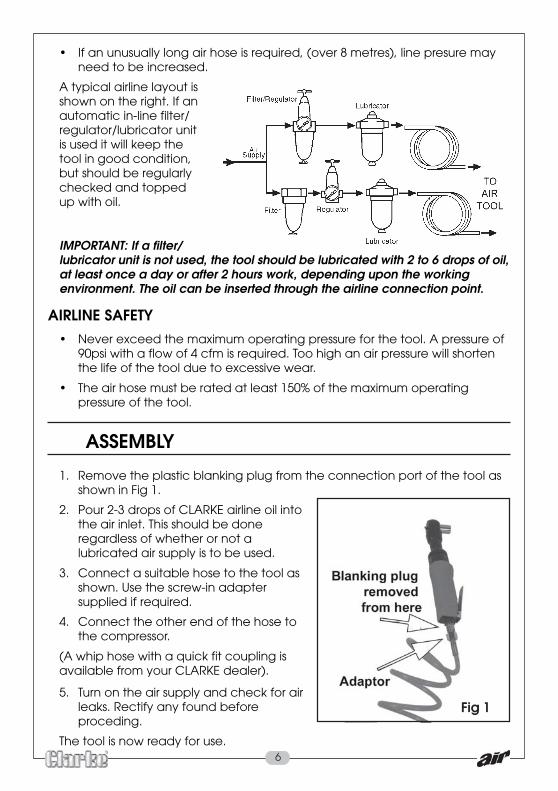
1. Remove the plastic blanking plug from the connection port of the tool asshown in Fig 1.
2. Pour 2-3 drops of CLARKE airline oil intothe air inlet. This should be doneregardless of whether or not alubricated air supply is to be used.
3. Connect a suitable hose to the tool asshown. Use the screw-in adaptersupplied if required.
4. Connect the other end of the hose tothe compressor.
(A whip hose with a quick fit coupling isavailable from your CLARKE dealer).
5. Turn on the air supply and check for airleaks. Rectify any found beforeproceding.
The tool is now ready for use.
• If an unusually long air hose is required, (over 8 metres), line presure mayneed to be increased.
A typical airline layout isshown on the right. If anautomatic in-line filter/regulator/lubricator unitis used it will keep thetool in good condition,but should be regularlychecked and toppedup with oil.
IMPORTANT: If a filter/lubricator unit is not used, the tool should be lubricated with 2 to 6 drops of oil,at least once a day or after 2 hours work, depending upon the workingenvironment. The oil can be inserted through the airline connection point.
AIRLINE SAFETY• Never exceed the maximum operating pressure for the tool. A pressure of
90psi with a flow of 4 cfm is required. Too high an air pressure will shortenthe life of the tool due to excessive wear.
• The air hose must be rated at least 150% of the maximum operatingpressure of the tool.
Fig 1

7
OPERATING INSTRUCTIONS
IMPORTANT: Only use sockets designed for use with a ratchet wrench;- either3/8" (10mm) for the CAT109 or 1/2” (13mm) for the CAT108.
1 Select the socket you require.
2. Press the socket until it clicks intoplace on the square drive.
3. Place the socket over the subjectnut.
• Take care that the socket is firmlyengaged on the nut to betightened or removed.
4. Squeeze the trigger against thebody of the tool to start as in Fig2.
5. Release the trigger to stop thetool.
6. Always ensure the tool hasstopped before putting it down.
7. To change the direction, twist thecontrol at the tip of the tool toeither ‘F’ for forward or ‘R’ forreverse as in Fig 3.
DISCONNECTING THE AIR SUPPLY1. Do not disconnect the air supply hose until the compressor has been shut
down and the compressed air pressure released.
2. Once the pressure has been released, disconnect the air supply hose fromthe tool.
STORAGE1. Store the tool safely in its box in a dry, secure environment.
2. If the tool is not to be used for longer than 24 hours, run a few drops ofCLARKE airline oil into the air inlet and run the tool for a few seconds toensure that the oil has been well distributed throughout the tool.
3. When storing, ensure the blanking plug is replaced on the airlineconnector once the airline has been disconnected.
Fig 2
Fig 3
8
MAINTENANCE
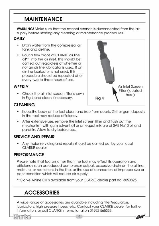
WARNING! Make sure that the ratchet wrench is disconnected from the airsupply before starting any cleaning or maintenance procedures.
DAILY• Drain water from the compressor air
tank and air-line.
• Pour a few drops of CLARKE air lineoil**, into the air inlet. This should becarried out regardless of whether ornot an air line lubricator is used. If anair-line lubricator is not used, thisprocedure should be repeated afterevery two to three hours of use.
WEEKLY• Check the air inlet screen filter shown
in Fig 4 and clean if necessary.
CLEANING• Keep the body of the tool clean and free from debris. Grit or gum deposits
in the tool may reduce efficiency.
• After extensive use, remove the inlet screen filter and flush out themechanism with gum solvent oil or an equal mixture of SAE No10 oil andparaffin. Allow to dry before use.
SERVICE AND REPAIR• Any major servicing and repairs should be carried out by your local
CLARKE dealer.
PERFORMANCEPlease note that factors other than the tool may effect its operation andefficiency such as reduced compressor output, excessive drain on the airline,moisture, or restrictions in the line, or the use of connectors of improper size orpoor condition which will reduce air supply.
**Clarke Airline Oil is available from your CLARKE dealer part no. 3050825.
ACCESSORIES
A wide range of accessories are available including filter/regulators,lubricators, high pressure hoses, etc. Contact your CLARKE dealer for furtherinformation, or call CLARKE International on 01992 565333.
Air Inlet ScreenFilter (located
here)Fig 4
9
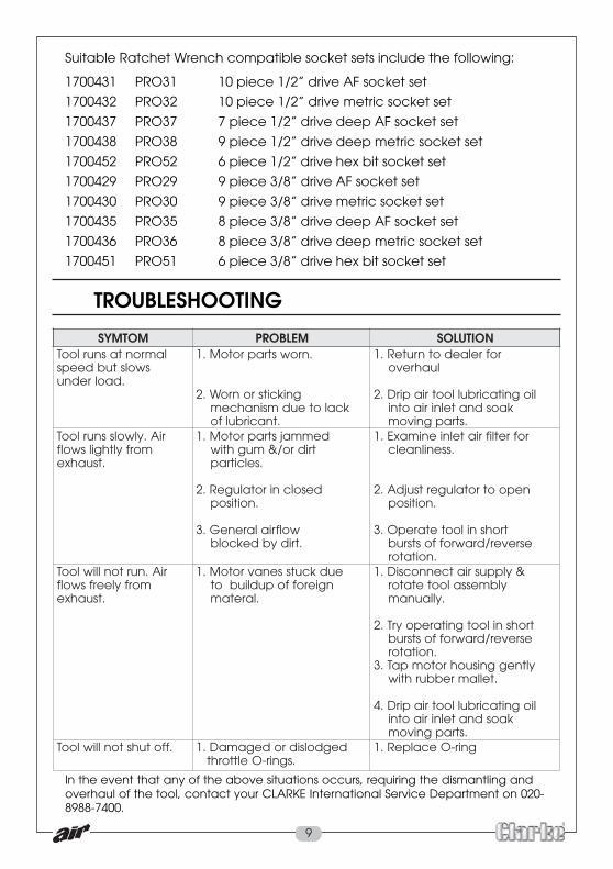
TROUBLESHOOTING
MOTMYS MELBORP NOITULOSsnurlooT lamronta
swolstubdeepsrednu daol .
.nrowstraprotoM.1
gnikcitsronroW.2kcaloteudmsinahcem
.tnacirbulfo
rofrelaedotnruteR.1luahrevo
liognitacirbullootriapirD.2kaosdnatelniriaotni
.strapgnivomriA.ylwolssnurlooT
morfylthgilswolf.tsuahxe
demmajstraprotoM.1tridro/&mughtiw
.selcitrap
desolcnirotalugeR.2.noitisop
wolfrialareneG.3.tridybdekcolb
rofretlifriatelnienimaxE.1.ssenilnaelc
nepootrotalugertsujdA.2.noitisop
trohsnilootetarepO.3esrever/drawroffostsrub
.noitatorriA.nurtonlliwlooT
morfyleerfswolf.tsuahxe
eudkcutssenavrotoM.1ngieroffopudliubot
.laretam
&ylppusriatcennocsiD.1ylbmessalootetator
.yllaunam
trohsnilootgnitarepoyrT.2esrever/drawroffostsrub
.noitator.3 yltneggnisuohrotompaT
.tellamrebburhtiw
liognitacirbullootriapirD.4kaosdnatelniriaotni
.strapgnivom.ffotuhstonlliwlooT degdolsidrodegamaD.1
.sgnir-Oelttorhtgnir-OecalpeR.1
Suitable Ratchet Wrench compatible socket sets include the following:
1700431 PRO31 10 piece 1/2” drive AF socket set
1700432 PRO32 10 piece 1/2” drive metric socket set
1700437 PRO37 7 piece 1/2” drive deep AF socket set
1700438 PRO38 9 piece 1/2” drive deep metric socket set
1700452 PRO52 6 piece 1/2” drive hex bit socket set
1700429 PRO29 9 piece 3/8” drive AF socket set
1700430 PRO30 9 piece 3/8” drive metric socket set
1700435 PRO35 8 piece 3/8” drive deep AF socket set
1700436 PRO36 8 piece 3/8” drive deep metric socket set
1700451 PRO51 6 piece 3/8” drive hex bit socket set
In the event that any of the above situations occurs, requiring the dismantling andoverhaul of the tool, contact your CLARKE International Service Department on 020-8988-7400.
10
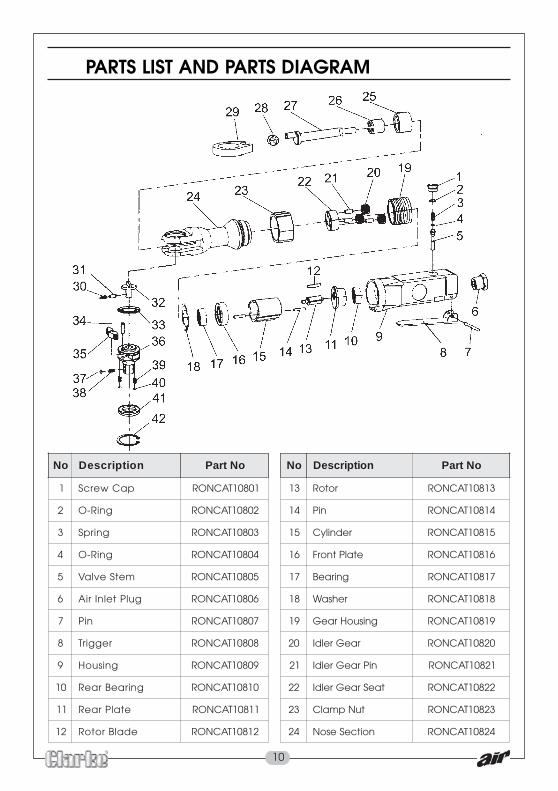
PARTS LIST AND PARTS DIAGRAM
oN noitpircseD oNtraP oN noitpircseD oNtraP
1 paCwercS 10801TACNOR 31 rotoR 31801TACNOR
2 gniR-O 20801TACNOR 41 niP 41801TACNOR
3 gnirpS 30801TACNOR 51 rednilyC 51801TACNOR
4 gniR-O 40801TACNOR 61 etalPtnorF 61801TACNOR
5 metSevlaV 50801TACNOR 71 gniraeB 71801TACNOR
6 gulPtelnIriA 60801TACNOR 81 rehsaW 81801TACNOR
7 niP 70801TACNOR 91 gnisuoHraeG 91801TACNOR
8 reggirT 80801TACNOR 02 raeGreldI 02801TACNOR
9 gnisuoH 90801TACNOR 12 niPraeGreldI 12801TACNOR
01 gniraeBraeR 01801TACNOR 22 taeSraeGreldI 22801TACNOR
11 etalPraeR 11801TACNOR 32 tuNpmalC 32801TACNOR
21 edalBrotoR 21801TACNOR 42 noitceSesoN 42801TACNOR
11
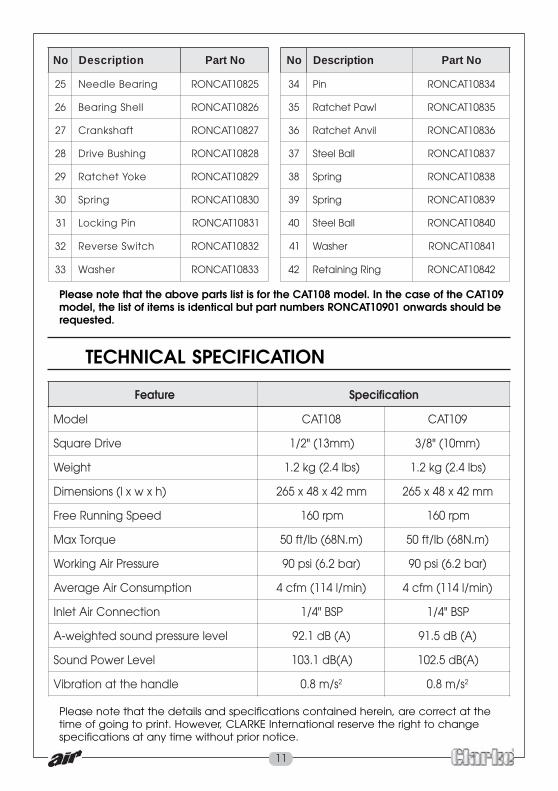
Please note that the details and specifications contained herein, are correct at thetime of going to print. However, CLARKE International reserve the right to changespecifications at any time without prior notice.
TECHNICAL SPECIFICATION
erutaeF noitacificepS
ledoM 801TAC 901TAC
evirDerauqS )mm31("2/1 )mm01("8/3
thgieW )sbl4.2(gk2.1 )sbl4.2(gk2.1
)hxwxl(snoisnemiD mm24x84x562 mm24x84x562
deepSgninnuReerF mpr061 mpr061
euqroTxaM )m.N86(bl/tf05 )m.N86(bl/tf05
erusserPriAgnikroW )rab2.6(isp09 )rab2.6(isp09
noitpmusnoCriAegarevA )nim/l411(mfc4 )nim/l411(mfc4
noitcennoCriAtelnI PSB"4/1 PSB"4/1
levelerusserpdnuosdethgiew-A )A(Bd1.29 )A(Bd5.19
leveLrewoPdnuoS )A(Bd1.301 )A(Bd5.201
eldnahehttanoitarbiV s/m8.0 2 s/m8.0 2
oN noitpircseD oNtraP oN noitpircseD oNtraP
52 gniraeBeldeeN 52801TACNOR 43 niP 43801TACNOR
62 llehSgniraeB 62801TACNOR 53 lwaPtehctaR 53801TACNOR
72 tfahsknarC 72801TACNOR 63 livnAtehctaR 63801TACNOR
82 gnihsuBevirD 82801TACNOR 73 llaBleetS 73801TACNOR
92 ekoYtehctaR 92801TACNOR 83 gnirpS 83801TACNOR
03 gnirpS 03801TACNOR 93 gnirpS 93801TACNOR
13 niPgnikcoL 13801TACNOR 04 llaBleetS 04801TACNOR
23 hctiwSesreveR 23801TACNOR 14 rehsaW 14801TACNOR
33 rehsaW 33801TACNOR 24 gniRgniniateR 24801TACNOR
Please note that the above parts list is for the CAT108 model. In the case of the CAT109model, the list of items is identical but part numbers RONCAT10901 onwards should berequested.

12
VIBRATION EMISSIONS
MODEL No: CAT108 & CAT109DESCRIPTION: REVERSIBLE RATCHETS
Declared vibration emission value in accordancewith EN12096
Measured vibration emission value - a: less than2.5m/s2
Values determined according to EN28662-1
Employers are advised to refer to the HSE publication “Guide for Employers”.
All hand held power tools vibrate to some extent, and this vibration istransmitted to the operator via the handle, or hand used to steady the tool.Vibration from about 2 to 1500 herz is potentially damaging and is mosthazardous in the range from about 5 to 20 herz.
Operators who are regularly exposed to vibration may suffer from Hand ArmVibration Syndrome (HAVS), which includes ‘dead hand’, ‘dead finger’, and‘white finger’. These are painful conditions and are widespread in industrieswhere vibrating tools are used.
The health risk depends upon the vibration level and the length of time ofexposure to it……in effect, a daily vibration dose.
Tools are tested using specialised equipment, to approximate the vibrationlevel generated under normal, acceptable operating conditions for the toolin question. For example, a grinder used at 45° on mild steel plate, or asander on softwood in a horizontal plane etc.
These tests produce a value ‘a’, expressed in metres per second per second,which represents the average vibration level of all tests taken, in three axeswhere necessary, and a second figure ‘K’, which represents the uncertaintyfactor, i.e. a value in excess of ‘a’, to which the tool could vibrate undernormal conditions. These values appear in the specification panel below.
HAND-ARM VIBRATION
13
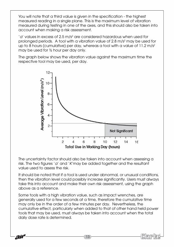
You will note that a third value is given in the specification - the highestmeasured reading in a single plane. This is the maximum level of vibrationmeasured during testing in one of the axes, and this should also be taken intoaccount when making a risk assessment.
‘a’ values in excess of 2.5 m/s2 are considered hazardous when used forprolonged periods. A tool with a vibration value of 2.8 m/s2 may be used forup to 8 hours (cumulative) per day, whereas a tool with a value of 11.2 m/s2
may be used for ½ hour per day only.
The graph below shows the vibration value against the maximum time therespective tool may be used, per day.
The uncertainty factor should also be taken into account when assessing arisk. The two figures ‘a’ and ‘K’may be added together and the resultantvalue used to assess the risk.
It should be noted that if a tool is used under abnormal, or unusual conditions,then the vibration level could possibly increase significantly. Users must alwaystake this into account and make their own risk assessment, using the graphabove as a reference.
Some tools with a high vibration value, such as impact wrenches, aregenerally used for a few seconds at a time, therefore the cumulative timemay only be in the order of a few minutes per day. Nevertheless, thecumulative effect, particularly when added to that of other hand held powertools that may be used, must always be taken into account when the totaldaily dose rate is determined.

14
DECLARATION OF CONFORMITY

15
DECLARATION OF CONFORMITY