Embed Size (px)
DESCRIPTION
exelent
Citation preview

®© 2010 CaterpillarAll Rights Reserved
®
SAFETYOperation and Maintenance Manual Excerpt
SEBU7364-07January 2010
Operation andMaintenanceManual322C ExcavatorDAA1-Up (Machine)FED1-Up (Machine)BKM1-Up (Machine)BLP1-Up (Machine)
SAFETY.CAT.COM
i03684547
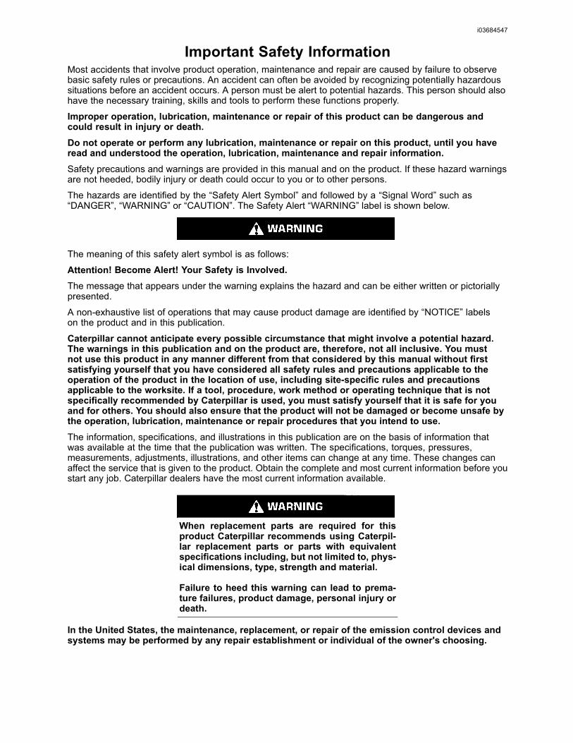
Important Safety InformationMost accidents that involve product operation, maintenance and repair are caused by failure to observebasic safety rules or precautions. An accident can often be avoided by recognizing potentially hazardoussituations before an accident occurs. A person must be alert to potential hazards. This person should alsohave the necessary training, skills and tools to perform these functions properly.
Improper operation, lubrication, maintenance or repair of this product can be dangerous andcould result in injury or death.Do not operate or perform any lubrication, maintenance or repair on this product, until you haveread and understood the operation, lubrication, maintenance and repair information.Safety precautions and warnings are provided in this manual and on the product. If these hazard warningsare not heeded, bodily injury or death could occur to you or to other persons.
The hazards are identified by the “Safety Alert Symbol” and followed by a “Signal Word” such as“DANGER”, “WARNING” or “CAUTION”. The Safety Alert “WARNING” label is shown below.
The meaning of this safety alert symbol is as follows:
Attention! Become Alert! Your Safety is Involved.The message that appears under the warning explains the hazard and can be either written or pictoriallypresented.
A non-exhaustive list of operations that may cause product damage are identified by “NOTICE” labelson the product and in this publication.
Caterpillar cannot anticipate every possible circumstance that might involve a potential hazard.The warnings in this publication and on the product are, therefore, not all inclusive. You mustnot use this product in any manner different from that considered by this manual without firstsatisfying yourself that you have considered all safety rules and precautions applicable to theoperation of the product in the location of use, including site-specific rules and precautionsapplicable to the worksite. If a tool, procedure, work method or operating technique that is notspecifically recommended by Caterpillar is used, you must satisfy yourself that it is safe for youand for others. You should also ensure that the product will not be damaged or become unsafe bythe operation, lubrication, maintenance or repair procedures that you intend to use.The information, specifications, and illustrations in this publication are on the basis of information thatwas available at the time that the publication was written. The specifications, torques, pressures,measurements, adjustments, illustrations, and other items can change at any time. These changes canaffect the service that is given to the product. Obtain the complete and most current information before youstart any job. Caterpillar dealers have the most current information available.
When replacement parts are required for thisproduct Caterpillar recommends using Caterpil-lar replacement parts or parts with equivalentspecifications including, but not limited to, phys-ical dimensions, type, strength and material.
Failure to heed this warning can lead to prema-ture failures, product damage, personal injury ordeath.
In the United States, the maintenance, replacement, or repair of the emission control devices andsystems may be performed by any repair establishment or individual of the owner's choosing.
6 SEBU7364-07Safety SectionSafety Messages
Safety Sectioni02216704
Safety Messages(Arrangement I)SMCS Code: 7000; 7405
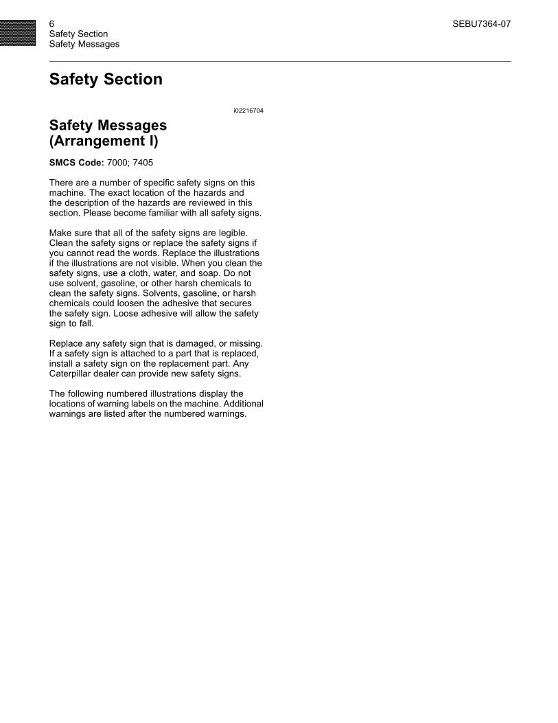
There are a number of specific safety signs on thismachine. The exact location of the hazards andthe description of the hazards are reviewed in thissection. Please become familiar with all safety signs.
Make sure that all of the safety signs are legible.Clean the safety signs or replace the safety signs ifyou cannot read the words. Replace the illustrationsif the illustrations are not visible. When you clean thesafety signs, use a cloth, water, and soap. Do notuse solvent, gasoline, or other harsh chemicals toclean the safety signs. Solvents, gasoline, or harshchemicals could loosen the adhesive that securesthe safety sign. Loose adhesive will allow the safetysign to fall.
Replace any safety sign that is damaged, or missing.If a safety sign is attached to a part that is replaced,install a safety sign on the replacement part. AnyCaterpillar dealer can provide new safety signs.
The following numbered illustrations display thelocations of warning labels on the machine. Additionalwarnings are listed after the numbered warnings.
SEBU7364-07 7Safety Section
Safety Messages
g00893100Illustration 2Warning labels in cab of machine
8 SEBU7364-07Safety SectionSafety Messages
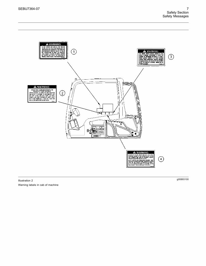
g00910801Illustration 3
Top view of machine
g00910806Illustration 4Right side of machine
SEBU7364-07 9Safety Section
Safety Messages
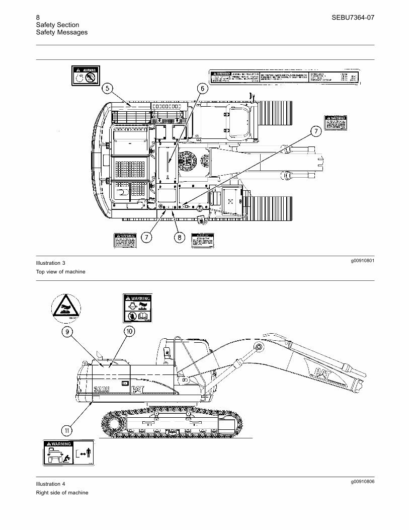
g00910808Illustration 5
Left side of machine
(1) Do Not OperateThis warning label is positioned on the right side ofthe cab.
Do not operate or work on this machine unlessyou have read and understand the instructionsand warnings in the Operation and MaintenanceManual. Failure to follow the instructions or heedthe warnings could result in injury or death. Con-tact any Caterpillar dealer for replacement manu-als. Proper care is your responsibility.
(2) Height and Reach of MachineThis warning label is positioned in the cab.
KNOW THE MAXIMUM HEIGHT AND REACH OFYOUR MACHINE. SERIOUS INJURY OR DEATHBY ELECTROCUTION CAN OCCUR IF MACHINEOR ATTACHMENTS ARE NOT KEPT A SAFEDISTANCE FROM ELECTRICAL POWER LINES.KEEP DISTANCE AT LEAST 3 M (10 FEET) PLUSADDITIONAL 10 MM (0.4 INCH) FOR EACH 1,000VOLTS OVER 50,000 VOLTS.
10 SEBU7364-07Safety SectionSafety Messages
(3) Travel Speed Control SwitchThis warning label is positioned in the cab.
Put travel speed control switch in LOW positionbefore descending a slope or loading or unload-ing on trailer. If travel speed control switch is inHIGH position during these operations, suddenchanges in machine speed can occur with an ad-verse effect on machine control, resulting in per-sonal injury.
(4) Automatic Engine SpeedControl (AEC)This warning label is positioned in the cab.
Automatic Engine Speed Control (AEC) will in-crease engine speed automatically when youoperate the control lever(s) and/or travel pedalswhen in position TWO.
When loading and unloading machine from truckor working in close quarters, always have AECswitch in position ONE to prevent any possibili-ty of sudden movement of machine, which couldresult in serious injury or death.
(5) Do Not Use EtherThis warning label is positioned on the cover ofthe intake duct of the air cleaner. The followinginformation is not applicable to machines that areequipped with an ether starting aid.
Since this machine is equipped with an air inletheater, ether should not be used for starting. Us-ing ether can create explosions or fires that cancause personal injury or death. Follow the start-ing procedure in the Operation and MaintenanceManual.
(6) High Pressure GasThis warning label is positioned on the accumulator.
This system contains high pressure gas. Failure tofollow the instructions and warnings could causean explosion, resulting in possible injury or death.
Do not expose to fire. Do not weld. Do not drill.Relieve pressure before discharging.
See Operation and Maintenance Manual for charg-ing and discharging. See your Caterpillar Dealerfor tools and detailed information.
(7) Lift Eyes Can FailThis warning label is located on the top of thehydraulic tank and on top of the fuel tank.
LIFT EYES OR TANK CAN FAIL WHEN LIFTINGTANK CONTAINING FLUIDS RESULTING IN POS-SIBLE PERSONAL INJURY. DRAIN TANK OF ALLFLUIDS BEFORE LIFTING.
(8) Relieve Hydraulic Tank PressureThis warning label is located on top of the hydraulictank.
HYDRAULIC TANK
RELIEVE TANKPRESSUREWITH ENGINEOFF BYREMOVING CAP SLOWLY TO PREVENT BURNSFROM HOT OIL.
(9) Hot SurfaceThis warning label is located inside the enginecompartment and on top of the hydraulic tank.
Avoid contact with hot surfaces. Exhaust pipingand engine components become hot during en-gine operation and cool slowly after engine shut-down. Any contact with hot surfaces can cause se-vere burns.
SEBU7364-07 11Safety Section
Safety Messages
(10) Pressurized SystemThis warning label is located inside the enginecompartment next to the cooling system filler cap.
Pressurized system: Hot coolant can cause seri-ous burn. To open cap, stop engine, wait until ra-diator is cool. Then loosen cap slowly to relievethe pressure.
(11) Machine SwingsThis warning label is located in two places on therear of each side of the machine.
Machine swings. Stay back. Crushing hazardcould cause serious injury or death.
(12) Improper Connections forJump Start CablesThis warning label is positioned on the circuit breakerpanel.
IMPROPER JUMPER CABLE CONNECTIONS CANCAUSE EXPLOSION RESULTING IN PERSONALINJURY.
BATTERIES MAY BE LOCATED IN SEPARATECOMPARTMENTS. WHEN USING JUMPER CA-BLES, ALWAYS CONNECT POSITIVE (+) CABLETO POSITIVE (+) TERMINAL OF BATTERY CON-NECTED TO STARTER SOLENOID AND NEGA-TIVE (-) CABLE FROM EXTERNAL SOURCE TOSTARTER NEGATIVE (-) TERMINAL (IF MACHINENOT EQUIPPED WITH STARTER NEGATIVE TER-MINAL, CONNECT TO ENGINE BLOCK.) FOLLOWPROCEDURE IN THE OPERATION MANUAL.
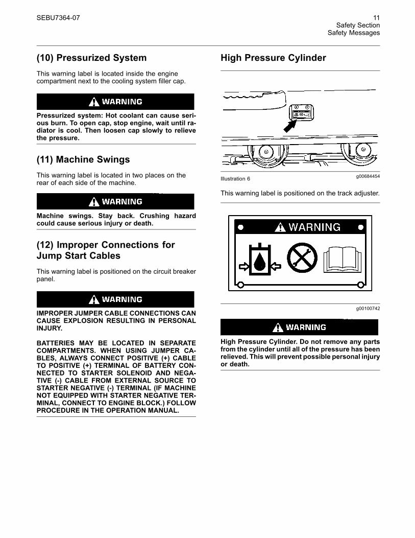
High Pressure Cylinder
g00684454Illustration 6
This warning label is positioned on the track adjuster.
g00100742
High Pressure Cylinder. Do not remove any partsfrom the cylinder until all of the pressure has beenrelieved. This will prevent possible personal injuryor death.
12 SEBU7364-07Safety SectionSafety Messages
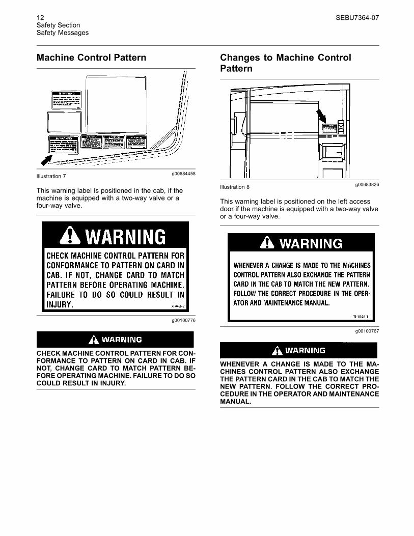
Machine Control Pattern
g00684458Illustration 7
This warning label is positioned in the cab, if themachine is equipped with a two-way valve or afour-way valve.
g00100776
CHECKMACHINE CONTROL PATTERN FOR CON-FORMANCE TO PATTERN ON CARD IN CAB. IFNOT, CHANGE CARD TO MATCH PATTERN BE-FORE OPERATINGMACHINE. FAILURE TO DO SOCOULD RESULT IN INJURY.
Changes to Machine ControlPattern
g00683826Illustration 8
This warning label is positioned on the left accessdoor if the machine is equipped with a two-way valveor a four-way valve.
g00100767
WHENEVER A CHANGE IS MADE TO THE MA-CHINES CONTROL PATTERN ALSO EXCHANGETHE PATTERN CARD IN THE CAB TO MATCH THENEW PATTERN. FOLLOW THE CORRECT PRO-CEDURE IN THE OPERATOR ANDMAINTENANCEMANUAL.
SEBU7364-07 13Safety Section
Safety Messages
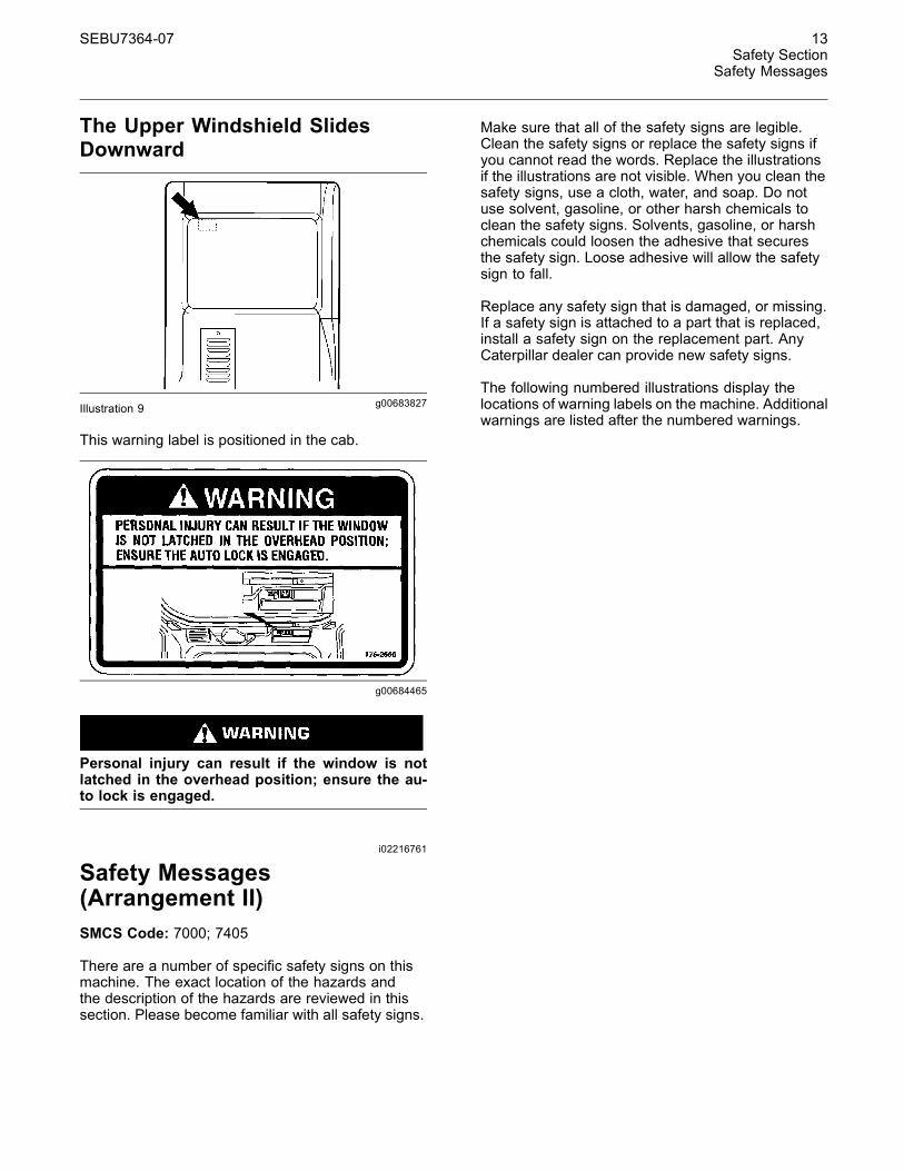
The Upper Windshield SlidesDownward
g00683827Illustration 9
This warning label is positioned in the cab.
g00684465
Personal injury can result if the window is notlatched in the overhead position; ensure the au-to lock is engaged.
i02216761
Safety Messages(Arrangement II)SMCS Code: 7000; 7405
There are a number of specific safety signs on thismachine. The exact location of the hazards andthe description of the hazards are reviewed in thissection. Please become familiar with all safety signs.
Make sure that all of the safety signs are legible.Clean the safety signs or replace the safety signs ifyou cannot read the words. Replace the illustrationsif the illustrations are not visible. When you clean thesafety signs, use a cloth, water, and soap. Do notuse solvent, gasoline, or other harsh chemicals toclean the safety signs. Solvents, gasoline, or harshchemicals could loosen the adhesive that securesthe safety sign. Loose adhesive will allow the safetysign to fall.
Replace any safety sign that is damaged, or missing.If a safety sign is attached to a part that is replaced,install a safety sign on the replacement part. AnyCaterpillar dealer can provide new safety signs.
The following numbered illustrations display thelocations of warning labels on the machine. Additionalwarnings are listed after the numbered warnings.
14 SEBU7364-07Safety SectionSafety Messages
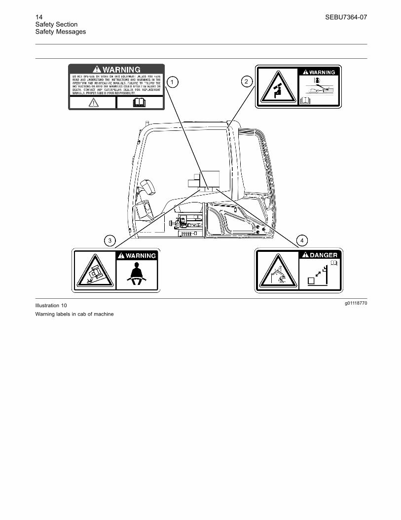
g01118770Illustration 10
Warning labels in cab of machine
SEBU7364-07 15Safety Section
Safety Messages
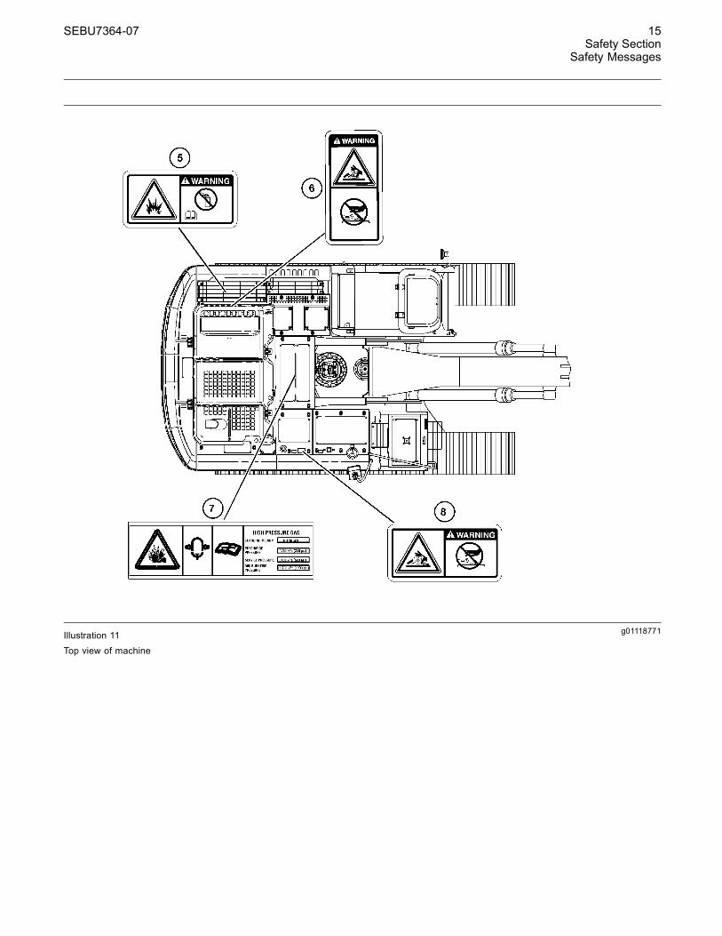
g01118771Illustration 11Top view of machine
16 SEBU7364-07Safety SectionSafety Messages
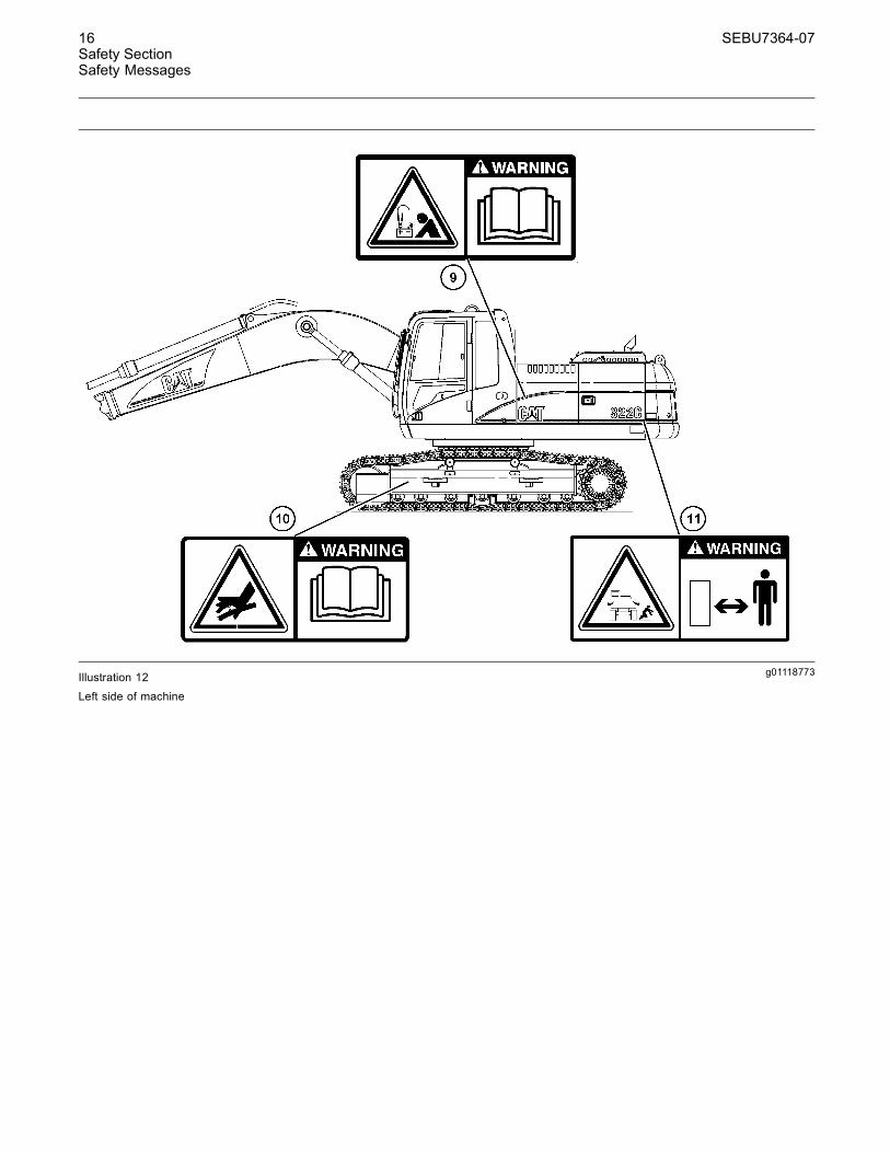
g01118773Illustration 12
Left side of machine
SEBU7364-07 17Safety Section
Safety Messages
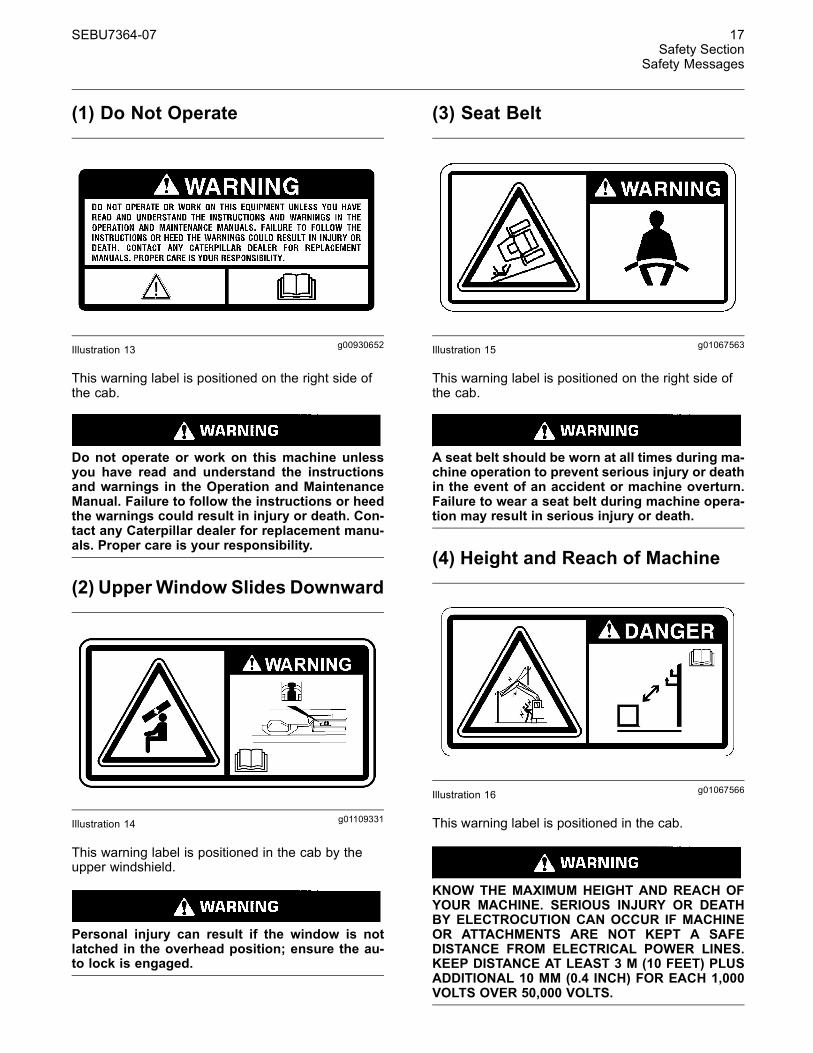
(1) Do Not Operate
g00930652Illustration 13
This warning label is positioned on the right side ofthe cab.
Do not operate or work on this machine unlessyou have read and understand the instructionsand warnings in the Operation and MaintenanceManual. Failure to follow the instructions or heedthe warnings could result in injury or death. Con-tact any Caterpillar dealer for replacement manu-als. Proper care is your responsibility.
(2) Upper Window Slides Downward
g01109331Illustration 14
This warning label is positioned in the cab by theupper windshield.
Personal injury can result if the window is notlatched in the overhead position; ensure the au-to lock is engaged.
(3) Seat Belt
g01067563Illustration 15
This warning label is positioned on the right side ofthe cab.
A seat belt should be worn at all times during ma-chine operation to prevent serious injury or deathin the event of an accident or machine overturn.Failure to wear a seat belt during machine opera-tion may result in serious injury or death.
(4) Height and Reach of Machine
g01067566Illustration 16
This warning label is positioned in the cab.
KNOW THE MAXIMUM HEIGHT AND REACH OFYOUR MACHINE. SERIOUS INJURY OR DEATHBY ELECTROCUTION CAN OCCUR IF MACHINEOR ATTACHMENTS ARE NOT KEPT A SAFEDISTANCE FROM ELECTRICAL POWER LINES.KEEP DISTANCE AT LEAST 3 M (10 FEET) PLUSADDITIONAL 10 MM (0.4 INCH) FOR EACH 1,000VOLTS OVER 50,000 VOLTS.
18 SEBU7364-07Safety SectionSafety Messages
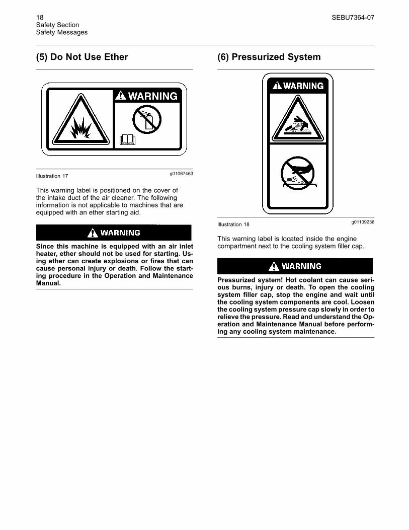
(5) Do Not Use Ether
g01067463Illustration 17
This warning label is positioned on the cover ofthe intake duct of the air cleaner. The followinginformation is not applicable to machines that areequipped with an ether starting aid.
Since this machine is equipped with an air inletheater, ether should not be used for starting. Us-ing ether can create explosions or fires that cancause personal injury or death. Follow the start-ing procedure in the Operation and MaintenanceManual.
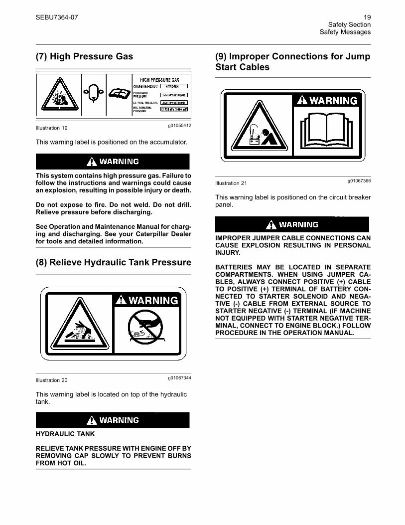
(6) Pressurized System
g01109238Illustration 18
This warning label is located inside the enginecompartment next to the cooling system filler cap.
Pressurized system! Hot coolant can cause seri-ous burns, injury or death. To open the coolingsystem filler cap, stop the engine and wait untilthe cooling system components are cool. Loosenthe cooling system pressure cap slowly in order torelieve the pressure. Read and understand the Op-eration and Maintenance Manual before perform-ing any cooling system maintenance.
SEBU7364-07 19Safety Section
Safety Messages
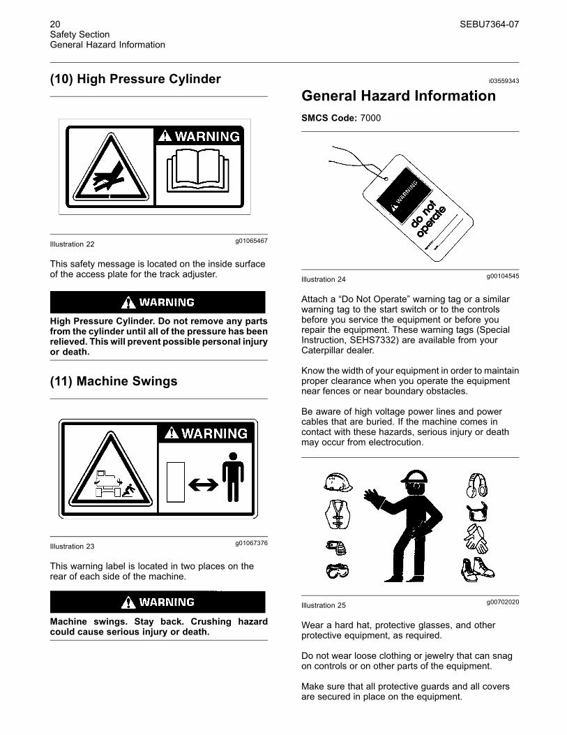
(7) High Pressure Gas
g01055412Illustration 19
This warning label is positioned on the accumulator.
This system contains high pressure gas. Failure tofollow the instructions and warnings could causean explosion, resulting in possible injury or death.
Do not expose to fire. Do not weld. Do not drill.Relieve pressure before discharging.
See Operation and Maintenance Manual for charg-ing and discharging. See your Caterpillar Dealerfor tools and detailed information.
(8) Relieve Hydraulic Tank Pressure
g01067344Illustration 20
This warning label is located on top of the hydraulictank.
HYDRAULIC TANK
RELIEVE TANKPRESSUREWITH ENGINEOFF BYREMOVING CAP SLOWLY TO PREVENT BURNSFROM HOT OIL.
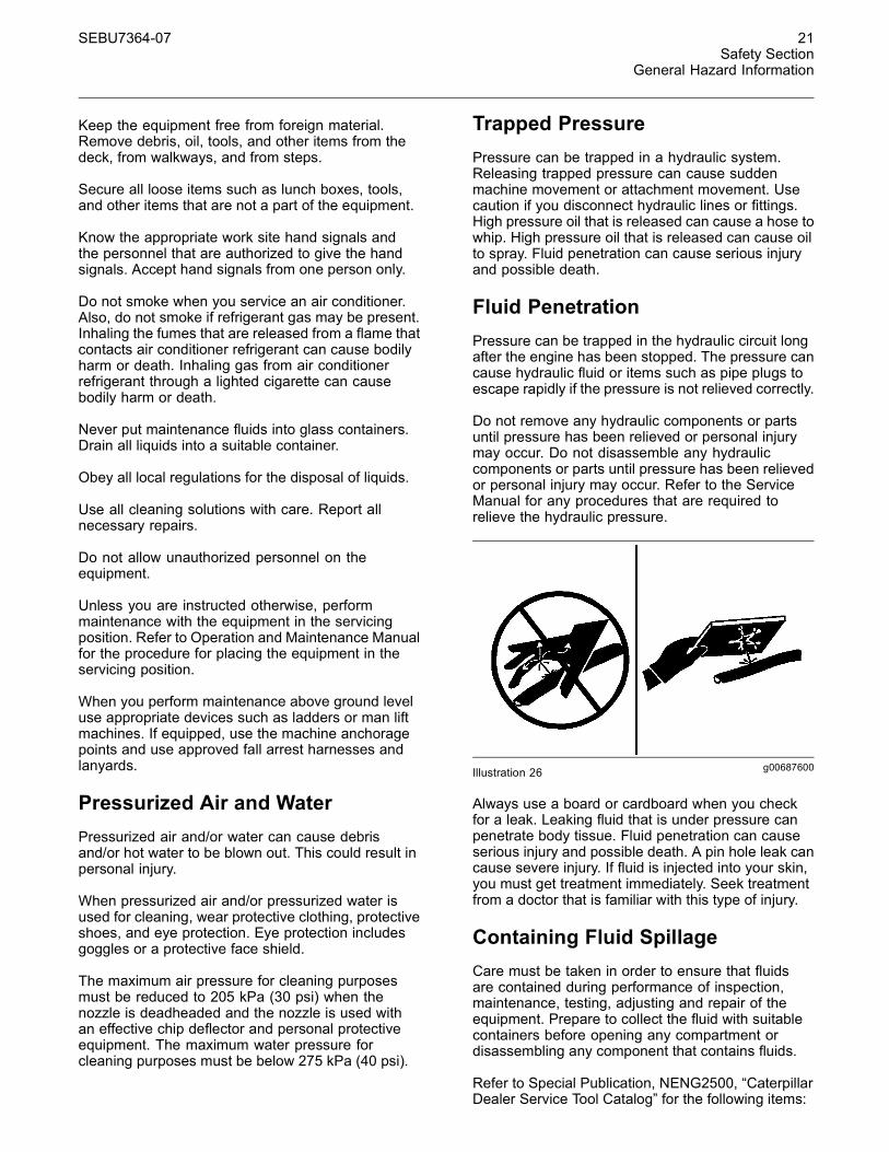
(9) Improper Connections for JumpStart Cables
g01067366Illustration 21
This warning label is positioned on the circuit breakerpanel.
IMPROPER JUMPER CABLE CONNECTIONS CANCAUSE EXPLOSION RESULTING IN PERSONALINJURY.
BATTERIES MAY BE LOCATED IN SEPARATECOMPARTMENTS. WHEN USING JUMPER CA-BLES, ALWAYS CONNECT POSITIVE (+) CABLETO POSITIVE (+) TERMINAL OF BATTERY CON-NECTED TO STARTER SOLENOID AND NEGA-TIVE (-) CABLE FROM EXTERNAL SOURCE TOSTARTER NEGATIVE (-) TERMINAL (IF MACHINENOT EQUIPPED WITH STARTER NEGATIVE TER-MINAL, CONNECT TO ENGINE BLOCK.) FOLLOWPROCEDURE IN THE OPERATION MANUAL.
20 SEBU7364-07Safety SectionGeneral Hazard Information
(10) High Pressure Cylinder
g01065467Illustration 22
This safety message is located on the inside surfaceof the access plate for the track adjuster.
High Pressure Cylinder. Do not remove any partsfrom the cylinder until all of the pressure has beenrelieved. This will prevent possible personal injuryor death.
(11) Machine Swings
g01067376Illustration 23
This warning label is located in two places on therear of each side of the machine.
Machine swings. Stay back. Crushing hazardcould cause serious injury or death.
i03559343
General Hazard InformationSMCS Code: 7000
g00104545Illustration 24
Attach a “Do Not Operate” warning tag or a similarwarning tag to the start switch or to the controlsbefore you service the equipment or before yourepair the equipment. These warning tags (SpecialInstruction, SEHS7332) are available from yourCaterpillar dealer.
Know the width of your equipment in order to maintainproper clearance when you operate the equipmentnear fences or near boundary obstacles.
Be aware of high voltage power lines and powercables that are buried. If the machine comes incontact with these hazards, serious injury or deathmay occur from electrocution.
g00702020Illustration 25
Wear a hard hat, protective glasses, and otherprotective equipment, as required.
Do not wear loose clothing or jewelry that can snagon controls or on other parts of the equipment.
Make sure that all protective guards and all coversare secured in place on the equipment.
SEBU7364-07 21Safety Section
General Hazard Information
Keep the equipment free from foreign material.Remove debris, oil, tools, and other items from thedeck, from walkways, and from steps.
Secure all loose items such as lunch boxes, tools,and other items that are not a part of the equipment.
Know the appropriate work site hand signals andthe personnel that are authorized to give the handsignals. Accept hand signals from one person only.
Do not smoke when you service an air conditioner.Also, do not smoke if refrigerant gas may be present.Inhaling the fumes that are released from a flame thatcontacts air conditioner refrigerant can cause bodilyharm or death. Inhaling gas from air conditionerrefrigerant through a lighted cigarette can causebodily harm or death.
Never put maintenance fluids into glass containers.Drain all liquids into a suitable container.
Obey all local regulations for the disposal of liquids.
Use all cleaning solutions with care. Report allnecessary repairs.
Do not allow unauthorized personnel on theequipment.
Unless you are instructed otherwise, performmaintenance with the equipment in the servicingposition. Refer to Operation and Maintenance Manualfor the procedure for placing the equipment in theservicing position.
When you perform maintenance above ground leveluse appropriate devices such as ladders or man liftmachines. If equipped, use the machine anchoragepoints and use approved fall arrest harnesses andlanyards.
Pressurized Air and WaterPressurized air and/or water can cause debrisand/or hot water to be blown out. This could result inpersonal injury.
When pressurized air and/or pressurized water isused for cleaning, wear protective clothing, protectiveshoes, and eye protection. Eye protection includesgoggles or a protective face shield.
The maximum air pressure for cleaning purposesmust be reduced to 205 kPa (30 psi) when thenozzle is deadheaded and the nozzle is used withan effective chip deflector and personal protectiveequipment. The maximum water pressure forcleaning purposes must be below 275 kPa (40 psi).
Trapped PressurePressure can be trapped in a hydraulic system.Releasing trapped pressure can cause suddenmachine movement or attachment movement. Usecaution if you disconnect hydraulic lines or fittings.High pressure oil that is released can cause a hose towhip. High pressure oil that is released can cause oilto spray. Fluid penetration can cause serious injuryand possible death.
Fluid PenetrationPressure can be trapped in the hydraulic circuit longafter the engine has been stopped. The pressure cancause hydraulic fluid or items such as pipe plugs toescape rapidly if the pressure is not relieved correctly.
Do not remove any hydraulic components or partsuntil pressure has been relieved or personal injurymay occur. Do not disassemble any hydrauliccomponents or parts until pressure has been relievedor personal injury may occur. Refer to the ServiceManual for any procedures that are required torelieve the hydraulic pressure.
g00687600Illustration 26
Always use a board or cardboard when you checkfor a leak. Leaking fluid that is under pressure canpenetrate body tissue. Fluid penetration can causeserious injury and possible death. A pin hole leak cancause severe injury. If fluid is injected into your skin,you must get treatment immediately. Seek treatmentfrom a doctor that is familiar with this type of injury.
Containing Fluid SpillageCare must be taken in order to ensure that fluidsare contained during performance of inspection,maintenance, testing, adjusting and repair of theequipment. Prepare to collect the fluid with suitablecontainers before opening any compartment ordisassembling any component that contains fluids.
Refer to Special Publication, NENG2500, “CaterpillarDealer Service Tool Catalog” for the following items:
22 SEBU7364-07Safety SectionCrushing Prevention and Cutting Prevention
• Tools that are suitable for collecting fluids andequipment that is suitable for collecting fluids
• Tools that are suitable for containing fluids andequipment that is suitable for containing fluids
Obey all local regulations for the disposal of liquids.
Asbestos Information
g00702022Illustration 27
Caterpillar equipment and replacement parts that areshipped from Caterpillar are asbestos free. Caterpillarrecommends the use of only genuine Caterpillarreplacement parts. Use the following guidelineswhen you handle any replacement parts that containasbestos or when you handle asbestos debris.
Use caution. Avoid inhaling dust that might begenerated when you handle components that containasbestos fibers. Inhaling this dust can be hazardousto your health. The components that may containasbestos fibers are brake pads, brake bands, liningmaterial, clutch plates, and some gaskets. Theasbestos that is used in these components is usuallybound in a resin or sealed in some way. Normalhandling is not hazardous unless airborne dust thatcontains asbestos is generated.
If dust that may contain asbestos is present, thereare several guidelines that should be followed:
• Never use compressed air for cleaning.
• Avoid brushing materials that contain asbestos.
• Avoid grinding materials that contain asbestos.
• Use a wet method in order to clean up asbestosmaterials.
• A vacuum cleaner that is equipped with a highefficiency particulate air filter (HEPA) can also beused.
• Use exhaust ventilation on permanent machiningjobs.
• Wear an approved respirator if there is no otherway to control the dust.
• Comply with applicable rules and regulationsfor the work place. In the United States, useOccupational Safety and Health Administration(OSHA) requirements. These OSHA requirementscan be found in “29 CFR 1910.1001”.
• Obey environmental regulations for the disposalof asbestos.
• Stay away from areas that might have asbestosparticles in the air.
Dispose of Waste Properly
g00706404Illustration 28
Improperly disposing of waste can threaten theenvironment. Potentially harmful fluids should bedisposed of according to local regulations.
Always use leakproof containers when you drainfluids. Do not pour waste onto the ground, down adrain, or into any source of water.
i01359664
Crushing Prevention andCutting PreventionSMCS Code: 7000
Support the equipment properly before you performany work or maintenance beneath that equipment.Do not depend on the hydraulic cylinders to holdup the equipment. Equipment can fall if a control ismoved, or if a hydraulic line breaks.
Do not work beneath the cab of the machine unlessthe cab is properly supported.
SEBU7364-07 23Safety Section
Burn Prevention
Unless you are instructed otherwise, never attemptadjustments while the machine is moving or whilethe engine is running.
Never jump across the starter solenoid terminalsin order to start the engine. Unexpected machinemovement could result.
Whenever there are equipment control linkages theclearance in the linkage area will change with themovement of the equipment or the machine. Stayclear of areas that may have a sudden change inclearance with machine movement or equipmentmovement.
Stay clear of all rotating and moving parts.
If it is necessary to remove guards in order to performmaintenance, always install the guards after themaintenance is performed.
Keep objects away from moving fan blades. The fanblade will throw objects or cut objects.
Do not use a kinked wire cable or a frayed wire cable.Wear gloves when you handle wire cable.
When you strike a retainer pin with force, the retainerpin can fly out. The loose retainer pin can injurepersonnel. Make sure that the area is clear of peoplewhen you strike a retainer pin. To avoid injury toyour eyes, wear protective glasses when you strikea retainer pin.
Chips or other debris can fly off an object when youstrike the object. Make sure that no one can beinjured by flying debris before striking any object.
i01329099
Burn PreventionSMCS Code: 7000
Do not touch any part of an operating engine.Allow the engine to cool before any maintenance isperformed on the engine. Relieve all pressure in theair system, in the oil system, in the lubrication system,in the fuel system, or in the cooling system beforeany lines, fittings or related items are disconnected.
CoolantWhen the engine is at operating temperature, theengine coolant is hot. The coolant is also underpressure. The radiator and all lines to the heaters orto the engine contain hot coolant.
Any contact with hot coolant or with steam can causesevere burns. Allow cooling system components tocool before the cooling system is drained.
Check the coolant level only after the engine hasbeen stopped.
Ensure that the filler cap is cool before removing thefiller cap. The filler cap must be cool enough to touchwith a bare hand. Remove the filler cap slowly inorder to relieve pressure.
Cooling system conditioner contains alkali. Alkali cancause personal injury. Do not allow alkali to contactthe skin, the eyes, or the mouth.
OilsHot oil and hot components can cause personalinjury. Do not allow hot oil to contact the skin. Also,do not allow hot components to contact the skin.
Remove the hydraulic tank filler cap only after theengine has been stopped. The filler cap must becool enough to touch with a bare hand. Follow thestandard procedure in this manual in order to removethe hydraulic tank filler cap.
BatteriesElectrolyte is an acid. Electrolyte can cause personalinjury. Do not allow electrolyte to contact the skin orthe eyes. Always wear protective glasses for servicingbatteries. Wash hands after touching the batteriesand connectors. Use of gloves is recommended.
i03659986
Fire Prevention and ExplosionPreventionSMCS Code: 7000
g00704000Illustration 29
GeneralAll fuels, most lubricants, and some coolant mixturesare flammable.
24 SEBU7364-07Safety SectionFire Prevention and Explosion Prevention
To minimize the risk of fire or explosion, Caterpillarrecommends the following actions.
Always perform a Walk-Around Inspection, whichmay help you identify a fire hazard. Do not operatea machine when a fire hazard exists. Contact yourCaterpillar dealer for service.
Understand the use of the primary exit and alternativeexit on the machine. Refer to Operation andMaintenance Manual, “Alternative Exit”.
Do not operate a machine with a fluid leak. Repairleaks and clean up fluids before resuming machineoperation. Fluids that are leaking or spilled onto hotsurfaces or onto electrical components can cause afire. A fire may cause personal injury or death.
Remove flammable material such as leaves, twigs,papers, trash, etc. These items may accumulate inthe engine compartment or around other hot areasand hot parts on the machine.
Keep the access doors to major machinecompartments closed and access doors in workingcondition in order to permit the use of fire suppressionequipment, in case a fire should occur.
Clean all accumulations of flammable materials suchas fuel, oil and debris from the machine.
Do not operate the machine near any flame.
Keep shields in place. Exhaust shields (if equipped)protect hot exhaust components from oil spray or fuelspray in case of a break in a line, in a hose, or in aseal. Exhaust shields must be installed correctly.
Do not weld or flame cut on tanks or lines that containflammable fluids or flammable material. Empty andpurge the lines and tanks. Then clean the lines andtanks with a nonflammable solvent prior to weldingor flame cutting. Ensure that the components areproperly grounded in order to avoid unwanted arcs.
Dust that is generated from repairing nonmetallichoods or fenders may be flammable and/or explosive.Repair such components in a well ventilated areaaway from open flames or sparks. Use suitablePersonal Protection Equipment (PPE).
Inspect all lines and hoses for wear or deterioration.Replace damaged lines and hoses. The lines andthe hoses should have adequate support and secureclamps. Tighten all connections to the recommendedtorque. Damage to the protective cover or insulationmay provide fuel for fires.
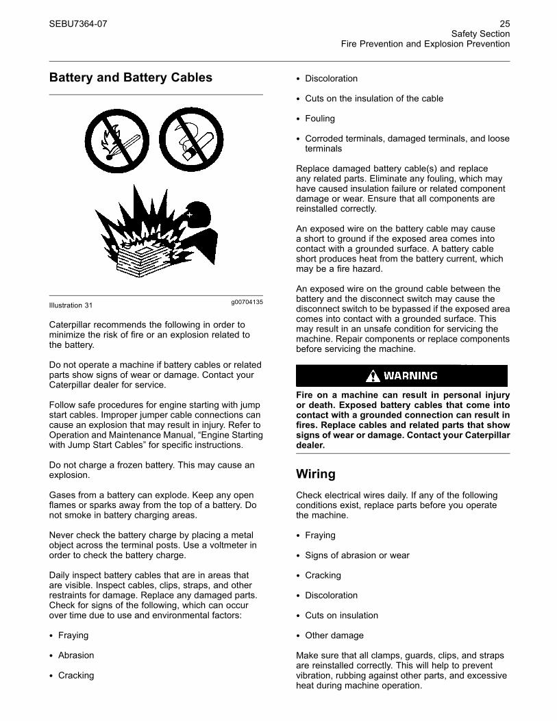
Store fuels and lubricants in properly markedcontainers away from unauthorized personnel. Storeoily rags and flammable materials in protectivecontainers. Do not smoke in areas that are used forstoring flammable materials.
g00704059Illustration 30
Use caution when you are fueling a machine. Do notsmoke while you are fueling a machine. Do not fuela machine near open flames or sparks. Always stopthe engine before fueling. Fill the fuel tank outdoors.Properly clean areas of spillage.
Follow practices for safe fueling that are describedin the “Operation” section of the Operation andMaintenance Manual section and follow localregulations. Never store flammable fluids in theoperator compartment of the machine.
SEBU7364-07 25Safety Section
Fire Prevention and Explosion Prevention
Battery and Battery Cables
g00704135Illustration 31
Caterpillar recommends the following in order tominimize the risk of fire or an explosion related tothe battery.
Do not operate a machine if battery cables or relatedparts show signs of wear or damage. Contact yourCaterpillar dealer for service.
Follow safe procedures for engine starting with jumpstart cables. Improper jumper cable connections cancause an explosion that may result in injury. Refer toOperation and Maintenance Manual, “Engine Startingwith Jump Start Cables” for specific instructions.
Do not charge a frozen battery. This may cause anexplosion.
Gases from a battery can explode. Keep any openflames or sparks away from the top of a battery. Donot smoke in battery charging areas.
Never check the battery charge by placing a metalobject across the terminal posts. Use a voltmeter inorder to check the battery charge.
Daily inspect battery cables that are in areas thatare visible. Inspect cables, clips, straps, and otherrestraints for damage. Replace any damaged parts.Check for signs of the following, which can occurover time due to use and environmental factors:
• Fraying
• Abrasion
• Cracking
• Discoloration
• Cuts on the insulation of the cable
• Fouling
• Corroded terminals, damaged terminals, and looseterminals
Replace damaged battery cable(s) and replaceany related parts. Eliminate any fouling, which mayhave caused insulation failure or related componentdamage or wear. Ensure that all components arereinstalled correctly.
An exposed wire on the battery cable may causea short to ground if the exposed area comes intocontact with a grounded surface. A battery cableshort produces heat from the battery current, whichmay be a fire hazard.
An exposed wire on the ground cable between thebattery and the disconnect switch may cause thedisconnect switch to be bypassed if the exposed areacomes into contact with a grounded surface. Thismay result in an unsafe condition for servicing themachine. Repair components or replace componentsbefore servicing the machine.
Fire on a machine can result in personal injuryor death. Exposed battery cables that come intocontact with a grounded connection can result infires. Replace cables and related parts that showsigns of wear or damage. Contact your Caterpillardealer.
WiringCheck electrical wires daily. If any of the followingconditions exist, replace parts before you operatethe machine.
• Fraying
• Signs of abrasion or wear
• Cracking
• Discoloration
• Cuts on insulation
• Other damage
Make sure that all clamps, guards, clips, and strapsare reinstalled correctly. This will help to preventvibration, rubbing against other parts, and excessiveheat during machine operation.
26 SEBU7364-07Safety SectionFire Prevention and Explosion Prevention
Attaching electrical wiring to hoses and tubes thatcontain flammable fluids or combustible fluids shouldbe avoided.
Consult your Caterpillar dealer for repair or forreplacement parts.
Keep wiring and electrical connections free of debris.
Lines, Tubes and HosesDo not bend high pressure lines. Do not strike highpressure lines. Do not install any lines that are bent ordamaged. Use the appropriate backup wrenches inorder to tighten all connections to the recommendedtorque.
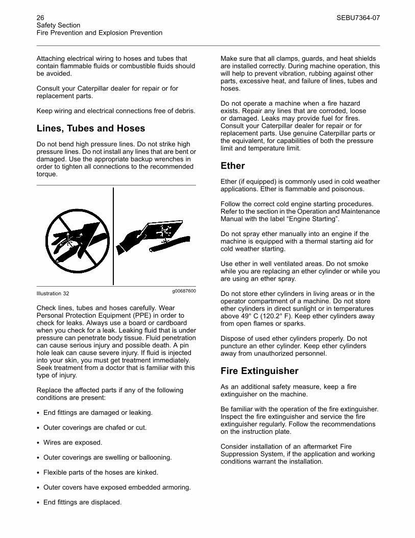
g00687600Illustration 32
Check lines, tubes and hoses carefully. WearPersonal Protection Equipment (PPE) in order tocheck for leaks. Always use a board or cardboardwhen you check for a leak. Leaking fluid that is underpressure can penetrate body tissue. Fluid penetrationcan cause serious injury and possible death. A pinhole leak can cause severe injury. If fluid is injectedinto your skin, you must get treatment immediately.Seek treatment from a doctor that is familiar with thistype of injury.
Replace the affected parts if any of the followingconditions are present:
• End fittings are damaged or leaking.
• Outer coverings are chafed or cut.
• Wires are exposed.
• Outer coverings are swelling or ballooning.
• Flexible parts of the hoses are kinked.
• Outer covers have exposed embedded armoring.
• End fittings are displaced.
Make sure that all clamps, guards, and heat shieldsare installed correctly. During machine operation, thiswill help to prevent vibration, rubbing against otherparts, excessive heat, and failure of lines, tubes andhoses.
Do not operate a machine when a fire hazardexists. Repair any lines that are corroded, looseor damaged. Leaks may provide fuel for fires.Consult your Caterpillar dealer for repair or forreplacement parts. Use genuine Caterpillar parts orthe equivalent, for capabilities of both the pressurelimit and temperature limit.
EtherEther (if equipped) is commonly used in cold weatherapplications. Ether is flammable and poisonous.
Follow the correct cold engine starting procedures.Refer to the section in the Operation and MaintenanceManual with the label “Engine Starting”.
Do not spray ether manually into an engine if themachine is equipped with a thermal starting aid forcold weather starting.
Use ether in well ventilated areas. Do not smokewhile you are replacing an ether cylinder or while youare using an ether spray.
Do not store ether cylinders in living areas or in theoperator compartment of a machine. Do not storeether cylinders in direct sunlight or in temperaturesabove 49° C (120.2° F). Keep ether cylinders awayfrom open flames or sparks.
Dispose of used ether cylinders properly. Do notpuncture an ether cylinder. Keep ether cylindersaway from unauthorized personnel.
Fire ExtinguisherAs an additional safety measure, keep a fireextinguisher on the machine.
Be familiar with the operation of the fire extinguisher.Inspect the fire extinguisher and service the fireextinguisher regularly. Follow the recommendationson the instruction plate.
Consider installation of an aftermarket FireSuppression System, if the application and workingconditions warrant the installation.
SEBU7364-07 27Safety Section
Fire Extinguisher Location
i01932259
Fire Extinguisher LocationSMCS Code: 7000; 7419
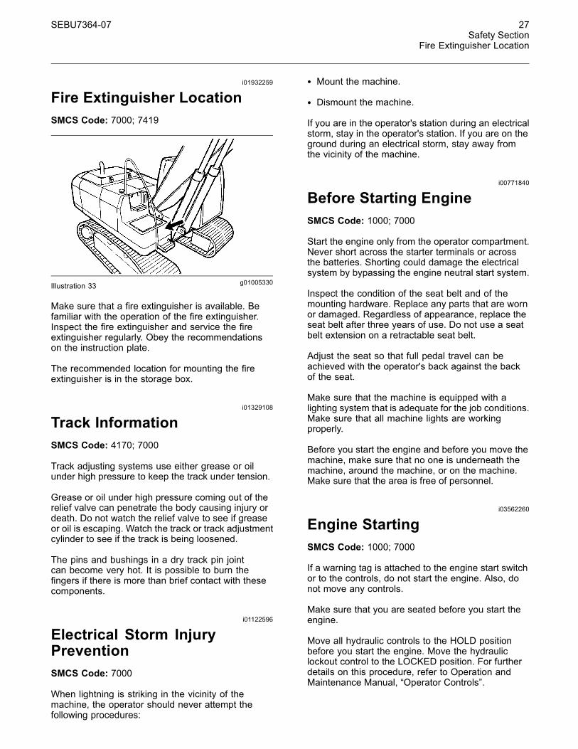
g01005330Illustration 33
Make sure that a fire extinguisher is available. Befamiliar with the operation of the fire extinguisher.Inspect the fire extinguisher and service the fireextinguisher regularly. Obey the recommendationson the instruction plate.
The recommended location for mounting the fireextinguisher is in the storage box.
i01329108
Track InformationSMCS Code: 4170; 7000
Track adjusting systems use either grease or oilunder high pressure to keep the track under tension.
Grease or oil under high pressure coming out of therelief valve can penetrate the body causing injury ordeath. Do not watch the relief valve to see if greaseor oil is escaping. Watch the track or track adjustmentcylinder to see if the track is being loosened.
The pins and bushings in a dry track pin jointcan become very hot. It is possible to burn thefingers if there is more than brief contact with thesecomponents.
i01122596
Electrical Storm InjuryPreventionSMCS Code: 7000
When lightning is striking in the vicinity of themachine, the operator should never attempt thefollowing procedures:
• Mount the machine.
• Dismount the machine.
If you are in the operator's station during an electricalstorm, stay in the operator's station. If you are on theground during an electrical storm, stay away fromthe vicinity of the machine.
i00771840
Before Starting EngineSMCS Code: 1000; 7000
Start the engine only from the operator compartment.Never short across the starter terminals or acrossthe batteries. Shorting could damage the electricalsystem by bypassing the engine neutral start system.
Inspect the condition of the seat belt and of themounting hardware. Replace any parts that are wornor damaged. Regardless of appearance, replace theseat belt after three years of use. Do not use a seatbelt extension on a retractable seat belt.
Adjust the seat so that full pedal travel can beachieved with the operator's back against the backof the seat.
Make sure that the machine is equipped with alighting system that is adequate for the job conditions.Make sure that all machine lights are workingproperly.
Before you start the engine and before you move themachine, make sure that no one is underneath themachine, around the machine, or on the machine.Make sure that the area is free of personnel.
i03562260
Engine StartingSMCS Code: 1000; 7000
If a warning tag is attached to the engine start switchor to the controls, do not start the engine. Also, donot move any controls.
Make sure that you are seated before you start theengine.
Move all hydraulic controls to the HOLD positionbefore you start the engine. Move the hydrauliclockout control to the LOCKED position. For furtherdetails on this procedure, refer to Operation andMaintenance Manual, “Operator Controls”.
28 SEBU7364-07Safety SectionBefore Operation
Diesel engine exhaust contains products ofcombustion which can be harmful to your health.Always run the engine in a well ventilated area. Ifyou are in an enclosed area, vent the exhaust to theoutside.
Briefly sound the horn before you start the engine.
i01340061
Before OperationSMCS Code: 7000
Clear all personnel from the machine and from thearea.
Clear all obstacles from the machine's path. Bewareof hazards (wires, ditches, etc).
Be sure that all windows are clean. Secure the doorsand the windows in the open position or in the shutposition.
Adjust the rearview mirrors (if equipped) for the bestvisibility close to the machine. Make sure that thehorn, the travel alarm (if equipped), and all otherwarning devices are working properly.
Fasten the seat belt securely.
Warm up the engine and the hydraulic oil beforeoperating the machine.
Before moving the machine, check the position of theundercarriage. The normal travel position is with theidler wheels to the front under the cab and the drivesprockets to the rear. When the undercarriage is inthe reversed position, the directional controls mustbe operated in opposite directions.
i03562303
Work ToolsSMCS Code: 6700
Only use work tools that are recommended byCaterpillar for use on Caterpillar machines.
Work tools and work tool control systems, thatare compatible with your Caterpillar machine, arerequired for safe machine operation and/or reliablemachine operation. If you are in doubt about thecompatibility of a particular work tool with yourmachine, consult your Caterpillar dealer.
Make sure that all necessary guarding is in place onthe host machine and on the work tool.
Keep all windows and doors closed on the hostmachine. A polycarbonate shield must be used whenthe host machine is not equipped with windows andwhen a work tool could throw debris.
Do not exceed the maximum operating weight that islisted on the ROPS certification.
If your machine is equipped with an extendable stick,install the transport pin when you are using thefollowing work tools: hydraulic hammers, augers, andcompactors
Always wear protective glasses. Always wear theprotective equipment that is recommended in thework tool's operation manual. Wear any otherprotective equipment that is required for the operatingenvironment.
To prevent personnel from being struck by flyingobjects, ensure that all personnel are out of the workarea.
While you are performing any maintenance, anytesting, or any adjustments to the work tool stayclear of the following areas: cutting edges, pinchingsurfaces, and crushing surfaces.
Never use the work tool for a work platform.
i03162317
Visibility InformationSMCS Code: 7000
Before you start the machine, perform a walk-aroundinspection in order to ensure that there are nohazards around the machine.
While the machine is in operation, constantly surveythe area around the machine in order to identifypotential hazards as hazards become visible aroundthe machine.
Your machine may be equipped with visual aids.Some examples of visual aids are Closed CircuitTelevision (CCTV) and mirrors. Before operating themachine, ensure that the visual aids are in properworking condition and that the visual aids are clean.Adjust the visual aids using the procedures that arelocated in this Operation and Maintenance Manual.If equipped, the Work Area Vision System shall beadjusted according to Operation and MaintenanceManual, SEBU8157, “Work Area Vision System”.
SEBU7364-07 29Safety Section
Operation
It may not be possible to provide direct visibility onlarge machines to all areas around the machine.Appropriate job site organization is required in orderto minimize hazards that are caused by restrictedvisibility. Job site organization is a collection of rulesand procedures that coordinates machines andpeople that work together in the same area. Examplesof job site organization include the following:
• Safety instructions
• Controlled patterns of machine movement andvehicle movement
• Workers that direct traffic to move when it is safe
• Restricted areas
• Operator training
• Warning symbols or warning signs on machinesor on vehicles
• A system of communication
• Communication between workers and operatorsprior to approaching the machine
Modifications of the machine configuration by theuser that result in a restriction of visibility shall beevaluated.
i03562320
OperationSMCS Code: 7000
Machine Operating TemperatureRangeThe machine must function satisfactorily in theanticipated ambient temperature limits that areencountered during operation. The standard machineconfiguration is intended for use within an ambienttemperature range of −20 °C (−4 °F) to 43 °C(109 °F). Special configurations for different ambienttemperatures may be available. Consult yourCaterpillar dealer for additional information on specialconfigurations of your machine.
Machine OperationOnly operate the machine while you are in a seat.The seat belt must be fastened while you operate themachine. Only operate the controls while the engineis running.
Check for proper operation of all controls and of allprotective devices while you operate the machineslowly in an open area.
When the machine is moving watch the clearanceof the boom. Uneven ground can cause the boomto move in all directions.
Make sure that no personnel will be endangeredbefore you move the machine. Do not allow riders onthe machine unless the machine has an additionalseat with a seat belt.
Report any machine damage that was noted duringmachine operation. Make any necessary repairs.
Never use the work tool for a work platform.
Hold attachments approximately 40 cm (15 inches)above ground level while you drive the machine. Donot drive the machine close to an overhang, to theedge of a cliff, or to the edge of an excavation.
If the machine begins to sideslip on a grade,immediately dump the load and turn the machinedownhill.
Be careful to avoid any ground condition which couldcause the machine to tip. Tipping can occur whenyou work on hills, on banks, or on slopes. Tipping canalso occur when you cross ditches, ridges, or otherunexpected obstructions.
When possible, operate the machine up slopes anddown slopes. Avoid operating the machine acrossthe slope.
Keep the machine under control. Do not overload themachine beyond capacity.
Avoid changing the direction of travel on a slope. Thiscould result in tipping or side slipping of the machine.
Bring the load close to the machine before travellingany distances.
Bring the load close to the machine before swingingthe load.
Lifting capacity decreases as the load is movedfurther from the machine.
Make sure that the towing eyes and the towingdevices are adequate for your needs.
Only connect trailing equipment to a drawbar or to ahitch.
Never straddle a wire cable. Never allow otherpersonnel to straddle a wire cable.
30 SEBU7364-07Safety SectionLifting Objects
When you maneuver in order to connect theequipment, make sure that no personnel are betweenthe machine and trailing equipment. Block up thehitch of the trailing equipment in order to align theequipment with the drawbar.
Check the local regulations, state codes, and/ordirectives of the job site for a specific minimumdistance from obstacles.
Before you operate the machine, check with localutilities for the locations of underground pipes and forthe locations of buried cables.
Know the maximum dimensions of your machine.
Watch the load at all times.
Do not operate the machine without thecounterweight. The machine can tip when the boomis over the side.
The clamshell, the grapple, or the magnet can swingin all directions. Move the joysticks in a continuousmotion. Failure to move the joysticks in a continuousmotion can cause the clamshell, the grapple, or themagnet to swing into the cab or into a person in thework area. This will result in personal injury.
The boom and the stick linkage can allow the worktool to contact the undercarriage and/or the cab. Beaware of the position of the work tool.
i03465380
Lifting ObjectsSMCS Code: 7000
There may be some local regulations and/orgovernment regulations that govern the use ofexcavators which lift heavy objects. Obey thoseregulations.
If this machine is used to lift objects within anarea that is controlled by the European Directive“98/37/EC”, the machine must be equipped with aboom lowering control valve and an overload warningdevice.
i02252108
ParkingSMCS Code: 7000
The hydraulic system remains pressurized providedthat the accumulator is charged. This condition is trueeven when the engine is not running. This pressureshould decrease in a short time (approximatelyone minute). While the hydraulic system maintainsa charge, the hydraulic work tools and machinecontrols remain functional.
Machine movement that is sudden and unexpectedwill occur if any of the controls are moved. This cancause personal injury or death.
Always move the hydraulic lockout control to theLOCKED position before you shut off the engine orimmediately after the engine stops running.
Park the machine on a level surface. If you mustpark the machine on a grade, chock the tracks of themachine.
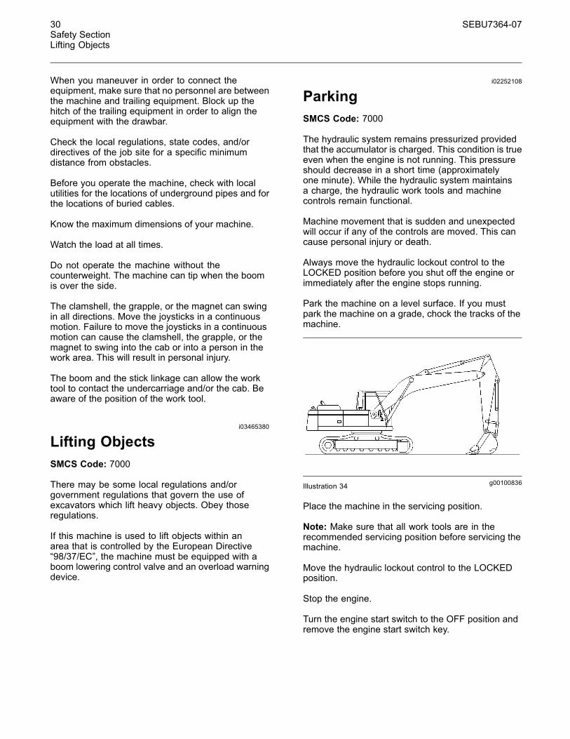
g00100836Illustration 34
Place the machine in the servicing position.
Note: Make sure that all work tools are in therecommended servicing position before servicing themachine.
Move the hydraulic lockout control to the LOCKEDposition.
Stop the engine.
Turn the engine start switch to the OFF position andremove the engine start switch key.
SEBU7364-07 31Safety Section
Slope Operation
Turn the battery disconnect switch to the OFFposition. Remove the disconnect switch key if youdo not operate the machine for an extended periodof time. This will prevent drainage of the battery. Abattery short circuit, any current draw from certaincomponents, and vandalism can cause drainage ofthe battery.
i03745198
Slope OperationSMCS Code: 7000
Machines that are operating safely in variousapplications depend on these criteria: the machinemodel, configuration, machine maintenance,operating speed of the machine, conditions of theterrain, fluid levels, and tire inflation pressures. Themost important criteria are the skill and judgment ofthe operator.
A well trained operator that follows the instructionsin the Operation and Maintenance Manual hasthe greatest impact on stability. Operator trainingprovides a person with the following abilities:observation of working and environmental conditions,feel for the machine, identification of potentialhazards, and operating the machine safely by makingappropriate decisions.
When you work on side hills and when you work onslopes, consider the following important points:
Speed of travel – At higher speeds, forces of inertiatend to make the machine less stable.
Roughness of terrain or surface – The machinemay be less stable with uneven terrain.
Direction of travel – Avoid operating the machineacross the slope. When possible, operate themachine up the slopes and operate the machinedown the slopes. Place the heaviest end of themachine uphill when you are working on an incline.
Mounted equipment – Balance of the machinemay be impeded by the following components:equipment that is mounted on the machine, machineconfiguration, weights, and counterweights.
Nature of surface – Ground that has been newlyfilled with earth may collapse from the weight of themachine.
Surface material – Rocks and moisture of thesurface material may drastically affect the machine'straction and machine's stability. Rocky surfaces maypromote side slipping of the machine.
Slippage due to excessive loads – This may causedownhill tracks or downhill tires to dig into the ground,which will increase the angle of the machine.
Width of tracks or tires – Narrower tracks ornarrower tires further increase the digging into theground which causes the machine to be less stable.
Implements attached to the drawbar – This maydecrease the weight on the uphill tracks. This mayalso decrease the weight on the uphill tires. Thedecreased weight will cause the machine to be lessstable.
Height of the working load of the machine –When the working loads are in higher positions, thestability of the machine is reduced.
Operated equipment – Be aware of performancefeatures of the equipment in operation and the effectson machine stability.
Operating techniques – Keep all attachments orpulled loads low to the ground for optimum stability.
Machine systems have limitations on slopes –Slopes can affect the proper function and operationof the various machine systems. These machinesystems are needed for machine control.
Note: Safe operation on steep slopes may requirespecial machine maintenance. Excellent skill ofthe operator and proper equipment for specificapplications are also required. Consult the Operationand Maintenance Manual sections for the proper fluidlevel requirements and intended machine use.
i01329161
Equipment Lowering withEngine StoppedSMCS Code: 7000-II
Before lowering any equipment with the enginestopped, clear the area around the equipment ofall personnel. The procedure to use will vary withthe type of equipment to be lowered. Keep in mindmost systems use a high pressure fluid or air toraise or lower equipment. The procedure will causehigh pressure air, hydraulic, or some other mediato be released in order to lower the equipment.Wear appropriate personal protective equipment andfollow the established procedure in the Operationand Maintenance Manual, “Equipment Lowering withEngine Stopped” in the Operation Section of themanual.

32 SEBU7364-07Safety SectionSound Information and Vibration Information
i03671777
Sound Information andVibration InformationSMCS Code: 7000
Sound Level InformationHearing protection may be needed when themachine is operated with an open operator station forextended periods or in a noisy environment. Hearingprotection may be needed when the machine isoperated with a cab that is not properly maintained, orwhen the doors and windows are open for extendedperiods or in a noisy environment.
Sound Level Information forMachines in European UnionCountries and in Countries thatAdopt the “EU Directives”The dynamic operator sound pressure level is 76dB(A) when “ISO6396” is used to measure the valuefor an enclosed cab. The cab was properly installedand maintained. The test was conducted with the cabdoors and the cab windows closed.
The average exterior sound pressure level is 102dB(A) when the “ISO6395-Dynamic Test” procedureis used to measure the value for the standardmachine.
“The European Union PhysicalAgents (Vibration) Directive2002/44/EC”
Vibration Data for Track Type Excavator
Information Concerning Hand/Arm VibrationLevel
When the machine is operated according to theintended use, the hand/arm vibration of this machineis below 2.5 meter per second squared.
Information Concerning Whole Body VibrationLevel
This section provides vibration data and a methodfor estimating the vibration level for track typeexcavators.
Note: Vibration levels are influenced by manydifferent parameters. Many items are listed below.
• Operator training, behavior, mode, and stress
• Job site organization, preparation, environment,weather, and material
• Machine type, quality of the seat, quality of thesuspension system, attachments, and condition ofthe equipment
It is not possible to get precise vibration levels forthis machine. The expected vibration levels can beestimated with the information in Table 1 in orderto calculate the daily vibration exposure. A simpleevaluation of the machine application can be used.
Estimate the vibration levels for the three vibrationdirections. For typical operating conditions, use theaverage vibration levels as the estimated level. Withan experienced operator and smooth terrain, subtractthe Scenario Factors from the average vibration levelin order to obtain the estimated vibration level. Foraggressive operations and severe terrain, add theScenario Factors to the average vibration level inorder to obtain the estimated vibration level.
Note: All vibration levels are in meter per secondsquared.
SEBU7364-07 33Safety Section
Sound Information and Vibration Information
Table 1
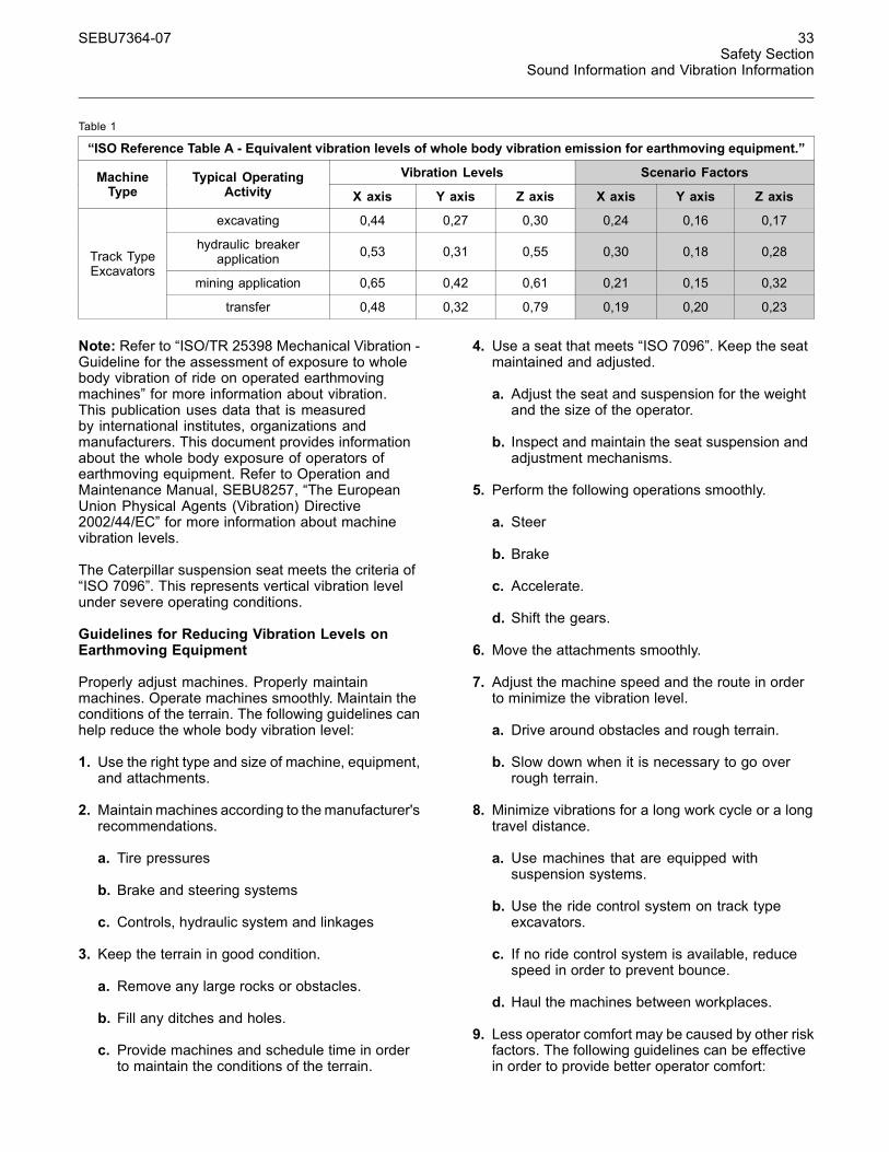
“ISO Reference Table A - Equivalent vibration levels of whole body vibration emission for earthmoving equipment.”
Vibration Levels Scenario FactorsMachineType
Typical OperatingActivity X axis Y axis Z axis X axis Y axis Z axis
excavating 0,44 0,27 0,30 0,24 0,16 0,17
hydraulic breakerapplication 0,53 0,31 0,55 0,30 0,18 0,28
mining application 0,65 0,42 0,61 0,21 0,15 0,32
Track TypeExcavators
transfer 0,48 0,32 0,79 0,19 0,20 0,23
Note: Refer to “ISO/TR 25398 Mechanical Vibration -Guideline for the assessment of exposure to wholebody vibration of ride on operated earthmovingmachines” for more information about vibration.This publication uses data that is measuredby international institutes, organizations andmanufacturers. This document provides informationabout the whole body exposure of operators ofearthmoving equipment. Refer to Operation andMaintenance Manual, SEBU8257, “The EuropeanUnion Physical Agents (Vibration) Directive2002/44/EC” for more information about machinevibration levels.
The Caterpillar suspension seat meets the criteria of“ISO 7096”. This represents vertical vibration levelunder severe operating conditions.
Guidelines for Reducing Vibration Levels onEarthmoving Equipment
Properly adjust machines. Properly maintainmachines. Operate machines smoothly. Maintain theconditions of the terrain. The following guidelines canhelp reduce the whole body vibration level:
1. Use the right type and size of machine, equipment,and attachments.
2. Maintainmachines according to themanufacturer'srecommendations.
a. Tire pressures
b. Brake and steering systems
c. Controls, hydraulic system and linkages
3. Keep the terrain in good condition.
a. Remove any large rocks or obstacles.
b. Fill any ditches and holes.
c. Provide machines and schedule time in orderto maintain the conditions of the terrain.
4. Use a seat that meets “ISO 7096”. Keep the seatmaintained and adjusted.
a. Adjust the seat and suspension for the weightand the size of the operator.
b. Inspect and maintain the seat suspension andadjustment mechanisms.
5. Perform the following operations smoothly.
a. Steer
b. Brake
c. Accelerate.
d. Shift the gears.
6. Move the attachments smoothly.
7. Adjust the machine speed and the route in orderto minimize the vibration level.
a. Drive around obstacles and rough terrain.
b. Slow down when it is necessary to go overrough terrain.
8. Minimize vibrations for a long work cycle or a longtravel distance.
a. Use machines that are equipped withsuspension systems.
b. Use the ride control system on track typeexcavators.
c. If no ride control system is available, reducespeed in order to prevent bounce.
d. Haul the machines between workplaces.
9. Less operator comfort may be caused by other riskfactors. The following guidelines can be effectivein order to provide better operator comfort:
34 SEBU7364-07Safety SectionGuards
a. Adjust the seat and adjust the controls in orderto achieve good posture.
b. Adjust the mirrors in order to minimize twistedposture.
c. Provide breaks in order to reduce long periodsof sitting.
d. Avoid jumping from the cab.
e. Minimize repeated handling of loads and liftingof loads.
f. Minimize any shocks and impacts during sportsand leisure activities.
SourcesThe vibration information and the calculationprocedure is based on “ISO/TR 25398 MechanicalVibration - Guideline for the assessment of exposureto whole body vibration of ride on operatedearthmoving machines”. Harmonized data ismeasured by international institutes, organizationsand manufacturers.
This literature provides information about assessingthe whole body vibration exposure of operators ofearthmoving equipment. The method is based onmeasured vibration emission under real workingconditions for all machines.
You should check the original directive. Thisdocument summarizes part of the content of theapplicable law. This document is not meant tosubstitute the original sources. Other parts of thesedocuments are based on information from the UnitedKingdom Health and Safety Executive.
Refer to Operation and Maintenance Manual,SEBU8257, “The European Union PhysicalAgents (Vibration) Directive 2002/44/EC” for moreinformation about vibration.
Consult your local Caterpillar dealer for moreinformation about machine features that minimizevibration levels. Consult your local Caterpillar dealerabout safe machine operation.
Use the following web site in order to find your localdealer:
Caterpillar, Inc.www.cat.com
i03656846
Guards(Operator Protection)SMCS Code: 7000; 7150
There are different types of guards that are used toprotect the operator. The machine and the machineapplication determines the type of guard that shouldbe used.
A daily inspection of the guards is required in order tocheck for structures that are bent, cracked or loose.Never operate a machine with a damaged structure.
The operator becomes exposed to a hazardoussituation if the machine is used improperly or if pooroperating techniques are used. This situation canoccur even though a machine is equipped with anappropriate protective guard. Follow the establishedoperating procedures that are recommended for yourmachine.
Rollover Protective Structure(ROPS), Falling Object ProtectiveStructure (FOPS) or Tip OverProtection Structure (TOPS)The ROPS/FOPS Structure (if equipped) on yourmachine is specifically designed, tested andcertified for that machine. Any alteration or anymodification to the ROPS/FOPS Structure couldweaken the structure. This places the operatorinto an unprotected environment. Modifications orattachments that cause the machine to exceed theweight that is stamped on the certification plate alsoplace the operator into an unprotected environment.Excessive weight may inhibit the brake performance,the steering performance and the ROPS. Theprotection that is offered by the ROPS/FOPSStructure will be impaired if the ROPS/FOPSStructure has structural damage. Damage to thestructure can be caused by an overturn, a fallingobject, a collision, etc.
Do not mount items (fire extinguishers, first aidkits, work lights, etc) by welding brackets to theROPS/FOPS Structure or by drilling holes in theROPS/FOPS Structure. Welding brackets or drillingholes in the ROPS/FOPS Structures can weakenthe structures. Consult your Caterpillar dealer formounting guidelines.
SEBU7364-07 35Safety Section
Guards
The Tip Over Protection Structure (TOPS) isanother type of guard that is used on mini hydraulicexcavators. This structure protects the operator inthe event of a tipover. The same guidelines for theinspection, the maintenance and the modification ofthe ROPS/FOPS Structure are required for the TipOver Protection Structure.
Other Guards (If Equipped)Protection from flying objects and/or falling objects isrequired for special applications. Logging applicationsand demolition applications are two examples thatrequire special protection.
A front guard needs to be installed when a work toolthat creates flying objects is used. Mesh front guardsthat are approved by Caterpillar or polycarbonatefront guards that are approved by Caterpillar areavailable for machines with a cab or an open canopy.On machines that are equipped with cabs, thewindows should also be closed. Safety glasses arerecommended when flying hazards exist for machineswith cabs and machines with open canopies.
If the work material extends above the cab, topguards and front guards should be used. Typicalexamples of this type of application are listed below:
• Demolition applications
• Rock quarries
• Forestry products
Additional guards may be required for specificapplications or work tools. The Operation andMaintenance Manual for your machine or yourwork tool will provide specific requirements for theguards. Consult your Caterpillar dealer for additionalinformation.