Embed Size (px)
Citation preview
CAT Advanced series
Circuit Breaker Analyzers & Timers
• Robust design for field use
• Accurate measurement in high voltage environment
• Both Sides Grounded feature for AIS and GIS (optional)
• Built-in micro ohmmeter (up to 500 A)
• Dynamic resistance measurement
• Detailed analysis of test results using DV-Win software
• Database of circuit breakers test plans
Description
The CAT Advanced series circuit breaker
analyzers & timers are stand-alone or a PC-
controlled digital instruments for circuit breakers
condition assessments. CAT Advanced series
records graphs of both, open and close coil
currents and displacements of the HV and MV
circuit breaker moving parts.
The timing channels record closing and
opening of the arcing, resistor and auxiliary
contacts. The main contact channels can also
measure the resistance value of the pre-insertion
resistors (if present in the circuit breaker).
Furthermore, the main contact timing channels
can also measure main arcing contacts operation
time of AIS (Air Insulated Substation) circuit
breakers with both sides grounded (BSG).
CAT Advanced series provides an easy selection
of different operational modes:
• Open (O)
• Close (C)
• Reclose (O-0,3s-C)
• Trip free (CO)
• O-0,3s-CO
• Open-Close (O-C)
• Close-Open (C-O)
• Open-Close-Open (O-C-O)
• First trip (O)
Multiple operations, such as Open-Close and
Open-Close-Open, can be initiated by using a
predefined delay time or by sensing a breaker’s
contact position.
The circuit breaker operation can be initiated in
different ways (for instance from a control room,
by a local switch or externally by a testing
device) depending on a testing condition. The
several time measurement triggers are available
to record a measurement in a various testing
condition:
• external trigger
• analog channels
• auxiliary channels
• coil control channel
The auxiliary inputs are used to monitor dry and
wet auxiliary contacts. The six coil control analog
channels can measure and record coil currents
simultaneously (OPEN and CLOSE), up to 35 A
AC/DC.
Built-in micro-ohmmeter provides high current
for dynamic and static resistance measurement,
as well as for BSG timing measurement of GIS
(Gas Insulated Substation) and Dead tank AIS
(Air Insulated Substation) circuit breakers.

B-C
AT
AD
V-1
15-E
N, 2
021
-09-2
1
2 CAT Advanced series Circuit Breaker Analyzers & Timer
The additional six voltage analog channels have
four selectable voltage ranges available (±1 V,
±5 V, ±60 V and ±300 V AC/DC). They are used to
monitor:
• Measurement of coil resistance (simultaneously
for 3 coils – during open or close sequence)
• Circuit-breaker substation battery voltage,
• DC and AC currents during the “First trip” test,
• CT secondary currents for BSG test on GIS
• Other types of analog signals that may be
relevant.
Three transducer channels provide measuring
displacement of the circuit breaker moving parts,
contact wipe, over-travel, rebound, damping time
and an average velocity. Either an analog or a
digital transducer can be connected to these
universal channels.
Test results are printed on the 112 mm (4.4 inch)
thermal printer (optional accessory) in tabular
and graphical form.
Application
The list of the instrument applications includes:
• Simultaneous timing measurement of up to 12 main contacts (4 breaks per phase) including
pre-insertion resistors (if present in the circuit breaker) and 6 auxiliary contacts
• Resistance measurement of the pre-insertion resistors (if present in the circuit breaker)
• Evaluation of synchronization between the circuit breaker poles
• Measurement of the coil currents, voltages and resistance simultaneously for 6 coils
• Evaluating the state of substation’s batteries by graphically showing the voltage value
• Measurement of displacement, contact wipe, over-travel, rebound, damping time and average
velocity of the breaker’s moving parts
• Anti-pumping relay test
• “First trip” test
• Static resistance measurement
• Dynamic resistance measurement
• Minimum operating voltage test (when used as CAT & SAT test system)
• Measurement of spring-charging motor time, current and voltage (both DC and AC power supply
voltage, when used as CAT & SAT test system)
B-C
AT
AD
V-1
15-E
N, 2
021
-09-2
1
3 CAT Advanced series Circuit Breaker Analyzers & Timer
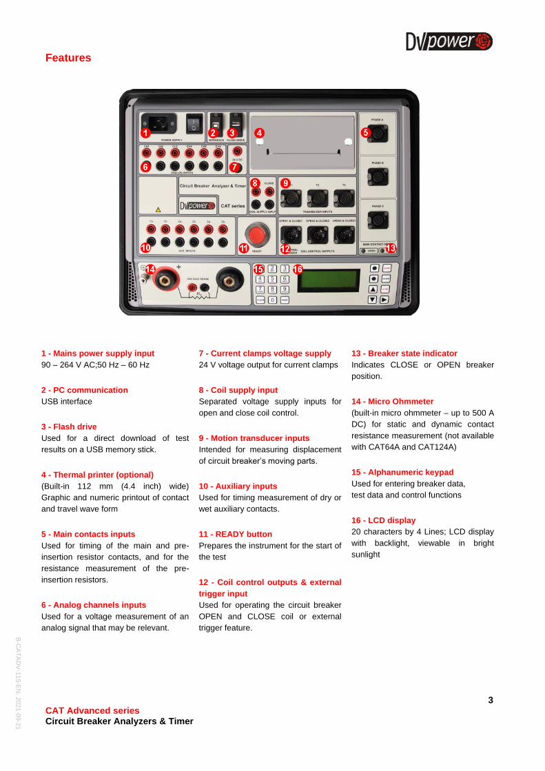
Features
1 - Mains power supply input
90 – 264 V AC;50 Hz – 60 Hz
2 - PC communication
USB interface
3 - Flash drive
Used for a direct download of test
results on a USB memory stick.
4 - Thermal printer (optional)
(Built-in 112 mm (4.4 inch) wide)
Graphic and numeric printout of contact
and travel wave form
5 - Main contacts inputs
Used for timing of the main and pre-
insertion resistor contacts, and for the
resistance measurement of the pre-
insertion resistors.
6 - Analog channels inputs
Used for a voltage measurement of an
analog signal that may be relevant.
7 - Current clamps voltage supply
24 V voltage output for current clamps
8 - Coil supply input
Separated voltage supply inputs for
open and close coil control.
9 - Motion transducer inputs
Intended for measuring displacement
of circuit breaker’s moving parts.
10 - Auxiliary inputs
Used for timing measurement of dry or
wet auxiliary contacts.
11 - READY button
Prepares the instrument for the start of
the test
12 - Coil control outputs & external
trigger input
Used for operating the circuit breaker
OPEN and CLOSE coil or external
trigger feature.
13 - Breaker state indicator
Indicates CLOSE or OPEN breaker
position.
14 - Micro Ohmmeter
(built-in micro ohmmeter – up to 500 A
DC) for static and dynamic contact
resistance measurement (not available
with CAT64A and CAT124A)
15 - Alphanumeric keypad
Used for entering breaker data,
test data and control functions
16 - LCD display
20 characters by 4 Lines; LCD display
with backlight, viewable in bright
sunlight
B-C
AT
AD
V-1
15-E
N, 2
021
-09-2
1
4 CAT Advanced series Circuit Breaker Analyzers & Timer
Timing measurement
Timing measurement of the mechanical
operations is one of the most important tests to
determine real condition of the circuit breaker.
Timing measurement tests fulfill all the
requirements defined by IEC 62271-100 and
IEEE C37.09.
In three-phase systems, not only the contacts in
a single pole have to operate simultaneously,
but all poles must also operate at the same time.
All contacts must be synchronized, within a
certain tolerance limit.
Synchronization between the circuit breaker
poles during opening shall not exceed 1/6 of the
rated frequency cycle (3,33 ms at 50 Hz; 2,78
ms at 60 Hz) and during closing shall not exceed
1/4 of the rated frequency cycle, as well (5,0 ms
at 50 Hz; 4,17 ms at 60 Hz).
Simultaneous measurements within a single
phase are important in situations where a
number of contacts are connected in series.
The maximum difference between the instants of
contact separation within series connected
interrupter units shall not exceed 1/8 of a cycle
of rated frequency (2,50 ms at 50 Hz; 2,08 ms at
60 Hz). Maximum difference between the
instants of contacts touching within series
connected interrupter units shall not exceed a
1/6 of a cycle of rated frequency (3,33 ms at 50
Hz; 2,78 ms at 60 Hz).
Auxiliary contacts are mechanically driven by the
operating mechanism and are used for control
and indication of main contacts state. There are
no general requirements, related to timing
measurement of auxiliary contacts, described in
IEC® and IEEE® standards. Anyway, in order to
assess condition of high-voltage circuit breakers,
it is important to check their operation.
Type "a" contact follows circuit breaker main
contact position and must close/open ahead of
the closing/opening of the main contact. Type
"a" contact is connected in series with the open
coil and interrupts the open coil circuit when the
circuit breaker opens.
The "b" contact must open/close when the
operating mechanism has released its stored
energy in order to close/open the breaker. Type
"b" contact is connected in series with the
closing coil, interrupting the closing coil circuit
when the circuit breaker closes.
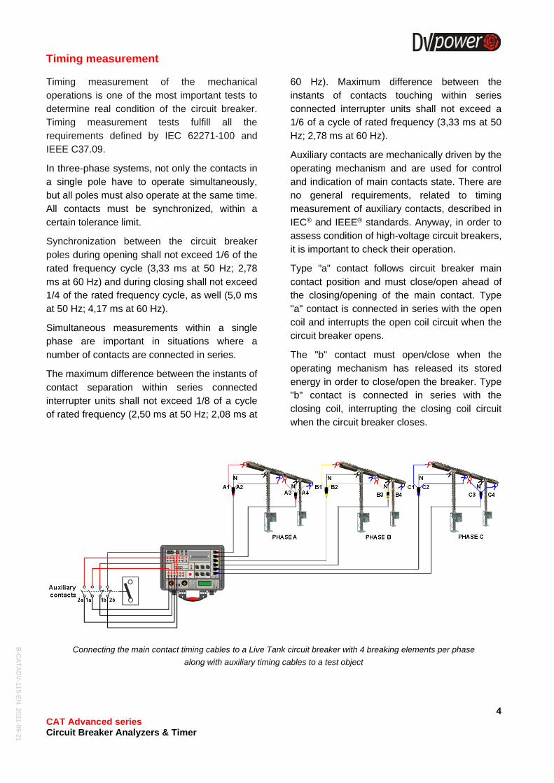
Connecting the main contact timing cables to a Live Tank circuit breaker with 4 breaking elements per phase
along with auxiliary timing cables to a test object
B-C
AT
AD
V-1
15-E
N, 2
021
-09-2
1
5 CAT Advanced series Circuit Breaker Analyzers & Timer
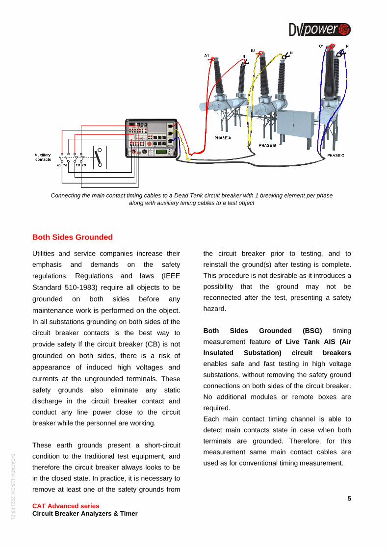
Connecting the main contact timing cables to a Dead Tank circuit breaker with 1 breaking element per phase
along with auxiliary timing cables to a test object
Both Sides Grounded
Utilities and service companies increase their
emphasis and demands on the safety
regulations. Regulations and laws (IEEE
Standard 510-1983) require all objects to be
grounded on both sides before any
maintenance work is performed on the object.
In all substations grounding on both sides of the
circuit breaker contacts is the best way to
provide safety If the circuit breaker (CB) is not
grounded on both sides, there is a risk of
appearance of induced high voltages and
currents at the ungrounded terminals. These
safety grounds also eliminate any static
discharge in the circuit breaker contact and
conduct any line power close to the circuit
breaker while the personnel are working.
These earth grounds present a short-circuit
condition to the traditional test equipment, and
therefore the circuit breaker always looks to be
in the closed state. In practice, it is necessary to
remove at least one of the safety grounds from
the circuit breaker prior to testing, and to
reinstall the ground(s) after testing is complete.
This procedure is not desirable as it introduces a
possibility that the ground may not be
reconnected after the test, presenting a safety
hazard.
Both Sides Grounded (BSG) timing
measurement feature of Live Tank AIS (Air
Insulated Substation) circuit breakers
enables safe and fast testing in high voltage
substations, without removing the safety ground
connections on both sides of the circuit breaker.
No additional modules or remote boxes are
required.
Each main contact timing channel is able to
detect main contacts state in case when both
terminals are grounded. Therefore, for this
measurement same main contact cables are
used as for conventional timing measurement.
B-C
AT
AD
V-1
15-E
N, 2
021
-09-2
1
6 CAT Advanced series Circuit Breaker Analyzers & Timer
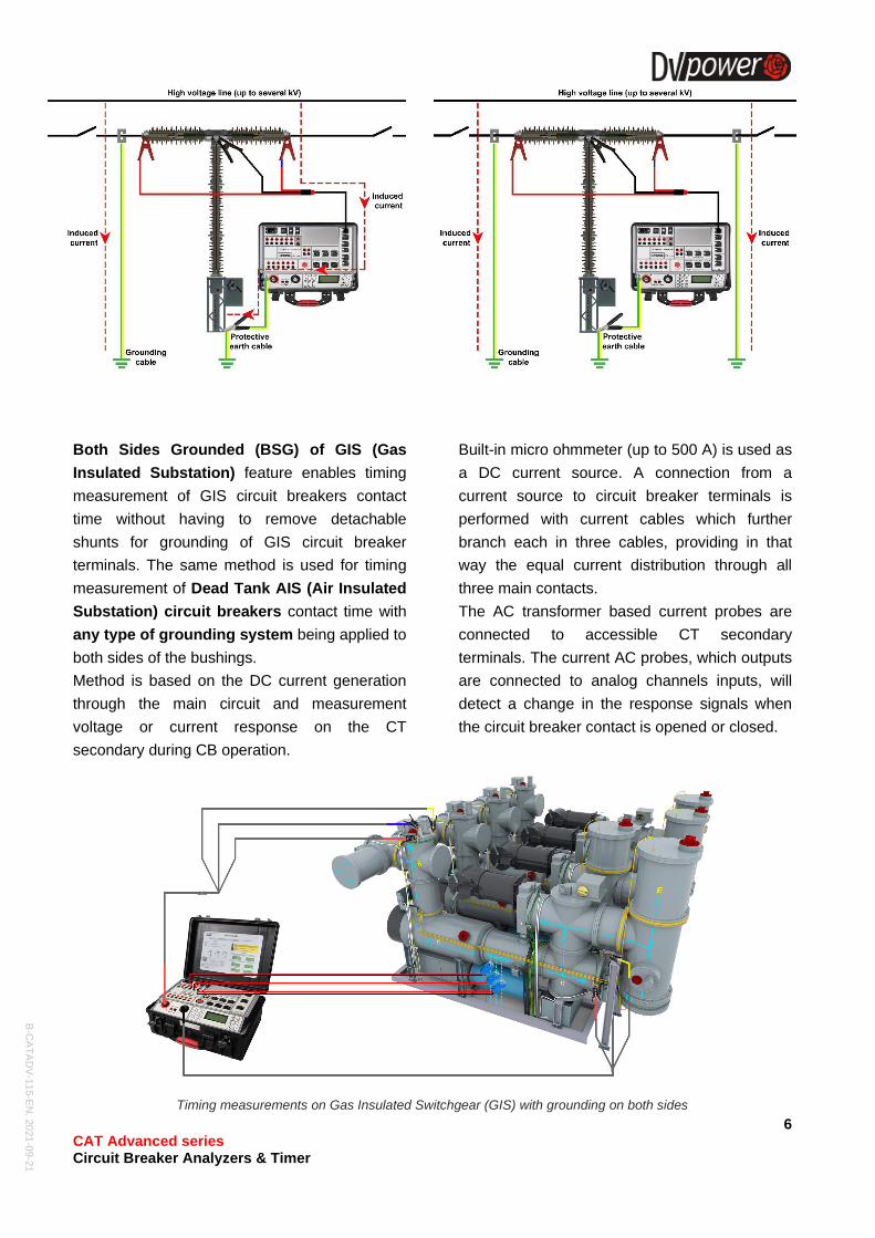
Both Sides Grounded (BSG) of GIS (Gas
Insulated Substation) feature enables timing
measurement of GIS circuit breakers contact
time without having to remove detachable
shunts for grounding of GIS circuit breaker
terminals. The same method is used for timing
measurement of Dead Tank AIS (Air Insulated
Substation) circuit breakers contact time with
any type of grounding system being applied to
both sides of the bushings.
Method is based on the DC current generation
through the main circuit and measurement
voltage or current response on the CT
secondary during CB operation.
Built-in micro ohmmeter (up to 500 A) is used as
a DC current source. A connection from a
current source to circuit breaker terminals is
performed with current cables which further
branch each in three cables, providing in that
way the equal current distribution through all
three main contacts.
The AC transformer based current probes are
connected to accessible CT secondary
terminals. The current AC probes, which outputs
are connected to analog channels inputs, will
detect a change in the response signals when
the circuit breaker contact is opened or closed.
Timing measurements on Gas Insulated Switchgear (GIS) with grounding on both sides
B-C
AT
AD
V-1
15-E
N, 2
021
-09-2
1
7 CAT Advanced series Circuit Breaker Analyzers & Timer
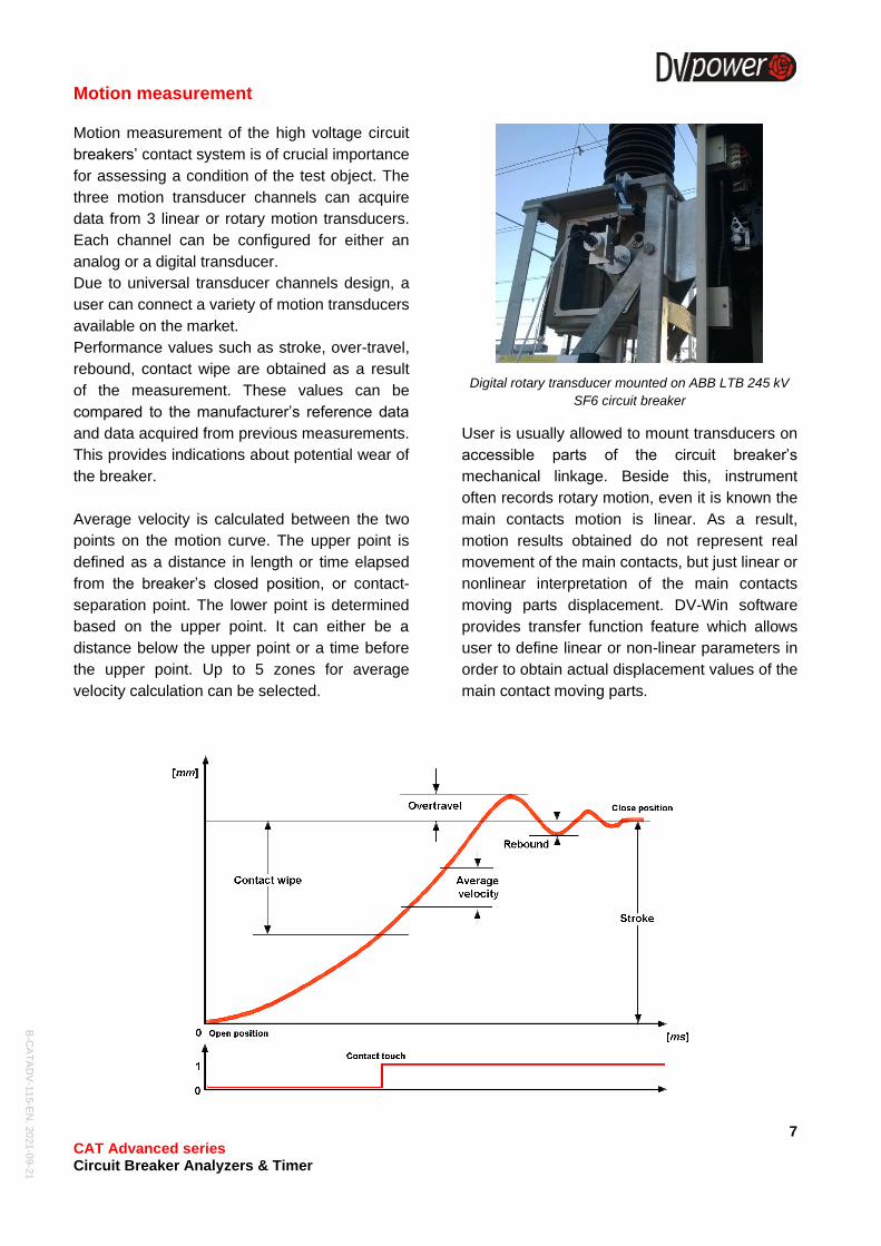
Motion measurement
Motion measurement of the high voltage circuit
breakers’ contact system is of crucial importance
for assessing a condition of the test object. The
three motion transducer channels can acquire
data from 3 linear or rotary motion transducers.
Each channel can be configured for either an
analog or a digital transducer.
Due to universal transducer channels design, a
user can connect a variety of motion transducers
available on the market.
Performance values such as stroke, over-travel,
rebound, contact wipe are obtained as a result
of the measurement. These values can be
compared to the manufacturer’s reference data
and data acquired from previous measurements.
This provides indications about potential wear of
the breaker.
Average velocity is calculated between the two
points on the motion curve. The upper point is
defined as a distance in length or time elapsed
from the breaker’s closed position, or contact-
separation point. The lower point is determined
based on the upper point. It can either be a
distance below the upper point or a time before
the upper point. Up to 5 zones for average
velocity calculation can be selected.
Digital rotary transducer mounted on ABB LTB 245 kV
SF6 circuit breaker
User is usually allowed to mount transducers on
accessible parts of the circuit breaker’s
mechanical linkage. Beside this, instrument
often records rotary motion, even it is known the
main contacts motion is linear. As a result,
motion results obtained do not represent real
movement of the main contacts, but just linear or
nonlinear interpretation of the main contacts
moving parts displacement. DV-Win software
provides transfer function feature which allows
user to define linear or non-linear parameters in
order to obtain actual displacement values of the
main contact moving parts.
B-C
AT
AD
V-1
15-E
N, 2
021
-09-2
1
8 CAT Advanced series Circuit Breaker Analyzers & Timer
Coil current measurement
The IEC 62271-100 standard states that it is
desirable to record the coil currents waveform,
since it provides information about coils’
condition (e.g. increased friction of the plungers,
burned insulation, short-circuited part of the
winding), the latch for release of the operating
mechanism (e.g. increased friction) and the
operating mechanism (e.g. if there is reduced
operating mechanism speed that can be seen
based on the opening time of auxiliary contacts).
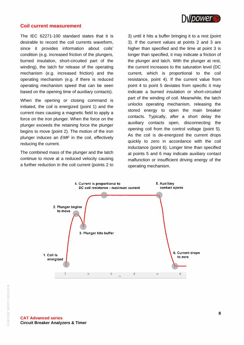
When the opening or closing command is
initiated, the coil is energized (point 1) and the
current rises causing a magnetic field to apply a
force on the iron plunger. When the force on the
plunger exceeds the retaining force the plunger
begins to move (point 2). The motion of the iron
plunger induces an EMF in the coil, effectively
reducing the current.
The combined mass of the plunger and the latch
continue to move at a reduced velocity causing
a further reduction in the coil current (points 2 to
3) until it hits a buffer bringing it to a rest (point
3). If the current values at points 2 and 3 are
higher than specified and the time at point 3 is
longer than specified, it may indicate a friction of
the plunger and latch. With the plunger at rest,
the current increases to the saturation level (DC
current, which is proportional to the coil
resistance, point 4). If the current value from
point 4 to point 5 deviates from specific it may
indicate a burned insulation or short-circuited
part of the winding of coil. Meanwhile, the latch
unlocks operating mechanism, releasing the
stored energy to open the main breaker
contacts. Typically, after a short delay the
auxiliary contacts open, disconnecting the
opening coil from the control voltage (point 5).
As the coil is de-energized the current drops
quickly to zero in accordance with the coil
inductance (point 6). Longer time than specified
at points 5 and 6 may indicate auxiliary contact
malfunction or insufficient driving energy of the
operating mechanism.
B-C
AT
AD
V-1
15-E
N, 2
021
-09-2
1
9 CAT Advanced series Circuit Breaker Analyzers & Timer
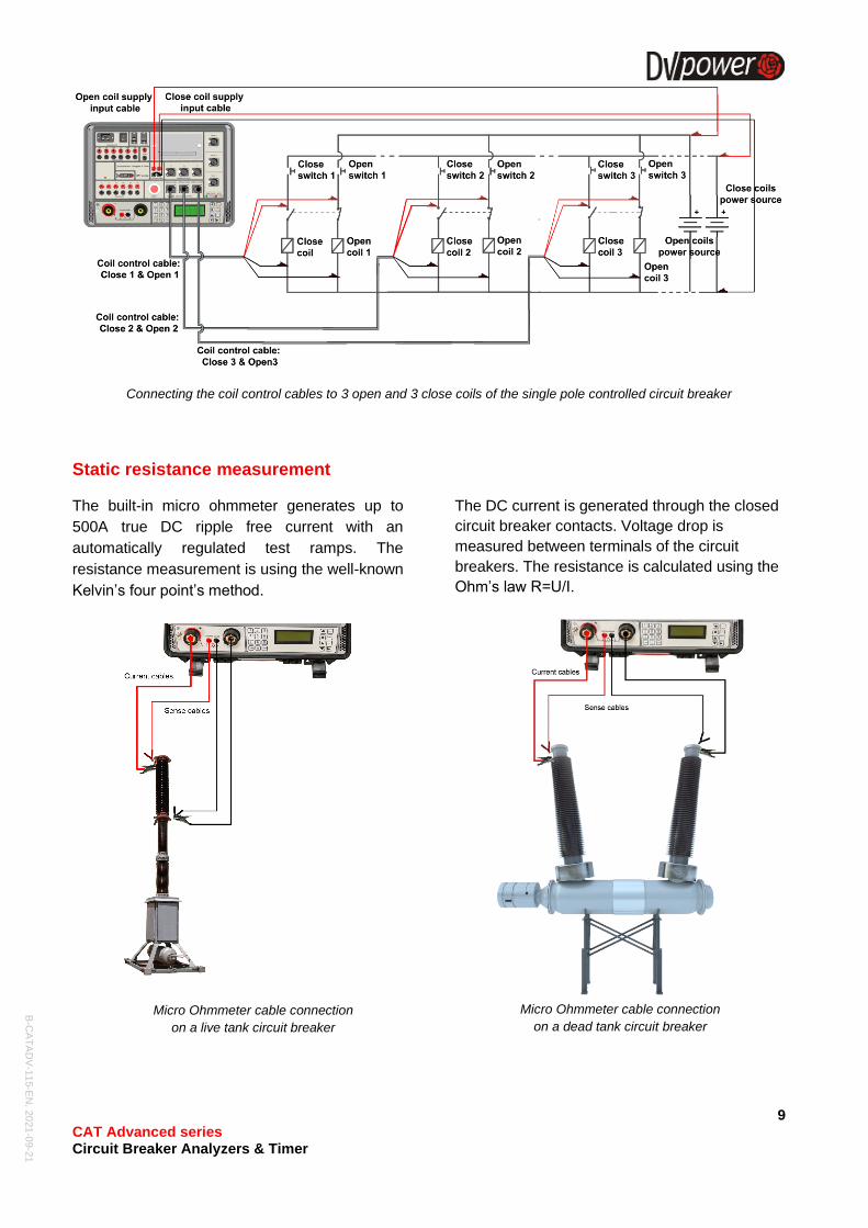
Connecting the coil control cables to 3 open and 3 close coils of the single pole controlled circuit breaker
Static resistance measurement
The built-in micro ohmmeter generates up to
500A true DC ripple free current with an
automatically regulated test ramps. The
resistance measurement is using the well-known
Kelvin’s four point’s method.
Micro Ohmmeter cable connection
on a live tank circuit breaker
The DC current is generated through the closed
circuit breaker contacts. Voltage drop is
measured between terminals of the circuit
breakers. The resistance is calculated using the
Ohm’s law R=U/I.
Micro Ohmmeter cable connection
on a dead tank circuit breaker
B-C
AT
AD
V-1
15-E
N, 2
021
-09-2
1
10 CAT Advanced series Circuit Breaker Analyzers & Timer
High – Precision module (built-in)
The high-precision module is newly developed
built-in addition to micro ohmmeter available
in CAT Advanced series. It provides an
increased precision and offers a highly
accurate contact resistance measurement in
the range from 1 μΩ to 30 μΩ, with 0,01 μΩ
resolution.
CAT Advanced series with the built-in High
Precision Module may be used for
applications on very small resistance
measurements of non-inductive test objects.
This requirement is usually met at resistance
inspections of generator circuit breakers,
welding joints, GIS testing, etc.
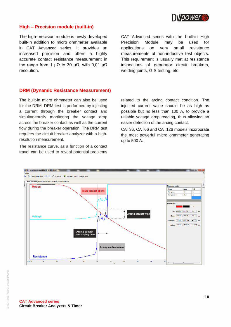
DRM (Dynamic Resistance Measurement)
The built-in micro ohmmeter can also be used
for the DRM. DRM test is performed by injecting
a current through the breaker contact and
simultaneously monitoring the voltage drop
across the breaker contact as well as the current
flow during the breaker operation. The DRM test
requires the circuit breaker analyzer with a high-
resolution measurement.
The resistance curve, as a function of a contact
travel can be used to reveal potential problems
related to the arcing contact condition. The
injected current value should be as high as
possible but no less than 100 A, to provide a
reliable voltage drop reading, thus allowing an
easier detection of the arcing contact.
CAT36, CAT66 and CAT126 models incorporate
the most powerful micro ohmmeter generating
up to 500 A.
B-C
AT
AD
V-1
15-E
N, 2
021
-09-2
1
11 CAT Advanced series Circuit Breaker Analyzers & Timer
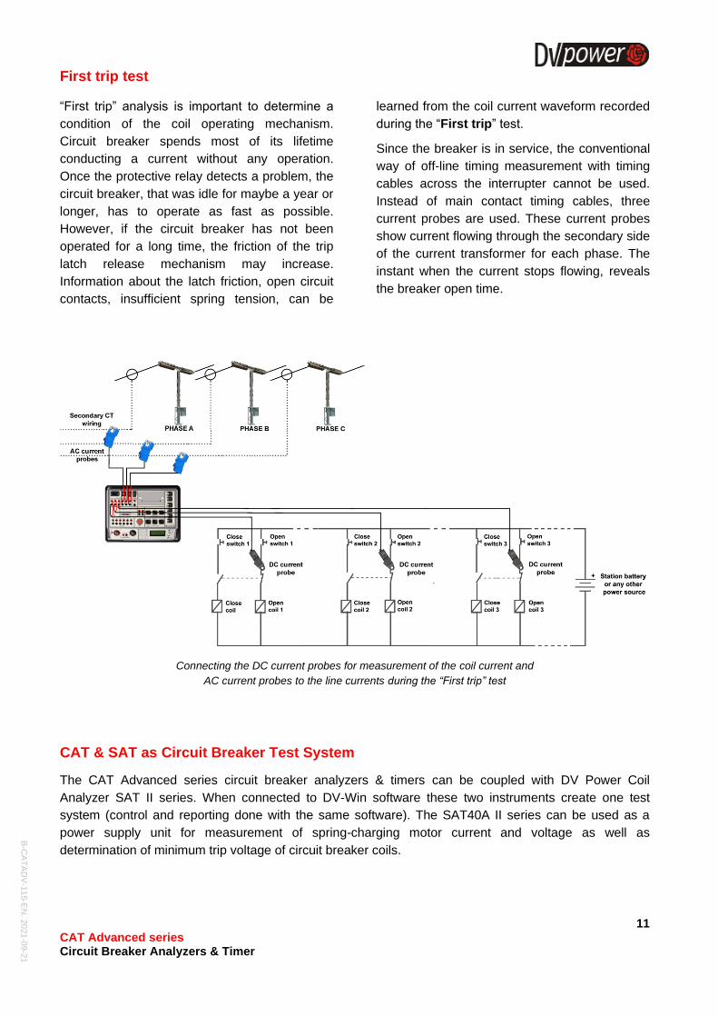
First trip test
“First trip” analysis is important to determine a
condition of the coil operating mechanism.
Circuit breaker spends most of its lifetime
conducting a current without any operation.
Once the protective relay detects a problem, the
circuit breaker, that was idle for maybe a year or
longer, has to operate as fast as possible.
However, if the circuit breaker has not been
operated for a long time, the friction of the trip
latch release mechanism may increase.
Information about the latch friction, open circuit
contacts, insufficient spring tension, can be
learned from the coil current waveform recorded
during the “First trip” test.
Since the breaker is in service, the conventional
way of off-line timing measurement with timing
cables across the interrupter cannot be used.
Instead of main contact timing cables, three
current probes are used. These current probes
show current flowing through the secondary side
of the current transformer for each phase. The
instant when the current stops flowing, reveals
the breaker open time.
Connecting the DC current probes for measurement of the coil current and
AC current probes to the line currents during the “First trip” test
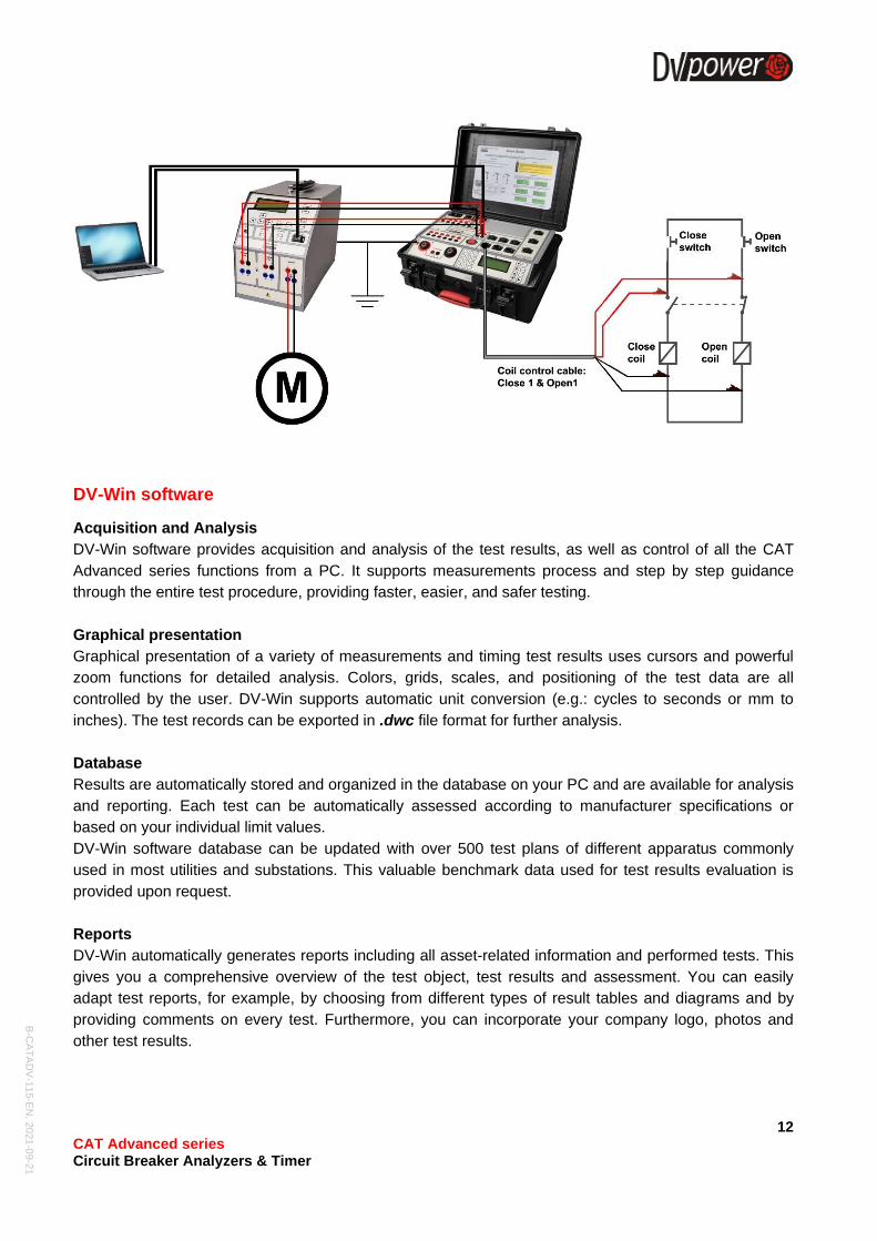
CAT & SAT as Circuit Breaker Test System
The CAT Advanced series circuit breaker analyzers & timers can be coupled with DV Power Coil
Analyzer SAT II series. When connected to DV-Win software these two instruments create one test
system (control and reporting done with the same software). The SAT40A II series can be used as a
power supply unit for measurement of spring-charging motor current and voltage as well as
determination of minimum trip voltage of circuit breaker coils.
B-C
AT
AD
V-1
15-E
N, 2
021
-09-2
1
12 CAT Advanced series Circuit Breaker Analyzers & Timer
DV-Win software
Acquisition and Analysis
DV-Win software provides acquisition and analysis of the test results, as well as control of all the CAT
Advanced series functions from a PC. It supports measurements process and step by step guidance
through the entire test procedure, providing faster, easier, and safer testing.
Graphical presentation
Graphical presentation of a variety of measurements and timing test results uses cursors and powerful
zoom functions for detailed analysis. Colors, grids, scales, and positioning of the test data are all
controlled by the user. DV-Win supports automatic unit conversion (e.g.: cycles to seconds or mm to
inches). The test records can be exported in .dwc file format for further analysis.
Database
Results are automatically stored and organized in the database on your PC and are available for analysis
and reporting. Each test can be automatically assessed according to manufacturer specifications or
based on your individual limit values.
DV-Win software database can be updated with over 500 test plans of different apparatus commonly
used in most utilities and substations. This valuable benchmark data used for test results evaluation is
provided upon request.
Reports
DV-Win automatically generates reports including all asset-related information and performed tests. This
gives you a comprehensive overview of the test object, test results and assessment. You can easily
adapt test reports, for example, by choosing from different types of result tables and diagrams and by
providing comments on every test. Furthermore, you can incorporate your company logo, photos and
other test results.
B-C
AT
AD
V-1
15-E
N, 2
021
-09-2
1
13 CAT Advanced series Circuit Breaker Analyzers & Timer
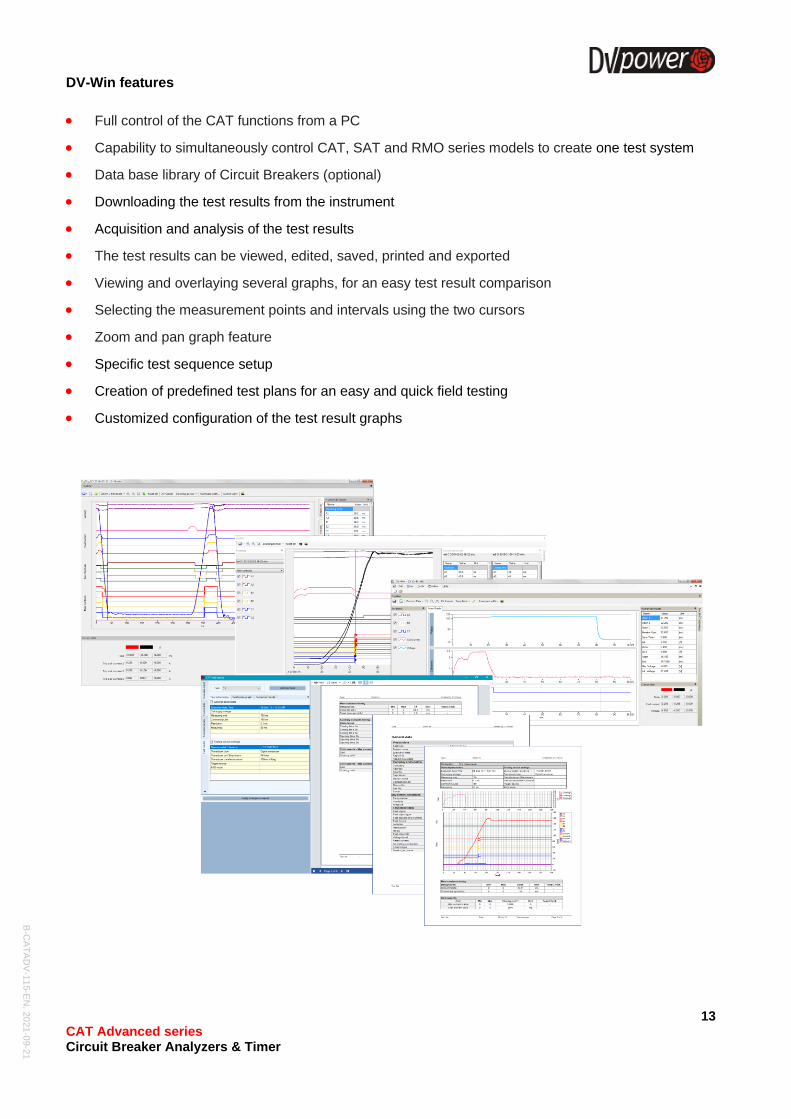
DV-Win features
• Full control of the CAT functions from a PC
• Capability to simultaneously control CAT, SAT and RMO series models to create one test system
• Data base library of Circuit Breakers (optional)
• Downloading the test results from the instrument
• Acquisition and analysis of the test results
• The test results can be viewed, edited, saved, printed and exported
• Viewing and overlaying several graphs, for an easy test result comparison
• Selecting the measurement points and intervals using the two cursors
• Zoom and pan graph feature
• Specific test sequence setup
• Creation of predefined test plans for an easy and quick field testing
• Customized configuration of the test result graphs
B-C
AT
AD
V-1
15-E
N, 2
021
-09-2
1
14 CAT Advanced series Circuit Breaker Analyzers & Timer
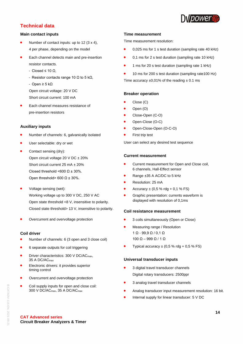
Technical data
Main contact inputs
• Number of contact inputs: up to 12 (3 x 4),
4 per phase, depending on the model
• Each channel detects main and pre-insertion
resistor contacts.
- Closed ≤ 10 Ω,
- Resistor contacts range 10 Ω to 5 kΩ,
- Open ≥ 5 kΩ
Open circuit voltage: 20 V DC
Short circuit current: 100 mA
• Each channel measures resistance of
pre-insertion resistors
Auxiliary inputs
• Number of channels: 6, galvanically isolated
• User selectable: dry or wet
• Contact sensing (dry):
Open circuit voltage 20 V DC ± 20%
Short circuit current 25 mA ± 20%
Closed threshold <600 Ω ± 30%.
Open threshold> 600 Ω ± 30%.
• Voltage sensing (wet):
Working voltage up to 300 V DC, 250 V AC
Open state threshold <8 V, insensitive to polarity.
Closed state threshold> 13 V, insensitive to polarity.
• Overcurrent and overvoltage protection
Coil driver
• Number of channels: 6 (3 open and 3 close coil)
• 6 separate outputs for coil triggering
• Driver characteristics: 300 V DC/ACmax, 35 A DC/ACmax
• Electronic drivers: it provides superior timing control
• Overcurrent and overvoltage protection
• Coil supply inputs for open and close coil: 300 V DC/ACmax, 35 A DC/ACmax
Time measurement
Time measurement resolution:
• 0,025 ms for 1 s test duration (sampling rate 40 kHz)
• 0,1 ms for 2 s test duration (sampling rate 10 kHz)
• 1 ms for 20 s test duration (sampling rate 1 kHz)
• 10 ms for 200 s test duration (sampling rate100 Hz)
Time accuracy ±0,01% of the reading ± 0.1 ms
Breaker operation
• Close (C)
• Open (O)
• Close-Open (C-O)
• Open-Close (O-C)
• Open-Close-Open (O-C-O)
• First trip test
User can select any desired test sequence
Current measurement
• Current measurement for Open and Close coil,
6 channels, Hall-Effect sensor
• Range ±35 A AC/DC to 5 kHz
• Resolution: 25 mA
• Accuracy ± (0,5 % rdg + 0,1 % FS)
• Graphic presentation: currents waveform is
displayed with resolution of 0,1ms
Coil resistance measurement
• 3 coils simultaneously (Open or Close)
• Measuring range / Resolution
1 Ω - 99,9 Ω / 0,1 Ω
100 Ω – 999 Ω / 1 Ω
• Typical accuracy ± (0,5 % rdg + 0,5 % FS)
Universal transducer inputs
• 3 digital travel transducer channels
Digital rotary transducers: 2500ppr
• 3 analog travel transducer channels
• Analog transducer input measurement resolution: 16 bit.
• Internal supply for linear transducer: 5 V DC
B-C
AT
AD
V-1
15-E
N, 2
021
-09-2
1
15 CAT Advanced series Circuit Breaker Analyzers & Timer
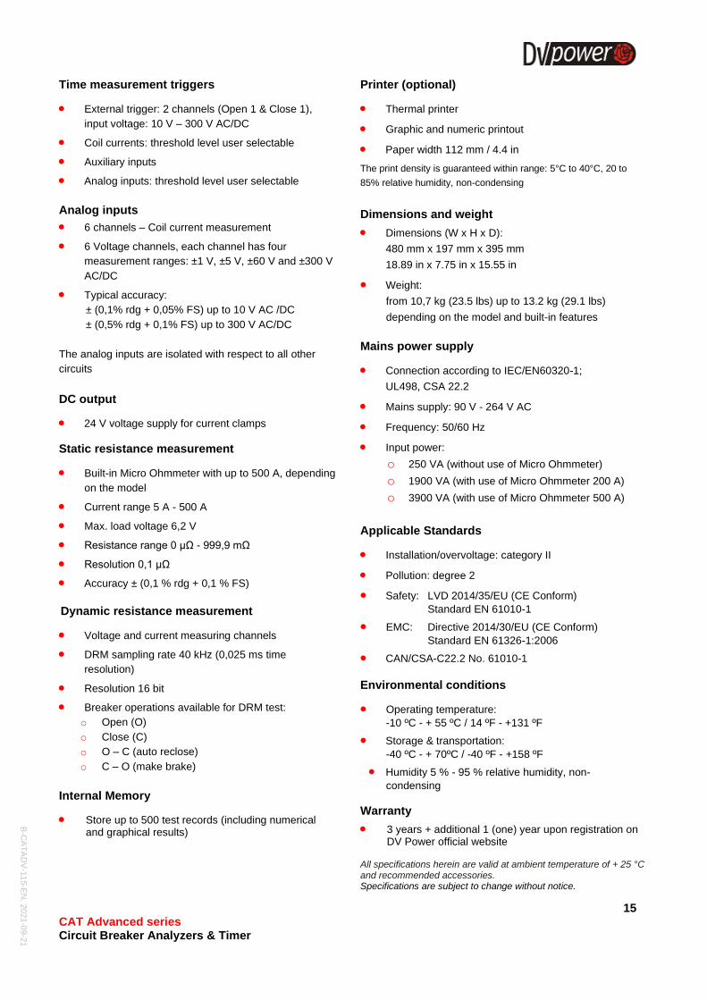
Time measurement triggers
• External trigger: 2 channels (Open 1 & Close 1),
input voltage: 10 V – 300 V AC/DC
• Coil currents: threshold level user selectable
• Auxiliary inputs
• Analog inputs: threshold level user selectable
Analog inputs
• 6 channels – Coil current measurement
• 6 Voltage channels, each channel has four
measurement ranges: ±1 V, ±5 V, ±60 V and ±300 V
AC/DC
• Typical accuracy:
± (0,1% rdg + 0,05% FS) up to 10 V AC /DC
± (0,5% rdg + 0,1% FS) up to 300 V AC/DC
The analog inputs are isolated with respect to all other
circuits
DC output
• 24 V voltage supply for current clamps
Static resistance measurement
• Built-in Micro Ohmmeter with up to 500 A, depending
on the model
• Current range 5 A - 500 A
• Max. load voltage 6,2 V
• Resistance range 0 µΩ - 999,9 mΩ
• Resolution 0,1 µΩ
• Accuracy ± (0,1 % rdg + 0,1 % FS)
Dynamic resistance measurement
• Voltage and current measuring channels
• DRM sampling rate 40 kHz (0,025 ms time
resolution)
• Resolution 16 bit
• Breaker operations available for DRM test:
o Open (O)
o Close (C)
o O – C (auto reclose)
o C – O (make brake)
Internal Memory
• Store up to 500 test records (including numerical and graphical results)
Printer (optional)
• Thermal printer
• Graphic and numeric printout
• Paper width 112 mm / 4.4 in
The print density is guaranteed within range: 5°C to 40°C, 20 to
85% relative humidity, non-condensing
Dimensions and weight
• Dimensions (W x H x D):
480 mm x 197 mm x 395 mm
18.89 in x 7.75 in x 15.55 in
• Weight:
from 10,7 kg (23.5 lbs) up to 13.2 kg (29.1 lbs)
depending on the model and built-in features
Mains power supply
• Connection according to IEC/EN60320-1;
UL498, CSA 22.2
• Mains supply: 90 V - 264 V AC
• Frequency: 50/60 Hz
• Input power:
o 250 VA (without use of Micro Ohmmeter)
o 1900 VA (with use of Micro Ohmmeter 200 A)
o 3900 VA (with use of Micro Ohmmeter 500 A)
Applicable Standards
• Installation/overvoltage: category II
• Pollution: degree 2
• Safety: LVD 2014/35/EU (CE Conform)
Standard EN 61010-1
• EMC: Directive 2014/30/EU (CE Conform)
Standard EN 61326-1:2006
• CAN/CSA-C22.2 No. 61010-1
Environmental conditions
• Operating temperature:
-10 ºC - + 55 ºC / 14 ºF - +131 ºF
• Storage & transportation:
-40 ºC - + 70ºC / -40 ºF - +158 ºF
• Humidity 5 % - 95 % relative humidity, non-
condensing
Warranty
• 3 years + additional 1 (one) year upon registration on DV Power official website
All specifications herein are valid at ambient temperature of + 25 °C and recommended accessories. Specifications are subject to change without notice.

B-C
AT
AD
V-1
15-E
N, 2
021
-09-2
1
16 CAT Advanced series Circuit Breaker Analyzers & Timer
Accessories
Main contact cables 5 m (16.4 ft) with SCT clamps (four breaks per
phase) (CM-05-12MXST)
Main contact cables 5 m (16.4 ft) with SCT clamps (two breaks per phase)
(CM-05-65MXST)
Main contact cables 5 m (16.4 ft) with SCT clamps (one break per phase)
(CM-05-34MXST)
Main contacts extensions cables 10 m (32.8 ft)*
(E6-10-12MXFX)
Main contacts extensions cables 10 m (32.8 ft)*
(E3-10-65MXFX)
Coil control cable set 5 m (16.4 ft) with banana
plugs (Single-pole control - 6
coil channels) (CO-05-6BC5B1)
Coil control cable 5 m (16.4 ft) with banana plugs (Three-pole control - 2 coil
channels) (CO-05-00C5B1)
Coil supply cable set 4 x 5 m 2,5 mm2 (16.4 ft)
with banana plugs (CS-05-02BPBP)
Sense cables 2 x 10 (32.8 ft) m with alligator clamps
A2 (S2-10-02BPA2)
Current cables 2 x 10 m 50 mm2 (32.8 ft, 0 AWG) with
battery clamps (C2-10-50VMB3)
Current cables 2 x 10 m 25 mm2 (32.8 ft, 3 AWG) with
battery clamps (C2-10-25LMB1)
Auxiliary contacts cable set 12 x 5 m (16.4 ft) with
banana plugs* (AX-05-02BPBP)
Analog channels cable set 12 x 5 m (16.4 ft) with
banana plugs* (AN-05-02BPBP)
Current cables with branch connectors 2 x (3 x 5 m, 16 mm2) with SCT
clamps (C6BC-05-16GMST)
Cable bag (CABLE-BAG-00)
B-C
AT
AD
V-1
15-E
N, 2
021
-09-2
1
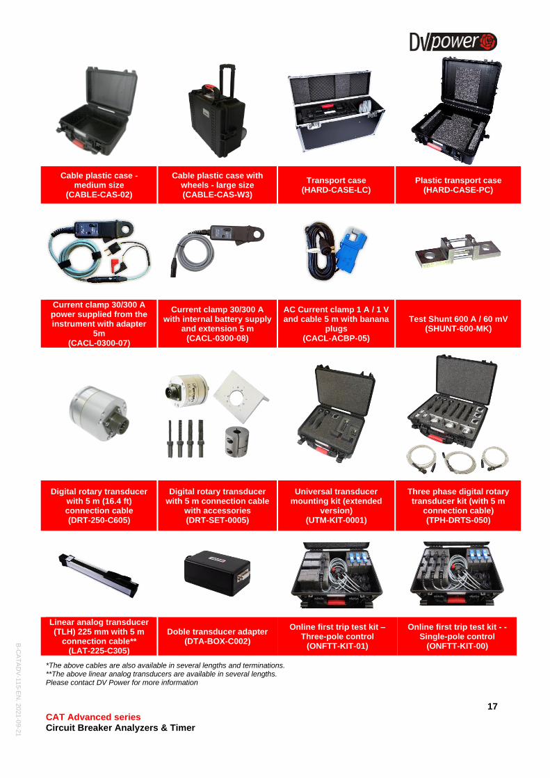
17 CAT Advanced series Circuit Breaker Analyzers & Timer
Cable plastic case - medium size
(CABLE-CAS-02)
Cable plastic case with wheels - large size (CABLE-CAS-W3)
Transport case (HARD-CASE-LC)
Plastic transport case (HARD-CASE-PC)
Current clamp 30/300 A power supplied from the instrument with adapter
5m (CACL-0300-07)
Current clamp 30/300 A with internal battery supply
and extension 5 m (CACL-0300-08)
AC Current clamp 1 A / 1 V and cable 5 m with banana
plugs (CACL-ACBP-05)
Test Shunt 600 A / 60 mV (SHUNT-600-MK)
Digital rotary transducer with 5 m (16.4 ft) connection cable (DRT-250-C605)
Digital rotary transducer with 5 m connection cable
with accessories (DRT-SET-0005)
Universal transducer mounting kit (extended
version) (UTM-KIT-0001)
Three phase digital rotary transducer kit (with 5 m
connection cable) (TPH-DRTS-050)
Linear analog transducer (TLH) 225 mm with 5 m
connection cable** (LAT-225-C305)
Doble transducer adapter (DTA-BOX-C002)
Online first trip test kit – Three-pole control
(ONFTT-KIT-01)
Online first trip test kit - - Single-pole control
(ONFTT-KIT-00)
*The above cables are also available in several lengths and terminations. **The above linear analog transducers are available in several lengths. Please contact DV Power for more information
B-C
AT
AD
V-1
15-E
N, 2
021
-09-2
1
18 CAT Advanced series Circuit Breaker Analyzers & Timer
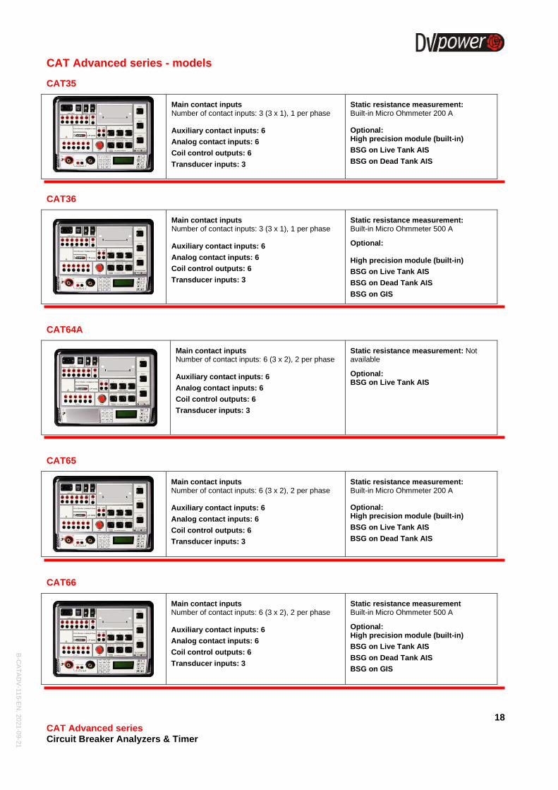
CAT Advanced series - models
CAT35
Main contact inputs Number of contact inputs: 3 (3 x 1), 1 per phase Auxiliary contact inputs: 6
Analog contact inputs: 6
Coil control outputs: 6
Transducer inputs: 3
Static resistance measurement: Built-in Micro Ohmmeter 200 A
Optional: High precision module (built-in)
BSG on Live Tank AIS
BSG on Dead Tank AIS
CAT36
Main contact inputs Number of contact inputs: 3 (3 x 1), 1 per phase Auxiliary contact inputs: 6
Analog contact inputs: 6
Coil control outputs: 6
Transducer inputs: 3
Static resistance measurement: Built-in Micro Ohmmeter 500 A
Optional: High precision module (built-in)
BSG on Live Tank AIS
BSG on Dead Tank AIS
BSG on GIS
CAT64A
Main contact inputs Number of contact inputs: 6 (3 x 2), 2 per phase Auxiliary contact inputs: 6
Analog contact inputs: 6
Coil control outputs: 6
Transducer inputs: 3
Static resistance measurement: Not available
Optional: BSG on Live Tank AIS
CAT65
Main contact inputs Number of contact inputs: 6 (3 x 2), 2 per phase Auxiliary contact inputs: 6
Analog contact inputs: 6
Coil control outputs: 6
Transducer inputs: 3
Static resistance measurement: Built-in Micro Ohmmeter 200 A
Optional: High precision module (built-in)
BSG on Live Tank AIS
BSG on Dead Tank AIS
CAT66
Main contact inputs Number of contact inputs: 6 (3 x 2), 2 per phase Auxiliary contact inputs: 6
Analog contact inputs: 6
Coil control outputs: 6
Transducer inputs: 3
Static resistance measurement Built-in Micro Ohmmeter 500 A
Optional: High precision module (built-in)
BSG on Live Tank AIS
BSG on Dead Tank AIS
BSG on GIS
B-C
AT
AD
V-1
15-E
N, 2
021
-09-2
1
19 CAT Advanced series Circuit Breaker Analyzers & Timer
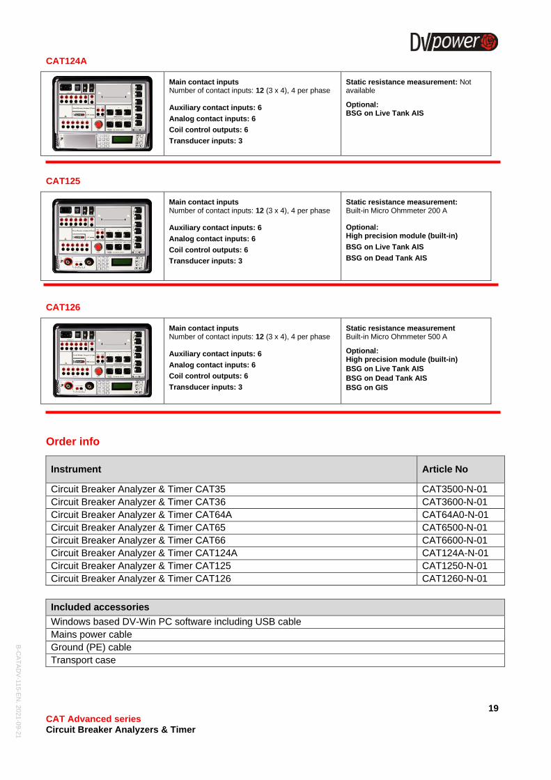
CAT124A
Main contact inputs Number of contact inputs: 12 (3 x 4), 4 per phase Auxiliary contact inputs: 6
Analog contact inputs: 6
Coil control outputs: 6
Transducer inputs: 3
Static resistance measurement: Not available
Optional: BSG on Live Tank AIS
CAT125
Main contact inputs Number of contact inputs: 12 (3 x 4), 4 per phase Auxiliary contact inputs: 6
Analog contact inputs: 6
Coil control outputs: 6
Transducer inputs: 3
Static resistance measurement: Built-in Micro Ohmmeter 200 A
Optional: High precision module (built-in)
BSG on Live Tank AIS
BSG on Dead Tank AIS
CAT126
Main contact inputs Number of contact inputs: 12 (3 x 4), 4 per phase Auxiliary contact inputs: 6
Analog contact inputs: 6
Coil control outputs: 6
Transducer inputs: 3
Static resistance measurement Built-in Micro Ohmmeter 500 A
Optional: High precision module (built-in)
BSG on Live Tank AIS
BSG on Dead Tank AIS
BSG on GIS
Order info
Instrument Article No
Circuit Breaker Analyzer & Timer CAT35 CAT3500-N-01
Circuit Breaker Analyzer & Timer CAT36 CAT3600-N-01
Circuit Breaker Analyzer & Timer CAT64A CAT64A0-N-01
Circuit Breaker Analyzer & Timer CAT65 CAT6500-N-01
Circuit Breaker Analyzer & Timer CAT66 CAT6600-N-01
Circuit Breaker Analyzer & Timer CAT124A CAT124A-N-01
Circuit Breaker Analyzer & Timer CAT125 CAT1250-N-01
Circuit Breaker Analyzer & Timer CAT126 CAT1260-N-01
Included accessories
Windows based DV-Win PC software including USB cable
Mains power cable
Ground (PE) cable
Transport case
B-C
AT
AD
V-1
15-E
N, 2
021
-09-2
1
20 CAT Advanced series Circuit Breaker Analyzers & Timer
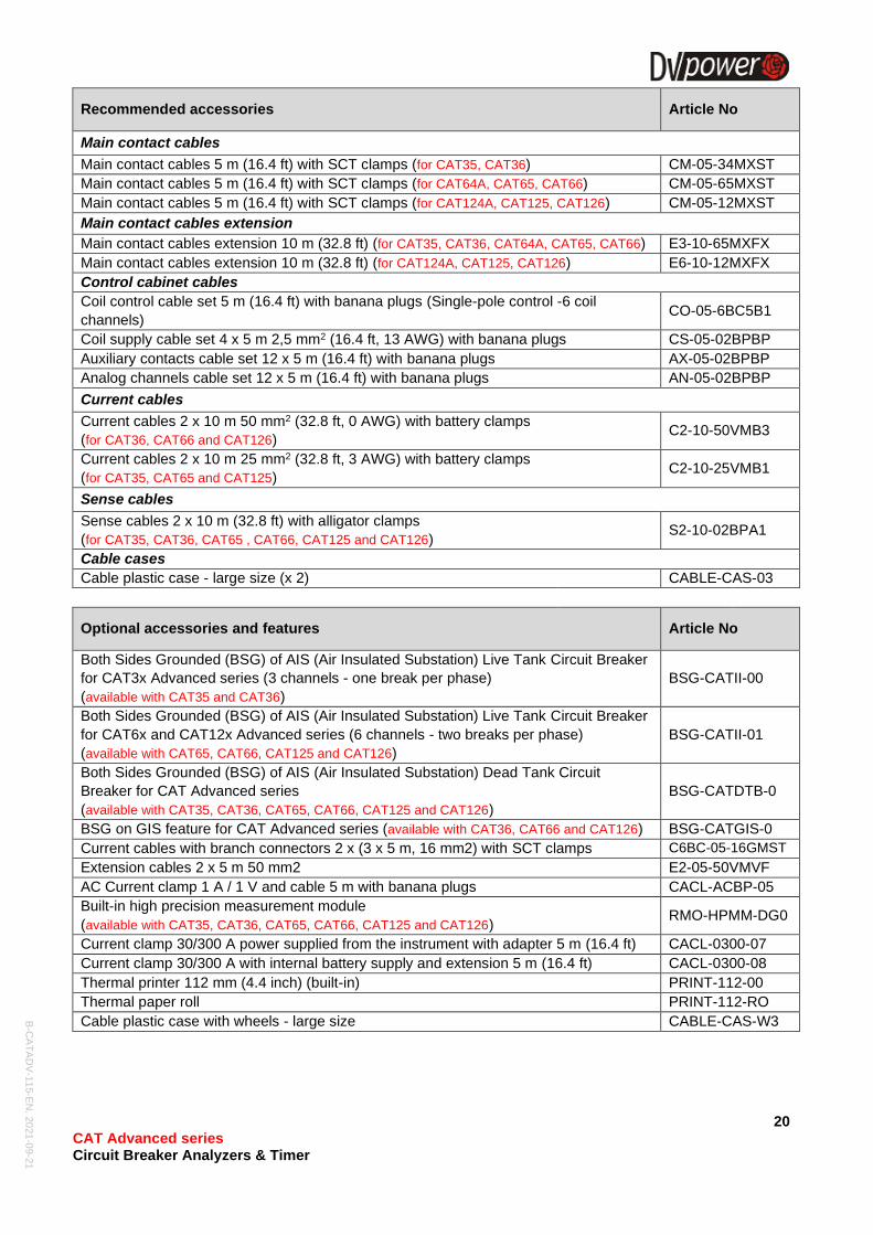
Recommended accessories Article No
Main contact cables
Main contact cables 5 m (16.4 ft) with SCT clamps (for CAT35, CAT36) CM-05-34MXST
Main contact cables 5 m (16.4 ft) with SCT clamps (for CAT64A, CAT65, CAT66) CM-05-65MXST
Main contact cables 5 m (16.4 ft) with SCT clamps (for CAT124A, CAT125, CAT126) CM-05-12MXST
Main contact cables extension
Main contact cables extension 10 m (32.8 ft) (for CAT35, CAT36, CAT64A, CAT65, CAT66) E3-10-65MXFX
Main contact cables extension 10 m (32.8 ft) (for CAT124A, CAT125, CAT126) E6-10-12MXFX
Control cabinet cables
Coil control cable set 5 m (16.4 ft) with banana plugs (Single-pole control -6 coil
channels) CO-05-6BC5B1
Coil supply cable set 4 x 5 m 2,5 mm2 (16.4 ft, 13 AWG) with banana plugs CS-05-02BPBP
Auxiliary contacts cable set 12 x 5 m (16.4 ft) with banana plugs AX-05-02BPBP
Analog channels cable set 12 x 5 m (16.4 ft) with banana plugs AN-05-02BPBP
Current cables
Current cables 2 x 10 m 50 mm2 (32.8 ft, 0 AWG) with battery clamps
(for CAT36, CAT66 and CAT126) C2-10-50VMB3
Current cables 2 x 10 m 25 mm2 (32.8 ft, 3 AWG) with battery clamps
(for CAT35, CAT65 and CAT125) C2-10-25VMB1
Sense cables
Sense cables 2 x 10 m (32.8 ft) with alligator clamps
(for CAT35, CAT36, CAT65 , CAT66, CAT125 and CAT126) S2-10-02BPA1
Cable cases
Cable plastic case - large size (x 2) CABLE-CAS-03
Optional accessories and features Article No
Both Sides Grounded (BSG) of AIS (Air Insulated Substation) Live Tank Circuit Breaker
for CAT3x Advanced series (3 channels - one break per phase)
(available with CAT35 and CAT36)
BSG-CATII-00
Both Sides Grounded (BSG) of AIS (Air Insulated Substation) Live Tank Circuit Breaker
for CAT6x and CAT12x Advanced series (6 channels - two breaks per phase)
(available with CAT65, CAT66, CAT125 and CAT126)
BSG-CATII-01
Both Sides Grounded (BSG) of AIS (Air Insulated Substation) Dead Tank Circuit
Breaker for CAT Advanced series
(available with CAT35, CAT36, CAT65, CAT66, CAT125 and CAT126)
BSG-CATDTB-0
BSG on GIS feature for CAT Advanced series (available with CAT36, CAT66 and CAT126) BSG-CATGIS-0
Current cables with branch connectors 2 x (3 x 5 m, 16 mm2) with SCT clamps C6BC-05-16GMST
Extension cables 2 x 5 m 50 mm2 E2-05-50VMVF
AC Current clamp 1 A / 1 V and cable 5 m with banana plugs CACL-ACBP-05
Built-in high precision measurement module
(available with CAT35, CAT36, CAT65, CAT66, CAT125 and CAT126) RMO-HPMM-DG0
Current clamp 30/300 A power supplied from the instrument with adapter 5 m (16.4 ft) CACL-0300-07
Current clamp 30/300 A with internal battery supply and extension 5 m (16.4 ft) CACL-0300-08
Thermal printer 112 mm (4.4 inch) (built-in) PRINT-112-00
Thermal paper roll PRINT-112-RO
Cable plastic case with wheels - large size CABLE-CAS-W3
B-C
AT
AD
V-1
15-E
N, 2
021
-09-2
1
21 CAT Advanced series Circuit Breaker Analyzers & Timer
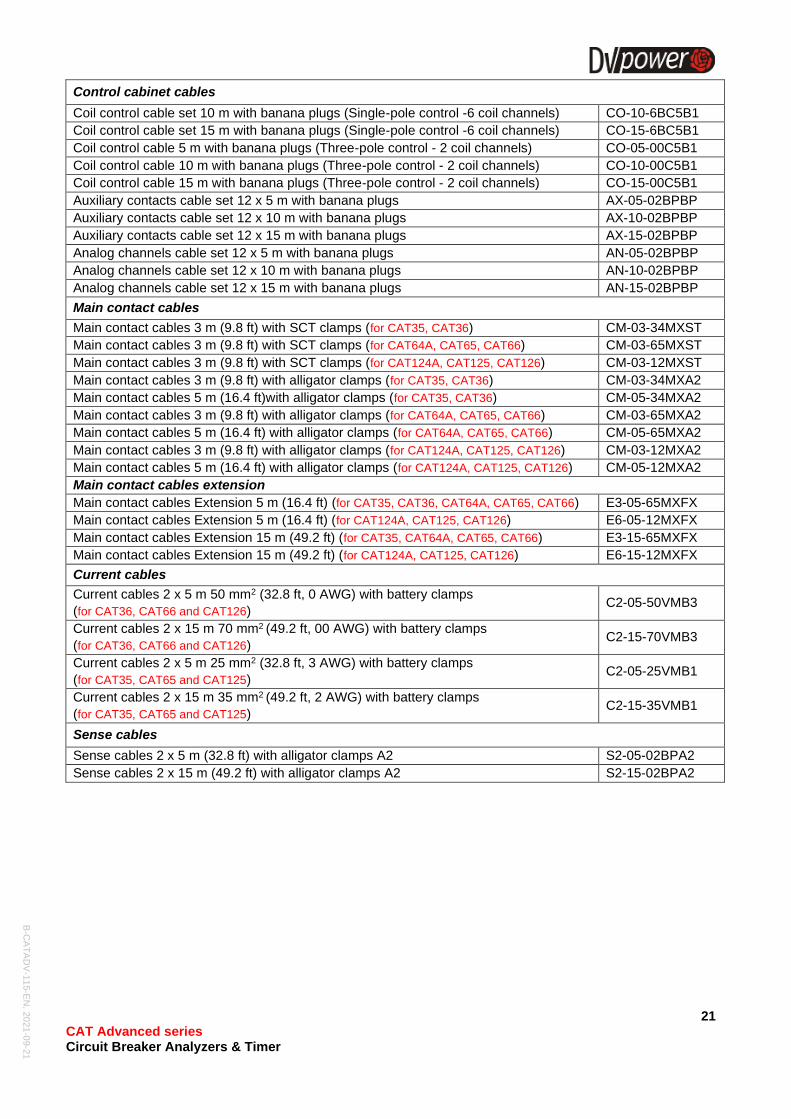
Control cabinet cables
Coil control cable set 10 m with banana plugs (Single-pole control -6 coil channels) CO-10-6BC5B1
Coil control cable set 15 m with banana plugs (Single-pole control -6 coil channels) CO-15-6BC5B1
Coil control cable 5 m with banana plugs (Three-pole control - 2 coil channels) CO-05-00C5B1
Coil control cable 10 m with banana plugs (Three-pole control - 2 coil channels) CO-10-00C5B1
Coil control cable 15 m with banana plugs (Three-pole control - 2 coil channels) CO-15-00C5B1
Auxiliary contacts cable set 12 x 5 m with banana plugs AX-05-02BPBP
Auxiliary contacts cable set 12 x 10 m with banana plugs AX-10-02BPBP
Auxiliary contacts cable set 12 x 15 m with banana plugs AX-15-02BPBP
Analog channels cable set 12 x 5 m with banana plugs AN-05-02BPBP
Analog channels cable set 12 x 10 m with banana plugs AN-10-02BPBP
Analog channels cable set 12 x 15 m with banana plugs AN-15-02BPBP
Main contact cables
Main contact cables 3 m (9.8 ft) with SCT clamps (for CAT35, CAT36) CM-03-34MXST
Main contact cables 3 m (9.8 ft) with SCT clamps (for CAT64A, CAT65, CAT66) CM-03-65MXST
Main contact cables 3 m (9.8 ft) with SCT clamps (for CAT124A, CAT125, CAT126) CM-03-12MXST
Main contact cables 3 m (9.8 ft) with alligator clamps (for CAT35, CAT36) CM-03-34MXA2
Main contact cables 5 m (16.4 ft)with alligator clamps (for CAT35, CAT36) CM-05-34MXA2
Main contact cables 3 m (9.8 ft) with alligator clamps (for CAT64A, CAT65, CAT66) CM-03-65MXA2
Main contact cables 5 m (16.4 ft) with alligator clamps (for CAT64A, CAT65, CAT66) CM-05-65MXA2
Main contact cables 3 m (9.8 ft) with alligator clamps (for CAT124A, CAT125, CAT126) CM-03-12MXA2
Main contact cables 5 m (16.4 ft) with alligator clamps (for CAT124A, CAT125, CAT126) CM-05-12MXA2
Main contact cables extension
Main contact cables Extension 5 m (16.4 ft) (for CAT35, CAT36, CAT64A, CAT65, CAT66) E3-05-65MXFX
Main contact cables Extension 5 m (16.4 ft) (for CAT124A, CAT125, CAT126) E6-05-12MXFX
Main contact cables Extension 15 m (49.2 ft) (for CAT35, CAT64A, CAT65, CAT66) E3-15-65MXFX
Main contact cables Extension 15 m (49.2 ft) (for CAT124A, CAT125, CAT126) E6-15-12MXFX
Current cables
Current cables 2 x 5 m 50 mm2 (32.8 ft, 0 AWG) with battery clamps
(for CAT36, CAT66 and CAT126) C2-05-50VMB3
Current cables 2 x 15 m 70 mm2 (49.2 ft, 00 AWG) with battery clamps
(for CAT36, CAT66 and CAT126) C2-15-70VMB3
Current cables 2 x 5 m 25 mm2 (32.8 ft, 3 AWG) with battery clamps
(for CAT35, CAT65 and CAT125) C2-05-25VMB1
Current cables 2 x 15 m 35 mm2 (49.2 ft, 2 AWG) with battery clamps
(for CAT35, CAT65 and CAT125) C2-15-35VMB1
Sense cables
Sense cables 2 x 5 m (32.8 ft) with alligator clamps A2 S2-05-02BPA2
Sense cables 2 x 15 m (49.2 ft) with alligator clamps A2 S2-15-02BPA2
B-C
AT
AD
V-1
15-E
N, 2
021
-09-2
1
22 IBEKO Power AB Contact
Stockholmsvägen 18 Phone: +46 70 0925 000
181 50 Lidingö, Sweden E-mail: [email protected]
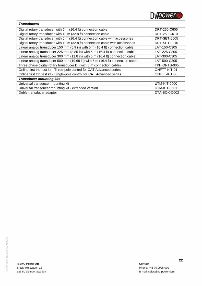
Transducers
Digital rotary transducer with 5 m (16.4 ft) connection cable DRT-250-C605
Digital rotary transducer with 10 m (32.8 ft) connection cable DRT-250-C610
Digital rotary transducer with 5 m (16.4 ft) connection cable with accessories DRT-SET-0005
Digital rotary transducer with 10 m (32.8 ft) connection cable with accessories DRT-SET-0010
Linear analog transducer 150 mm (5.9 in) with 5 m (16.4 ft) connection cable LAT-150-C305
Linear analog transducer 225 mm (8.85 in) with 5 m (16.4 ft) connection cable LAT-225-C305
Linear analog transducer 300 mm (11.8 in) with 5 m (16.4 ft) connection cable LAT-300-C305
Linear analog transducer 500 mm (19.68 in) with 5 m (16.4 ft) connection cable LAT-500-C305
Three phase digital rotary transducer kit (with 5 m connection cable) TPH-DRTS-005
Online first trip test kit - Three-pole control for CAT Advanced series ONFTT-KIT-01
Online first trip test kit - Single-pole control for CAT Advanced series ONFTT-KIT-00
Transducer mounting kits
Universal transducer mounting kit UTM-KIT-0000
Universal transducer mounting kit - extended version UTM-KIT-0001
Doble transducer adapter DTA-BOX-C002