Embed Size (px)
Citation preview
PD-5WS-DV, PD-6ANS
® Specif icat ion Submittal page
Job Name:
Job Number:
Model Numbers:
Caséta® Wireless In-Wall Switch
369831c 1 10.28/15
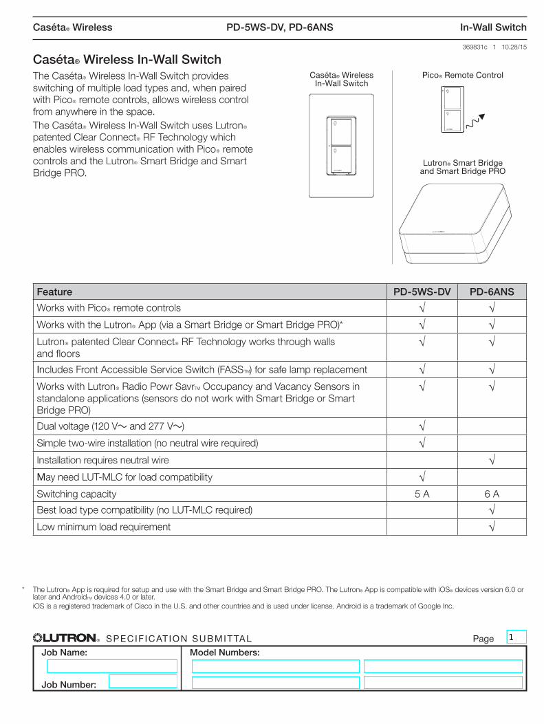
Caséta® Wireless In-Wall Switch The CasétaR Wireless In-Wall Switch provides
switching of multiple load types and, when paired with PicoR remote controls, allows wireless control from anywhere in the space.The CasétaR Wireless In-Wall Switch uses LutronR patented Clear ConnectR RF Technology which enables wireless communication with PicoR remote controls and the LutronR Smart Bridge and Smart Bridge PRO.
Caséta® Wireless In-Wall Switch
Pico® Remote Control
Lutron® Smart Bridge and Smart Bridge PRO
* The Lutron® App is required for setup and use with the Smart Bridge and Smart Bridge PRO. The Lutron® App is compatible with iOS® devices version 6.0 or later and AndroidTM devices 4.0 or later.
iOS is a registered trademark of Cisco in the U.S. and other countries and is used under license. Android is a trademark of Google Inc.
Feature PD-5WS-DV PD-6ANS
Works with PicoR remote controls √ √Works with the LutronR App (via a Smart Bridge or Smart Bridge PRO)* √ √LutronR patented Clear ConnectR RF Technology works through walls and floors
√ √
Includes Front Accessible Service Switch (FASST) for safe lamp replacement √ √Works with LutronR Radio Powr SavrT Occupancy and Vacancy Sensors in standalone applications (sensors do not work with Smart Bridge or Smart Bridge PRO)
√ √
Dual voltage (120 V~ and 277 V~) √Simple two-wire installation (no neutral wire required) √Installation requires neutral wire √May need LUT-MLC for load compatibility √Switching capacity 5 A 6 A
Best load type compatibility (no LUT-MLC required) √Low minimum load requirement √

PD-5WS-DV, PD-6ANS
® Specif icat ion Submittal page
Job Name:
Job Number:
Model Numbers:
Caséta® Wireless In-Wall Switch
369831c 2 10.28/15
Load Type and Capacity
Model Number Description Voltage Load Type Minimum LoadMaximum Load 4
Not Ganged End of Gang Middle of Gang
PD-5WS-DV-XX1, 2 Two-wire switch
120 V~ Incandescent / Halogen 25 W 600 W 450 W 350 W
277 V~ Incandescent / Halogen 25 W 1350 W 1100 W 800 W
120 V~ MLV 25 W 600 VA /475 W 450 VA / 350 W 350 VA / 275 W277 V~ MLV 25 W 1350 VA /1075 W 1100 VA / 875 W 800 VA / 625 W
120 V~ General Purpose Fan 0.4 A 3 A 3 A 3 A
120 / 277 V~ LED Use LUT-MLC3 5 A 4 A 3 A120 / 277 V~ Fluorescent Use LUT-MLC3 5 A 4 A 3 A120 V~ ELV Use LUT-MLC3 600 W 450 W 350 W277 V~ ELV Use LUT-MLC3 1350 W 1100 W 800 W
PD-6ANS-XX2, 5 Neutral-wire switch 120 V~
Incandescent / Halogen 10 W 720 W 720 W 600 W
MLV 10 W 720 VA 720 VA 600 VA
Fan 0.1 A 3.6 A 3.6 A 3.6 A
LED 1 bulb 6 A 6 A 5 AFluorescent 1 ballast 6 A 6 A 5 AELV 10 W 720 VA 720 VA 600 VA
1 No Neutral Required.2 “XX” in the model number represents color/finish code.3 To ensure proper operation of the switch with LED, fluorescent, and ELV loads, a LUT-MLC may be required, especially at lower wattages. If the status LED
on the switch is flashing or solid red in color, a LUT-MLC must be installed. To guarantee best performance, installing a LUT-MLC with these load types regardless of wattage is recommended. Rarely, some load types may still flicker or glow in the off state even with the LUT-MLC installed, in which case a different load may be required.
4 See “Ganging and Derating” section.5 Neutral required.
PD-5WS-DV, PD-6ANS
® Specif icat ion Submittal page
Job Name:
Job Number:
Model Numbers:
Caséta® Wireless In-Wall Switch
369831c 3 10.28/15
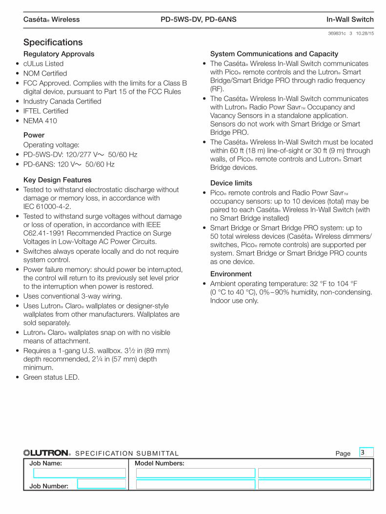
SpecificationsRegulatory Approvals
• cULus Listed• NOM Certified• FCC Approved. Complies with the limits for a Class B
digital device, pursuant to Part 15 of the FCC Rules• Industry Canada Certified• IFTEL Certified• NEMA 410
PowerOperating voltage:
• PD-5WS-DV: 120 / 277 V~ 50 / 60 Hz• PD-6ANS: 120 V~ 50 / 60 Hz
Key Design Features• Tested to withstand electrostatic discharge without
damage or memory loss, in accordance with IEC 61000-4-2.
• Tested to withstand surge voltages without damage or loss of operation, in accordance with IEEE C62.41-1991 Recommended Practice on Surge Voltages in Low-Voltage AC Power Circuits.
• Switches always operate locally and do not require system control.
• Power failure memory: should power be interrupted, the control will return to its previously set level prior to the interruption when power is restored.
• Uses conventional 3-way wiring.• Uses LutronR ClaroR wallplates or designer-style
wallplates from other manufacturers. Wallplates are sold separately.
• LutronR ClaroR wallplates snap on with no visible means of attachment.
• Requires a 1-gang U.S. wallbox. 31⁄2 in (89 mm) depth recommended, 21⁄4 in (57 mm) depth minimum.
• Green status LED.
System Communications and Capacity• The CasétaR Wireless In-Wall Switch communicates
with PicoR remote controls and the LutronR Smart Bridge/Smart Bridge PRO through radio frequency (RF).
• The CasétaR Wireless In-Wall Switch communicates with LutronR Radio Powr SavrT Occupancy and Vacancy Sensors in a standalone application. Sensors do not work with Smart Bridge or Smart Bridge PRO.
• The CasétaR Wireless In-Wall Switch must be located within 60 ft (18 m) line-of-sight or 30 ft (9 m) through walls, of PicoR remote controls and LutronR Smart Bridge devices.
Device limits• PicoR remote controls and Radio Powr SavrT
occupancy sensors: up to 10 devices (total) may be paired to each CasétaR Wireless In-Wall Switch (with no Smart Bridge installed)
• Smart Bridge or Smart Bridge PRO system: up to 50 total wireless devices (CasétaR Wireless dimmers/switches, PicoR remote controls) are supported per system. Smart Bridge or Smart Bridge PRO counts as one device.
Environment• Ambient operating temperature: 32 °F to 104 °F
(0 °C to 40 °C), 0% – 90% humidity, non-condensing. Indoor use only.
PD-5WS-DV, PD-6ANS
® Specif icat ion Submittal page
Job Name:
Job Number:
Model Numbers:
Caséta® Wireless In-Wall Switch
369831c 4 10.28/15
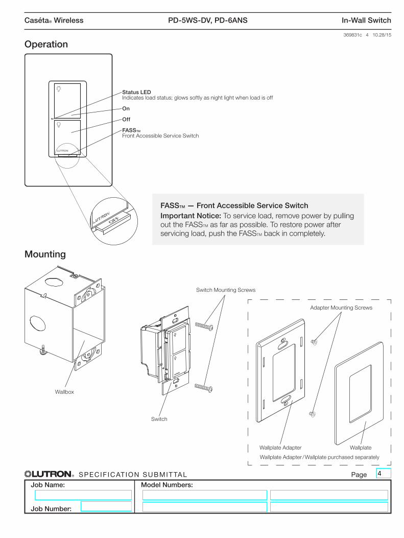
Mounting
Operation
FASSTM — Front Accessible Service SwitchImportant Notice: To service load, remove power by pulling out the FASSTM as far as possible. To restore power after servicing load, push the FASSTM back in completely.
Wallplate Adapter / Wallplate purchased separately
Wallplate Adapter Wallplate
Wallbox
Switch
Adapter Mounting Screws
Switch Mounting Screws
Status LEDIndicates load status; glows softly as night light when load is off
On
Off
FASSTM
Front Accessible Service Switch
PD-5WS-DV, PD-6ANS
® Specif icat ion Submittal page
Job Name:
Job Number:
Model Numbers:
Caséta® Wireless In-Wall Switch
369831c 5 10.28/15
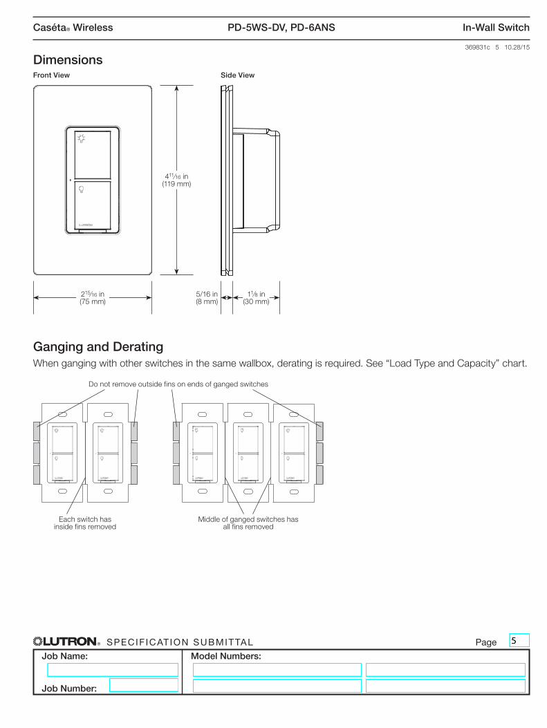
DimensionsFront View Side View
Ganging and DeratingWhen ganging with other switches in the same wallbox, derating is required. See “Load Type and Capacity” chart.
5/16 in(8 mm)
11⁄8 in(30 mm)
411⁄16 in(119 mm)
215⁄16 in(75 mm)
Each switch has inside fins removed
Middle of ganged switches has all fins removed
Do not remove outside fins on ends of ganged switches

PD-5WS-DV, PD-6ANS
® Specif icat ion Submittal page
Job Name:
Job Number:
Model Numbers:
Caséta® Wireless In-Wall Switch
369831c 6 10.28/15
Wiring Diagrams
1 When using controls without a mechanical 3-way switch, cap the blue terminal. Do not connect the blue wire to any other wiring or to ground.2 A LUT-MLC ensures proper function when LED, fluorescent, or ELV loads are used. Install the LUT-MLC inside a load fixture or in a separate junction box
within the circuit. 3 The red wire must be connected to the load and the black wire must be connected to Line/Hot. The switch will not work if the wires are reversed.
Single Location Installation
PD-5WS-DV
PD-6ANS
PD-5WS-DV
PD-6ANS
LUT-MLC 2Load
Load
Line/Hot
Line/Hot
Neutral
Neutral
Green
Green
Ground
Ground
Black
Black
Black
Red 3
Blue 1
Blue 1
120 / 277 V~ 50/60 Hz
120 V~ 50/60 Hz
(continued on next page…)
White
PD-5WS-DV, PD-6ANS
® Specif icat ion Submittal page
Job Name:
Job Number:
Model Numbers:
Caséta® Wireless In-Wall Switch
369831c 7 10.28/15
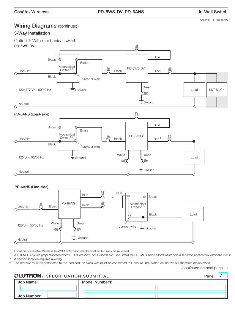
Wiring Diagrams (continued)
1 Location of Caséta® Wireless In-Wall Switch and mechanical switch may be reversed.2 A LUT-MLC ensures proper function when LED, fluorescent, or ELV loads are used. Install the LUT-MLC inside a load fixture or in a separate junction box within the circuit. 3 A second location requires rewiring.4 The red wire must be connected to the load and the black wire must be connected to Line/Hot. The switch will not work if the wires are reversed.
3-Way Installation
Option 1: With mechanical switch
(continued on next page…)
PD-5WS-DV 1Mechanical Switch 1, 3
BrassBrass
LUT-MLC 2Load
Line/Hot
Neutral
GreenGround
Ground
Black Black
Blue
120 / 277 V~ 50/60 Hz
BlackJumper wire
PD-5WS-DV
PD-6ANS 1Mechanical Switch 1, 3
BrassBrass
Load
Line/Hot
Neutral
GreenWhiteGround
Ground
Black Red 4
Blue
120 V~ 50/60 Hz
BlackJumper wire
PD-6ANS (Load-side)
Ground
GreenWhite
Line/Hot
Neutral
120 V~ 50/60 Hz
Black Red 4
Blue Brass
Jumper wire
Black
Brass
Load
PD-6ANS 1
PD-6ANS (Line-side)
Mechanical Switch 1, 3
Ground
PD-5WS-DV, PD-6ANS
® Specif icat ion Submittal page
Job Name:
Job Number:
Model Numbers:
Caséta® Wireless In-Wall Switch
369831c 8 10.28/15
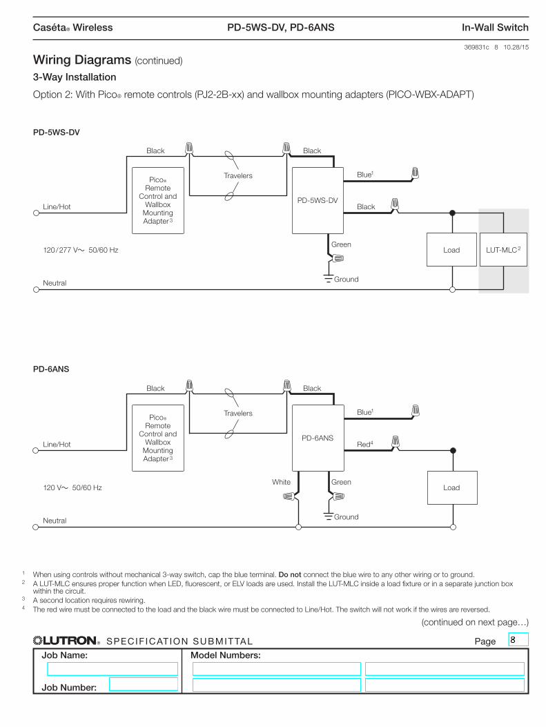
Wiring Diagrams (continued)
1 When using controls without mechanical 3-way switch, cap the blue terminal. Do not connect the blue wire to any other wiring or to ground.2 A LUT-MLC ensures proper function when LED, fluorescent, or ELV loads are used. Install the LUT-MLC inside a load fixture or in a separate junction box
within the circuit. 3 A second location requires rewiring.4 The red wire must be connected to the load and the black wire must be connected to Line/Hot. The switch will not work if the wires are reversed.
3-Way Installation
Option 2: With Pico® remote controls (PJ2-2B-xx) and wallbox mounting adapters (PICO-WBX-ADAPT)
(continued on next page…)
Black
Black
Black
Black
PD-5WS-DV
PD-6ANS
Pico® Remote
Control and Wallbox
Mounting Adapter 3
Pico® Remote
Control and Wallbox
Mounting Adapter 3
LUT-MLC 2Load
Load
Line/Hot
Line/Hot
Neutral
Neutral
Green
GreenWhite
Ground
Ground
Black
Red4
Blue1
Blue1
120 / 277 V~ 50/60 Hz
120 V~ 50/60 Hz
Travelers
Travelers
PD-5WS-DV
PD-6ANS
PD-5WS-DV, PD-6ANS
® Specif icat ion Submittal page
Job Name:
Job Number:
Model Numbers:
Caséta® Wireless In-Wall Switch
369831c 9 10.28/15
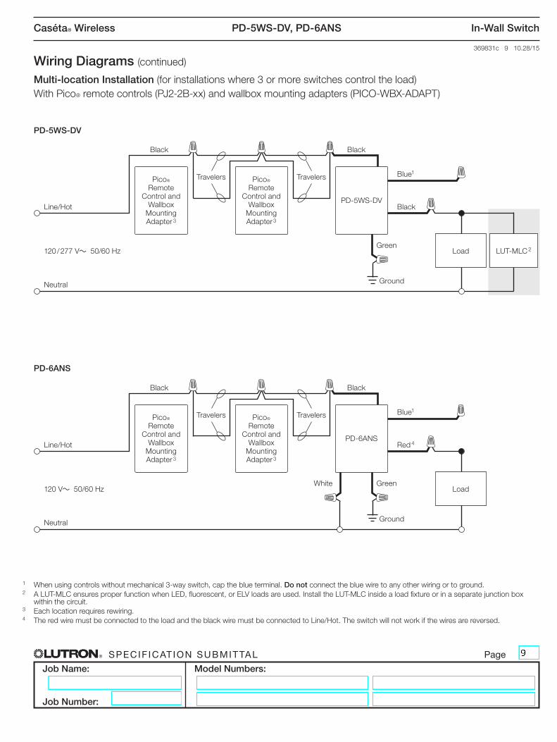
Wiring Diagrams (continued)
1 When using controls without mechanical 3-way switch, cap the blue terminal. Do not connect the blue wire to any other wiring or to ground.2 A LUT-MLC ensures proper function when LED, fluorescent, or ELV loads are used. Install the LUT-MLC inside a load fixture or in a separate junction box
within the circuit. 3 Each location requires rewiring.4 The red wire must be connected to the load and the black wire must be connected to Line/Hot. The switch will not work if the wires are reversed.
Multi-location Installation (for installations where 3 or more switches control the load)With Pico® remote controls (PJ2-2B-xx) and wallbox mounting adapters (PICO-WBX-ADAPT)
Pico® Remote
Control and Wallbox
Mounting Adapter 3
Pico® Remote
Control and Wallbox
Mounting Adapter 3
Pico® Remote
Control and Wallbox
Mounting Adapter 3
Pico® Remote
Control and Wallbox
Mounting Adapter 3
PD-6ANS
PD-5WS-DV
LUT-MLC 2
Load
Load
Line/Hot
Line/Hot
Neutral
Neutral
GreenWhite
Green
Ground
Ground
Red 4
Black
Black
Black
Black
Black
Blue1
Blue1
120 V~ 50/60 Hz
120 / 277 V~ 50/60 Hz
Travelers
Travelers
Travelers
Travelers
PD-5WS-DV
PD-6ANS
PD-5WS-DV, PD-6ANS
® Specif icat ion Submittal page
Job Name:
Job Number:
Model Numbers:
Caséta® Wireless In-Wall Switch
369831c 10 10.28/15
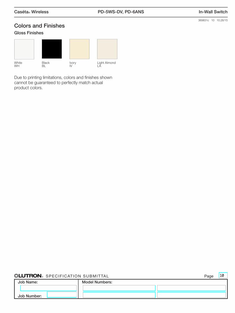
Colors and FinishesGloss Finishes
Due to printing limitations, colors and finishes shown cannot be guaranteed to perfectly match actual product colors.
WhiteWH
BlackBL
IvoryIV
Light AlmondLA