Embed Size (px)
Citation preview
CAST STEEL VALVES 3
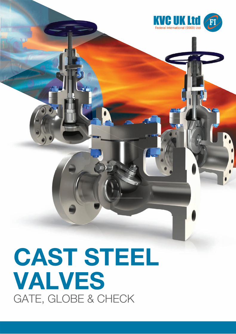
CAST STEEL VALVESGATE, GLOBE & CHECK
4 CAST STEEL VALVES
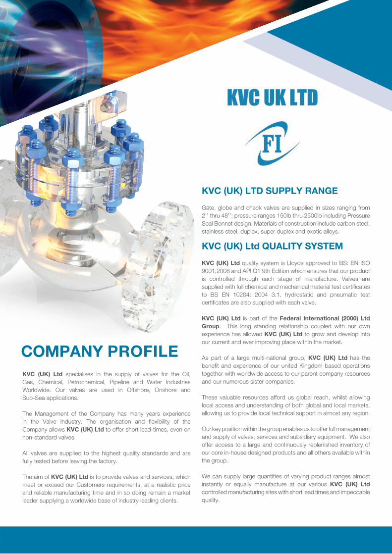
KVC (UK) Ltd specialises in the supply of valves for the Oil, Gas, Chemical, Petrochemical, Pipeline and Water Industries Worldwide. Our valves are used in Offshore, Onshore and Sub-Sea applications. The Management of the Company has many years experience in the Valve Industry. The organisation and fl exibility of the Company allows KVC (UK) Ltd to offer short lead-times, even on non-standard valves.
All valves are supplied to the highest quality standards and are fully tested before leaving the factory. The aim of KVC (UK) Ltd is to provide valves and services, which meet or exceed our Customers requirements, at a realistic price and reliable manufacturing time and in so doing remain a market leader supplying a worldwide base of industry leading clients.
COMPANY PROFILE
KVC (UK) LTD SUPPLY RANGE
Gate, globe and check valves are supplied in sizes ranging from2’’ thru 48’’; pressure ranges 150lb thru 2500lb including Pressure Seal Bonnet design. Materials of construction include carbon steel, stainless steel, duplex, super duplex and exotic alloys.
KVC (UK) Ltd QUALITY SYSTEM
KVC (UK) Ltd quality system is Lloyds approved to BS: EN ISO 9001,2008 and API Q1 9th Edition which ensures that our product is controlled through each stage of manufacture. Valves are supplied with full chemical and mechanical material test certifi cates to BS EN 10204: 2004 3.1. hydrostatic and pneumatic test certifi cates are also supplied with each valve. KVC (UK) Ltd is part of the Federal International (2000) Ltd Group. This long standing relationship coupled with our own experience has allowed KVC (UK) Ltd to grow and develop into our current and ever improving place within the market. As part of a large multi-national group, KVC (UK) Ltd has the benefi t and experience of our united Kingdom based operations together with worldwide access to our parent company resources and our numerous sister companies. These valuable resources afford us global reach, whilst allowing local access and understanding of both global and local markets, allowing us to provide local technical support in almost any region. Our key position within the group enables us to offer full management and supply of valves, services and subsidiary equipment. We also offer access to a large and continuously replenished inventory of our core in-house designed products and all others available within the group. We can supply large quantities of varying product ranges almost instantly or equally manufacture at our various KVC (UK) Ltd controlled manufacturing sites with short lead times and impeccable quality.
CAST STEEL VALVES 1
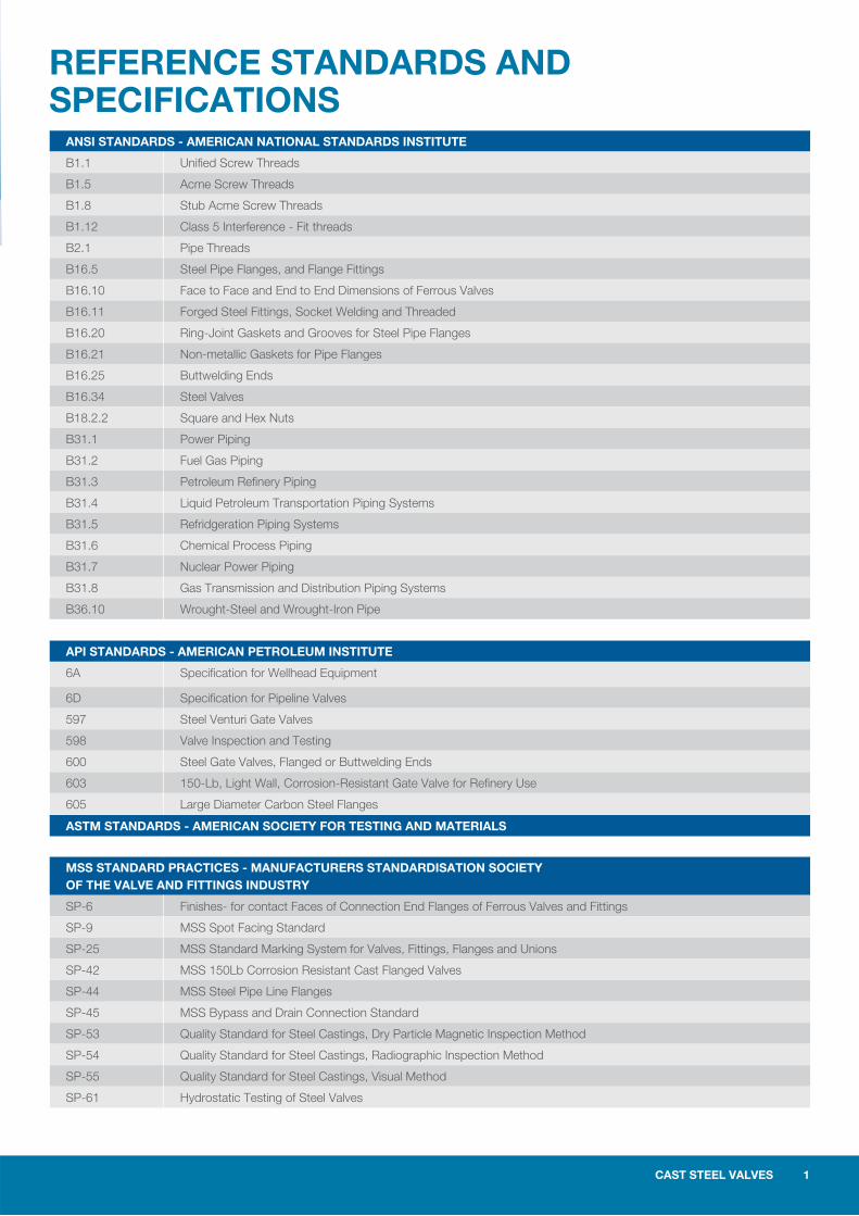
REFERENCE STANDARDS AND SPECIFICATIONS
ANSI STANDARDS - AMERICAN NATIONAL STANDARDS INSTITUTE
B1.1 Unified Screw Threads
B1.5 Acme Screw Threads
B1.8 Stub Acme Screw Threads
B1.12 Class 5 Interference - Fit threads
B2.1 Pipe Threads
B16.5 Steel Pipe Flanges, and Flange Fittings
B16.10 Face to Face and End to End Dimensions of Ferrous Valves
B16.11 Forged Steel Fittings, Socket Welding and Threaded
B16.20 Ring-Joint Gaskets and Grooves for Steel Pipe Flanges
B16.21 Non-metallic Gaskets for Pipe Flanges
B16.25 Buttwelding Ends
B16.34 Steel Valves
B18.2.2 Square and Hex Nuts
B31.1 Power Piping
B31.2 Fuel Gas Piping
B31.3 Petroleum Refinery Piping
B31.4 Liquid Petroleum Transportation Piping Systems
B31.5 Refridgeration Piping Systems
B31.6 Chemical Process Piping
B31.7 Nuclear Power Piping
B31.8 Gas Transmission and Distribution Piping Systems
B36.10 Wrought-Steel and Wrought-Iron Pipe
API STANDARDS - AMERICAN PETROLEUM INSTITUTE
6A Specification for Wellhead Equipment
6D Specification for Pipeline Valves
597 Steel Venturi Gate Valves
598 Valve Inspection and Testing
600 Steel Gate Valves, Flanged or Buttwelding Ends
603 150-Lb, Light Wall, Corrosion-Resistant Gate Valve for Refinery Use
605 Large Diameter Carbon Steel Flanges
ASTM STANDARDS - AMERICAN SOCIETY FOR TESTING AND MATERIALS
MSS STANDARD PRACTICES - MANUFACTURERS STANDARDISATION SOCIETY OF THE VALVE AND FITTINGS INDUSTRY
SP-6 Finishes- for contact Faces of Connection End Flanges of Ferrous Valves and Fittings
SP-9 MSS Spot Facing Standard
SP-25 MSS Standard Marking System for Valves, Fittings, Flanges and Unions
SP-42 MSS 150Lb Corrosion Resistant Cast Flanged Valves
SP-44 MSS Steel Pipe Line Flanges
SP-45 MSS Bypass and Drain Connection Standard
SP-53 Quality Standard for Steel Castings, Dry Particle Magnetic Inspection Method
SP-54 Quality Standard for Steel Castings, Radiographic Inspection Method
SP-55 Quality Standard for Steel Castings, Visual Method
SP-61 Hydrostatic Testing of Steel Valves
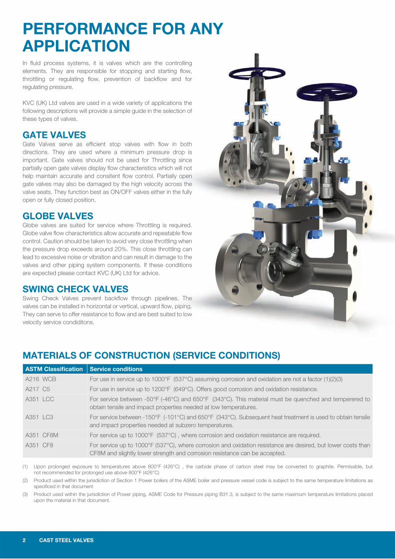
PERFORMANCE FOR ANY APPLICATIONIn fl uid process systems, it is valves which are the controlling elements. They are responsible for stopping and starting fl ow, throttling or regulating fl ow, prevention of backfl ow and for regulating pressure.
KVC (UK) Ltd valves are used in a wide variety of applications the following descriptions will provide a simple guide in the selection of these types of valves.
GATE VALVESGate Valves serve as effi cient stop valves with fl ow in both directions. They are used where a minimum pressure drop is important. Gate valves should not be used for Throttling since partially open gate valves display fl ow characteristics which will not help maintain accurate and consitent fl ow control. Partially open gate valves may also be damaged by the high velocity across the valve seats. They function best as ON/OFF valves either in the fully open or fully closed position.
GLOBE VALVESGlobe valves are suited for service where Throttling is required. Globe valve fl ow characteristics allow accurate and repeatable fl ow control. Caution should be taken to avoid very close throttling when the pressure drop exceeds around 20%. This close throttling can lead to excessive noise or vibration and can result in damage to the valves and other piping system components. If these conditions are expected please contact KVC (UK) Ltd for advice.
SWING CHECK VALVESSwing Check Valves prevent backfl ow through pipelines. The valves can be installed in horizontal or vertical, upward fl ow, piping. They can serve to offer resistance to fl ow and are best suited to low velocity service condiditons.
(1) Upon prolonged exposure to temperatures above 800°F (426°C) , the carbide phase of carbon steel may be converted to graphite. Permissible, but not recommended for prolonged use above 800°F (426°C)
(2) Product used within the jurisdiction of Section 1 Power boilers of the ASME boiler and pressure vessel code is subject to the same temperature limitations as specifi ced in that document
(3) Product used within the jurisdiction of Power piping, ASME Code for Pressure piping B31.3, is subject to the same maximum temperature limitations placed upon the material in that document.
MATERIALS OF CONSTRUCTION (SERVICE CONDITIONS)ASTM Classifi cation Service conditions
A216 WCB For use in service up to 1000°F (537°C) assuming corrosion and oxidation are not a factor (1)(2)(3)
A217 C5 For use in service up to 1200°F (649°C). Offers good corrosion and oxidation resistance.
A351 LCC For service between -50°F (-46°C) and 650°F (343°C). This material must be quenched and temperered to obtain tensile and impact properties needed at low temperatures.
A351 LC3 For service between -150°F (-101°C) and 650°F (343°C). Subsequent heat treatment is used to obtain tensile and impact properties needed at subzero temperatures.
A351 CF8M For service up to 1000°F (537°C) , where corrosion and oxidation resistance are required.
A351 CF8 For service up to 1000°F (537°C), where corrosion and oxidation resistance are desired, but lower costs than CF8M and slightly lower strength and corrosion resistance can be accepted.
the fully
equired. ble fl ow
ng when ing can e to the nditions
es.s. TTThhehehee pipipiipinggngng.d to low
2 CAST STEEL VALVES
CAST STEEL VALVES 3
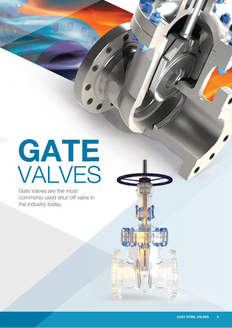
GATE VALVESGate Valves are the most commonly used shut-off valve in the industry today.
4 CAST STEEL VALVES
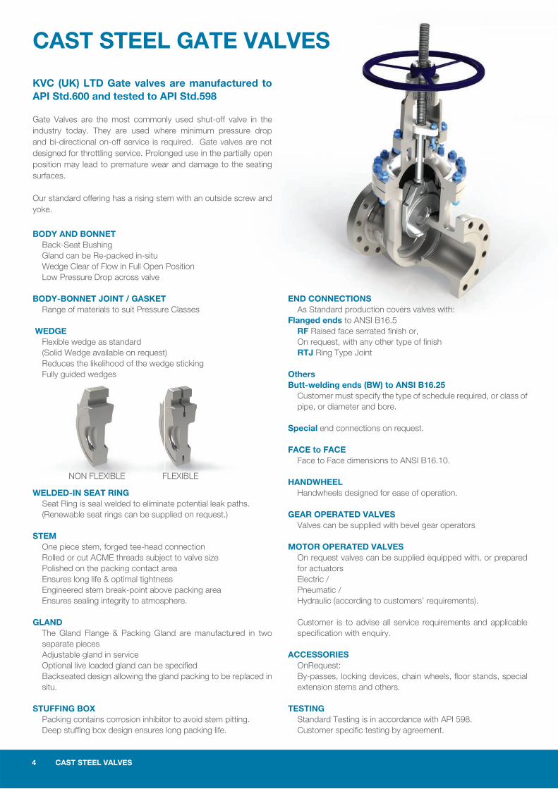
CAST STEEL GATE VALVES
KVC (UK) LTD Gate valves are manufactured to API Std.600 and tested to API Std.598
Gate Valves are the most commonly used shut-off valve in the industry today. They are used where minimum pressure drop and bi-directional on-off service is required. Gate valves are not designed for throttling service. Prolonged use in the partially open position may lead to premature wear and damage to the seating surfaces.
Our standard offering has a rising stem with an outside screw and yoke.
BODY AND BONNET Back-Seat Bushing Gland can be Re-packed in-situ Wedge Clear of Flow in Full Open Position Low Pressure Drop across valve
BODY-BONNET JOINT / GASKET Range of materials to suit Pressure Classes
WEDGE Flexible wedge as standard (Solid Wedge available on request) Reduces the likelihood of the wedge sticking Fully guided wedges
WELDED-IN SEAT RING Seat Ring is seal welded to eliminate potential leak paths. (Renewable seat rings can be supplied on request.)
STEM One piece stem, forged tee-head connection Rolled or cut ACME threads subject to valve size Polished on the packing contact area Ensures long life & optimal tightness Engineered stem break-point above packing area Ensures sealing integrity to atmosphere.
GLAND The Gland Flange & Packing Gland are manufactured in two separate pieces Adjustable gland in service Optional live loaded gland can be specifi ed Backseated design allowing the gland packing to be replaced in situ.
STUFFING BOX Packing contains corrosion inhibitor to avoid stem pitting. Deep stuffi ng box design ensures long packing life.
END CONNECTIONS As Standard production covers valves with:Flanged ends to ANSI B16.5 RF Raised face serrated fi nish or, On request, with any other type of fi nish RTJ Ring Type Joint
OthersButt-welding ends (BW) to ANSI B16.25 Customer must specify the type of schedule required, or class of pipe, or diameter and bore. Special end connections on request.
FACE to FACE Face to Face dimensions to ANSI B16.10.
HANDWHEEL Handwheels designed for ease of operation.
GEAR OPERATED VALVES Valves can be supplied with bevel gear operators
MOTOR OPERATED VALVES On request valves can be supplied equipped with, or prepared for actuators Electric / Pneumatic / Hydraulic (according to customers’ requirements).
Customer is to advise all service requirements and applicable specifi cation with enquiry.
ACCESSORIES OnRequest: By-passes, locking devices, chain wheels, fl oor stands, special extension stems and others.
TESTING Standard Testing is in accordance with API 598. Customer specifi c testing by agreement.
NON FLEXIBLE FLEXIBLE
CAST STEEL VALVES 5
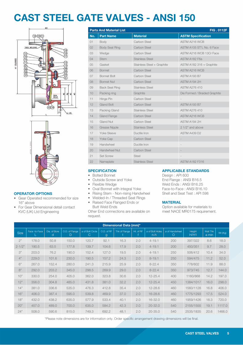
CAST STEEL GATE VALVES - ANSI 150
SPECIFICATION • Bolted Bonnet • Outside Screw and Yoke • Flexible Wedge • Oval Bonnet with integral Yoke • Rising Stem - Non-rising Handwheel • Welded-In / Threaded Seat Rings • Raised Face Flanged Ends or Butt Weld Ends Other End connections are available on request.
APPLICABLE STANDARDS Design : API 600 End Flange : ANSI B16.5Weld Ends : ANSI B16.25Face-to-Face : ANSI B16.10Shell and Seat Test : API 598
MATERIAL Option available for materials to meet NACE MR0175 requirement.
Parts And Material List FIG . 0112F
No. Part Name Material ASTM Specification
01 Body Carbon Steel ASTM A216 WCB
02 Body Seat Ring Carbon Steel ASTM A105 ST’L No. 6 Face
03 Wedge Carbon Steel ASTM A216 WCB 13Cr Face
04 Stem Stainless Steel ASTM A182 F6a
05 Gasket Stainless Steel + Graphite ASTM A182 316 + Graphite
06 Bonnet Carbon Steel ASTM A216 WCB
07 Bonnet Bolt Carbon Steel ASTM A193 B7
08 Bonnet Nut Carbon Steel ASTM A194 2H
09 Back Seat Ring Stainless Steel ASTM A276 410
10 Packing ring Graphite Die Formed / Braided Graphite
11 Hinge Pin Carbon Steel -
12 Gland Bolt Carbon Steel ASTM A193 B7
13 Packing Gland Stainless Steel ASTM A276 410
14 Gland Flange Carbon Steel ASTM A216 WCB
15 Gland Nut Carbon Steel ASTM A194 2H
16 Grease Nipple Stainless Steel 2 1/2” and above
17 Yoke Sleeve Ductile Iron ASTM A439 D2
18 Yoke Cap Carbon Steel -
19 Handwheel Ductile Iron -
20 Handwheel Nut Carbon Steel -
21 Set Screw Steel -
22 Nameplate Stainless Steel ASTM A182 F316
OPERATOR OPTIONS • Gear Operated recommended for size 16” above • For Gear Dimensional detail contact KVC (UK) Ltd Engineering
CAST STEEL VALVES 5
*Please note dimensions are for information only. Order specifi c arrangement drawing dimensions will be fi nal.
Dimensional Data (mm)*
Size Face -to-Face L
Dia. of Bore d
O.D. of Flange D
ø of Bolt Circle C
O.D. of RF g
Thk of Flange t
Ht. of RF f
ø of Bolt Holes n-h
ø of Handwheel O
Height H/H1
Wall Thk a min
Wt (Kg)
2” 178.0 50.8 150.0 120.7 92.1 16.3 2.0 4-19.1 200 397/322 8.6 18.0
2-1/2” 190.5 63.5 177.8 139.7 104.6 17.9 2.0 4-19.1 200 450/351 9.7 28.0
3” 203.0 76.2 190.0 152.4 127.0 19.5 2.0 4-19.1 250 506/412 10.4 34.0
4” 229.0 101.6 230.0 190.5 157.2 24.3 2.0 8-19.1 250 594/475 11.2 52.0
6” 267.0 152.4 280.0 241.3 215.9 25.9 2.0 8-22.4 350 778/602 11.9 88.0
8” 292.0 203.2 345.0 298.5 269.9 29.0 2.0 8-22.4 350 973/745 12.7 144.0
10” 330.0 254.0 405.0 362.0 323.8 30.6 2.0 12-25.4 400 1160/868 14.2 197.0
12” 356.0 304.8 485.0 431.8 381.0 32.2 2.0 12-25.4 450 1384/1017 16.0 298.0
14” 381.0 336.6 535.0 476.3 412.8 35.4 2.0 12-28.6 460 1560/1128 16.8 406.0
16” 406.0 387.4 595.0 539.8 469.9 37.0 2.0 16-28.6 460 1775/1293 17.5 524.0
18” 432.0 438.2 635.0 577.9 533.4 40.1 2.0 16-32.0 460 1959/1426 18.3 720.0
20” 457.0 489.0 700.0 635.0 584.2 42.3 2.0 20-32.0 540 2155/1555 19.1 1117.0
24” 508.0 590.6 815.0 749.3 692.2 48.1 2.0 20-35.0 540 2535/1835 20.6 1466.0
6 CAST STEEL VALVES
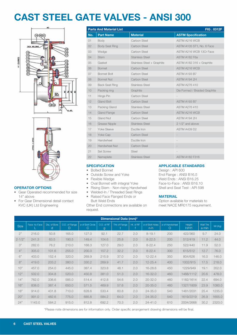
CAST STEEL GATE VALVES - ANSI 300
SPECIFICATION • Bolted Bonnet • Outside Screw and Yoke • Flexible Wedge • Oval Bonnet with integral Yoke • Rising Stem - Non-rising Handwheel • Welded-In / Threaded Seat Rings • Raised Face Flanged Ends or Butt Weld Ends Other End connections are available on request.
APPLICABLE STANDARDS Design : API 600 End Flange : ANSI B16.5Weld Ends : ANSI B16.25Face-to-Face : ANSI B16.10Shell and Seat Test : API 598
MATERIAL Option available for materials to meet NACE MR0175 requirement.
Parts And Material List FIG . 0312F
No. Part Name Material ASTM Specification
01 Body Carbon Steel ASTM A216 WCB
02 Body Seat Ring Carbon Steel ASTM A105 ST’L No. 6 Face
03 Wedge Carbon Steel ASTM A216 WCB 13Cr Face
04 Stem Stainless Steel ASTM A182 F6a
05 Gasket Stainless Steel + Graphite ASTM A182 316 + Graphite
06 Bonnet Carbon Steel ASTM A216 WCB
07 Bonnet Bolt Carbon Steel ASTM A193 B7
08 Bonnet Nut Carbon Steel ASTM A194 2H
09 Back Seat Ring Stainless Steel ASTM A276 410
10 Packing ring Graphite Die Formed / Braided Graphite
11 Hinge Pin Carbon Steel -
12 Gland Bolt Carbon Steel ASTM A193 B7
13 Packing Gland Stainless Steel ASTM A276 410
14 Gland Flange Carbon Steel ASTM A216 WCB
15 Gland Nut Carbon Steel ASTM A194 2H
16 Grease Nipple Stainless Steel 2 1/2” and above
17 Yoke Sleeve Ductile Iron ASTM A439 D2
18 Yoke Cap Carbon Steel -
19 Handwheel Ductile Iron -
20 Handwheel Nut Carbon Steel -
21 Set Screw Steel -
22 Nameplate Stainless Steel ASTM A182 F316
OPERATOR OPTIONS • Gear Operated recommended for size 14” above • For Gear Dimensional detail contact KVC (UK) Ltd Engineering
Dimensional Data (mm)*
Size Face -to-Face L
Dia. of Bore d
O.D. of Flange D
ø of Bolt Circle C
O.D. of RF g
Thk of Flange t
Ht. of RF f
ø of Bolt Holes n-h
ø of Handwheel O
Height H/H1
Wall Thk a min
Wt (Kg)
2” 216.0 50.8 165.0 127.0 92.1 22.7 2.0 8-19.1 200 422/360 9.7 24.0
2-1/2” 241.3 63.5 190.5 149.4 104.6 25.8 2.0 8-22.5 200 512/419 11.2 44.0
3” 282.0 76.2 210.0 168.3 127.0 29.0 2.0 8-22.4 250 522/440 11.9 52.0
4” 305.0 101.6 255.0 200.0 157.2 32.2 2.0 8-22.4 300 615/512 12.7 76.0
6” 403.0 152.4 320.0 269.9 215.9 37.0 2.0 12-22.4 350 804/626 16.0 146.0
8” 419.0 203.2 380.0 330.2 269.9 41.7 2.0 12-25.4 400 1002/915 17.5 218.0
10” 457.0 254.0 445.0 387.4 323.8 48.1 2.0 16-28.6 450 1229/949 19.1 352.0
12” 502.0 304.8 520.0 450.8 381.0 51.3 2.0 16-32.0 460 1488/1112 20.6 478.0
14” 762.0 336.6 585.0 514.4 412.8 54.6 2.0 20-32.0 460 1182/1614 22.4 694.0
16” 838.0 387.4 650.0 571.5 469.9 57.6 2.0 20-35.0 460 1327/1809 23.9 1080.0
18” 914.0 431.8 710.0 628.6 533.4 60.8 2.0 24-35.0 540 1481/2031 25.4 1235.0
20” 991.0 482.6 775.0 685.8 584.2 64.0 2.0 24-35.0 540 1619/2219 26.9 1655.0
24” 1143.0 584.2 915.0 812.8 692.2 70.3 2.0 24-41.0 610 2004/2668 30.2 2320.0
*Please note dimensions are for information only. Order specifi c arrangement drawing dimensions will be fi nal.
CAST STEEL VALVES 7
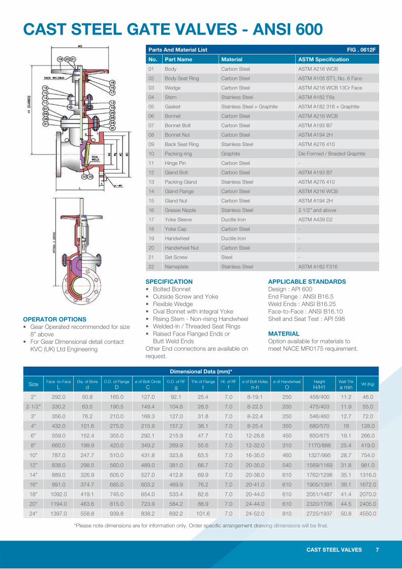
CAST STEEL GATE VALVES - ANSI 600
SPECIFICATION • Bolted Bonnet • Outside Screw and Yoke • Flexible Wedge • Oval Bonnet with integral Yoke • Rising Stem - Non-rising Handwheel • Welded-In / Threaded Seat Rings • Raised Face Flanged Ends or Butt Weld Ends Other End connections are available on request.
APPLICABLE STANDARDS Design : API 600 End Flange : ANSI B16.5Weld Ends : ANSI B16.25Face-to-Face : ANSI B16.10Shell and Seat Test : API 598
MATERIAL Option available for materials to meet NACE MR0175 requirement.
Parts And Material List FIG . 0612F
No. Part Name Material ASTM Specification
01 Body Carbon Steel ASTM A216 WCB
02 Body Seat Ring Carbon Steel ASTM A105 ST’L No. 6 Face
03 Wedge Carbon Steel ASTM A216 WCB 13Cr Face
04 Stem Stainless Steel ASTM A182 F6a
05 Gasket Stainless Steel + Graphite ASTM A182 316 + Graphite
06 Bonnet Carbon Steel ASTM A216 WCB
07 Bonnet Bolt Carbon Steel ASTM A193 B7
08 Bonnet Nut Carbon Steel ASTM A194 2H
09 Back Seat Ring Stainless Steel ASTM A276 410
10 Packing ring Graphite Die Formed / Braided Graphite
11 Hinge Pin Carbon Steel -
12 Gland Bolt Carbon Steel ASTM A193 B7
13 Packing Gland Stainless Steel ASTM A276 410
14 Gland Flange Carbon Steel ASTM A216 WCB
15 Gland Nut Carbon Steel ASTM A194 2H
16 Grease Nipple Stainless Steel 2 1/2” and above
17 Yoke Sleeve Ductile Iron ASTM A439 D2
18 Yoke Cap Carbon Steel -
19 Handwheel Ductile Iron -
20 Handwheel Nut Carbon Steel -
21 Set Screw Steel -
22 Nameplate Stainless Steel ASTM A182 F316
OPERATOR OPTIONS • Gear Operated recommended for size 8” above • For Gear Dimensional detail contact KVC (UK) Ltd Engineering
*Please note dimensions are for information only. Order specifi c arrangement drawing dimensions will be fi nal.
CAST STEEL VALVES 7
awing dimensions will be fi nal.
Dimensional Data (mm)*
Size Face -to-Face L
Dia. of Bore d
O.D. of Flange D
ø of Bolt Circle C
O.D. of RF g
Thk of Flange t
Ht. of RF f
ø of Bolt Holes n-h
ø of Handwheel O
Height H/H1
Wall Thk a min
Wt (Kg)
2” 292.0 50.8 165.0 127.0 92.1 25.4 7.0 8-19.1 250 458/400 11.2 46.0
2-1/2” 330.2 63.5 190.5 149.4 104.6 28.5 7.0 8-22.5 250 475/403 11.9 55.0
3” 356.0 76.2 210.0 168.3 127.0 31.8 7.0 8-22.4 250 546/460 12.7 72.0
4” 432.0 101.6 275.0 215.9 157.2 38.1 7.0 8-25.4 350 680/570 16 128.0
6” 559.0 152.4 355.0 292.1 215.9 47.7 7.0 12-28.6 450 850/675 19.1 266.0
8” 660.0 199.9 420.0 349.2 269.9 55.6 7.0 12-32.0 310 1170/888 25.4 419.0
10” 787.0 247.7 510.0 431.8 323.8 63.5 7.0 16-35.0 460 1327/995 28.7 754.0
12” 838.0 298.5 560.0 489.0 381.0 66.7 7.0 20-35.0 540 1569/1169 31.8 981.0
14” 889.0 326.9 605.0 527.0 412.8 69.9 7.0 20-38.0 610 1762/1298 35.1 1316.0
16” 991.0 374.7 685.0 603.2 469.9 76.2 7.0 20-41.0 610 1905/1391 38.1 1672.0
18” 1092.0 419.1 745.0 654.0 533.4 82.6 7.0 20-44.0 610 2051/1487 41.4 2070.0
20” 1194.0 463.6 815.0 723.9 584.2 88.9 7.0 24-44.0 610 2320/1706 44.5 2405.0
24” 1397.0 558.8 939.8 838.2 692.2 101.6 7.0 24-52.0 810 2725/1937 50.8 4550.0
8 CAST STEEL VALVES
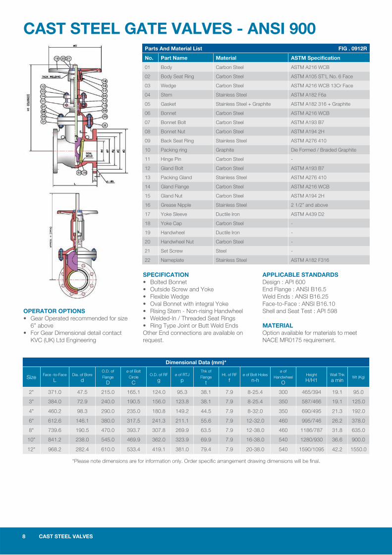
CAST STEEL GATE VALVES - ANSI 900
SPECIFICATION • Bolted Bonnet • Outside Screw and Yoke • Flexible Wedge • Oval Bonnet with integral Yoke • Rising Stem - Non-rising Handwheel • Welded-In / Threaded Seat Rings • Ring Type Joint or Butt Weld Ends Other End connections are available on request.
APPLICABLE STANDARDS Design : API 600 End Flange : ANSI B16.5Weld Ends : ANSI B16.25Face-to-Face : ANSI B16.10Shell and Seat Test : API 598
MATERIAL Option available for materials to meet NACE MR0175 requirement.
Parts And Material List FIG . 0912R
No. Part Name Material ASTM Specification
01 Body Carbon Steel ASTM A216 WCB
02 Body Seat Ring Carbon Steel ASTM A105 ST’L No. 6 Face
03 Wedge Carbon Steel ASTM A216 WCB 13Cr Face
04 Stem Stainless Steel ASTM A182 F6a
05 Gasket Stainless Steel + Graphite ASTM A182 316 + Graphite
06 Bonnet Carbon Steel ASTM A216 WCB
07 Bonnet Bolt Carbon Steel ASTM A193 B7
08 Bonnet Nut Carbon Steel ASTM A194 2H
09 Back Seat Ring Stainless Steel ASTM A276 410
10 Packing ring Graphite Die Formed / Braided Graphite
11 Hinge Pin Carbon Steel -
12 Gland Bolt Carbon Steel ASTM A193 B7
13 Packing Gland Stainless Steel ASTM A276 410
14 Gland Flange Carbon Steel ASTM A216 WCB
15 Gland Nut Carbon Steel ASTM A194 2H
16 Grease Nipple Stainless Steel 2 1/2” and above
17 Yoke Sleeve Ductile Iron ASTM A439 D2
18 Yoke Cap Carbon Steel -
19 Handwheel Ductile Iron -
20 Handwheel Nut Carbon Steel -
21 Set Screw Steel -
22 Nameplate Stainless Steel ASTM A182 F316
OPERATOR OPTIONS • Gear Operated recommended for size 6” above • For Gear Dimensional detail contact KVC (UK) Ltd Engineering
Dimensional Data (mm)*
Size Face -to-Face L
Dia. of Bore d
O.D. of
Flange D
ø of Bolt
Circle C
O.D. of RF g
ø of RTJ p
Thk of
Flange t
Ht. of RF f
ø of Bolt Holes n-h
ø of
Handwheel O
Height H/H1
Wall Thk a min
Wt (Kg)
2" 371.0 47.5 215.0 165.1 124.0 95.3 38.1 7.9 8-25.4 300 465/394 19.1 95.0
3" 384.0 72.9 240.0 190.5 156.0 123.8 38.1 7.9 8-25.4 350 587/466 19.1 125.0
4" 460.2 98.3 290.0 235.0 180.8 149.2 44.5 7.9 8-32.0 350 690/495 21.3 192.0
6" 612.6 146.1 380.0 317.5 241.3 211.1 55.6 7.9 12-32.0 460 995/746 26.2 378.0
8" 739.6 190.5 470.0 393.7 307.8 269.9 63.5 7.9 12-38.0 460 1186/787 31.8 635.0
10" 841.2 238.0 545.0 469.9 362.0 323.9 69.9 7.9 16-38.0 540 1280/930 36.6 900.0
12" 968.2 282.4 610.0 533.4 419.1 381.0 79.4 7.9 20-38.0 540 1590/1095 42.2 1550.0
*Please note dimensions are for information only. Order specifi c arrangement drawing dimensions will be fi nal.
CAST STEEL VALVES 9
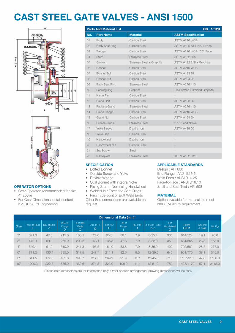
CAST STEEL GATE VALVES - ANSI 1500
SPECIFICATION • Bolted Bonnet • Outside Screw and Yoke • Flexible Wedge • Oval Bonnet with integral Yoke • Rising Stem - Non-rising Handwheel • Welded-In / Threaded Seat Rings • Ring Type Joint or Butt Weld Ends Other End connections are available on request.
APPLICABLE STANDARDS Design : API 600 End Flange : ANSI B16.5Weld Ends : ANSI B16.25Face-to-Face : ANSI B16.10Shell and Seat Test : API 598
MATERIAL Option available for materials to meet NACE MR0175 requirement.
Parts And Material List FIG . 1512R
No. Part Name Material ASTM Specification
01 Body Carbon Steel ASTM A216 WCB
02 Body Seat Ring Carbon Steel ASTM A105 ST’L No. 6 Face
03 Wedge Carbon Steel ASTM A216 WCB 13Cr Face
04 Stem Stainless Steel ASTM A182 F6a
05 Gasket Stainless Steel + Graphite ASTM A182 316 + Graphite
06 Bonnet Carbon Steel ASTM A216 WCB
07 Bonnet Bolt Carbon Steel ASTM A193 B7
08 Bonnet Nut Carbon Steel ASTM A194 2H
09 Back Seat Ring Stainless Steel ASTM A276 410
10 Packing ring Graphite Die Formed / Braided Graphite
11 Hinge Pin Carbon Steel -
12 Gland Bolt Carbon Steel ASTM A193 B7
13 Packing Gland Stainless Steel ASTM A276 410
14 Gland Flange Carbon Steel ASTM A216 WCB
15 Gland Nut Carbon Steel ASTM A194 2H
16 Grease Nipple Stainless Steel 2 1/2” and above
17 Yoke Sleeve Ductile Iron ASTM A439 D2
18 Yoke Cap Carbon Steel -
19 Handwheel Ductile Iron -
20 Handwheel Nut Carbon Steel -
21 Set Screw Steel -
22 Nameplate Stainless Steel ASTM A182 F316
OPERATOR OPTIONS • Gear Operated recommended for size 4” above • For Gear Dimensional detail contact KVC (UK) Ltd Engineering
*Please note dimensions are for information only. Order specifi c arrangement drawing dimensions will be fi nal.
CAST STEEL VALVES 9
Dimensional Data (mm)*
Size Face -to-Face L
Dia. of Bore d
O.D. of
Flange D
ø of Bolt
Circle C
O.D. of RF g
ø of RTJ P
Thk of
Flange t
Ht. of RF f
ø of Bolt Holes n-h
ø of
Handwheel O
Height H/H1
Wall Thk a min
Wt (Kg)
2" 371.3 47.5 215.0 165.1 124.0 95.3 38.1 7.9 8-25.4 300 614/524 19.1 95.0
3" 472.9 69.9 265.0 203.2 168.1 136.5 47.8 7.9 8-32.0 350 681/565 23.8 168.0
4" 549.1 91.9 310.0 241.3 193.5 161.9 53.8 7.9 8-35.0 400 702/582 28.5 277.0
6" 711.2 136.4 395.0 317.5 247.7 211.1 82.6 9.5 12-39.0 640 951/775 38.1 545.0
8" 841.5 177.8 485.0 393.7 317.5 269.9 91.9 11.1 12-45.0 710 1137/913 47.8 1180.0
10" 1000.3 222.3 585.0 482.6 371.3 323.9 108.0 11.1 12-51.0 750 1437/1170 57.1 2118.0
10 CAST STEEL VALVES
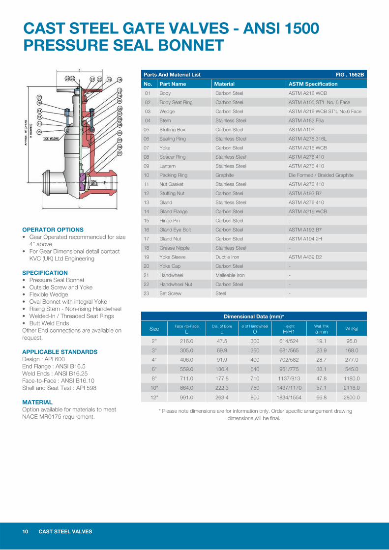
CAST STEEL GATE VALVES - ANSI 1500PRESSURE SEAL BONNET
OPERATOR OPTIONS • Gear Operated recommended for size 4” above • For Gear Dimensional detail contact KVC (UK) Ltd Engineering
SPECIFICATION • Pressure Seal Bonnet • Outside Screw and Yoke • Flexible Wedge• Oval Bonnet with integral Yoke • Rising Stem - Non-rising Handwheel• Welded-In / Threaded Seat Rings • Butt Weld Ends Other End connections are available on request.
APPLICABLE STANDARDS Design : API 600End Flange : ANSI B16.5Weld Ends : ANSI B16.25Face-to-Face : ANSI B16.10Shell and Seat Test : API 598
MATERIAL Option available for materials to meet NACE MR0175 requirement.
Parts And Material List FIG . 1552B
No. Part Name Material ASTM Specification
01 Body Carbon Steel ASTM A216 WCB
02 Body Seat Ring Carbon Steel ASTM A105 ST'L No. 6 Face
03 Wedge Carbon Steel ASTM A216 WCB ST'L No.6 Face
04 Stem Stainless Steel ASTM A182 F6a
05 Stuffing Box Carbon Steel ASTM A105
06 Sealing Ring Stainless Steel ASTM A276 316L
07 Yoke Carbon Steel ASTM A216 WCB
08 Spacer Ring Stainless Steel ASTM A276 410
09 Lantern Stainless Steel ASTM A276 410
10 Packing Ring Graphite Die Formed / Braided Graphite
11 Nut Gasket Stainless Steel ASTM A276 410
12 Stuffing Nut Carbon Steel ASTM A193 B7
13 Gland Stainless Steel ASTM A276 410
14 Gland Flange Carbon Steel ASTM A216 WCB
15 Hinge Pin Carbon Steel -
16 Gland Eye Bolt Carbon Steel ASTM A193 B7
17 Gland Nut Carbon Steel ASTM A194 2H
18 Grease Nipple Stainless Steel -
19 Yoke Sleeve Ductile Iron ASTM A439 D2
20 Yoke Cap Carbon Steel -
21 Handwheel Malleable Iron -
22 Handwheel Nut Carbon Steel -
23 Set Screw Steel -
Dimensional Data (mm)*
Size Face -to-Face L
Dia. of Bore d
ø of Handwheel O
Height H/H1
Wall Thk a min
Wt (Kg)
2" 216.0 47.5 300 614/524 19.1 95.0
3" 305.0 69.9 350 681/565 23.9 168.0
4" 406.0 91.9 400 702/582 28.7 277.0
6" 559.0 136.4 640 951/775 38.1 545.0
8" 711.0 177.8 710 1137/913 47.8 1180.0
10" 864.0 222.3 750 1437/1170 57.1 2118.0
12" 991.0 263.4 800 1834/1554 66.8 2800.0
* Please note dimensions are for information only. Order specifi c arrangement drawing dimensions will be fi nal.
CAST STEEL VALVES 11 CAST STEEL VALVES 11
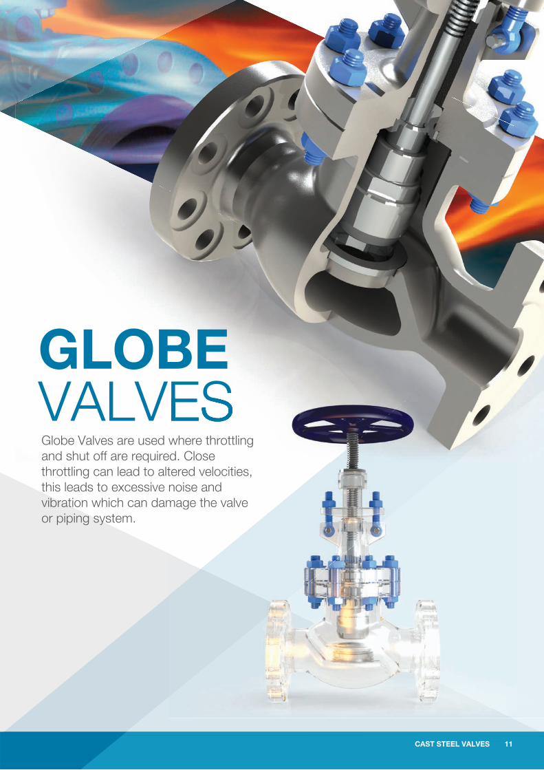
GLOBE VALVESGlobe Valves are used where throttling and shut off are required. Close throttling can lead to altered velocities, this leads to excessive noise and vibration which can damage the valve or piping system.
where throttling ed. Close tered velocities, noise andmage the valve
12 CAST STEEL VALVES
CAST STEEL GLOBE VALVES
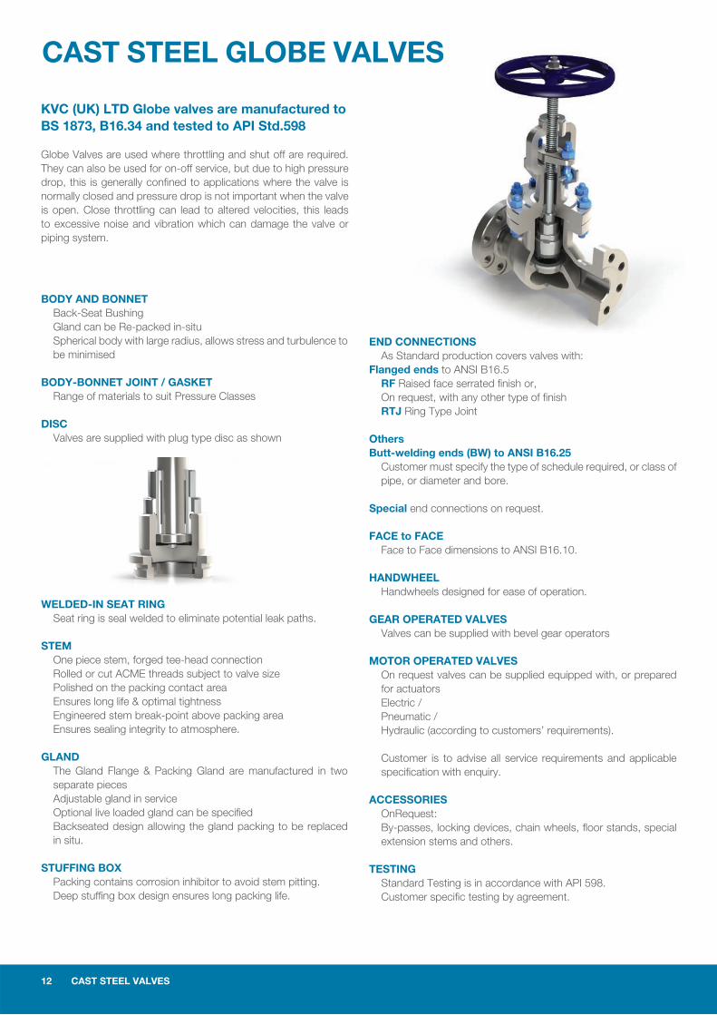
BODY AND BONNET Back-Seat Bushing Gland can be Re-packed in-situ Spherical body with large radius, allows stress and turbulence to be minimised
BODY-BONNET JOINT / GASKET Range of materials to suit Pressure Classes
DISC Valves are supplied with plug type disc as shown
WELDED-IN SEAT RING Seat ring is seal welded to eliminate potential leak paths.
STEM One piece stem, forged tee-head connection Rolled or cut ACME threads subject to valve size Polished on the packing contact area Ensures long life & optimal tightness Engineered stem break-point above packing area Ensures sealing integrity to atmosphere.
GLAND The Gland Flange & Packing Gland are manufactured in two separate pieces Adjustable gland in service Optional live loaded gland can be specifi ed Backseated design allowing the gland packing to be replaced in situ.
STUFFING BOX Packing contains corrosion inhibitor to avoid stem pitting. Deep stuffi ng box design ensures long packing life.
ES
END CONNECTIONS As Standard production covers valves with:Flanged ends to ANSI B16.5 RF Raised face serrated fi nish or, On request, with any other type of fi nish RTJ Ring Type Joint
OthersButt-welding ends (BW) to ANSI B16.25 Customer must specify the type of schedule required, or class of pipe, or diameter and bore.
Special end connections on request.
FACE to FACE Face to Face dimensions to ANSI B16.10.
HANDWHEEL Handwheels designed for ease of operation.
GEAR OPERATED VALVES Valves can be supplied with bevel gear operators
MOTOR OPERATED VALVES On request valves can be supplied equipped with, or prepared for actuators Electric / Pneumatic / Hydraulic (according to customers’ requirements).
Customer is to advise all service requirements and applicable specifi cation with enquiry.
ACCESSORIES OnRequest: By-passes, locking devices, chain wheels, fl oor stands, special extension stems and others.
TESTING Standard Testing is in accordance with API 598. Customer specifi c testing by agreement.
KVC (UK) LTD Globe valves are manufactured to BS 1873, B16.34 and tested to API Std.598
Globe Valves are used where throttling and shut off are required. They can also be used for on-off service, but due to high pressure drop, this is generally confi ned to applications where the valve is normally closed and pressure drop is not important when the valve is open. Close throttling can lead to altered velocities, this leads to excessive noise and vibration which can damage the valve or piping system.
CAST STEEL VALVES 13
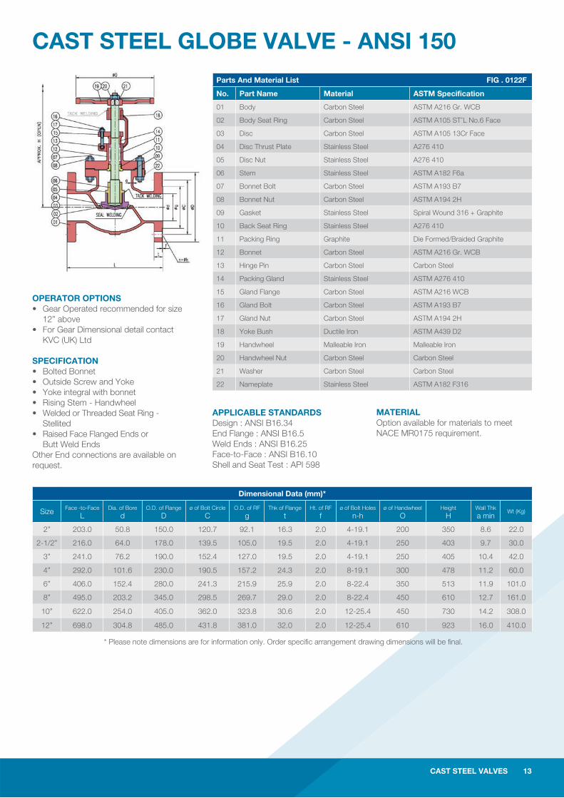
CAST STEEL GLOBE VALVE - ANSI 150Parts And Material List FIG . 0122F
No. Part Name Material ASTM Specification
01 Body Carbon Steel ASTM A216 Gr. WCB
02 Body Seat Ring Carbon Steel ASTM A105 ST’L No.6 Face
03 Disc Carbon Steel ASTM A105 13Cr Face
04 Disc Thrust Plate Stainless Steel A276 410
05 Disc Nut Stainless Steel A276 410
06 Stem Stainless Steel ASTM A182 F6a
07 Bonnet Bolt Carbon Steel ASTM A193 B7
08 Bonnet Nut Carbon Steel ASTM A194 2H
09 Gasket Stainless Steel Spiral Wound 316 + Graphite
10 Back Seat Ring Stainless Steel A276 410
11 Packing Ring Graphite Die Formed/Braided Graphite
12 Bonnet Carbon Steel ASTM A216 Gr. WCB
13 Hinge Pin Carbon Steel Carbon Steel
14 Packing Gland Stainless Steel ASTM A276 410
15 Gland Flange Carbon Steel ASTM A216 WCB
16 Gland Bolt Carbon Steel ASTM A193 B7
17 Gland Nut Carbon Steel ASTM A194 2H
18 Yoke Bush Ductile Iron ASTM A439 D2
19 Handwheel Malleable Iron Malleable Iron
20 Handwheel Nut Carbon Steel Carbon Steel
21 Washer Carbon Steel Carbon Steel
22 Nameplate Stainless Steel ASTM A182 F316
OPERATOR OPTIONS• Gear Operated recommended for size 12” above• For Gear Dimensional detail contact KVC (UK) Ltd
SPECIFICATION• Bolted Bonnet • Outside Screw and Yoke • Yoke integral with bonnet • Rising Stem - Handwheel• Welded or Threaded Seat Ring - Stellited • Raised Face Flanged Ends or Butt Weld EndsOther End connections are available on request.
MATERIALOption available for materials to meet NACE MR0175 requirement.
* Please note dimensions are for information only. Order specifi c arrangement drawing dimensions will be fi nal.
CAST STEEL VALVES 13
Dimensional Data (mm)*
Size Face -to-Face L
Dia. of Bore d
O.D. of Flange D
ø of Bolt Circle C
O.D. of RF g
Thk of Flange t
Ht. of RF f
ø of Bolt Holes n-h
ø of Handwheel O
Height H
Wall Thk a min
Wt (Kg)
2” 203.0 50.8 150.0 120.7 92.1 16.3 2.0 4-19.1 200 350 8.6 22.0
2-1/2” 216.0 64.0 178.0 139.5 105.0 19.5 2.0 4-19.1 250 403 9.7 30.0
3” 241.0 76.2 190.0 152.4 127.0 19.5 2.0 4-19.1 250 405 10.4 42.0
4” 292.0 101.6 230.0 190.5 157.2 24.3 2.0 8-19.1 300 478 11.2 60.0
6” 406.0 152.4 280.0 241.3 215.9 25.9 2.0 8-22.4 350 513 11.9 101.0
8” 495.0 203.2 345.0 298.5 269.7 29.0 2.0 8-22.4 450 610 12.7 161.0
10” 622.0 254.0 405.0 362.0 323.8 30.6 2.0 12-25.4 450 730 14.2 308.0
12” 698.0 304.8 485.0 431.8 381.0 32.0 2.0 12-25.4 610 923 16.0 410.0
APPLICABLE STANDARDSDesign : ANSI B16.34 End Flange : ANSI B16.5Weld Ends : ANSI B16.25Face-to-Face : ANSI B16.10Shell and Seat Test : API 598
14 CAST STEEL VALVES
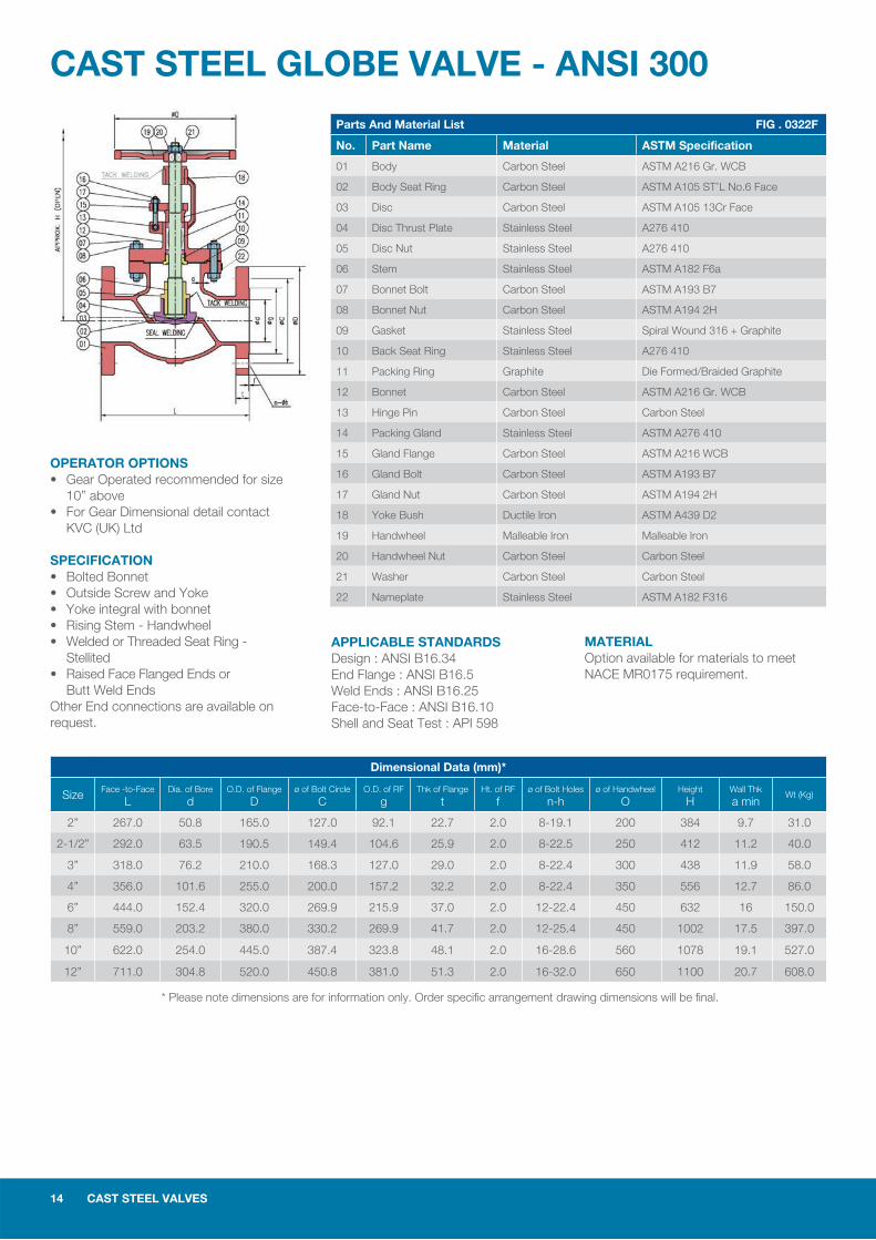
CAST STEEL GLOBE VALVE - ANSI 300Parts And Material List FIG . 0322F
No. Part Name Material ASTM Specification
01 Body Carbon Steel ASTM A216 Gr. WCB
02 Body Seat Ring Carbon Steel ASTM A105 ST’L No.6 Face
03 Disc Carbon Steel ASTM A105 13Cr Face
04 Disc Thrust Plate Stainless Steel A276 410
05 Disc Nut Stainless Steel A276 410
06 Stem Stainless Steel ASTM A182 F6a
07 Bonnet Bolt Carbon Steel ASTM A193 B7
08 Bonnet Nut Carbon Steel ASTM A194 2H
09 Gasket Stainless Steel Spiral Wound 316 + Graphite
10 Back Seat Ring Stainless Steel A276 410
11 Packing Ring Graphite Die Formed/Braided Graphite
12 Bonnet Carbon Steel ASTM A216 Gr. WCB
13 Hinge Pin Carbon Steel Carbon Steel
14 Packing Gland Stainless Steel ASTM A276 410
15 Gland Flange Carbon Steel ASTM A216 WCB
16 Gland Bolt Carbon Steel ASTM A193 B7
17 Gland Nut Carbon Steel ASTM A194 2H
18 Yoke Bush Ductile Iron ASTM A439 D2
19 Handwheel Malleable Iron Malleable Iron
20 Handwheel Nut Carbon Steel Carbon Steel
21 Washer Carbon Steel Carbon Steel
22 Nameplate Stainless Steel ASTM A182 F316
Dimensional Data (mm)*
Size Face -to-Face L
Dia. of Bore d
O.D. of Flange D
ø of Bolt Circle C
O.D. of RF g
Thk of Flange t
Ht. of RF f
ø of Bolt Holes n-h
ø of Handwheel O
Height H
Wall Thk a min
Wt (Kg)
2” 267.0 50.8 165.0 127.0 92.1 22.7 2.0 8-19.1 200 384 9.7 31.0
2-1/2” 292.0 63.5 190.5 149.4 104.6 25.9 2.0 8-22.5 250 412 11.2 40.0
3” 318.0 76.2 210.0 168.3 127.0 29.0 2.0 8-22.4 300 438 11.9 58.0
4” 356.0 101.6 255.0 200.0 157.2 32.2 2.0 8-22.4 350 556 12.7 86.0
6” 444.0 152.4 320.0 269.9 215.9 37.0 2.0 12-22.4 450 632 16 150.0
8” 559.0 203.2 380.0 330.2 269.9 41.7 2.0 12-25.4 450 1002 17.5 397.0
10” 622.0 254.0 445.0 387.4 323.8 48.1 2.0 16-28.6 560 1078 19.1 527.0
12” 711.0 304.8 520.0 450.8 381.0 51.3 2.0 16-32.0 650 1100 20.7 608.0
OPERATOR OPTIONS• Gear Operated recommended for size 10” above• For Gear Dimensional detail contact KVC (UK) Ltd
SPECIFICATION• Bolted Bonnet • Outside Screw and Yoke • Yoke integral with bonnet • Rising Stem - Handwheel• Welded or Threaded Seat Ring - Stellited • Raised Face Flanged Ends or Butt Weld EndsOther End connections are available on request.
MATERIALOption available for materials to meet NACE MR0175 requirement.
* Please note dimensions are for information only. Order specifi c arrangement drawing dimensions will be fi nal.
APPLICABLE STANDARDSDesign : ANSI B16.34 End Flange : ANSI B16.5Weld Ends : ANSI B16.25Face-to-Face : ANSI B16.10Shell and Seat Test : API 598
CAST STEEL VALVES 15
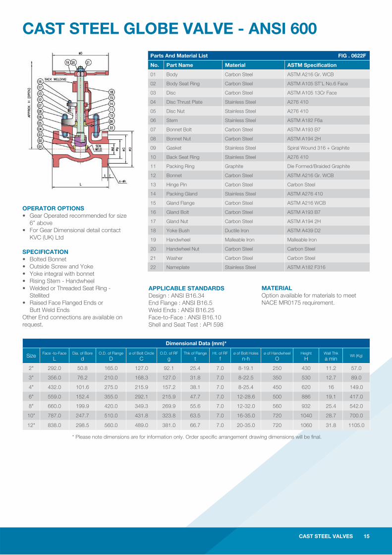
CAST STEEL GLOBE VALVE - ANSI 600Parts And Material List FIG . 0622F
No. Part Name Material ASTM Specification
01 Body Carbon Steel ASTM A216 Gr. WCB
02 Body Seat Ring Carbon Steel ASTM A105 ST’L No.6 Face
03 Disc Carbon Steel ASTM A105 13Cr Face
04 Disc Thrust Plate Stainless Steel A276 410
05 Disc Nut Stainless Steel A276 410
06 Stem Stainless Steel ASTM A182 F6a
07 Bonnet Bolt Carbon Steel ASTM A193 B7
08 Bonnet Nut Carbon Steel ASTM A194 2H
09 Gasket Stainless Steel Spiral Wound 316 + Graphite
10 Back Seat Ring Stainless Steel A276 410
11 Packing Ring Graphite Die Formed/Braided Graphite
12 Bonnet Carbon Steel ASTM A216 Gr. WCB
13 Hinge Pin Carbon Steel Carbon Steel
14 Packing Gland Stainless Steel ASTM A276 410
15 Gland Flange Carbon Steel ASTM A216 WCB
16 Gland Bolt Carbon Steel ASTM A193 B7
17 Gland Nut Carbon Steel ASTM A194 2H
18 Yoke Bush Ductile Iron ASTM A439 D2
19 Handwheel Malleable Iron Malleable Iron
20 Handwheel Nut Carbon Steel Carbon Steel
21 Washer Carbon Steel Carbon Steel
22 Nameplate Stainless Steel ASTM A182 F316
OPERATOR OPTIONS• Gear Operated recommended for size 6” above• For Gear Dimensional detail contact KVC (UK) Ltd
SPECIFICATION• Bolted Bonnet • Outside Screw and Yoke • Yoke integral with bonnet • Rising Stem - Handwheel• Welded or Threaded Seat Ring - Stellited • Raised Face Flanged Ends or Butt Weld EndsOther End connections are available on request.
MATERIALOption available for materials to meet NACE MR0175 requirement.
* Please note dimensions are for information only. Order specifi c arrangement drawing dimensions will be fi nal.
CAST STEEL VALVES 15
Dimensional Data (mm)*
Size Face -to-Face L
Dia. of Bore d
O.D. of Flange D
ø of Bolt Circle C
O.D. of RF g
Thk of Flange t
Ht. of RF f
ø of Bolt Holes n-h
ø of Handwheel O
Height H
Wall Thk a min
Wt (Kg)
2" 292.0 50.8 165.0 127.0 92.1 25.4 7.0 8-19.1 250 430 11.2 57.0
3" 356.0 76.2 210.0 168.3 127.0 31.8 7.0 8-22.5 350 530 12.7 89.0
4" 432.0 101.6 275.0 215.9 157.2 38.1 7.0 8-25.4 450 620 16 149.0
6" 559.0 152.4 355.0 292.1 215.9 47.7 7.0 12-28.6 500 886 19.1 417.0
8" 660.0 199.9 420.0 349.3 269.9 55.6 7.0 12-32.0 560 932 25.4 542.0
10" 787.0 247.7 510.0 431.8 323.8 63.5 7.0 16-35.0 720 1040 28.7 700.0
12" 838.0 298.5 560.0 489.0 381.0 66.7 7.0 20-35.0 720 1060 31.8 1105.0
APPLICABLE STANDARDSDesign : ANSI B16.34 End Flange : ANSI B16.5Weld Ends : ANSI B16.25Face-to-Face : ANSI B16.10Shell and Seat Test : API 598
16 CAST STEEL VALVES
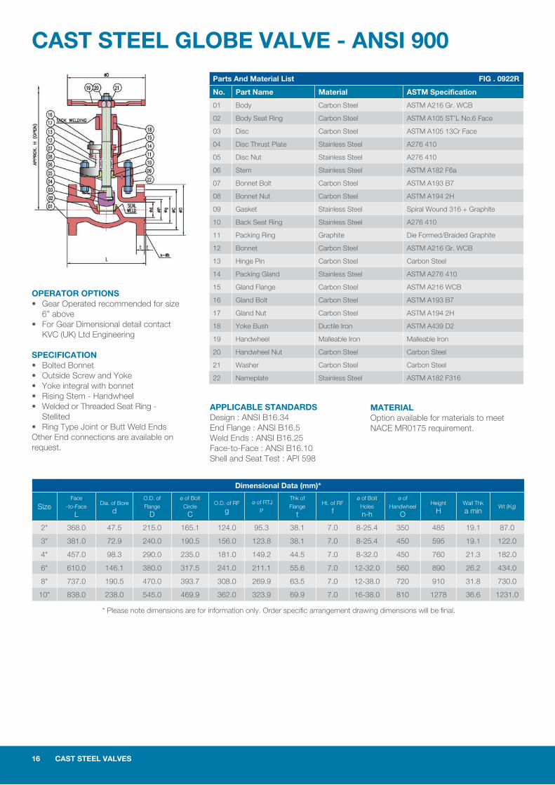
CAST STEEL GLOBE VALVE - ANSI 900Parts And Material List FIG . 0922R
No. Part Name Material ASTM Specification
01 Body Carbon Steel ASTM A216 Gr. WCB
02 Body Seat Ring Carbon Steel ASTM A105 ST’L No.6 Face
03 Disc Carbon Steel ASTM A105 13Cr Face
04 Disc Thrust Plate Stainless Steel A276 410
05 Disc Nut Stainless Steel A276 410
06 Stem Stainless Steel ASTM A182 F6a
07 Bonnet Bolt Carbon Steel ASTM A193 B7
08 Bonnet Nut Carbon Steel ASTM A194 2H
09 Gasket Stainless Steel Spiral Wound 316 + Graphite
10 Back Seat Ring Stainless Steel A276 410
11 Packing Ring Graphite Die Formed/Braided Graphite
12 Bonnet Carbon Steel ASTM A216 Gr. WCB
13 Hinge Pin Carbon Steel Carbon Steel
14 Packing Gland Stainless Steel ASTM A276 410
15 Gland Flange Carbon Steel ASTM A216 WCB
16 Gland Bolt Carbon Steel ASTM A193 B7
17 Gland Nut Carbon Steel ASTM A194 2H
18 Yoke Bush Ductile Iron ASTM A439 D2
19 Handwheel Malleable Iron Malleable Iron
20 Handwheel Nut Carbon Steel Carbon Steel
21 Washer Carbon Steel Carbon Steel
22 Nameplate Stainless Steel ASTM A182 F316
Dimensional Data (mm)*
SizeFace
-to-Face L
Dia. of Bore d
O.D. of
Flange D
ø of Bolt
Circle C
O.D. of RF g
ø of RTJ
P
Thk of
Flange t
Ht. of RF f
ø of Bolt
Holes n-h
ø of
Handwheel O
Height H
Wall Thk a min
Wt (Kg)
2" 368.0 47.5 215.0 165.1 124.0 95.3 38.1 7.0 8-25.4 350 485 19.1 87.0
3" 381.0 72.9 240.0 190.5 156.0 123.8 38.1 7.0 8-25.4 450 595 19.1 122.0
4" 457.0 98.3 290.0 235.0 181.0 149.2 44.5 7.0 8-32.0 450 760 21.3 182.0
6" 610.0 146.1 380.0 317.5 241.0 211.1 55.6 7.0 12-32.0 560 890 26.2 434.0
8" 737.0 190.5 470.0 393.7 308.0 269.9 63.5 7.0 12-38.0 720 910 31.8 730.0
10" 838.0 238.0 545.0 469.9 362.0 323.9 69.9 7.0 16-38.0 810 1278 36.6 1231.0
OPERATOR OPTIONS• Gear Operated recommended for size 6” above• For Gear Dimensional detail contact KVC (UK) Ltd Engineering
SPECIFICATION• Bolted Bonnet • Outside Screw and Yoke • Yoke integral with bonnet • Rising Stem - Handwheel• Welded or Threaded Seat Ring - Stellited • Ring Type Joint or Butt Weld Ends Other End connections are available on request.
MATERIALOption available for materials to meet NACE MR0175 requirement.
* Please note dimensions are for information only. Order specifi c arrangement drawing dimensions will be fi nal.
APPLICABLE STANDARDSDesign : ANSI B16.34 End Flange : ANSI B16.5Weld Ends : ANSI B16.25Face-to-Face : ANSI B16.10Shell and Seat Test : API 598
CAST STEEL VALVES 17
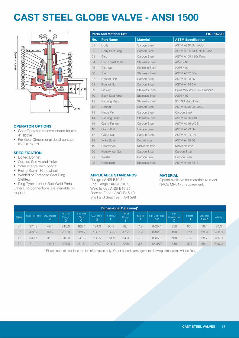
CAST STEEL GLOBE VALVE - ANSI 1500Parts And Material List FIG . 1522R
No. Part Name Material ASTM Specification
01 Body Carbon Steel ASTM A216 Gr. WCB
02 Body Seat Ring Carbon Steel ASTM A105 ST’L No.6 Face
03 Disc Carbon Steel ASTM A105 13Cr Face
04 Disc Thrust Plate Stainless Steel A276 410
05 Disc Nut Stainless Steel A276 410
06 Stem Stainless Steel ASTM A182 F6a
07 Bonnet Bolt Carbon Steel ASTM A193 B7
08 Bonnet Nut Carbon Steel ASTM A194 2H
09 Gasket Stainless Steel Spiral Wound 316 + Graphite
10 Back Seat Ring Stainless Steel A276 410
11 Packing Ring Stainless Steel 316 SS Ring Joint
12 Bonnet Carbon Steel ASTM A216 Gr. WCB
13 Hinge Pin Carbon Steel Carbon Steel
14 Packing Gland Stainless Steel ASTM A276 410
15 Gland Flange Carbon Steel ASTM A216 WCB
16 Gland Bolt Carbon Steel ASTM A193 B7
17 Gland Nut Carbon Steel ASTM A194 2H
18 Yoke Bush Ductile Iron ASTM A439 D2
19 Handwheel Malleable Iron Malleable Iron
20 Handwheel Nut Carbon Steel Carbon Steel
21 Washer Carbon Steel Carbon Steel
22 Nameplate Stainless Steel ASTM A182 F316
OPERATOR OPTIONS• Gear Operated recommended for size 4” above• For Gear Dimensional detail contact KVC (UK) Ltd
SPECIFICATION• Bolted Bonnet • Outside Screw and Yoke • Yoke integral with bonnet • Rising Stem - Handwheel• Welded or Threaded Seat Ring - Stellited • Ring Type Joint or Butt Weld EndsOther End connections are available on request.
MATERIALOption available for materials to meet NACE MR0175 requirement.
* Please note dimensions are for information only. Order specifi c arrangement drawing dimensions will be fi nal.
CAST STEEL VALVES 17
APPLICABLE STANDARDSDesign : ANSI B16.34 End Flange : ANSI B16.5Weld Ends : ANSI B16.25Face-to-Face : ANSI B16.10Shell and Seat Test : API 598
Dimensional Data (mm)*
Size Face -to-Face L
Dia. of Bore d
O.D. of
Flange D
ø of Bolt
Circle C
O.D. of RF g
ø of RTJ P
Thk of
Flange t
Ht. of RF f
ø of Bolt Holes n-h
ø of
Handwheel O
Height H
Wall Thk a min
Wt (Kg)
2" 371.3 49.5 215.0 165.1 124.0 95.3 38.1 7.9 8-25.4 350 650 19.1 87.0
3" 472.9 69.9 265.0 203.2 168.1 136.5 47.7 7.9 8-32.0 450 711 23.9 250.0
4" 549.1 91.9 310.0 241.3 193.5 161.9 54.0 7.9 8-35.0 560 782 28.7 435.0
6" 711.2 136.4 395.0 31.5 247.7 211.1 82.6 9.5 12-38.0 640 927 38.1 540.0
18 CAST STEEL VALVES
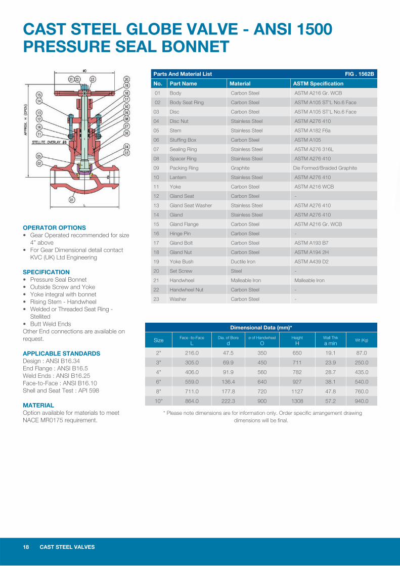
CAST STEEL GLOBE VALVE - ANSI 1500PRESSURE SEAL BONNET
OPERATOR OPTIONS• Gear Operated recommended for size 4” above• For Gear Dimensional detail contact KVC (UK) Ltd Engineering
SPECIFICATION• Pressure Seal Bonnet • Outside Screw and Yoke • Yoke integral with bonnet • Rising Stem - Handwheel• Welded or Threaded Seat Ring - Stellited • Butt Weld EndsOther End connections are available on request.
APPLICABLE STANDARDSDesign : ANSI B16.34End Flange : ANSI B16.5Weld Ends : ANSI B16.25Face-to-Face : ANSI B16.10Shell and Seat Test : API 598
MATERIALOption available for materials to meet NACE MR0175 requirement.
Parts And Material List FIG . 1562B
No. Part Name Material ASTM Specification
01 Body Carbon Steel ASTM A216 Gr. WCB
02 Body Seat Ring Carbon Steel ASTM A105 ST'L No.6 Face
03 Disc Carbon Steel ASTM A105 ST'L No.6 Face
04 Disc Nut Stainless Steel ASTM A276 410
05 Stem Stainless Steel ASTM A182 F6a
06 Stuffing Box Carbon Steel ASTM A105
07 Sealing Ring Stainless Steel ASTM A276 316L
08 Spacer Ring Stainless Steel ASTM A276 410
09 Packing Ring Graphite Die Formed/Braided Graphite
10 Lantern Stainless Steel ASTM A276 410
11 Yoke Carbon Steel ASTM A216 WCB
12 Gland Seat Carbon Steel -
13 Gland Seat Washer Stainless Steel ASTM A276 410
14 Gland Stainless Steel ASTM A276 410
15 Gland Flange Carbon Steel ASTM A216 Gr. WCB
16 Hinge Pin Carbon Steel -
17 Gland Bolt Carbon Steel ASTM A193 B7
18 Gland Nut Carbon Steel ASTM A194 2H
19 Yoke Bush Ductile Iron ASTM A439 D2
20 Set Screw Steel -
21 Handwheel Malleable Iron Malleable Iron
22 Handwheel Nut Carbon Steel -
23 Washer Carbon Steel -
Dimensional Data (mm)*
Size Face -to-Face L
Dia. of Bore d
ø of Handwheel O
Height H
Wall Thk a min
Wt (Kg)
2" 216.0 47.5 350 650 19.1 87.0
3" 305.0 69.9 450 711 23.9 250.0
4" 406.0 91.9 560 782 28.7 435.0
6" 559.0 136.4 640 927 38.1 540.0
8" 711.0 177.8 720 1127 47.8 760.0
10" 864.0 222.3 900 1308 57.2 940.0
* Please note dimensions are for information only. Order specifi c arrangement drawing dimensions will be fi nal.
CAST STEEL VALVES 19
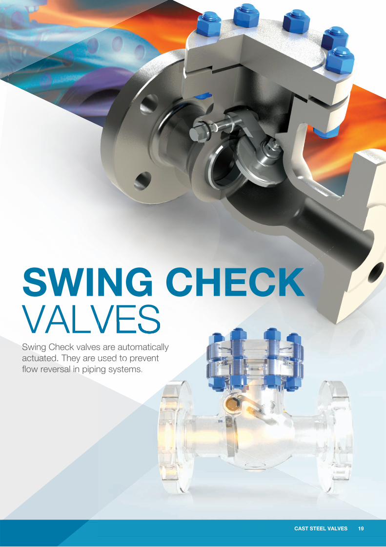
SWING CHECK VALVESSwing Check valves are automatically actuated. They are used to prevent fl ow reversal in piping systems.
CAST STEEL VALVES 19
s are automatically used to preused to prevent ng systems.
20 CAST STEEL VALVES
CAST STEEL SWING CHECK VALVES
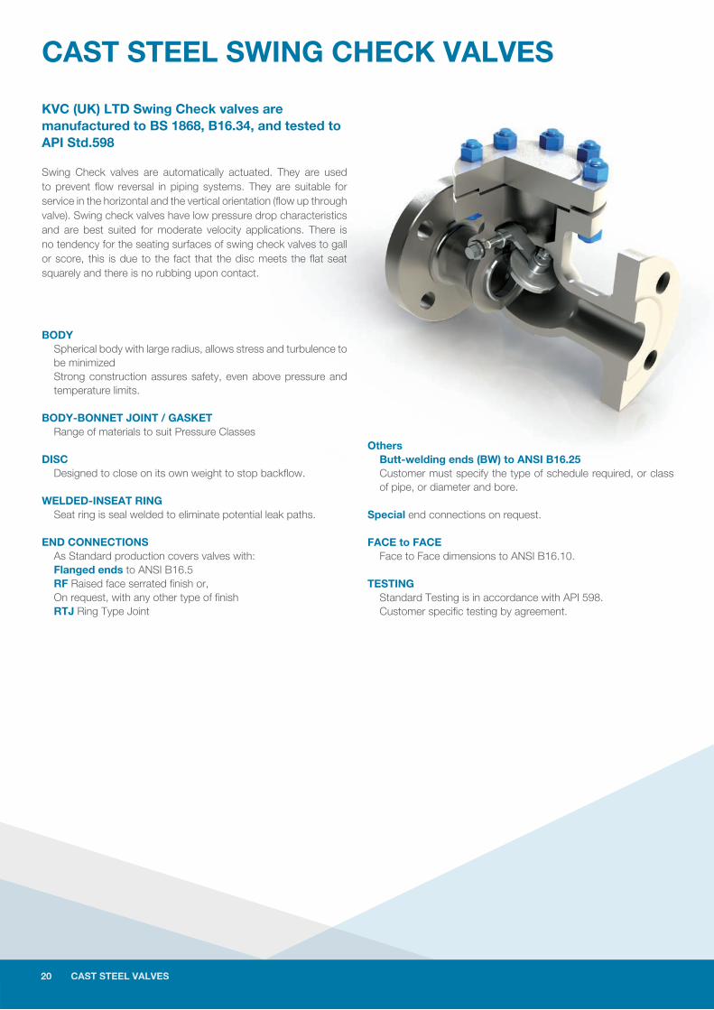
KVC (UK) LTD Swing Check valves are manufactured to BS 1868, B16.34, and tested to API Std.598
Swing Check valves are automatically actuated. They are used to prevent fl ow reversal in piping systems. They are suitable for service in the horizontal and the vertical orientation (fl ow up through valve). Swing check valves have low pressure drop characteristics and are best suited for moderate velocity applications. There is no tendency for the seating surfaces of swing check valves to gall or score, this is due to the fact that the disc meets the fl at seat squarely and there is no rubbing upon contact.
BODY Spherical body with large radius, allows stress and turbulence to be minimized Strong construction assures safety, even above pressure and temperature limits.
BODY-BONNET JOINT / GASKET Range of materials to suit Pressure Classes
DISC Designed to close on its own weight to stop backfl ow.
WELDED-INSEAT RING Seat ring is seal welded to eliminate potential leak paths.
END CONNECTIONS As Standard production covers valves with: Flanged ends to ANSI B16.5 RF Raised face serrated fi nish or, On request, with any other type of fi nish RTJ Ring Type Joint
Others Butt-welding ends (BW) to ANSI B16.25 Customer must specify the type of schedule required, or class of pipe, or diameter and bore. Special end connections on request.
FACE to FACE Face to Face dimensions to ANSI B16.10.
TESTING Standard Testing is in accordance with API 598. Customer specifi c testing by agreement.
20 CAST STEEL VALVES

CAST STEEL VALVES 21
CAST STEEL SWING CHECK VALVE - ANSI 150
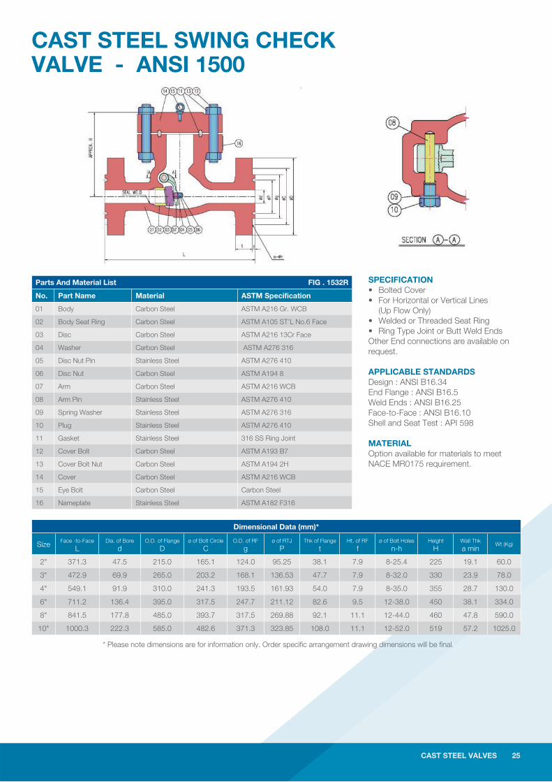
SPECIFICATION • Bolted Cover • For Horizontal or Vertical Lines (Up Flow Only)• Welded or Threaded Seat Ring • Raised Face Flanged Ends or Butt Weld Ends Other End connections are available on request.
APPLICABLE STANDARDS Design : ANSI B16.34End Flange : ANSI B16.5Weld Ends : ANSI B16.25Face-to-Face : ANSI B16.10Shell and Seat Test : API 598
MATERIAL Option available for materials to meet NACE MR0175 requirement.
Parts And Material List FIG . 0132F
No. Part Name Material ASTM Specification
01 Body Carbon Steel ASTM A216 Gr. WCB
02 Body Seat Ring Carbon Steel ASTM A105 ST’L No.6 Face
03 Disc Carbon Steel ASTM A216 13Cr Face
04 Washer Carbon Steel ASTM A276 316
05 Disc Nut Pin Stainless Steel ASTM A276 410
06 Disc Nut Carbon Steel ASTM A194 8
07 Arm Carbon Steel ASTM A216 WCB
08 Arm Pin Stainless Steel ASTM A276 410
09 Spring Washer Stainless Steel ASTM A276 316
10 Plug Stainless Steel ASTM A276 410
11 Gasket Stainless Steel Spiral Wound 316+Graphite
12 Cover Bolt Carbon Steel ASTM A193 B7
13 Cover Bolt Nut Carbon Steel ASTM A194 2H
14 Cover Carbon Steel ASTM A216 WCB
15 Eye Bolt Carbon Steel Carbon Steel
16 Nameplate Stainless Steel ASTM A182 F316
CAST STEEL VALVES 21
Dimensional Data (mm)*
Size Face -to-Face L
Dia. of Bore d
O.D. of Flange D
ø of Bolt Circle C
O.D. of RF g
Thk of Flange t
Ht. of RF f
ø of Bolt Holes h
Height H
Wall Thk a min
Wt (Kg)
2” 203.0 50.8 150.0 120.7 92.1 16.3 2.0 4-19.1 165 8.6 18.0
3” 241.0 76.2 190.0 152.4 127.0 19.5 2.0 4-19.1 186 10.4 29.0
4” 292.0 101.6 230.0 190.5 157.2 24.3 2.0 8-19.1 217 11.2 48.0
6” 356.0 152.4 280.0 241.3 215.9 25.9 2.0 8-22.4 266 11.9 77.0
8” 495.0 203.2 345.0 298.5 269.9 29.0 2.0 8-22.4 318 12.7 133.0
10” 622.0 254.0 405.0 362.0 323.8 30.6 2.0 12-25.4 368 14.2 266.0
12” 698.0 304.8 485.0 431.8 381.0 32.2 2.0 12-25.4 406 16.0 347.0
14” 787.0 336.6 535.0 476.3 412.8 35.4 2.0 12-28.6 432 16.8 451.0
16” 864.0 387.4 595.0 539.8 469.9 37.0 2.0 16-28.6 483 17.5 556.0
18” 978.0 438.2 635.0 577.9 533.4 40.1 2.0 16-32.0 600 18.3 784.0
20” 978.0 489.0 700.0 635.0 584.2 43.3 2.0 20-32.0 660 19.1 835.0
24” 1295.0 590.6 815.0 749.3 692.2 48.1 2.0 20-35.0 740 20.6 1150.0
* Please note dimensions are for information only. Order specifi c arrangement drawing dimensions will be fi nal.
22 CAST STEEL VALVES
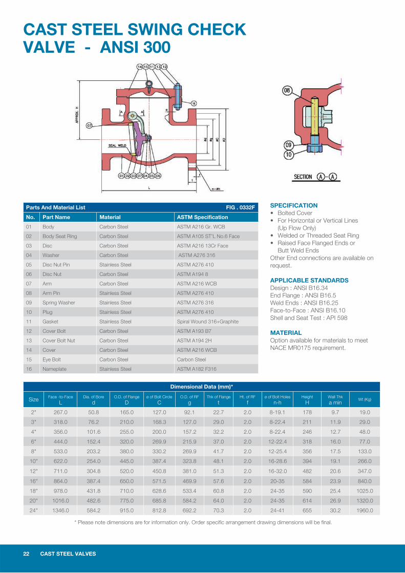
CAST STEEL SWING CHECK VALVE - ANSI 300
SPECIFICATION • Bolted Cover • For Horizontal or Vertical Lines (Up Flow Only)• Welded or Threaded Seat Ring • Raised Face Flanged Ends or Butt Weld Ends Other End connections are available on request.
APPLICABLE STANDARDS Design : ANSI B16.34End Flange : ANSI B16.5Weld Ends : ANSI B16.25Face-to-Face : ANSI B16.10Shell and Seat Test : API 598
MATERIAL Option available for materials to meet NACE MR0175 requirement.
Parts And Material List FIG . 0332F
No. Part Name Material ASTM Specification
01 Body Carbon Steel ASTM A216 Gr. WCB
02 Body Seat Ring Carbon Steel ASTM A105 ST’L No.6 Face
03 Disc Carbon Steel ASTM A216 13Cr Face
04 Washer Carbon Steel ASTM A276 316
05 Disc Nut Pin Stainless Steel ASTM A276 410
06 Disc Nut Carbon Steel ASTM A194 8
07 Arm Carbon Steel ASTM A216 WCB
08 Arm Pin Stainless Steel ASTM A276 410
09 Spring Washer Stainless Steel ASTM A276 316
10 Plug Stainless Steel ASTM A276 410
11 Gasket Stainless Steel Spiral Wound 316+Graphite
12 Cover Bolt Carbon Steel ASTM A193 B7
13 Cover Bolt Nut Carbon Steel ASTM A194 2H
14 Cover Carbon Steel ASTM A216 WCB
15 Eye Bolt Carbon Steel Carbon Steel
16 Nameplate Stainless Steel ASTM A182 F316
Dimensional Data (mm)*
Size Face -to-Face L
Dia. of Bore d
O.D. of Flange D
ø of Bolt Circle C
O.D. of RF g
Thk of Flange t
Ht. of RF f
ø of Bolt Holes n-h
Height H
Wall Thk a min
Wt (Kg)
2" 267.0 50.8 165.0 127.0 92.1 22.7 2.0 8-19.1 178 9.7 19.0
3" 318.0 76.2 210.0 168.3 127.0 29.0 2.0 8-22.4 211 11.9 29.0
4" 356.0 101.6 255.0 200.0 157.2 32.2 2.0 8-22.4 246 12.7 48.0
6" 444.0 152.4 320.0 269.9 215.9 37.0 2.0 12-22.4 318 16.0 77.0
8" 533.0 203.2 380.0 330.2 269.9 41.7 2.0 12-25.4 356 17.5 133.0
10" 622.0 254.0 445.0 387.4 323.8 48.1 2.0 16-28.6 394 19.1 266.0
12" 711.0 304.8 520.0 450.8 381.0 51.3 2.0 16-32.0 482 20.6 347.0
16" 864.0 387.4 650.0 571.5 469.9 57.6 2.0 20-35 584 23.9 840.0
18" 978.0 431.8 710.0 628.6 533.4 60.8 2.0 24-35 590 25.4 1025.0
20" 1016.0 482.6 775.0 685.8 584.2 64.0 2.0 24-35 614 26.9 1320.0
24" 1346.0 584.2 915.0 812.8 692.2 70.3 2.0 24-41 655 30.2 1960.0
* Please note dimensions are for information only. Order specifi c arrangement drawing dimensions will be fi nal.
CAST STEEL VALVES 23
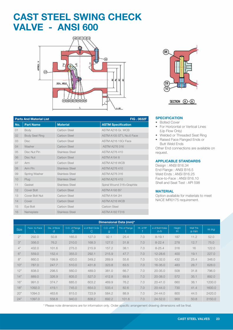
CAST STEEL SWING CHECK VALVE - ANSI 600
SPECIFICATION • Bolted Cover • For Horizontal or Vertical Lines (Up Flow Only)• Welded or Threaded Seat Ring • Raised Face Flanged Ends or Butt Weld Ends Other End connections are available on request.
APPLICABLE STANDARDS Design : ANSI B16.34End Flange : ANSI B16.5Weld Ends : ANSI B16.25Face-to-Face : ANSI B16.10Shell and Seat Test : API 598
MATERIAL Option available for materials to meet NACE MR0175 requirement.
Parts And Material List FIG . 0632F
No. Part Name Material ASTM Specification
01 Body Carbon Steel ASTM A216 Gr. WCB
02 Body Seat Ring Carbon Steel ASTM A105 ST’L No.6 Face
03 Disc Carbon Steel ASTM A216 13Cr Face
04 Washer Carbon Steel ASTM A276 316
05 Disc Nut Pin Stainless Steel ASTM A276 410
06 Disc Nut Carbon Steel ASTM A194 8
07 Arm Carbon Steel ASTM A216 WCB
08 Arm Pin Stainless Steel ASTM A276 410
09 Spring Washer Stainless Steel ASTM A276 316
10 Plug Stainless Steel ASTM A276 410
11 Gasket Stainless Steel Spiral Wound 316+Graphite
12 Cover Bolt Carbon Steel ASTM A193 B7
13 Cover Bolt Nut Carbon Steel ASTM A194 2H
14 Cover Carbon Steel ASTM A216 WCB
15 Eye Bolt Carbon Steel Carbon Steel
16 Nameplate Stainless Steel ASTM A182 F316
CAST STEEL VALVES 23
Parts And Material List FIG . 0632F
No. Part Name Material ASTM Specification
01 Body Carbon Steel ASTM A216 Gr. WCB
02 Body Seat Ring Carbon Steel ASTM A105 ST’L No.6 Face
03 Disc Carbon Steel ASTM A216 13Cr Face
04 Washer Carbon Steel ASTM A276 316
05 Disc Nut Pin Stainless Steel ASTM A276 410
06 Disc Nut Carbon Steel ASTM A194 8
07 Arm Carbon Steel ASTM A216 WCB
08 Arm Pin Stainless Steel ASTM A276 410
09 Spring Washer Stainless Steel ASTM A276 316
10 Plug Stainless Steel ASTM A276 410
11 Gasket Stainless Steel Spiral Wound 316+Graphite
12 Cover Bolt Carbon Steel ASTM A193 B7
13 Cover Bolt Nut Carbon Steel ASTM A194 2H
14 Cover Carbon Steel ASTM A216 WCB
15 Eye Bolt Carbon Steel Carbon Steel
16 Nameplate Stainless Steel ASTM A182 F316
* Please note dimensions are for information only. Order specifi c arrangement drawing dimensions will be fi nal.
Dimensional Data (mm)*
Size Face -to-Face L
Dia. of Bore d
O.D. of Flange D
ø of Bolt Circle C
O.D. of RF g
Thk of Flange t
Ht. of RF f
ø of Bolt Holes n-h
Height H
Wall Thk a min
Wt (Kg)
2” 292.0 50.8 165.0 127.0 92.1 25.4 7.0 8-19.1 187 11.2 52.0
3” 356.0 76.2 210.0 168.3 127.0 31.8 7.0 8-22.4 278 12.7 75.0
4” 432.0 101.6 275.0 215.9 157.2 38.1 7.0 8-25.4 316 16 122.0
6” 559.0 152.4 355.0 292.1 215.9 47.7 7.0 12-28.6 400 19.1 227.0
8” 660.0 199.9 420.0 349.2 269.9 55.6 7.0 12-32.0 432 25.4 346.0
10” 787.0 247.7 510.0 431.8 323.8 63.5 7.0 16-35.0 483 28.7 628.0
12” 838.0 298.5 560.0 489.0 381.0 66.7 7.0 20-35.0 508 31.8 796.0
14” 889.0 326.9 605.0 527.0 412.8 69.9 7.0 20-38.0 572 35.1 892.0
16” 991.0 374.7 685.0 603.2 469.9 76.2 7.0 20-41.0 660 38.1 1200.0
18” 1092.0 419.1 745.0 654.0 533.4 82.6 7.0 20-44.0 730 41.4 1600.0
20” 1094.0 463.6 815.0 723.9 584.2 88.9 7.0 24-44.0 800 44.5 2420.0
24” 1397.0 558.8 940.0 838.2 692.2 101.6 7.0 24-52.0 900 50.8 3150.0
24 CAST STEEL VALVES
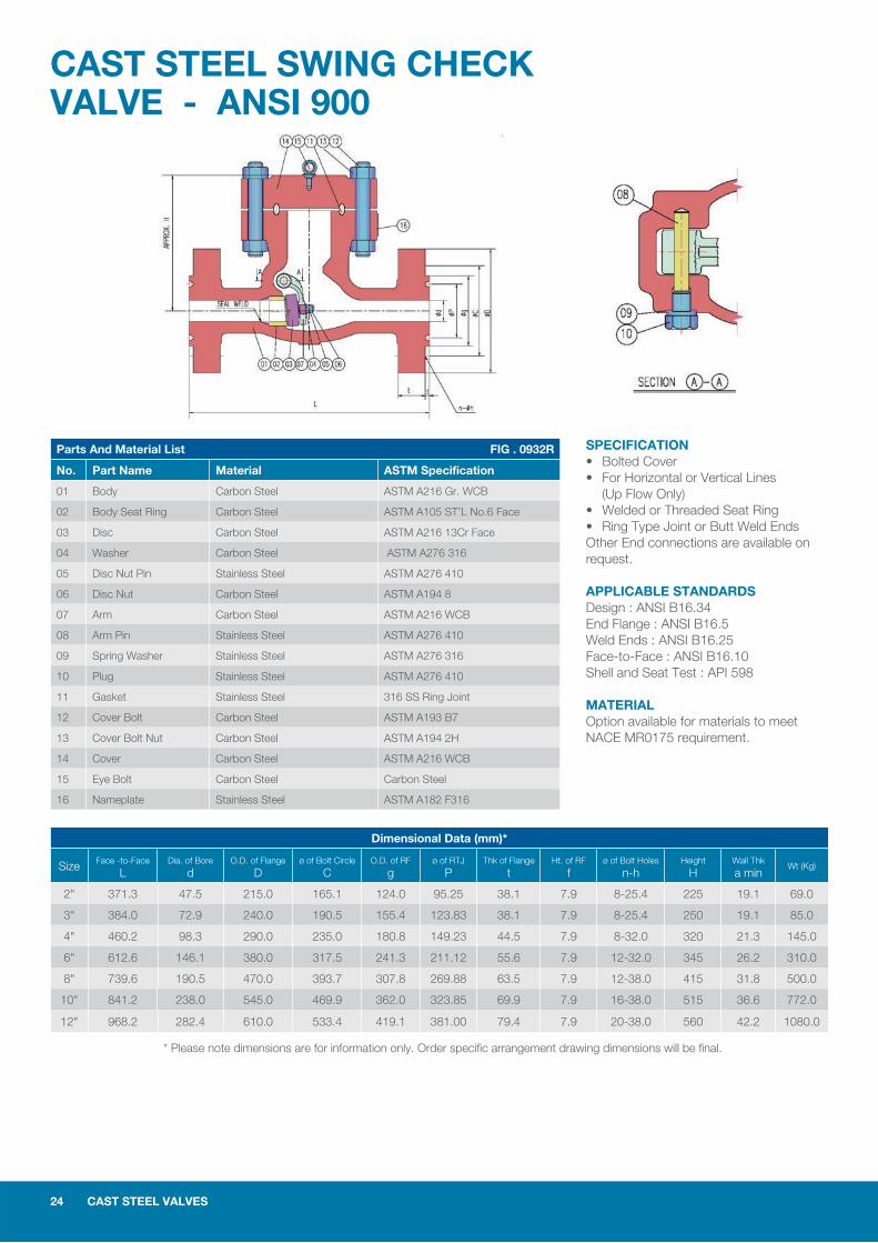
CAST STEEL SWING CHECK VALVE - ANSI 900
SPECIFICATION • Bolted Cover • For Horizontal or Vertical Lines (Up Flow Only)• Welded or Threaded Seat Ring • Ring Type Joint or Butt Weld Ends Other End connections are available on request.
APPLICABLE STANDARDS Design : ANSI B16.34End Flange : ANSI B16.5Weld Ends : ANSI B16.25Face-to-Face : ANSI B16.10Shell and Seat Test : API 598
MATERIAL Option available for materials to meet NACE MR0175 requirement.
Parts And Material List FIG . 0932R
No. Part Name Material ASTM Specification
01 Body Carbon Steel ASTM A216 Gr. WCB
02 Body Seat Ring Carbon Steel ASTM A105 ST’L No.6 Face
03 Disc Carbon Steel ASTM A216 13Cr Face
04 Washer Carbon Steel ASTM A276 316
05 Disc Nut Pin Stainless Steel ASTM A276 410
06 Disc Nut Carbon Steel ASTM A194 8
07 Arm Carbon Steel ASTM A216 WCB
08 Arm Pin Stainless Steel ASTM A276 410
09 Spring Washer Stainless Steel ASTM A276 316
10 Plug Stainless Steel ASTM A276 410
11 Gasket Stainless Steel 316 SS Ring Joint
12 Cover Bolt Carbon Steel ASTM A193 B7
13 Cover Bolt Nut Carbon Steel ASTM A194 2H
14 Cover Carbon Steel ASTM A216 WCB
15 Eye Bolt Carbon Steel Carbon Steel
16 Nameplate Stainless Steel ASTM A182 F316
Dimensional Data (mm)*
Size Face -to-Face L
Dia. of Bore d
O.D. of Flange D
ø of Bolt Circle C
O.D. of RF g
ø of RTJ P
Thk of Flange t
Ht. of RF f
ø of Bolt Holes n-h
Height H
Wall Thk a min
Wt (Kg)
2" 371.3 47.5 215.0 165.1 124.0 95.25 38.1 7.9 8-25.4 225 19.1 69.0
3" 384.0 72.9 240.0 190.5 155.4 123.83 38.1 7.9 8-25.4 250 19.1 85.0
4" 460.2 98.3 290.0 235.0 180.8 149.23 44.5 7.9 8-32.0 320 21.3 145.0
6" 612.6 146.1 380.0 317.5 241.3 211.12 55.6 7.9 12-32.0 345 26.2 310.0
8" 739.6 190.5 470.0 393.7 307.8 269.88 63.5 7.9 12-38.0 415 31.8 500.0
10" 841.2 238.0 545.0 469.9 362.0 323.85 69.9 7.9 16-38.0 515 36.6 772.0
12" 968.2 282.4 610.0 533.4 419.1 381.00 79.4 7.9 20-38.0 560 42.2 1080.0
* Please note dimensions are for information only. Order specifi c arrangement drawing dimensions will be fi nal.
CAST STEEL VALVES 25
CAST STEEL SWING CHECK VALVE - ANSI 1500
SPECIFICATION • Bolted Cover • For Horizontal or Vertical Lines (Up Flow Only)• Welded or Threaded Seat Ring • Ring Type Joint or Butt Weld EndsOther End connections are available on request.
APPLICABLE STANDARDS Design : ANSI B16.34End Flange : ANSI B16.5Weld Ends : ANSI B16.25Face-to-Face : ANSI B16.10Shell and Seat Test : API 598
MATERIAL Option available for materials to meet NACE MR0175 requirement.
Parts And Material List FIG . 1532R
No. Part Name Material ASTM Specification
01 Body Carbon Steel ASTM A216 Gr. WCB
02 Body Seat Ring Carbon Steel ASTM A105 ST’L No.6 Face
03 Disc Carbon Steel ASTM A216 13Cr Face
04 Washer Carbon Steel ASTM A276 316
05 Disc Nut Pin Stainless Steel ASTM A276 410
06 Disc Nut Carbon Steel ASTM A194 8
07 Arm Carbon Steel ASTM A216 WCB
08 Arm Pin Stainless Steel ASTM A276 410
09 Spring Washer Stainless Steel ASTM A276 316
10 Plug Stainless Steel ASTM A276 410
11 Gasket Stainless Steel 316 SS Ring Joint
12 Cover Bolt Carbon Steel ASTM A193 B7
13 Cover Bolt Nut Carbon Steel ASTM A194 2H
14 Cover Carbon Steel ASTM A216 WCB
15 Eye Bolt Carbon Steel Carbon Steel
16 Nameplate Stainless Steel ASTM A182 F316
* Please note dimensions are for information only. Order specifi c arrangement drawing dimensions will be fi nal.g dimensions will be fi nal.
CAST STEEL VALVES 25
Dimensional Data (mm)*
Size Face -to-Face L
Dia. of Bore d
O.D. of Flange D
ø of Bolt Circle C
O.D. of RF g
ø of RTJ P
Thk of Flange t
Ht. of RF f
ø of Bolt Holes n-h
Height H
Wall Thk a min
Wt (Kg)
2" 371.3 47.5 215.0 165.1 124.0 95.25 38.1 7.9 8-25.4 225 19.1 60.0
3" 472.9 69.9 265.0 203.2 168.1 136.53 47.7 7.9 8-32.0 330 23.9 78.0
4" 549.1 91.9 310.0 241.3 193.5 161.93 54.0 7.9 8-35.0 355 28.7 130.0
6" 711.2 136.4 395.0 317.5 247.7 211.12 82.6 9.5 12-38.0 450 38.1 334.0
8" 841.5 177.8 485.0 393.7 317.5 269.88 92.1 11.1 12-44.0 460 47.8 590.0
10" 1000.3 222.3 585.0 482.6 371.3 323.85 108.0 11.1 12-52.0 519 57.2 1025.0

26 CAST STEEL VALVES
CAST STEEL SWING CHECK VALVE - ANSI 1500PRESSURE SEAL BONNET
SPECIFICATION • Bolted Cover • For Horizontal or Vertical Lines (Up Flow Only)• Welded or Threaded Seat Ring • Butt Weld Ends Other End connections are available on request.
APPLICABLE STANDARDS Design : ANSI B16.34End Flange : ANSI B16.5Weld Ends : ANSI B16.25Face-to-Face : ANSI B16.10Shell and Seat Test : API 598
MATERIAL Option available for materials to meet NACE MR0175 requirement.
Parts And Material List FIG . 1572B
No. Part Name Material ASTM Specification
01 Body Carbon Steel ASTM A216 Gr. WCB
02 Body Seat Ring Carbon Steel ASTM A105 ST'L No.6 Face
03 Disc Carbon Steel ASTM A105 ST'L No.6 Face
04 Washer Stainless Steel ASTM A276 316
05 Disc Nut Screw Stainless Steel ASTM A276 410
06 Disc Nut Carbon Steel ASTM A194 8
07 Hinge Carbon Steel ASTM A216 WCB
08 Pin Stainless Steel ASTM A276 410
09 Packing Graphite Graphite
10 Hinge pin Stainless Steel ASTM A276 410
11 Plug Stainless Steel ASTM A276 410
12 Plug Bolt Carbon Steel ASTM A193 B7
13 Plug bolt Nut Carbon Steel ASTM A194 2H
14 Cover Carbon Steel ASTM A105
15 Sealing Ring Stainless Steel ASTM A276 316L
16 Pressure Ring Stainless Steel ASTM A276 410
17 Segment Ring Stainless Steel ASTM A276 410
18 Cover Clamp Carbon Steel ASTM A105
19 Cover Bolt Carbon Steel ASTM A193 B7
20 Cover Bolt Nut Carbon Steel ASTM A194 2H
21 Eye Bolt Carbon Steel Carbon Steel
Dimensional Data (mm)*
Size Face -to-Face L
Dia. of Bore d
Height H
Wall Thk a min
Wt (Kg)
3" 305.0 69.9 330.0 23.9 78.0
4" 406.0 91.9 355.0 28.7 130.0
6" 559.0 136.4 400.0 38.1 334.0
8" 711.0 177.8 460.0 47.8 590.0
10" 864.0 222.3 630.0 57.2 1025.0
* Please note dimensions are for information only. Order specifi c arrangement drawing dimensions will be fi nal.
CAST STEEL VALVES 27
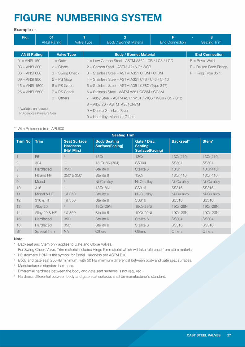
FIGURE NUMBERING SYSTEMExample : -
Fig. 01ANSI Rating
1Valve Type
2Body / Bonnet Materia
F - 8End Connection Seating Trim
ANSI Rating Valve Type Body / Bonnet Material End Connection
01= ANSI 150 1 = Gate 1 = Low Carbon Steel - ASTM A352 LCB / LC3 / LCC B = Bevel Weld
03 = ANSI 300 2 = Globe 2 = Carbon Steel - ASTM A216 Gr.WCB F = Raised Face Flange
06 = ANSI 600 3 = Swing Check 3 = Stainless Steel - ASTM A351 CF8M / CF3M R = Ring Type Joint
09 = ANSI 900 5 = PS Gate 4 = Stainless Steel - ASTM A351 CF8 / CF3 / CF10
15 = ANSI 1500 6 = PS Globe 5 = Stainless Steel - ASTM A351 CF8C (Type 347)
25 = ANSI 2500* 7 = PS Check 6 = Stainess Steel - ASTM A351 CG8M / CG3M
0 = Others 7 = Alloy Steel - ASTM A217 WC1 / WC6 / WC9 / C5 / C12
* Available on request PS denotes Pressure Seal
8 = Alloy 20 - ASTM A351CN7M
9 = Duplex Stainless Steel
0 = Hastelloy, Monel or Others
** With Reference from API 600
Note:* Backseat and Stem only applies to Gate and Globe Valves. For Swing Check Valve, Trim material includes Hinge Pin material which will take reference from stem material.a HB (formerly HBN) is the symbol for Brinell Hardness per ASTM E10.b Body and gate seat 250HB minimum, with 50 HB minimum differential between body and gate seat surfaces.c Manufacturer’s standard hardness.d Differential hardness between the body and gate seat surfaces is not required.f Hardness differential between body and gate seat surfaces shall be manufacturer’s standard.
CAST STEEL VALVES 27
Seating Trim
Trim No Trim Seat Surface Hardness (Hba Min.)
Body Seating Surface(Facing)
Gate / Disc Seating Surface(Facing)
Backseat* Stem*
1 F6 b 13Cr 13Cr 13Cr(410) 13Cr(410)
2 304 c 18 Cr-8Ni(304) SS304 SS304 SS304
5 Hardfaced 350d Stellite 6 Stellite 6 13Cr 13Cr(410)
8 F6 and HF 250f & 350f Stellite 6 13Cr 13Cr(410) 13Cr(410)
9 Monel c Ni-Cu alloy Ni-Cu alloy Ni-Cu alloy Ni-Cu alloy
10 316 c 18Cr-8Ni SS316 SS316 SS316
11 Monel & HF c & 350f Stellite 6 Ni-Cu alloy Ni-Cu alloy Ni-Cu alloy
12 316 & HF c & 350f Stellite 6 SS316 SS316 SS316
13 Alloy 20 c 19Cr-29Ni 19Cr-29Ni 19Cr-29Ni 19Cr-29Ni
14 Alloy 20 & HF c & 350f Stellite 6 19Cr-29Ni 19Cr-29Ni 19Cr-29Ni
15 Hardfaced 350d Stellite 6 Stellite 6 SS304 SS304
16 Hardfaced 350d Stellite 6 Stellite 6 SS316 SS316
ST Special Trim NA Others Others Others Others
28 CAST STEEL VALVES
ENGINEERING DATA
CAST STEEL VALVES 29
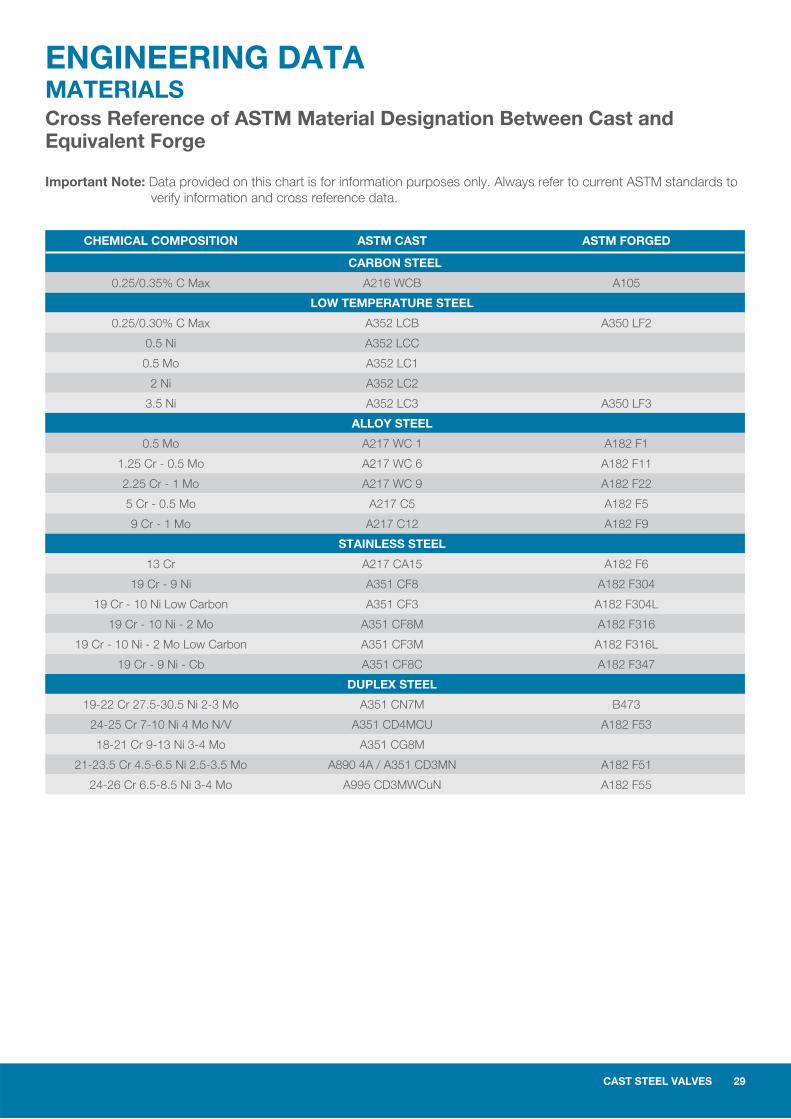
ENGINEERING DATAMATERIALSCross Reference of ASTM Material Designation Between Cast and Equivalent Forge
Important Note: Data provided on this chart is for information purposes only. Always refer to current ASTM standards to verify information and cross reference data.
CHEMICAL COMPOSITION ASTM CAST ASTM FORGED
CARBON STEEL
0.25/0.35% C Max A216 WCB A105
LOW TEMPERATURE STEEL
0.25/0.30% C Max A352 LCB A350 LF2
0.5 Ni A352 LCC
0.5 Mo A352 LC1
2 Ni A352 LC2
3.5 Ni A352 LC3 A350 LF3
ALLOY STEEL
0.5 Mo A217 WC 1 A182 F1
1.25 Cr - 0.5 Mo A217 WC 6 A182 F11
2.25 Cr - 1 Mo A217 WC 9 A182 F22
5 Cr - 0.5 Mo A217 C5 A182 F5
9 Cr - 1 Mo A217 C12 A182 F9
STAINLESS STEEL
13 Cr A217 CA15 A182 F6
19 Cr - 9 Ni A351 CF8 A182 F304
19 Cr - 10 Ni Low Carbon A351 CF3 A182 F304L
19 Cr - 10 Ni - 2 Mo A351 CF8M A182 F316
19 Cr - 10 Ni - 2 Mo Low Carbon A351 CF3M A182 F316L
19 Cr - 9 Ni - Cb A351 CF8C A182 F347
DUPLEX STEEL
19-22 Cr 27.5-30.5 Ni 2-3 Mo A351 CN7M B473
24-25 Cr 7-10 Ni 4 Mo N/V A351 CD4MCU A182 F53
18-21 Cr 9-13 Ni 3-4 Mo A351 CG8M
21-23.5 Cr 4.5-6.5 Ni 2.5-3.5 Mo A890 4A / A351 CD3MN A182 F51
24-26 Cr 6.5-8.5 Ni 3-4 Mo A995 CD3MWCuN A182 F55
30 CAST STEEL VALVES
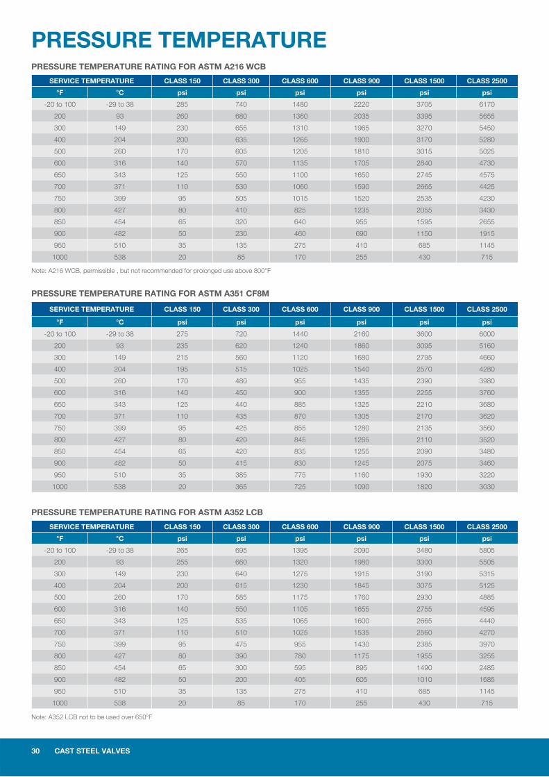
PRESSURE TEMPERATURE
SERVICE TEMPERATURE CLASS 150 CLASS 300 CLASS 600 CLASS 900 CLASS 1500 CLASS 2500
°F °C psi psi psi psi psi psi
-20 to 100 -29 to 38 285 740 1480 2220 3705 6170
200 93 260 680 1360 2035 3395 5655
300 149 230 655 1310 1965 3270 5450
400 204 200 635 1265 1900 3170 5280
500 260 170 605 1205 1810 3015 5025
600 316 140 570 1135 1705 2840 4730
650 343 125 550 1100 1650 2745 4575
700 371 110 530 1060 1590 2665 4425
750 399 95 505 1015 1520 2535 4230
800 427 80 410 825 1235 2055 3430
850 454 65 320 640 955 1595 2655
900 482 50 230 460 690 1150 1915
950 510 35 135 275 410 685 1145
1000 538 20 85 170 255 430 715
SERVICE TEMPERATURE CLASS 150 CLASS 300 CLASS 600 CLASS 900 CLASS 1500 CLASS 2500
°F °C psi psi psi psi psi psi
-20 to 100 -29 to 38 275 720 1440 2160 3600 6000
200 93 235 620 1240 1860 3095 5160
300 149 215 560 1120 1680 2795 4660
400 204 195 515 1025 1540 2570 4280
500 260 170 480 955 1435 2390 3980
600 316 140 450 900 1355 2255 3760
650 343 125 440 885 1325 2210 3680
700 371 110 435 870 1305 2170 3620
750 399 95 425 855 1280 2135 3560
800 427 80 420 845 1265 2110 3520
850 454 65 420 835 1255 2090 3480
900 482 50 415 830 1245 2075 3460
950 510 35 385 775 1160 1930 3220
1000 538 20 365 725 1090 1820 3030
SERVICE TEMPERATURE CLASS 150 CLASS 300 CLASS 600 CLASS 900 CLASS 1500 CLASS 2500
°F °C psi psi psi psi psi psi
-20 to 100 -29 to 38 265 695 1395 2090 3480 5805
200 93 255 660 1320 1980 3300 5505
300 149 230 640 1275 1915 3190 5315
400 204 200 615 1230 1845 3075 5125
500 260 170 585 1175 1760 2930 4885
600 316 140 550 1105 1655 2755 4595
650 343 125 535 1065 1600 2665 4440
700 371 110 510 1025 1535 2560 4270
750 399 95 475 955 1430 2385 3970
800 427 80 390 780 1175 1955 3255
850 454 65 300 595 895 1490 2485
900 482 50 200 405 605 1010 1685
950 510 35 135 275 410 685 1145
1000 538 20 85 170 255 430 715
PRESSURE TEMPERATURE RATING FOR ASTM A216 WCB
Note: A216 WCB, permissible , but not recommended for prolonged use above 800°F
Note: A352 LCB not to be used over 650°F
PRESSURE TEMPERATURE RATING FOR ASTM A351 CF8M
PRESSURE TEMPERATURE RATING FOR ASTM A352 LCB
CAST STEEL VALVES 31
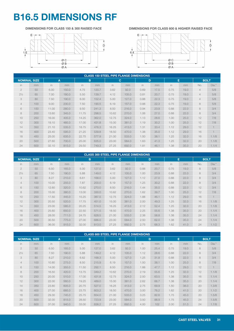
B16.5 DIMENSIONS RF
CLASS 150 STEEL PIPE FLANGE DIMENSIONS
NOMINAL SIZE A B C D E BOLT
in mm in mm in mm in mm in mm in mm No. Dia."
2 50 6.00 150.0 4.75 120.7 3.62 92.0 0.69 17.5 0.75 19.0 4 5/8
2½ 65 7.00 180.0 5.50 139.7 4.12 105.0 0.81 20.7 0.75 19.0 4 5/8
3 80 7.50 190.0 6.00 152.4 5.00 127.0 0.88 22.3 0.75 19.0 4 5/8
4 100 9.00 230.0 7.50 190.5 6.19 157.0 0.88 22.3 0.75 19.0 8 5/8
6 150 11.00 280.0 9.50 241.3 8.50 216.0 0.94 23.9 0.88 22.0 8 3/4
8 200 13.60 345.0 11.75 298.5 10.62 270.0 1.06 27.0 0.88 22.0 8 3/4
10 250 16.00 405.0 14.25 362.0 12.75 324.0 1.13 28.6 1.00 25.0 12 7/8
12 300 19.10 485.0 17.00 431.8 15.00 381.0 1.19 30.2 1.00 25.0 12 7/8
14 350 21.10 535.0 18.75 476.3 16.25 413.0 1.31 33.4 1.12 29.0 12 1
16 400 23.40 595.0 21.25 539.8 18.50 470.0 1.38 35.0 1.12 29.0 16 1
18 450 25.00 635.0 22.75 577.9 21.00 533.0 1.50 38.1 1.25 32.0 16 1.1/8
20 500 27.60 700.0 25.00 635.0 23.00 584.0 1.63 41.3 1.25 32.0 20 1.1/8
24 600 32.10 815.0 29.50 749.3 27.25 692.0 1.81 46.1 1.38 35.0 20 1.1/4
CLASS 300 STEEL PIPE FLANGE DIMENSIONS
NOMINAL SIZE A B C D E BOLT
in mm in mm in mm in mm in mm in mm No. Dia."
2 50 6.50 165.0 5.00 127.0 3.62 92.0 0.88 20.7 0.75 19.0 8 5/8
2½ 65 7.50 190.0 5.88 149.0 4.12 105.0 1.00 23.9 0.88 22.0 8 3/4
3 80 8.27 210.0 6.61 168.0 5.00 127.0 1.12 27.0 0.88 22.0 8 3/4
4 100 10.00 255.0 7.87 200.0 6.19 157.0 1.25 30.2 0.88 22.0 8 3/4
6 150 12.60 320.0 10.62 270.0 8.50 216.0 1.44 35.0 0.88 22.0 12 3/4
8 200 15.00 380.0 13.00 330.0 10.62 270.0 1.62 39.7 1.00 25.0 12 7/8
10 250 17.50 445.0 15.25 387.5 12.75 324.0 1.88 46.1 1.12 29.0 16 1
12 300 20.50 520.0 17.75 451.0 15.00 381.0 2.00 49.3 1.25 32.0 16 1.1/8
14 350 23.00 585.0 20.25 514.5 16.25 413.0 2.12 52.4 1.25 32.0 20 1.1/8
16 400 25.60 650.0 22.50 571.5 18.50 470.0 2.25 55.6 1.38 35.0 20 1.1/4
18 450 28.00 711.0 24.75 628.5 21.00 533.0 2.38 58.8 1.38 35.0 24 1.1/4
20 500 30.50 775.0 27.00 686.0 23.00 584.0 2.50 62.0 1.38 35.0 24 1.1/4
24 600 36.00 915.0 32.00 813.0 27.25 692.0 2.75 68.3 1.62 41.0 24 1.1/2
CLASS 600 STEEL PIPE FLANGE DIMENSIONS
NOMINAL SIZE A B C D E BOLT
in mm in mm in mm in mm in mm in mm No. Dia."
2 50 6.50 165.0 5.00 127.0 3.62 92.0 1.00 25.4 0.75 19.0 8 5/8
2½ 65 7.50 190.0 5.88 149.2 4.12 105.0 1.12 28.6 0.88 22.0 8 3/4
3 80 8.27 210.0 6.62 168.3 5.00 127.0 1.25 31.8 0.88 22.0 8 3/4
4 100 10.80 275.0 8.50 215.9 6.19 157.0 1.50 38.1 1.00 25.0 8 7/8
6 150 14.00 355.0 11.50 292.1 8.50 216.0 1.88 47.7 1.12 29.0 12 1
8 200 16.50 420.0 13.75 349.2 10.62 270.0 2.19 55.6 1.25 32.0 12 1.1/8
10 250 20.00 510.0 17.00 431.8 12.75 324.0 2.50 63.5 1.38 35.0 16 1.1/4
12 300 22.00 560.0 19.25 489.0 15.00 381.0 2.62 66.7 1.38 35.0 20 1.1/4
14 350 23.80 605.0 20.75 527.0 16.25 413.0 2.75 69.9 1.50 38.0 20 1.3/8
16 400 27.00 685.0 23.75 603.2 18.50 470.0 3.00 76.2 1.62 41.0 20 1.1/2
18 450 29.30 745.0 25.75 654.0 21.00 533.0 3.25 82.6 1.75 45.0 20 1.5/8
20 500 32.00 815.0 28.50 723.9 23.00 584.0 3.50 88.9 1.75 45.0 24 1.5/8
24 600 37.00 940.0 33.00 838.2 27.25 692.0 4.00 102 2.00 51.0 24 1.7/8
DIMENSIONS FOR CLASS 150 & 300 RAISED FACE DIMENSIONS FOR CLASS 600 & HIGHER RAISED FACE
32 CAST STEEL VALVES
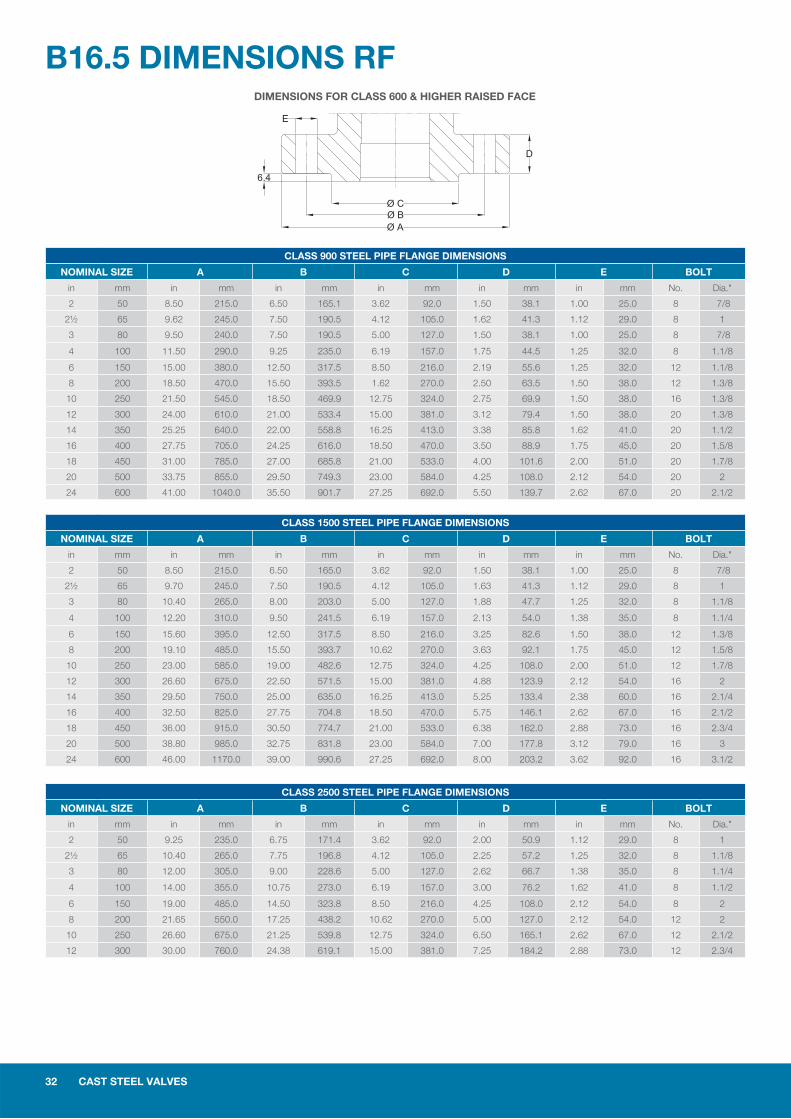
DIMENSIONS FOR CLASS 600 & HIGHER RAISED FACE
B16.5 DIMENSIONS RF
CLASS 900 STEEL PIPE FLANGE DIMENSIONS
NOMINAL SIZE A B C D E BOLT
in mm in mm in mm in mm in mm in mm No. Dia."
2 50 8.50 215.0 6.50 165.1 3.62 92.0 1.50 38.1 1.00 25.0 8 7/8
2½ 65 9.62 245.0 7.50 190.5 4.12 105.0 1.62 41.3 1.12 29.0 8 1
3 80 9.50 240.0 7.50 190.5 5.00 127.0 1.50 38.1 1.00 25.0 8 7/8
4 100 11.50 290.0 9.25 235.0 6.19 157.0 1.75 44.5 1.25 32.0 8 1.1/8
6 150 15.00 380.0 12.50 317.5 8.50 216.0 2.19 55.6 1.25 32.0 12 1.1/8
8 200 18.50 470.0 15.50 393.5 1.62 270.0 2.50 63.5 1.50 38.0 12 1.3/8
10 250 21.50 545.0 18.50 469.9 12.75 324.0 2.75 69.9 1.50 38.0 16 1.3/8
12 300 24.00 610.0 21.00 533.4 15.00 381.0 3.12 79.4 1.50 38.0 20 1.3/8
14 350 25.25 640.0 22.00 558.8 16.25 413.0 3.38 85.8 1.62 41.0 20 1.1/2
16 400 27.75 705.0 24.25 616.0 18.50 470.0 3.50 88.9 1.75 45.0 20 1.5/8
18 450 31.00 785.0 27.00 685.8 21.00 533.0 4.00 101.6 2.00 51.0 20 1.7/8
20 500 33.75 855.0 29.50 749.3 23.00 584.0 4.25 108.0 2.12 54.0 20 2
24 600 41.00 1040.0 35.50 901.7 27.25 692.0 5.50 139.7 2.62 67.0 20 2.1/2
CLASS 1500 STEEL PIPE FLANGE DIMENSIONS
NOMINAL SIZE A B C D E BOLT
in mm in mm in mm in mm in mm in mm No. Dia."
2 50 8.50 215.0 6.50 165.0 3.62 92.0 1.50 38.1 1.00 25.0 8 7/8
2½ 65 9.70 245.0 7.50 190.5 4.12 105.0 1.63 41.3 1.12 29.0 8 1
3 80 10.40 265.0 8.00 203.0 5.00 127.0 1.88 47.7 1.25 32.0 8 1.1/8
4 100 12.20 310.0 9.50 241.5 6.19 157.0 2.13 54.0 1.38 35.0 8 1.1/4
6 150 15.60 395.0 12.50 317.5 8.50 216.0 3.25 82.6 1.50 38.0 12 1.3/8
8 200 19.10 485.0 15.50 393.7 10.62 270.0 3.63 92.1 1.75 45.0 12 1.5/8
10 250 23.00 585.0 19.00 482.6 12.75 324.0 4.25 108.0 2.00 51.0 12 1.7/8
12 300 26.60 675.0 22.50 571.5 15.00 381.0 4.88 123.9 2.12 54.0 16 2
14 350 29.50 750.0 25.00 635.0 16.25 413.0 5.25 133.4 2.38 60.0 16 2.1/4
16 400 32.50 825.0 27.75 704.8 18.50 470.0 5.75 146.1 2.62 67.0 16 2.1/2
18 450 36.00 915.0 30.50 774.7 21.00 533.0 6.38 162.0 2.88 73.0 16 2.3/4
20 500 38.80 985.0 32.75 831.8 23.00 584.0 7.00 177.8 3.12 79.0 16 3
24 600 46.00 1170.0 39.00 990.6 27.25 692.0 8.00 203.2 3.62 92.0 16 3.1/2
CLASS 2500 STEEL PIPE FLANGE DIMENSIONS
NOMINAL SIZE A B C D E BOLT
in mm in mm in mm in mm in mm in mm No. Dia."
2 50 9.25 235.0 6.75 171.4 3.62 92.0 2.00 50.9 1.12 29.0 8 1
2½ 65 10.40 265.0 7.75 196.8 4.12 105.0 2.25 57.2 1.25 32.0 8 1.1/8
3 80 12.00 305.0 9.00 228.6 5.00 127.0 2.62 66.7 1.38 35.0 8 1.1/4
4 100 14.00 355.0 10.75 273.0 6.19 157.0 3.00 76.2 1.62 41.0 8 1.1/2
6 150 19.00 485.0 14.50 323.8 8.50 216.0 4.25 108.0 2.12 54.0 8 2
8 200 21.65 550.0 17.25 438.2 10.62 270.0 5.00 127.0 2.12 54.0 12 2
10 250 26.60 675.0 21.25 539.8 12.75 324.0 6.50 165.1 2.62 67.0 12 2.1/2
12 300 30.00 760.0 24.38 619.1 15.00 381.0 7.25 184.2 2.88 73.0 12 2.3/4
CAST STEEL VALVES 33
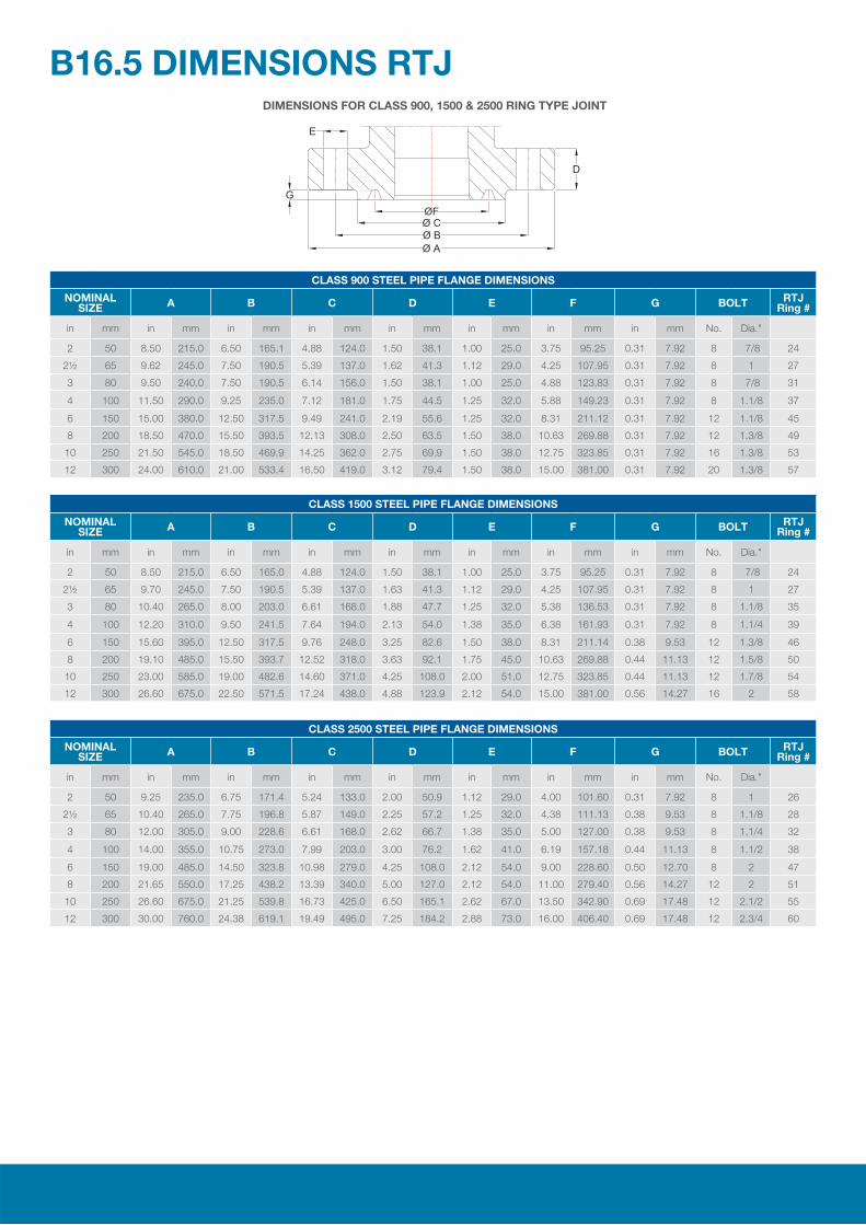
DIMENSIONS FOR CLASS 900, 1500 & 2500 RING TYPE JOINT
B16.5 DIMENSIONS RTJ
CLASS 900 STEEL PIPE FLANGE DIMENSIONS
NOMINAL SIZE A B C D E F G BOLT RTJ
Ring #
in mm in mm in mm in mm in mm in mm in mm in mm No. Dia."
2 50 8.50 215.0 6.50 165.1 4.88 124.0 1.50 38.1 1.00 25.0 3.75 95.25 0.31 7.92 8 7/8 24
2½ 65 9.62 245.0 7.50 190.5 5.39 137.0 1.62 41.3 1.12 29.0 4.25 107.95 0.31 7.92 8 1 27
3 80 9.50 240.0 7.50 190.5 6.14 156.0 1.50 38.1 1.00 25.0 4.88 123.83 0.31 7.92 8 7/8 31
4 100 11.50 290.0 9.25 235.0 7.12 181.0 1.75 44.5 1.25 32.0 5.88 149.23 0.31 7.92 8 1.1/8 37
6 150 15.00 380.0 12.50 317.5 9.49 241.0 2.19 55.6 1.25 32.0 8.31 211.12 0.31 7.92 12 1.1/8 45
8 200 18.50 470.0 15.50 393.5 12.13 308.0 2.50 63.5 1.50 38.0 10.63 269.88 0.31 7.92 12 1.3/8 49
10 250 21.50 545.0 18.50 469.9 14.25 362.0 2.75 69.9 1.50 38.0 12.75 323.85 0.31 7.92 16 1.3/8 53
12 300 24.00 610.0 21.00 533.4 16.50 419.0 3.12 79.4 1.50 38.0 15.00 381.00 0.31 7.92 20 1.3/8 57
CLASS 1500 STEEL PIPE FLANGE DIMENSIONS
NOMINAL SIZE A B C D E F G BOLT RTJ
Ring #
in mm in mm in mm in mm in mm in mm in mm in mm No. Dia."
2 50 8.50 215.0 6.50 165.0 4.88 124.0 1.50 38.1 1.00 25.0 3.75 95.25 0.31 7.92 8 7/8 24
2½ 65 9.70 245.0 7.50 190.5 5.39 137.0 1.63 41.3 1.12 29.0 4.25 107.95 0.31 7.92 8 1 27
3 80 10.40 265.0 8.00 203.0 6.61 168.0 1.88 47.7 1.25 32.0 5.38 136.53 0.31 7.92 8 1.1/8 35
4 100 12.20 310.0 9.50 241.5 7.64 194.0 2.13 54.0 1.38 35.0 6.38 161.93 0.31 7.92 8 1.1/4 39
6 150 15.60 395.0 12.50 317.5 9.76 248.0 3.25 82.6 1.50 38.0 8.31 211.14 0.38 9.53 12 1.3/8 46
8 200 19.10 485.0 15.50 393.7 12.52 318.0 3.63 92.1 1.75 45.0 10.63 269.88 0.44 11.13 12 1.5/8 50
10 250 23.00 585.0 19.00 482.6 14.60 371.0 4.25 108.0 2.00 51.0 12.75 323.85 0.44 11.13 12 1.7/8 54
12 300 26.60 675.0 22.50 571.5 17.24 438.0 4.88 123.9 2.12 54.0 15.00 381.00 0.56 14.27 16 2 58
CLASS 2500 STEEL PIPE FLANGE DIMENSIONS
NOMINAL SIZE A B C D E F G BOLT RTJ
Ring #
in mm in mm in mm in mm in mm in mm in mm in mm No. Dia."
2 50 9.25 235.0 6.75 171.4 5.24 133.0 2.00 50.9 1.12 29.0 4.00 101.60 0.31 7.92 8 1 26
2½ 65 10.40 265.0 7.75 196.8 5.87 149.0 2.25 57.2 1.25 32.0 4.38 111.13 0.38 9.53 8 1.1/8 28
3 80 12.00 305.0 9.00 228.6 6.61 168.0 2.62 66.7 1.38 35.0 5.00 127.00 0.38 9.53 8 1.1/4 32
4 100 14.00 355.0 10.75 273.0 7.99 203.0 3.00 76.2 1.62 41.0 6.19 157.18 0.44 11.13 8 1.1/2 38
6 150 19.00 485.0 14.50 323.8 10.98 279.0 4.25 108.0 2.12 54.0 9.00 228.60 0.50 12.70 8 2 47
8 200 21.65 550.0 17.25 438.2 13.39 340.0 5.00 127.0 2.12 54.0 11.00 279.40 0.56 14.27 12 2 51
10 250 26.60 675.0 21.25 539.8 16.73 425.0 6.50 165.1 2.62 67.0 13.50 342.90 0.69 17.48 12 2.1/2 55
12 300 30.00 760.0 24.38 619.1 19.49 495.0 7.25 184.2 2.88 73.0 16.00 406.40 0.69 17.48 12 2.3/4 60
2 CAST STEEL VALVES
6 Beardmore Way, Clydebank Industrial Estate,Clydebank , G81 4HT,Scotland, UKTel: (44) 141 435 7640Fax: (44) 141 435 7647Website: www.kvc-uk.comEmail: [email protected]
Exclusive Agent / Distributor / Stockist (Asia Pacifi c)Federal Hardware Engineering Co. Pte Ltd47/49 Genting RoadSingapore 349489Tel: (65) 67478118Fax: (65) 6743 0690/ 6745 0048Website: www.federal.com.sgEmail: [email protected]