Embed Size (px)
Citation preview

The City of Winnipeg Section 40 05 90.01 Specifications Page 1 of 4 Bid Opportunity No. 712-2013
CAST IRON SLIDE GATES AND APPURTENANCES
1. GENERAL
1.1 Description
.1 Provide and test cast iron slide gates and appurtenances as indicated in compliance with the Drawings.
1.2 References
.1 ASTM International (ASTM):
.1 A48/48M-03: Standard Specification for Gray Iron Castings.
.2 A276-13: Standard Specification for Stainless Steel Bars and Shapes.
.3 B21/B21M-12: Standard Specification for Naval Brass Rod, Bar, and Shapes.
.4 B584-13: Standard Specification f or Copper A lloy Sand Castings f or General Applications
.2 American Water Works Association (AWWA):
.1 C560-07: Cast-Iron Slide Gates.
1.3 Submittals
.1 Submit the following in accordance with Section E3 – Submittals and Shop Drawings:
.1 Provide Affidavit of Compliance, certifying that the gate conforms to the requirements of AWWA C560-07 and this Specification
.2 Certified shop and erection drawings. Contractor shall submit files of the proposed equipment in the capacity, size, and arrangement as indicated and specified.
.3 Data for gate and actuator characteristics and performance.
.4 Shop Drawing data for accessory items.
.5 Certified setting plans, with tolerances, for anchor bolts.
.6 Manufacturer's literature as needed to supplement certified data.
.7 Operating and maintenance instructions and parts lists.
.8 Certified results of gate shop testing.
.9 Certified results of actuator shop testing from the actuator manufacturer.
.10 List of recommended spare parts other than those specified.

The City of Winnipeg Section 40 05 90.01 Specifications Page 2 of 4 Bid Opportunity No. 712-2013
CAST IRON SLIDE GATES AND APPURTENANCES
.11 Shop and field inspection reports.
.12 Qualifications of field service staff.
.13 Shop and field testing procedures and set up
.14 Special tools.
2. PRODUCTS
2.1 System Description
.1 Gate size and location:
.1 SG-1000: 1050 mm x 1050 mm w ide sluice gate on influent 1050 LDS to pumping station.
2.2 Manufacturers
.1 Rodney Hunt
.2 Hydro Gate Company (Meuller Water Products, Inc.)
2.3 Gate Design and Construction
.1 All gates in conformance with AWWA C560-07 and as specified.
.2 Perform work in accordance with the best modern practice for the manufacture of high-grade machinery. Accurately machine all mounting and bearing surfaces so that they can be assembled without fitting, chipping or remachining. Parts t o conform accurately to the design di mensions and be f ree of defects i n workmanship or material that will im pair their service. Completely shop assemble all gates to insure proper fit and adjustment of all parts.
.3 Type: Rising stem with stop nut, flange back with standard bottom closure.
.4 Mounting: Type F wall thimble
.5 Unseating Head: Maximum design unseating head shall be from the invert of the gate to the ground floor of the pumping station which shall be a minimum of 10.2 meters (33.3 ft).
.6 Operator and Lift:
.1 Enclosed gear lift with pedestal
.2 Operator to be finished with a 50 mm x 50 mm square nut suitable for attachment of an electric portable drill for opening.
.3 Operator shall turn counter clock wise to open.
.7 Stem Cover:
The City of Winnipeg Section 40 05 90.01 Specifications Page 3 of 4 Bid Opportunity No. 712-2013
CAST IRON SLIDE GATES AND APPURTENANCES
.1 Gear lift to be complete with stem cover with acrylic window with gradations in suitable increments for the entire range of gate operation.
.8 Stem Guides:
.1 Adjustable in both the horizontal and vertical directions.
2.4 Materials
.1 Frame, Slide guides and yoke: ASTM A48/A48M-03 Gray Iron, Class 30
.2 Seating Faces: ASTM B21-12 Naval Bronze, Alloy 482
.3 Wall Thimble: ASTM A48/A48M-03 Gray Iron, Class 30
.4 Wedges: ASTM B584-13 Manganese Bronze, Alloy C865
.5 Wedge Blocks: ASTM A48/A48M-03, Gray Iron, Class 30
.6 Fasteners and Anchors: ASTM A276-13 Type 316 Stainless Steel
.7 Stem: ASTM A276-13 Type 304 Stainless Steel
.8 Stem Couplings: ASTM A276-13 Type 304 Stainless Steel
.9 Stem Guide: ASTM A48/A48M-03 Gray Iron, Class 30 with Bronze Bushings
.10 Operator Pedestal: ASTM A48/A48M-03 Gray Iron, Class 30 or Steel
.11 Stem cover: Aluminum or Galvanized Steel
2.5 Shop Testing
.1 The fully assembled gate shall be shop inspected, adjusted and tested for operation and leakage at the design head before shipping.
.2 Provide the following information to the Contract Administrator prior to delivery of sluice gate and operator assemblies:
.1 A certified copy of the Chemical and Physical Analysis on all materials used in the manufacture of the sluice gate, wall thimble, stems, operator and accessories or certification that the materials used are in strict accordance with this specification.
.2 Copies of the test reports for Performance and Leakage tests. Included on the report shall be the signature of the official who is respo nsible f or t he gate assembly and testing.

The City of Winnipeg Section 40 05 90.01 Specifications Page 4 of 4 Bid Opportunity No. 712-2013
CAST IRON SLIDE GATES AND APPURTENANCES
3. EXECUTION
3.1 Installation
.1 Install i tems i n ac cordance with ac cepted S hop Drawings, manufacturer's pri nted instructions and as indicated.
.2 Clean debris, dirt, and gravel, from inside of gates and channels before placing gates.
.3 Install slide gates in completely assembled condition with discs wedged lightly but firmly into seats with nuts pulled up tight.
.4 Erect and support gates and thimbles in respective positions free from distortion and strain on appurtenances during handling and installation.
.5 Inspect material for defects in workmanship and material.
.6 Clean out debri s and f oreign m aterial f rom gate opening and s eats, t est operat ing mechanisms to check proper functioning, and c heck nuts and bolts f or tightness. Repair gates and other equipment which do not operate easily or are otherwise defective.
.7 Set floorstand operators and stem guides so stems run smoothly in true alignment. Anchor guides firmly to walls. Check distances from centrelines of gates to operating level or base of floorstand and adjust if necessary to suit actual conditions of installation.
3.2 Field Testing
.1 Perform leakage test in the Contract Administrator’s presence once sluice gate has been installed to ensure compliance with the allowable leakage rate indicated in AWWA C560-07.
.2 Arrange for a qualified field representative of the sluice gates supplier/manufacturer to be present during field testing.
.3 Generally, the tests for unseating head will be performed by installing inflatable plugs MH.L22, f ill the chambers wit h water to the rim elevation of MH.L22 and measure the leakage rate t hrough the gates. Inflatable pl ugs s hall be i nflated f rom, anchored t o an d removable from the ground surface.
.4 The tests for the unseating head w ill be performed by closing the sluice gate filling the chamber with water to the specified head and measuring the leakage rate through the gate.
.5 The Contractor will be responsible to supply water from a hydrant into the chambers for testing purposes.
.6 If t he gates fail the field leakage tests, the Contractor shall be responsible for the cost associated t o repeat the tests, and shal l undertake all adjustments, replacements or other modifications necessary to facilitate the tests at their own expense. The sequence shall be repeated until the gates pass the allowable leakage rates.
END OF SECTION

The City of Winnipeg Section 40 05 90.02 Specifications Page 1 of 7 Bid Opportunity No. 712-2013
STAINLESS STEEL SLIDE GATES AND APPURTENANCES
1. GENERAL
1.1 Description
.1 Provide and test s tainless s teel sli de gates and appurt enances as indicated and in compliance with the Drawings.
1.2 References
.1 ASTM International (ASTM):
.1 A240/A240M-13a: Standard Specification f or Chromium and Chromium-Nickel Stainless Steel Plate, Sheet, and Strip for Pressure Vessels and for General Applications
.2 A276-13: Standard Specification for Stainless Steel Bars and Shapes.
.3 B584-13: St andard Spec ification for Copper Al loy Sand Ca stings for G eneral Applications.
.4 D2000-12: S tandard Cl assification System f or R ubber Pr oducts in Aut omotive Applications.
.5 D4020-11: Standard Specification f or U ltra-High-Molecular-Weight P olyethylene Molding and Extrusion Materials
.2 American Welding Society (AWS)
.1 AWS D1.6/D1.6M: Structural Welding Code— Stainless Steel.
.3 American Water Works Association (AWWA):
.1 C561-12: Fabricated Stainless Steel Slide Gates
1.3 Submittals
.1 Submit the following in accordance with Section E3 – Submittals and Shop Drawings:
.1 Provide Affidavit of Compliance, certifying that the gate conforms to the requirements of AWWA C561-12 and this Specification.
.2 Certified shop and erection drawings. Contractor shall submit files of the proposed equipment in the capacity, size, and arrangement as indicated and specified.
.3 Data for gate and actuator characteristics and performance.
.4 Shop Drawing data for accessory items.
.5 Certified setting plans, with tolerances, for anchor bolts.

The City of Winnipeg Section 40 05 90.02 Specifications Page 2 of 7 Bid Opportunity No. 712-2013
STAINLESS STEEL SLIDE GATES AND APPURTENANCES
.6 Manufacturer's literature as needed to supplement certified data.
.7 Operating and maintenance instructions and parts lists.
.8 Certified results of gate shop testing.
.9 Certified results of actuator shop testing from the actuator manufacturer.
.10 List of recommended spare parts other than those specified.
.11 Shop and field inspection reports.
.12 Qualifications of field service staff.
.13 Shop and field testing procedures and set up
.14 Special tools.
2. PRODUCTS
2.1 System Description
.1 Gate size and location:
.1 SLG-1010: 1250 mm high x 500 mm wide slide gate in sediment trap weir wall.
2.2 Manufacturers
.1 Fontaine Series 25 (Fontaine Industries Ltd.)
.2 Hydro Gate Company (Meuller Water Products, Inc.)
2.3 Gate Construction
.1 Gate to conform with AWWA C561-12 and as specified.
.2 Self-contained, rising stem, flush bottom type with self-adjusting seals.
.3 Gates with adjustable wedges or wedging devices are not acceptable.
.4 Provide all structural components 6 mm minimum thickness.
.5 Gate assemblies shall be media blasted prior to shipment to remove all mill scale, weld splatter, discoloration, or other surface imperfections.
.6 Assembly to consist of the following:
.1 Frame.
.2 Slide.

The City of Winnipeg Section 40 05 90.02 Specifications Page 3 of 7 Bid Opportunity No. 712-2013
STAINLESS STEEL SLIDE GATES AND APPURTENANCES
.3 Stem
.4 Seals.
.5 Benchstand with manual handwheel operator type.
.7 Materials:
.1 Frame Assembly and Retainers: ASTM A240/A240M-13a Type 316L stainless steel.
.2 Slides and Stiffeners: ASTM A240/A240M-13a Type 316L stainless steel.
.1 6 mm minimum thickness.
.3 Seat, seals and f acing: ASTM D4020-11 UHMW (Ultra-high Molec ular Weight Polyethylene
.4 Invert Seal for upward acting gates only: ASTM D2000-12 Neoprene or EPDM
.5 Stems: ASTM A276-13 Type 316 stainless steel.
.1 Minimum diameter: 38 mm.
.6 Lift Nuts: ASTM B584-13 Bronze
.7 Floorstand and Brackets: ASTM A276-13 Type 316L stainless steel
.8 Gear Operator Housing: Ductile iron
.9 Hardware, studs and nuts: ASTM A276-13 Type 316 stainless steel
.10 Anchor bolts: Type 316 stainless steel.
.8 Slide:
.1 Slide and reinforcing stiffeners welded to the slide.
.1 Stainless steel plate, minimum 6 mm.
.2 Reinforcement: Provide a minimum of two horizontal stiffeners welded to the slide and two vertical stiffeners welded to outside of the horizontal stiffeners.
.2 Provide the stem connector constructed of tw o angles or plates welded to the slide. Provide a minimum of two bolts connecting the stem to the stem connector.
.3 Deflection: Maximum o f 1/720 of the span or 1.6 m m w hichever is smaller, under design head specified.
.9 Seals:

The City of Winnipeg Section 40 05 90.02 Specifications Page 4 of 7 Bid Opportunity No. 712-2013
STAINLESS STEEL SLIDE GATES AND APPURTENANCES
.1 Provide a self-adjusting seal system suitable for the leakage and velocities specified herein, f requent cycling and m ounted such that there is no ob struction to the specified gate opening size.
.2 Provide gates equipped with UHMW polyethylene seat/seals to restrict leakage and to prevent metal to metal contact between the frame and slide.
.3 Extend the seat/seals to accommodate 1.50 times the slide height with the gate in the fully open or fully closed position.
.4 Provide all upward opening gates with a resilient seal for sealing the invert of the gate.
.5 Provide all seals mechanically fastened to the frame or slide, force fit seals or seals attached with adhesive are not acceptable.
.6 Gates using J” or “P” seals are not acceptable
.10 Frames:
.1 Provide frame assembly including guide members, invert members and yoke members constructed of formed stainless steel plate with a minimum thickness of 6 mm.
.2 Provide gussets to support the guide members for unseating gates as required by the design head specified and indicated.
.1 Provide gussets extended to supports the outer portion of the guide assembly and positioned to transfer the load to the anchor bolts or the wall thimble studs.
.3 Provide frame as follows:
.1 Bottom frame/invert member: Embedded
.2 Wall frame: Wall mounted with stainless steel anchor bolts and grout.
.4 Frame Guides and Invert Members:
.1 Provide the frame guides extending to accommodate the entire height of the slide when the slide is in the fully opened position on upward opening slide gates.
.2 For self-contained gates, provide a yoke across the top of the frame guides with the yoke formed by two structural members fixed to the top of the guides to provide a one-piece rigid frame.
.1 Provide the yoke designed to allow removal of the slide.
.5 Provide a rigid stainless steel invert member across the bottom of the opening.
.1 Invert member: Flush bottom ty pe on upward opening gates with a minimum weight as specified
.11 Stems:

The City of Winnipeg Section 40 05 90.02 Specifications Page 5 of 7 Bid Opportunity No. 712-2013
STAINLESS STEEL SLIDE GATES AND APPURTENANCES
.1 Provide a threaded operating stem to connect the operating mechanism to the slide.
.2 For rising stem gates provide the threaded portion engaging the operating nut in the manual operator.
.3 Minimum stem outside diameter of 38 mm.
.4 Stem extension pipes are not acceptable.
.5 Provide the stem constructed of solid stainless steel bar for the entire length.
.6 Tensile strength: Not less than 630 MPa for stems that are 75 mm diameter and smaller and not less than 595 MPa for stems larger than 75 mm.
.7 Provide the stem threaded to allow full travel of the slide unless otherwise specified or indicated.
.8 L/R: Not to exceed 200.
.9 Provide the stem, to withstand in tension the loads caused by a 177 N effort on the handwheel without exceeding 20 percent of the ul timate t ensile str ength of the stem material.
.10 Provide the stem, in tension, designed to withstand a load caused by a 177 N effort on the handwheel without exceeding 1/5 of the ultimate t ensile strength of the stem material.
.11 Provide stems of more than one piece joined by bronze or stainless steel couplings with the coupling bolted to the stem.
.12 Provide s tems on m anually operat ed gates with an adjustable s top col lar to pre vent over closing of the gate.
2.4 Stem Guides
.1 Provide stem gui des where required to maintain L/R of 200 or less for the unsupported length of the stem.
.2 Provide stem guides and brackets of Type 316L stainless steel.
.1 Adjustable in two directions
.2 Minimum Thickness: 6 mm.
.3 Bushings: UHMW or bronze
2.5 Manual Operators
.1 Provide a manual handwheel gate operator on a floor stand with no gear reduction.
.1 Material: Ductile iron housing

The City of Winnipeg Section 40 05 90.02 Specifications Page 6 of 7 Bid Opportunity No. 712-2013
STAINLESS STEEL SLIDE GATES AND APPURTENANCES
.2 Provide a threaded cast bronze lift nut to engage operating stem.
.3 Provide roller bearings above and below a flange on the operating nut to support both opening and closing thrusts.
.4 Operate gates under the operating head and design head, as specified and indicated, with no greater than a 177 N effort on the handwheel.
.2 Provide mechanical seals on the operating nut and the pinion shafts to exclude moisture and dirt and prevent leakage of lubricant out of the hoist mechanism.
.3 Provide lubricating fittings for the lubrication of all gears and bearings.
.4 Permanently attach or cast an arrow with the word "OPEN" on the handwheel indicating the direction of rotation to open the gate.
.5 Handwheels: 380 mm diameter and removable.
2.6 Shop Testing
.1 The fully assembled gate shall be shop inspected, adjusted and tested for operation and leakage at the design head before shipping.
.2 Provide the following information to the Contract Administrator prior to delivery of slide gate and operator assemblies:
.1 A certified copy of the Chemical and Physical Analysis on all materials used in the manufacture of the sluice gate, wall thimble, stems, operator and accessories or certification that the materials used are in strict accordance with this Specification.
.2 Copies of the test reports for Performance and Leakage tests. Included on the report shall be the signature of the official who is respo nsible f or t he gate assembly and testing.
3. EXECUTION
3.1 Installation
.1 Install items in accordance with shop drawings, manufacturer's printed instructions and as indicated.
.2 Clean debris, dirt, and gravel, from inside of gates and channels before placing gates.
.3 Install slide gates in completely assembled condition.
.4 Erect and support slide gates in positions free from distortion and strain on appurtenances during handling and installation.
.5 Inspect material for defects in workmanship and material.

The City of Winnipeg Section 40 05 90.02 Specifications Page 7 of 7 Bid Opportunity No. 712-2013
STAINLESS STEEL SLIDE GATES AND APPURTENANCES
.6 Clean out debri s and f oreign m aterial f rom gate opening and s eats, t est operat ing mechanisms to check proper functioning, and c heck nuts and bolts f or tightness. Repair gates and other equipment which do not operate easily or are otherwise defective.
.7 Set floorstand operators and stem guides so stems run smoothly in true alignment. Anchor guides firmly to walls. Check distances from centrelines of gates to operating level or base of floorstand and adjust if necessary to suit actual conditions of installation.
3.2 Field Testing
.1 Perform leakage test in the Contract Administrator’s presence once sluice gate has been installed to ensure compliance with the allowable leakage rate indicated in AWWA C561-12.
.2 Arrange for a qualified field representative of the sluice gates supplier/manufacturer to be present during field testing.
.3 Generally, the tests for seating head will be performed by filling the cell upstream of the weir to the weir elevation and measuring the leakage rate through the gate.
.4 Generally, the tests for unseating head will be performed by filling the cell downstream of the weir to the weir elevation and measuring the leakage rate through the gate.
.5 The Contractor will be responsible to supply water from a hydrant into the cell for testing purposes.
.6 If the gates f ail the f ield leakage tests due to a m anufacturing error, the supplier/manufacturer shall be responsible f or the cost associated to repeat the tests, and shall undertake all adjustments, replacements or other modifications necessary to facilitate the t ests at t heir own ex pense. The sequence shall be r epeated unt il the gat es pass the allowable leakage rates.
END OF SECTION

The City of Winnipeg Section 40 23 13.01 Specifications Page 1 of 8 Bid Opportunity No. 712-2013
PROCESS VALVES AND APPURTENANCES
1. GENERAL
1.1 Description
.1 Provide and process valves and appurtenances as indicated and in compliance with the Drawings.
.1 Provide sizes and capacities as indicated or specified.
1.2 References
.1 American National Standards Institute (ANSI)/American Society of Mechanical Engineers (ASME):
.1 ANSI/ASME B16.5-2013: Pipe Flanges and Flanged Fittings: NPS ½ through NPS 24 Metric/Inch Standard
.2 ANSI/ASME B16.10-2009: Face-to-Face and End-to-End Dimensions of Valves
.2 ASTM International (ASTM):
.1 ASTM A48/A48M-03 (2012): Standard Specification for Gray Iron Castings
.2 ASTM A126-04 (2009): Standard Specification for Gray Iron Castings for Valves, Flanges and Pipe Fittings
.3 ASTM A536-04 (2009): Standard Specification for Ductile Iron Castings
.3 American Water Works Association (AWWA):
.1 AWWA-C504-10: Rubber-Seated Butterfly Valves, 3 In. (75 mm) through 72 In. (1800 mm)
.2 AWWA-C509-09: Resilient-Seated Gate Valves for Water Supply Service
.3 AWWA-C542-09: Electric Motor Actuators for Valves and Slide Gates
.4 National Electrical Manufacturers Association (NEMA)
.1 ANSI/NEMA MG1-2011: Motors and Generators
.2 NEMA 250, Enclosures for Electrical Equipment (1000 Volts Maximum).
.3 NEMA ICS 6, Industrial Control and Systems: Enclosures
1.3 Submittals
.1 Submit the following in accordance with Section E3 – Submittals and Shop Drawings:
.1 Data, regarding valve characteristics and performance including Cv.

The City of Winnipeg Section 40 23 13.01 Specifications Page 2 of 8 Bid Opportunity No. 712-2013
PROCESS VALVES AND APPURTENANCES
.2 Shop Drawing data for accessory items.
.3 Manufacturer's literature as needed to supplement certified data.
.4 Operating and maintenance instructions and parts lists.
.5 Listing of re ference installations as specified with contact na mes and telephone numbers.
.6 Valve shop test results.
.7 Qualifications of field service technicians.
.8 Shop and field inspections reports.
.9 List of recommended spare parts other than those specified.
.10 Recommendations for short and long term storage.
.11 Special tools.
.12 Shop and field testing procedures and equipment to be used.
.13 Number of service technician days provided and per diem field service rate.
.14 Manufacturer’s product data and specifications for shop painting.
.15 Provide a layout drawing, plan and section showing orientation of plug, gate, check, ball valves and actuators and nearest obstructions for each valve.
.16 Manufacturer's product data and specifications for shop painting.
.17 Provide a li sting of the m aterials recommended f or each service specified and indicated. Provide documentation showing compatibility with process fluid and service specified and indicated.
.18 The latest ISO 9001 series certification or quality system plan.
.19 Material Certification:
.1 Provide certification from the equipment manufacturer t hat t he materials of construction speci fied ar e recommended and suitable for the serv ice conditions specified and i ndicated. If materials ot her than those specified are proposed based on incompatibility with the service conditions, provide technical data and certification that the proposed materials are recommended and suitable f or the service conditions specified and indicated including an installation list of a minimum of five (5) installations in operation for a minimum of five (5) years.
.2 Where materials are not specified, provide technical data and certification that the proposed materials are recommended and suitable f or the service conditions specified and indicated.

The City of Winnipeg Section 40 23 13.01 Specifications Page 3 of 8 Bid Opportunity No. 712-2013
PROCESS VALVES AND APPURTENANCES
1.4 Quality Assurance
.1 Provide enclosures for the area classifications specified and indicated.
.2 Services of Manufacturer’s Representative as specified herein.
.3 Manufacturer of valves and electric actuators shall ha ve a minimum of five (5) operating installations with valve and valve operators of the size specified and i n the same service as specified operating for not less than five (5) years.
.4 If equipment proposed is heavier, taller, different laying length or requires more operating space than specified and indicated; provide all structural, architectural, mechanical, electrical and plumbing revisions at no additional cost.
.1 If equipment is heavier than s pecified, t he Contractor shall provide a ll hoi sting equipment sized to maintain the minimum safety factor between the specified maximum equipment weight and the l ifting capacity of the hoisting equipment indicated and specified.
2. PRODUCTS
2.1 Butterfly Valves
.1 This Section applies to valves 1410, 1420, 1510 and 1520 as shown on the Drawings.
.2 Manufacturers:
.1 DeZurik, Inc.
.2 Tyco Flow Control
.3 Provide valves conforming to AWWA Standard C504 for Rubber Seated Butterfly Valves except as modified herein.
.4 Valves utilizing: Continuous rubber lining on the internal body surfaces and extending over the flanges, or a disk which sits at an angle to the axis of the pipe are acceptable.
.5 Valve Bearings: Self-lubricating, non-metallic material to effectively isolate the disk-shaft assembly from the valve body. Gray or ductile iron thrust or journal bearing surfaces are not acceptable.
.6 Class 150B valves except as specified or indicated.
.7 Valve Body: ASTM A126 Class B gray iron or ductile iron.
.1 Flanged short body lug valve.
.8 Valve Seats:
.1 EPDM
The City of Winnipeg Section 40 23 13.01 Specifications Page 4 of 8 Bid Opportunity No. 712-2013
PROCESS VALVES AND APPURTENANCES
.2 Provide seat mounted on body.
.9 Shaft: Type 316 stainless steel, one piece extending completely through disk.
.10 Shaft seal of the split-V type or O-ring type. Seal replaceable without disassembly of valve.
.11 Electric Valve Actuator
.1 The following is supplementary to AWWA C542.
.2 Electric actuator to be supplied and installed under this Contract shall be designed and manufactured by a company having at least five ( 5) years prior experience in manufacturing these types of products in the size as those specified herein.
.3 All technologies and devices used in the actuator shall have a minimum of five (5) years of commercial operating ex perience f or that specific m anufacturer. This i s to include torque and position sensing, lubrication, and electrical compartment design.
.4 Acceptable Products:
.1 Rotork IQ Pro Range
.5 Design Requirements:
.1 Valve Size: 100 mm butterfly valve
.2 Service: On-Off
.3 Opening: quarter-turn, Over-ride to be multi-turn, counter clockwise to open
.4 Electric Motor: 208 Volts AC Single Phase, 60 Hz Power Supply
.5 Service Temperature: -20°C to 60°C (-4°F to +140°F)
.6 Environment: Actuator shall be certified for use in hazardous area to CSA C22.2 No. 30 Explosion-Proof Enclosures for Use in Class 1 Zone 1 Hazardous Locations.
.6 Actuator Sizing
.1 Electric actuator shall be sized to provide the torque required to close or open the butterfly valve f or full bi-directional flow. The m aximum thrust output of the actuator shall not exceed the valve and stem shaft torque capability.
.7 Mounting:
.1 Electric actuator shall be designed and constructed for remote mounting within the intermediate level of the wet well chamber as sho wn on Drawings. A ctuator shall be supplied with 316 stainless steel mounting bracket and fasteners to be attached to t he i nterior wall of the c hamber. Bracket shall be de signed t o support and

The City of Winnipeg Section 40 23 13.01 Specifications Page 5 of 8 Bid Opportunity No. 712-2013
PROCESS VALVES AND APPURTENANCES
restrain the actuator under anticipated static and dynamic loads. Bracket shall be fastened using chemical adhesive type anchors.
.8 Motor
.1 Motor shall be CSA Certified, single phase capacitor run/start reversing squirrel cage induction type motor with Class ‘F’ insulated windings incorporating thermostat protection.
.2 Suitable for operation at 10% above or below normal 208 Volt and at 5% above or below 60 cycle power supply.
.3 Motor bearings shall be permanently lubricated.
.9 Manual Operation
.1 Actuator shall be provided with a handwheel, which shall not rotate during motor operation. The handwheel operation shal l be accomplished by a dec lutch l ever, capable of l ockout by padlock and r equire no greater than a 177 N eff ort on the handwheel. The handwheel shall disengage automatically from the operating mechanism once the motor is capable of operation.
.10 Integral Starter and Transformer
.1 The reversing starter, control transformer, and local controls shall be integral with the valve actuat or, suitably housed to prevent breat hing and conden sation bui ld-up. The starter shall be solid state type suitable for sixty (60) starts per hour, and of rating appropriate to m otor size. It shall have t he necessary tappings and be adequately rated to provide power f or energization of t he contactor coils, 24 Volt DC output where required f or remote controls, and f or supply f or all the internal electrical circuits.
.2 The windings shall be protected by easily replaceable fuses.
.11 Turns Limit and Torque Limit Switches to be adjustable as follows:
.1 Position setting range: 2.5 to 100,000 turns, w ith resolution to 15° of act uator output.
.2 Torque setting: 40% to 100% rated torque.
.3 Torque sensing shall be by purely electric or electronic methods. Extrapolation of torque from mechanically measured motor speed will not be acceptable.
.12 Remote Valve Position Indication
.1 Four contacts shall be provided to indicate fully open and fully closed positions, local selected, and thermostat tripped.
.2 Contacts to be rated at 5A, 250 VAC, 30 DC.

The City of Winnipeg Section 40 23 13.01 Specifications Page 6 of 8 Bid Opportunity No. 712-2013
PROCESS VALVES AND APPURTENANCES
.3 Analog position feedback shall be provided with 4-20 mA output proportional to position.
.13 Push Buttons and Selector Switches
.1 Actuator shall be complete with a local Open-Stop-Close push-button station with external Red-Open, Green-Closed and Yellow-Mid-Travel indicating li ghts and a Local-Off-Remote selector switch padlockable i n any one of the f ollowing three positions:
.1 Local Control Only
.2 Off/No Electrical Operation
.3 Remote Control
.2 The internal control and monitoring circuits shall operate at nominal 24 Volt DC or 120 Volt AC. User cont rol interface shall operate at 120 Volt AC. All necessary transformers shall be provided.
.3 User control interface shall be located inside the control room.
.14 Monitoring Facilities
.1 Facilities shall be provided for monitoring actuator operation and availability as follows:
.1 Motor (availability) relay, having one normally open contact, the relay being energized from the control transformer only when the Local/Off/Remote selector switch is in the remote position to indicate that the actuator is available for remote operation.
.2 Where required, it shall be possible to provide indication of thermostat trip and "Remote" selected as discrete signals.
.2 Wiring and Terminals
.1 Internal w iring shall be of CSA Certified insulated stranded cable of appropriate size for the control and single phase po wer. Each wire shall be cl early i dentified at each end. Permanent heat shrunk labelling shal l be used.
.2 The terminals shall be embedded in terminal block of high tracking-resistance compound.
.3 The terminal compartment shall be separated from the inner electrical components of the actuator by means of a watertight 'O' ring seal.
.4 The terminal co mpartment o f t he actuator shall b e provided with a minimum of two (2) threaded cable entries.
The City of Winnipeg Section 40 23 13.01 Specifications Page 7 of 8 Bid Opportunity No. 712-2013
PROCESS VALVES AND APPURTENANCES
.5 All w iring supplied as part of the actuator shall be contained within the main enclosure for physical and environmental protection. External conduit connections between components will not be acceptable.
.6 Control logic circuit boards and relay boards shall be mounted on plastic mounts to comply with double insulated standards. No more than a single primary size fuse shall be provided to minimize the need to remove single covers for replacement.
.7 A durable terminal identification card showing plan of terminals shall be attached to the inside of the terminal box cover indicating:
.1 Serial number
.2 External voltage values
.3 Wiring diagram number
.4 Terminal layout
.8 The identification card shall be suitable to inscribe cable core identification alongside terminal numbers.
.3 Enclosure
.1 Actuators shall be rated to operate in a Class 1 Zone 1 area complete with O-ring sealed, watertight to NEMA 6 as wel l as hav e an i nner watertight and dustproof O-ring seal between the terminal compartment and the internal electrical elements of the actuator, f ully protecting the switch mechanism, motor and al l other internal electrical elements of the actuator f rom ingress of moisture and dust when the terminal cover i s removed on site for cabling.
.2 Actuators shall be provided with an internal motor and compartment heater.
.3 All external fasteners shall be of 316 stainless steel.
.4 Start-up Kit
.1 Each actuator shall be supplied with a start-up kit comprising installation instructions, electrical wiring diagram, and suff icient space cover screws and seals to make good any site losses during the commissioning period.
2.2 Duck Bill Check Valves (CV1430, 1530, 2120, 2220)
.1 This section applies to check valves 1430, 1530, 2120 and 2220 as shown on the Drawings.
.2 Manufacturers:
.1 Tideflex, Series 35 (Tide Flex Technologies Division of Red Valve Company, Inc.)

The City of Winnipeg Section 40 23 13.01 Specifications Page 8 of 8 Bid Opportunity No. 712-2013
PROCESS VALVES AND APPURTENANCES
.3 Stormwater Service:
.1 Material: EPDM
.1 Provide flanged type valve with Type 316 stainless steel hardware.
.2 Flanges to conform to ANSI/ASME B16.5-2013.
3. EXECUTION
3.1 Installation
.1 Prior to installation, protect stored valves and appurtenances from damage due to exposure to sunlight, heat, dirt, debris, freezing and thawing, vandalism, etc.
.2 Clean all debris, dirt, gravel, etc, from inside of piping before placing valves in place.
.3 Erect and s upport v alves in respectiv e pos itions free from distortion and strain on appurtenances during handling and installation. Inspect material for defects in workmanship and m aterial. Clean out debris and foreign m aterial f rom valve openi ngs and seats, test operating mechanisms to check functioning, and check nuts and bolts for tightness.
.4 Set plum b and support valves in conformance with instructions of manufacturer. Shim valves m ounted on f ace of concrete vertically and grout in pl ace. Install valves i n control piping for access.
3.2 Field Testing
.1 Pressure test valves with pipeline pressure testing.
.2 Test functions of each valve.
.3 Make all adjustments necessary to place valves in specified working order at time of above tests.
3.3 Field Touch-Up Painting
.1 After installation and accepted testing by the Contract Administrator, apply touch-up paint to all scratched, abraded and damaged shop pai nted surfaces. Coating type and colour shal l match shop painting
END OF SECTION

The City of Winnipeg Section 40 23 19.01 Specifications Page 1 of 5 Bid Opportunity No. 712-2013
PROCESS PIPE HANGARS & SUPPORTS
1. GENERAL
1.1 Work Included
.1 Supply and installation of hangers and supports for all piping systems specified in Section 40 23 19.03. This section does not include pipe support for HVAC piping, pipe anchors, guides or seismic restraints.
1.2 References
.1 Manufacturers Standardization Society of the Valve and Fittings Industry (MSS):
.1 MSS SP 58-2009: Pipe Hangers and Supports – Materials, Design, Manufacture, Selection, Application, and Installation.
1.3 Submissions
.1 Submit the following for information in accordance with Section E3 - Submittals and Shop Drawings:
.1 In piping layout drawings specified in Section 40 29 19.03, indicate hanger and support locations and provide l egend summarizes load i nformation and hanger and support component selection at each location.
1.4 Service Conditions
.1 The intent of the drawings has been to indicate general arrangements and typical spacings for pipe systems, but does not r elieve the Contractor of t he responsibility for the design and supply of a complete and adequate support system.
.2 Provide hangers and s upports specified in this Section to resist pipe loads occurring primarily in the downward (gravity) direction.
1.5 Hanger and Support Selection
.1 Select pipe hangers and supports as specified in this Section.
.2 Review the piping layout in relation to the surrounding structure and adjacent piping and equipment before selecting the type of support to be used at each hanger point.
.3 Hangers and supports shall withstand all static and specified dynamic conditions of loading to which the piping and associated equipment may be subjected. As a minimum, consideration shall be given to following conditions:
.1 Weights of pipe, valves, fitting, insulating materials, suspended hanger components, and normal fluid contents.
.2 Weight of hydrostat ic test fluid or cleaning fluid if nor mal operating fluid contents are lighter.

The City of Winnipeg Section 40 23 19.01 Specifications Page 2 of 5 Bid Opportunity No. 712-2013
PROCESS PIPE HANGARS & SUPPORTS
.3 Reaction forces due to the operation of safety or relief valves.
.4 Size hangers and supports to fit the outside diameter of pipe or tubing.
.5 Where negligible movement occurs at hanger locations, use rod hanger s for suspended lines, whenever practical. Use bases, brackets or structural cross m embers f or piping supported from below.
.6 Hangers for the suspension of pipe and tubing sizes, 65 mm and larger shall be capable of vertical hanger component adjustment under load.
.7 Provide the supporting systems to allow for free or intended movement o f t he piping including its movement in relation to that of connected equipment.
.8 Design the system to support the operating loads with a safety factor of 5.0.
.9 Where there is horizontal movement at a suspended-type hanger location, select hanger components to allow for swing. The vertical angle of the hanger rod shall not, at any time, exceed 4 degrees.
.10 No cont act i s allowed between a pi pe and hanger or support components of di ssimilar metals. Prevent contact between dissimilar m etals when supporting copper tubing with copper-plated, rubber, plastic or vinyl coated, or stainless steel hanger and support components.
.11 Do not support piping from masonry wall construction.
.12 Do not attach pipe support components to equipment or pressure vessels unless otherwise specified.
.13 Use stock hanger and support components wherever practical.
.14 Provide s upplementary str uctural m embers, w here st ructural bearings are not i n s uitable locations.
.15 Make provision for expansion, contraction, slope and anchorage.
.16 Where necessary, pi pe support sy stems shall wit hstand the addit ional load of el ectrical or instrumentation t rays. Coordinate wit h other Divisions. Design and provide support system accordingly.
2. PRODUCTS
2.1 Acceptable Manufacturers
.1 The following manufacturer’s products to provide the specified features and to meet specified operating conditions:
.1 Anvil International (Mueller Water Products, Inc.)
.2 Taylor Pipe Supports (L.E. Taylor Associates Ltd.)

The City of Winnipeg Section 40 23 19.01 Specifications Page 3 of 5 Bid Opportunity No. 712-2013
PROCESS PIPE HANGARS & SUPPORTS
.2 Support Spacing:
Maximum Pipe Size : mm Maximum Spacing Steel: m up to 30 2.1 30-40 2.1 40-50 2.1 60-75 3.0 100 3.7 150 4.3 200 4.6 250 4.9
2.2 Materials
.1 Unless otherwise specified, pipe hangers and supports, structural attachments, fittings and accessories shall have a galvanized finish.
2.3 Pipe Hangers and Supports
.1 Clevis Pipe Hanger: Provide carbon steel clevis hangars and threaded rod with galvanized finish as follows:
.1 Anvil International, Figure 260 and Figure 140.
.2 Taylor Pipe Supports: #24Z and #54.
.2 Offset Pipe Clamp: Provide carbon steel pipe clamps with galvanized finish as follows:
.1 Anvil International, Figure 103.
.2 Taylor Pipe Supports, #87
2.4 Structural Attachments:
.1 Malleable Iron Concrete Insert: Provide malleable iron concrete inserts with galvanized finish as follows:
.1 Anvil International: Figure 282.
.2 Taylor Pipe Supports: #81.
.2 Welded Steel Bracket: Provide carbon steel brackets with galvanized finish as follows:
.1 Anvil International: Figure 199.
.2 Taylor Pipe Supports: #802.

The City of Winnipeg Section 40 23 19.01 Specifications Page 4 of 5 Bid Opportunity No. 712-2013
PROCESS PIPE HANGARS & SUPPORTS
3. EXECUTION
3.1 Hangar and Support Location
.1 Locate hangers and supports as near as possible to concentrated loads such as valves, flanges, etc. Locate hanger s, supports and accessories within t he m aximum span l engths specified on drawings to support continuous pipeline runs unaffected by concentrated loads.
.2 Provide hangers and/or base supports within 1.0 m of each change in direction on each leg, on one side of each v alve, and on the fi rst spool piece or f itting extending from a piece of equipment.
.3 Locate hangers and s upports to ensure that connections to equipment, tanks, etc. are substantially free from loads transmitted by the piping.
.4 Ensure that where piping is connected to equipment, a valve, piping assembly etc. that will require removal for m aintenance, the piping w ill be supported in such a manner that temporary supports will not be necessary for this procedure.
.5 Support piping so that no pockets will be formed in the span due to sagging of t he pipe between supports caused by the weight of the pipe, its contents, its insulation, its valves or its fittings.
.6 Install spring hangers where required to offset expansion in horizontal runs which follow long vertical risers.
3.2 Installation
.1 Do not use hanger components for purposes other than for which they were designed. Do not use hanger components for rigging and erection purposes.
.2 Install items to be embedded before concrete is poured. Fasten embedded items security to prevent movement when concrete is poured.
.3 Use embedded anchor bolts instead of concr ete inserts for support installation in areas below water surface or normally subjected to submerging.
.4 All minor modifications to accommodate installed equipment and structural components are subject to r eview. Do not commence work on r elated pi ping until written acceptance has been received.
.5 Include any piping support modifications on the shop drawings submitted prior to fabrication or installation.
.6 Prior to installation, inspect and field measure to ensure that previous work is not prejudicial to the proper installation of process piping.
.7 Provide plastic or rubber end caps at the exposed ends of all framing channels that are located up to 2100 mm above the floor.

The City of Winnipeg Section 40 23 19.01 Specifications Page 5 of 5 Bid Opportunity No. 712-2013
PROCESS PIPE HANGARS & SUPPORTS
.8 Review the drawings prior to installation of piping, conduit, and fixtures by this or any other division. Identify any conflicts and con firm the routing of each section of pipe work prior to commencement of installation. Advise of any conflicts with existing services. Where necessary, amend the routing of pipework to avoid conflict and provide shop drawings showing proposed routing.
3.3 Adjustment
.1 Adjust hangers and supports to obtain required pipe slope and elevation. Use shims made of material that is com patible wit h t he pi ping m aterial. Adj ust stanchions prior to gr outing of baseplates.
END OF SECTION

The City of Winnipeg Section 40 23 19.03 Specifications Page 1 of 6 Bid Opportunity No. 712-2013
STEEL PROCESS PIPE AND FITTINGS
1. GENERAL
1.1 Description
.1 Provide and test 250 mm and smaller diameter steel pipe, fittings and appurtenances as indicated and in compliance with the Drawings.
1.2 Design Requirements
.1 The design has been completed to the degree necessary for the Contractor to tender the project. I t i s not f ully detailed and will require the Contractor to under take some design of several aspects for the piping systems to be installed.
.2 Piping and Instrumentation drawings, piping schematics, and piping layout drawings are contained in the drawing set. The Piping and Instrumentation Drawings (P&IDs) indicate all major pipework, v alves, and appur tenances (other than c leanouts, purge points, etc.). The layout drawings indicate the Contract Administrator’s concepts and are intended to il lustrate a constructible method for the piping systems. Some appurtenances, supports, guides and anchors, and expansion joints are not f ully shown. The Contractor’s design will complement and detail these drawings.
.3 It is understood that some conflicts may arise that will require that the Contractor to re-route some of his piping to allow for the installation of wiring, ventilation duct, or similar.
.4 The Contractor is required to engage a competent engineer to be responsible for the final aspects of the desi gn. The c omponents of the desi gn t hat will be gener ated wi ll be as follows:
.1 Final layout, illustrated using layout and isometric drawings.
.2 Piping support system design, including details and spacing of all supports. The support system will ensure that the weight of the pipework and the need for lateral and vertical support are considered fully.
.3 Expansion and contraction design, including the layout and details for all necessary expansion joints needed to compensate for thermal expansion and contraction, structural movement, and the isolation of equipment.
.5 Design documentation will be submitted to the Contract Administrator as necessary to indicate compliance with the requirements of the piping systems. The documentation will be stamped and sealed by a Professional Engineer registered in the Province of Manitoba.
1.3 References
.1 ASTM International (ASTM):
.1 ASTM A53/A53M-12: Standard Specification for Pipe, Steel, Black and Hot-Dipped, Zinc-Coated, Welded and Seamless.

The City of Winnipeg Section 40 23 19.03 Specifications Page 2 of 6 Bid Opportunity No. 712-2013
STEEL PROCESS PIPE AND FITTINGS
.2 ASTM A123/123M-12: Standard Specification for Zinc (Hot-Dip Galvanized) Coatings on Iron and Steel Products.
.3 ASTM A276-13: Standard Specification for Stainless Steel Bars and Shapes.
.4 ASTM A536-84 (2009): Standard Specification for Ductile Iron Castings
.2 American Society of Mechanical Engineers (ASME):
.1 ASME -B1.1-2003: Unified Inch Screw Threads (UN and UNR Thread Form).
.2 ASME -B16.5-2013: Pipe Flanges and Fl anged Fittings: NPS ½ through NPS 24 Metric/Inch Standard
.3 ASME-B18.2.2-1987: Nuts for General A pplications: Machi ne Screw Nuts, Hex , Square, Hex Flange, and Coupling Nuts (Inch Series).
.3 Canadian Standards Association (CSA)
.1 CSA-W47.1-09 Certification of Companies for Fusion Welding of Steel
.2 CSA-W59-03 (2008) Welded Steel Construction (Metal Arc Welding).
1.4 Submittals
.1 Submit the following in accordance with Section E3 – Submittals and Shop Drawings:
.1 Shop Drawings stamped and signed by a Professional Engineer registered or licensed in t he P rovince of Manitoba i n ac cordance with S ection E 3 – Submittals and S hop Drawings of the piping layout including the following.
.1 Pipe layouts in full detail.
.2 Location of hangers and supports.
.3 Location and type of anchors.
.4 Location of couplings and expansion joints.
.5 Details of all wall penetrations and fabricated fittings or special fittings.
.6 Schedules of pipe, fittings, expansion joints and other appurtenances.
.2 Sworn certificates in duplicate of shop tests showing compliance with appropriate standard.
.3 Catalog cuts of joints, couplings, harnesses, expansion joints, gaskets, fasteners and other accessories.
.4 Brochures and technical dat a on coatings and linings and proposed method for application and repair.

The City of Winnipeg Section 40 23 19.03 Specifications Page 3 of 6 Bid Opportunity No. 712-2013
STEEL PROCESS PIPE AND FITTINGS
.5 Provide tag names and numbers for all sections of piping and fittings.
.2 Material Certification:
.1 Provide certification from the piping and fittings manufacturer that the materials of construction specified are recommended and designed for the service conditions specified and indicated.
.2 Where materials are not specified, provide technical data and certification that the proposed materials are recommended and designed for the service conditions specified and indicated.
2. PRODUCTS
2.1 Materials
.1 Steel pipe: ASTM-A53/A53M, Type ERW or S, Grade B, Black Steel, Schedule 40.
2.2 Pipe
.1 Fabricate to sizes, dimension, and shapes indicated
.2 Sizes, Pipe, Fittings and Specials: Nominal
2.3 Grooved End Fittings
.1 All fittings shall be grooved type ductile iron fittings with hot dipped galvanized finish.
.2 Provide long sweeping elbows to 1 ½ times the nominal diameter.
.3 Housing:
.1 Conforms to ASTM A536 ductile iron
.4 Gaskets:
.1 EPDM
.5 Acceptable manufacturers:
.1 Victaulic
2.4 Flanges
.1 Provide Class 150 steel flanges in accordance with ASME B16.5.
.2 Provide flanged end pipe fitted with slip-on flanges. Provide longitudinal or spiral w elds ground flush to accommodate type of flanges provided.

The City of Winnipeg Section 40 23 19.03 Specifications Page 4 of 6 Bid Opportunity No. 712-2013
STEEL PROCESS PIPE AND FITTINGS
.1 Provide bolts and bolt-studs in accordance with ASTM A276, Type 316 with hexagonal or square heads, coarse thread fit, threaded full length with ends c hamfered or rounded.
.2 Project bolt ends 6 mm beyond surface of nuts.
.3 Provide hexagonal nuts with dimensions in accordance with ASME B18.2.2 and coarse threads in accordance with ASME B1.1.
.3 Provide flanges tested, after welding to pipe, for true plane and reface, to bring them within specified tolerances.
.4 Blind Flanges: Conforming in diameter, drilling, and thickness to flanges to which they mate and reinforced to produce a watertight joint under test pressures.
.5 Gaskets:
.1 Materials:
.1 EPDM
2.5 Welding
.1 All steel welding shall conform to CSA Standard W59. The fabricator shall be fully approved by the Canadian Welding Bureau, in conformance with CSA Standard W47.1. Welding shall be done by currently licensed welder s onl y. Welding spatter and other fabricator burrs where exposed shall be ground or filed smooth and left ready for subsequent operations.
2.6 Couplings
.1 Joints for piping:
.1 Provide grooved couplings only with hot dipped galvanized finish.
.2 Acceptable Product: Victaulic Style 07 Zero-Flex Rigid Coupling (Victaulic Company)
.3 Provide lugs and washers in accordance with ASTM A276 Type 316.
.4 Nuts and bolts:
.1 Provide bolts and bolt-studs in accordance with ASTM A276 Type 316 and ASME B1.1 with hexagonal or square heads, coarse thread fit, t hreaded full length with ends chamfered or rounded.
.2 Project bolt ends 6 mm beyond surface of nuts.
.3 Provide hexagonal nuts with dimensions in accordance with ANSI B18.2.2 and coarse threads in accordance with ASME B1.1.
.5 Gaskets:

The City of Winnipeg Section 40 23 19.03 Specifications Page 5 of 6 Bid Opportunity No. 712-2013
STEEL PROCESS PIPE AND FITTINGS
.1 Materials:
.1 EPDM
2.7 Structural Element Penetrations
.1 Wall and floor penetration locations and de tails are s hown on the Process Mechanical Drawings. Where a structural element penetration is not referenced, conform to the Standard Detail relevant to the type of structure, exposure and type of pipe.
.2 Provide pipe and pipe sleeves capable of supporting the loads applied during placement of concrete or during blockwork erection.
.3 Supply wall or floor penetrations into submerged areas, under slab areas, and where shown with a water stop flange as shown on the Drawings. Continuously weld the water stop flange, both sides, onto the pipe. Fill annular space between the sleeve and pipe, where a sleeve is used, with non-shrink grout. Form reglets between the grout and the concrete and between the grout and the pipe, on "wet" sides of the wall penetration. Fill reglet with sealant.
3. EXECUTION
3.1 Installation of Pipe
.1 Before assembly, remove debris from inside pipes and fittings.
.2 Before flanged piec es are a ssembled, rem ove rus t re sistant coat ing from machined surfaces, clean gaskets and smooth burrs. Make up f langed joints tight, and prevent strain upon valves or other pieces of equipment.
.3 Bolt threads must fully engage the nuts. At a minimum the bolt must be flush with the nut and no more than 13 mm excess thread protruding from the nut.
.4 Install tierods, pipe clamps or bridles when sleeve type couplings or fittings are used in piping system, and at changes i n direction or other pl aces t o prevent j oints from pulling apart.
.5 Examine pieces for damage. Do not install pieces that are damaged according to Contract Administrator. If any damaged piece should be discovered after having been installed, remove and replace with a sound piece at no additional cost.
.6 Handle pipe with equipment such as nylon slings and padded skids, designed to prevent damage to the coating. Repair abrasions and injuries to the coating.
3.2 Lining and Coating
.1 Apply hot dip galvanizing coating in accordance with ASTM A123/A123M-12 to all s teel process pipe after test fitting to a minimum net retention of 610 g/m2.
3.3 Installation of Pipe Supports
.1 Provide in accordance with Section 40 23 19.01.

The City of Winnipeg Section 40 23 19.03 Specifications Page 6 of 6 Bid Opportunity No. 712-2013
STEEL PROCESS PIPE AND FITTINGS
.2 Proceed with installation of p ipe supports only after required building structural w ork has been completed and concrete has reached its 28 day compressive strength.
.3 Support piping to prevent forces applied on valves and equipment.
3.4 Physical Checkout, Field and Functional Testing
.1 Give the Contract Administrator 24 hours’ notice prior to testing.
.2 Clean dirt, dust, oil, grease and other foreign material, before pressure and leakage tests.
.3 Water for testing shall be provided by the Contractor.
.4 Pressure and Leakage Tests shall be done as follows:
.1 Provide temporary testing plugs or caps; pressure pumps, pipe connections, meters, gauges, equipment, and labour.
.2 Provide all temporary thrust restraints necessary for testing. Remove upon completion of testing.
.3 Test pipelines in sections of accepted length.
.4 Fill section of pipe with water and expel air.
.5 Process piping shall be tested at normal operating pressure plus 300 kPa (45 psi) or 550 kPa (80 psi) water pressure, whichever is greater, measured at the low point in the system or as specified otherwise.
.6 No visible leakage in joint is acceptable.
.7 If unable to achieve and maintain specified pressure for one hour with no additional pumping, section has failed to pass test.
.8 If s ection fails pressure and/or leakage test, locate, uncover, and repair or replace defective pipe, f itting, or j oint, and conduct additional tests and repairs unt il section passes test at no additional cost and without any time extensions.
.5 Make piping connections to equipment with pipe in a free supported state and without application of vertical or horizontal forces to align piping with the equipment flanges.
END OF SECTION

The City of Winnipeg Section 40 90 00 Specification Page 1 of 15 Bid Opportunity No. 712-2013
COMMON WORK RESULTS FOR INSTRUMENTATION AND CONTROL FOR PROCESS SYSTEMS
1. GENERAL
1.1 Work
.1 Supply, install, commission, provide warranty, and fully document a complete instrumentation and control (I&C) system as shown on the Drawings and as specified herein. The I&C system contains vendor component subsystems specified in this and other Sections of the Specification.
.2 Component subsystems of the I&C system will include, but are not limited to, the following:
.1 Primary elements and transmitters
.2 Final control elements
.3 I&C field devices
.4 I&C junction boxes and marshalling panels
.5 Control panels
.6 Instrumentation cabling
.7 Instrumentation power supplies
.8 Conduit and cable tray
.3 The Contractor’s responsibility also includes receiving, uncrating, examining for shortages or damage, assembling, f ield fi tting, installing, mounting, wiring and testing of vendor supplied component subsystems.
.4 Where packaged, stand-alone control systems are supplied under other Divisions of this Specification, provide c abling t o c onnect to t he r equired r emote m onitoring and/ or control functions. Provide end-to-end Commissioning of all required remote m onitoring and/or control functions. Ensure the correct f unctionality o f any equipment supplied under other Divisions of this Specification.
.5 Documentation referred to in 1.1.1 to include as a minimum:
.1 Equipment descriptive data
.2 Equipment installation, service manuals, O&M Manuals and recommended spare parts lists.
.3 Schematics and interconnection wiring diagrams sealed by a Professional Engineer registered in the Province of Manitoba.
.4 Records of conductor identification, field terminals, changes, etc.
.5 Instrumentation and control panel Shop Drawings, face layouts, schematics and point-to-point wiring diagrams sealed by a Professional Engineer registered in the Province of Manitoba.

The City of Winnipeg Section 40 90 00 Specification Page 2 of 15 Bid Opportunity No. 712-2013
COMMON WORK RESULTS FOR INSTRUMENTATION AND CONTROL FOR PROCESS SYSTEMS
.6 Submit individual Loop Draw ings for each device based on the provided typical Drawings.
.7 Records of as-built information for the complete instrumentation system.
.6 Documentation provided is formatted as follows:
.1 Piping & Instrumentation Diagrams (P&IDS) – depict the general intent of the control systems.
.2 Instrument Index – an index of the detailed information for the main devices shown on the P&IDs. The i ndex lists t he appropriate support documentation f or the devices’ supply and installation. The instrument index is the controlling document for the supply of materials.
.3 Input/Output (I/O) Index – an index o f the control s ystem I/ O points shown on the P&IDs, giving the supporting documentation as per the instrument index.
.4 Instrument Specification Sheet – detail the relevant data for the supply of devices.
.5 Instrument Loop Diagrams (ILDs) – s how typical interconnections and hook-up of devices. The Contractor is to reproduce an ILD for each device and record al l relevant as-built information on each sheet for submission at the completion of the Work. Fill in all terminal and wiring numbers etc. from the Shop Drawings as they become available. A set of ‘B’ size (11 x 17) ACAD Drawings and associated files will be made available to the successful Contractor.
.6 Location Drawings – indicate in plan and/or elevation views where the instrument elements are physi cally located. These Drawings are provided to assist the Contractor in estimating the amount of cable and ducting required.
.7 Standard Details – provide a reference for installation, operation and other instructions pertinent to a particular device.
.8 Detailed Specification – lists qualifications, quality of materials and workmanship, and supplementary information.
.7 .Definitions
.1 Interpret specialized terms not explicitly defined herein in accordance with ISA 51.1, NEMA ICS 1, ANSI/IEEE -100, and T he Communications Standard Dictionary, by Martin H. Weik.
1.2 References
.1 This Specification contains references to the following Documents. They are a part of this S ection as specified and m odified. For each listed document, use the latest published v ersion. In case of conflict between the requirements of this Sec tion and those of the listed Documents, the requirements of this Section prevail.
.2 American Society of Mechanical Engineers (ASME):
.1 ASME Boiler and Pressure Vessel Code (BPVC) Section VIII, Division 1, Rules for Construction of Pressure Vessels.

The City of Winnipeg Section 40 90 00 Specification Page 3 of 15 Bid Opportunity No. 712-2013
COMMON WORK RESULTS FOR INSTRUMENTATION AND CONTROL FOR PROCESS SYSTEMS
.3 ASTM International (ASTM):
.1 ASTM B68/B68M, Standard Specification for Seamless Copper Tube, Bright Annealed.
.2 ASTM D883, Standard Terminology Relating to Plastics.
.4 Institute of Electrical and Electronics Engineers (IEEE):
.1 IEEE 100, Standards Dictionary: Glossary of Terms and Definitions.
.5 International Society of Automation (ISA):
.1 ISA 7.0.01, Quality Standard for Instrument Air.
.2 ISA 5.4, Instrument Loop Diagrams.
.3 ISA 18.1, Annunciator Sequences and Specifications.
.4 ISA 51.1, Process Instrumentation Terminology.
.6 National Electrical Manufacturers Association (NEMA):
.1 NEMA 250, Enclosures for Electrical Equipment (1000 Volts Maximum).
.2 NEMA ICS 1, Industrial Control and Sysstems General Requirements.
.3 NEMA ICS 2, Industrial Control and Systems: Controllers, Contactors, and Overload Relays Rated 600 Volts.
.7 Underwriters Laboratories Inc. (UL):
.1 UL 1012, Standard for Safety Power Units Other Than Class 2.
1.3 Quality Assurance
.1 Qualifications
.1 The i nstrumentation Subcont ractor shall be a firm nor mally engaged and f ully competent in the type of Work described in this Section of the Specification. The fi rm shall have been continuously and successfully engaged in this business for at least five years.
.2 Qualified journeyman instrument mechanics that are familiar with the devices being installed shall perform all instrument hook-ups, calibrations, and checkouts.
.3 Qualified journeyman electr icians shall perf orm all control w iring installation and connections.
.2 Contract Drawings and Specifications
.1 Treat any item or subject omitted from this Division's Specifications or Drawings, but which is mentioned or reasonably specified in other Divisions' Specifications or Drawings and pertains to the instrumentation and control system, as being integral to the overall system. Provide such specified items or subjects.

The City of Winnipeg Section 40 90 00 Specification Page 4 of 15 Bid Opportunity No. 712-2013
COMMON WORK RESULTS FOR INSTRUMENTATION AND CONTROL FOR PROCESS SYSTEMS
.2 Provide all minor items and Work not shown or specified but which are reasonably necessary to complete the Work.
1.4 Equipment
.1 Receiving, Storing, and Protection of Components during Construction
.1 Examine each component upon delivery to Site. Report al l da mage noted to the Contract Administrator prior to accepting or rejecting delivery. All instrumentation primary elements, control components, panels, etc. shall be pl aced in a secure, dry, heated storage building. Maintain t he space t emperature above 10° C and the space relative humidity below 50 percent.
.2 Perform a preliminary examination upon delivery to ensure that:
.1 All instrumentation and control components supplied for this project under this Section of the Specification comply with the requirements stated in the instrument Specification sheets.
.2 All instrumentation and control components supplied under other Sections of this Specification, to be connected to instrumentation and control components supplied under this Section of the Specification, comply with the requirements stated in the Contract Documents.
.3 Itemize a ll non-conformities noted above and forward them to the Contract Administrator. Any delays in construction resulting from the delivery to Site of non-conforming instrumentation and control components shall be borne by the Contractor.
.4 Do not install primary elements or other sensitive equipment until construction is sufficiently completed t o provide an "operating condition" environment. Notif y the Contract Administrator prior to installing any equipment of this type.
.5 Ensure that covers where required are properly installed on all equipment. Provide all covers, padding, guards, etc. as r equired to guard any equipment against damage.
.6 Return all damaged equipment to the factory for total corrective repairs. If deemed necessary by the Contract Administrator, the damaged equipment shall be replaced with new product. The Contractor shall bear any costs due to construction delays resulting from the delay in delivery of acceptable equipment.
1.5 Site
.1 Classification of Plant Areas
.1 Refer to Division 26.
1.6 Documentation
.1 Submittals
.1 Submit Shop Drawings for all products supplied by this Division as per Section E3 – Submittals and Shop Drawings.

The City of Winnipeg Section 40 90 00 Specification Page 5 of 15 Bid Opportunity No. 712-2013
COMMON WORK RESULTS FOR INSTRUMENTATION AND CONTROL FOR PROCESS SYSTEMS
.2 Operations and Maintenance Manuals
.1 Refer to Section E51 – Closeout Subm ittals for g eneral O &M Manual subm ittal information.
.2 In addition to the requirements specified in Section E51 – Closeout Submittals, provide the following information:
.1 Table of Cont ents - Arrange contents sequentially by systems under Section numbers. Label tabs of dividers bet ween each to m atch section num bers i n t he Table of Contents.
.2 Systems Descriptions - A brief synopsis of each system typed and inserted at the beginning of each section. Include sketches and diagrams where appropriate.
.3 Maintenance and operating instructions for all equipment and controls - These operating instructions need not be manufacturer's dat a but m ay be typewritten instructions i n simple l anguage to guide the City in the proper operation and maintenance of this installation.
.4 A copy of all wiring diagrams complete with wire coding.
.5 Include type and accuracy of instruments used.
.6 Set of final reviewed Shop Drawings.
.7 Provide a tabulated list of all consumables utilized (fuses, lamps, etc.) indicating where used, type, rating and reorder details.
.3 Construction Record Drawings
.1 Maintain on-site a complete set of Construc tion Record Drawings as discussed in Section E38 – Drawings of Record.
.2 In addition to the requirements as stated in Section E38 – Drawings of Record, record the following information on the Drawings:
.1 All changes, alterations or additions
.2 All instrumentation cable and control tubing
.3 All changes to the numbers and location of outl ets, motors, panels and end devices that may occur during the course of the Work.
.3 Before requesting the Certificate of T otal Per formance, m ake any necessary final corrections to the Drawings, sign each print as a certif ication of accuracy and deliver all sets to the Contract Administrator for approval.

The City of Winnipeg Section 40 90 00 Specification Page 6 of 15 Bid Opportunity No. 712-2013
COMMON WORK RESULTS FOR INSTRUMENTATION AND CONTROL FOR PROCESS SYSTEMS
2. PRODUCTS
2.1 General
.1 Selected Products:
.1 The design has been based on the use of t he first named product where multiple products have been listed.
.2 Quality of Products
.1 All products provided to be CSA Certified and ULC Listed where applicable.
.2 If products specified are not CSA Certified, obtain approval of the relevant provincial regulatory authority. Pay all applicable charges levied and make all modifications required for approval.
.3 Product Finishes
.1 Products to be Manufacturer’s standard finish.
2.2 Instrumentation
.1 General
.1 Instruments are to be suitable for the environmental conditions in which they are to be installed.
.2 Determine where injurious conditions may be expected to occur and make proper provision to protect the instruments to ensure their proper and reliable operation.
.3 Provide power surge protection, heating cables and devices to protect instruments, equipment and l ines from being functionally impaired or damaged by power surges or environmental conditions such as moisture or freezing.
.4 Where instruments are to be located in electrically hazardous areas, provide properly rated explosion proof enclosures or intrinsically safe isolation barriers i n accordance with the CEC.
2.3 Identification
.1 Refer to Division 26 for general identification requirements. Pr ovide laminated plastic nameplates with 6 m m black lettering on white bac kground. Identify the l oop t ag num ber (where applicable) and the device name, function, and instrument range or setpoint value on the nameplate.
.2 Where it is not pos sible to attach a laminated plastic nameplate to a field instrument component, provide the component with a stainless steel metal tag firmly wired to the device and identified with the loop tag number.
.3 Identify all wires where they terminate at the marshalling panels, junction boxes and field devices with a heat shrink sleeve with machine printed labeling.
.4 Clearly mark all panels, pull boxes, junction boxes, etc. to indicate the nature of service.

The City of Winnipeg Section 40 90 00 Specification Page 7 of 15 Bid Opportunity No. 712-2013
COMMON WORK RESULTS FOR INSTRUMENTATION AND CONTROL FOR PROCESS SYSTEMS
.5 Provide neatly typed circuit directories for panel power distribution systems to indicate loops or devices powered by the circuit and the fuse size.
.6 Identify all exposed control condui ts at all pull box locations, where the conduits enter or leave a room, and 13 m on centre throughout the room. This shall apply to c onduits above removable ceilings. Use Thomas & Betts TY-RAP 5532-M or equivalent labels purpose bui lt for conduit identification.
.7 For direct current wiring use black for positive and white for negative.
.8 For thermistor wiring to motors use red and blue coloured, insulated wire.
3. EXECUTION
3.1 Coordination with Other Divisions
.1 Lay out the Work and equipment with due regard to architectural, structural and mechanical features. Structural Drawings take precedence over electrical Drawings regarding locations of walls, doors, and equipment.
3.2 Product Handling
.1 Remove advertising labels from a ll product s installed that hav e such labels attached. Identification or CSA Marks are not to be removed.
3.3 Separation of Services
.1 Maintain s eparation betw een the el ectrical w iring system, pi ping, ductw ork, and the instrumentation cables so that each system is isolated (ex cept at approved connections to such systems) to prevent galvanic corrosion. In particular, contact between dissimilar metals, such as copper and aluminum, in damp or wet locations is unacceptable.
.2 Do not support wiring from pipes, ductwork, etc. Hangers for suspended ceilings are not to be used for the support of wiring.
.3 Classifications of Circuits
.1 The circuit categori zation shall o f first priority follow Canadian Electrical Code with respect to separation f or electrical safety and the following shall apply with respect to electro-magnetic compatibility:
Very Noisy
High voltage circuits and their associated grounding High current (>200 A) LV circuits. Harmonic-rich LV circuits DC circuits: un-suppressed or above 50 V
Noisy
Low current class two (2) circuits Medium power pulsed or radio frequency circuits

The City of Winnipeg Section 40 90 00 Specification Page 8 of 15 Bid Opportunity No. 712-2013
COMMON WORK RESULTS FOR INSTRUMENTATION AND CONTROL FOR PROCESS SYSTEMS
Indifferent
ELV digital status circuits Intrinsically safe circuits Telecommunications circuits Fire alarm and emergency lighting circuits (note that some fire alarm circuits may fall into the category of signal circuits). Any other emergency, shutdown, or high integrity circuit (e.g. toxic gas alarm).
Sensitive
Analogue signal circuits Data communication circuits
Very Sensitive Low level voltage and current signals (e.g. from instrument sensors).
.4 Separation of Circuits
.1 This Section relates to the running of cables carrying differing types of c ircuit in close proximity to one another and to other services. Sensitive circuits shall normally be run in overall shielded cable. Very sensitive circuits shal l normally be run in individually twisted pair shielded cable.
.2 For cables sharing the same support/containment system, the following shall provide guidance to minimize extraneous interference.
Segregation between circuits
Very Noisy Noisy Indifferent Sensitive Very
Sensitive
Very Noisy Thermal
grouping as per CE Code
150 mm 300 mm 300 mm 300 mm
Noisy 150 mm
Thermal grouping as
per CE Code 150 mm 150 mm 150 mm
Indifferent 300 mm 150 mm Separation of circuit types. 100 mm 100 mm
Sensitive 300 mm 150 mm 100 mm Touching 50 mm Very
Sensitive 300 mm 150 mm 100 mm 50 mm Touching
3.4 Wire and Cable
.1 Refer to Division 26.
3.5 Equipment Connections
.1 Prior to the connection of signal wiring to process control and instrumentation devices, check the device v oltage rating and polarity f or compatibility with the corresponding loop and/or schematic diagram. Where device and c ircuit characteristics are found to be incompatible, the connections are not to be made. Report the condition immediately to the Contract Administrator.

The City of Winnipeg Section 40 90 00 Specification Page 9 of 15 Bid Opportunity No. 712-2013
COMMON WORK RESULTS FOR INSTRUMENTATION AND CONTROL FOR PROCESS SYSTEMS
.2 All c ontrol w iring diagrams illustrate typical cont rol circuits applicable to the type o f equipment specified. Control circuits m ay v ary with dif ferent manufacturer's equipment. Verify all control circuits with the manufacturers of the equipment and make any corrections to the control wiring diagrams that may be required.
.3 Provide pow er di sconnect terminals in the m arshalling panel s for all devices and PLC/DCS/SCADA i nput/outputs sourced from the panel. Provide local power disconnect switches for all 120VAC power instruments. Mount adjacent to the instrument.
.4 Provide a disconnecting means in the cable connecting each ultrasonic transponder to the transmitter. This di sconnect shall consist of a t erminal strip i n a l ocal water proof junction box.
3.6 Wiring to Equipment Supplied by Other Divisions
.1 Equipment supplied by the City or by other Divisions, that have external or field mounted control devices, are to be installed, wired and commissioned by this Division.
3.7 Access Panels
.1 Provide access panels w here instr umentation and control s ystem j unction boxes are concealed. Panels to be of adequate size for servicing of the concealed j unction box and complete with necessary frames and hi nged doors held closed with captive fasteners. The type and size of panels are to be coordinated with the Contract Administrator.
3.8 Instrument Mounting Stands
.1 Supply and install instrumentation mounting stands as required. Stands are to be either floor or wall mounted. The m ounting stands are to be fabricated f rom aluminum or galvanized steel.
.2 Supply and install protective drip shields for any exterior stand-mounted instrumentation equipment. Drip shields are to extend 50 mm past the front and side faces of the equipment. Drip shields are to be fabricated from aluminum.
3.9 Sealing of Wall and Floor Openings
.1 Seal all condui t and cable entries passing through outsi de w alls of bui ldings, through partition walls separati ng electrical rooms from other areas, through f ire separati ons, and through floors above grade.
.2 Seal openings after all wiring entries have been completed.
.3 Sealing material s hall be fire resistant and shall not contain any compounds that could chemically affect the wiring j acket or i nsulating m aterial. Cable penet rations t hrough f ire separations, if required, are to be sealed. Submit shop draw ing f or rated assembly prior to installation of fire stop.
3.10 Sleeves
.1 Provide s leeves of galvanized s teel pipe w ith machine cut ends of ample s ize t o accommodate conduits passing through walls, partitions, ceilings, floors, etc.

The City of Winnipeg Section 40 90 00 Specification Page 10 of 15 Bid Opportunity No. 712-2013
COMMON WORK RESULTS FOR INSTRUMENTATION AND CONTROL FOR PROCESS SYSTEMS
.2 For walls, partitions and ceilings the ends shall be flush with the finish on both sides. For floors the ends shall extend 100 mm above finished floor level.
.3 Fill the space between the sleeve and the conduit with fire stop material and caulk around the t op and bottom with appr oved permanently resi lient, non-flammable and weatherproof silicone base compound. Ensure that the seal is c ompatible with t he f loor and ceiling finishes.
.4 Locate the sleeves and position exactly prior to construction of the walls and floors.
3.11 Connections to Mechanical, Electrical and Existing Systems
.1 Refer to Division 26 for the required tie-in procedures.
3.12 Tagging Standards for Devices and Wiring
.1 Tag all devices, wires, and I/O using the assigned loop, equipment, or device tag name. Where tag naming and numbering i s not specified, the Cont ract Administrator will provide naming and numbering that is consistent with the plant naming conventions.
3.13 Testing of Instrumentation Loops
.1 After all devices within a loop have been connected, check the loop for correct functioning and i nteraction wit h ot her loops, where applicable. Provide wri tten not ice to t he Cont ract Administrator when the loops are going to be tested so that the tests may be witnessed at the Contract Administrator’s discretion.
.2 Check the operation of final control elements such as solenoid valves, actuators, etc. by manual control before checking with automatic control.
.3 Check and simulate all alarms and shutdown functions.
.4 Verify the status of all points connected or accessible to the Distributed Control System.
.5 Test all tubing for leaks in compliance with ISA 7.0.01. Isolate all instruments when tubing is being tested to protect against over pressure.
.6 Perform tests and record results on the test data forms that are included in this Section. Develop additional and/or m ore detailed test f orms as nec essary to suit m ore complex instrumentation.
.7 Sign and date all test reports. Submit the test reports to the Contract Administrator within five (5) Business Days of testing.
.8 Coordinate and cooperate w ith Contract Administrator while verifying the Control System I/O.
3.14 Calibration
.1 Instruments are to be factory pre- calibrated. Verify calibration after installation for a ll instruments i nstalled under these Specifications. Provide a printed rec ord of the f actory calibration parameters for "smart" devices.

The City of Winnipeg Section 40 90 00 Specification Page 11 of 15 Bid Opportunity No. 712-2013
COMMON WORK RESULTS FOR INSTRUMENTATION AND CONTROL FOR PROCESS SYSTEMS
.2 Prior to calibration, completely program a ll "s mart" transmitters including entries of t he appropriate range and tag number. Provide a pr inted record of smart device serial numbers against their assigned tag number with all programmed parameters.
.3 Instruments to be set up and calibrated by an accredited instrument technician working under the approval of the instrument Manufacturer.
.4 Calibrate all i nstruments to an accuracy of 0. 5 percent of full range or better, or to the manufacturer's stated accuracy of the instrument whenever an accuracy of 0.5 percent is not achievable.
.5 Prior to instr ument i nstallation perf orm t he following appl icable cali bration for eac h instrument and its associated signal conditioning equipment:
.1 Calibrate all inline flow meters by a draw-down test
.2 Calibrate all density meters by lab samples
.3 Calibrate all vacuum and pressure instruments using a certified test gauge, dead weight tester, or certified manometer.
.4 Calibrate gas detectors using standard span gas samples.
.5 Calibrate temperature instruments using a certified pressure cal ibrator or a lab thermometer.
.6 Calibrate online analyzers with manufacturer supplied or lab prepared samples.
3.15 Commissioning
.1 Refer to Section E50 - Commissioning for additional requirements
.2 Inspections
.1 Provide two (2) weeks' w ritten notice to the Contract Administrator prior to energizing any system to allow for inspection by the Contract Administrator.
.1 Proper mounting
.2 Proper connections
.2 During Commissioning, demonstrate to the Contract Administrator proper calibration and correct operation of instruments and gauges
.3 Commissioning of the instrumentation and control system to include but not be limited to the following.
.1 Verify installation of components, wiring connections and piping connections.
.2 Supervise wiring continuity and pipe leak tests.
.3 Verify instrument calibration and provide written report.

The City of Winnipeg Section 40 90 00 Specification Page 12 of 15 Bid Opportunity No. 712-2013
COMMON WORK RESULTS FOR INSTRUMENTATION AND CONTROL FOR PROCESS SYSTEMS
.4 Function c heck and adj ust t he i nstruments and cont rol equipment under operational conditions.
.5 Coordinate manufacturer’s service personnel as required for complete system testing.
.6 Instruct plant personnel in correct method of instruments and control equipment operation.
.7 Direct plant personnel at hand-over as to final adjustment of the system for correct plant operation.
.8 Ensure that the Manufacturer’s representatives cooperate to complete the Work of this Section.
.9 Verify signal l evels and w iring connections to all instrumentation and control equipment.
.10 Coordinate and cooperate with the City’s staff to commission the Control System I/O points.
3.16 Training
.1 Provide multiple training sessions in accordance with Division 1 in the proper operation and maintenance of all control devices, f inal control elements, control valves, operator interface devices, SCADA computers, and ancillary components and instruments described under this division of the specifications.
.2 Separate the training program into separate sessions for Maintenance and Operations personnel and customize the programs content for each group accordingly.
.3 Provide bound hard copies of all training materials for each attendee of the training sessions.
.4 Each training session shall include a class room theory component and adequate hands-on demonstrations to ensure all attendees fully understand all of the material being presented.
.5 Allow for 3 separate 8-hour Maintenance training sessions for up to 10 attendees at each session.
.6 Allow for 3 separate 8-hour Operations training sessions for up to 10 attendees at each session.
.7 Coordinate with the City to schedule the training sessions such that all s hifts receive required training.
3.17 Test Forms
Form No. Title .1 ITR Instrument Test Report .2 LCR Loop Check Report

The City of Winnipeg Section 40 90 00 Specification Page 13 of 15 Bid Opportunity No. 712-2013
COMMON WORK RESULTS FOR INSTRUMENTATION AND CONTROL FOR PROCESS SYSTEMS
Form LCR LOOP CHECK REPORT CHECKED OUT OK
NOT APPLICABLE
FURTHER ACTION REQUIRED
INSTRUMENT TAG NO.
LOOP NO. ___________ SHEET NO. ___________ P & I DWG. NO. _______
INSTALLATION COMPLETE
Primary Element
Impulse Lines
Block and Drain Valves
Air Supply/Filter/Reg.
Wiring
Tracing/Insulation/Housing
Mounting and Location
PLC/SCADA I/O & Status
CALIBRATED
Impulse Lines Press. Tested
LOOP CHECKED
Element To Receiver
X Mtr. to Receiver
X Mtr./Trans. to Receiver
X Mtr./Trans. to Switches
Switches to Annunciator
Interlocking Circuit
Controller to Valve
Controller Action D or R
REMARKS: READY FOR START-UP
DATE: _________________________________________
Installed by: __________________________________________
Checked by: __________________________________________

The City of Winnipeg Section 40 90 00 Specification Page 14 of 15 Bid Opportunity No. 712-2013
COMMON WORK RESULTS FOR INSTRUMENTATION AND CONTROL FOR PROCESS SYSTEMS
Form ITR INSTRUMENT TEST REPORT SYSTEM: __________________________________________ SERVICE: ____________________________________ TAG NO._________________________________________________ LOCATION: ___________________________________ ________________________________________________ MAKE: _______________________________________ MODEL: _________________________________________________ SERIAL NO.: __________________________________ CSA: _________________________________________________ ELEMENT: ___________________________________ RANGE: _________________________________________________ DESIGN SETTING/RANGE: _____________________ CONTACT TO: __________________ ON: _____________________ SIGNAL IN:_______________ OUT:________________ ASSOCIATED INSTRUMENT: ______________________________ INSTRUMENT CONDITION: _____________________ CONFORM TO SPEC: _____________________________________ PROJECT NO.:________________________________ DATA SHEET: ____________________________________________
TEST 1 TEST 2
TEST METHOD
INPUT OUTPUT INPUT OUTPUT PROCESS INC. DEC. INC. DEC. INC. DEC. INC. DEC.
TEST POINT 1
TEST POINT 2
TEST POINT 3
TEST POINT 4
TEST POINT 5
COMMENTS
GRAPHS
TESTED BY: ____________________________________ CHECKED BY: __________________________________
.1 DATE: _________________________________________ DATE: ___________________________________________

The City of Winnipeg Section 40 90 00 Specification Page 15 of 15 Bid Opportunity No. 712-2013
COMMON WORK RESULTS FOR INSTRUMENTATION AND CONTROL FOR PROCESS SYSTEMS
END OF SECTION

The City of Winnipeg. Section 40 90 01
Specification Page 1 of 5
Bid Opportunity No. 712-2013 PROCESS CONTROL NARRATIVE
1. GENERAL
1.1 Introduction
.1 This section outlines the operating description of the pumps in the Plessis Underpass Pumping Station.
2. OPERATING DESCRIPTION
2.1 Operating Summary
.1 The Plessis Underpass Pumping Station is designed to pump stormwater from the Plessis Underpass Land Drainage System servicing the depressed road section and discharge it at a restricted and controlled rate to the Dugald Drain located on the south side of Dugald Road.
.2 Small rainstorms shall be pumped from the Underpass Wet Well using P-1400 or P-1500 (sump pumps) located in the Underpass Wet Well.
.3 P-1400 and P-1500 shall have a dual discharge configuration and shall be capable of discharging directly to the Dugald Drain or discharging to the Dry Pond located west of the Pumping Station.
.4 P-1400 or P-1500 shall discharge to the Dugald Drain if water levels in the Dugald Drain are low enough to accept the sump pump discharge flow rate; otherwise P-1400 or P-1500 will discharge to the Dry Pond.
.5 Larger rainstorms shall be pumped using P-1100, P-1200 and P-1300 (duty pumps) located in the Underpass Wet Well discharging directly to the Dry Pond located west of the Pumping Station.
.6 The Dry Pond shall be dewatered using P-2100 or P-2200 (dry pond pumps) located in the Dry Pond Pump Wet Well.
.7 P-2100 or P-2200 shall only activate when the water levels in the Dugald Drain are low enough to accept the dry pond pump discharge flow rate.
2.2 Level Sensors
.1 The pumping station shall have three ultrasonic level sensors in the following locations:
.1 LE-1600 – Underpass Pump Wet Well.
.2 LE-2600 – Dry Pond Pump Wet Well/Duty Pump Discharge Chamber.
.3 LE-3600 – Dry Pond Pump Discharge Chamber/Dugald Drain.
.2 The pumping station shall have five float switches that will be a backup to the ultrasonic level sensors in the following locations:
.1 LS-1640 – Underpass Pump Wet Well:

The City of Winnipeg. Section 40 90 01
Specification Page 2 of 5
Bid Opportunity No. 712-2013 PROCESS CONTROL NARRATIVE
.1 High Level Alarm triggered at 225.20 m.
.2 Low Level Alarm triggered at 222.85 m.
.2 LS-1650 – Dry Pond Pump Wet Well:
.1 High Level Alarm triggered at 231.20 m.
.2 Low Level Alarm triggered at 227.20 m.
.3 LS-1660 – Dry Pond Pump Discharge Chamber/Dugald Drain
.1 High Level Alarm triggered at 231.80 m.
2.3 Gas Detectors
.1 The pumping station shall have a gas detector AE-1630 to determine if hydrocarbons are present in the Underpass Wet Well.
2.4 Sump Pumps – P-1400 and P-1500
.1 Only one of sump pumps P-1400 and P-1500 is to operate at any time with the second provided for redundancy (duty-standby mode).
.2 P-1400 and P-1500 starts are to be alternated to distribute wear between the pumps.
.3 P-1400 and P-1500 shall each have manual hand-off-automatic (H-O-A) switch located in the control room.
.4 P-1400 or P-1500 shall activate/deactivate as follows under normal and stand-by power scenarios:
.1 P-1400 or P-1500 shall activate if water levels in the Underpass Wet Well (LE-1600) are greater than 220.75 m and all of the duty pumps (P-1100, P-1200 and P-1300) are inactive.
.2 P-1400 or P-1500 shall deactivate if water levels in the Underpass Wet Well (LE-1600) are less than 220.60 m or if any one of the duty pumps are active (P-1100, P-1200 or P-1300).
.5 P-1400 and P-1500 shall be able to discharge to the Dugald Drain or the Dry Pond depending on the status of butterfly valves BFV-1410/BFV-1420 and BFV-1510/BFV-1520.
.1 P-1400 or P-1500 shall discharge to the Dugald Drain (BFV-1410/BFV1510 closed and BFV-1420/BFV-1520 open) if water levels in the Dry Pond Pump Discharge Chamber/Dugald Drain (LE-3600) are less than 231.80 m.
.2 P-1400 or P-1500 shall discharge to the Dry Pond (BFV-1410/BFV1510 open and BFV-1420/BFV-1520 closed) if water levels in the Dry Pond Discharge Chamber/Dugald Drain (LE-3600) are greater than 231.80 m.
The City of Winnipeg. Section 40 90 01
Specification Page 3 of 5
Bid Opportunity No. 712-2013 PROCESS CONTROL NARRATIVE
.6 P-1400 and P-1500 shall deactivate if the gas detector AE-1630 detects gas in the Underpass Wet Well.
.7 The high level float switch on LS-1660 set at 231.80 m shall verify that the water levels in the Dry Pond Pump Discharge Chamber/Dugald Drain are sufficiently low enough for the Dugald Drain to accept discharge from the sump pumps.
2.5 Duty Pumps – P-1100, P-1200 and P-1300
.1 P-1100, P-1200 and P-1300 shall operate in lead-lag-standby mode.
.2 P-1100, P-1200 and P-1300 starts shall be alternated to distribute wear between the three pumps.
.3 P-1100, P-1200 and P-1300 shall each have manual hand-off-automatic (H-O-A) switch located in the control room.
.4 P-1100, P-1200 and P-1300 shall activate/deactivate as follows under normal power scenario:
.1 The first duty pump shall activate if the water levels in the Underpass Wet Well (LE-1600) reaches 223.90 m. P-1400 or P-1500 (active sump pump) shall deactivate.
.2 The second duty pump shall activate if the water levels in the Underpass Wet Well (LE-1600) reaches 224.70 m.
.3 The third duty pump shall activate if the water levels in the Underpass Wet Well (LE-1600) reaches 225.20 m.
.4 All duty pumps shall deactivate if the water levels in the Underpass Wet Well fall below 222.84 m. P-1400 or P-1500 (sump pump) activates according to Article 2.4.
.5 P-1100, P-1200 and P-1300 shall activate/deactivate as follows under stand-by power scenario:
.1 The first and second duty pumps (P-1100 and P-1200) shall activate/deactivate as under normal power scenario described in Article 2.5.4.
.2 The third duty pump (P-1300) shall remain deactivated as it is not supplied with stand-by power.
.6 P-1100, P-1200 and P-1300 shall activate/deactivate if the gas detector AE-1630 detects gas in the Underpass Wet Well as follows:
.1 The first duty pump shall activate if the water levels in the Underpass Wet Well (LE-1600) reaches 225.20 m.
.2 The second duty pump shall activate if the water levels in the Underpass Wet Well (LE-1600) reaches 225.30 m.
.3 The third duty pump shall activate if the water levels in the Underpass Wet Well (LE-1600) reaches 225.40 m.
The City of Winnipeg. Section 40 90 01
Specification Page 4 of 5
Bid Opportunity No. 712-2013 PROCESS CONTROL NARRATIVE
.4 All duty pumps shall deactivate if the water levels in the Underpass Wet Well fall below 224.20 m.
.7 The low level float switch on LS-1640 set at 222.85 m shall verify that the water levels in the Underpass Wet Well are sufficient for safe operation of the duty pumps.
2.6 Dry Pond Pumps – P-2100 and P-2200
.1 Only one of dry pond pumps P-2100 and P-2200 shall operate at any time with the second provided for redundancy (duty-standby mode).
.2 P-2100 and P-2200 starts are to be alternated to distribute wear between the pumps.
.3 P-2100 and P-2200 shall each have manual hand-off-automatic (H-O-A) switch located in the control room.
.4 P-2100 or P-2200 shall activate/deactivate as follows under normal and stand-by power scenarios:
.1 P-2100 or P-2200 shall activate if water levels in the Dry Pond Pump Wet Well (LE-2600) are greater than 228.80 m and if water levels in the Dry Pond Pump Discharge Chamber (LE-3600) are less than 231.80 m.
.2 P-2100 or P-2200 shall deactivate if water levels in the Dry Pond Pump Wet Well (LE-2600) are greater than 228.00 m and/or if water levels in the Dry Pond Pump Discharge Chamber (LE-3600) are greater than 231.80 m.
.5 P-2100 and P-2200 shall deactivate if the gas detector AE-1630 detects gas in the Underpass Wet Well.
.6 The low level float switch on LS-1650 set at 227.20 m shall verify that the water levels in the Underpass Wet Well are sufficient for safe operation of P-2100 and P-2200.
.7 The high level float switch on LS-1660 set at 231.80 m shall verify that the water levels in the Dry Pond Pump Discharge Chamber/Dugald Drain are sufficiently low enough for the Dugald Drain to accept discharge from the dry pond pumps.
2.7 PLC Inputs for Display and Recording
.1 All PLC input points will be displayed for City use and change of state (with date/time stamp) will be logged and stored. All stored data will be maintained for immediate recall for a period of six (6) months.
.2 Stored data will be available for display as individual data points and as trends at selectable time scales. Time scales on graphs will be selectable between five (5) minutes and six (6) months.
2.8 PLC Output Points
.1 All PLC outputs not otherwise described in the control descriptions above will be accessible on operator screens for manual start/stop or open/close control (for discrete points) or output range settable (for analog outputs) by the City.

The City of Winnipeg. Section 40 90 01
Specification Page 5 of 5
Bid Opportunity No. 712-2013 PROCESS CONTROL NARRATIVE
2.9 Building Security
.1 Intrusion monitoring and alarming shall be provided for the pumping station. Intrusion detection shall be via a magnetic door switch installed on all exterior doors and connected to the PLC at the pumping station. Upon activation of the door switch, the PLC will energize a 120 VAC entry alarm beacon and Sonalert 80 dB audible horn (on continuously) located inside the building and visible to anyone entering the building. At the same time, a three (3) minute time delay will start. If, within three (3) minutes, a valid 4 digit code is entered into the local HMI display, the alarm beacon and horn will stop, the three (3) minute time delay will be reset and the door switch will be disabled for two (2) hours. If the three (3) minute time delay is exceeded, the alarm beacon and horn will turn on and off at a one (1) second rate and an entry alarm will be generated locally. At any time after an alarm event, entering a valid 4 digit code will turn off the light/horn and reset the alarm. The 4 digit code will be able to be modified from the pumping station HMI by any authorized user with Site Manager Level access only.
END OF SECTION

The City of Winnipeg Section 40 91 00 Specifications Page 1 of 1 Bid Opportunity No. 712-2013
TRANSMITTERS AND INDICATORS
1. GENERAL
1.1 General
.1 Equipment, products and execution must meet all requirements detailed in Section 40 90 00.
2. PRODUCTS
2.1 Transmitters and Indicators
.1 Provide transmitters and indicators where required to facilitate the functionality indicated on the Drawings and/or in the Specifications.
.2 Transmitters shall have adequate power output to drive all devices associated with the signal loop. Provide signal boosters and/or isolators as required to achieve adequate signal strength or to isolate the signal.
.3 All t ransmitters to have local i ndication scaled in engi neering units unless otherwi se specified in the Drawings and Specifications. Provide a laminated plastic label indicating the calibrated range and engineering units and m ount adjacent to the transmitter. Mount the transmitter so the indicator is visible by operations personnel.
.4 Where available as an option, the transmitter shall be supplied with an isolated fault contact.
3. EXECUTION
3.1 General
.1 Refer to Section 40 90 00.
END OF SECTION

The City of Winnipeg Section 40 95 13 Specifications Page 1 of 4 Bid Opportunity No. 712-2013
ENCLOSURES
1. GENERAL
1.1 General
.1 Suppliers, Equipment, Products, and Execution must meet all requ irements detailed in Section 40 90 00.
.2 Local control stations shall be supplied to house local control switches, push buttons and indictor lights associated with field devices (valves, drives etc). The control stations shall be located in close proximity to their associated devices. Where a group of devices are located within close proximity to each other, the local controls m ay be combined into a single common local control panel. Line of site must be maintained bet ween all devices and the respective local controls.
1.2 References
.1 National Electrical Manufacturers Association (NEMA)
.1 NEMA 250, Enclosures for Electrical Equipment (1000 Volts Maximum).
.2 NEMA ICS 6, Industrial Control and Systems: Enclosures
2. PRODUCTS
2.1 General
.1 Unless otherwise specified, provide outside finishes on all enclosures in ANSI 61 Grey.
.2 The enclosures must be suitable for carrying the weight of the equipment mounted inside the panel and on the doors without any warping.
2.2 Enclosures
.1 Provide Electrical NEMA Type 1A gasketted enclosures in ordinary locations.
.2 Provide Electrical NEMA Type 4X enclosures for Category 1 and 2 locations.
.3 Provide Electrical NEMA Type 3R enclosures for outdoor locations.
.4 Enclosures for mounting field control indicator lamps, switches, and devices in unclassified areas to be heavy duty die cast enclosures.
.5 Enclosures for mounting field control indic ator lamps, sw itches, and devices in areas classified as electrically hazardous are to be certified for installation in Class 1, and Zone 0, Zone 1, or Zone 2 as required.
2.3 Panel Enclosures
.1 Fabricate panel enclosures from 11 gauge steel panels complete with necessary stiffening to form a rigid free-standing line up. Provide removable top and bottom cable entry plates.
The City of Winnipeg Section 40 95 13 Specifications Page 2 of 4 Bid Opportunity No. 712-2013
ENCLOSURES
.2 Provide panels with front access only. Doors shall be key lockable and fitted with 3-point heavy duty l atching assemblies. Provide a conti nuous pi ano hinge and a pneumatic hold open device on each door.
.3 Finish the interior of the enclosure w ith white paint. Provide a switched fluorescent light fixture and 120 VAC duplex convenience receptacle inside the enclosure.
2.4 Marshaling and Control Panels
.1 Supply, fabricate, check out, lay out, docu ment and deliver to Site fully equipped and functional panels.
.2 Supply all components contained on or within the panels fully wired under this Section of the Specification.
.3 The selection of all accessories, materials and methods for fabrication not covered by this Specification, but which are necessary to complete the f abrication of the control panels, is the responsibility of the panel fabricator.
.4 In dry non-hazardous areas, fans and filters shall be installed to pressurize all control panels thus discouraging dust accumulation and providing air purging for temperature and corrosion control.
.5 Marshalling and control panel s shall be adequately s ized to facilitate a professional, uncluttered arrangement. Provide adequate internal and external space to accommodate a 20 percent increase in each type of component used.
.6 Control and marshalling panel layouts and wiring diagrams are to be provided by the Contractor as Shop Drawings.
2.5 Wiring and Accessories
.1 Provide wiring inside the panels according to the following Specifications:
.1 Control wiring to be a minimum of #16 AWG tinned stranded copper; insulation rated at 600 V.
.2 Wiring for power distribution shall be a minimum of #14 AWG tinned stranded copper; insulation rated at 600 V.
.3 Install cables in accordance with the requirements of Division 26.
.2 Tag each wire at both ends with a heat s hrink sleeve that is machine printed. A llow approximately 20 mm of wire insulation between the tag and the bare wire.
.3 Wiring systems with different voltage levels or types shall be suitably segregated within the panel, according to relevant electrical codes.
.4 Run all wiring in enclosed plastic wireways such as Panduit. Size all wireways so that the total cross sectional area of t he insulated wire and cable does not exceed 40 percent of the cross sectional area of the wire way.

The City of Winnipeg Section 40 95 13 Specifications Page 3 of 4 Bid Opportunity No. 712-2013
ENCLOSURES
.5 Provide a minimum cl earance of 50 mm between wire ways and any point of wire termination.
.6 Terminate all wiring, incoming and outgoing, at terminal strips mounted inside the panels. Identify each terminal strip with a terminal strip number, defined as follows:
.1 Wire identification to use the connect ed field device tag na me w ith the w ire's corresponding end device terminal number appended to it.
.2 Identify every joint and/or terminal of the above wire run with the same identifier until the wire meets another tagged device, at which point the wire identifier will change to use the new device name and terminal number.
.3 For example, pressure transmitter S740-FIT located in the field has a 1 PR-TPSH cable connected to it. The cable runs through a j unction box to a marshaling panel. The wire identifiers for the pair of wires would be S740-FIT all the way to the marshaling panel.
.4 Identify spare wires by using the cable tag, wire number and an “-SP” suffix.
.5 Arrange wiring on terminal blocks such that all internal panel wiring terminates on the inboard side of the terminal blocks and al l external wiring terminates on the outboard side.
.7 Provide a 120 VAC panel power distribution system, a 24 VDC power distribution system, and other DC power distribution systems in each panel to accommodate installed devices. Provide a thermal magnetic circuit breaker on each main power ci rcuit and a f used terminal block for each branched circuit off the main.
.8 Provide disconnect type terminal blocks to isolate field wiring of each circuit that is powered from the panel . Provide a dedicated f used di sconnect type terminal block to i solate eac h individual PLC input and output.
.9 Provide sufficient terminals so that not more than two wires are connected under the same terminal. Provide 20 percent spare terminal capacity at each terminal block assembly.
.10 Provide nameplates for each de vice on or w ithin the panels and encl osures. Nam eplates shall be white laminated plastic with black lettering, a minimum of 25 mm x 75 mm i n size with up to three lines of 5 mm lettering. Securely fasten nameplates in and situate them in a visible location.
2.6 Panel Grounding
.1 Provide a ground system for the instrumentation circuits and analog cable shields, isolated from the main power system ground to each marshaling panel.
.2 Provide grounding lugs for each panel, suitable for termination of up to #2 AWG copper grounding conductor.
.3 Provide in each marshaling panel an isolated grounding bus bar 6 x 25 x 600 mm, equipped with necessary lugs for accepting two (2) #2 AWG grounding conductors.

The City of Winnipeg Section 40 95 13 Specifications Page 4 of 4 Bid Opportunity No. 712-2013
ENCLOSURES
.4 Firmly bond all panel-mounted de vices on or w ithin the panel s to ground. P rovide supplementary bonding conductors f or back panels and door s. Attach a separate bo nding conductor to al l devices t hat are not firmly f astened t o t he pan els with scre ws for such devices as case mounted instruments, meters, etc.
3. EXECUTION
3.1 General
.1 Refer to Section 40 90 00.
3.2 Mounting Heights
.1 Unless otherwise specified or a conflict exists, mount all panels, starters and disconnects 2000 mm to top of cover.
END OF SECTION
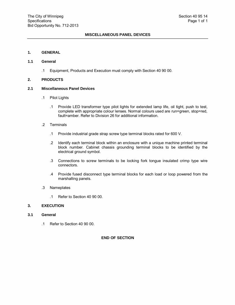
The City of Winnipeg Section 40 95 14 Specifications Page 1 of 1 Bid Opportunity No. 712-2013
MISCELLANEOUS PANEL DEVICES
1. GENERAL
1.1 General
.1 Equipment, Products and Execution must comply with Section 40 90 00.
2. PRODUCTS
2.1 Miscellaneous Panel Devices
.1 Pilot Lights
.1 Provide LED transformer type pilot lights for extended lamp life, oil tight, push to test, complete with appropriate colour lenses. Normal colours used are run=green, stop=red, fault=amber. Refer to Division 26 for additional information.
.2 Terminals
.1 Provide industrial grade strap screw type terminal blocks rated for 600 V.
.2 Identify each terminal block within an enclosure with a unique machine printed terminal block number. Cabinet chassis grounding terminal blocks to be identified by the electrical ground symbol.
.3 Connections to screw terminals to be locking fork tongue insulated crimp type wire connectors.
.4 Provide fused disconnect type terminal blocks for each load or loop powered from the marshalling panels.
.3 Nameplates
.1 Refer to Section 40 90 00.
3. EXECUTION
3.1 General
.1 Refer to Section 40 90 00.
END OF SECTION

The City of Winnipeg Section 40 95 53 Specifications Page 1 of 2 Bid Opportunity No. 712-2013
SWITCHES AND RELAYS
1. GENERAL
1.1 General
.1 Refer to Section 40 90 00.
1.2 References
.1 American National Standards Institute (ANSI)/National Electrical Manufacturers Association (NEMA)
.1 NEMA 250, Enclosures for Electrical Equipment (1000 Volts Maximum).
.2 ANSI/NEMA ICS 2, Industrial Control and Systems: Controllers, Contactors, and Overload Relays, Rated 600 Volts.
.3 NEMA ICS 6, Industrial Control and Systems: Enclosures
2. PRODUCTS
2.1 General
.1 Use normally closed contacts for alarm actuation. The contacts open to initiate the alarm.
.2 Use normally open contacts to control equipment. The contacts close to start the equipment.
.3 Contacts monitored by solid state equipment to be hermetically sealed and adequately rated for the connected load.
.4 Contacts monitored by electro-magnetic devices such as mechanical relays to be rated ANSI/NEMA ICS 2, designation B300.
.5 Provide double barriers between switch elements and process fluids such that failure of one barrier will not permit process fluids into electrical enclosures.
.6 Switch electrical enclosures to be rated NEMA 4X, minimum.
.7 120 VAC switches to have a minimum of a 4 A rating.
2.2 Indicators, Pushbuttons and Selector Switches
.1 All control indicator lamps, pushbutton switches, and selector switches in ordinary locations to be heavy duty oil tight such as Allen Bradley 800T or 800E or equivalent in accordance with B8.
.2 All control indicator lamps, pushbutton switches, and selector switches in classified or Category 1 & 2 areas, or outdoors to be heavy duty weatherproof such as Allen Bradley 800H or equivalent in accordance with B8.
.3 All control indicator lamps shall be push-to-test type.

The City of Winnipeg Section 40 95 53 Specifications Page 2 of 2 Bid Opportunity No. 712-2013
SWITCHES AND RELAYS
2.3 Relays
.1 The Quality and type of relays shall be based on industrial grade types generally as described below with contact rated for connected loads.
.2 120 VAC relays to be 4PDT, plug-in, complete with test button and operation indicator, and surge suppressor.
.3 24 VDC relays to be 2PDT plug-in, complete with test button and operation indicator, and surge suppressor diode.
.4 Time delay relays for behind panel mounting to be Model 2PDT, plug-in, and programmable for sixteen (16) time ranges and four (4) operation modes.
.5 Time delay relays for flush panel mounting and operator accessible timing range modifications to be SPDT, screw terminals, programmable for five (5) timing ranges and eight (8) operation modes, complete with digital display, module for time settings and flexible protective cover.
.6 Where the contact ratings of the relays listed are insufficient for the application select an appropriate type from an approved manufacturer with the same quantity of contacts as was originally specified.
.7 Provide relay plug-in sockets for DIN mounting complete with stacked screw clamp terminals.
2.4 Process Switches
.1 Standard of acceptance for instrumentation shall be as follows:
.1 Float Switches shall be SPDT types with moulded polypropylene casing and pre-terminated and sealed corrosion extension cable.
3. EXECUTION
3.1 General
.1 Refer to Section 40 90 00.
END OF SECTION

The City of Winnipeg Section 40 95 56 Specifications Page 1 of 2 Bid Opportunity No. 712-2013
POWER SUPPLIES
1. GENERAL
1.1 General
.1 Refer to Section 40 90 00 - Common Work - Instrumentation and Controls.
1.2 References
.1 Underwriters Laboratories Inc. (UL):
.1 UL 1449, Standard for Safety Surge Protective Devices.
2. PRODUCTS
2.1 Power Supply and Conditioning Equipment
.1 General
.1 Provide all DC power supplies as required for all instrument circuits. All instrument circuits are t o be powered f rom the marshalling panel s. Power supplies shall be dual redundant types with automatic fail-over function, fault contacts, and over-voltage protection module.
.2 DC power suppl ies shall be fully redundant w ith both unit s being rated for the connected load. Individual fault signals f rom each power supply shal l be monitored by the PLC for alarming.
.3 Unless otherwise required, all DC power supplies to be rated 28 VDC, adjustable plus or minus 5%, and set to provide 24.0 V on the panel direct current bus. Size the power supply for two (2) times the connected load, minimum size is 2 amps.
2.2 Noise Suppression
.1 Provide Surge Protective Devices (SPD) in each panel to power AC instrumentation and control (I&C) loads. Power conditioners constructed in accordance with UL 1449 are to be provided.
2.3 Control Panel Power Supply
.1 Two (2) sources of 120 VAC power w ill be supplied to each control panel: one circuit will feed the UPS unit for critical loads and a second circuit will feed non-critical loads.
.2 Control and operator interface system hardware including but not limited to programmable logic controllers (PLCs), PLC I/O racks, PLC communication m odules, displays, and industrial network switches shall be powered from the UPS.
.3 Instrument power and associated DC power supplies shall be powered from the UPS.
.4 Non-critical loads include control panel interior lights and receptacles.

The City of Winnipeg Section 40 95 56 Specifications Page 2 of 2 Bid Opportunity No. 712-2013
POWER SUPPLIES
.5 Provide the total expected critical and non-critical loads fed from each control panel as a Shop Drawing submittal so that the external power sources and UPS can be properly sized.
2.4 Noise Suppression
.1 Provide power conditioners in each panel to power AC instrumentation and control loads. Power conditioners are Oneac Series CX or acceptable alternative.
2.5 UPS Power Supply
.1 Provide an un-interruptible power supply (UPS) in each control panel to power control system and SCADA equipment.
.2 Size UPS standby capacity for 30 minutes at full load rating.
.3 Provide on-line units from Exide, Oneac, Toshiba, Best or approved equal in accordance with
B8.
3. EXECUTION
3.1 General
.1 Refer to Section 40 90 00 - Common Work - Instrumentation and Controls.
END OF SECTION

The City of Winnipeg Section 40 95 73 Specifications Page 1 of 4 Bid Opportunity No. 712-2013
INSTRUMENTATION CABLE
1. GENERAL
1.1 Related Work
.1 Refer to Division 26.
1.2 Product Data
.1 Submit product data in accordance with Division 26.
1.3 Inspection
.1 Provide adequate notice to the Contract Administrator so that all cable installations can be inspected prior to energizing equipment.
1.4 Standards
.1 All wire and cable shall be CSA Certified.
2. PRODUCTS
2.1 Twisted Pair Shielded Cables (TPSH)
.1 TPSH shall be constructed as follows:
.1 Two (2) copper conductors, stranded, minimum #18 AWG, PVC insulated, twisted in nominal intervals of 50 mm.
.2 Insulated for 600 V, 90°C
.3 100 percent coverage aluminum foil or tape shield.
.4 Separate bare stranded copper drain wire, minimum #18 AWG.
.5 Overall flame retardant PVC jacket to CSA-C22.2.
.6 The entire cable assembly to be suitable for pulling in conduit or laying in cable tray.
.7 Interlocked aluminum armour and outer PVC jacket.
.8 Shaw Type 1751-CSA or equivalent as approved in accordance with B8.
.2 Where multi-conductor TPSH cables are called for, each pair shall be individually shielded, continuous number coded, and the cable assembly shal l have an ov erall shield and ov erall flame retardant PVC jacket.
2.2 RTD and Multi Conductor Shielded Cable
.1 RTD cables shall be CSA approved and shall be constructed as follows:

The City of Winnipeg Section 40 95 73 Specifications Page 2 of 4 Bid Opportunity No. 712-2013
INSTRUMENTATION CABLE
.1 Three or more copper conductors, stranded, minimum # 18 AWG.
.2 PVC insulated for 600 V.
.3 100 percent coverage aluminum foil or tape shield.
.4 Separate bare stranded copper drain wire.
.5 Interlocked aluminum armour and outer PVC jacket.
.6 Overall flame retardant PVC jacket to CSA-C22.2.
2.3 TECK Cables
.1 As per Division 26.
2.4 Wire
.1 As per Division 26.
2.5 100 Base TX Category 5e Communication Cable
.1 Category 5E cable shall be CSA Certified and constructed as follows:
.1 4 bonded pairs, solid stranded, #24 AWG.
.2 Interlocked aluminum armour.
.3 Rip cord.
.4 PVC inner and outer jackets.
.5 UL verified to Category 5E.
.6 Insulated for 300 V.
.7 Belden 121700A or equivalent as approved in accordance with B8.
3. EXECUTION
3.1 General
.1 Refer to Section 40 90 00.
3.2 Analog Signals
.1 Use TPSH cable for all low level analog signals such as 4-20 mA, pulse type circuits 24 VDC and under, and other signals of a similar nature.
.2 Use RTD cable for connections between RTDs and transmitters or control s ystem RTD inputs.

The City of Winnipeg Section 40 95 73 Specifications Page 3 of 4 Bid Opportunity No. 712-2013
INSTRUMENTATION CABLE
3.3 Digital Signals
.1 Use TPSH cable for all low level input (24 V and below) and output signals to the control system.
3.4 Instrument Power
.1 Use TECK cable or wire and conduit for power to instruments, for 120 V signals other than those mentioned above and as otherwise indicated on the Drawings. Use stranded wire and cable to supply power to instruments.
3.5 Installation
.1 Install instrumentation cables in conduit systems or i n cable trays. Use a m inimum o f 300 mm and a maximum of 1000 mm length of liquid tight flexible conduit to connect the field sensors to the conduit.
.2 Where non-armoured instrumentation cables are installed in cable trays, provide barriers in the tray to separate instrumentation cables from power cables.
.3 At each end of the run leave sufficient cable length for termination.
.4 Do not make splices in any of the instrumentation cable runs.
.5 Cable shields shall be terminated on insulated terminals and carried through to the extent of the cable.
.6 Ground cable shields at one end only. Unless otherwise specified, ground the shields at the marshalling panel.
.7 Protect all conductors against moisture during and after installation.
3.6 Cat 5E Installation:
.1 Always follow the Manufacturer's guidelines for minimum bend radius and tension.
.2 All installations and terminations shall be performed by personnel experienced in Cat 5E cable installation.
.3 Perform cable testing with time domain reflectometer (T DR) i nstrument and provide complete detailed test report. T est all runs upon completion of permanent terminations, using instrumentation acceptable to the Contract Administrator. Before commencing testing, submit sam ple t est data sheets and i nformation wi th respect to t est i nstrumentation to be used.
.1 Test for the following:
.1 Continuity.
.2 Pair placement and polarity.

The City of Winnipeg Section 40 95 73 Specifications Page 4 of 4 Bid Opportunity No. 712-2013
INSTRUMENTATION CABLE
.3 DC resistance.
.4 Characteristics at highest contemplated frequency:
.1 Attenuation - data cable.
.2 Mutual Capacitance - data cable.
.3 Near-end crosstalk (NEXT) - data cable.
.5 Run length.
.2 Tests to be conducted to Cat 5E standards
.3 Reconnect or re-install and retest as necessary to correct excessive variations.
3.7 Conductor Terminations
.1 All equipment suppli ed s hall be equi pped w ith te rminal bl ocks to accept c onductor connections.
.2 Instrumentation conductors, where terminated at equipment terminals other than clamping type terminal blocks, shall be equipped with self-insulated, locking type terminators, sized as required to fit conductors and screw terminals.
3.8 Testing
.1 Test all conductors for opens, shorts, or grounds. Resistance values shall not be less than those recommended by the cable manufacturer.
3.9 Identification
.1 Identify all instrumentation cables.
.2 Identify each conductor with wire numbers using a machine printed heat-shrink wire marker.
END OF SECTION

The City of Winnipeg Section 40 96 05 Specifications Page 1 of 5 Bid Opportunity No. 712-2013
INSTRUMENTATION SPECIFICATION SHEETS
1. GENERAL
1.1 General
.1 The Work includes the provision of i nstrument s pecification sheets for all instr uments supplied for this project.
.2 Refer to Section 40 90 00 for instrumentation and contr ol co mmon work related to the instrument specification sheets.
1.2 References
.1 International Society of Automation (ISA):
.1 ISA 20, Specif ication Forms for P rocess Measurement and Control I nstruments, Primary Elements and Control Valves.
.2 National Electrical Manufacturers Association (NEMA)
.1 NEMA 250, Enclosures for Electrical Equipment (1000 Volts Maximum).
.2 NEMA ICS 6, Industrial Control and Systems: Enclosures.
1.3 Instrument Specification Sheets
.1 Provide data sheets to itemize detailed as-built information regarding the Specification of instruments i ncluded as part of this Work f or each instrument supplied. The dat a sheet s already included in this Section list specific minimum requirements for particular applications.
.2 Use forms in accordance with the ISA 20 as a template for the preparation of the specification sheets.
2. PRODUCTS
.1 Refer to the following specification sheets.
3. EXECUTION (NOT USED)

The City of Winnipeg Section 40 96 05 Specifications Page 2 of 5 Bid Opportunity No. 712-2013
INSTRUMENTATION SPECIFICATION SHEETS
INSTRUMENT SPECIFICATION NUMBER: I-101
DEVICE:
Liquid Level Transmitter
TAG:
Refer to Instrument Index, Section 40 96 20
TYPE:
Ultrasonic
SERVICE:
Refer to Instrument Index and P&ID Diagrams
RANGE:
Refer to Instrument Index, Section 40 96 20
INACCURACY:
0.5% of span
OUTPUT:
4 to 20 mA DC into 500 ohm load 5 configurable alarm relays
POWER SUPPLY:
120 VAC, 60 HZ
ENCLOSURE:
NEMA 4X Transmitter Housing NEMA 4X Sensor with Class 1, Zone 1 Rating
MOUNTING: (TRANSMITTER)
(SENSOR)
Wall Mount Provide PVC pipe mounting well with flange and mount sensor in accordance with manufacturer’s recommendations to ensure stable readings. Mounting well shall extend 150 mm AFF. Install sensors at least 350 mm above maximum liquid level. Provide PVC blind flange for mounting sensor.
ACCESSORIES:
1 - hand-held programmer
MANUFACTURER:
Siemens Magnetrol Endress & Hauser

The City of Winnipeg Section 40 96 05 Specifications Page 3 of 5 Bid Opportunity No. 712-2013
INSTRUMENTATION SPECIFICATION SHEETS
INSTRUMENT SPECIFICATION NUMBER: I-102
DEVICE: Float Switch
TAG: Refer to Instrument Index, Section 40 96 20
SERVICE: Refer to Instrument Index and P&ID Diagrams
OUTPUT: SPDT Contacts
ENCLOSURE: NEMA 4X Polypropylene float casing with pre-terminated signal cable and Class 1, Zone 1 rating.
MOUNTING: Locate the float switch near an access hatch and away from turbulent areas of the vessel if possible. Provide strain relief-type connectors to suspend float at desired location. Fabricate mounting brackets from 316 SS. Provide anti-sway rings to prevent tangling of the float cable.
MANUFACTURER: Flygt (Xylem Inc.) Consolidated Electric Cooperative Inc. Warwick (Gems Sensors & Controls) Magnetrol
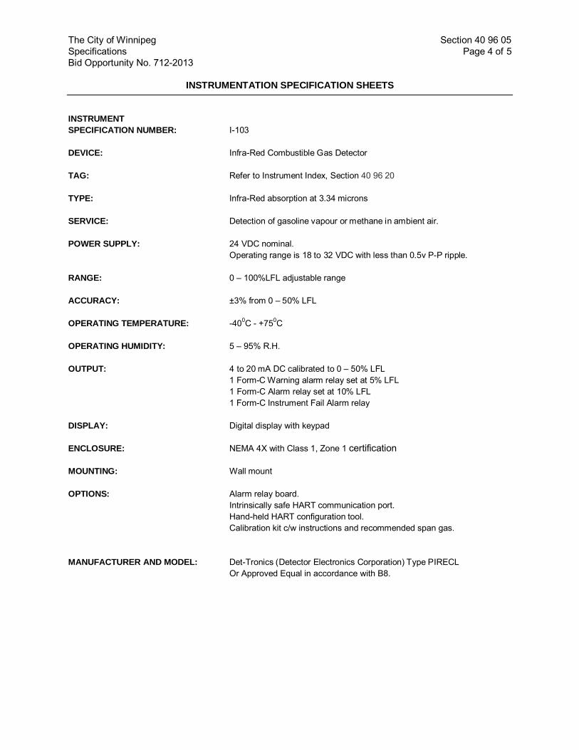
The City of Winnipeg Section 40 96 05 Specifications Page 4 of 5 Bid Opportunity No. 712-2013
INSTRUMENTATION SPECIFICATION SHEETS
INSTRUMENT SPECIFICATION NUMBER:
I-103
DEVICE:
Infra-Red Combustible Gas Detector
TAG:
Refer to Instrument Index, Section 40 96 20
TYPE: Infra-Red absorption at 3.34 microns
SERVICE:
Detection of gasoline vapour or methane in ambient air.
POWER SUPPLY: 24 VDC nominal. Operating range is 18 to 32 VDC with less than 0.5v P-P ripple.
RANGE:
0 – 100%LFL adjustable range
ACCURACY: ±3% from 0 – 50% LFL
OPERATING TEMPERATURE:
-400C - +750C
OPERATING HUMIDITY:
5 – 95% R.H.
OUTPUT:
4 to 20 mA DC calibrated to 0 – 50% LFL 1 Form-C Warning alarm relay set at 5% LFL 1 Form-C Alarm relay set at 10% LFL 1 Form-C Instrument Fail Alarm relay
DISPLAY:
Digital display with keypad
ENCLOSURE:
NEMA 4X with Class 1, Zone 1 certification
MOUNTING:
Wall mount
OPTIONS: Alarm relay board. Intrinsically safe HART communication port. Hand-held HART configuration tool. Calibration kit c/w instructions and recommended span gas.
MANUFACTURER AND MODEL:
Det-Tronics (Detector Electronics Corporation) Type PIRECL Or Approved Equal in accordance with B8.

The City of Winnipeg Section 40 96 05 Specifications Page 5 of 5 Bid Opportunity No. 712-2013
INSTRUMENTATION SPECIFICATION SHEETS
INSTRUMENT SPECIFICATION NUMBER:
I-104
DEVICE:
Combustible Gas Alarms
PANEL TAG:
AA-100
PANEL LABEL:
Lamicoid: “PANEL AA-100”
“Combustible Gas Warning”
SERVICE:
Duty Pump Wet Well.
ENCLOSURE: NEMA 12 Wall mounted cabinet.
POWER SUPPLY: 120 VAC
OPERATING TEMPERATURE:
-400C - +400C
OPERATING HUMIDITY:
5 – 95% R.H.
STROBE LIGHT:
Edwards Signaling or Federal Signal Corporation strobe light with Red lens.
BUZZER:
Edwards Signaling or Federal Signal Corporation alarm buzzer.
SILENCE BUTTON:
Refer to 40 95 53 Provide Lamicoid label: “Silence”
SILENCE RELAY:
Refer to 40 95 53
END OF SECTION

The City of Winnipeg Section 40 96 10 Specifications Page 1 of 1 Bid Opportunity No. 712-2013
INSTRUMENT LOOP DRAWINGS
1. GENERAL
1.1 General
.1 Refer to Section 40 90 00.
1.2 Instrument Loop Drawings
.1 The following Drawings show typical i nstrument loop and motor control w iring diagrams. One (1) drawing per loop or motor dr ive will be completed by the Contractor and submitted for approval after award of Contract. The Contractor must review each wiring detail together with t he r eviewed sho p dr awings f or the r espective equipm ent and m odify the dr awing t o comply with the selected equipment manufacturer’s requirements. Record al l modifications, terminal numbers, wire numbers, etc. to as-constructed stat us and i nclude copies of each drawing in the as-constructed drawing set.The following drawings are an integral part of this Specification Section:
ILD-01 Instrument Loop Diagram – FVNR Soft Starter ILD-02 Instrument Loop Diagram – Submersible Motor Protection Relays ILD-03 Instrument Loop Diagram – Thermistor Relay Connection ILD-04 Instrument Loop Diagram – Typical Ultrasonic Level Transmitter ILD-05 Instrument Loop Diagram – Typical High Level Switch ILD-06 Instrument Loop Diagram – Combustible Gas Detector ILD-07 Instrument Loop Diagram – General Alarms ILD-08 Instrument Loop Diagram – Door/Window Magnetic Switch
2. PRODUCTS (NOT USED)
3. EXECUTION (NOT USED)
END OF SECTION

FVNR Starter - Instrument Loop Diagram Loop No. XXXX
MCC AREA FIELD PROCESS AREA CONTROL PANEL
CO
H
X00
X00
00X
HS
XXXX
COH
XXXX-3A
XXXX-1A
XXXX-3A
XXXX-1A MN-XXXXDISCRETE OUTPUTSTART/STOP COMMAND
XXXX-19
XXXX-X2 YS-XXXXDISCRETE INPUTCOMPUTER SELECTEDXXXX-19
XXXX-X2XXXX-X2
XXXX-1O/L's
XXXX-X1
MM-XXXXR
M
MO-XXXXG
XXXX-3
Ma
Ma
XXXX-14
XXXX-16
XXXX-1
XXXX-14
XXXX-1
XXXX-16
Ma
O/L
XXXX-14
XXXX-16
XXXX-X2
XXXX-X2
MM-XXXXDISCRETE INPUTRUNNING STATUS
UA-XXXXDISCRETE INPUTFAULT
6C #14 TECK CABLE
PLCX2 X1120 VAC
XXXX-3A
FIELDINTERLOCKS(NOTE 2)
SHEET TITLE
SHEET NUMBER
Last
sav
ed b
y: G
ALB
ICH
KAS
(201
3-09
-16
)
Last
Plo
tted:
201
3-10
-16
AAA
BBB
CC
CFi
lena
me:
P:\6
0273
041\
000-
CA
DD
\02-
SH
EE
TS\I\
CO
NTR
AC
T 3\
6027
3041
-SH
T-01
-CO
N3-
I-000
0.D
WG
ISSUE/REVISION
I/R DATE DESCRIPTION
PROJECT
PLESSIS ROAD TWINNING &GRADE SEPARATION ATCN REDDITT SUBDIVISION
CONTRACT 3
CONSULTANT
AECOM Canada, Ltd.99 Commerce DriveWinnipeg, Manitoba R3P 0Y7204.477.5381 tel 204.284.2040 faxwww.aecom.com
NOTES
INSTRUMENT LOOP DIAGRAMTYPICAL FVNR STARTER
ILD-001
0 2013/10/15 ISSUED FOR TENDER
1. THIS DRAWING IS TYPICAL FOR SEVERAL DRIVES. REFER TOINSTRUMENT INDEX FOR APPLICATIONS.
2. REFER TO OTHER LOOP DIAGRAMS FOR FIELD INTERLOCKREQUIREMENTS.
3. FIELD WIRING SUITABLE FOR CLASS 1, ZONE 1 AREA.

Submersible Motor Protection Relay - Instrument Loop Diagram Loop No. XXXX
FIELD PROCESS AREA CONTROL PANEL
PLC
MOTOR STARTER
+
-
MOISTUREPROBE
TO SUBMERSIBLEPUMP / MIXER
L1
N
G
MOISTUREALARM
L1
N
G
TEMPERATUREALARM
120 VAC, 60 HzPOWER SUPPLY
120 VAC, 60 HzPOWER SUPPLY
XXXX-22
XXXX-21
XXXX-23
XXXX-24
XXXX-25
FIELD INTERLOCK(NOTE 2)
XXXX-22
XXXX-21
XXXX-23
XXXX-24
XXXX-25
L1 N1120 VAC
R1
R2
R1
XXXX-N
XXXX-30
NAH-XXXXDISCRETE INPUTMOISTURE ALARM
R2
XXXX-N
XXXX-31
TAH-XXXXDISCRETE INPUTHIGH TEMPERATURE ALARM
R1
R2
THERMAL PROTECTION RELAY
MOISTURE PROTECTION RELAY
+
-
TEMPERATUREPROBE
SHEET TITLE
SHEET NUMBER
Last
sav
ed b
y: G
ALB
ICH
KAS
(201
3-09
-16
)
Last
Plo
tted:
201
3-10
-16
AAA
BBB
CC
CFi
lena
me:
P:\6
0273
041\
000-
CA
DD
\02-
SH
EE
TS\I\
CO
NTR
AC
T 3\
6027
3041
-SH
T-01
-CO
N3-
I-000
0.D
WG
ISSUE/REVISION
I/R DATE DESCRIPTION
PROJECT
PLESSIS ROAD TWINNING &GRADE SEPARATION ATCN REDDITT SUBDIVISION
CONTRACT 3
CONSULTANT
AECOM Canada, Ltd.99 Commerce DriveWinnipeg, Manitoba R3P 0Y7204.477.5381 tel 204.284.2040 faxwww.aecom.com
NOTES
INSTRUMENT LOOP DIAGRAMSUBMERSIBLE MOTORPROTECTION RELAY
ILD-002
0 2013/10/15 ISSUED FOR TENDER
1. THIS DRAWING IS TYPICAL FOR SEVERAL DRIVES. REFER TOINSTRUMENT INDEX FOR APPLICATIONS.
2. REFER TO OTHER LOOP DIAGRAMS FOR CONNECTION TOMOTOR STARTING CIRCUITS.
3. FIELD WIRING SUITABLE FOR CLASS 1, ZONE 1 AREA OR USEINTRINSICALLY SAFE BARRIERS.

Thermistor Relay Connection - Instrument Loop Diagram Loop No. XXXX
MOTOR TERMINAL BOX CONTROL PANEL
PLC
MOTOR STARTER OR VFD
A1
A2
XXXX-L1
XXXX-14 XXXX-14
XXXX-N
TH-XXXXDISCRETE INPUTMOTOR HIGH TEMPERATURE
L1 N1120 VAC
L1 N1120 VAC
21
22
13
14
FIELD INTERLOCK(NOTE 2)
T1
T2
XXXX-13
XXXX-13
WINDING APTC
WINDING BPTC
WINDING CPTC
PTC THERMISTOR RELAY(ABB #CM-MSS-2 OR APPROVED EQUAL)
SHEET TITLE
SHEET NUMBER
Last
sav
ed b
y: G
ALB
ICH
KAS
(201
3-09
-16
)
Last
Plo
tted:
201
3-10
-16
AAA
BBB
CC
CFi
lena
me:
P:\6
0273
041\
000-
CA
DD
\02-
SH
EE
TS\I\
CO
NTR
AC
T 3\
6027
3041
-SH
T-01
-CO
N3-
I-000
0.D
WG
ISSUE/REVISION
I/R DATE DESCRIPTION
PROJECT
PLESSIS ROAD TWINNING &GRADE SEPARATION ATCN REDDITT SUBDIVISION
CONTRACT 3
CONSULTANT
AECOM Canada, Ltd.99 Commerce DriveWinnipeg, Manitoba R3P 0Y7204.477.5381 tel 204.284.2040 faxwww.aecom.com
NOTES
INSTRUMENT LOOP DIAGRAMTHERMISTOR RELAY CONNECTION
ILD-003
0 2013/10/15 ISSUED FOR TENDER
1. THIS DRAWING IS TYPICAL FOR SEVERAL DRIVES. REFER TOINSTRUMENT INDEX FOR APPLICATIONS.
2. REFER TO OTHER LOOP DIAGRAMS FOR CONNECTION TOMOTOR STARTING CIRCUITS.
3. FIELD WIRING SUITABLE FOR CLASS 1, ZONE 1 AREA OR USEINTRINSICALLY SAFE BARRIERS.

Ultrasonic Level Transmitter - Instrument Loop Diagram Loop No. XXXX
PLC
FIELD PROCESS AREA CONTROL PANEL
LEVEL TRANSMITTER
+
-
4-20 mAOUTPUT XXXX-72
XXXX-71
XXXX-S
XXXX-XX
L
N
G
120 VAC, 60 HzPOWER SUPPLY
XXXX-XX
LI-XXXXANALOG INPUTLEVEL
RELAY OUTPUT FAULT XXXX-XX
XXXX-XX
L1 N1120 VAC
XXXX-XX
LF-XXXXDISCRETE INPUTLOSS OF ECHO FAILURE
XXXX-XX
XXXX-XX
CB
LIT
XXXX
LE
XXXX
TRANSDUCERCABLE IN RIGID PVCCONDUIT SUPPLIEDBY CONTRACTOR
SHEET TITLE
SHEET NUMBER
Last
sav
ed b
y: D
ENO
UD
ENW
(201
3-10
-16
)
Last
Plo
tted:
201
3-10
-16
AAA
BBB
CC
CFi
lena
me:
P:\6
0273
041\
000-
CA
DD
\02-
SH
EE
TS\I\
CO
NTR
AC
T 3\
6027
3041
-SH
T-01
-CO
N3-
I-000
0.D
WG
ISSUE/REVISION
I/R DATE DESCRIPTION
PROJECT
PLESSIS ROAD TWINNING &GRADE SEPARATION ATCN REDDITT SUBDIVISION
CONTRACT 3
CONSULTANT
AECOM Canada, Ltd.99 Commerce DriveWinnipeg, Manitoba R3P 0Y7204.477.5381 tel 204.284.2040 faxwww.aecom.com
NOTES
INSTRUMENT LOOP DIAGRAMTYPICAL ULTRASONICLEVEL TRANSMITTER
ILD-004
0 2013/10/15 ISSUED FOR TENDER
1. THIS DRAWING IS TYPICAL FOR SEVERAL INSTRUMENTS. REFERTO INSTRUMENT INDEX FOR APPLICATIONS.
3. FIELD WIRING SUITABLE FOR CLASS 1, ZONE 1 AREA OR USEINTRINSICALLY SAFE BARRIERS FOR OUTPUTS.

High Level Float Switch - Instrument Loop Diagram Loop No. XXXX
PLC
XXXX-25
XXXX-H
XXXX-25
XXXX-N
LH-XXXXDISCRETE INPUTHIGH LEVEL
FIELD PROCESS AREA CONTROL PANEL
H N120 VAC
PROCESS STATUS SWITCH
LSH
XXXX
APPLICATION:HIGH LEVEL FLOAT SWITCH
SHEET TITLE
SHEET NUMBER
Last
sav
ed b
y: G
ALB
ICH
KAS
(201
3-09
-16
)
Last
Plo
tted:
201
3-10
-16
AAA
BBB
CC
CFi
lena
me:
P:\6
0273
041\
000-
CA
DD
\02-
SH
EE
TS\I\
CO
NTR
AC
T 3\
6027
3041
-SH
T-01
-CO
N3-
I-000
0.D
WG
ISSUE/REVISION
I/R DATE DESCRIPTION
PROJECT
PLESSIS ROAD TWINNING &GRADE SEPARATION ATCN REDDITT SUBDIVISION
CONTRACT 3
CONSULTANT
AECOM Canada, Ltd.99 Commerce DriveWinnipeg, Manitoba R3P 0Y7204.477.5381 tel 204.284.2040 faxwww.aecom.com
NOTES
INSTRUMENT LOOP DIAGRAMTYPICAL HIGH LEVEL SWITCH
ILD-005
0 2013/10/15 ISSUED FOR TENDER
1. THIS DRAWING IS TYPICAL FOR SEVERAL INSTRUMENTS. REFERTO INSTRUMENT INDEX FOR APPLICATIONS.
2. FIELD WIRING SUITABLE FOR CLASS 1, ZONE 1 AREA.
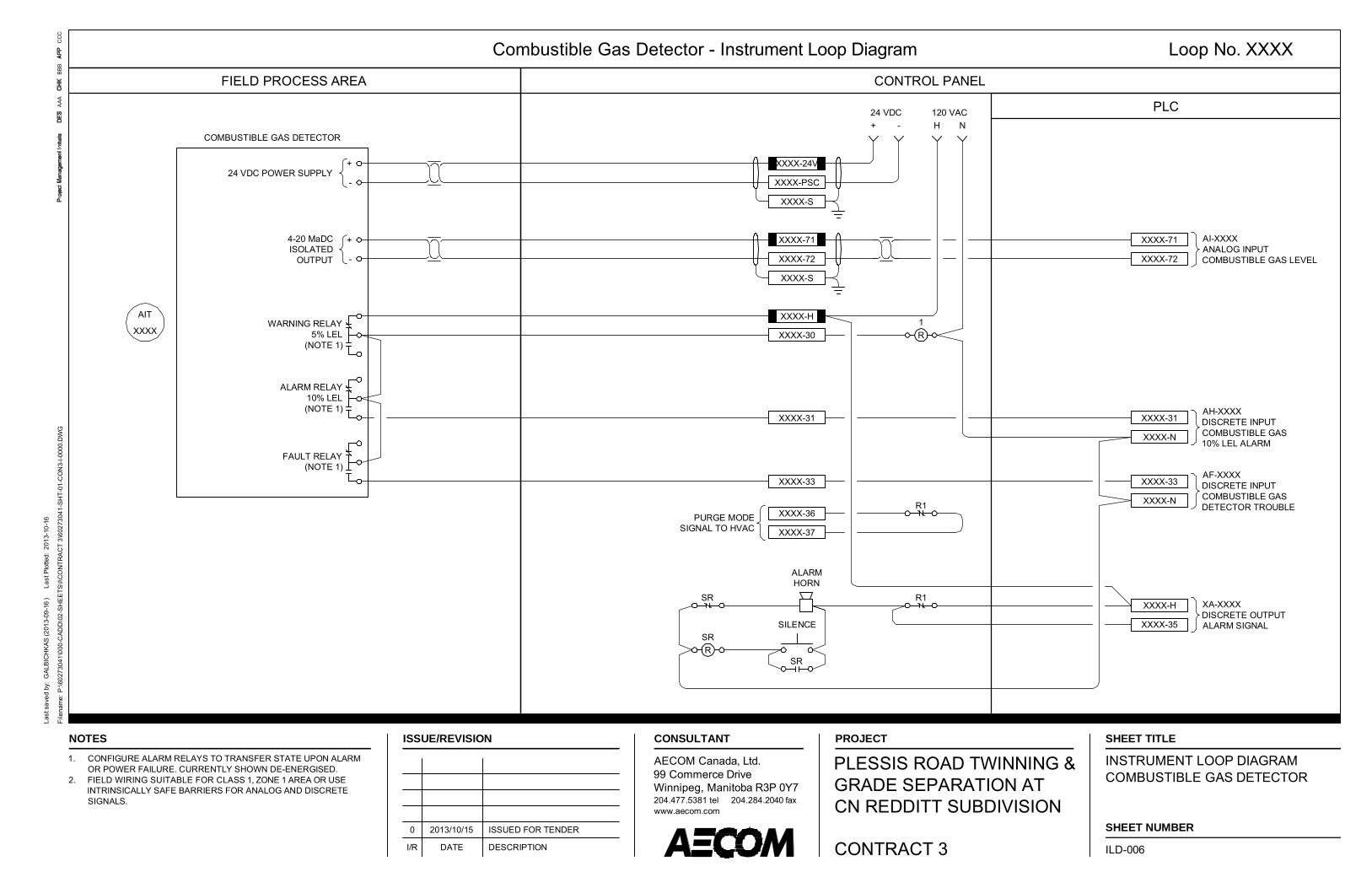
Combustible Gas Detector - Instrument Loop Diagram Loop No. XXXX
PLC
FIELD PROCESS AREA CONTROL PANEL
COMBUSTIBLE GAS DETECTOR
XXXX-PSC
XXXX-S
+
-24 VDC POWER SUPPLY
+
-
4-20 MaDC ISOLATED
OUTPUT
WARNING RELAY5% LEL
(NOTE 1)
ALARM RELAY10% LEL(NOTE 1)
FAULT RELAY(NOTE 1)
AIT
XXXX
XXXX-24V
+ -24 VDC
H N120 VAC
XXXX-72
XXXX-S
XXXX-71 AI-XXXXANALOG INPUTCOMBUSTIBLE GAS LEVEL
XXXX-71
XXXX-72
XXXX-30
XXXX-H
R1
AF-XXXXDISCRETE INPUTCOMBUSTIBLE GASDETECTOR TROUBLE
XXXX-33
XXXX-N
AH-XXXXDISCRETE INPUTCOMBUSTIBLE GAS10% LEL ALARM
XXXX-31
XXXX-N
XXXX-31
XXXX-33
SR
RSR
SILENCE
SR
R1
R1
XXXX-37
XXXX-36PURGE MODESIGNAL TO HVAC
ALARMHORN
XA-XXXXDISCRETE OUTPUTALARM SIGNAL
XXXX-H
XXXX-35
SHEET TITLE
SHEET NUMBER
Last
sav
ed b
y: G
ALB
ICH
KAS
(201
3-09
-16
)
Last
Plo
tted:
201
3-10
-16
AAA
BBB
CC
CFi
lena
me:
P:\6
0273
041\
000-
CA
DD
\02-
SH
EE
TS\I\
CO
NTR
AC
T 3\
6027
3041
-SH
T-01
-CO
N3-
I-000
0.D
WG
ISSUE/REVISION
I/R DATE DESCRIPTION
PROJECT
PLESSIS ROAD TWINNING &GRADE SEPARATION ATCN REDDITT SUBDIVISION
CONTRACT 3
CONSULTANT
AECOM Canada, Ltd.99 Commerce DriveWinnipeg, Manitoba R3P 0Y7204.477.5381 tel 204.284.2040 faxwww.aecom.com
NOTES
INSTRUMENT LOOP DIAGRAMCOMBUSTIBLE GAS DETECTOR
ILD-006
0 2013/10/15 ISSUED FOR TENDER
1. CONFIGURE ALARM RELAYS TO TRANSFER STATE UPON ALARMOR POWER FAILURE. CURRENTLY SHOWN DE-ENERGISED.
2. FIELD WIRING SUITABLE FOR CLASS 1, ZONE 1 AREA OR USEINTRINSICALLY SAFE BARRIERS FOR ANALOG AND DISCRETESIGNALS.

General Alarm - Instrument Loop Diagram Loop No. XXXX
PLC
FIELD PROCESS AREA CONTROL PANEL
XXXX-24 +
XXXX-S
L1 N120 VAC
XXXX-XX
SOLID STATE RELAY(NOTE 1)
XXXX-XX
XXXX-XX
ZB-XXXXDISCRETE INPUTDOOR POSITION
ZSB
XXXX
+ -24 VDC
INTRINSICALLYSAFE BARRIER
(NOTE 2)
SHEET TITLE
SHEET NUMBER
Last
sav
ed b
y: G
ALB
ICH
KAS
(201
3-09
-16
)
Last
Plo
tted:
201
3-10
-16
AAA
BBB
CC
CFi
lena
me:
P:\6
0273
041\
000-
CA
DD
\02-
SH
EE
TS\I\
CO
NTR
AC
T 3\
6027
3041
-SH
T-01
-CO
N3-
I-000
0.D
WG
ISSUE/REVISION
I/R DATE DESCRIPTION
PROJECT
PLESSIS ROAD TWINNING &GRADE SEPARATION ATCN REDDITT SUBDIVISION
CONTRACT 3
CONSULTANT
AECOM Canada, Ltd.99 Commerce DriveWinnipeg, Manitoba R3P 0Y7204.477.5381 tel 204.284.2040 faxwww.aecom.com
NOTES
INSTRUMENT LOOP DIAGRAMDOOR / WINDOW MAGNETIC SWITCH
ILD-007
0 2013/10/15 ISSUED FOR TENDER
1. PROVIDE INTERPOSING RELAY TO FACILITATE INTERFACING THELOW VOLTAGE DOOR CONTACT WITH THE 120 VAC PLC INPUT.
2. SUPPLY AND INSTALL INTRINSICALLY SAFE BARRIER.

Two Wire Transmitter - Instrument Loop Diagram Loop No. XXXX
PLC
FIELD PROCESS AREA CONTROL PANEL
TWO WIRE PROCESS TRANSMITTER
XXXX-71
XXXX-72
XXXX-S
+
-
420 MaOUTPUT
TT-XXXXANALOG INPUT4-20 MaDC
1 PR #18 TPSH
+ -24 VDC
APPLICATION:TEMPERATURE INDICATINGTRANSMITTER
INTRINSICALLYSAFE BARRIER
(NOTE 3)
XXXX-71+
XXXX-72-
1 PR #18 TPSH
SHEET TITLE
SHEET NUMBER
Last
sav
ed b
y: G
ALB
ICH
KAS
(201
3-09
-16
)
Last
Plo
tted:
201
3-10
-16
AAA
BBB
CC
CFi
lena
me:
P:\6
0273
041\
000-
CA
DD
\02-
SH
EE
TS\I\
CO
NTR
AC
T 3\
6027
3041
-SH
T-01
-CO
N3-
I-000
0.D
WG
ISSUE/REVISION
I/R DATE DESCRIPTION
PROJECT
PLESSIS ROAD TWINNING &GRADE SEPARATION ATCN REDDITT SUBDIVISION
CONTRACT 3
CONSULTANT
AECOM Canada, Ltd.99 Commerce DriveWinnipeg, Manitoba R3P 0Y7204.477.5381 tel 204.284.2040 faxwww.aecom.com
NOTES
INSTRUMENT LOOP DIAGRAMTYPICAL TWO WIRE TRANSMITTER
ILD-008
0 2013/10/15 ISSUED FOR TENDER
1. THIS DRAWING IS TYPICAL FOR SEVERAL INSTRUMENTS. REFERTO INSTRUMENT INDEX FOR APPLICATIONS.
2. FIELD WIRING SUITABLE FOR CLASS 1, ZONE 1 AREA.3. SUPPLY & INSTALL INTRINSICALLY SAFE BARRIERS IF REQUIRED
BY THE TEMPERATURE TRANSMITTER MANUFACTURER.

The City of Winnipeg Section 40 96 12 Specifications Page 1 of 1 Bid Opportunity No. 712-2013
INSTRUMENT STANDARD DETAILS
1. GENERAL
1.1 General
.1 Refer to Section 40 90 00
1.2 Installation Diagrams
.1 The following details show typical instrument installation details to assist the Contractor with mounting details for each instrument. T he Contractor m ust review each installation detail together with the reviewed shop drawings f or the r espective equipment and m odify t he details if required to comply with the selected equipment manufacturer’s requirements. Record al l modifications to the i nstrument i nstallation detai ls t o as-c onstructed stat us and include copies of each in the as-constructed drawing set.
2. PRODUCTS (NOT USED)
3. EXECUTION (NOT USED)
END OF SECTION

PRIMARY ELEMENT POWER(AS REQUIRED)
SIGNAL FROMREMOTE SENSOR
OUTPUT SIGNAL TOMARSHALLING PANEL
POST MOUNTED - SELF-POWERED
PIPE MOUNTED - LOOP POWERED
LAMACOID LABELREFER TO DIVISION 29
120 VAC, 60 HzPOWER SUPPLY
WALL / FLOORMOUNTED STAND
WALL / FLOORMOUNTED STAND
316 SS U-BOLT
SIGNAL
SIGNAL FROMREMOTE SENSOR
City of WinnipegProject No.: 60273041
ISO
A4
210m
m x
297
mm
Last
sav
ed b
y: G
ALBI
CH
KAS
(201
3-08
-29)
L
ast P
lotte
d: 2
013-
10-1
6P
roje
ct M
anag
emen
t Ini
tials
:D
esig
ner:
Che
cked
:A
ppro
ved:
File
nam
e: P
:\602
7304
1\00
0-C
AD
D\0
2-S
HE
ETS
\I\C
ON
TRA
CT
3\60
2730
41-S
HT-
01-C
ON
3-I-0
001.
DW
G
REMOTE TRANSMITTER MOUNTINGINSTALLATION DETAIL
I-0001Date: 2013-10-15

TRANSMITTER
PREDETERMINED SIGNAL CABLESUPPLIED WITH TRANSDUCER
BLIND FLANGE,DRILLED & TAPPED
PIPE FLANGE
PVC PIPE, LENGTH TOSUIT TANK (NOTE 1)
10mm VENT HOLE, TYP.SPACED AT 500mm
STAINLESS STEELPIPE SUPPORT, TYP.
SPACED AT 200mm
50
45°
TANK ROOF
WIRINGTO PLC
NOTE:
1. LOCATE LEVEL TRANSMITTER AND STILLING WELL NEAR ACCESSIBLE HATCH OROTHER CONVENIENT TANK ACCESS POINT. SELECT STILLING WELL DIAMETER TOSUIT LEVEL DEVICE.
2. USE FLANGE-MOUNTING WHERE THE STILLING WELL MUST PENETRATE TANKCOVER OR WHERE TANK WALL BRACKET IS NOT PRACTICAL.
3. FOR INSTALLATIONS IN CLASS I HAZARDOUS AREAS, PROVIDE INTRINSIC SAFETYBARRIER IN THE CONTROL PANEL FOR THE LEVEL TRANSMITTER.
City of WinnipegProject No.: 60273041
ISO
A4
210m
m x
297
mm
Last
sav
ed b
y: G
ALBI
CH
KAS
(201
3-08
-29)
L
ast P
lotte
d: 2
013-
10-1
6P
roje
ct M
anag
emen
t Ini
tials
:D
esig
ner:
Che
cked
:A
ppro
ved:
File
nam
e: P
:\602
7304
1\00
0-C
AD
D\0
2-S
HE
ETS
\I\C
ON
TRA
CT
3\60
2730
41-S
HT-
01-C
ON
3-I-0
001.
DW
G
ULTRASONIC LEVEL TRANSDUCERWITH STILLING WELL
INSTALLATION DETAILI-0002Date: 2013-10-15

NOTE:
1. LOCATE LEVEL TRANSMITTER AND STILLING WELL NEAR ACCESSIBLE HATCH OROTHER CONVENIENT TANK ACCESS POINT. SELECT STILLING WELL DIAMETER TOSUIT LEVEL DEVICE.
2. USE FLANGE-MOUNTING WHERE THE STILLING WELL MUST PENETRATE TANKCOVER OR WHERE TANK WALL BRACKET IS NOT PRACTICAL.
3. FOR INSTALLATIONS IN CLASS I HAZARDOUS AREAS, PROVIDE INTRINSIC SAFETYBARRIER IN THE CONTROL PANEL FOR THE LEVEL TRANSMITTER.
WIRINGTO PLC
300
JUNCTION BOX(NOTE 3)
PREDETERMINED SIGNAL CABLESUPPLIED WITH FLOAT SWITCH
BLIND FLANGE,DRILLED & TAPPED
PIPE FLANGE
PVC PIPE
10mm VENT HOLE, TYP.SPACED AT 500mm
TANK ROOF
STRAIN RELIEFCONNECTOR
PREDETERMINED SIGNAL CABLESUPPLIED WITH FLOAT SWITCH
City of WinnipegProject No.: 60273041
ISO
A4
210m
m x
297
mm
Last
sav
ed b
y: G
ALBI
CH
KAS
(201
3-08
-29)
L
ast P
lotte
d: 2
013-
10-1
6P
roje
ct M
anag
emen
t Ini
tials
:D
esig
ner:
Che
cked
:A
ppro
ved:
File
nam
e: P
:\602
7304
1\00
0-C
AD
D\0
2-S
HE
ETS
\I\C
ON
TRA
CT
3\60
2730
41-S
HT-
01-C
ON
3-I-0
001.
DW
G
FLOAT SWITCHWITH STILLING WELL
INSTALLATION DETAILI-0003Date: 2013-10-15

759
1400
FLOOR MOUNTED
CAP AT TOP
50Ø PIPE
NUTS & WASHERS(TYP.)
LEVELLING GROUT
LEVELLING NUT (TYP.)
10mm MOUNTING PLATE
WALL MOUNTED
ELEVATION VIEW ORTHOGRAPHIC VIEW
ELEVATION VIEW ORTHOGRAPHIC VIEW
MOUNTING PLATE
CAP AT TOP
50Ø PIPE
NUTS & WASHERS(TYP.)
10mm MOUNTING PLATE
400
150
250
250
25
25
STAINLESS STEELANCHOR BOLTS, TYP.
NOTE:
1. PIPE & MOUNTINGPLATE TO BE COPPERFREE ALUMINUM.
2. TOP OF PIPE TO BE1400mm ABOVE FLOOR(NOMINAL).
3. GROUTING TO BEPOURED ONCE FLOORMOUNT STAND ISPLUMBED ANDFASTENED IN PLACE.
City of WinnipegProject No.: 60273041
ISO
A4
210m
m x
297
mm
Last
sav
ed b
y: G
ALBI
CH
KAS
(201
3-08
-29)
L
ast P
lotte
d: 2
013-
10-1
6P
roje
ct M
anag
emen
t Ini
tials
:D
esig
ner:
Che
cked
:A
ppro
ved:
File
nam
e: P
:\602
7304
1\00
0-C
AD
D\0
2-S
HE
ETS
\I\C
ON
TRA
CT
3\60
2730
41-S
HT-
01-C
ON
3-I-0
001.
DW
G
INSTRUMENT MOUNTING STANDSWALL OR FLOOR MOUNTED
INSTALLATION DETAILSI-0004Date: 2013-10-15

GUARDRAIL MOUNTED
RAIN HOODREQUIRED FOR OUTDOORINSTALLATION
SECURE INSTRUMENT TOSUPPORT CHANNEL WITHSS BOLTS
41x41mm SS SUPPORT CHANNELSPACE TO SUIT INSTRUMENTMOUNTING REQUIREMENTS.SECURE HANDRAILS TOP &BOTTOM WITH 6mm SS U-BOLTS
ROUND OFF EXPOSED CORNERSOF SUPPORT CHANNEL (TYP.)
SPACE AS REQUIREDFOR CONDUIT ENTRY
TO SUIT INSTRUMENT
TOP GUARDRAIL
BOTTOM GUARDRAIL
GUARDRAIL POST
WALL MOUNTED
SECURE INSTRUMENTTO WALL WITH SSCONCRETE ANCHORS
FLOOR
WALL
13mm SSSTANDOFF
(TYP.)
1372
City of WinnipegProject No.: 60273041
ISO
A4
210m
m x
297
mm
Last
sav
ed b
y: G
ALBI
CH
KAS
(201
3-08
-29)
L
ast P
lotte
d: 2
013-
10-1
6P
roje
ct M
anag
emen
t Ini
tials
:D
esig
ner:
Che
cked
:A
ppro
ved:
File
nam
e: P
:\602
7304
1\00
0-C
AD
D\0
2-S
HE
ETS
\I\C
ON
TRA
CT
3\60
2730
41-S
HT-
01-C
ON
3-I-0
001.
DW
G
FIELD INSTRUMENT PANELINSTALLATION DETAILS
I-0005Date: 2013-10-15

The City of Winnipeg Section 40 96 15 Specifications Page 1 of 1 Bid Opportunity No. 712-2013
PLC I/O INDEX
1. GENERAL
1.1 General
.1 Refer to Section 40 90 00.
1.2 PLC I/O Index
The f ollowing spreadsheet gives an i temized list of the ne w P rogrammable Logi c Control (PLC) System inputs and outputs. This list shall be used in the design, selection of I/O cards, and sizing t he associ ated PLC control panels, I/O racks, processors, power supplies, and associated appurtenances. It is also i ntended to serve as an aid for determining the cabling requirements for the Work specified in this Division.

City of WinnipegPlessis Road Pumping StationBid Opportunity No 712-2013
PLC I/O INDEX
Section 40 96 15Page 2 of 3
Drawing # Location Type Device # Location/System I/O Description Information RemarksP-1005 PS TIT 1610 ROOM TEMP AI ROOM TEMP Pumping StationP-1005 PS TIT 1620 OUTSIDE TEMP AI OUTSIDE TEMP Pumping StationP-1005 PS AIT 1630 GAS DETECTOR AI COMBUSTIBLE GAS DETECTOR LEVEL Pumping Station Warning: 5%, Alarm: 10% LELP-1005 PS AF 1630 GAS DETECTOR DI COMBUSTIBLE GAS DETECTOR FAULT Pumping StationP-1005 PS LSL 1640 LOW LEVEL FLOAT DI LOW LEVEL FLOAT SWITCH WET WELL Pumping StationP-1005 PS LSH 1640 HIGH LEVEL FLOAT DI HIGH LEVEL FLOAT SWITCH WET WELL Pumping StationP-1005 PS LSL 1650 LOW LEVEL FLOAT DI LOW LEVEL FLOAT SWITCH DRY POND WET WELL Pumping StationP-1005 PS LSH 1650 HIGH LEVEL FLOAT DI HIGH LEVEL FLOAT SWITCH DRY POND WET WELL Pumping StationP-1005 PS LIT 1600 INFLOW LEVEL AI WET WELL LEVEL Pumping StationP-1005 PS LF 1600 INFLOW LEVEL FAULT DI WET WELL LEVEL LOSS OF ECHO Pumping StationP-1005 PS LIT 2600 DRY POND LEVEL AI DRY POND LEVEL Pumping StationP-1005 PS LF 2600 DRY POND LEVEL FAULT DI DRY POND LEVEL LOSS OF ECHO Pumping StationP-1005 PS LIT 3600 OUTFLOW LEVEL AI OUTFLOW LEVEL Pumping StationP-1005 PS LF 3600 OUTFLOW LEVEL FAULT DI OUTFLOW LEVEL LOSS OF ECHO Pumping StationP-1005 PS LSH 1660 HIGH LEVEL FLOAT DI HIGH LEVEL FLOAT SWITCH OUTFLOW Pumping StationP-1005 PS HS 1100 P-1100 H-O-A DI DUTY PUMP 1 P-1100 H-O-A Pumping StationP-1005 PS YS 1100 P-1100 RUN STATUS DI DUTY PUMP 1 P-1100 RUN STATUS Pumping StationP-1005 PS XMC 1100 P-1100 RUN CONTROL DO DUTY PUMP 1 P-1100 RUN CONTROL Pumping StationP-1005 PS TSH 1100A P-1100 MOTOR WINDING TEMP DI DUTY PUMP 1 P-1100 MOTOR WINDING HIGH TEMP Pumping StationP-1005 PS TSH 1100B P-1100 PUMP BEARING TEMP DI DUTY PUMP 1 P-1100 BEARING HIGH TEMP Pumping StationP-1005 PS NSH 1100 P-1100 SEAL LEAK DI DUTY PUMP 1 P-1100 SEAL LEAKAGE ALARM Pumping StationP-1005 PS HS 1200 P-1200 H-O-A DI DUTY PUMP 2 P-1200 H-O-A Pumping StationP-1005 PS YS 1200 P-1200 RUN STATUS DI DUTY PUMP 2 P-1200 RUN STATUS Pumping StationP-1005 PS XMC 1200 P-1200 RUN CONTROL DO DUTY PUMP 2 P-1200 RUN CONTROL Pumping StationP-1005 PS TSH 1200A P-1200 MOTOR WINDING TEMP DI DUTY PUMP 2 P-1200 MOTOR WINDING HIGH TEMP Pumping StationP-1005 PS TSH 1200B P-1200 PUMP BEARING TEMP DI DUTY PUMP 2 P-1200 BEARING HIGH TEMP Pumping StationP-1005 PS NSH 1200 P-1200 SEAL LEAK DI DUTY PUMP 2 P-1200 SEAL LEAKAGE ALARM Pumping StationP-1005 PS HS 1300 P-1300 H-O-A DI DUTY PUMP 3 P-1300 H-O-A Pumping Station Programming Note: Duty Pump 3P-1005 PS YS 1300 P-1300 RUN STATUS DI DUTY PUMP 3 P-1300 RUN STATUS Pumping Station does not have standby power.P-1005 PS XMC 1300 P-1300 RUN CONTROL DO DUTY PUMP 3 P-1300 RUN CONTROL Pumping Station Inhibit Pump 3 alarms when inP-1005 PS TSH 1300A P-1300 MOTOR WINDING TEMP DI DUTY PUMP 3 P-1300 MOTOR WINDING HIGH TEMP Pumping Station Standby Power mode.P-1005 PS TSH 1300B P-1300 PUMP BEARING TEMP DI DUTY PUMP 3 P-1300 BEARING HIGH TEMP Pumping StationP-1005 PS NSH 1300 P-1300 SEAL LEAK DI DUTY PUMP 3 P-1300 SEAL LEAKAGE ALARM Pumping StationP-1005 PS HS 1400 P-1400 H-O-A DI SUMP PUMP 1 P-1400 H-O-A Pumping StationP-1005 PS YS 1400 P-1400 RUN STATUS DI SUMP PUMP 1 P-1400 RUN STATUS Pumping StationP-1005 PS XMC 1400 P-1400 RUN CONTROL DO SUMP PUMP 1 P-1400 RUN CONTROL Pumping StationP-1005 PS TSH 1400A P-1400 MOTOR WINDING TEMP DI SUMP PUMP 1 P-1400 MOTOR WINDING HIGH TEMP Pumping StationP-1005 PS TSH 1400B P-1400 PUMP BEARING TEMP DI SUMP PUMP 1 P-1400 BEARING HIGH TEMP Pumping StationP-1005 PS NSH 1400 P-1400 SEAL LEAK DI SUMP PUMP 1 P-1400 SEAL LEAKAGE ALARM Pumping StationP-1005 PS HS 1500 P-1500 H-O-A DI SUMP PUMP 2 P-1500 H-O-A Pumping StationP-1005 PS YS 1500 P-1500 RUN STATUS DI SUMP PUMP 2 P-1500 RUN STATUS Pumping StationP-1005 PS XMC 1500 P-1500 RUN CONTROL DO SUMP PUMP 2 P-1500 RUN CONTROL Pumping StationP-1005 PS TSH 1500A P-1500 MOTOR WINDING TEMP DI SUMP PUMP 2 P-1500 MOTOR WINDING HIGH TEMP Pumping StationP-1005 PS TSH 1500B P-1500 PUMP BEARING TEMP DI SUMP PUMP 2 P-1500 BEARING HIGH TEMP Pumping StationP-1005 PS NSH 1500 P-1500 SEAL LEAK DI SUMP PUMP 2 P-1500 SEAL LEAKAGE ALARM Pumping StationP-1005 PS XA 1410 FCV-1410 FAULT DI FCV-1410 ACTUATOR FAULT Pumping StationP-1005 PS ZSO 1410 FCV-1410 OPENED DI FCV-1410 ACTUATOR OPENED Pumping StationP-1005 PS ZSC 1410 FCV-1410 CLOSED DI FCV-1410 ACTUATOR CLOSED Pumping StationP-1005 PS YS 1410 FCV-1410 H-O-A DI FCV-1410 H-O-A Pumping StationP-1005 PS YC 1410A FCV-1410 OPEN DO FCV-1410 OPEN CONTROL Pumping StationP-1005 PS YC 1410B FCV-1410 CLOSE DO FCV-1410 CLOSE CONTROL Pumping StationP-1005 PS XA 1510 FCV-1510 FAULT DI FCV-1510 ACTUATOR FAULT Pumping StationP-1005 PS ZSO 1510 FCV-1510 OPENED DI FCV-1510 ACTUATOR OPENED Pumping StationP-1005 PS ZSC 1510 FCV-1510 CLOSED DI FCV-1510 ACTUATOR CLOSED Pumping StationP-1005 PS YS 1510 FCV-1510 H-O-A DI FCV-1510 H-O-A Pumping StationP-1005 PS YC 1510A FCV-1510 OPEN DO FCV-1510 OPEN CONTROL Pumping Station
AECOM

City of WinnipegPlessis Road Pumping StationBid Opportunity No 712-2013
PLC I/O INDEX
Section 40 96 15Page 3 of 3
Drawing # Location Type Device # Location/System I/O Description Information RemarksP-1005 PS YC 1510B FCV-1510 CLOSE DO FCV-1510 CLOSE CONTROL Pumping StationP-1005 PS HS 2100 P-2100 H-O-A DI DRY POND PUMP 1 P-2100 H-O-A Pumping StationP-1005 PS YS 2100 P-2100 RUN STATUS DI DRY POND PUMP 1 P-2100 RUN STATUS Pumping StationP-1005 PS XMC 2100 P-2100 RUN CONTROL DO DRY POND PUMP 1 P-2100 RUN CONTROL Pumping StationP-1005 PS TSH 2100A P-2100 MOTOR WINDING TEMP DI DRY POND PUMP 1 P-2100 MOTOR WINDING HIGH TEMP Pumping StationP-1005 PS TSH 2100B P-2100 PUMP BEARING TEMP DI DRY POND PUMP 1 P-2100 BEARING HIGH TEMP Pumping StationP-1005 PS NSH 2100 P-2100 SEAL LEAK DI DRY POND PUMP 1 P-2100 SEAL LEAKAGE ALARM Pumping StationP-1005 PS HS 2200 P-2200 H-O-A DI DRY POND PUMP 2 P-2200 H-O-A Pumping StationP-1005 PS YS 2200 P-2200 RUN STATUS DI DRY POND PUMP 2 P-2200 RUN STATUS Pumping StationP-1005 PS XMC 2200 P-2200 RUN CONTROL DO DRY POND PUMP 2 P-2200 RUN CONTROL Pumping StationP-1005 PS TSH 2200A P-2200 MOTOR WINDING TEMP DI DRY POND PUMP 2 P-2200 MOTOR WINDING HIGH TEMP Pumping StationP-1005 PS TSH 2200B P-2200 PUMP BEARING TEMP DI DRY POND PUMP 2 P-2200 BEARING HIGH TEMP Pumping StationP-1005 PS NSH 2200 P-2200 SEAL LEAK DI DRY POND PUMP 2 P-2200 SEAL LEAKAGE ALARM Pumping StationP-1005 PS XA 1520 FCV-1520 FAULT DI FCV-1520 ACTUATOR FAULT Pumping StationP-1005 PS ZSO 1520 FCV-1520 OPENED DI FCV-1520 ACTUATOR OPENED Pumping StationP-1005 PS ZSC 1520 FCV-1520 CLOSED DI FCV-1520 ACTUATOR CLOSED Pumping StationP-1005 PS YS 1520 FCV-1520 H-O-A DI FCV-1520 H-O-A Pumping StationP-1005 PS YC 1520A FCV-1520 OPEN DO FCV-1520 OPEN CONTROL Pumping StationP-1005 PS YC 1520B FCV-1520 CLOSE DO FCV-1520 CLOSE CONTROL Pumping StationP-1005 PS XA 1420 FCV-1420 FAULT DI FCV-1420 ACTUATOR FAULT Pumping StationP-1005 PS ZSO 1420 FCV-1420 OPENED DI FCV-1420 ACTUATOR OPENED Pumping StationP-1005 PS ZSC 1420 FCV-1420 CLOSED DI FCV-1420 ACTUATOR CLOSED Pumping StationP-1005 PS YS 1420 FCV-1420 H-O-A DI FCV-1420 H-O-A Pumping StationP-1005 PS YC 1420A FCV-1420 OPEN DO FCV-1420 OPEN CONTROL Pumping StationP-1005 PS YC 1420B FCV-1420 CLOSE DO FCV-1420 CLOSE CONTROL Pumping Station
PS Pumping StationM-0002 PS PSL 100 MAU-1 LOW PRESS DI MAKE UP AIR UNIT 1 LOW SPACE PRESSURE Pumping Station
PS ZA 110 EXTERIOR DOOR DI EXTERIOR DOOR CONTACT Pumping StationPS ZC 111 GENERATOR ROOM DOOR DI GENERATOR ROOM DOOR CONTACT Pumping StationPS ZS 150 ATS POWER DI AUTOMATIC TRANSFER SWITCH ON UTILITY POWER Pumping StationPS ZS 151 ATS STANDBY DI AUTOMATIC TRANSFER SWITCH ON STANDBY POWER Pumping StationPS YS 152 GENSET READY DI GENSET READY STATUS Pumping StationPS MM 153 GENSET RUN DI GENSET RUN STATUS Pumping StationPS UA 154 GENSET TROUBLE DI GENSET TROUBLE STATUS Pumping StationPS EI 160 PLC DC POWER DI PLC DC POWER SUPPLY STATUS Pumping StationPS EI 161 PLC SURGE SUPPRESSOR DI PLC SURGE SUPRESSOR STATUS Pumping StationPS EI 162 PLC UPS DI PLC UPS STATUS Pumping StationPS YAH 165 ALARM HORN DO ALARM HORN AND STROBE Pumping Station
AI= 6AO= 0DI= 71
DO= 16 93
AI= 6AO= 0DI= 71
DO= 16Total I/O = 93
AECOM

The City of Winnipeg Section 40 96 20 Specifications Page 1 of 1 Bid Opportunity No. 712-2013
INSTRUMENTATION INDEX
1. GENERAL
1.1 General
.1 Refer to Section 40 90 00.
1.2 Instrument Index
.1 The following spreadsheet provides an itemized list of the main instrumentation components to be supplied as part of this Work. The instrumentation index provides detailed information for the devices shown on the P & ID diagrams and lists the appropriate support documentation for the devices’ supply and installation.

The City of Winnipeg Bid Opportunity No 712-2013
INSTRUMENTATION INDEX
Section 40 96 20Page 2 of 2
TAG No ASSOCIATED EQUIPMENT FUNCTION / TYPELE/LIT 1600 Wet Well Level Transmitter 40 96 05 ISS-01 ILD-004 0LSH 1640 Wet Well High Level Float Switch 40 96 05 ISS-02 ILD-005 0LSL 1640 Wet Well Low Level Float Switch 40 96 05 ISS-02 ILD-005 0
LE/LIT 2600 Dry Pond Wet Well Level Transmitter 40 96 05 ISS-01 ILD-004 0LSH 1650 Dry Pond Wet Well High Level Float Switch 40 96 05 ISS-02 ILD-005 0LSL 1650 Dry Pond Wet Well Low Level Float Switch 40 96 05 ISS-02 ILD-005 0
LE/LIT 3600 Dry Pond Pump Outflow Level Transmitter 40 96 05 ISS-01 ILD-004 0LSH 1660 Dry Pond Pump Outflow High Level Float Switch 40 96 05 ISS-02 ILD-005 0AIT 1630 Duty Pump Wet Well Combustible Gas Tansmitter 40 96 05 ISS-03 ILD-006 0AF 1630 Duty Pump Wet Well Combustible Gas Alarms 40 96 05 ISS-04 ILD-007 0
0000000000000000
INST. STANDARD
DETAIL (ISD)REMARKS REV CODE
INSTRUMENT Tag No INSTRUMENT DESCRIPTION
P&ID DWG SPEC SECTION
INST. SPEC. SHEET
(ISS)
LOOP WIRING
DIAGRAM

The City of Winnipeg Section 40 96 30 Specifications Page 1 of 5 Bid Opportunity No. 712-2013
PROGRAMMABLE LOGIC CONTROLLERS
1. GENERAL
1.1 Work Included
.1 Supply, installation, and testing of programmable logic controllers (PLC), remote terminal units (RTU) and operator interface terminals.
.2 Where equipment unit responsibility is assigned in accordance with other divisions, supply all control panels, PLC and RTU hardware components, PLC and RTU l ogic, operator terminal, operation and configuration software, all required software licensing and data communications hardware for SCADA system integration. Provide special interface modules and associated software as required to provide a fully functional and operational system.
.3 All PLC equipment, RTU equipment, and operator terminals are to be CSA approved and shall bear the CSA certification label, or equivalent.
1.2 Definitions
.1 Acronyms used in this and other related Sections are defined as follows:
.1 PLC (Programmable Logic Controller) or RTU (Remote Terminal Unit): The digital system that performs di gital and analog control in a stand-alone or shared control system. The PLC or RT U includes a proc essor and input/output (I/O) modules and I /O chassis. It may include a human-machine interface (HMI) and modules for communication with other panels or specialized transducers.
.2 HMI (hu man-machine interface): An operator terminal w hich allows viewing of t he various process area real-time graphics, viewing alarms, changing of process parameters and m odes and other operator control actions. The HMI can communicate with PLCs and RTUs directly or over a dedicated network, and can communicate with other plant management information system computers over a local area network.
.3 SCADA (Supervisory Control and Data Acqusition) System: The digital control system that performs t he plant-wide f unctions of data acquisition, supervisory control, and operator interface. The SCADA system may consist of a proprietary distributed control system (DCS) or an a ssembled system of PLCs, RTUs, and HM Is con nected by a communication network.
.4 I/O (Input/Output): I /O includes all hardw are requi red for analog and digital s ignal interfacing.
1.3 References
.1 Canadian Standards Association (CSA)
.1 CSA C22.1, Canadian Electrical Code, Part 1, Safety Standard for Electrical Installations.
.2 National Electrical Manufacturers Association (NEMA)
.1 NEMA 250, Enclosures for Electrical Equipment (1000 Volts Maximum).

The City of Winnipeg Section 40 96 30 Specifications Page 2 of 5 Bid Opportunity No. 712-2013
PROGRAMMABLE LOGIC CONTROLLERS
.2 NEMA ICS 6, Industrial Control and Systems: Enclosures
1.4 Submittals
.1 Submit the following:
.1 Catalogue cuts, which include technical specifications and applications information, for all equipment and components.
.2 Complete list of products and equipment including model numbers.
.3 Panel layout drawings showing all equipment (dimensioned) mounted internally and on face of panel, system block diagram, input (I/O) wiring diagrams and system grounding details.
.4 Full scale graphic display drawings or printouts for each operator interface screen. The display drawings or pri ntouts to be in colour or to det ail colours used f or each dev ice depicted.
.5 All PLC and HMI installation, hardware, programming, and data communication protocol manuals and hardware manuals for special interface modules.
.6 PLC and special interface module programming and documentation.
.7 Factory test reports.
1.5 Coordination
.1 Coordinate with control panel fabricator to ensure that the there are no conflicts in the installation of the PLC hardware and operator terminal.
.2 Confirm o verall mounting height of panel with equipment Manufacturer and the Contract administrator; consider panel height with mounting supports and/ or concrete convenience pad in place to ensure that the operator terminal height is ergonomically correct.
1.6 Quality Assurance
.1 Factory Testing
.1 Provide factory testing of PLC and RTU systems prior to shipment. Provide adequate notification to the Contract administrator of scheduled factory tests. The Contract administrator reserves t he right t o attend and witness t he factory tests at their sole discretion.
.2 Full functional testing of all systems is to consist of a complete simulation of the process or equipment to be controlled and v erification of interlocking and operator interface controls and alarming.
.3 Provide fully documented test reports for the factory tests for review and approval of the Contract administrator.

The City of Winnipeg Section 40 96 30 Specifications Page 3 of 5 Bid Opportunity No. 712-2013
PROGRAMMABLE LOGIC CONTROLLERS
2. PRODUCTS
2.1 Function
.1 PLC/RTU systems are to be cont rol panel m ounted, fully programmed, functional and operational as a stand-alone control system and be integrated with the plant wide SCADA.
.2 When required by the application or when s pecified, provide dedicated panel mounted touchscreen operator terminals for equipment operation and alarming, completely configured and programmed and supplied complete w ith programming software. The panel m ounted touchscreen operator terminals shall be nominal 10” size or larger.
2.2 Acceptable Products
.1 Acceptable products for the PLC control system include;
.1 SCADA Pack 357E RTU
.2 SCADA Pack I/O expansion modules
2.3 Telephone Land Line and Dial-up Modem
.1 Provide one telephone land line wired to the PLC control system for data transmission to the City’s existing SCADA system
.2 Provide one Phoenix Contact PSI-Data/Fax Dial-up Modem/RS232, model 2708203.
3. EXECUTION
3.1 Installation
.1 PLC, RTU and HMI
.1 Install PLC and RTU hardware and HMI in accordance with the Manufacturer’s latest installation publication.
.2 Configure and w ire HM I in accor dance w ith the Manufacturer’s installation and programming manual.
.2 Local Control Panel
.1 Except where speci fied otherwise, do complete installation in accordance with CSA C22.1.
.2 Control panels must meet the requirements of Section 40 95 13.
.3 Provide PLC and RTU system local control panel (LCP), including, but not limited to, the following:
.1 NEMA 12 (minimum) double or single door free standing panel as required.

The City of Winnipeg Section 40 96 30 Specifications Page 4 of 5 Bid Opportunity No. 712-2013
PROGRAMMABLE LOGIC CONTROLLERS
.2 PLC and RTU processor(s), I/O rack(s), rack power supply, required digital and analog I/O modules, specialized I/O modules, operator terminal(s) and all required cabling.
.3 Terminal blocks and circuit breakers.
.4 Two (2) 150 mm copper ground buses.
.5 One (1) duplex recept acle wired to a separate 5 Amp circuit breaker tagged "Computer use only".
.6 Incoming power line filter(s) with separate circuit breaker(s) to be fed from UPS (by others) wired separately to PLC power supply and operator terminal.
.7 Remotely mounted alarm strobe and 85dB horn to indicate alarm and intrusion status.
.4 Provide 20% spare terminals wired to terminals.
.5 All relays and contactors to be complete with suitably sized surge suppressors.
.6 Provide single pole circuit breakers (DIN 35 rail mounted) in the local control panel as follows:
.1 One (1) 5 A breaker per equipment skid (being controlled by the PLC or RTU) to isolate device and I/O power.
.2 One (1) 5 A breaker per PLC/RTU/operator terminal wired to UPS via power filter.
.3 One (1) 5 A breaker wired to panel mounted duplex receptacle.
.4 Additional breakers as required.
.7 Confirm instrumentation and control schematics for control device wiring and requirements.
.8 Discrete output cards to carry rated connected loads without the need for interposing relays.
.9 Mount HMI on the control panel face at an ergonomically correct operating height.
.3 Wiring
.1 All wire and cable to meet Division 26 requirements.
.2 Use #16AWG conductors from I/O wiring arm to panel terminal blocks only: all field and equipment conductor sizing and wiring types to meet requirements.
.3 Wire all I/O to terminal blocks, whether used or spare.
.4 Grounding and Bonding

The City of Winnipeg Section 40 96 30 Specifications Page 5 of 5 Bid Opportunity No. 712-2013
PROGRAMMABLE LOGIC CONTROLLERS
.1 Ground and bond control panel components in accordance with the Manufacturer’s latest grounding publ ication and the CEC. Bond panel doors with a flexible jumper as required by the CEC.
.2 Use a minimum #8AWG copper conductor to ground I/O chassis.
END OF SECTION

The City of Winnipeg Section 40 96 35 Specification Page 1 of 4 Bid Opportunity No. 712-2013
CONTROL AND OPERATOR INTERFACE REQUIREMENTS
1. GENERAL
1.1 General
.1 This section includes the supply, installation, programming and testing of a complete and fully functioning automation system for the pumping facility. The work includes all required software, hardware, programming services, commissioning services, start-up, operator training, and provision of operations manuals.
.2 Equipment for control system is shown on the control system architecture drawing. Each approved vendor to determine their best software and hardware configuration to meet specified input/output requirements, communication requirements, performance, and wiring requirements for this project.
.3 The control system supplier is to provide all of the required software for networking, system programming, and communication with the PLC panels as part of his package. All necessary software licenses to be included and kept up to date for the duration of the project and the warranty period. All software to be registered and licensed to the City of Winnipeg.
.4 The SCADA system is to provide a graphical interface for process system monitoring and control, alarm management, trending, reporting, data storage, data backup, and database management.
.5 Provide chassis and cards with necessary cables and accessories to accommodate all digital, analog and special purpose I/O, shown on the P&IDs and SCADA I/O lists. The exact I/O count to be determined by the vendor and shall include 20% spare capacity.
.6 Provide Windows based programming software for controllers and I/O processing subsystems.
.7 Provide communication interface modules and cables for SCADA controllers, SCADA HMIs, and other network elements.
2. PRODUCTS
2.1 Human Machine Interfaces (HMIs)
.1 Hardware
2.2 Ethernet Network Manager/Switch (Hub)
.1 Industrial Ethernet Switch - ring manager with Fibre optic connectivity or equivalent in accordance with B8.
.2 Industrial Ethernet Switch 24 port RJ-45 and two (2) x Fibre optic capability or equivalent in accordance with B8.
2.3 Programmable Logic Controllers and Remote Terminal Units
.1 General

The City of Winnipeg Section 40 96 35 Specification Page 2 of 4 Bid Opportunity No. 712-2013
CONTROL AND OPERATOR INTERFACE REQUIREMENTS
.1 All processors are to be sized to provide sufficient capacity to handle the logic and data requirements plus an additional 50% spare CPU memory.
.2 Communication protocol for the PLC panels and SCADA shall be Ethernet IP.
.3 I/O signal voltage to be based on the following:
.1 Digital inputs and outputs: 120 VAC
.2 Analog inputs and outputs: 4 to 20 mA, 24 VDC
.3 RTD signal input
.4 All digital output modules are to be based on isolated circuit type for each individual point.
.5 Digital input modules shall be isolated and non-isolated types to meet the I/O circuit requirements.
.6 Analog modules shall be based on 4 to 20 mA DC isolated types.
.7 Provide 20% spare I/O of each type to each panel assembly.
.8 Provide all necessary racks, power supplies, cables, communication cards, and accessories.
.9 Provide 10% spare slot capacity for each panel assembly.
.10 Provide 25% spare power supply capacity for each panel assembly.
.11 Each new panel assembly is to include a constant voltage regulating transformer suitably sized for the panel load and incoming power transient surge suppression. Connect the surge suppressor dry contacts to an input and configure as an alarm on the control system at each panel.
.12 Each control panel and process area is to include an alarm signal/buzzer for annunciation of system alarms. Alarm signals shall be rated for 95db, NEMA 4X, and suitable wall mounting in the respective main process rooms.
.13 Provide all run-time licenses necessary for the operation of the new PLC installations.
3. EXECUTION
3.1 SCADA System Programming
.1 Provide configuration and programming services for the PLC and SCADA equipment to provide a fully integrated and functional control system for the new Water Treatment Plant and its associated appurtenances.
.2 Develop the Operator Interface Screens generally based on the PFD and P&ID drawings for review and approval by the contract administrator and the City. Process flow display on

The City of Winnipeg Section 40 96 35 Specification Page 3 of 4 Bid Opportunity No. 712-2013
CONTROL AND OPERATOR INTERFACE REQUIREMENTS
graphic screens should generally flow from left to right and from top to bottom as depicted on the PFD and P&ID drawings. Adjust the screen layouts, equipment graphics, and color palette as directed and resubmit screens for approval.
.3 The control system functionality shall include as a minimum;
.1 Password enabled access levels for each user with three available access levels; Guest – view only, Operator – view and limited control, Administrator – view, control, set point adjust). Access levels to be finalized during commissioning.
.2 Menu based screen navigation.
.3 Monitoring and display of all connected equipment and instruments.
.4 Pop-up dialog boxes for adjustment of equipment control parameters and duty selections etc.
.5 Annunciation and logging of all equipment failures and abnormal process variables. For all process systems where standby or backup systems are provided, include automatic fail-over from a failed process equipment to the standby or backup equipment. The standby or backup equipment shall assume the operating set points of the failed unit.
.6 Display and adjustment of all process control and alarm setpoints.
.7 Sequencing and control of process equipment. For all process systems, include operator selectable manual and automatic equipment duty rotation.
.8 Trending of key process variables.
.9 Production of daily, weekly, and monthly operating reports with all key operating variables as defined by operations.
.10 Printing of screen shots, alarm summary, alarm history, trend displays, and reports.
.11 Automatic sequenced plant start-up following power interruption.
3.2 SCADA Program and Documentation
.1 Install, configure and document all SCADA operating systems, control programs and monitoring programs.
.2 Lay out the I/O and advise the Contract administrator of the exact I/O assignments.
.3 Turn over programming software and record documentation, licenses, and hardware keys to Contract administrator upon completion of the project. Include copies of all programs, configurations, and documentation files on CD.
3.3 Process Control Description
.1 Refer to Spec Section 40 90 01 Process Control Narrative for operational requirements.

The City of Winnipeg Section 40 96 35 Specification Page 4 of 4 Bid Opportunity No. 712-2013
CONTROL AND OPERATOR INTERFACE REQUIREMENTS
.2 PLC Inputs for Display and Recording
.1 All PLC input points will be displayed for Operator use and change of state (with date/time stamp) will be logged and stored. All stored data will be maintained for immediate recall for a period of six (6) months.
.2 Stored data will be available for display as individual data points and as trends at Operator selectable time scales. Time scales on graphs will be selectable between five (5) minutes and six (6) months.
.3 PLC Output Points
.1 All PLC outputs not otherwise described in the control descriptions above will be accessible on operator screens for manual start/stop or open/close control (for discrete points) or output range settable (for analog outputs) by Operator.
3.4 Commissioning and Start-up
.1 Verify to the Contract administrator that all SCADA I/O are wired to the proper inputs and outputs. Update the SCADA I/O list and verify that each I/O address is documented.
.2 Demonstrate to the Contract administrator the loading, configuration and testing of the control programs. Ensure that all field devices operate properly.
END OF SECTION

The City of Winnipeg Section 40 96 50 Specifications Page 1 of 5 Bid Opportunity No. 712-2013
CONTROL SYSTEM SITE ACCEPTANCE TESTING
1. GENERAL
1.1 General Requirements
.1 This Section describes the requirements for Substantial Performance tests. Demonstrate the performance of the process cont rol system by test ing all components and f unctions of the system. The test will be conducted in three phases:
.1 Component Testing
.2 PLC Area Acceptance Testing
.3 Overall I ntegrated System P erformance Test including communication to remote SCADA.
1.2 Submittals
.1 Include the following information in the submittal for this Section.
.1 Process methodology statement stating how and what will be done by the Contractor during the acceptance testing, what the impact on the facility will be. The methodology statement will be prepared by the Contractor with the Contract Administrator providing input, and must be approved.
.2 Test schedule for each Component, Process Unit, and Process Area.
.3 Process Area control strategy test procedures.
.4 Process control system component test procedures.
.5 Integrated System Performance Test procedures.
1.3 Sign-off forms.
.1 Within two (2) weeks following completion of any acceptance tests, submit acceptance test report to the Contract Administrator.
1.4 Coordination of Work
.1 Coordinate all work of this Section with the other Subcontractors responsible for the construction of the related work, with plant operations and the Contract Administrator.
1.5 Maintenance of Plant Operations
.1 Schedule field testing which affects the facility operation through the Contract Administrator on a daily basis.
.2 Do not perform testing which may affect f acility operation without the Contract Administrator’s approval.

The City of Winnipeg Section 40 96 50 Specifications Page 2 of 5 Bid Opportunity No. 712-2013
CONTROL SYSTEM SITE ACCEPTANCE TESTING
1.6 Preliminary Testing Procedures
.1 Meet the following conditions prior to the start of any testing:
.2 Correct deficiencies noted during installation
.3 Have on Site documentation pertinent to the equipment being tested
.4 Keep on Site labelled, and properly stored spare parts, expendables and test equipment pertinent to the equipment being tested
.5 Keep copies of programs pertinent to the equipment being tested on Site
.6 Perform tests by following the appropriate operation and maintenance manuals precisely unless otherwise approved by the Contract Administrator. Lack of complete, detailed manuals w ill be c ause f or declaring t he t est to hav e f ailed r egardless of the ac tual test results.
1.7 Order of Testing
.1 The Contract Administrator will determine the unit process testing sequence for all portions of the works.
.2 The Contract Administrator will determi ne testing sequence for all o ther portions of t he Contract.
2. PRODUCTS
2.1 General
.1 Provide any tools, testing equipment, temporary configuration programs, terminals and other accessories required to fully test and verify the proper connection and operation the process control system.
3. EXECUTION
3.1 General
.1 Meet the following conditions prior to the start of any acceptance testing.
.2 Have on site, documentation pertinent to the equipment being tested. Provide a detailed description of the testing methodology to be used to ensure satisfactory performance of the process control system equipment.
.3 Keep on Site, labelled, and properly stored spare parts, expendables and test equipment pertinent to the equipment being tested.
.4 Have the Contract Administrator review acceptance test schedules and acceptance test procedures.

The City of Winnipeg Section 40 96 50 Specifications Page 3 of 5 Bid Opportunity No. 712-2013
CONTROL SYSTEM SITE ACCEPTANCE TESTING
.5 Perform the acceptance testing on a per Process Area basis. Test no more than one Process Area at any given time. O btain approval from the Contract Administrator prior to conducting any t esting which may affect operations. Schedule any testing which affects the system operation through the Contract Administrator on a daily basis.
3.2 Component, Process Area, and Integrated System Acceptance Testing
.1 Organize acceptance testing sequentially by Process Area and in line with the master schedule. Include t esting of all I/Os, PLC f unctions and communications f or each Process Area.
.2 Check each Process Area against dra wings and database l ists. Test each PLC and corresponding data communication links.
.3 Check all I/O from the field components to the process control system. Include instruments, control devices, panels, termination cabinets, input/output cards, and other devices in the I/O to ensure pr oper operation. If applicable, other Subcontractors will be in attendance dur ing I/O field checks
.4 Document the testing and submit to the Contract Administrator. Include the following:
.1 I/O name.
.2 I/O description.
.3 Drawing reference.
.4 Type of test(s) performed.
.5 Date tested.
.6 Signature of tester and date.
.7 Signature of Contract Administrator and date.
.5 Test the process control system equipment as follows:
.1 Check equipment against inventory lists.
.2 Certify that the equipment has been installed properly.
.3 Power up the process control system equipment and run diagnostics to verify proper operation.
.4 Load the application system software from backup devices.
.5 Verify peripheral operation and peripheral failure operation.
.6 Check polling of remotes.
.7 Test input/output, display, control, and report generation software.

The City of Winnipeg Section 40 96 50 Specifications Page 4 of 5 Bid Opportunity No. 712-2013
CONTROL SYSTEM SITE ACCEPTANCE TESTING
.8 Test historical data collection capabilities.
.9 Test trending functions.
.10 Certify that the system is ready for performance testing.
.11 Test operat ion of the Local A rea Net work a ssociated with the process control system equipment.
.12 Test all alarm functions and alarm history files.
.13 Test system automatic backup and restore procedures.
.6 Document tests and submit to the Contract Administrator. Include the following:
.1 Description of functions tested.
.2 Tests performed.
.3 Copies of messages, displays, reports, and trends which verify operation.
.4 Signature of tester and date.
.5 Signature of the Contract Administrator and date.
.6 Problem description, if any.
.7 Performance Verification.
.8 Completed Form Loop Check Report (LCR) for each individual Materials.
.9 Completed Form Instrument Test Report (ITR) for each individual Materials.
.7 After Process Area Testing and component testing have been completed, per form an Integrated System Performance Test to v erify the sys tem performance. Provide onsite personnel for the Integrated System Performance Test duration.
.8 Participate in tests over a thirty (30) day peri od when the f acility is operating. Any deficiencies will be promptly corrected and the t est restarted. If deficiencies remain uncorrected at the end of the test period, the test period will be extended on a day-to-day basis at the Contractor’s ex pense until proper operation can be demonstrated. Final Acceptance will only be ac hieved when the requirements of the I ntegrated System Performance Test has been successfully demonstrated to the Contract Administrator’s satisfaction.
.9 Use the communications statistics to verify that the average process control sy stem equipment to PLC communications av ailability i s gr eater than 99.99%. Failure of data communication equipment will not count as downtime.
.10 Demonstrate an a vailability o f 99. 99% or bet ter for the s ystem. Av ailability is defined as (Test Duration - Downtime)/Test Duration

The City of Winnipeg Section 40 96 50 Specifications Page 5 of 5 Bid Opportunity No. 712-2013
CONTROL SYSTEM SITE ACCEPTANCE TESTING
.11 The system is down if a PLC cannot be access ed f rom t he operator stat ion because of a hardware/software failure, an operational PLC is no t polled, alarm and event reporting functions are l ost, trend or historical data i s lost, or operator commands cannot be carried out because of a hardware/software failure.
.12 Failover to a backup dev ice will not be count ed as downtime provided the backup dev ice assumed proper operation.
.13 Make necessary operational adjustments to the system while the facility is operating.
.14 Demonstrate the historical logging and reporting functions of the system.
END OF SECTION