Embed Size (px)
Citation preview

IN
ST
RU
CT
IO
NS
1
Cast Iron Router Table Extension
Stock No. 40-102
Congratulations on your purchase! ProMAXexpands your table saw’s versatility by adding an industrial grade router table in place of the extension wing. Soon, you will enjoy more workspace and capability than ever before! Thisunit includes the robust cast-iron table, ProFence,and all necessary mounting hardware. A routerplate must be purchased separately.ProMAX accommodates all Bench Dog
ProPlates. These insert plates, pre-drilled tofit your router, are available individually.
Note: Please read these instructions completelybefore attaching the ProMax to your table saw. Familiarity with the process will make the steps easier to understand. Please follow all steps carefully.
(23600)
RTD10000616AA

2
1 Cast Iron Router Top 12 Heavy Rectangular Washers 33 M10 x 11⁄2 x 40mm Hex Bolts 34 7/16-20 x 11⁄2" Hex Bolts 35 5/16-18 x 11⁄2" Hex Bolts 46 5/16" Flat Washers 8
TABLE PARTS LIST Quantity Quantity
7 5/16" Lock Washers 48 5/16" Hex Nuts 49 1/4-20 x 1" Leveling Screws 1010 1/4-20 Leveling Hex Nuts 1211 J Hooks 2
95
3
4
26
8
7
1
10
11
Note: Heavy RectangularWasher (2) must be positioned on bottom of table as shown.

3
1 Aluminum Fence 12 Adjustable MDF Fence Faces 23 Bit Safety Guard 14 Dust Port 15 3/8-16 T-Knobs 26 5/16-18 x 11⁄4" T-Bolts 67 1" Round Knobs 68 Knob Spacer 29 3/8-16 x 21⁄2" Hex Bolts 2
10 3/8" Nylon Washer 2
PROFENCE PARTS LIST Quantity
7
3
8
9
64
5
1
2
5
9
1 8
10
Table Top
Follow this diagram to attach thefence to the table.
2
7
9
10

4
Attaching the TableThe following instructions only apply tomounting the ProMAX directly to a castiron table saw. The pictures show a Deltabrand table saw, but the ProMAX will fit onany cast iron table saw with at least 27" ofdepth. Tables deeper than 27" will requireshims to fill the space between your fencerails and the ProMAX.
Note: ProMAX cannot be installed as a left extension replacement on left tilt “cabinet”grade table saws because the table saw'smotor protrudes to the left. Nor canProMAX be installed as a right extensionreplacement on right tilt “cabinet” gradetable saws for the same reason. MountingProMAX to the far right will avoid the protruding motors, however, ProMAXmust be supported with the two steel railsthat also support your T-square style ripfence and legs.
1. Remove the factory left extension wing. Fig. 1. Use the hardware that came with your ProMAX to install your router table. Do not use the factory bolts, as they may not be grade 5 or the proper length. If the necessary bolt size is not supplied with this router table you must purchase your own grade 5 bolts.In most cases the fence rails support the factory table extension wings.When bolted directly to your table saw, ProMAX requires no support from the fence rails. Therefore, fence rails do not need to be fastened to ProMAX.
2. Determine your saw’s bolt pattern.Craftsman and Ridgid use a four bolt pattern. Almost all other saws use a three hole pattern. Fig. 2.
3. Four hole applications:Most four hole patterns use 5/16 bolts. Use the heavy rectangle washers for the middle two holes as shown in Fig. 3. Each bolt receives two 5/16" flat washers, one lock washer, and one nut. Late model Ridgid saws use 5/16-18 tapped holes instead of through holes. If the bolt size is not 5/16-18, you must supply your own. Use grade 5 bolts.
Fig. 1
Fig. 3
Fig. 2
34
34
34 4
Use heavy washers onmiddle holes.

5
Fig. 6
Fig. 5
Fig. 4
Use heavy washers on allthree holes.
4. Three bolt applications:This pattern always uses the heavy rectangle washers on each bolt as shown in Fig. 4. Delta brand uses the 7/16-20 x 11⁄2" hex bolts. Most others (imports) use the M10 x 1.5 x 40mm hex bolts. If your bolt size was not mentioned you must purchase your own. Only use grade 5 bolts.
6. Lift the router table into position.Install the bolts while a friend holds the table in position as shown in Fig. 5. Just snug the bolts for now. Make absolutely certain both surfaces are smooth, flat, and free of burrs before mating the two tables together!
7. Tighten the router table.Tighten the bolts gradually and evenly as shown in Fig. 6. Use a soft tipped mallet to lightly tap the table surfaces. If your router table is not flat with your table saw’s table, you may need to shim it. Use paper or brass shims. The tolerances of your ProMAX are probably much higher than those of your table saw’s. Slight inaccuracies in alignment rarely pose a significant problem.
Note: The plate opening on your ProMAXis sized to accommodate a Bench DogProPlate (sold separately). Drop theProPlate into the opening and adjust theincluded leveling screws until the plate is flush with the router top. Tighten the levelers.

6
Installing the Fence1. Attach the dust port.
Connect the dust port to the fence using two 5/16-18 x 11⁄4" T-bolts and two round knobs.
2. Install the two MDF subfences.Insert two 5/16-18 x 11⁄4" T-bolts into the fence’s remaining pre-drilled holes and slide the subfences over the bolt heads as shown in Fig. 7. (This will require loosening the knobs on the dust port). Attach two round knobs and tighten. Note: The subfences have no specific left/right or up/down orientation.
3. Attach the fence to the table.Use the two 3/8-16 x 21⁄2" hex bolts, two aluminum knob spacers, two 3/8" nylon washers and two 3/8" (large) T-knobs. Fig. 8.
4. Attach the dual position bit guard.Pre-assemble the guard with the two 5/16-18 x 11⁄4" T-bolts and two knobs as shown in Fig. 9. Slide both bolt heads into the fence’s T-slot to attach to fence.
5. Install fence hang hooks.Screw the hooks into the table about 3/8" and tighten the 1/4" jam nuts with a 7/16" wrench.Fig. 10.
6. Hang the fence when not in use.
Fig. 7
Fig. 9
Fig. 10
Fig. 8

7
Operational TipsFile Sharp EdgesSome table saws have a bevel on the leading edge. You can file your router table to match, if so desired. Fig. 11.
Dust CollectionThe integral dust collection port is designed toaccept a standard 21⁄2" fitting, typical on most shopvacs. Most of these fittings actually measure 21⁄4"(outside diameter). Bench Dog recommends 21⁄2"hose, or larger, because it is more effective at evacuating dust and chips, and provides proper air flow over the router motor. Fig. 12. Any hoselarger or smaller than 21⁄2" requires an adapter youmust provide. If additional dust collection is needed, a dust port can be added to your cabinet or motor area.
DO NOT USE YOUR ROUTER TABLE WITHOUT DUST COLLECTION!
Using Your Miter GaugeThe miter track has two slots: an accessory T-slotand a T-bar compatible miter gauge slot. Fig. 13.The accessory T-slot is the narrower of the two. Itaccepts 1/4" hex bolts for attaching Feather-Locfeatherboards. The miter gauge slot is used inconjunction with a miter gauge, and fits standard3/8" x 3/4" miter bars (with or without the T-bar).The miter gauge is not included.
To adjust fence perpendicular to miter gauge, setmiter gauge to 90º, and place in slot. Loosen thefence’s T-knobs and align the miter gauge to fenceusing a square, as shown in Fig. 14.
Fig. 11 Fig. 12
Fig. 13
Fig. 14
T-slot track
Miter gauge slot track

8
Feed DirectionAlways feed the workpiece against the cutterrotation, as shown in Fig. 15. Feeding the workpiece with the cutter rotation is called “climbcutting”. Climb cutting is very dangerous, becausethe cutter will grab the workpiece and thrust it thesame direction as the cutter rotation. Even smallrouter bits will overpower your ability to hold ontothe workpiece during a climb cut.
Do not use this router table until you understandproper feed direction and bit rotation. If climbcutting is still unclear, ask your retailer for help,give us a call, or reference a book on router tableusage.
CAUTION: NEVER CLIMB CUT!
Avoiding Fence TrapsFence traps occur when the work piece is fully“trapped” between the router bit and fence. Fencetraps pose two real concerns: the possibility ofclimb feeding, and human exposure to the routerbit. As stated earlier, climb cutting should be avoid-ed as loss of control of the operation is a possibility!
Figure 16 shows a classic trap to be avoided. Whatappears as a normal feed direction (working fromright to left) is wrong, and will instead produce aclimb cut. Because the work piece is trapped it caneasily be pulled from one's grip and thrown withgreat velocity. Feeding the stock from left to rightwill eliminate the climb cut but not the danger. Itwill be difficult to keep the stock tight against thefence as the bit’s rotation will thrust the stock awayfrom the fence. Also, your body will be dangerouslyexposed to the spinning router bit. The bit guardwill not protect you against flying stock, nor guardagainst this level of exposure.
Whereas Figure 17 is not a trap, as long as therouter bit cuts only partially into the stock. In otherwords, the router bit must not completely cutthrough the workpiece. In this cut, the bit will graband push the stock toward the fence. This is good,as the fence will control the workpiece better thanyour hands. Typical dado cuts resemble this set-up,and are commonly performed on router tables. Ifthe dado is to be widened with two (or more) pass-es, be careful not to set a classic trap or climb cut.
Fig. 15 - A typical setup. Here, the fence is partially covering the router bit.
Fig. 16 - A classic trap resulting in a climb cut.Always avoid this set-up!
Fig. 17 - Not a trap as long as the router bit doesnot cut all the way through the stock.
Router top (top view)
Router bit rotation
Workpiece
Proper feed direction
Fence
Fence
Bit rotation
Workpiece
Proper feeddirection
Fence
Bit rotation
Workpiece
Proper feed direction
9
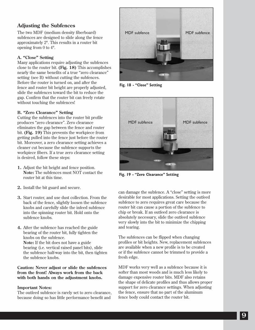
Adjusting the SubfencesThe two MDF (medium density fiberboard) subfences are designed to slide along the fenceapproximately 2". This results in a router bit opening from 0 to 4".
A. “Close” SettingMany applications require adjusting the subfencesclose to the router bit. (Fig. 18) This accomplishesnearly the same benefits of a true “zero clearance” setting (see B) without cutting the subfences.Before the router is turned on, and after the fence and router bit height are properly adjusted,slide the subfences toward the bit to reduce thegap. Confirm that the router bit can freely rotate without touching the subfences!
B. “Zero Clearance” SettingCutting the subfences into the router bit profile produces “zero clearance”. Zero clearance eliminates the gap between the fence and router bit. (Fig. 19) This prevents the workpiece from getting pulled into the fence just before the routerbit. Moreover, a zero clearance setting achieves a cleaner cut because the subfence supports theworkpiece fibers. If a true zero clearance setting is desired, follow these steps:
1. Adjust the bit height and fence position. Note: The subfences must NOT contact the router bit at this time.
2. Install the bit guard and secure.
3. Start router, and use dust collection. From the back of the fence, slightly loosen the subfence knobs and carefully slide the infeed subfence into the spinning router bit. Hold onto the subfence knobs.
4. After the subfence has reached the guide bearing of the router bit, fully tighten the knobs on the subfence.Note: If the bit does not have a guide bearing (i.e. vertical raised panel bits), slide the subfence half-way into the bit, then tighten the subfence knobs.
Caution: Never adjust or slide the subfencesfrom the front! Always work from the backwith both hands on the adjustment knobs.
Important Notes:The outfeed subfence is rarely set to zero clearance,because doing so has little performance benefit and
can damage the subfence. A “close” setting is moredesirable for most applications. Setting the outfeedsubfence to zero requires great care because therouter bit can cause a portion of the subfence tochip or break. If an outfeed zero clearance isabsolutely necessary, slide the outfeed subfencevery slowly into the bit to minimize the chippingand tearing.
The subfences can be flipped when changing profiles or bit heights. New, replacement subfencesare available when a new profile is to be created or if the subfence cannot be trimmed to provide afresh edge.
MDF works very well as a subfence because it issofter than most woods and is much less likely todamage expensive router bits. MDF also retains the shape of delicate profiles and thus allows propersupport for zero clearance settings. When adjustingthe fence, ensure that no part of the aluminumfence body could contact the router bit.
Fig. 19 - “Zero Clearance” Setting
Fig. 18 - “Close” Setting
MDF subfenceMDF subfence
MDF subfenceMDF subfence

10
Important Safety PointsBefore operating your router table please read this manual thoroughly. Safety and use tips are contained inthe manual. This page is not the sole source of safety information. Retain the manual for future reference.Refer to your router owner's manual for safety instructions regarding use of that tool. This manual is not aninstruction book on how to do woodworking with a power tool. We encourage all woodworkers to continually seek improvement in their woodworking skills, regardless of their craftsmanship or years of experience. Therouter table, fence and accessories must only be used for their intended purpose: woodworking via normal routing operations. “Normal operations” means basic shaping of wood in conditions where grounded electricity,sharp tools, dust, and rapidly spinning parts can be used or encountered safely. The following instructions elaborate on this concept.
1. Do not use your router table as a step or seat.2. The top and cabinet must be properly secured, and must be level before use. Inspect your table and base for
damage and levelness prior to each use.3. Keep work area clean, dry and well lit.4. The hardware affixing the insert to the router top must be installed for safe use. Tighten insert hold-down
screws before each use.5. Safe operation requires a router table fence, bit guard, dust collection system, starting pin or fulcrum, and
speed reducer for large diameter bits. We recommend reducing router speed for 1" or larger diameter bits. Consult your bit manufacturer for the exact speed.
6. Use the right tool for the job. Do not force a tool or attachment to do a job for which it was not designed.7. Secure your work with a featherboard, clamps, or a vice when appropriate. The use of inappropriate
accessories may cause injury.8. Wear safety glasses, dust mask, face shield and ear protection. This is not an exhaustive list. Every-day eye
glasses do not substitute for safety glasses.9. Do not wear gloves or jewelry while using a power tool and ProMAX10. Maintain your equipment and its accessories in good working condition. Look for wear, poor alignment of
moving parts, binding of moving parts, breakage, poor mounting, or other conditions that may affect operation and safety. Repair or replace any damaged parts.
11. Disconnect the power before moving, adjusting, or repairing parts, or otherwise maintaining your router table and any accessories you may be using.
12. Keep children, pets, and those who may disregard safety away from work area, cords, sockets and tools.13. Wear snug fitting clothes and keep long hair back to avoid catching in moving parts.14. Do not overreach. Maintain balanced footing and stance.15. Stay alert. Use common sense.
LIMITED TWO-YEAR WARRANTYWe make every effort to assure that our products meet quality and durability standards, and warrant to the original retail purchaser that this product is free from defects in materials and workmanship for two years. Remedyshall be limited to Bench Dog’s choice of repair, replacement or refund. This warranty does not provide remedyfor consequential economic loss.
This is a limited two-year warranty. It requires the purchaser to contact Bench Dog in writing within 30 days of discovering the defect. Warranty does not apply to defects due directly or indirectly to misuse, abuse, negligenceor accidents, repairs or alterations, or due to lack of maintenance. It excludes components and parts not manufactured by Bench Dog, defects caused by failure to provide a suitable installation environment, and damagecaused by use for purposes other than those for which the product was designed. Bench Dog, Inc. reserves theright to make product changes without notice and without obligation to make these changes on products previously sold. It excludes warranties of fitness for a particular purpose.
If the product is defective, we reserve the right to fix it, replace it, or refund the cost of the product to you.Typically, this results in a refund. All claims are limited to the two-year claims period. We must receive the productbefore a credit or refund will be issued. The warranty language on the product or in the product’s manual maycontain additional limitations, which govern.
If you wish to return something, call the dealer where you purchased the product. If you wish to return somethingpurchased from Bench Dog directly, call 1-800-786-8902 to receive an RMA number. Upon receipt and inspection ofthe goods, a credit or replacement will be issued for defective products. Return of nondefective items to BenchDog are subject to a 7% restocking charge. This is necessary due to the cost of checking, repackaging, and inventorying the stock.
BENCH DOG DISCLAIMS AND BUYER EXPRESSLY WAIVES ANY AND ALL WARRANTIES, EXPRESS ORIMPLIED, INCLUDING BUT NOT LIMITED TO, IMPLIED CONDITIONS OF FITNESS FOR A PARTICULARPURPOSE, MERCHANTABILITY, OR ANY OTHER MATTER.

11
Notes

12
Notes
Rev 02/09© 2009 Bench Dog Tools