Embed Size (px)
Citation preview

Prepayment Electricity Metering System
DOMESTIC Landis+Gyr
CASHPOWER SABRE MK 5 USER’S GUIDE

Filename: User Guide Sabre Mk5 Rev 0.0.doc Page 2 of 28
Revision History Revision Date Name/phone Comment a 2007-12-05 Paul Moolman Document creation 0.0 2008-11-06 Dave Tarr Updated for new Landis+Gyr branding and update of
product pictures
Abstract
This document is the User Guide for the Cashpower Sabre Mk5 Common Base keypad prepayment meters, designed and developed by Landis+Gyr (Pty) Ltd., South Africa
Referenced Documents
None
Landis+Gyr (Pty) Ltd. 60 Electron Avenue, Isando, Gauteng PO Box 281, Isando, 1600, South Africa Phone: +27 11 921 7900 Fax: +27 11 921 7901 Email: [email protected] Internet: www.za.landisgyr.com

Filename: User Guide Sabre Mk5 Rev 0.0.doc Page 3 of 28
Table of Contents
1. INTRODUCTION 5
2. ABBREVIATIONS 5
3. FRONT PANEL LAYOUT 6 3.1. Keypad 7 3.2. Liquid Crystal Display (LCD) 7 3.3. Rate of Consumption Indicator (Rate LED) 7 3.4. Meter Label Set 7 3.5. Anti-tamper sealing clips 7
4. LIQUID CRYSTAL DISPLAY (LCD) 8 4.1. Layout (what the icons mean) 8 4.2. Typical Operational Displays 9 4.3. Happy and Sad Faces 9 4.4. Contactor Status Indicators 9 4.5. Information Mode Indicator 10 4.6. Power Indicator (W) 10 4.7. Power Indicator (kWh) 10 4.8. Remaining Credit Indicator 10 4.9. Alarm Indicator 10
5. METER OPERATION 11 5.1. General 11 5.2. LCD Indications During Normal Operation 11 5.3. Entering Prepayment Vouchers via the Keypad 11 5.4. Voucher Processing 12
5.4.1. Incomplete Voucher 12 5.4.2. Complete Voucher 13
5.4.2.1. Voucher Accepted 13 5.4.2.2. Voucher Accepted as a Valid Key Change Number 13 5.4.2.3. Voucher Not Accepted By Meter 13 5.4.2.4. Duplicate Voucher 13 5.4.2.5. Expired Voucher 13 5.4.2.6. Voucher Overflow Rejection 13
5.5. Voucher Decryption and Processing 14 5.5.1.1. Electricity Credit Voucher 14 5.5.1.2. Set 1st Dispenser Key Voucher 14 5.5.1.3. Set 2nd Dispenser Key Voucher 14 5.5.1.4. Clear Tamper Voucher 14 5.5.1.5. Set Power Limit Voucher 15 5.5.1.6. Set Credit Alarm Levels Voucher (Proprietary Voucher) 15 5.5.1.7. Clear Credit Voucher 15 5.5.1.8. Initiate Dispenser Test Voucher (Meter Non-Specific Voucher) 15 5.5.1.9. Commissioning Voucher (Non Meter-Specific, Proprietary Voucher) 15 5.5.1.10. Commissioning Voucher (Meter-Specific, Proprietary Voucher) 16 5.5.1.11. Decommissioning Voucher (Meter-Specific, Proprietary Voucher) 16 5.5.1.12. Set Options Register (Meter-Specific, Proprietary Voucher) 16
5.6. Commissioning and Decommissioning the Meter 16 5.7. Power Limiting 16 5.8. Automatic/Manual Load Reconnection 17 5.9. Disconnect on Power Failure 17 5.10. Anti-tamper Features 18
5.10.1. General 18 5.10.2. Anti-Tamper Switch 19

Filename: User Guide Sabre Mk5 Rev 0.0.doc Page 4 of 28
5.10.3. Reverse Energy Detection 19 5.10.4. Magnetic Tamper Detection 19 5.10.5. Resetting a Tamper Condition 19
5.11. Virtual Token Carrier (VTC) Interface 20
6. INFORMATION FUNCTIONS 21 6.1. Meter Number (Register 000) 22 6.2. Instantaneous Power (Register 001) 22 6.3. Current Credit Register (Register 002) 22 6.4. Total Units Counter (Register 003) 23 6.5. Accumulated Credit Register (Register 005) 23 6.6. Current 30-Day Consumption (Register 008) 23 6.7. Previous 30-Day Consumption (Register 009) 23 6.8. Low Credit Level (Register 012) 23 6.9. High Credit Level (Register 013) 23 6.10. Power Limit Level (Register 014) 23 6.11. Meter State Register UPPER (Register 030) 24 6.12. Meter State Register LOWER (Register 031)1 24 6.13. Fixed Option Register (Register 033) 25 6.14. Changeable Option Register (Register 035) 25 6.15. Volatile Meter State – Upper (Register 036) 26 6.16. Volatile Meter State – Lower (Register 037) 26 6.17. Software Version Number (Register 048) 27 6.18. Power-Fail Counter (Register 050) 27 6.19. TN and ID Number of Last CTN Entered (Register 054) 27 6.20. ID Number of Last CTN Entered (Register 055) 27 6.21. Value of Last CTN Entered (Register 056) 27 6.22. Key Revision and Key Type (Register 057) 27 6.23. Tariff Index (Register 058) 27 6.24. Current Credit Register - 10Wh Resolution (Register 059) 27 6.25. SGC Register (Register 060) 27 6.26. Total Units Counter (10 Wh Resolution) (Register 061) 27 6.27. Last fifty 20 digit numbers entered into the meter 27 6.28. Customer Information Mode 28

Filename: User Guide Sabre Mk5 Rev 0.0.doc Page 5 of 28
1. INTRODUCTION
Cashpower Sabre ED Mk5 is a single phase “common base” prepayment meter specially designed to meet Eskom's prepayment metering requirements. This meter is most suited to new reticulation and is directly and easily interchangeable with meters from other manufacturers using the standard common base.
The plug-in base, which also conforms to Eskom's specifications, allows the commissioning of the meter to be done after the installation of the base, thereby adding flexibility and installation convenience. Included with the base is a Metal Oxide Varistor (MOV), which ensures that the meter complies with the stringent Eskom specifications for the protection of prepayment meters.
The base is optional and can be supplied separately to the meter.
Cashpower Sabre has an optional tamper facility, which will enable the meter to detect when it is being drawn out of the common base.
Figure 1: The Cashpower Sabre Prepayment Meter
2. ABBREVIATIONS
LCD Liquid Crystal Display
LED Light Emitting Diode
ED Electricity Dispenser

Filename: User Guide Sabre Mk5 Rev 0.0.doc Page 6 of 28
3. FRONT PANEL LAYOUT
The Sabre front panel comprises a non-tactile, 12-key keypad with audible feedback for the entry of tokens and accessing of various information registers, and a custom Liquid Crystal Display
Figure 2: Cashpower Sabre Front Panel Features
Figure 3: Close-up of the Cashpower Sabre membrane and LCD display features
Anti tamper sealing clip
Liquid Crystal Display (LCD)
Anti tamper sealing clips
Membrane with keypad and icon display indicators
LCD Display with icons
LCD icons
LCD icon indicators
Label with meter serial number and barcode
Information key
“Rate of Use” Indicator
Meter label with meter type and specification information
Backspace key
12 Digit Keypad

Filename: User Guide Sabre Mk5 Rev 0.0.doc Page 7 of 28
3.1. Keypad The 12-key keypad enables the entry of vouchers and the accessing of various information registers. Key-presses are acknowledged with an audible beep.
3.2. Liquid Crystal Display (LCD) The LCD normally displays remaining credit. The LCD also displays the scrolling in of keypad entries and various information functions. For details of the LCD icons, refer to paragraph 4.
3.3. Rate of Consumption Indicator (Rate LED) This red LED provides the reference output for verifying the meter’s metrological accuracy. It also provides a visual indication of rate of power consumption.
The meter constant for the Sabre ED meter is set to 1000 impulses/kWh. The rate LED will therefore flash 1000 times for every kWh of energy consumed.
3.4. Meter Label Set The meter label set shows the unique meter numbers, type number, and its associated parameters. The label on the right hand side of the keypad contains the meter serial number and bar code while the label on the left hand side of the keypad contains the meter type number and technical specifications such as voltage, maximum current, frequency etc.Anti-tamper sealing clips
3.5. Anti-tamper sealing clips On installation, the Sabre is secured to its socket base with two screws. These screws are then covered with a plastic anti tamper clip and finally sealed with utility-sealed wire seals on the front of the meter. The use of these utility seals ensures that there are visible signs of tampering from the front of the meter.

Filename: User Guide Sabre Mk5 Rev 0.0.doc Page 8 of 28
4. LIQUID CRYSTAL DISPLAY (LCD)
4.1. Layout (what the icons mean) The LCD is designed to give a clear and unambiguous visual indication of the important meter functions by means of language-independent pictograms. The LCD has three functional blocks: a numerical display for displaying various values such as remaining credit and power limit level, various pictograms such as the credit wedge, and pointers which point to pictograms on the membrane.

Filename: User Guide Sabre Mk5 Rev 0.0.doc Page 9 of 28
4.2. Typical Operational Displays
4.3. Happy and Sad Faces These two icons are used in combination to give a quick visual indication of good and bad status. For example, if the meter were operating normally, the happy face would be on. However, if it were to be tampered, the sad face would come on. Similar responses would apply during token entry e.g. entering an invalid CTN would result in the sad face flashing for a short period of time.
4.4. Contactor Status Indicators Two icons are used to indicate the status of the load-switch (an internal latching relay).
Under normal operating conditions i.e. with the meter in credit, the load switch will be ‘closed’ and power is supplied to the consumer. A second ‘open’ indicator is used to indicate that the latch is open, e.g. when credit expires.

Filename: User Guide Sabre Mk5 Rev 0.0.doc Page 10 of 28
4.5. Information Mode Indicator This icon turns on in response to pressing the i-key on the keypad. It indicates that the meter is in information mode and the contents of various registers can be viewed. Refer to paragraph 6.
4.6. Power Indicator (W) This function is used whenever the displayed units represent power (W), such as instantaneous power, or power limit setting. It applies to both normal meter operation as well as when viewing registers via the information mode.
4.7. Power Indicator (kWh) This function is used whenever the displayed units represent power (kWh). It applies to both normal meter operation as well as when viewing registers via the information mode.
The icon can be OFF or flashing. The icon will be ON when the latch is closed and the load exceeds the minimum creep load (typically 40mA)
The icon will be flashing when the latch is open and there is no load
4.8. Remaining Credit Indicator This ‘wedge’ provides a quick visual indication of the remaining credit in the meter.
NB: The actual credit levels at which the individual bars in the ‘wedge’ icon toggle are personalised at the time of manufacture but can be changed at any time with a maintenance token (refer to paragraphs 6.8 and 6.9 for details of viewing the credit level settings).
The indicator functions as follows:
• All four credit wedge icons are displayed if the value in the current credit register is above the preset high credit level.
• The three smallest wedge icons are displayed if the value in the current credit register is somewhere between the preset low credit level and high credit level.
• The two smallest wedge icons are displayed if the value in the current credit register is somewhere between the preset low credit level and half of that level.
• The smallest wedge icon is displayed if the value in the current credit register is somewhere between zero and half of the preset low credit level.
• All the credit wedge icons will be off when the meter runs out of credit (zero or negative values).
NB: When the remaining credit level reaches zero, the numeric display indicates 0.0 kWh. If, for any reason, the credit level is decremented below zero i.e. negative, the display indicates 0. kWh. This is the case if the meter has been personalised not to display negative credit – refer to paragraph 6.13. Although there is no negative value displayed, it gives a quick visual indication that a negative value is present (it is a requirement of some utilities to not show a negative credit value to consumers because in all likelihood it indicates tampering with the meter).
4.9. Alarm Indicator This is a ‘low credit’ warning indicator that turns on if the current credit register value is greater than zero, but less than half the low credit level. Under these conditions it is displayed in conjunction with the smallest credit wedge icon.

Filename: User Guide Sabre Mk5 Rev 0.0.doc Page 11 of 28
5. METER OPERATION
5.1. General In this section the features and functionality of the prepayment meter are described in detail.
5.2. LCD Indications During Normal Operation During normal operation, the LCD provides the following indications:
• Displays the current credit register value to a resolution of 0.1 kWh.
• Displays any combination of the credit wedge icons (0 to 4 segments depending on the actual current credit level in the meter.
• Displays the happy face icon, irrespective of the credit register value.
• Displays the load switch status icon in either the closed or open position, depending on whether the meter is in or out of credit.
• Flashes the ‘kWh’ icon if the meter is Creep mode (no power or very little power is consumed).
5.3. Entering Prepayment Vouchers via the Keypad Prepayment vouchers are entered into the meter by keying in the numbers printed on the credit voucher via the keypad. The numbers entered are displayed on the LCD as they are being entered and scroll from right to left, with a space displayed at every fourth digit for ease of viewing.
Visual feedback is provided by flashing the happy face icon with each key press.
Audible feedback is provided by a ‘beep’ on each key press.
Incorrect entries can be corrected with the backspace key (left arrow key), which removes the rightmost digit on the LCD with each press. Two backspace key presses in quick succession will clear the entire entry.
Acceptance of a valid prepayment voucher is automatic. Once a complete voucher has been entered, the meter processes it and, depending on the result, displays one of the sequences described in paragraph 5.4. Again, depending on what sequence is invoked, the keypad could remain locked for a variable period of time i.e. it will not respond in any way to further key presses.
An incomplete voucher entry will be timed-out after 30 seconds, after which the LCD reverts to normal operation.

Filename: User Guide Sabre Mk5 Rev 0.0.doc Page 12 of 28
Figure 4: Typical Happy & Sad face combinations
5.4. Voucher Processing Depending on the type of voucher entered into the meter, it will result in one of the display sequences described below:
5.4.1. Incomplete Voucher
A voucher entry is timed out if no key is pressed for more than 30 seconds. On time-out:
• The voucher number is cleared off the display.
• The remaining credit is displayed.
• The happy face icon is turned on.
• The sad face icon is flashed for 10 seconds.

Filename: User Guide Sabre Mk5 Rev 0.0.doc Page 13 of 28
5.4.2. Complete Voucher
If a complete voucher is entered, the meter:
• Locks the keypad.
• Proceeds to process the voucher number.
• Unlocks the keypad.
Depending on the result of the processing, one of the following sequences can occur:
5.4.2.1. Voucher Accepted
• A scrolling credit wedge is displayed.
5.4.2.2. Voucher Accepted as a Valid Key Change Number
Note: Two vouchers are required for a key change.
• The scrolling credit wedge is displayed.
• The key revision and key type, followed by the tariff index, is displayed during the above scrolling sequence.
5.4.2.3. Voucher Not Accepted By Meter
If the meter does not accept the voucher, it is rejected, and the following will be displayed:
• The happy face icon is turned off.
• The sad face icon is flashed for the reject time.
NB: The reject function is included to discourage the entry of random numbers in an attempt to defraud the meter. The reject time will eventually settle at a maximum time of 82.5 seconds.
5.4.2.4. Duplicate Voucher
If the voucher is rejected because it has previously been entered i.e. a duplicate voucher:
• Both the happy face and sad face icons are flashed simultaneously for 5 seconds.
5.4.2.5. Expired Voucher
If the voucher is rejected because it is older than the oldest voucher in the meter log i.e. ‘expired’:
• Both the happy face and sad face icons are alternately flashed for a period of 5 seconds.
5.4.2.6. Voucher Overflow Rejection
This occurs if the voucher is valid, but rejected because the current credit register would overflow. The following is displayed:
• The happy face icon is flashed.
• The sad face icon is turned on for 10 seconds.
NB: The voucher can be re-used at a later stage.

Filename: User Guide Sabre Mk5 Rev 0.0.doc Page 14 of 28
5.5. Voucher Decryption and Processing The meter accepts information transferred as specified in the Standard Transfer Specification release 1.0:1995 with key typing included. Key expiry is not implemented.
STS vouchers comprise of 20-digit numbers.
The following STS voucher types will be recognised and accepted:
• Electricity credit (meter-specific voucher) – refer to paragraph 5.5.1.1.
• Set 1st dispenser key (meter-specific voucher) - refer to paragraph 5.5.1.2.
• Set 2nd dispenser key (meter-specific voucher) - refer to paragraph 5.5.1.3.
• Clear tamper (meter-specific voucher) - refer to paragraph 5.5.1.4.
• Set maximum power load or power limit level (meter-specific voucher) - refer to paragraph 5.5.1.5.
• Set current credit levels (meter-specific, proprietary voucher) - refer to paragraph 5.5.1.6.
• Clear credit (meter-specific, proprietary voucher) - refer to paragraph 5.5.1.7.
• Initiate dispenser test (non meter-specific voucher) - refer to paragraph 5.5.1.8.
• Commissioning voucher (non meter-specific, proprietary voucher) - refer to paragraph 5.5.1.9.
• Commissioning voucher (meter-specific, proprietary voucher) - refer to paragraph 5.5.1.10.
• Decommissioning voucher (meter-specific, proprietary voucher) - refer to paragraph 5.5.1.11.
• Set Options Register (meter-specific, proprietary voucher) – Refer to paragraph 5.5.1.12 below.
5.5.1.1. Electricity Credit Voucher
The electricity credit voucher transfers a variable quantity of credit to the meter.
5.5.1.2. Set 1st Dispenser Key Voucher
Key changes are occasionally carried out to maintain the security of a pre-payment system. Unless the prepayment vending system and meter are both operating on the same key, vouchers vended from that system will not be accepted by the meter.
To effect a key change, two vouchers (set 1st dispenser key and set 2nd dispenser key) need to be issued and entered into the meter within a 5-minute period of each other. NB: set 1st dispenser key and set 2nd dispenser key vouchers may be entered in any sequence i.e. the 2nd dispenser key voucher may be entered first.
Note: Various ancillary functions e.g. clearing the meter log may be embedded into the key-change process (refer to the STS specification).
5.5.1.3. Set 2nd Dispenser Key Voucher
Refer to paragraph 5.5.1.2 above.
5.5.1.4. Clear Tamper Voucher
If a meter has been tampered, normal operation can only be restored by entering a clear tamper voucher. Note that these vouchers also reset the power-fail counter.
Note: the “TAMPER DETECT” function in the meter is NOT set as for previous versions of meter software.
Filename: User Guide Sabre Mk5 Rev 0.0.doc Page 15 of 28
5.5.1.5. Set Power Limit Voucher
This voucher sets the power limit level for the meter – refer to paragraph 5.7.
5.5.1.6. Set Credit Alarm Levels Voucher (Proprietary Voucher)
On accepting a credit alarm level number, the meter sets the appropriate high and low credit levels. These are the levels at which the segments in the ‘wedge’ of the LCD credit indicator toggle – refer to paragraph 4.8 above.
Note: If any of the credit levels transferred via the token is zero, the token is accepted, but the respective credit level is not updated.
Note: The set credit levels token is not defined in the STS specification. It is a CASHPOWER specific feature, and it uses one of the proprietary dispenser specific management token subclasses.
5.5.1.7. Clear Credit Voucher
On accepting a clear credit voucher, the meter clears any remaining credit to zero and opens the load switch, thus interrupting the electricity supply to the customer.
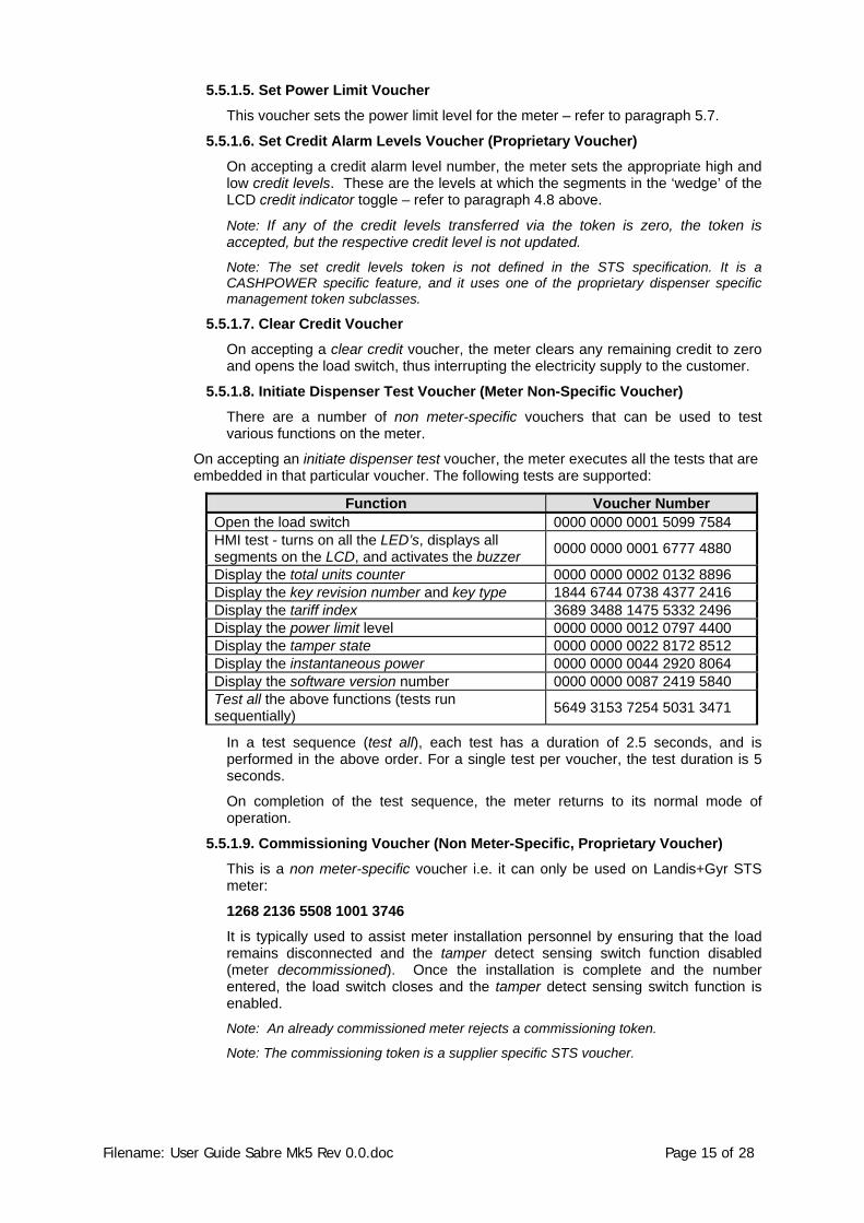
5.5.1.8. Initiate Dispenser Test Voucher (Meter Non-Specific Voucher)
There are a number of non meter-specific vouchers that can be used to test various functions on the meter.
On accepting an initiate dispenser test voucher, the meter executes all the tests that are embedded in that particular voucher. The following tests are supported:
Function Voucher Number Open the load switch 0000 0000 0001 5099 7584 HMI test - turns on all the LED’s, displays all segments on the LCD, and activates the buzzer 0000 0000 0001 6777 4880
Display the total units counter 0000 0000 0002 0132 8896 Display the key revision number and key type 1844 6744 0738 4377 2416 Display the tariff index 3689 3488 1475 5332 2496 Display the power limit level 0000 0000 0012 0797 4400 Display the tamper state 0000 0000 0022 8172 8512 Display the instantaneous power 0000 0000 0044 2920 8064 Display the software version number 0000 0000 0087 2419 5840 Test all the above functions (tests run sequentially) 5649 3153 7254 5031 3471
In a test sequence (test all), each test has a duration of 2.5 seconds, and is performed in the above order. For a single test per voucher, the test duration is 5 seconds.
On completion of the test sequence, the meter returns to its normal mode of operation.
5.5.1.9. Commissioning Voucher (Non Meter-Specific, Proprietary Voucher)
This is a non meter-specific voucher i.e. it can only be used on Landis+Gyr STS meter:
1268 2136 5508 1001 3746
It is typically used to assist meter installation personnel by ensuring that the load remains disconnected and the tamper detect sensing switch function disabled (meter decommissioned). Once the installation is complete and the number entered, the load switch closes and the tamper detect sensing switch function is enabled.
Note: An already commissioned meter rejects a commissioning token.
Note: The commissioning token is a supplier specific STS voucher.

Filename: User Guide Sabre Mk5 Rev 0.0.doc Page 16 of 28
5.5.1.10. Commissioning Voucher (Meter-Specific, Proprietary Voucher)
This is a meter-specific voucher but in all other aspects its operation is the same as described in paragraph 5.5.1.9.
Note: An already commissioned meter rejects a commissioning token.
5.5.1.11. Decommissioning Voucher (Meter-Specific, Proprietary Voucher)
On accepting a decommissioning voucher, the meter opens the load switch (load disconnected) and disables the tamper detect sensing switch function.
Note: An already decommissioned meter rejects a commissioning token.
5.5.1.12. Set Options Register (Meter-Specific, Proprietary Voucher)
On accepting this voucher, the “Changeable Options Register 0” is set according to the 8-bit value in the token. Care must be taken when using this feature, as the operator would not know the settings in the meter, and various parameters could be set/reset. The parameters are as follows:
Enable/Disable Tamper Function
Tamper / Do Not Tamper on Significant Reverse Energy
Disconnect / Do Not Disconnect on Power-Fail
Non Automatic / Automatic Latch Reconnect
Refer to paragraph 6.14 for more detail.
5.6. Commissioning and Decommissioning the Meter The function of being able to set the meter into the decommissioned / commissioned mode offers several advantages to meter installation personnel. If power is applied to the meter during installation and the meter terminal cover not yet in place, the meter will detect this and enter into the tampered mode, thereby disconnecting the supply to the customer. A meter-specific tamper reset voucher then needs to be generated at the vending system to rectify the situation.
When setting the meter into the decommissioned mode, the following occurs:
• The tamper detect sensing switch function is disabled.
• The load switch is set into the open state.
• When setting the meter into the commissioned mode, the following occurs:
• The tamper detect sensing switch function may be either enabled or disabled.
• The load switch operates as normal.
• The meter’s commissioned / decommissioned status can be observed in the meter state register - refer to paragraph 6.11.
5.7. Power Limiting The power-limiting feature allows utilities to set the maximum load that can be drawn by customers. The setting can be changed when necessary via a set power limit voucher from the prepayment vending system.
Eskom specification DISCAAA9 makes specific reference to a power-limiting algorithm. This algorithm is included in the meter’s software and is implemented as follows:
• If the preset power limit threshold is exceeded, the load switch will open for a period of 30 seconds (power limit trip period), after which it will re-close (either automatically or manually - refer to paragraph 5.8). If the power limit threshold continues to be exceeded, the above process is repeated. If, after 4 power-limit events within a 15-minute window, the limit is still being exceeded because of excessive energy consumption, the load switch will be opened for a period of 30 minutes (the power limit lockout period). At the end of the lockout period, the load switch will re-close

Filename: User Guide Sabre Mk5 Rev 0.0.doc Page 17 of 28
(either automatically or via a manual operation on the keypad - refer to paragraph 5.8) and, unless the excessive loading has been removed, the process will be repeated. Note that vouchers may be entered and the information modes accessed as normal during the power limit lockout period.
• If the power drawn by the customer is reduced in response to a power limit disconnect, the event will be ignored after 15 minutes has elapsed.
• The LCD will display the following during the two conditions:
Figure 5: LCD Showing "Power Limit Trip" - Disconnection for a 30 second period
Figure 6: LCD Showing "Power Limit Lockout" - Disconnection for a 30 minute period
NB: Power Limit is not a form of safety overload protection. It is designed to generally limit the overall usage of power in a particular area (possibly dictated by reticulation limitations or linked to a tariff allocation).
5.8. Automatic/Manual Load Reconnection In some instances, local safety regulations require that the meter not automatically re-close the load switch after, for example, a power limit trip. Under these conditions, the load switch will remain in the open state until such time as a key is pressed on the keypad.
Using the example of a power limit trip – refer to paragraph 5.7, the load switch will open and remain open for a period of 30 seconds. At the end of this 30-second period, the display will return to normal but, instead of the load switch closing, the load switch status icon on the LCD will start to flash, toggling between an open and closed state. This is a visual indication that the load switch may now be manually closed, by pressing any key on the keypad.
In the event of the load switch opening due to expiry of credit, it will only be able to close again on entry of a valid credit voucher. The manual action of entering a credit voucher via the keypad, results in the load switch closing when the last digit of the voucher is entered and accepted by the meter.
Automatic/manual load reconnection is a configurable option, set at the time of manufacture – refer to paragraph 6.14. It may also be changed at any stage with a suitable engineering voucher.
5.9. Disconnect on Power Failure This option, configurable at the time of manufacture, refer to paragraph 6.14, forces the meter’s load switch to open whenever there is a power failure. The option can be invoked as a means of preventing the meter from being installed fraudulently with line and load connections reversed, in which case the meter will never power up once the load switch is open.

Filename: User Guide Sabre Mk5 Rev 0.0.doc Page 18 of 28
5.10. Anti-tamper Features 5.10.1. General
The Sabre meter is mechanically sealed against tampering through the use of a factory-sealed screw plugs on the rear panels and a utility-sealed wire seal on the front of the meter.
The use of these mechanical seals ensures that there are visible signs of tampering if unauthorised entry to the system is attempted.
Figure 7: Factory sealed screw plugs
In addition to the factory-sealed screw plugs on the rear panels, there is a facility for two utility wire seals on the front of the meter. The use of these utility seals also ensures that there are visible signs of tampering.
Once the meter has been securely fitted to the common base and secured with the screws supplied, the anti-tamper seals are clipped in place and utility seals are fitted into the holes as shown below.
Figure 8: Anti-tamper sealing clip
Holes for utility sealing wires

Filename: User Guide Sabre Mk5 Rev 0.0.doc Page 19 of 28
5.10.2. Anti-Tamper Switch
Sabre meters with mechanical anti-tamper facility fitted are available on request.
The tamper facility automatically detects if the meter is removed from the common base. This condition will set the tamper condition thereby opening the latching relay when the meter is re-fitted to the base.
The Tamper Detect function may be enabled or disabled during production, or by means of a Set Options Register token – refer to paragraph 5.5.1.12 and paragraph 6.14 for more detail.
The tampered condition may be monitored by using the information functions – refer to paragraph 6.12 – or by using the initiate dispenser test voucher (display the tamper state) as described in paragraph 5.5.1.8.
Figure 9: Anti-tamper switch
5.10.3. Reverse Energy Detection
The meter includes a Significant Reverse Energy (SRE) detection feature. If the line and load wires are swapped during installation, the meter will continue to operate and decrement credit, however, the meter can be factory-programmed to tamper and disconnect the load should SRE be detected.
The reverse energy condition may be monitored by using the information functions – refer to paragraph 6.12.
5.10.4. Magnetic Tamper Detection
This new generation meter now incorporates a magnetic tamper detector. When the meter senses a magnetic field strength above a pre-programmed threshold level, it disconnects the supply to the consumer.
As with the power limit trip condition, the magnetic tamper condition opens the internal latching relay for 30 seconds. Should magnetic interference be detected more than 5 times in a 15 minute window, the latching relay will open for 30 minutes.
The Magnetic Tamper state may be monitored by using the information functions – refer to paragraph 6.15.
5.10.5. Resetting a Tamper Condition
Before resetting a tamper condition, care must be taken to remove the cause of the condition, eg ensure that the tamper switch is closed. Failing to do this will cause an immediate tamper condition.
If a meter has been tampered, normal operation can only be restored by entering a clear tamper voucher.
As can be seen from the enlarged view – the tamper switch is not fitted in this instance. In the event that a tamper switch is fitted to the meter, a small plastic plunger will be visible.

Filename: User Guide Sabre Mk5 Rev 0.0.doc Page 20 of 28
5.11. Virtual Token Carrier (VTC) Interface This port is available via a removable plug at the rear of the meter and should only be accessed when the meter is disconnected from power. It allows for meter data such as remaining credit to be extracted in the event of an electronics failure.
NB: From a safety point of view, the meter must not be powered when accessing this port the Credit Reader provides the necessary low-voltage supply to power the logic circuitry.
Figure 10: Virtual Token Carrier (VTC) port

Filename: User Guide Sabre Mk5 Rev 0.0.doc Page 21 of 28
6. INFORMATION FUNCTIONS
Pressing the i-key toggles the meter into information mode (the ‘i’-icon on the LCD turns on and all digits display ≡≡≡≡≡≡≡). The contents of various registers can now be viewed by entering the appropriate, three digit register code.
Once in information mode, toggling between different registers may now be done on an ongoing basis by entering the appropriate three-digit code i.e. the information key does not have to be pressed again.
Information mode may be exited by pressing the information-key or, in the absence of any other key presses, automatically after 1 minute.
Information Register Functions
Info Register Number Function / Meter Parameter
000 11-Digit Electricity Dispenser Number
001 Instantaneous Power
002 Current Credit Register
003 Total Units Counter
005 Accumulated Credit Register
008 Current 30-day Consumption
009 Previous 30-day Consumption
012 Low Credit Level
013 High Credit Level
014 Power Limit Level
030 Meter State Register – Upper
031 Meter State Register – Lower
032 (Fixed) Option Register – Upper (Not used)
033 (Fixed) Option Register – Lower
Information key

Filename: User Guide Sabre Mk5 Rev 0.0.doc Page 22 of 28
Information Register Functions
Info Register Number Function / Meter Parameter
034 Changeable Option Register – Upper (Not used)
035 Changeable Option Register – Lower
036 Volatile Meter State Register – Upper
037 Volatile Meter State Register – Lower
048 Software Version Number
050 Power-fail Counter
054 Last Credit Token 20-Digit Transfer Number and ID in date/time format
055 Last Credit Token ID
056 Value of Credit for Last Credit Token entered
057 Key Revision and Key Type
058 Tariff Index
059 Current Credit Register (10 Wh resolution)
060 Supply Group Code Register
061 Total Units Counter (10 Wh resolution)
301 Last Token’s 20-Digit Transfer Number and ID in Date/Time Format
302 2nd Last Token’s 20-Digit Transfer Number and ID in Date/Time Format
… …
350 50th Last Token’s 20-Digit Transfer Number and ID in Date/Time Format
600 Enter Customer Information Mode (Refer to section 6.28)
6.1. Meter Number (Register 000) The meter displays the unique identity number personalised at the time of manufacture. The serial number scrolls on the display from right to left. It must match the number printed on the meter’s front panel label.
6.2. Instantaneous Power (Register 001) The meter displays the power currently being consumed by the connected load.
6.3. Current Credit Register (Register 002) This register stores the remaining credit in the meter. This register has a minimum value of -99 999.99 kWh, and a maximum value of 9 999 999.99 kWh.
Note: When more than seven digits are to be displayed (e.g. 1234567.8), the decimal digits are dropped.
Note: The remaining credit can be decremented past zero (0) into negative values if the load is not disconnected. This negative credit value will be subtracted from any new credit entered into the meter.

Filename: User Guide Sabre Mk5 Rev 0.0.doc Page 23 of 28
6.4. Total Units Counter (Register 003) The meter displays the total kWh consumed since the meter was put into service. This register will have a value of between 0 kWh and 9’999’999.99 kWh.
6.5. Accumulated Credit Register (Register 005) The meter displays the total kWh entered into the meter, via tokens. This register will have a value of between 0 kWh and 9’999’999.99 kWh.
6.6. Current 30-Day Consumption (Register 008) The meter displays the number of days into the current 30-day period, followed by the consumption in kWh. By pressing the information-key twice in quick succession, the day counter and consumption is reset to zero.
The display is days (on left hand side) and consumption (on right hand side)
6.7. Previous 30-Day Consumption (Register 009) The meter displays the previous 30-day period consumption.
6.8. Low Credit Level (Register 012) The meter displays the level at which the lower two credit wedges on the LCD come into operation.
The meter could have a value of between 6.4 kWh and 1 632 kWh, with a 6.4 kWh resolution.
6.9. High Credit Level (Register 013) The meter displays the level at which the upper two credit wedges on the LCD come into operation.
The meter could have a value of between 128 kWh and 32 640 kWh, with a 128 kWh resolution.
6.10. Power Limit Level (Register 014) The meter displays the power level at which the load switch will be opened, causing the supply to the consumer to be interrupted. The value of this register could be between 0 and 65’535 Watt.

Filename: User Guide Sabre Mk5 Rev 0.0.doc Page 24 of 28
6.11. Meter State Register UPPER (Register 030)1 The meter displays the most significant eight bits of the meter state register. This register indicates the current state of the following meter functions:
Meter State Register – Upper
Display Function
1xxx xxxx Not Used
x1xx xxxx Not used
xx1x xxxx Not used
Xxx1 xxxx Not used
Press ‘030’ to toggle between UPPER set and LOWER sets of 4 numbers
xxxx 1xxx Not used
xxxx x1xx Not used
xxxx xx1x Not used
xxxx xxx1 Waiting for Keypress (if non-auto latch reconnect enabled)
6.12. Meter State Register LOWER (Register 031)1 The meter displays the least significant eight bits of the meter state register. This register indicates the current state of the following meter functions:
Meter State Register – Lower
Display Function
1xxx xxxx Latch Inhibit
X1xx xxxx Significant reverse power metered
xx1x xxxx Not used
Xxx1 xxxx Meter decommissioned
Press ‘031’ to toggle between UPPER set and LOWER sets of 4 numbers
xxxx 1xxx Meter NOT initialised (default key)
xxxx x1xx Meter in power limit trip
xxxx xx1x Meter out of credit
xxxx xxx1 Meter tampered
1 Because eight digits need to be displayed, but only 7 digits are available on the display, the number to be displayed is grouped into two sets of four numbers each. The upper set is displayed on the left hand side of the display, whilst the lower set is displayed on the right hand side. To toggle between the upper and lower sets, re-enter the three digit code for that register (without pressing the information-key).

Filename: User Guide Sabre Mk5 Rev 0.0.doc Page 25 of 28
6.13. Fixed Option Register (Register 033) The meter displays the least significant eight bits of the meter fixed option register. The contents of this register are determined at the time of manufacture and cannot be subsequently changed via a token:
Fixed Option Register – Lower
Display Function
1xxx xxxx Not used
x1xx xxxx Not used
xx1x xxxx Not used
Xxx1 xxxx Not used
Press ‘033’ to toggle between UPPER set and LOWER sets of 4 numbers
xxxx 1xxx Not used
xxxx x1xx Enable creep lock
xxxx xx1x Display negative credit
xxxx xxx1 Reserved - must be set to 1
6.14. Changeable Option Register (Register 035) The meter displays the least significant eight bits of the meter changeable option register. The contents of this register are determined at the time of manufacture and cannot be subsequently changed via a token:
Changeable Option Register – Lower
Display Function
1xxx xxxx Not used
x1xx xxxx Not used
xx1x xxxx Tamper function enabled
Xxx1 xxxx Tamper on significant reverse power
Press ‘035’ to toggle between UPPER set and LOWER sets of 4 numbers
xxxx 1xxx Disconnect on power fail
xxxx x1xx Not used
xxxx xx1x Non-auto latch reconnect
xxxx xxx1 Not used

Filename: User Guide Sabre Mk5 Rev 0.0.doc Page 26 of 28
6.15. Volatile Meter State – Upper (Register 036) The meter displays the most significant eight bits of the volatile meter state register. This register indicates the current state of the following meter functions:
Volatile Meter State Register – Upper
Display Function
1xxx xxxx Not Used
x1xx xxxx Not used
xx1x xxxx Not used
Xxx1 xxxx Not used
Press ‘036’ to toggle between UPPER set and LOWER sets of 4 numbers
xxxx 1xxx Production Engineering Mode Enable
xxxx x1xx Not used
xxxx xx1x Reason for latch hold-back: Overload / Magnetic trip
xxxx xxx1 Phase direction indicator
6.16. Volatile Meter State – Lower (Register 037) The meter displays the least significant eight bits of the volatile meter state register. This register indicates the current state of the following meter functions:
Meter State Register – lower
Display Function
1xxx xxxx Meter Creep Lock Condition
x1xx xxxx Not used
xx1x xxxx Not used
Xxx1 xxxx Tamper Switch State
Press ‘037’ to toggle between UPPER set and LOWER sets of 4 numbers
xxxx 1xxx Not Used
xxxx x1xx Not used
xxxx xx1x DC Magnetic Field Detected
xxxx xxx1 DC Magnetic Field Trip State

Filename: User Guide Sabre Mk5 Rev 0.0.doc Page 27 of 28
6.17. Software Version Number (Register 048) The meter displays the software version number masked into the microprocessor.
6.18. Power-Fail Counter (Register 050) The meter displays the number of power failures that have occurred since installation. This register is cleared with the entry of a tamper reset token.
6.19. TN and ID Number of Last CTN Entered (Register 054) The meter scrolls the last Credit Transfer Number and the Token Identifier on the LCD.
6.20. ID Number of Last CTN Entered (Register 055) The token identifier is displayed (0 – 16777215) i.e. number of minutes elapsed since 01:01:1993.
6.21. Value of Last CTN Entered (Register 056) The meter displays the value (kWh) of the last Credit Transfer Number entered.
6.22. Key Revision and Key Type (Register 057) Refer to the STS specification
6.23. Tariff Index (Register 058) Refer to the STS specification
6.24. Current Credit Register - 10Wh Resolution (Register 059) The meter displays the value of the credit register with a resolution of 0.01kWh. The most significant digit of the display (if in use) will be “pushed” off the display in this mode.
6.25. SGC Register (Register 060) This register will contain the initial SGC value, personalised at the time of manufacture. Once a successful STS meter key-change has been performed, the information is no longer valid and is, therefore, cleared. This option gives a quick indication of whether a key-change has been performed on the meter.
6.26. Total Units Counter (10 Wh Resolution) (Register 061) The meter displays the total kWh consumed, with a resolution of 0.01kWh, since the meter was put into service.
6.27. Last fifty 20 digit numbers entered into the meter Meter stores the last 50 STS numbers entered into the meter in 50 separate registers. As follows:
• Register 301 Last 20 digit voucher entered
• Register 302 2nd Last 20 digit voucher entered
• Register 303 to Register 349 – 3rd last to 49th last vouchers
• Register 350 50th last voucher entered

Filename: User Guide Sabre Mk5 Rev 0.0.doc Page 28 of 28
6.28. Customer Information Mode The Customer Information Mode is entered via info-register 600. On entering the Customer Information Mode, meter will display as follows:
• All lines on the display (typical information mode display)
• Information mode icon flashing
Now enter the register number in the table below
Code Function
000 test all
001 open the disconnect-device
002 switch all LCD segments on and flash the rate LED
004 display total units counter
005 display key revision and key type
006 display tariff index
007 display power limit level
008 display the meter tamper status
009 display available credit
030 display the meter supply group code
050 instantaneous power
100 display the meter number
101 display the software version number
102 display the VTC mapping number
200 display value of last credit token
201 display id of last credit token