Embed Size (px)
Citation preview

Case Study: Wear Mechanisms of NiCrVMo-steel and CrB-steel Scrap Shear Blades
ABBASI, Erfan, LUO, Quanshun <http://orcid.org/0000-0003-4102-2129> and OWENS, Dave
Available from Sheffield Hallam University Research Archive (SHURA) at:
http://shura.shu.ac.uk/17468/
This document is the author deposited version. You are advised to consult the publisher's version if you wish to cite from it.
Published version
ABBASI, Erfan, LUO, Quanshun and OWENS, Dave (2018). Case Study: Wear Mechanisms of NiCrVMo-steel and CrB-steel Scrap Shear Blades. Wear, 398-39, 29-40.
Copyright and re-use policy
See http://shura.shu.ac.uk/information.html
Sheffield Hallam University Research Archivehttp://shura.shu.ac.uk
brought to you by COREView metadata, citation and similar papers at core.ac.uk
provided by Sheffield Hallam University Research Archive

Author’s Accepted Manuscript
Case Study: Wear Mechanisms of NiCrVMo-steeland CrB-steel Scrap Shear Blades
Erfan Abbasi, Quanshun Luo, Dave Owens
PII: S0043-1648(17)31384-4DOI: http://dx.doi.org/10.1016/j.wear.2017.11.014Reference: WEA102296
To appear in: Wear
Cite this article as: Erfan Abbasi, Quanshun Luo and Dave Owens, Case Study:Wear Mechanisms of NiCrVMo-steel and CrB-steel Scrap Shear Blades, Wear,http://dx.doi.org/10.1016/j.wear.2017.11.014
This is a PDF file of an unedited manuscript that has been accepted forpublication. As a service to our customers we are providing this early version ofthe manuscript. The manuscript will undergo copyediting, typesetting, andreview of the resulting galley proof before it is published in its final citable form.Please note that during the production process errors may be discovered whichcould affect the content, and all legal disclaimers that apply to the journal pertain.
www.elsevier.com/locate/wear
1
Case Study: Wear Mechanisms of NiCrVMo-steel and CrB-
steel Scrap Shear Blades
Erfan Abbasi a,b,*
, Quanshun Luo a, Dave Owens
b
a Materials and Engineering Research Institute, Sheffield Hallam University, Howard Street, Sheffield, S1 1WB, UK
b Tyzack Machine Knives Ltd, Shepcote Lane, Sheffield, S9 1TG, UK
* Corresponding author. Tel.: +44 (0) 114 221 1059
E-mail address: [email protected] (E. Abbasi)
Abstract
Shear blades are extensively used in the recycling of metal scrap. A comparative study was
conducted on used medium carbon NiCrVMo and CrB containing steel scrap shear blades to better
understand their wear mechanisms under service conditions. The microstructure and hardness of
worn cutting edges and bulk material were characterised by optical microscopy, scanning electron
microscopy and microanalysis, X-ray diffraction analysis and macro/micro hardness testing.
Moreover, tensile and Charpy impact properties were obtained from the bulk material. Several wear
mechanisms were identified in both blades which are categorised in two main groups, i.e. spalling
and progressive wear. The progressive wear due to abrasive, adhesive and oxidation wear was
observed in both blades. In NiCrVMo-steel blades, spalling and crack propagation from
surface/subsurface white etching layers mainly caused the severe wear. However, spalling due to
delamination wear and crack propagation from severely deformed subsurface layers was the
dominant severe wear mechanism in CrB-steel blades.
Keywords: Impact/sliding wear, Wear mechanism, Progressive wear, Spalling wear, Scrap shear
blade
1. Introduction
The scrap shearing process primarily comprised a dry impact/sliding induced shear
deformation in scraps. This can in turn cause severe wear in shearing blades, especially in sharp
cutting edges. However, improving the wear performance of blades, or in general cutting tools, can
increase the speed of shearing process, reduce the required shearing forces and minimise the
maintenance costs of machines [1,2,3].

2
Controlling and improving the wear resistance of shear blades during shearing processes
require a subtle design of geometry, chemical composition and heat treatment [2,4]. In this way,
medium or high carbon high strength steels with high hardness, toughness, fracture toughness,
strength and fatigue resistance have been introduced by steel makers for different applications and
are widely used to produce shear blades. To manipulate the microstructure and control the
mechanical properties of steels, blades are usually produced through quench-hardening, quench-
tempering or quench-partitioning processes, depending on steel grade, e.g. [5]. The outstanding
mechanical properties of these steels are mainly attributed to their microstructure, comprising a high
dislocation density and fine lath shaped martensite/bainite or tempered-martensite [6,7,8]. However,
further improvements to the wear resistance of scrap shear blade steels are still sought. The
improvements should also be able to be achieved by existing manufacturing facilities and to meet
cost reduction demands. This has driven the need for further investigations into the wear behaviour
of high strength steels with different alloying additions and microstructures, and different wear
conditions (e.g. sliding wear and impact wear) [9,10,11].
Depending on wear conditions, different mechanical properties (e.g. hardness and toughness)
have been investigated against the chemical composition and microstructure of steels to understand
wear mechanisms and consequently improve their wear resistant, e.g. [3,5]. The wear resistant have
been widely improved by controlling the thermal conductivity and size, morphology and distribution
of existing phases, precipitates, retained austenite and non-metallic inclusions. In this case, although
many investigations have been conducted on the laboratory scale wear experiments of different high
strength steels, no detailed study has been reported on the wear behaviour of scrap shear steel blades
under service conditions, e.g. [12,13,14,15]. Due to complex wear conditions between blade and
scrap during shearing process, it is difficult to estimate the wear mechanisms of blades from the
laboratory scale simulations. Therefore, in this work a study was conducted on used blades made
from two types of steels and with different lifetimes, to better understand wear mechanisms and their
relation to the microstructure.
2. Experimental procedure
Commercial used blades received from end-users and they were used to cut scrap steels at
ambient temperature under actual conditions. Table 1 compares the chemical composition of studied
blades. The amount of each element was determined using a spark Optical Emission Spectroscopy
(OES) technique. Consequently, the two sample blades were designated as “NiCrVMo” and “CrB”
in this paper. The materials used for the blades were two medium carbon steels which were
specifically designed to produce scrap shear blades. The NiCrVMo blade was heat treated by oil-
3
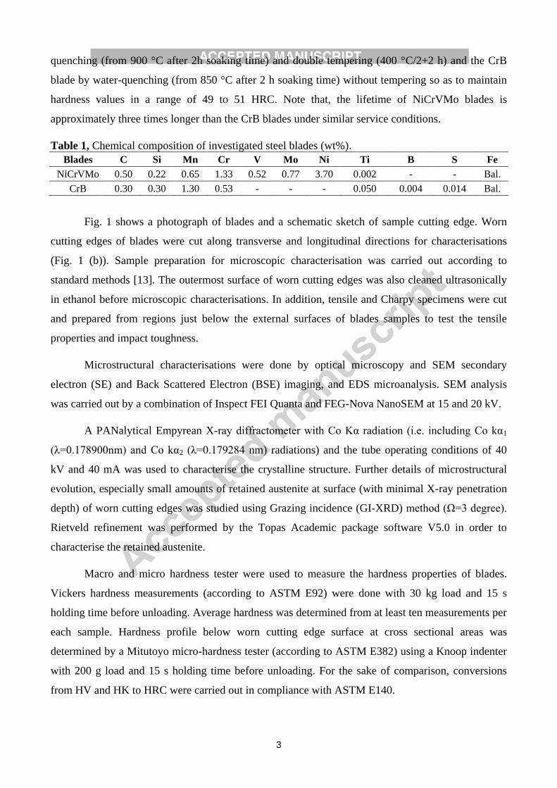
quenching (from 900 °C after 2h soaking time) and double tempering (400 °C/2+2 h) and the CrB
blade by water-quenching (from 850 °C after 2 h soaking time) without tempering so as to maintain
hardness values in a range of 49 to 51 HRC. Note that, the lifetime of NiCrVMo blades is
approximately three times longer than the CrB blades under similar service conditions.
Table 1, Chemical composition of investigated steel blades (wt%).
Blades C Si Mn Cr V Mo Ni Ti B S Fe
NiCrVMo 0.50 0.22 0.65 1.33 0.52 0.77 3.70 0.002 - - Bal.
CrB 0.30 0.30 1.30 0.53 - - - 0.050 0.004 0.014 Bal.
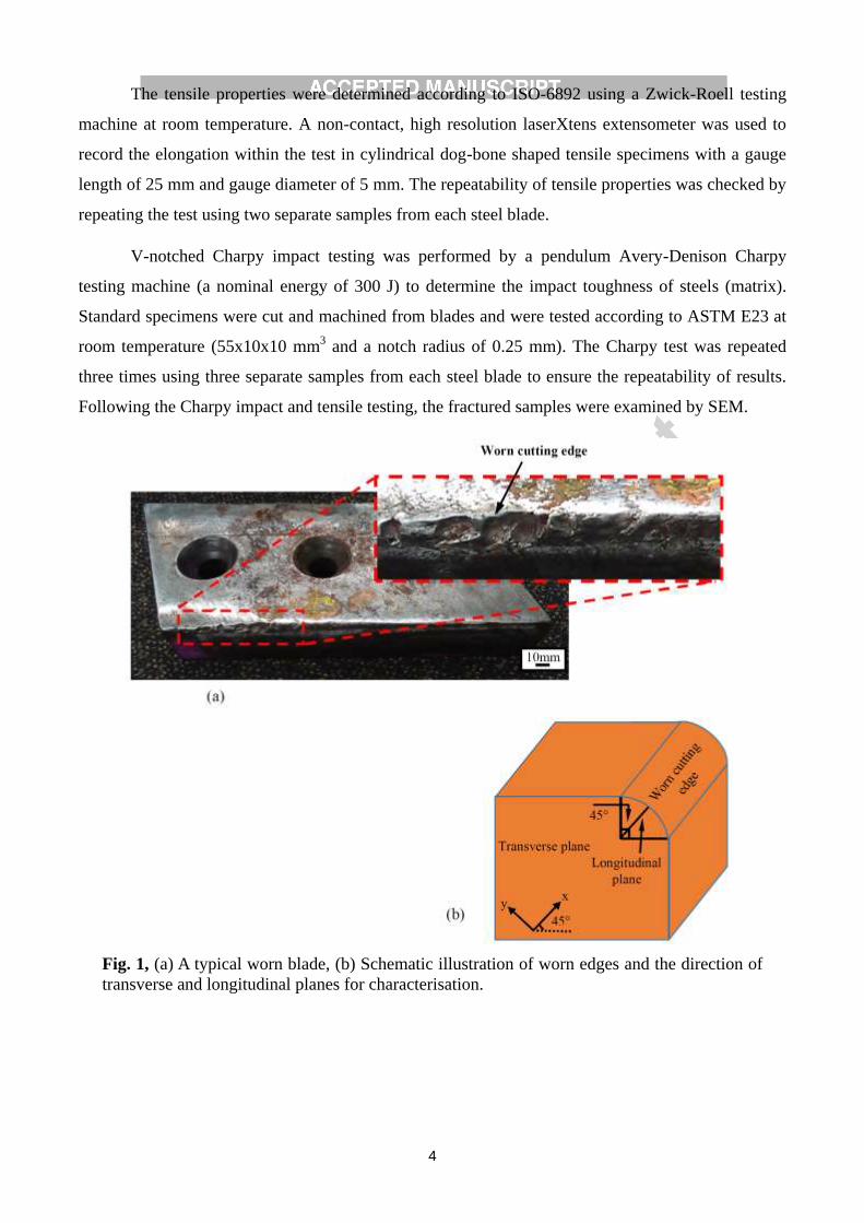
Fig. 1 shows a photograph of blades and a schematic sketch of sample cutting edge. Worn
cutting edges of blades were cut along transverse and longitudinal directions for characterisations
(Fig. 1 (b)). Sample preparation for microscopic characterisation was carried out according to
standard methods [13]. The outermost surface of worn cutting edges was also cleaned ultrasonically
in ethanol before microscopic characterisations. In addition, tensile and Charpy specimens were cut
and prepared from regions just below the external surfaces of blades samples to test the tensile
properties and impact toughness.
Microstructural characterisations were done by optical microscopy and SEM secondary
electron (SE) and Back Scattered Electron (BSE) imaging, and EDS microanalysis. SEM analysis
was carried out by a combination of Inspect FEI Quanta and FEG-Nova NanoSEM at 15 and 20 kV.
A PANalytical Empyrean X-ray diffractometer with Co Kα radiation (i.e. including Co kα1
(λ=0.178900nm) and Co kα2 (λ=0.179284 nm) radiations) and the tube operating conditions of 40
kV and 40 mA was used to characterise the crystalline structure. Further details of microstructural
evolution, especially small amounts of retained austenite at surface (with minimal X-ray penetration
depth) of worn cutting edges was studied using Grazing incidence (GI-XRD) method (Ω=3 degree).
Rietveld refinement was performed by the Topas Academic package software V5.0 in order to
characterise the retained austenite.
Macro and micro hardness tester were used to measure the hardness properties of blades.
Vickers hardness measurements (according to ASTM E92) were done with 30 kg load and 15 s
holding time before unloading. Average hardness was determined from at least ten measurements per
each sample. Hardness profile below worn cutting edge surface at cross sectional areas was
determined by a Mitutoyo micro-hardness tester (according to ASTM E382) using a Knoop indenter
with 200 g load and 15 s holding time before unloading. For the sake of comparison, conversions
from HV and HK to HRC were carried out in compliance with ASTM E140.
4
The tensile properties were determined according to ISO-6892 using a Zwick-Roell testing
machine at room temperature. A non-contact, high resolution laserXtens extensometer was used to
record the elongation within the test in cylindrical dog-bone shaped tensile specimens with a gauge
length of 25 mm and gauge diameter of 5 mm. The repeatability of tensile properties was checked by
repeating the test using two separate samples from each steel blade.
V-notched Charpy impact testing was performed by a pendulum Avery-Denison Charpy
testing machine (a nominal energy of 300 J) to determine the impact toughness of steels (matrix).
Standard specimens were cut and machined from blades and were tested according to ASTM E23 at
room temperature (55x10x10 mm3 and a notch radius of 0.25 mm). The Charpy test was repeated
three times using three separate samples from each steel blade to ensure the repeatability of results.
Following the Charpy impact and tensile testing, the fractured samples were examined by SEM.
Fig. 1, (a) A typical worn blade, (b) Schematic illustration of worn edges and the direction of
transverse and longitudinal planes for characterisation.
5
3. Results
3.1. Microstructural and mechanical characterisation of matrix
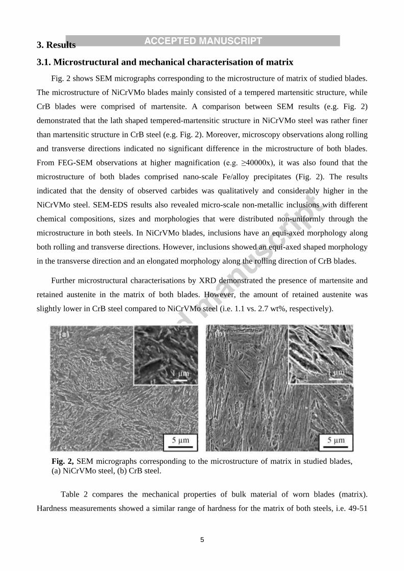
Fig. 2 shows SEM micrographs corresponding to the microstructure of matrix of studied blades.
The microstructure of NiCrVMo blades mainly consisted of a tempered martensitic structure, while
CrB blades were comprised of martensite. A comparison between SEM results (e.g. Fig. 2)
demonstrated that the lath shaped tempered-martensitic structure in NiCrVMo steel was rather finer
than martensitic structure in CrB steel (e.g. Fig. 2). Moreover, microscopy observations along rolling
and transverse directions indicated no significant difference in the microstructure of both blades.
From FEG-SEM observations at higher magnification (e.g. ≥40000x), it was also found that the
microstructure of both blades comprised nano-scale Fe/alloy precipitates (Fig. 2). The results
indicated that the density of observed carbides was qualitatively and considerably higher in the
NiCrVMo steel. SEM-EDS results also revealed micro-scale non-metallic inclusions with different
chemical compositions, sizes and morphologies that were distributed non-uniformly through the
microstructure in both steels. In NiCrVMo blades, inclusions have an equi-axed morphology along
both rolling and transverse directions. However, inclusions showed an equi-axed shaped morphology
in the transverse direction and an elongated morphology along the rolling direction of CrB blades.
Further microstructural characterisations by XRD demonstrated the presence of martensite and
retained austenite in the matrix of both blades. However, the amount of retained austenite was
slightly lower in CrB steel compared to NiCrVMo steel (i.e. 1.1 vs. 2.7 wt%, respectively).
Table 2 compares the mechanical properties of bulk material of worn blades (matrix).
Hardness measurements showed a similar range of hardness for the matrix of both steels, i.e. 49-51
Fig. 2, SEM micrographs corresponding to the microstructure of matrix in studied blades,
(a) NiCrVMo steel, (b) CrB steel.
6
HRC. Furthermore, the results showed a higher toughness in CrB steel compared to NiCrVMo steel
which can be mainly attributed to the effect of microstructure and chemical composition, especially
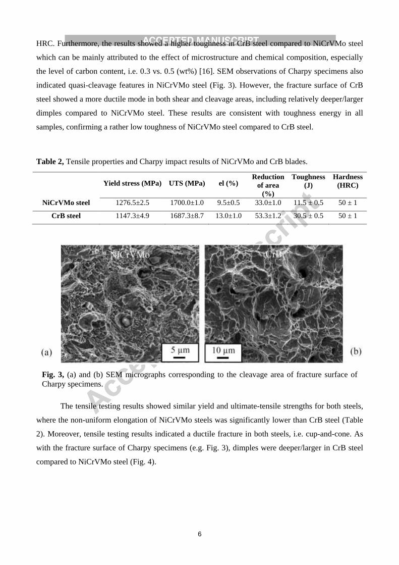
the level of carbon content, i.e. 0.3 vs. 0.5 (wt%) [16]. SEM observations of Charpy specimens also
indicated quasi-cleavage features in NiCrVMo steel (Fig. 3). However, the fracture surface of CrB
steel showed a more ductile mode in both shear and cleavage areas, including relatively deeper/larger
dimples compared to NiCrVMo steel. These results are consistent with toughness energy in all
samples, confirming a rather low toughness of NiCrVMo steel compared to CrB steel.
Table 2, Tensile properties and Charpy impact results of NiCrVMo and CrB blades.
Yield stress (MPa) UTS (MPa) el (%)
Reduction
of area
(%)
Toughness
(J)
Hardness
(HRC)
NiCrVMo steel 1276.5±2.5 1700.0±1.0 9.5±0.5 33.0±1.0 11.5 ± 0.5 50 ± 1
CrB steel 1147.3±4.9 1687.3±8.7 13.0±1.0 53.3±1.2 30.5 ± 0.5 50 ± 1
The tensile testing results showed similar yield and ultimate-tensile strengths for both steels,
where the non-uniform elongation of NiCrVMo steels was significantly lower than CrB steel (Table
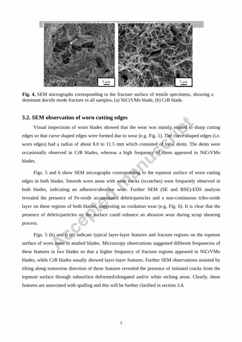
2). Moreover, tensile testing results indicated a ductile fracture in both steels, i.e. cup-and-cone. As
with the fracture surface of Charpy specimens (e.g. Fig. 3), dimples were deeper/larger in CrB steel
compared to NiCrVMo steel (Fig. 4).
Fig. 3, (a) and (b) SEM micrographs corresponding to the cleavage area of fracture surface of
Charpy specimens.
7
3.2. SEM observation of worn cutting edges
Visual inspections of worn blades showed that the wear was mainly related to sharp cutting
edges so that curve shaped edges were formed due to wear (e.g. Fig. 1). The curve shaped edges (i.e.
worn edges) had a radius of about 8.0 to 11.5 mm which consisted of local dents. The dents were
occasionally observed in CrB blades, whereas a high frequency of them appeared in NiCrVMo
blades.
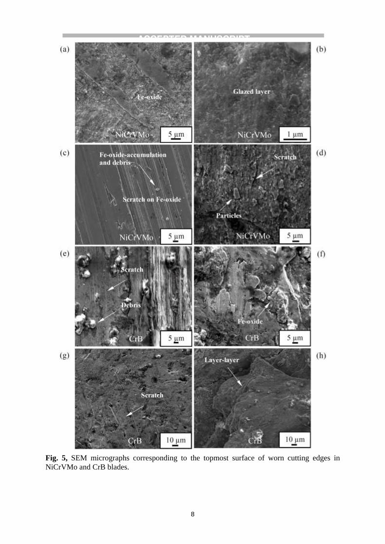
Figs. 5 and 6 show SEM micrographs corresponding to the topmost surface of worn cutting
edges in both blades. Smooth worn areas with wear tracks (scratches) were frequently observed in
both blades, indicating an adhesive/abrasive wear. Further SEM (SE and BSE)-EDS analysis
revealed the presence of Fe-oxide accumulated debris/particles and a non-continuous tribo-oxide
layer on these regions of both blades, suggesting an oxidation wear (e.g. Fig. 6). It is clear that the
presence of debris/particles on the surface could enhance an abrasion wear during scrap shearing
process.
Figs. 5 (h) and 6 (e) indicate typical layer-layer features and fracture regions on the topmost
surface of worn areas in studied blades. Microscopy observations suggested different frequencies of
these features in two blades so that a higher frequency of fracture regions appeared in NiCrVMo
blades, while CrB blades usually showed layer-layer features. Further SEM observations assisted by
tilting along transverse direction of these features revealed the presence of initiated cracks from the
topmost surface through subsurface deformed/elongated and/or white etching areas. Clearly, these
features are associated with spalling and this will be further clarified in section 3.4.
Fig. 4, SEM micrographs corresponding to the fracture surface of tensile specimens, showing a
dominant ductile mode fracture in all samples, (a) NiCrVMo blade, (b) CrB blade.
8
Fig. 5, SEM micrographs corresponding to the topmost surface of worn cutting edges in
NiCrVMo and CrB blades.

9
Fig. 6, SEM micrographs corresponding to the top surface of worn cutting edges, (a) to (d) BSE
images, (e) Selected SE images and corresponding EDS map, showing the presence of oxygen rich
areas (NiCrVMo blade).

10
3.3. XRD analysis of topmost surface of worn cutting edges
From the XRD spectra of both blades, two main phases were identified in worn areas which are
martensite (with a BCC crystal structure [17]) and retained austenite (with a FCC crystal structure),
e.g. Fig. 7. It should be noted that the peak shifting in the obtained spectra from the topmost surface
was primarily attributed to residual stresses in worn surfaces. In fact, surface deformations due to
wear resulted in residual stresses, though this was not studied as it was out of the scope of this
research.
The 2theta-XRD analysis revealed different amounts of retained austenite in the topmost surface
of worn cutting edges (round shaped) and matrix of NiCrVMo blades, while the level of retained
austenite was negligible in both regions of CrB blades (Table 3). Further XRD analysis of dent
shaped worn areas of both blades also showed a considerable higher amount of retained austenite
only in NiCrVMo blades.
GI-XRD analysis successfully indicated the presence of retained austenite at worn surfaces of
only NiCrVMo blades (Fig. 7). A comparison between the GI-XRD analysis of worn cutting edges
with a dent shaped and round shaped regions showed a higher amount of retained austenite in the
former regions (Table 3). These results indicated a wear induced phase transformation which could
subsequently increase the retained austenite on the surface of worn edges in NiCrVMo blades. From
the GI-XRD analysis of both blades, it was also found that Fe-oxides (i.e. FeO, Fe2O3 and Fe3O4)
were formed during wear, though the type of oxides was different in two studied blades (Fig. 7).
Table 3, The amount of retained austenite (wt%) determined by the XRD.
XRD
method CrB - blade NiCrVMo - blade
Top surface
(dent area)
Top surface
(round edge) Matrix
Top surface
(dent areas)
Top surface
(round edge) Matrix
2 theta Less than one Less than one 1.1 9.7 Less than one 2.7
Grazing
incidence Less than one Less than one Not applied 10.5 3.6 Not applied

11
3.4. SEM analysis of cross-sectional areas of worn cutting edges
In Fig. 8, a few selected SEM cross-sectional images show typical damages at the surface
layers of worn blades. Both examined blades showed a plastically deformed/elongated layer on the
worn surface. The microscopy observations indicated that this layer is non-continuous so that they
were appeared locally at different regions of samples. However, the results suggested a larger
frequency of these areas at worn cutting edges of CrB blades compared to NiCrVMo blades.
White etching layers/areas were not only found on the worn cutting edge surface, but also in
subsurface regions (Figs. 8 and 9). Nevertheless, white etching areas on the worn cutting edge
surface and subsurface were hardly observed in CrB blades, while they frequently appeared in
NiCrVMo blades, especially in subsurface areas (e.g. at a depth of about 200 µm beneath the worn
blade surface). In many places, the white etching layers were found to co-exist with parallel or
inclined cracks that these cracks are associated with surface spalling. Such spalling within the depth
of white-etching layer is shown broadly in Figs. 8 (a), and more precisely in Fig. 9, where the
thickness of spalling particles is in sub-mm scale.
Further FEG-SEM observations of the white etching areas at high magnifications evidenced an
ultra-fine ferritic/martensitic structure bands with a small amount of nano-scale bright features (Fig.
9 (e)). SEM-EDS analyses of these areas showed no chemical composition variation compared with
Fig. 7, XRD spectra (2theta and grazing incidence methods), showing peaks corresponding to
ferrite and retained austenite in the matrix and worn cutting edges of NiCrVMo and CrB
blades.

12
the matrix. These results are in agreement with the findings of other researchers who also reported a
similar structure for white etching areas in steels [18,19].
SEM observations also showed arrested cracks in the NiCrVMo steel matrix that had been
deflected from subsurface white etching areas (Fig. 9 (d)). It is evident that white etching areas with
a thickness of about 10-30 µm precede crack initiation and propagation. Additionally, microscopy
analysis did not demonstrate a considerable growth and coalescence of such cracks through the
matrix. It is clear that the tempered martensite matrix of NiCrVMo-steel blades could effectively
retard crack propagation during wear.

13
Fig. 8, SEM micrographs, showing tribolayer and elongated/deformed areas below worn
cutting edges, (a) to (d) NiCrVMo blade, (e) and (f) CrB blade.

14
Fig. 10 shows cracks almost perpendicular to the worn surface that have penetrated deeply up
to several millimetres (e.g. 1 to 3 mm) into both blades. These cracks were mainly initiated from
Fig. 9, (a) Optical micrograph of an etched sample, showing the presence of subsurface white etching
areas in a NiCrVMo blade, (b) to (e) SEM micrographs corresponding to the white etching area in
(a).

15
severely deformed areas or white etching layers that could have led to the generation of spalling and
delamination wear particles. Some cracks were even opened to have some external solids inserted
inside. Such cracks could have been produced after the blade was repeatedly subjected to severe
impact loads. Further microhardness measurements indicated that the surrounded regions of crack
tips had a lower hardness compared with the matrix (e.g. ~46 HRC). However, comparative SEM-
EDS analysis of these areas and matrix did not show any significant difference in their
microstructure and chemical composition.
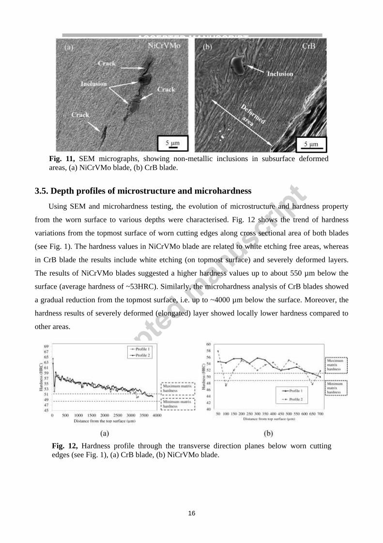
The behaviour of non-metallic inclusions in the wear failure was also examined carefully. Two
typical cross-sectional micrographs containing such inclusions are shown in Fig. 11, exhibiting the
presence of inclusions in deformed areas just below worn surface. The inclusion in Fig. 11 (a) has
been determined to be rich in Mn-S-V using SEM-EDS. Several short cracks were found both inside
the inclusion and along its boundary to the matrix. The cracks were enveloped inside the inclusion
itself, i.e. without any lateral propagation into the adjacent matrix. This behaviour was observed in
almost all of inclusions regardless their morphology and size in NiCrVMo blades. It has been
established in the literature that large and incoherent particles/inclusions necessitate a lower amount
of subsurface deformation for crack initiation [20,21,22,23]. However, SEM analysis rarely showed
initiated cracks from inclusions in CrB blades (e.g. Fig. 11 (b)).
Fig. 10, SEM micrographs corresponding to worn areas, showing propagated cracks from
deformed and white etching areas through the material.
16
3.5. Depth profiles of microstructure and microhardness
Using SEM and microhardness testing, the evolution of microstructure and hardness property
from the worn surface to various depths were characterised. Fig. 12 shows the trend of hardness
variations from the topmost surface of worn cutting edges along cross sectional area of both blades
(see Fig. 1). The hardness values in NiCrVMo blade are related to white etching free areas, whereas
in CrB blade the results include white etching (on topmost surface) and severely deformed layers.
The results of NiCrVMo blades suggested a higher hardness values up to about 550 µm below the
surface (average hardness of ~53HRC). Similarly, the microhardness analysis of CrB blades showed
a gradual reduction from the topmost surface, i.e. up to ~4000 µm below the surface. Moreover, the
hardness results of severely deformed (elongated) layer showed locally lower hardness compared to
other areas.
Fig. 11, SEM micrographs, showing non-metallic inclusions in subsurface deformed
areas, (a) NiCrVMo blade, (b) CrB blade.
Fig. 12, Hardness profile through the transverse direction planes below worn cutting
edges (see Fig. 1), (a) CrB blade, (b) NiCrVMo blade.

17
Fig. 13 shows selected SEM images taken at various depths (from a worn surface) of the
NiCrVMo and CrB worn blade samples. The plastic deformation has been found to be non-uniform
so that most of the imaged areas exhibit preferentially elongated microstructure along the orientation
of the worn surface, whereas the less- or non-deformed structures appear in a few islands in deeper
areas. The relative fraction of elongated region and its continuity increase towards the worn surface
before entering the top layer of severely deformed microstructure. In the SEM imaged area, such
deformed layer exhibited a thickness of maximum ~100 µm, e.g. Figs. 13 (b) and (d). In the top
layer, the entire volume shows a fibre-like microstructure with its elongation parallel to the worn
surface. Note that most delamination cracks have been found to generate in such elongated layers,
like the one shown in Fig. 8 (f). When the elongated layer was imaged at the best resolution of the
FEG-SEM (Figs. 13 (a) and (b)), one can find that the microstructure has been completely replaced
by the fibre-like distribution of extremely fine grains. In particular, most of the carbide precipitates
exhibit nodular shape and sizes in nano scale. Moreover, microstructural observations and
microhardness profiles below the elongated layer suggested that a steady state compressive
deformation occurred and the hardness of both steels gradually decreased with distance increases
from the topmost surface (Figs. 13 (c) and (f)).
Fig. 13, Selected SEM micrographs, showing the variation of microstructure at different
depths below the topmost worn surface, (a) to (c) NiCrVMo blade, (d) to (f) CrB blade.

18
Microhardness measurements of surface/subsurface white etching areas showed a hardness of
~30 to 75% higher than the tempered-martensite matrix in NiCrVMo blades (i.e. ~65 to 88 HRC)
(e.g. Fig. 14). Similarly, the hardness of white etching areas in CrB blade was ~25% higher than the
martensitic matrix (i.e. ~62 to 65 HRC).
4. Discussion
4.1. Wear mechanisms of shear blades
The wear mechanisms of the blades investigated have been found to include progressive wear
by means of abrasive wear, adhesive wear and tribo-oxidation, and surface spalling featured with
deformation/delamination, white etching layer and crack propagation.
The adhesive wear is featured with a material transfer and subsequent shearing off during
adhesive contacts which forms scale like topography on the fracture surface [24]. The reason to
consider adhesive wear as a major progressive wear mechanism has been based on the description of
the end-user that the blades were used in cutting steel-based scraps. In such a working circumstance,
the cutting process would have involved a severe steel-to-steel sliding contact. Such a contact is
known to be strongly adhesive, although the current SEM observations failed to find any typical
fresh feature of adhesive wear. However, adhesive sliding wear is known to exhibit severe friction
which triggers extensive plastic deformation of the top worn surface. Interestingly, such plastically
deformed worn surfaces were found in almost all the observed cross-sectional samples, Fig. 8.
Oxidation wear is featured with the presence of Fe-oxide debris/layer on worn surfaces. SEM
analysis of topmost surface of both blades demonstrated Fe-oxide layer on worn surfaces which
suggested the possible frictional temperature rises during shearing process (Figs. 5 and 6). The
oxidation wear is more pronounced in the NiCrVMo blade, on which GI-XRD analysis of the worn
cutting edge has detected both magnetite (Fe3O4) and wustite (FeO) whereas such oxides were not
Fig. 14, Selected optical micrograph, showing the position of Knoop-microhardness
indentations in a subsurface white etching area in the NiCrVMo blade.

19
detected on the worn edge of CrB blade (Fig. 7). It is thought that the oxide was mainly formed due
to mutual interaction between blade surface and scraps. In fact, interfacial temperature rises due to
frictional heat increased the temperature over the flash temperature, especially in asperity contacts
[25,26,27,28]. A high temperature in addition to ambient humidity could enhance the oxide
formation on the surface. The asperities were smeared and debris was formed during initial stage of
impact/sliding wear by abrasion or adhesive spalling of mating surface asperities [29,30]. However,
an abrasion due to sliding or rubbing the trapped debris or detached wear particles (e.g. hard oxides)
between contact surfaces scratched and ploughed grooves on the worn surfaces (Fig. 5) [27,31].
SEM analysis showed the presence of fracture surfaces and cracks in different features on the
topmost surface and subsurface areas of worn cutting edges (e.g. Figs. 5, 6 and 8). These results
demonstrated three types of spalling in two studied blades which could differently and considerably
remove the material from the surface of cutting edges.
The first type of spalling took place within the depths of severely deformed layer (e.g. Fig. 8
(f)). In fact, shear deformation increases due to wear is accompanied by a dislocation pile-up in the
subsurface [32]. Therefore, further sliding of mating surfaces likely caused a micro-crack initiation
and propagation under a combined tensile and shear mode in deformed regions until the final fracture
[33]. It has been also reported that cracks can be formed under impact loadings in subsurface features
of worn surfaces [34]. A cyclic loading at high strain amplitudes on contact areas of cutting edges
during shearing process could lead to surface fracture. It can be thus inferred that the surface spalling
due to delamination wear could primarily result from repetitive sliding/impact loadings during
shearing process.
The second type of spalling happened due to the formation of white etching bands, where the
white etching bands could be either in the outmost worn surface (e.g. Fig. 8 (a)) or in the subsurface
(Fig. 9). As pointed out earlier in section 3.5, these regions have a considerably higher hardness
compared to the matrix. The observed difference between the hardness of matrix and white etching
areas leads to a higher stress concentration in these areas. Presumably, a repeatedly striking/sliding
during shearing process could result in crack initiation and propagation and consequently cause
surface spalling. Our results evidenced the presence of cracks through subsurface white etching areas
demonstrated that this mechanism significantly contributed in the formation of deep cracks and
consequently material removal, especially in NiCrVMo blades. It is thus clear that the material
removal from surface was considerably accelerated by white etching areas. Similarly, Zhang et al.
showed that surface and subsurface white etching areas in a tempered-martensitic structure of low

20
alloy steels dominantly act as nucleation sites for crack initiation during impact wear [19]. They
showed that this mechanism can remarkably reduce the wear resistance.
The third type of spalling was caused by deep cracks almost normal to the outermost surface
of worn cutting edges, frequently surrounded by a relatively lower hardness region (Fig. 10). These
cracks were mainly initiated from severely deformed layers or surface white etching areas. It is
thought that localised deformations and frictional temperature increases might soften the material
which encouraged the crack tip growth through materials [35]. However, these cracks could result in
large wear particles and left macro-scale dents on the worn cutting edge.
Small propagated cracks from interfaces of non-metallic inclusions through the matrix were
extensively observed only in NiCrVMo blades. In fact, mobile dislocations generated by the applied
loads during shearing process can be blocked and piled up by inclusions [20,36,37]. Presumably, this
is stronger than the cohesive strength of matrix and inclusion, and could enhance void/crack
formations. Although there is no available data on the coherency of inclusions in this study, it is
thought that the stronger cohesion between inclusions and matrix was likely the reason for the
absence of cracks in CrB blades. Cracks were also observed through inclusions (e.g. V-Mn-S rich
inclusions) in NiCrVMo blades (e.g. Fig. 11 (a)). Perhaps dislocation pile-up stresses can break hard
particles which form small cracks [37]. However, our results did not show any large propagated
cracks inside the matrix, suggesting that non-metallic inclusions did not contribute to wear in studied
blades.
4.2. Subsurface microstructure evolution
As mentioned earlier, NiCrVMo blades and CrB blades are used to cut metal scrap with a
hardness of less than steel shear blades. This means that the loading conditions are ideally in an
elastic regime for blades. However, in actual conditions a complex stressing condition applies on
cutting edges during shearing process which can be influenced by many factors such as interaction
areas, strain rate and friction. Additionally, the observed wear mechanisms in two studied blades,
with the same average hardness, indicated that the wear performance depends upon a wide range of
mechanical properties of materials [38,39]. Therefore, shearing process conditions and the
mechanical properties of blades are taken into consideration to explain the reasons for
surface/subsurface microstructural evolutions.
The severely deformed layers indicate that, as a result of strong mechanical loads, the
surfaces of cutting edges have completely lost their original hardened microstructure of as-quenched
or tempered martensite. For the NiCrVMo steel, the deformed layer showed not only extremely

21
elongated fine ferritic matrix, but also further nodularised carbide particles as compared to those in
the tempered martensite. Consequently, the hardness property of the deformed layer was found to be
different from the bulk metal. In particular, the two blades showed different subsurface hardness
profiles (Fig. 12). For the CrB blade, a linear increase of hardness was measured from the bulk steel
to the worn surface, reaching a maximum hardness of about 65 HRC. Such hardness profile indicates
predominantly the deformation induced work hardening [40,41]. On the other hand, the NiCrVMo
blade did not show a deformed top surface as hard as the CrB blade. Instead, the hardness profile
reached a relatively stabilised range of values along with the elongated microstructure, which may
imply the combined effects of both work hardening and deformation induced softening. Because
most energy spent in the plastic deformation is known to convert to thermal energy, such softening
can be explained by an in-situ self-recovery of the work hardened microstructure.
The microscopy observation also showed a higher frequency of deformed/elongated areas in
CrB blades compared to NiCrVMo blades. A possible explanation for the different frequencies of
deformed areas in two studied blades is inferred by taking into account the microscopy observations
and microhardness analysis. The most likely reason is related to the effect of frictional temperature
rises on the softening of surface areas [26,42]. Although local temperature rises in worn areas of
studied steels are difficult to estimate, but this phenomenon is not outside the realm of possibility. It
is thus clear that a probable thermal softening due to frictional temperature rises could encourage
local deformations during wear. However, in NiCrVMo steel, a rather finer tempered-martensitic
structure, solid solution strengthening and a high density of Fe/alloy carbides retarded the possible
softening [10,43,44,45]. Previous studies have shown that CrB-steel have a lower temper softening
resistance, especially at temperatures over 300 °C compared to NiCrVMo steel [46]. Similarly, other
researchers have reported that frictional temperature rises in steel sliding over steel can reach even
over 1000 °C [25,47, 48]. It has been shown that over a critical temperature due to wear the material
can be temper softened, while below this range a work hardening occurs. This is consistent with our
conclusions, suggesting that frictional heating during shearing might locally soften the surface of
steels and a temperature gradient enhanced subsurface deformations [11,44,48].
The two blades behaved differently in the white etching layers/areas. The CrB blade formed
white etching layers mostly in the surface deformed layer, whereas the NiCrVMo blade formed such
layers not only on the surface but also in subsurface regions (Figs. 8 and 9). Different mechanisms
have been suggested in the literature for the formation of white etching areas. White etching areas
are generally formed due to friction and localised severe deformations during sliding/impact wear
[18,49,50]. Such a localised energy conversion can be used to explain the formation of the white
22
etching layers. It is known that the maximum shear loads would be on the contact surface if the
actual friction coefficient is high enough which consequently resulted in the surface deformed layer.
If the plastic deformation took place in such an extremely high rate that the converted thermal energy
did not have enough time to spread to the nearby volume, depending on the thermal conduction
coefficient, the localised temperature would be high enough to enforce a phase transformation from
martensite or ferrite to austenite [51]. Then subsequent cooling of the austenite would lead to the
formation of a mixture of fine martensite and retained austenite [52]. In current work, the XRD
analysis of NiCrVMo blades also confirmed the increased fraction of austenite in worn cutting edges
as compared to the bulk blade (Table 3). It is clear that a localised severe deformation occurred due
to extremely high compressive and shear loads in their service conditions that could increase the
temperature up to austenite formation temperature. Other researchers also studied the austenite
formation during wear [26,53]. Similarly, they reported that the austenite can be formed during wear
by a rapid austenitisation in worn areas so that the amount of retained austenite can be changed
during subsequent cooling.
Moreover, the formation of white etching layers at certain depths below the surface suggested
a mechanism that could enhance a subsurface severe localised deformation (Fig. 9). Such behaviour
reflects the applied loading circumstances. In fact, worn edges was subjected to repeated impact and
compressive loads so that the blade exhibited low rate of progressive wear caused by abrasive and
adhesive wear. As a result, a maximum shear stress was caused at a certain depth for a period of
repeated loading. In other words, repeated strong impacting is a major loading characteristic. Also,
the lower toughness of NiCrVMo steel (i.e. ~10J) during high strain impact/compressive loading
conditions could enhance localised severe deformations along shear bands, resulted in subsurface
white etching layers formation [54]. This is in agreement with the findings of other researchers who
also reported that white etching layers can be extensively formed in low toughness tempered-
martensite steels during dynamic compressive deformations [55]. They showed that a lower absorbed
compressive deformation could be responsible for the formation of white etching (adiabatic shear)
layers.
5. Conclusions
An investigation was performed into NiCrVMo-steel (tempered-martensitic structure) and CrB-
steel (martensitic structure) worn scrap shear blades to better understand their wear mechanisms
under service conditions. The following concluding remarks can be made:
1. In studied blades, the observed wear mechanisms were mainly categorised in progressive and
spalling wear.
23
2. The results suggested a progressive wear due to abrasive, adhesive and oxidation wear in
both NiCrVMo and CrB blades.
3. Spalling due to delamination wear from severely deformed subsurface areas and crack
propagation in CrB blades was the dominant severe wear mechanism. In NiCrVMo blades,
spalling and crack propagation from surface and subsurface white etching layers were mainly
responsible for the severe wear.
4. Within subsurface deformed regions, non-metallic inclusions were observed in both
NiCrVMo and CrB blades. Nevertheless, the results showed that inclusions did not contribute
to the wear of both blades during shearing process.
Acknowledgments
The authors would like to acknowledge the sponsorship provided by Innovate UK through the
Knowledge Transfer Partnership programme (KTP010269 Sheffield Hallam University & Tyzack
Machine Knives ltd.).
References
[1] R.Neugebauer, et al., "Velocity Effects in Metal Forming and Machining Processes," CIRP Annals - Manufacturing
Technology, vol. 60, p. 627–650, 2011.
[2] E.O.Ezugwu, Z.M.Wang, and A.R.Machado, "The Machinability of Nickel-based Alloys: A Review," Journal of
Materials Processing Technology, vol. 86, pp. 1-16, 1999.
[3] E.O.Ezugwu, J.Bonney, and Y.Yamane, "An Overview of the Machinability of Aeroengine Alloys," Journal of
Materials Processing Technology, vol. 134, pp. 233-253, 2003.
[4] P.L.Hurricks, "Some Metallurgical Factors Controlling the Adhesive and Abrasive Wear Resistance of Steels. A
Review," Wear, vol. 26, pp. 285-304, 1973.
[5] D.Son, et al., "Analysis of the Failures on Shear Cutting Blades after Trimming of Ultra High Strength Steel,"
Engineering Failure Analysis, vol. 71, pp. 148-156, 2017.
[6] G.Krauss, "Deformation and Fracture in Martensitic Carbon Steels Tempered at Low Temperatures," Metallurgical
and Materials Transactions A, vol. 32A, pp. 861-877, 2001.
[7] G.Krauss, "Martensite in Steel: Strength and Structure," Materials Science and Engineering A, vol. 273–275, pp. 40-
57, 1999.
[8] S.Morito, H.Tanaka, R.Konishi, T.Furuhara, and T.Maki, "The Morphology and Crystallography of Lath Martensite
in Fe-C Alloys," Acta Materialia, vol. 51, pp. 1789-1799, 2003.
[9] Y.Tomita, "Development of Fracture Toughness of Ultrahigh Strength, Medium Carbon, Low Alloy Steels for
Aerospace Applications," International Materials Reviews, vol. 45, no. 1, pp. 27-37, 2000.
[10] T.Takayama and Ch.Nakao, "High Toughness Wear Resistant Steel," Japanese Patent US6899774B2, May 31,
2005.

24
[11] Y.Wang, T.Lei, and J.Liu, "Tribo-metallographic Behavior of High Carbon Steels in Dry Sliding II. Microstructure
and Wear," Wear, vol. 231, pp. 12-19, 1999.
[12] P.Clayton, K.J.Sawley, P.J.Bolton, and G.M.Pell, "Wear Behavior of Bainitic Steels," Wear, vol. 120, pp. 199-220,
1987.
[13] A.A.Torrance, "The Metallography of Worn Surfaces and Some Theories of Wear," Wear, vol. 50, pp. 169-182,
1978.
[14] T.Takayama, "High Hardness, High Toughness Steels and Crawler Components, Earth Wear Resistant Components,
Fastening Bolts, High Toughness Gears, High Toughness, High Contact Pressure Resistance Gears, and Wear
Resistant Steel Plates Using the Same ," Japanese Patent US20040047757A1, Mar. 11, 2004.
[15] D.G.Bruce, "Method of Heat Treating Cultivating Disc, Coulter, and Seed Drill Blades Made from Heat Quenched
Boron Steels, Such That They Can Be Roller Re-edged and Re-sharpened, and Yet Retain Excellent Toughness,
Hardness and Wear Characteristics, and Are Especiall," USA Patent US7905968B2, Mar. 15, 2011.
[16] F.Zia-Ebrahimp and G.Krauss, "Mechanisms of Tempered Martensite Embrittlement in Medium Carbon Steels,"
Acta Metallurgica, vol. 32, no. 10, pp. 1767-1778, 1984.
[17] B.Hutchinson, et al., "Microstructures and hardness of as-quenched martensites (0.1–0.5%C)," Acta Materialia , vol.
59, p. 5845–5858, 2011.
[18] M.H.Evans, "An Updated Review: White Etching Cracks (WECs) and Axial Cracks in Wind Turbine Gearbox
Bearings," Materials Science and Technology, pp. 1-37, 2015.
[19] B.Zhang, et al., "A Study on the Behavior of Adiabatic Shear Bands in Impact Wear," Wear, vol. 198, pp. 287-292,
1996.
[20] N.Saka, J.J.Pamies-Teixeira, and N.P.Suh, "Wear of Two-Phase Metals," Wear, vol. 44, pp. 77-86, 1977.
[21] Y.P.Zeng, H.M.Fan, and X.Sh.Xie, "Effects of the Shape and Size of Rectangular Inclusions on the Fatigue
Cracking Behavior of Ultra-high Strength Steels," International Journal of Minerals, Metallurgy and Materials, vol.
20, no. 4, pp. 360-364, 2013.
[22] D.Spriestersbach, P.Grad, and E.Kerscher, "Influence of Different Non-metallic Inclusion Types on the Crack
Initiation in High-strength Seels in the VHCF Regime," International Journal of Fatigue, vol. 64, p. 114–120, 2014.
[23] S.Jahanmir and N.P.Suh, "Mechanics of Subsurface Void Nucleation in Delamination Wear," Wear, vol. 44, pp. 17-
38, 1977.
[24] S.Hogmark, 0.Vingsbo, and S.Fridstrom, "Mechanisms of Dry Wear of Some Martensitic Steels," Wear, vol. 31, pp.
39-61, 1975.
[25] W.M.Rainforth, R.Stevens, and J.Nutting, "Deformation Structures Induced by Sliding Contact," Philosophical
Magazine A, vol. 66, no. 4, pp. 621-641, 1992.
[26] Y.Wang, T.Lei, and J.Liu, "Tribo-metallographic Behavior of High Carbon Steels in Dry Sliding III. Dynamic
Microstructural Changes and Wear," Wear, vol. 231, pp. 20-37, 1999.
[27] F.H.Stott, "The Role of Oxidation in the Wear of Alloys," Tribology International, vol. 31, no. 1-3, pp. 61-71, 1998.
[28] B.Pujilaksono, T.Jonsson, M.Halvarsson, J.E.Svensson, and L.G.Johansson, "Oxidation of Iron at 400-600C in Dry
and Wet O2," Corrosion Science, vol. 52, pp. 1560-1569, 2010.
[29] S.Jahanmir, N.P.Suh, and E.P.Abrahamson, "The Delamination Theory of Wear and the Wear of a Composite
Surface," Wear, vol. 32, pp. 33-49, 1975.

25
[30] N.Saka, A.M.Eleiche, and N.P.Suh, "Wear of Metals at High Sliding Speeds," Wear, vol. 44, pp. 109-125, 1977.
[31] Z.Gronostajski, M.Kaszuba, M.Hawryluk, and M.Zwierzchowski, "A Review of the Degradation Mechanisms of the
Hot Forging Tools," Archives of Civil and Mechanical Engineering , vol. 14, pp. 528-539, 2014.
[32] N.P.Suh, "An Overview of the Delamination Theory of Wear," Wear, vol. 44, pp. 1-16, 1977.
[33] k.Kato and K.Adachi, "Wear Mechanisms," in Modern Tribology Handbook, Principles of Tribology, B.Bhushan,
Ed. CRC Press, 2001, vol. One, pp. 273-299.
[34] M.Lindroos, et al., "The Effect of Impact Conditions on the Wear and Deformation Behavior of Wear Resistant
Steels," Wear, vol. 328-329, p. 197–205, 2015.
[35] J.R.Fleming and N.P.Suh, "The Relationship between Crack Propagation Rates and Wear Rates," Wear, vol. 44, pp.
57-64, 1977.
[36] N.P.Suh, "The Delamination Theory of Wear," Wear, vol. 25, pp. 111-124, 1973.
[37] R.D.K.Misra, G.C.Weatherly, J.E.Hartmann, and A.J.Boucek, "Ultrahigh Strength Hot Rolled Microalloyed Steels:
Microstructural Aspects of Development," Materials Science and Technology, vol. 17, pp. 1119-1129, 2001.
[38] J.F.Archard, "Contact and Rubbing of Flat Surfaces," Journal of Applied Physics, vol. 24, no. 8, pp. 981-988, 1953.
[39] E.Hornbogen, "The Role of Fracture Toughness in the Wear of Metals," Wear, vol. 33, pp. 251-259, 1975.
[40] J.E.Hockett and O.D.Sherby, "Large Strain Deformation of Poly Crystalline Metals at Low Homologous
Temperatures," Journal of Mech. Phys. Solids, vol. 23, pp. 87-98, 1975.
[41] A.T.Alpas, H.Hu, and J.Zhang, "Plastic Deformation and Damage Accumulation Below the Worn Surfaces," Wear,
vol. 162-164, pp. 188-195, 1993.
[42] T.Takayama, "Rolling Element and Method of Producing the Same," Japanese Patent US7691212B2, Apr. 6, 2010.
[43] W.Barrois, "Repeated Plastic Deformation as a Cause of Mechanical Surface Damage in Fatigue, Wear, Fretting-
Fatigue, and Rolling Fatigue," International Journal of Fatigue, vol. 1, no. 4, pp. 167-189, 1979.
[44] H.Chai and C.Laird, "Mechanisms of Cyclic Softening and Cyclic Creep in Low Carbon Steel," Materials Science
and Engineering, vol. 93, pp. 159-174, 1987.
[45] M.R.Green, W.M.Rainforth, M.F.Frolish, and J.H.Beynon, "The Effect of Microstructure and Composition on the
Rolling Contact Fatigue Behaviour of Cast Bainitic Steels," Wear, vol. 263, p. 756–765, 2007.
[46] E.Abbasi, "Tempering of CrB, NiCrMo and NiCrVMo Steels," Sheffield Hallam University and Tyzack Machine
Knives, Internal Technical Report KTP-P004, 2017.
[47] F.Katsuki, "Subsurface Characteristics of a Fe–0.4 wt%C Martenstic Steel Abraded with Nano Indentation and
Cross-sectional TEM Techniques," Wear, vol. 303, pp. 92-97, 2013.
[48] Y.Wang, T.Lei, and J.Liu, "Tribo-metallographic Behavior of High Carbon Steels in Dry Sliding I. Wear
Mechanisms and Their Transition," Wear, vol. 231, pp. 1-11, 1999.
[49] K.M.Roessig and J.J.Mason, "Adiabatic Shear Localization in the Impact of Edge-notched Specimens,"
Experimental Mechanics, vol. 38, no. 3, pp. 196-203, 1998.
[50] Y.Y.Yang, H.Sh.Fang, Y.K.Zheng, Zh.G.Yang, and Zh.L.Jiang, "The Failure Models Induced by White Layers
During Impact Wear," Wear, vol. 185, pp. 17-22, 1995.
[51] A.Medvedeva, J.Bergstrom, S.Gunnarsson, P.Krakhmalev, and L.G.Nordh, "Influence of Nickel Content on
Machinability of a Hot-work Tool Steel in Prehardened Condition," Materials and Design , vol. 32, pp. 706-715,

26
2011.
[52] D.R.Lesuer, C.K.Syna, and O.D.Sherby, "Severe Plastic Deformation Through Adiabatic Shear Banding in Fe–C
Steels," Materials Science and Engineering A, vol. 410–411, p. 222–225, 2005.
[53] J.Hershberger, O.O.Ajayi, J.Zhang, H.Yoonb, and G.R.Fenske, "Formation of Austenite during Scuffing Failure of
SAE 4340 Steel," Wear, vol. 256, p. 159–167, 2004.
[54] A.Pineau, A.A.Benzerga, and T.Pardoen, "Failure of Metals I: Brittle and Ductile Fracture," Acta Materialia, vol.
107, pp. 424-483, 2016.
[55] H.Kim, J.Park, M.Kang, and S.Lee, "Interpretation of Charpy Impact Energy Characteristics by Microstructural
Evolution of Dynamically Compressed Specimens in Three Tempered Martensitic Steels," Materials Science and
Engineering A, vol. 649, pp. 57-67, 2016.
Highlights - The wear mechanisms were progressive wear and spalling wear in studied blades.
- Progressive wear occurred due to abrasive, adhesive and oxidation wear.
- Spalling wear was caused by delamination, white etching layers and crack propagation.
- Spalling wear was mainly responsible for the severe wear.
- Inclusions did not contribute to wear during shearing process in studied blades.