Embed Size (px)
Citation preview

CASE STUDY TO DETERMINE THE CAMBER OF POST-TENSIONED ‘ I ’ BEAM
LEE POH HUAT
UNIVERSITI TEKNOLOGI MALAYSIA


CASE STUDY TO DETERMINE THE CAMBER OF
POST- TENSIONED ‘I’ BEAM
LEE POH HUAT
A project report submitted in partial fulfilment of the
requirements for the award of the degree of
Master of Engineering ( Civil-Structure )
Faculty of Civil Engineering
Universiti Teknologi Malaysia
MARCH 2005


iii
To Elissa and Bryan
for your companionship, understanding and
continuous encouragement over the years.

iv
ACKNOWLEDGEMENT
I would like to thank Assoc. Prof. Dr. Wahid Omar for his guidance and advice
towards making this project a success. My sincere appreciation also goes to his
research team for their assistance in laboratory testing.
v
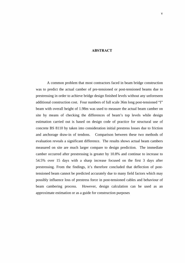
ABSTRACT
A common problem that most contractors faced in beam bridge construction
was to predict the actual camber of pre-tensioned or post-tensioned beams due to
prestressing in order to achieve bridge design finished levels without any unforeseen
additional construction cost. Four numbers of full scale 36m long post-tensioned “I”
beam with overall height of 1.98m was used to measure the actual beam camber on
site by means of checking the differences of beam’s top levels while design
estimation carried out is based on design code of practice for structural use of
concrete BS 8110 by taken into consideration initial prestress losses due to friction
and anchorage draw-in of tendons. Comparison between these two methods of
evaluation reveals a significant difference. The results shows actual beam cambers
measured on site are much larger compare to design prediction. The immediate
camber occurred after prestressing is greater by 10.8% and continue to increase to
54.5% over 15 days with a sharp increase focused on the first 3 days after
prestressing. From the findings, it’s therefore concluded that deflection of post-
tensioned beam cannot be predicted accurately due to many field factors which may
possibly influence loss of prestress force in post-tensioned cables and behaviour of
beam cambering process. However, design calculation can be used as an
approximate estimation or as a guide for construction purposes

vi
ABSTRAK
Suatu masalah umum yang sering dihadapi oleh kontraktor dalam kerja-kerja
pembinaan jambatan jenis rasuk pra-tegang atau pasca-tegang ialah usaha untuk
membuat anggaran nilai camber rasuk akibat daya mampatan dari tendon supaya
aras rekabentuk jambatan dapat dicapai tanpa perbelanjaan lebihan yang tidak
dijangka. Empat batang rasuk ‘I’ dengan panjang 36m serta tinggi 1.98m telah
digunakan dalam kajian ini bagi menentukan nilai camber sebenar di tapak secara
mengukur perbezaan aras atas rasuk. Pengiraan camber rasuk dibuat dengan
merujuk kepada BS 8110 dan mengambil kira nilai kehilangan daya tegangan akibat
geseran dan gelinciran tambat yang berlaku pada tendon. Perbandingan yang
dijalankan ke atas kedua-dua jenis cara penilaian ini menunjukkan suatu perbezaan
yang ketara dimana nilai camber sebenar yang diperolehi dari tapak mempunyai
nilai yang lebih besar berbanding dengan hasil dari pengiraan. Camber awal yang
diperolehi dari tapak mempunyai nilai lebihan sebanyak 10.8% pada permulaan dan
meningkat kepada 54.5% dalam masa 15 hari selepas rasuk ditegang. Peningkatan
nilai camber ini tertumpu kepada 3 hari yang pertama dengan nilai penambahan
yang besar. Dari keputusan kajian ini, dapat disimpulkan bahawa nilai camber tidak
dapat dianggarkan dengan mudah dan tepat disebabkan oleh beberapa faktor yang
wujud di tapak yang berkemungkinan dapat mempengaruhi hilangan daya tegangan
pada tendon serta proses pembentukan camber rasuk. Walau bagaimanapun,
pengiraan camber rasuk masih boleh digunakan sebagai anggaran kasar serta
panduan bagi tujuan pembinaan.
vii
TABLE OF CONTENTS
CHAPTER TITLE PAGE
1 Introduction 1
1.1 General 1
1.2 Problem Statement 2
1.3 Objective of Study 4
1.4 Scope of Study 4
2 Literature Review 6
2.1 Introduction 6
2.2 Materials for Prestressed Concrete 7
2.2.1 Concrete 7
2.2.2 Prestressing Reinforcement 8
2.2.3 Anchorage System and Equipment 9
2.3 Properties of Material for Prestressed Concrete 12
2.3.1 Strength of Concrete 12
2.3.2 Modulus of Elasticity of Concrete 13
2.3.3 Creep and Shrinkage of Concrete 14
2.3.4 Relaxation of Prestressing Steel 14
2.3.5 Corrosion and Deterioration of Strands 15
2.4 Prestressed Concrete 15
2.4.1 Advantage and Disadvantage of Prestressed Concrete 16
2.4.2 Prestressing System 17

viii
2.5 Partial Loss of Prestress Force 21
2.5.1 Elastic Shortening of Concrete 22
2.5.2 Friction Losses 23
2.5.3 Anchorage Draw-in 24
2.5.4 Concrete Shrinkage 26
2.5.5 Concrete Creep 27
2.5.6 Steel Relaxation 28
2.5.7 Total Prestress Losses 29
2.6 Deflection of Prestressed Concrete 29
2.6.1 Short-term Deflection of Uncracked Member 30
2.6.2 Long-term Deflection 32
2.6.3 Deflection of Cracked Member 33
2.7 Method of Construction for Post-tensioned Beam 35
2.7.1 Preparation of Base Form 35
2.7.2 Fixing of Reinforcement and Tendon 37
2.7.3 Erection of Steel Mould 38
2.7.4 Concreting of Beam 39
2.7.5 Stripping of Mould and Curing Concrete 41
2.7.6 Stressing and Grouting of Beam 41
3 Methodology 43
3.1 Introduction 43
3.2 Method of Measurement for Actual Beam Camber 44
3.3 Design Estimation for Beam Camber 47
3.4 Collection of Concrete Specimens 48
4 Results and Discussion 51
4.1 Introduction 51
4.2 Comparison of Beam Camber 52
4.3 Factors that Influence Beam Camber and
Prevention Method 54

ix
5 Conclusions and Recommendations 56
5.1 Conclusion 56
5.2 Recommendations for Future Study 57
References 58
Appendixes A - D 59 - 80
x
LIST OF TABLE
TABLE NO. TITLE PAGE
2.1 Comprehensive strength for prestressed concrete 7
3.1 Beam’s top levels surveyed from site 46

xi
LIST OF FIGURES
FIGURE NO. TITLE PAGE
1.1 Schematic illustration of beam camber for a 3 spans bridge 3
1.2 Typical detail for 36m post-tensioned beam 5
2.1 Types of anchorage system 11
2.2 Tangent and secant modulus of concrete 13
2.3 Pre-tensioning method 18
2.4 Post-tensioning method 20
2.5 Draw-in loss : Variation in applied prestress
force with friction 26
2.6 Relationship between tendon eccentricity and
prestress moment diagram 31
2.7 Coefficient K for various type of bending moment diagram 34
3.1 Timber base form & metal side form 37
3.2 Installation of reinforcement and tendon 38

xii
3.3 Erection of steel mould in progress 39
3.4 Concreting of beam carried out by crane 40
3.5 Compaction of fresh concrete by means of
vibrating poker and external vibrator 41
3.6 Post- tensioning and grouting are in progress 43
3.7 Illustration of survey reference point on
post-tensioned beam 44
3.8 Preparation of concrete cylinder’s specimens 49
3.9 Curing of concrete specimens 50
4.1 Beam camber measured immediate after prestressing 52
4.2 Beam camber measured 15 days after prestressing 53

xiii
LIST OF SYMBOLS
σ co - stress in concrete at the level of tendon
σ pi - initial stress in tendon
Ac - the cross sectional area of concrete
Aps - cross sectional area of tendon
m - modular ratio for steel and concrete
r - radius of gyration
Mie - additional tensile stress at the level of tendon
Ic
e - eccentricity of tendon
e(x) - eccentricity at section x
Px - prestress force at distance x from jack
Po - jacking force
Pi - prestress force at distance i from jack
∆Pd - prestress loss due to anchorage draw-in
∆Psh - prestress loss due to shrinkage
∆Pcr - prestress loss due to creep
∆Pr - prestress loss due to relaxation of steel
L - length of tendon
Ld - extend of draw-in losses
Li - distance from jack to section i
Ec - modulus elasticity of concrete
Es - Young’s modulus of strand
Ec.eff - effective modulus of elasticity
Ect - instantaneous modulus of elasticity

xiv
εsh - shrinkage strain
εcr - creep strain
μ - coefficient of friction
Ө - angle deviation of tendon
K - wobble factor
s - anchorage draw-in length
φ - creep coefficient
α - initial prestress losses
β - total prestress losses
ymax - maximum deflection at mid span
K - bending moment diagram’s shape constant
1/ rb - curvature at mid span or support for a cantilever
δ - deflection of beam
Ic - moment of inertia of section
γc - density of concrete

xv
LIST OF APPENDICES
APPENDIX TITLE PAGE
A Calculation of design estimation 59
B Beam camber measured on site 69
C Beam camber profile after prestressing 76
D Formation of beam camber against time 79

CHAPTER 1
INTRODUCTION
1.1 General
A bridge is a structure that spans a divide such as stream, river, ravine,
valley, railway track, roadway and waterway. The traffic that uses a bridge may
include pedestrian or cycle traffic, vehicular or rail traffic, water or gas pipes or a
combination of all the above. Bridges can generally be classified according to their
function, materials of construction, form of superstructure, span and type of service.
A bridge should be designed such that it is safe, aesthetically pleasing, and
economical.
In the construction of pre-tensioned or post-tensioned beam bridges, a very
common problem that most contractors faced was to determine and estimate the
actual upward deflection or camber of pre-tensioned or post-tensioned beams due to
prestressing. In order to achieve the design bridge finished levels without any
unforeseen additional construction cost, camber of beams shall be accurately
estimated. If it’s under estimated, then the finished design levels will not be able to
achieve without reducing the thickness of deck slab or bituminous wearing course.

2
While in the case of over estimated, the finished design levels can only be attained
by increasing the deck slab or wearing course thickness and this is certainly will
incurred additional construction cost.
1.2 Problem Statement
One of the important criteria in bridge design and construction is to produce
a smooth driving surface for a comfortable driving experience by the road user. In
order to achieve the design bridge surface finished levels without compromising on
the deck slab or bituminous wearing course thickness, camber on bridge surface
needs to be estimated and accounted for when the riding surface is established. If
camber of beam is not accounted for by designer and ignored by the contractor in a
multi span bridge construction, it may leads to an undulating or “roller coaster”
riding surface and potential hazard to travelling public especially on a superelevated
bridge deck.
To overcome this problem, camber of pre-tensioned or post-tensioned beams
shall be identified, and adjustment has to be made on the finished levels of beam
seats, abutment walls and piers based on the estimated beam cambers accordingly
and subsequently increase the thickness of deck slab at both ends of each span of
bridge to compensate the adjusted levels in order to produce a smooth bridge deck
surface. ( Figure 1.1 )

3
Beam camber for a 3 spans bridge
An undulating bridge surface due to fixed deck thickness
Thickening deck slab to overcome beam camber’s problem
Figure 1.1 : Schematic illustration of beam camber for a 3 spans bridge

4
1.3 Objective of Study
The purpose of this study is to determine the actual camber of post-tensioned
“I” beam. Among the objectives are :-
• To determine the actual beam camber on site for post-tensioned “ I ” beam.
• Compare beam camber between design estimation based on BS 8110 and
actual site data.
• And, to identify various factors that can possibly influence the deflection of
post-tensioned beam.
1.4 Scope of Study
The scope of this study will be focused on full scale 36m long post-tensioned
“I” beam with overall height of 1.98m.( Figure 1.2 ) Field data for actual beam
camber will be measured base on differences of survey levels before and after
prestressing of post-tensioned cables, while design estimation is based on BS 8110.
The possible criteria that may affect deflection of post-tensioned beam such
as strength of concrete, modulus of elasticity, creep and shrinkage of concrete will
be monitored. Insitu concrete specimens such as concrete cubes and concrete
cylinders will be collected and laboratory testing will also be carried out.

5
Figu
re 1
.2 :
Typ
ical
det
ail f
or 3
6m p
ost-t
ensi
oned
bea
m

6
CHAPTER II
Literature Review
2.1 Introduction
The precasting industry for prestressed concrete has in recent years become a
well-established entity. Efficient management and outstanding quality control
procedures have awarded the industry a highly competitive position in the
construction market. Prestressed concrete superstructures generally eliminate the
need for construction falsework which has always been economically advantageous.
Like ordinary reinforced concrete, prestressed concrete consists of concrete
resisting compression and reinforcement resisting tension. Based on the concept that
reinforced concrete’s tensile strength is limited while its compressive strength is
extensive, consequently, prestressing become essential in many applications in order
to fully utilise the compressive strength of reinforced concrete and through proper
design, elimination or control of cracking and deflection can be achieved.

7
2.2 Materials for Prestressed Concrete
2.21 Concrete
Concrete, particularly high-strength concrete, is a major constituent of all
prestressed concrete elements. Strength and endurance are two major qualities that
are particularly important in prestressed concrete structures. Long-term detrimental
effects can rapidly reduce the prestressing forces and could result in unexpected
failure. Hence, measures have to be taken to ensure strict quality control and quality
assurance at the various stages of production.
The mechanical properties of hardened concrete can be classified into two
categories: short-term or instantaneous properties and long-term properties. The
short-term properties are strength in compression, tension, and shear; and stiffness,
as measured by the modulus of elasticity. The long-term properties can be classified
in terms of creep and shrinkage. The range of concrete strength normally used for
prestressed concrete is shown in Table 2.1
Table 2.1 : Comprehensive strength for prestressed concrete
Compressive strength at
initial prestress (N/mm²)
Specified standard
strength (N/mm²)
Post-tensioning system More than 20 More than 24
Pre-tensioning system More than 30 More than 35

8
In the pre-tensioning system, the anchorage of the prestressed concrete steel is
required to have enough bond strength as in the bond between steel and concrete.
So, higher values of specified standard strength are adopted compared to those of the
post-tensioning system where a lower value in strength is used as there is no
necessity for high bond strength due to the anchorage method.
2.22 Prestressing Reinforcement
Due to the high creep and shrinkage losses in concrete, effective prestressing
can be achieved by using very high-strength steel in prestressed concrete. Such high-
stressed steels are able to counterbalance these losses in the surrounding concrete
and have adequate leftover stress levels to sustain the required prestressing force.
Prestressing reinforcement used in prestressed concrete can be in the form of single
wire, strand or high strength bars covered by respective British Standards as follows:
i) wire, (BS5896 : 1980)
ii) strand, (BS5896: 1980)
iii) bars, (BS4486: 1980)
High strength steel wire came in a range of diameter from 3 to 7mm with
carbon content of 0.7-0.85%. For pre-tensioned concrete members, the prestress
force is transferred to the concrete by bond between the steel and concrete. This
bond is substantially increased if indentations are made on the wire surface such as
crimped and undulating instead of a straight.
Strand is produced by spinning several individual wires around a central core
wire for most prestressing application since single wire generally does not have
sufficient strength. Modern strands comprise of seven wires with overall diameters
9
ranging from 8 to 18mm are widely used in prestressing industry. Hot-rolled alloy-
steel bars are varying in diameter from 20 to 40mm, and are stretched once they
have cooled in order to improve their mechanical properties. They may be ribbed, to
provide a continuous thread, or smooth with threads at the ends of the bars. In both
cases the threads are used to anchor the bars or to provide a coupling between
adjacent bars.
The use of solid high-yield bars is generally limited as they do not have the
flexibility to be profiled along the length of the member. High tensile steel wire is
by far the more widely used material for both pre-tensioning and post-tensioning. In
post-tensioned concrete, it is common to group many strands together to form a
cable or tendon. A complete prestressing tendon can be made up of as many strands
as are needed to carry the required tension, will all the strands enclosed in a single
duct. In addition, large structures may have many individual tendons running
parallel to each other along the length of the member.
An important point to consider with all the types of steel described above is
that their high strength is produce by essentially a cold-working process. Thus,
during storage and construction care must be taken not to expose the steel to heat
from causes such as welding.
2.23 Anchorage System and Equipment
For both pre-tensioning and post-tensioning of concrete members, specialist
equipment is required for stressing the steel and anchoring the stressed steel to the
concrete. A wide variety of systems has been developed for these purposes, many of
which are patented by their manufacturers. The tensioning of the steel is usually
achieved by mechanical jacking using hydraulic jacks. In pre-tensioning, the jacks

10
pull the steel against the supports of the casting beds. The strands in pre-tensioned
members are often stressed individually using small jacks. In post-tensioning, the
jacks pull the steel against the hardening concrete member itself. As the strands are
usually grouped in tendons, large multi-strand jacks are often used to tension all the
strands in the tendon simultaneously.
In pre-tensioning, before the prestress is transferred to the concrete a
temporary anchor are required to hold the ends of the strands while they are being
tensioned. One of the most popular methods of anchoring the ends of the strands in
the casting bed is the wedge grip of a tendon and to hold the strands permanently in
the tendon anchor. The bearing plate on the anchor transmits the force in the strands
to the main body of the assembly which in turn transmits the force to the
surrounding concrete. Some anchorage system and their devices are shown in
Figure 2.1

11
Figure 2.1 : Types of anchorage system