Embed Size (px)
Citation preview

EXAMPLES OF BALANCING METHODS: FOUR-RUN AND LEAST-SQUARES INFLUENCE COEFFICIENTS
TROY FEESE, P.E. ENGINEERING DYNAMICS INC.
SAN ANTONIO, TEXAS

• Senior Engineer at Engineering Dynamics in San Antonio, TX • 24 years performing torsional vibration, lateral critical speed,
stability analyses, and FEA of structures / foundations • Field studies of rotating and reciprocating machinery • Lecturer at EDI Annual Seminar – San Antonio Riverwalk • Published papers / articles on torsional vibration, lateral
critical speeds, and balancing • Member of ASME, Vibration Institute, Contributed to
API 684, and GMRC Torsional Sub-Committee • BSME from The University of Texas at Austin (1990) • MSME from The University of Texas at San Antonio (1996) • Licensed Professional Engineer in Texas (1996)
BIO – TROY FEESE
2
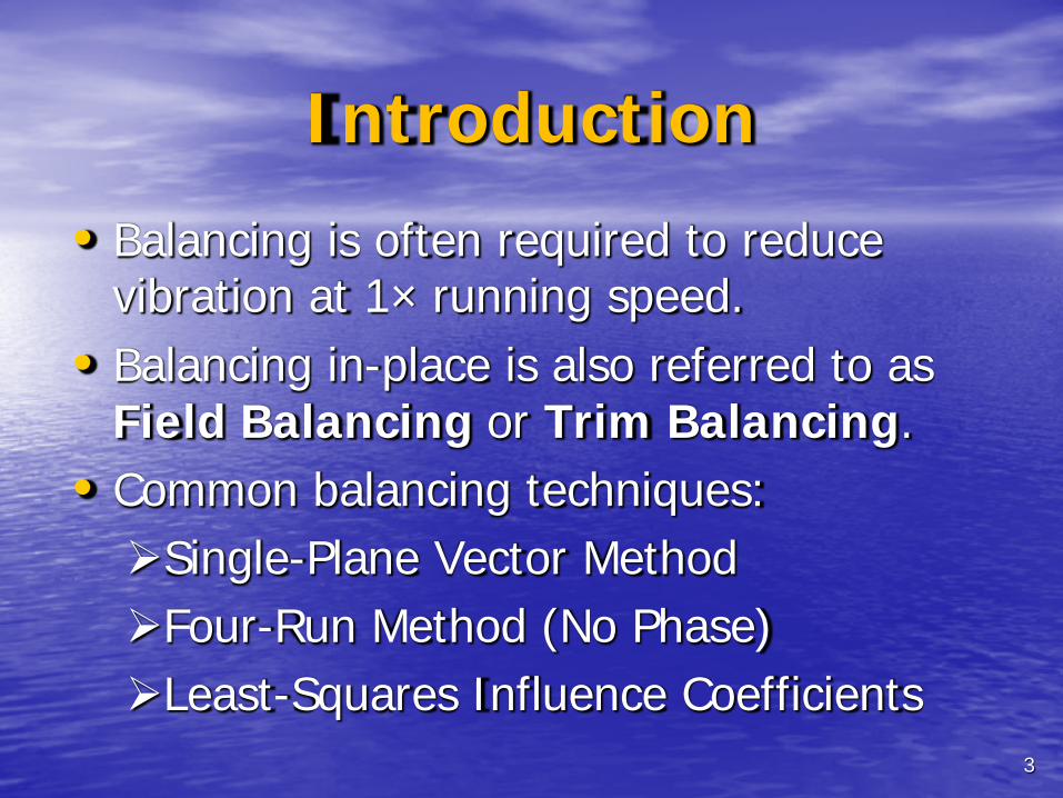
Introduction
• Balancing is often required to reduce vibration at 1× running speed.
• Balancing in-place is also referred to as Field Balancing or Trim Balancing.
• Common balancing techniques: Single-Plane Vector Method Four-Run Method (No Phase) Least-Squares Influence Coefficients
3
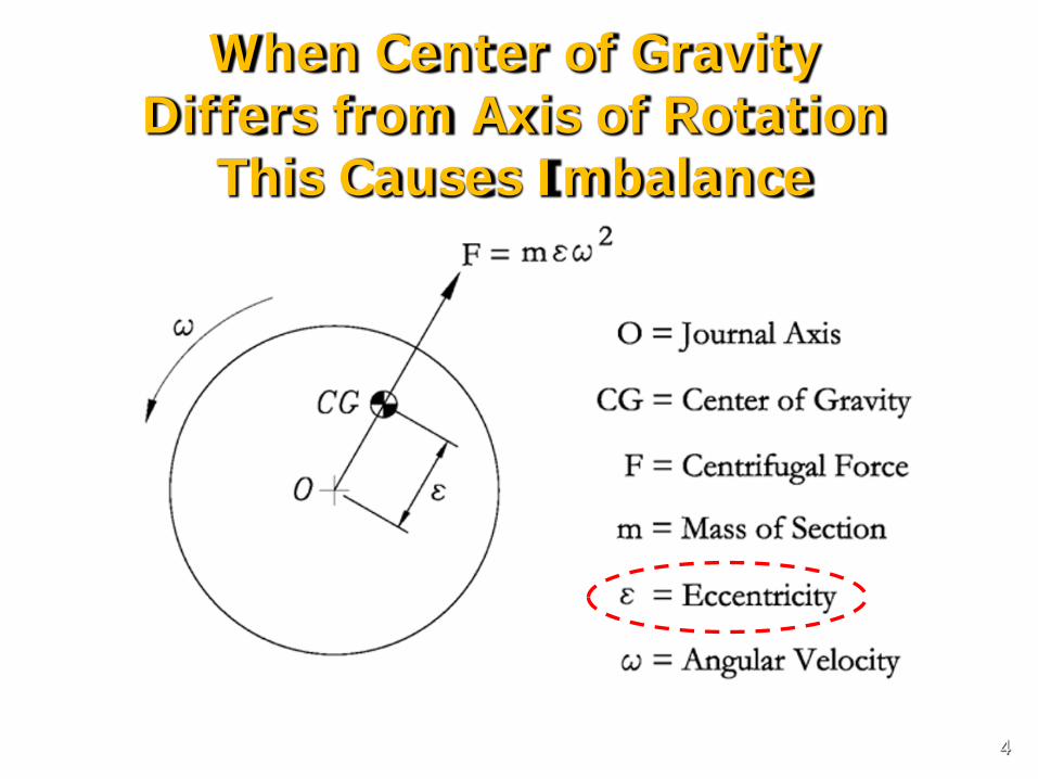
When Center of Gravity Differs from Axis of Rotation
This Causes Imbalance
4
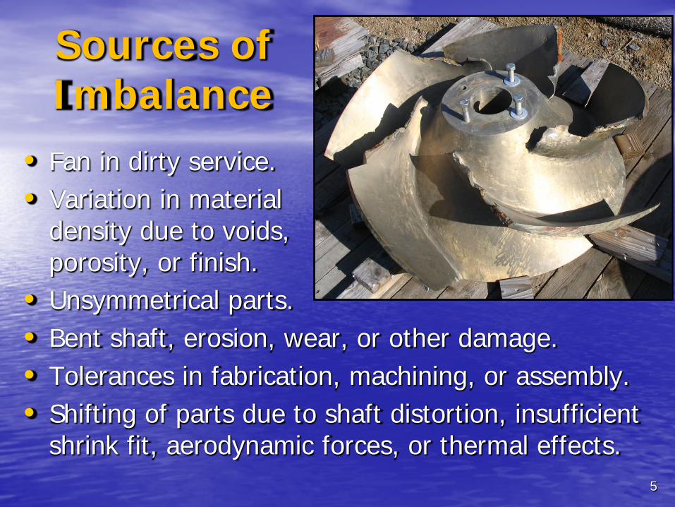
Sources of Imbalance
• Fan in dirty service. • Variation in material
density due to voids, porosity, or finish.
• Unsymmetrical parts. • Bent shaft, erosion, wear, or other damage. • Tolerances in fabrication, machining, or assembly. • Shifting of parts due to shaft distortion, insufficient
shrink fit, aerodynamic forces, or thermal effects. 5

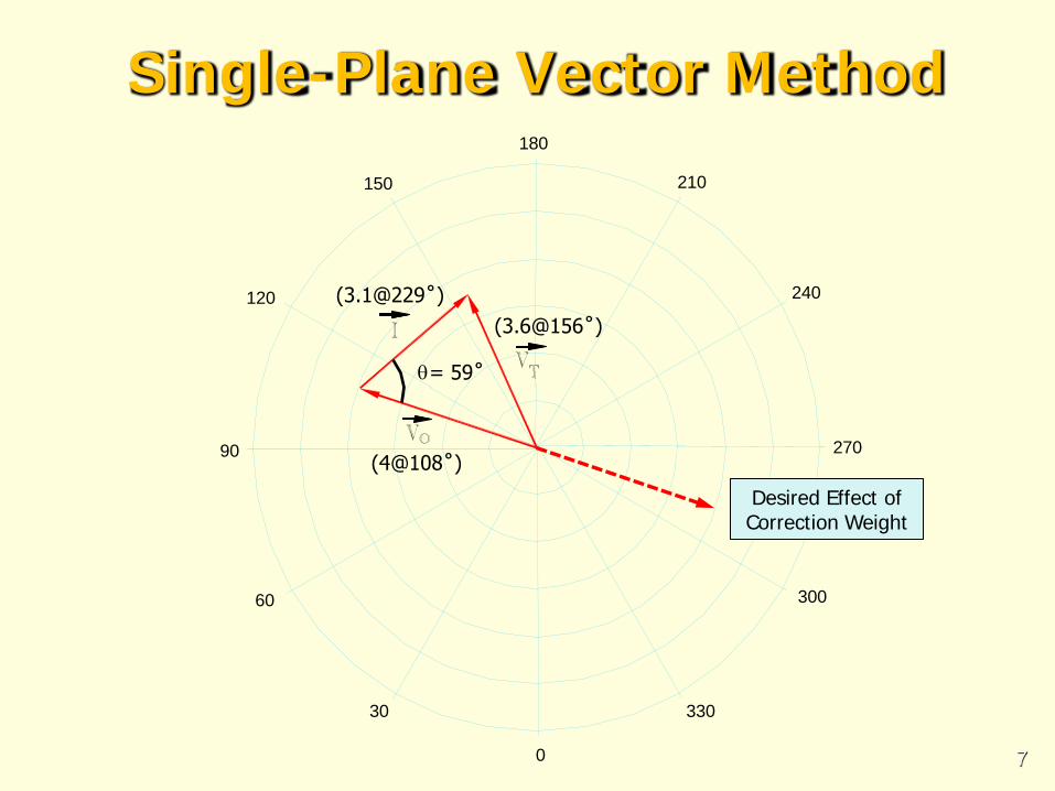
Review of Vector Method
• VO represents the original vibration reading (as found or baseline)
• VT is the vibration due to the trial weight plus original vibration
• Vector I (influence) is determined by subtracting VO (original) from VT (trial)
6
180
210
240
270
300
330
0
30
60
90
120
150
Single-Plane Vector Method
(4@108˚)
(3.6@156˚) (3.1@229˚)
θ
Desired Effect of Correction Weight
= 59˚
7

• Correction Weight = Trial Weight · |VO| / |I|
• Location of CW is determined by angle θ • Should remove TW before installing CW
8
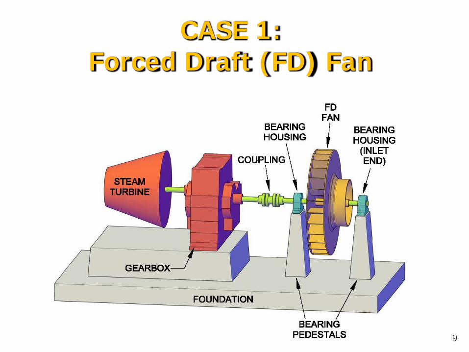
CASE 1: Forced Draft (FD) Fan
9
• Plant Personnel Reported High Vibration of FD Fan After Replacing Roller Bearings
• Second Set of Bearings Were Installed, But Vibration Remained High
• Predominant Vibration at 1× Running Speed of 1745 RPM (29 Hz)
• Reported Difficulty Balancing the Fan
Background Information
10
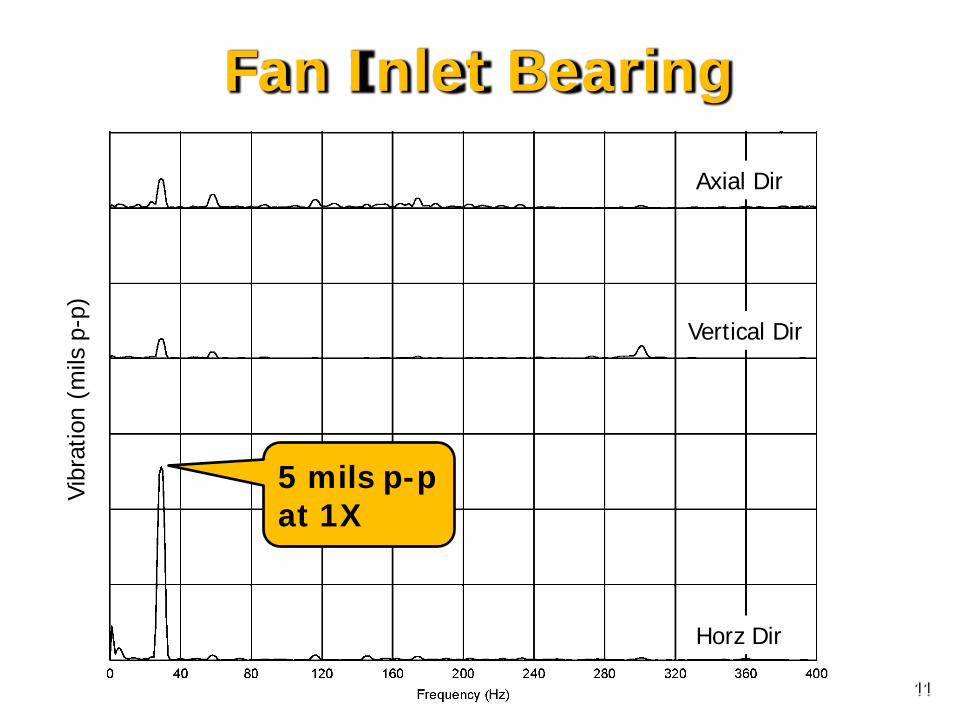
Axial Dir
Vertical Dir
Horz Dir
Fan Inlet Bearing
5 mils p-p at 1X
Vibr
atio
n (m
ils p
-p)
11

Operating Deflection Shape (ODS)
• 3D representation from basic dimensions
• Tri-axial accelerometer used to measure vibration in three directions at 18 points
• Vibration in displacement (mils p-p)
• Phase angles determined from transfer function and stationary accelerometer
• Modal software used to animate motion at 1× running speed (29 Hz)
12
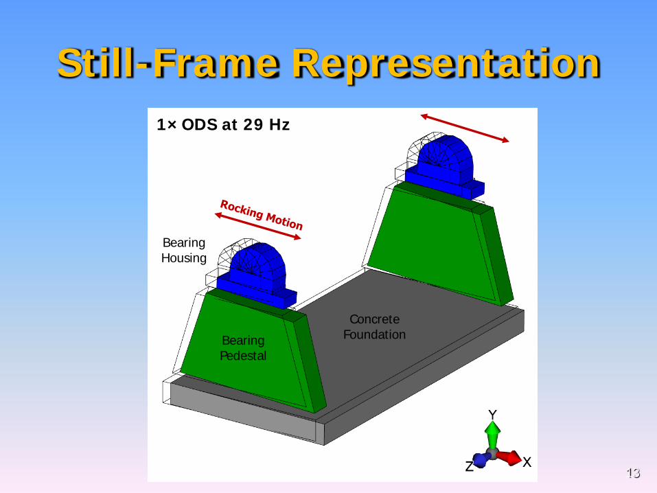
Bearing Housing
Bearing Pedestal
Concrete Foundation
1× ODS at 29 Hz
Still-Frame Representation
13
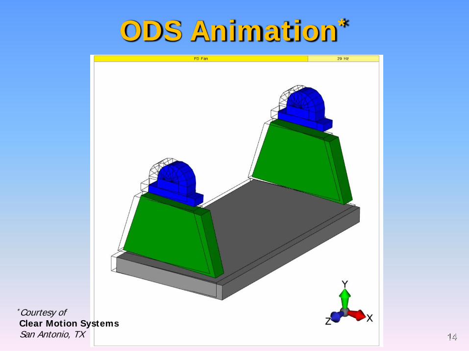
ODS Animation*
14
*Courtesy of Clear Motion Systems San Antonio, TX

FD Fan / 29 Hz
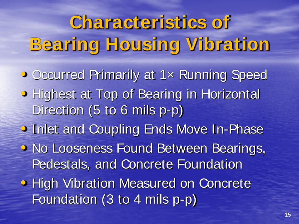
Characteristics of Bearing Housing Vibration
• Occurred Primarily at 1× Running Speed • Highest at Top of Bearing in Horizontal
Direction (5 to 6 mils p-p) • Inlet and Coupling Ends Move In-Phase • No Looseness Found Between Bearings,
Pedestals, and Concrete Foundation • High Vibration Measured on Concrete
Foundation (3 to 4 mils p-p) 15
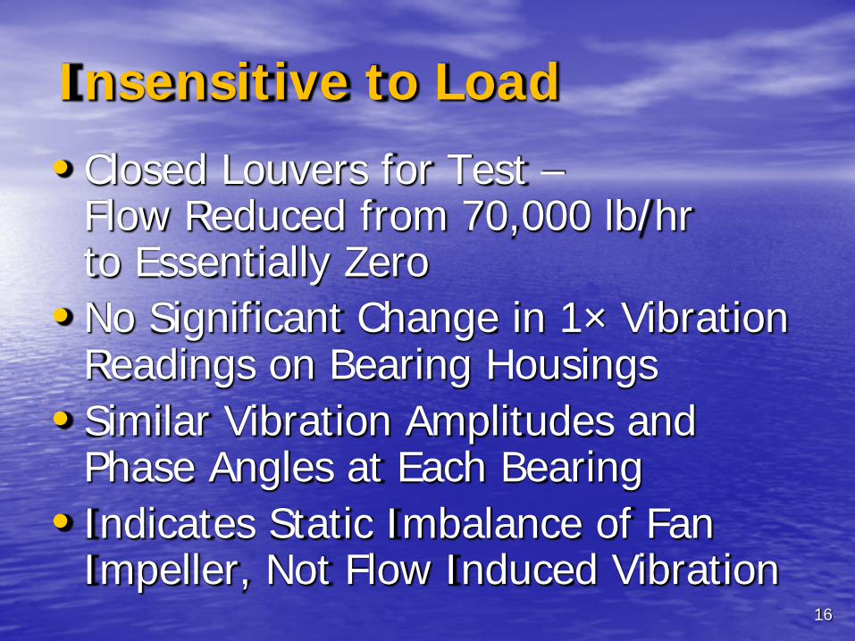
Insensitive to Load
• Closed Louvers for Test – Flow Reduced from 70,000 lb/hr to Essentially Zero
• No Significant Change in 1× Vibration Readings on Bearing Housings
• Similar Vibration Amplitudes and Phase Angles at Each Bearing
• Indicates Static Imbalance of Fan Impeller, Not Flow Induced Vibration 16

Bode Plot Inlet Bearing Housing Horizontal Direction
2 mils p-p
4 mils p-p
6 mils p-p
Phas
e An
gle
1× V
ibra
tion
Theoretical Imbalance
Only
Phase Shift
Amplified Vibration
17
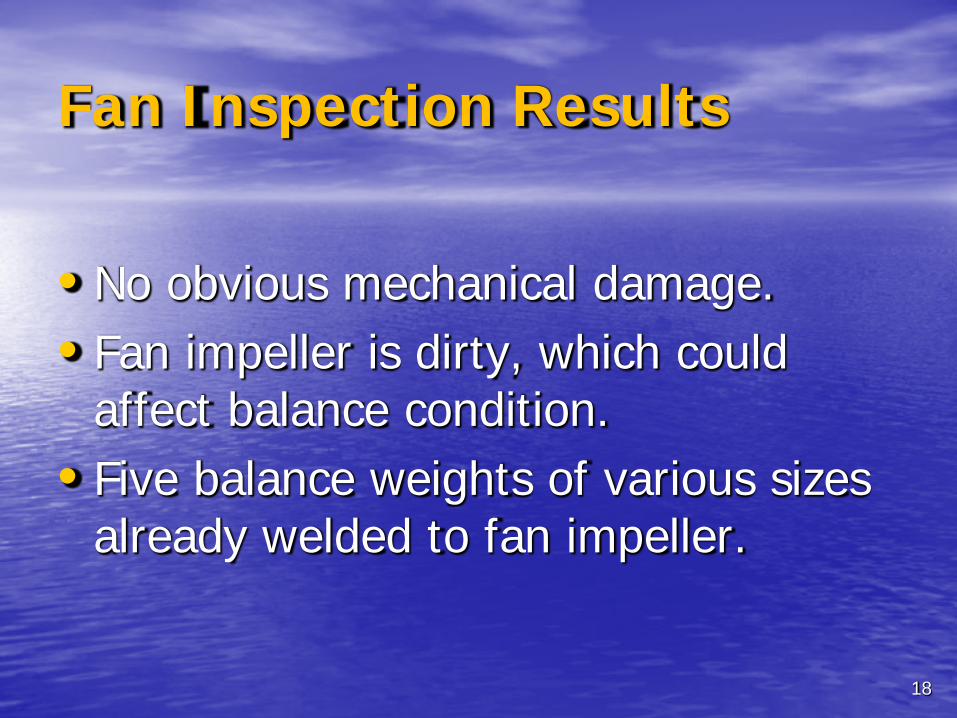
Fan Inspection Results
• No obvious mechanical damage. • Fan impeller is dirty, which could
affect balance condition. • Five balance weights of various sizes
already welded to fan impeller.
18
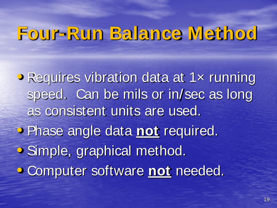
Four-Run Balance Method
• Requires vibration data at 1× running speed. Can be mils or in/sec as long as consistent units are used.
• Phase angle data not required. • Simple, graphical method. • Computer software not needed.
19

Four-Run Balance Method Good method for balancing near resonance since it does not rely on phase angles. Results can easily be derived using polar plot paper and a compass. Assume static imbalance of fan impeller (single plane).
Steps: 1. Number fan blades from 0 to 11, opposite rotation
2. Readings taken with the fan running at 1745 RPM
3. Speed verified with optical tach and strobe light
20
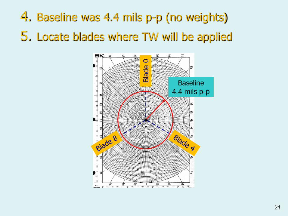
4. Baseline was 4.4 mils p-p (no weights)
5. Locate blades where TW will be applied
Baseline 4.4 mils p-p
Blad
e 0
21
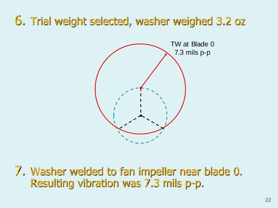
7. Washer welded to fan impeller near blade 0. Resulting vibration was 7.3 mils p-p.
TW at Blade 0 7.3 mils p-p
6. Trial weight selected, washer weighed 3.2 oz
22
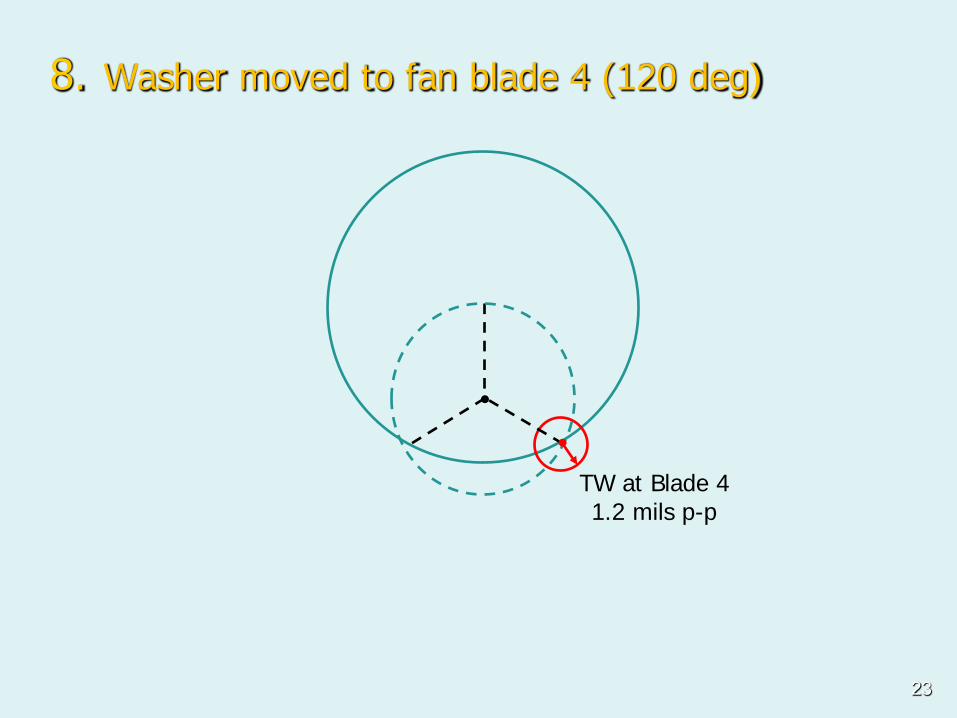
8. Washer moved to fan blade 4 (120 deg)
TW at Blade 4 1.2 mils p-p
23
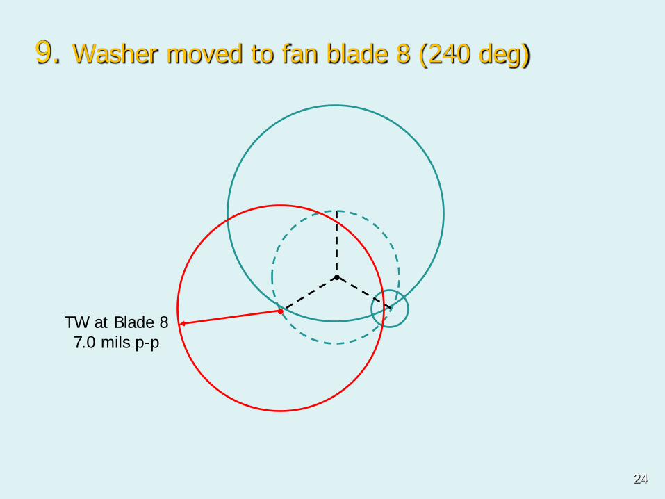
9. Washer moved to fan blade 8 (240 deg)
TW at Blade 8 7.0 mils p-p
24
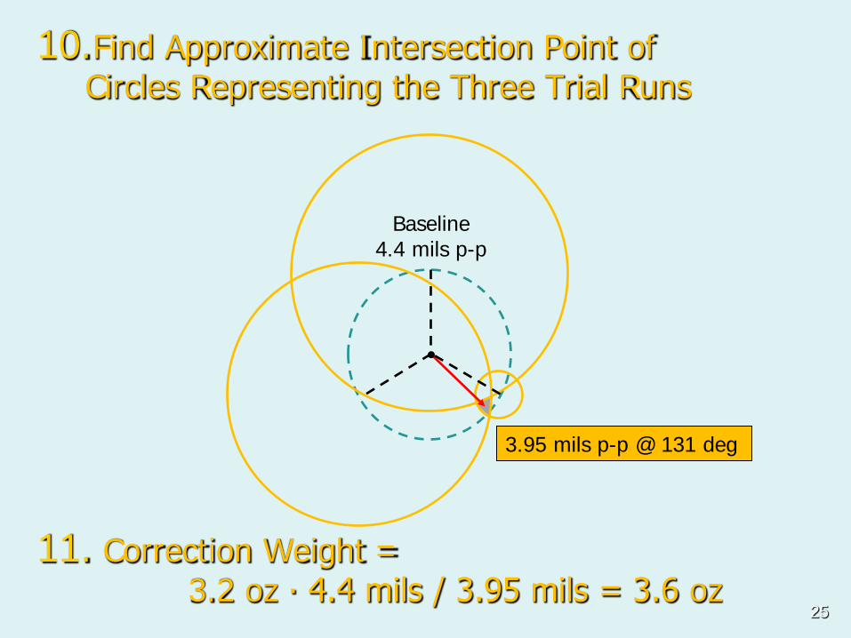
10.Find Approximate Intersection Point of Circles Representing the Three Trial Runs
3.95 mils p-p @ 131 deg
11. Correction Weight = 3.2 oz ∙ 4.4 mils / 3.95 mils = 3.6 oz
Baseline 4.4 mils p-p
25

Balance Summary
• Fan blade 4 was optimum location • Correction weight was 3.6 oz, slightly
more than trial weight of 3.2 oz • Bearing vibration was reduced to
1.2 mil p-p (0.1 ips peak at 29 Hz) • Final balanced condition was
considered acceptable for operation
26
Case 1 – Conclusions • When balancing near a resonant condition,
phase angles may vary. Using simple four-run method was good option for the FD fan.
• Natural frequencies of the fan rotor, impeller, and foundation should have a separation margin of at least 10% from the operating speed range to avoid high sensitivity to small amounts of imbalance, fouling, etc.
• The FD fan moves air at ambient temperature so thermal effects are not prevalent like an induced draft (ID) fan or turbine would be.
27

Case 2: Balancing Gas Turbine
28

Background
• Turbine has history of high vibration since commissioning 20 years ago.
• Previous balance attempts were largely unsuccessful.
• The keyphasor (KP) was unreliable making it difficult to reuse influence coefficients.
• Several other problems found with couplings, bearing pitting, and magnetism.
29

Bearing Housing Vibration (ips)
Vibration Measurements
Bently Panel for Shaft Proximity Probes (mils)
30
Observations
• A temporary optical KP was installed. • Vibration amplitudes and phase angles
were trended over several hours. • It was determined that 3 hours were
required to stabilize the turbine vibration while generating 35 MW of power.
• Previous balance attempts did not allow sufficient time for heat soaking of rotor. 31

Vibration Trend (3-Hr Period)
Constant Load
Star
tup
Shut
dow
n
32
Stable Values
Influence Coefficients
• Determined from trial weights and vibration measurements.
• Goodman (1964) applied least squares. • Assumed linear behavior. • Can be used with multiple balance planes
and operating speeds. • Predicted residuals indicate if rotor can
theoretically be balanced.
33
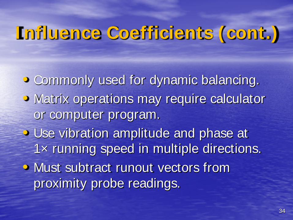
Influence Coefficients (cont.)
• Commonly used for dynamic balancing. • Matrix operations may require calculator
or computer program. • Use vibration amplitude and phase at
1× running speed in multiple directions. • Must subtract runout vectors from
proximity probe readings.
34

Steps: • Obtain baseline vibration (amplitude and phase) after
machine is heat soaked and readings stabilize. • Install trial weight and retake vibration readings. • The angular location of trial weight is typically
referenced to the key phasor, opposite shaft rotation. • Repeat for each balance plane. • The influence coefficients are calculated by
subtracting the baseline from the trial data and dividing by the trial weight.
• Solve for the correction weight(s) needed to minimize residual vibration.
35
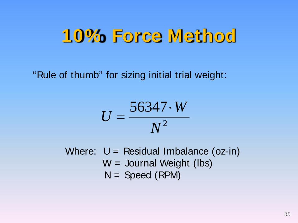
10% Force Method
Where: U = Residual Imbalance (oz-in) W = Journal Weight (lbs) N = Speed (RPM)
256347
NWU ⋅
=
“Rule of thumb” for sizing initial trial weight:
36
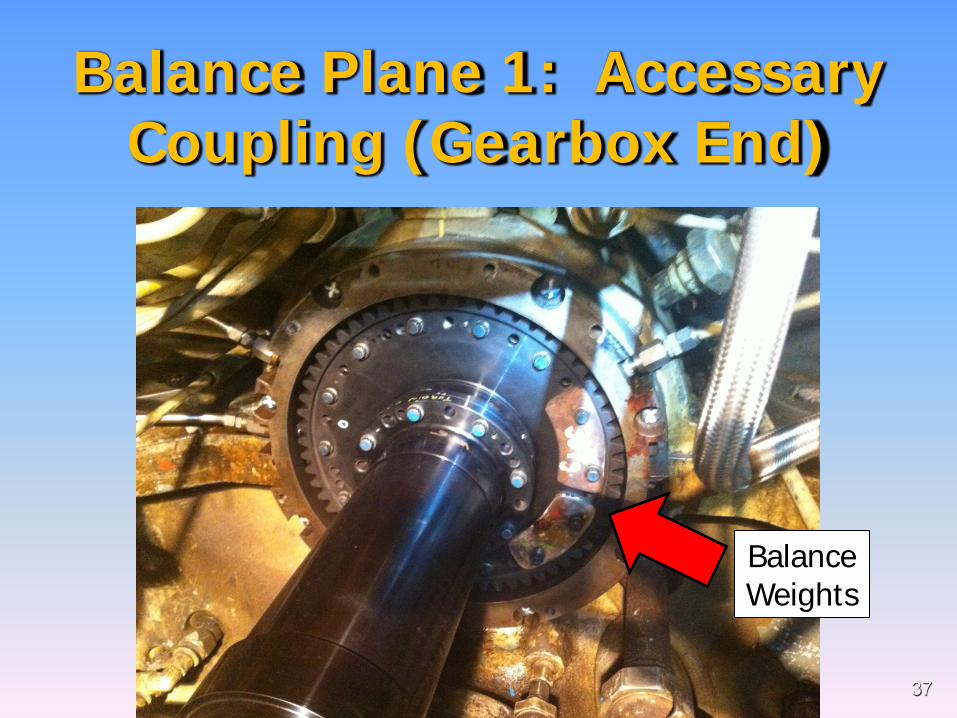
Balance Plane 1: Accessary Coupling (Gearbox End)
Balance Weights
37

Balance Plane 2: Load Coupling (Generator End)
149.6 grams
38

Summary at Base Load
Brg 1 Horz Dir
Brg 1 Vert Dir
Brg 2 Horz Dir
Brg 2 Vert Dir
Plane 1 Mass (g)
Plane 2 Mass (g)
Baseline 5.1 @ 97 3.1 @ -173 3.9 @ -53 1.5 @ -13 - -
TW PL1 4.85 @ 77 5.2 @ -176 7.3 @ -27 1.1 @ 69 307 @ 51 -
TW PL2 5.0 @ 71 3.9 @ 169 5.1 @ -37 0.74 @ 46 - 150 @ 45
Prediction 1.5 @ 66 1.4 @ 352 0.84 @ 342 1.3 @ 13 667 @ 174 505 @ 343
Correction 1.5 @ 107 0.2 @ 6 1.75 @ -41 1.5 @ 7 555 @ 180 440 @ 345
% Change -70% -93% -55% 0%
1X Vibration (mils p-p @ deg)
By balancing on the turbine couplings, the shaft vibration was reduced from 5.1 to 1.75 mils p-p.
39
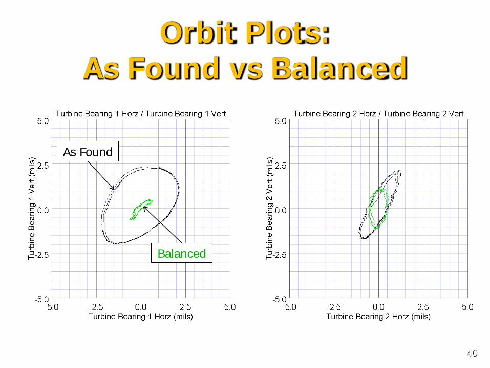
Orbit Plots: As Found vs Balanced
As Found
Balanced
40

Case 2 – Conclusions • Turbine vibration readings are often sensitive to heat
and load. During the testing, approx. 3 hours were required for the vibration readings to stabilize. Even after steady readings, vibration could still vary with load.
• Final correction weights were installed “out-of-phase” on both ends of the turbine. This indicates sensitivity to the conical whirl mode and not the rotor midspan mode, which would have “in-phase” vibration at both bearings.
• Large weights were required to balance the turbine, which indicates available balance planes are at ineffective locations compared with where the actual imbalance occurs in the rotor.
41

References • Feese, T., “Least Squares Balance Program for the
Hewlett-Packard 48GX Calculator,” Vibrations Magazine, March 1998.
• Feese, T., “High Shaft Vibration of Synchronous Generator,” Vibrations Magazine, December 1998.
• Feese, T. D. and Grazier, P. E., “Balance This! Case Histories from Difficult Balancing Jobs,” 33rd Texas A&M Turbomachinery Symposium, September 2004.
• Fox, Randall, “Dynamic Balancing,” 9th Texas A&M Turbomachinery Symposium, 1980.
• Goodman, Thomas P., “A Least-Squares Method for Computing Balance Corrections,” J. Engrg. Indus., Trans. ASME, August 1964.
42

References (cont.) • Jackson, Charles, “Single Plane Balancing,” Texas A&M
Turbomachinery Symposium, February 1991. • MacPherson, H., Taylor, T., Feese, T., “An 11000 RPM
Steam Turbine Case History,” Canadian Machinery Vibration Association, 2003.
• Shreve, Dennis, “Balancing Without Phase,” UPTIME Magazine, January 2011.
• Smith, D. R. and Wachel, J. C., “Controlling Fan Vibration – Case Histories,” EPRI Symposium on Power Plant Fans: The State of the Art, Indianapolis, Indiana, Oct. 1981.
• Wowk, Victor, Machinery Vibration: Balancing, McGraw-Hill, 1995.
43