Embed Size (px)
Citation preview
Solution for PD Pump Suction Piping System Pulsation/Vibration Problem
CASE STUDY:
Eugene L. Broerman, III “Buddy” – Sr. Research Engineer Ray G. Durke – Sr. Research Engineer
Southwest Research Institute
Author’s Biography
• Eugene "Buddy" Broerman is a Senior Research Engineer with Southwest Research Institute (SwRI). He has nearly 13 years of experience with pulsation/vibration related problems. He holds a bachelor’s degree in mechanical engineering from Texas A&M University – Kingsville. Contact him at: [email protected]
• Ray Durke is a Senior Research Engineer with Southwest Research Institute (SwRI). He has 35 years experience in plant dynamics, primarily in diagnosing and correcting machinery vibration and pulsation-related problems. He holds a BSME from Texas A&M University and an MBA from UTSA. Contact him at: [email protected]
2
Agenda
• Introduce System & Problem
• Steps taken to Solve Problem
• Summary & Lessons Learned
3
Pump Description Details
4
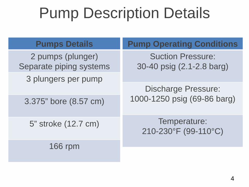
Pumps Details 2 pumps (plunger)
Separate piping systems 3 plungers per pump
3.375” bore (8.57 cm)
5” stroke (12.7 cm)
166 rpm
Pump Operating Conditions Suction Pressure:
30-40 psig (2.1-2.8 barg)
Discharge Pressure: 1000-1250 psig (69-86 barg)
Temperature:
210-230°F (99-110°C)
Problems
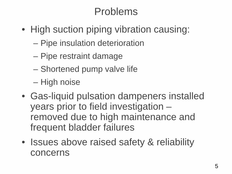
• High suction piping vibration causing: – Pipe insulation deterioration – Pipe restraint damage – Shortened pump valve life – High noise
• Gas-liquid pulsation dampeners installed years prior to field investigation – removed due to high maintenance and frequent bladder failures
• Issues above raised safety & reliability concerns
5
Steps Taken to Solve Problem
• Field investigation for problem characterization and diagnostics – vibration & pulsation data measured
• Pulsation analysis conducted to develop potential solutions
• Maintenance-free, all-liquid acoustic filter bottle recommended
6
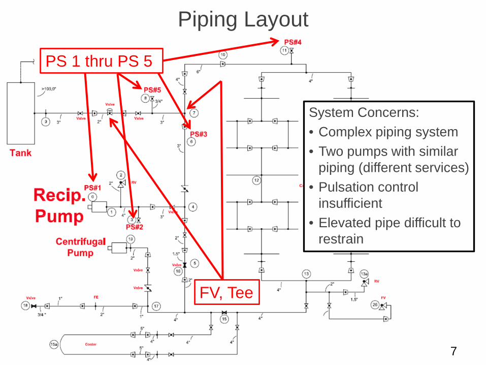
Piping Layout
7
PS 1 thru PS 5
FV, Tee
System Concerns: • Complex piping system • Two pumps with similar
piping (different services) • Pulsation control
insufficient • Elevated pipe difficult to
restrain
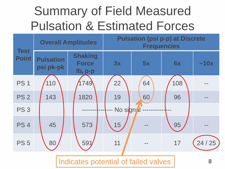
Summary of Field Measured Pulsation & Estimated Forces
8
Test Point
Overall Amplitudes Pulsation (psi p-p) at Discrete Frequencies
Pulsation psi pk-pk
Shaking Force lbf p-p
3x 5x 6x ~10x
PS 1 110 1749 22 64 108 --
PS 2 143 1820 19 60 96 --
PS 3 --------------- No signal --------------
PS 4 45 573 15 -- 95 --
PS 5 80 591 11 -- 17 24 / 25
Indicates potential of failed valves
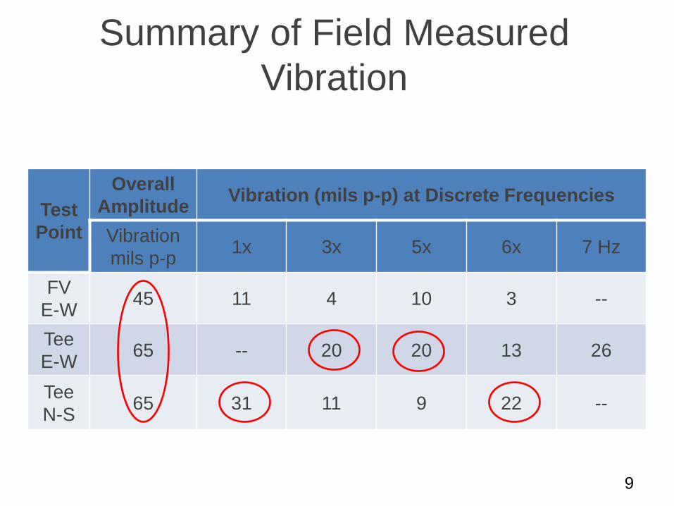
Summary of Field Measured Vibration
9
Test Point
Overall Amplitude Vibration (mils p-p) at Discrete Frequencies
Vibration mils p-p 1x 3x 5x 6x 7 Hz
FV E-W 45 11 4 10 3 --
Tee E-W 65 -- 20 20 13 26
Tee N-S 65 31 11 9 22 --
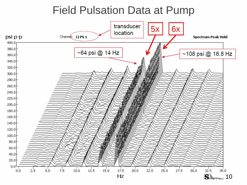
Field Pulsation Data at Pump
10
5x 6x
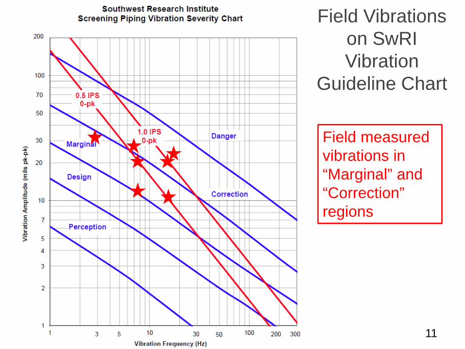
Field Vibrations on SwRI Vibration
Guideline Chart
11
Field measured vibrations in “Marginal” and “Correction” regions
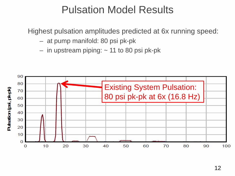
Pulsation Model Results
Highest pulsation amplitudes predicted at 6x running speed: – at pump manifold: 80 psi pk-pk – in upstream piping: ~ 11 to 80 psi pk-pk
12
Existing System Pulsation: 80 psi pk-pk at 6x (16.8 Hz)
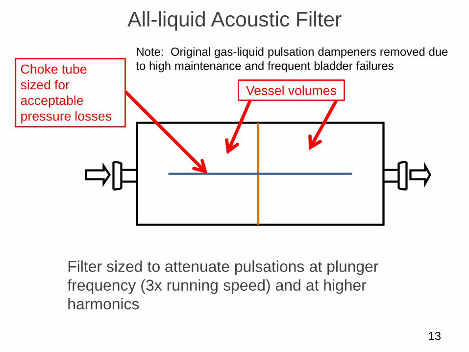
All-liquid Acoustic Filter
13
Choke tube sized for acceptable pressure losses
Vessel volumes
Filter sized to attenuate pulsations at plunger frequency (3x running speed) and at higher harmonics
Note: Original gas-liquid pulsation dampeners removed due to high maintenance and frequent bladder failures
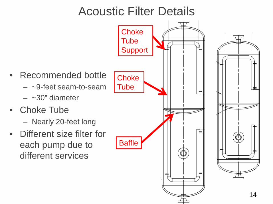
Acoustic Filter Details
14
• Recommended bottle – ~9-feet seam-to-seam – ~30” diameter
• Choke Tube – Nearly 20-feet long
• Different size filter for each pump due to different services
Baffle
Choke Tube
Choke Tube Support
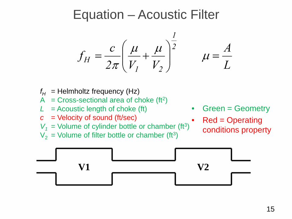
Equation – Acoustic Filter
15
fH = Helmholtz frequency (Hz) A = Cross-sectional area of choke (ft2) L = Acoustic length of choke (ft) c = Velocity of sound (ft/sec) V1 = Volume of cylinder bottle or chamber (ft3) V2 = Volume of filter bottle or chamber (ft3)
V2 V1
• Green = Geometry • Red = Operating
conditions property
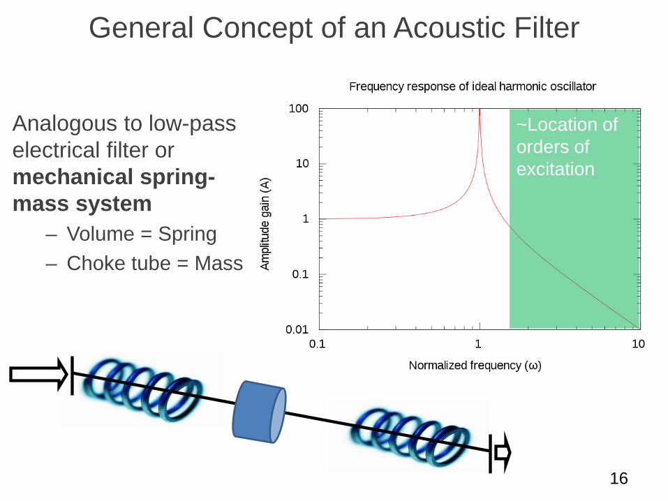
General Concept of an Acoustic Filter
Analogous to low-pass electrical filter or mechanical spring-mass system
– Volume = Spring – Choke tube = Mass
16
~Location of orders of excitation
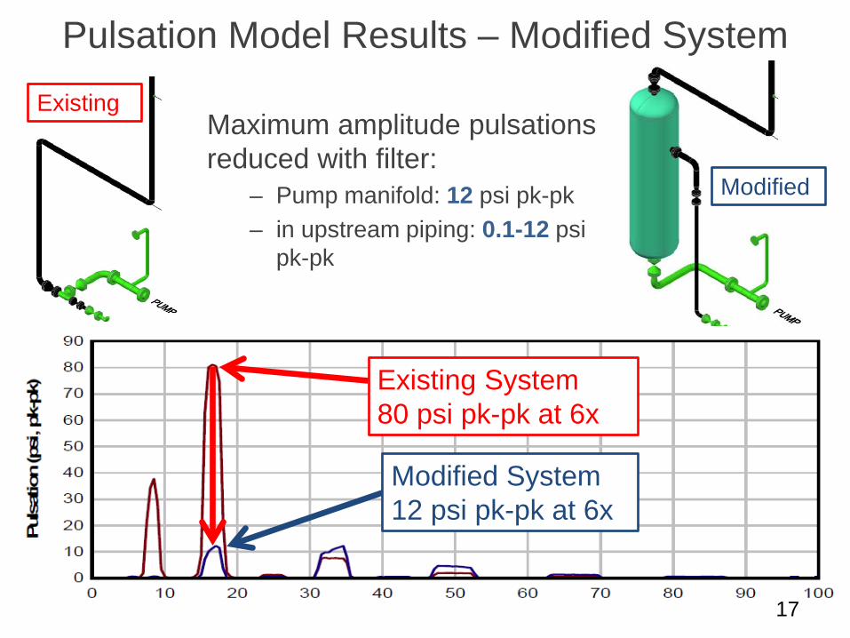
Pulsation Model Results – Modified System
Maximum amplitude pulsations reduced with filter:
– Pump manifold: 12 psi pk-pk – in upstream piping: 0.1-12 psi
pk-pk
17
Existing System 80 psi pk-pk at 6x
Modified System 12 psi pk-pk at 6x
Existing
Modified
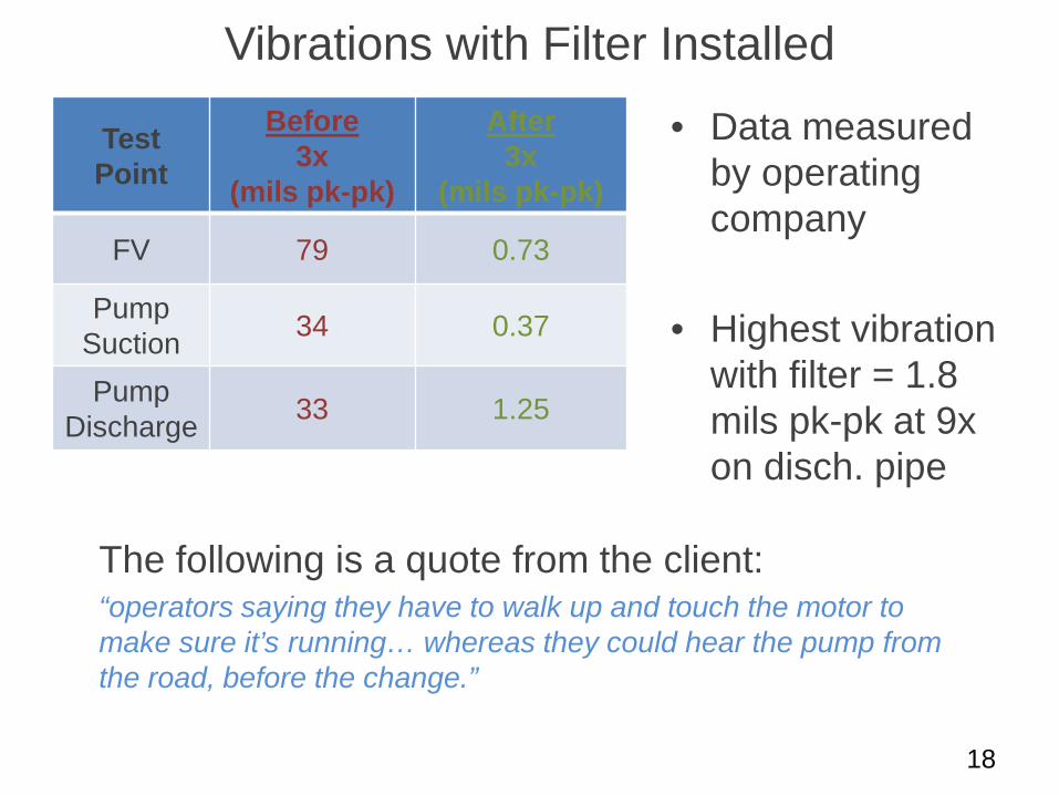
Vibrations with Filter Installed
The following is a quote from the client: “operators saying they have to walk up and touch the motor to make sure it’s running… whereas they could hear the pump from the road, before the change.”
18
Test Point
Before 3x
(mils pk-pk)
After 3x
(mils pk-pk)
FV 79 0.73
Pump Suction 34 0.37
Pump Discharge 33 1.25
• Data measured by operating company
• Highest vibration with filter = 1.8 mils pk-pk at 9x on disch. pipe
Summary and Lessons Learned
• Pump System Problem – High amplitude piping vibrations – Insulation and restraint damage – Gas-liquid dampener bladder failures
• Steps taken to Solve Problem – Field investigation for problem evaluation – vibration &
pulsation measurements – Pulsation analysis
• Summary & Lessons Learned – All-liquid acoustic filter can significantly reduce system
pulsation and vibration amplitudes
19
Questions/Comments?
20
Please ask. If you have a question, someone else in the room probably has a question also.