Embed Size (px)
Citation preview

Case-Study on the Application of PrecastDouble-Curved Concrete Elementsfor the Green Planet Shell Structure
Sietse Witterholt1(&), Roel Schipper2, Steffen Grünewald2,3,Pierre Hoogenboom4, Rob Nijsse2,5, and Hans van Vliet5
1 VDK Engineering bv, Wattstraat 3, 2171 TP Sassenheim, The [email protected]
2 Department of Structural and Building Engineering,Delft University of Technology, Stevinweg 1, 2628 CN Delft, The Netherlands
{H.R.Schipper,S.Grunewald,R.Nijsse}@tudelft.nl3 Magnel Laboratory for Concrete Research, Ghent University,
Technologiepark-Zwijnaarde 904, 9052 Ghent, Belgium4 Section of Structural Mechanics, Delft University of Technology,
Stevinweg 1, 2628 CN Delft, The [email protected]
5 Section of Structural and Building Engineering, ABT bv,Arnhemsestraatweg 358, 6881 NK Velp, The Netherlands
Abstract. Double-curved structures in general, and monolithic concrete shellstructures more specifically, can transfer forces very efficiently. As a result, thethickness-to-span ratio can be very low, which, material-wise, can lead to a veryeconomical design. However, the construction of shell structures is verylabour-intensive and comes with high formwork costs and shells in modernbuilding practice are rarely constructed. Concrete shell structures can be castin-situ making use of temporary formwork and falsework, but they can be(partially) prefabricated as well, like the Palazzetto dello Sport in Rome.Although precasting is an effective technology for the repetitive production ofconcrete elements, for double-curved structures, having a large variety ofshapes, the advantages of precasting seem to diminish quickly as a result of highformwork costs. Another disadvantage of precasting shell elements obviouslyseems to be the complexity of the required connections. For shell structures, theloss of stiffness of the connections might even lead to a crucial reduction of thebuckling stability. A combination of both building methods, the prefabricationof the supportive structure and a finish with a cast in-situ layer, solves thisbefore-mentioned issues and the advantages of both methods are combined:reduction of the complexity of the connections with an in-situ cast concrete layerand integration of the supportive structure in the design for a more cost-efficienterection. This paper describes the study of an innovative, partially precast,alternative solution for the construction of shell structures, and specificallyaddresses the influence of connections between precast elements on the overallshell behaviour. The Green Planet gas station along the A32 highway in TheNetherlands was selected as a design case for such a building method.
© Springer International Publishing AG 2018D.A. Hordijk and M. Luković (eds.), High Tech Concrete: Where Technologyand Engineering Meet, DOI 10.1007/978-3-319-59471-2_284

Keywords: Shell structure � Double-curved � Precast elements � Concretepanels � Flexible mould
1 Introduction
Shell structures break the linearity of daily practicality and often are unique; shellsappeal to the imagination and constitute a landmark herein. Many concrete shellstructures have been constructed and were either produced with prefabricated elementsor in-situ cast. Three famous examples of prefabricated structures with the shape of ashell are the Palazzetto dello Sport [Rome/Italy (Bucur-Horvath and Saplacan 2013)],the Sydney Opera House [Sydney/Australia (Weston 2002)] and the Heydar AliyevCultural Centre [Baku/Azerbaijan (Zaha Hadid Architects 2016)]. Thin shells arecharacterized by two large dimensions and one smaller dimension (the thickness) andthey have a curved middle plane. Therefore, they are able to resist out-of-plane forcesby developing in-plane forces, called membrane forces. This makes shells strong andeffective structures; their behaviour is described in the membrane theory. This theoryholds for the largest part of the shell’s surface, but in some regions the theory will nothold and compatibility moments will compensate the shortcomings of the membranefield. This disturbed zone should be analysed with the more complete bending theory.Together these theories are very useful for initial design and analysis of thin shellstructures (Blaauwendraad and Hoefakker 2014).
State-of-the-art production of double-curved concrete elements for cladding or shellstructures, which are produced in small production numbers, is expensive and a lot ofwaste is produced. With the use of an adjustable re-usable mould system the productionof elements can be more economic and sustainable. The concept of the adjustableformwork has its origin in the ideas of Renzo Piano (Piano 1969). The original ideawas to scale up a small element by measuring it with a machine which communicatesthe data to a flexible formwork system. The innovative flexible mould method foreconomically efficient and sustainable production of prefabricated elements has beenfurther developed at Delft University of Technology (Schipper 2015) and it comprisesthe use of a flexible, CNC-controlled formwork, which is filled with self-compactingconcrete (Schipper and Grünewald 2014). The production comprises casting of anelement in horizontal position and, after a waiting period, the mould is deliberatelydeformed and positioned on pre-arranged mould supports (Fig. 1).
In the period between mixing and de-moulding, the concrete behaviour changesfrom a plastic to a solid state with changing contributions to the yield strength in timeof thixotropic structural build-up and progress of hydration. The element geometry andapplied mix design determine whether the criteria can be fulfilled and if so, the durationof the open window for adequate deformation. Especially, the early phase beforesetting is very important for the production with the flexible mould system. The ele-ment hardens in the deformed mould, which can be re-used for the production ofelements having the same or a different geometry.
Case-Study on the Application of Precast Double-Curved Concrete 2495

2 Design Case ‘Green Planet’
The Green Planet (Fig. 2) is an existing, recently built structure and a supposedly futurelandmark. It is a (gas) service station built along the A32 highway in the North of theNetherlands; the double-curved structure was designed by ABT. As a unique featurethe Green Planet is offering sustainable fuels, which is publicly exhibited by means ofthe shape of the structure. The shape represents a portion of the earth’s surface. Thesurface of the globe on which we live and which is endangered of being compromisedby the use of non-renewable fuels. The Green Planet structure was selected as a designcase and benchmark for the innovative building method discussed in this paper(Witterholt 2016). The method consists of applying double-curved concrete elementsproduced with the flexible mould as an integrated part of the structure; two types of
Fig. 1. Flexible mould system after the deformation of the mould.
Fig. 2. Green Planet gas station in the Netherlands.
2496 S. Witterholt et al.
solutions are possible: (1) prefabricated elements having the same thickness as thestructure or (2) a combination of prefabricated elements with in-situ cast concrete.
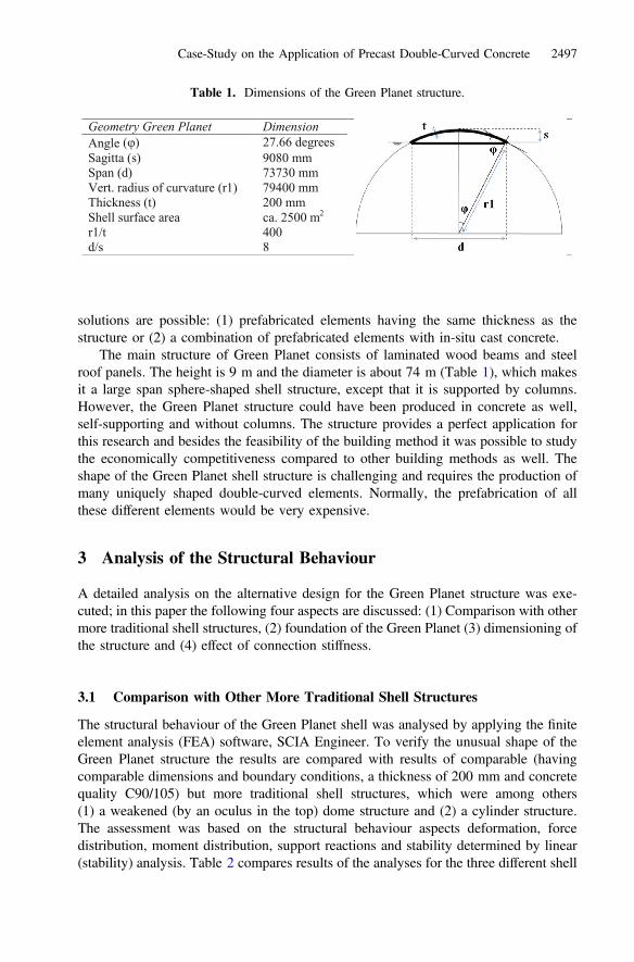
The main structure of Green Planet consists of laminated wood beams and steelroof panels. The height is 9 m and the diameter is about 74 m (Table 1), which makesit a large span sphere-shaped shell structure, except that it is supported by columns.However, the Green Planet structure could have been produced in concrete as well,self-supporting and without columns. The structure provides a perfect application forthis research and besides the feasibility of the building method it was possible to studythe economically competitiveness compared to other building methods as well. Theshape of the Green Planet shell structure is challenging and requires the production ofmany uniquely shaped double-curved elements. Normally, the prefabrication of allthese different elements would be very expensive.
3 Analysis of the Structural Behaviour
A detailed analysis on the alternative design for the Green Planet structure was exe-cuted; in this paper the following four aspects are discussed: (1) Comparison with othermore traditional shell structures, (2) foundation of the Green Planet (3) dimensioning ofthe structure and (4) effect of connection stiffness.
3.1 Comparison with Other More Traditional Shell Structures
The structural behaviour of the Green Planet shell was analysed by applying the finiteelement analysis (FEA) software, SCIA Engineer. To verify the unusual shape of theGreen Planet structure the results are compared with results of comparable (havingcomparable dimensions and boundary conditions, a thickness of 200 mm and concretequality C90/105) but more traditional shell structures, which were among others(1) a weakened (by an oculus in the top) dome structure and (2) a cylinder structure.The assessment was based on the structural behaviour aspects deformation, forcedistribution, moment distribution, support reactions and stability determined by linear(stability) analysis. Table 2 compares results of the analyses for the three different shell
Table 1. Dimensions of the Green Planet structure.
Geometry Green Planet DimensionAngle 27.66 degreesSagitta (s) 9080 mmSpan (d) 73730 mmVert. radius of curvature (r1) 79400 mmThickness (t) 200 mmShell surface area ca. 2500 m2
r1/t 400d/s 8
Case-Study on the Application of Precast Double-Curved Concrete 2497

structures. The aims of this comparison were twofold: (1) to determine which (simple)shell structure is most comparable with the behaviour of Green Planet and (2) to verifythe Green Planet model. The analysis with realistic loads in conformation with therelevant design codes indicated that multiple types of wind loads can be normative forthe internal forces of the structure. The Green Planet structure is mainly subjected tocompressive forces and only in certain areas, along the edge of the shell or near thesupports, tension forces arise. The self-weight is the lowest for the Green Planetstructure, whereas the self-weight is the highest for the weakened dome. The criticalbuckling load is the lowest for the cylinder (0.42) which is much lower compared to theweakened dome (26.21) which has the highest buckling resistance. The highest andlowest maximum membrane stresses were obtained for the cylinder structure; themaximal vertical displacement is also much larger. Therefore, with regard to maximumand minimum membrane stresses and maximum vertical displacement the Green Planetis more comparable with the weakened dome.
3.2 Foundation of the Green Planet
The analysis of the three structures confirmed that large thrust forces will act on thefoundation. Furthermore and in reality, the hinge supports are not infinitely strong ineach direction, as was assumed for the discussed types of structure. A more detailedstudy of the supports was carried out in order to simulate the behaviour of the shellstructure in cooperation with the foundation; use was made again of the mentionedfinite element program software. Originally, the relatively light wood-steel structure issupported by columns and therefore the concrete foundation was subjected tosignificantly smaller support reactions. The Green Planet model was analysed with the
Table 2. Comparison of FEM calculations for three different structures.
Structure 1) Green Planet 2) Weakened dome 3) CylinderFEM Model
Self-weight [kN] 12230 24412 15904
Maximum tensile stress [N/mm2]
4.55 0.12 60.24
Minimum compressivestress [N/mm2]
-8.87 -3.90 -80.64
Vertical support reaction [kN/m]
681.1 109.6 473.7
Max. horiz. support reaction [kN/m]
1281.0 206.2 891.0
Maximum vertical displacement [mm]
20.50 5.39 1874.70
Critical buckling load [kN/m2]
8.10 26.21 0.42
2498 S. Witterholt et al.
assumption that the supports were connected by long steel tension cables. The calcu-lation showed that already due to small horizontal displacements caused by the elon-gation of the cables the resistance against buckling would never suffice. For this reason,it was recommended to make use of post-tension cables or another special foundationthat prevents these deformations.
3.3 Dimensioning of the Structure
The finite element model of the Green Planet was studied with regard to mesh fineness(0,1 to 1 m); a 0.2 m mesh was selected because changes in resulting stresses anddeformations were relatively small compared with smaller sized meshes. The stiffnessof this shell structure strongly depends on the modulus of elasticity of concrete, but sodo the building costs. The model was tested with different combinations of thickness ofthe structure (150 to 250 mm), material strength and modulus of elasticity (concretestrength class: C35/45-C90/105). In an iterative way, the structure was optimized byreducing the thickness down to 150 mm and by locally increasing the thickness to300 mm in order to obtain the same buckling load factor of 6. In the final design, theGreen Planet shell had a constant thickness of 250 mm, a material strength of C45/55and the supports are hinged to limit the effects settlements have on the structure. Inorder to investigate the effect of the connections between the precast elements on thebehaviour of the structure, the model was segmented. A realistic segmentation plan wasimplemented taking into account the boundary conditions with regard to productionand maximum dimensions of elements.
3.4 Effect of Connection Stiffness
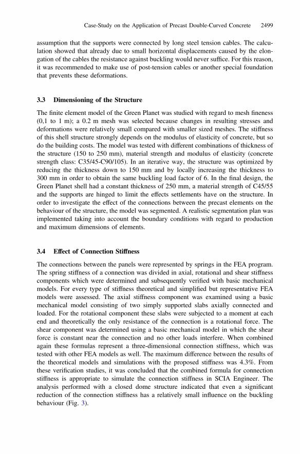
The connections between the panels were represented by springs in the FEA program.The spring stiffness of a connection was divided in axial, rotational and shear stiffnesscomponents which were determined and subsequently verified with basic mechanicalmodels. For every type of stiffness theoretical and simplified but representative FEAmodels were assessed. The axial stiffness component was examined using a basicmechanical model consisting of two simply supported slabs axially connected andloaded. For the rotational component these slabs were subjected to a moment at eachend and theoretically the only resistance of the connection is a rotational force. Theshear component was determined using a basic mechanical model in which the shearforce is constant near the connection and no other loads interfere. When combinedagain these formulas represent a three-dimensional connection stiffness, which wastested with other FEA models as well. The maximum difference between the results ofthe theoretical models and simulations with the proposed stiffness was 4.3%. Fromthese verification studies, it was concluded that the combined formula for connectionstiffness is appropriate to simulate the connection stiffness in SCIA Engineer. Theanalysis performed with a closed dome structure indicated that even a significantreduction of the connection stiffness has a relatively small influence on the bucklingbehaviour (Fig. 3).
Case-Study on the Application of Precast Double-Curved Concrete 2499
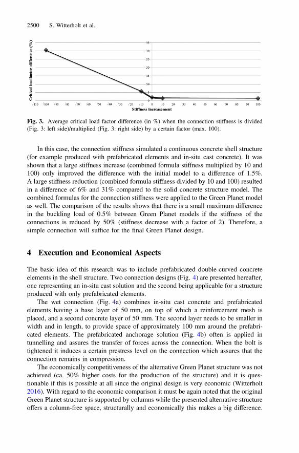
In this case, the connection stiffness simulated a continuous concrete shell structure(for example produced with prefabricated elements and in-situ cast concrete). It wasshown that a large stiffness increase (combined formula stiffness multiplied by 10 and100) only improved the difference with the initial model to a difference of 1.5%.A large stiffness reduction (combined formula stiffness divided by 10 and 100) resultedin a difference of 6% and 31% compared to the solid concrete structure model. Thecombined formulas for the connection stiffness were applied to the Green Planet modelas well. The comparison of the results shows that there is a small maximum differencein the buckling load of 0.5% between Green Planet models if the stiffness of theconnections is reduced by 50% (stiffness decrease with a factor of 2). Therefore, asimple connection will suffice for the final Green Planet design.
4 Execution and Economical Aspects
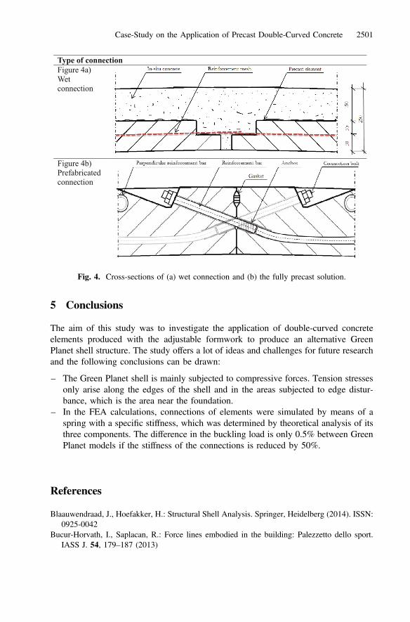
The basic idea of this research was to include prefabricated double-curved concreteelements in the shell structure. Two connection designs (Fig. 4) are presented hereafter,one representing an in-situ cast solution and the second being applicable for a structureproduced with only prefabricated elements.
The wet connection (Fig. 4a) combines in-situ cast concrete and prefabricatedelements having a base layer of 50 mm, on top of which a reinforcement mesh isplaced, and a second concrete layer of 50 mm. The second layer needs to be smaller inwidth and in length, to provide space of approximately 100 mm around the prefabri-cated elements. The prefabricated anchorage solution (Fig. 4b) often is applied intunnelling and assures the transfer of forces across the connection. When the bolt istightened it induces a certain prestress level on the connection which assures that theconnection remains in compression.
The economically competitiveness of the alternative Green Planet structure was notachieved (ca. 50% higher costs for the production of the structure) and it is ques-tionable if this is possible at all since the original design is very economic (Witterholt2016). With regard to the economic comparison it must be again noted that the originalGreen Planet structure is supported by columns while the presented alternative structureoffers a column-free space, structurally and economically this makes a big difference.
Fig. 3. Average critical load factor difference (in %) when the connection stiffness is divided(Fig. 3: left side)/multiplied (Fig. 3: right side) by a certain factor (max. 100).
2500 S. Witterholt et al.
5 Conclusions
The aim of this study was to investigate the application of double-curved concreteelements produced with the adjustable formwork to produce an alternative GreenPlanet shell structure. The study offers a lot of ideas and challenges for future researchand the following conclusions can be drawn:
– The Green Planet shell is mainly subjected to compressive forces. Tension stressesonly arise along the edges of the shell and in the areas subjected to edge distur-bance, which is the area near the foundation.
– In the FEA calculations, connections of elements were simulated by means of aspring with a specific stiffness, which was determined by theoretical analysis of itsthree components. The difference in the buckling load is only 0.5% between GreenPlanet models if the stiffness of the connections is reduced by 50%.
References
Blaauwendraad, J., Hoefakker, H.: Structural Shell Analysis. Springer, Heidelberg (2014). ISSN:0925-0042
Bucur-Horvath, I., Saplacan, R.: Force lines embodied in the building: Palezzetto dello sport.IASS J. 54, 179–187 (2013)
Type of connectionFigure 4a)Wet connection
Figure 4b)Prefabricated connection
Fig. 4. Cross-sections of (a) wet connection and (b) the fully precast solution.
Case-Study on the Application of Precast Double-Curved Concrete 2501
Piano, R.: Progettazione sperimentale per strutture a guscio – experimental project of shellstructures. Casabella 335, 38–49 (1969)
Schipper, H.R.: Double-curved precast concrete elements: Research into technical viability of theflexible mould method.” Ph.D.-thesis, Delft University of Technology (2015). ISBN:978-94-6299-154-5
Schipper, H.R., Grünewald, S.: Efficient material use through smart flexible formwork method.In: Wallevik, O.H., Bager, D.H., Hjartarson, B., Wallevik, J.E. (eds.), Proceedings of theinternational symposium on environmentally friendly concrete-ECO-Crete, Iceland, pp. 61–67 (2014)
Weston, R.: Utzon: Inspiration, Vision, Architecture. Blondal, Hellerup (2002)Witterholt, S.: The application of double-curved precast elements for the project Green Planet.
Master thesis, Delft University of Technology (2016). http://homepage.tudelft.nl/p3r3s/MSc_projects/reportWitterholt.pdf
Zaha Hadid Architects (2016). http://www.zaha-hadid.com/architecture/heydar-aliyev-centre/
2502 S. Witterholt et al.