Embed Size (px)
Citation preview
www.stuartwells.co.uk
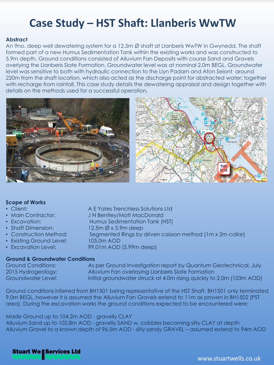
Case Study – HST Shaft: Llanberis WwTW AbstractAn 9no. deep well dewatering system for a 12.5m Ø shaft at Llanberis WwTW in Gwynedd. The shaft formed part of a new Humus Sedimentation Tank within the existing works and was constructed to 5.9m depth. Ground conditions consisted of Alluvium Fan Deposits with course Sand and Gravels overlying the Llanberis Slate Formation. Groundwater level was at nominal 2.0m BEGL. Groundwater level was sensitive to both with hydraulic connection to the Llyn Padarn and Afon Seiont around 220m from the shaft location, which also acted as the discharge point for abstracted water; together with recharge from rainfall. This case study details the dewatering appraisal and design together with details on the methods used for a successful operation.
Scope of Works • Client: A E Yates Trenchless Solutions Ltd• Main Contractor: J N Bentley/Mott MacDonald• Excavation: Humus Sedimentation Tank (HST)• Shaft Dimension: 12.5m Ø x 5.9m deep• Construction Method: Segmented Rings by driven caisson method (1m x 2m collar)• Existing Ground Level: 105.0m AOD• Excavation Level: 99.01m AOD (5.99m deep)
Ground & Groundwater ConditionsGround Conditions: As per Ground Investigation report by Quantum Geotechnical, July 2015 Hydrogeology: Alluvium Fan overlaying Llanberis Slate FormationGroundwater Level: Initial groundwater strruck at 4.0m rising quickly to 2.0m (103m AOD)
Ground conditions inferred from BH1501 being representative of the HST Shaft. BH1501 only terminated 9.0m BEGL, however it is assumed the Alluvium Fan Gravels extend to 11m as proven in BH1502 (PST area). During the excavation works the ground conditions expected to be encountered were:
Made Ground up to 104.2m AOD - gravelly CLAYAlluvium Sand up to 102.8m AOD - gravelly SAND w. cobbles becoming silty CLAY at depthAlluvium Gravel to a known depth of 96.5m AOD - silty sandy GRAVEL – assumed extend to 94m AOD
www.stuartwells.co.uk
Case Study – HST Shaft: Llanberis WwTW
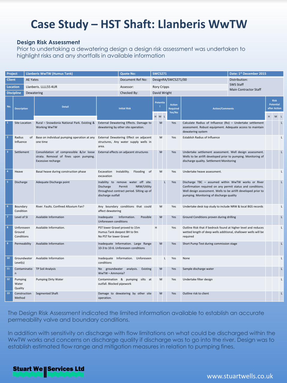
Design Risk AssessmentPrior to undertaking a dewatering design a design risk assessment was undertaken to highlight risks and any shortfalls in available information
Project Llanberis WwTW (Humus Tank) Quote No: SWC5271 Date: 1st December 2015
Client AE Yates Document Ref No: DesignRA/SWC5271/00 Distribution:
SWS Staff
Main Contractor StaffLocation Llanberis. LLLL55 4UR Assessor: Rory Cripps
Discipline Dewatering Checked By: David Wright
No.Description
DetailInitial Risk
Potentia
l Action
Required
Yes/No
Action/Comments
Risk
Potential
after Action
H M L H M L
1 Site Location Rural – Snowdonia National Park. Existing &
Working WwTW
External Dewatering Effects. Damage to
dewatering by other site operation.
M Yes Calculate Radius of Influence (Ro) – Undertake settlement
assessment. Robust equipment. Adequate access to maintain
dewatering system
L
2 Radius of
Influence
Base on individual pumping operation at any
one time
External Dewatering Effect on adjacent
structures, Any water supply wells in
area.
M Yes Establish Radius of Influence L
3 Settlement Consolidation of compressible &/or loose
strata. Removal of fines upon pumping.
Excessive recharge
External effects on adjacent structures M Yes Undertake settlement assessment. Well design assessment.
Wells to be airlift developed prior to pumping. Monitoring of
discharge quality. Settlement Monitoring
L
4 Heave Basal heave during construction phase Excavation Instability. Flooding of
excavation
M Yes Undertake heave assessment. L
5 Discharge Adequate Discharge point Inability to remove water off site.
Discharge Permit NRW/Utility
throughout contract period. Silting up of
discharge outfall
L Yes Discharge TBC – assumed within WwTW works or River
Confirmation required on any permit status and conditions.
Well design assessment. Wells to be airlift developed prior to
pumping. Monitoring of discharge quality
L
6 Boundary
Condition
River. Faults. Confined Alluvium Fan? Any boundary conditions that could
affect dewatering
M Yes Undertake desk top study to include NRW & local BGS records L
7 Level of SI Available Information Inadequate Information. Possible
Unforeseen conditions
M Yes Ground Conditions proven during drilling L
8 Unforeseen
Ground
Conditions
Available Information. PST lower Gravel proved to 15m
Humus Tank deepest BH to 9m
No PST for lower Gravel
H Yes Outline Risk that if bedrock found at higher level and reduces
wetted length of deep wells additional, shallower wells will be
required
L
9 Permeability Available Information Inadequate Information. Large Range
10-3 to 10-6. Unforeseen conditions
M Yes Short Pump Test during commission stage L
10 Groundwater
Level(s)
Available Information Inadequate Information. Unforeseen
conditions
L Yes None L
11 Contaminatio
n
TP Soil Analysis No groundwater analysis. Existing
WwTW – Ammonia?
M Yes Sample discharge water L
12 Pumping
Water
Quality
Pumping Dirty Water Contamination & pumping silts at
outfall. Blocked pipework
M Yes Undertake filter design L
13 Construction
Method
Segmented Shaft Damage to dewatering by other site
operation.
M Yes Outline risk to client L
The Design Risk Assessment indicated the limited information available to establish an accurate permeability valve and boundary conditions.
In addition with sensitivity on discharge with flow limitations on what could be discharged within the WwTW works and concerns on discharge quality if discharge was to go into the river. Design was to establish estimated flow range and mitigation measures in relation to pumping fines.
Dewatering Case Study – HST Shaft: Llanberis WwTW
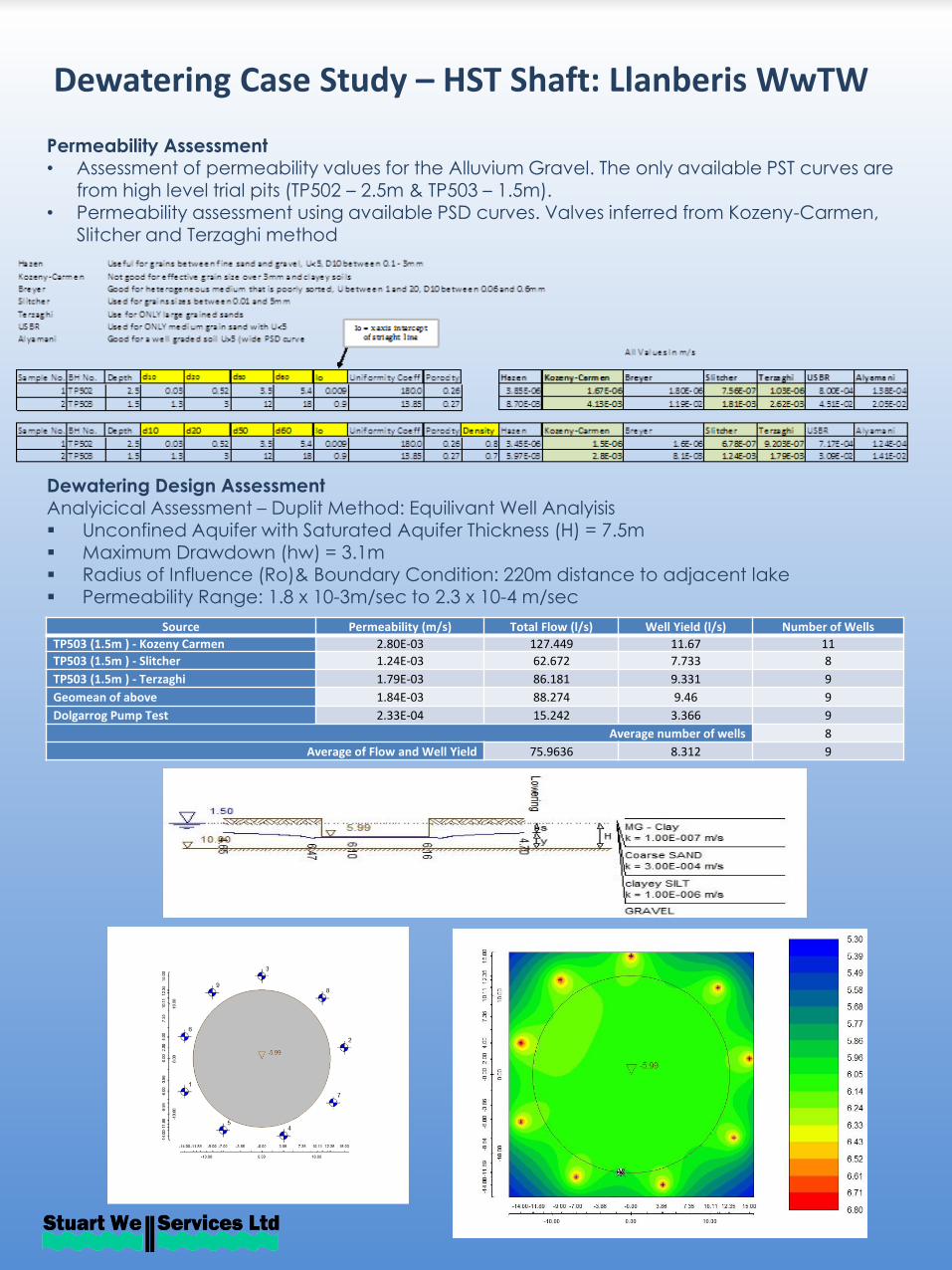
Permeability Assessment• Assessment of permeability values for the Alluvium Gravel. The only available PST curves are
from high level trial pits (TP502 – 2.5m & TP503 – 1.5m).• Permeability assessment using available PSD curves. Valves inferred from Kozeny-Carmen,
Slitcher and Terzaghi method
Dewatering Design AssessmentAnalyicical Assessment – Duplit Method: Equilivant Well Analyisis Unconfined Aquifer with Saturated Aquifer Thickness (H) = 7.5m Maximum Drawdown (hw) = 3.1m Radius of Influence (Ro)& Boundary Condition: 220m distance to adjacent lake Permeability Range: 1.8 x 10⁻³m/sec to 2.3 x 10⁻⁴ m/sec
Source Permeability (m/s) Total Flow (l/s) Well Yield (l/s) Number of Wells
TP503 (1.5m ) - Kozeny Carmen 2.80E-03 127.449 11.67 11
TP503 (1.5m ) - Slitcher 1.24E-03 62.672 7.733 8
TP503 (1.5m ) - Terzaghi 1.79E-03 86.181 9.331 9
Geomean of above 1.84E-03 88.274 9.46 9
Dolgarrog Pump Test 2.33E-04 15.242 3.366 9
Average number of wells 8
Average of Flow and Well Yield 75.9636 8.312 9
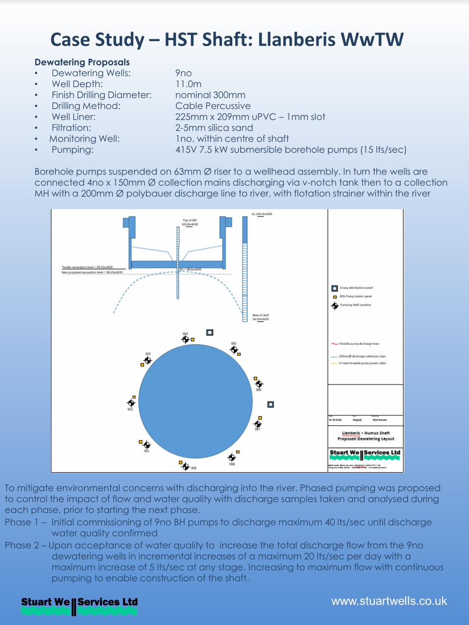
Case Study – HST Shaft: Llanberis WwTW Dewatering Proposals• Dewatering Wells: 9no • Well Depth: 11.0m • Finish Drilling Diameter: nominal 300mm• Drilling Method: Cable Percussive • Well Liner: 225mm x 209mm uPVC – 1mm slot • Filtration: 2-5mm silica sand• Monitoring Well: 1no. within centre of shaft • Pumping: 415V 7.5 kW submersible borehole pumps (15 lts/sec)
Borehole pumps suspended on 63mm Ø riser to a wellhead assembly. In turn the wells are connected 4no x 150mm Ø collection mains discharging via v-notch tank then to a collection MH with a 200mm Ø polybauer discharge line to river, with flotation strainer within the river
To mitigate environmental concerns with discharging into the river. Phased pumping was proposed to control the impact of flow and water quality with discharge samples taken and analysed during each phase, prior to starting the next phase.
Phase 1 – Initial commissioning of 9no BH pumps to discharge maximum 40 lts/sec until discharge water quality confirmed
Phase 2 – Upon acceptance of water quality to increase the total discharge flow from the 9no dewatering wells in incremental increases of a maximum 20 lts/sec per day with a maximum increase of 5 lts/sec at any stage. Increasing to maximum flow with continuous pumping to enable construction of the shaft.
Case Study – HST Shaft: Llanberis WwTW
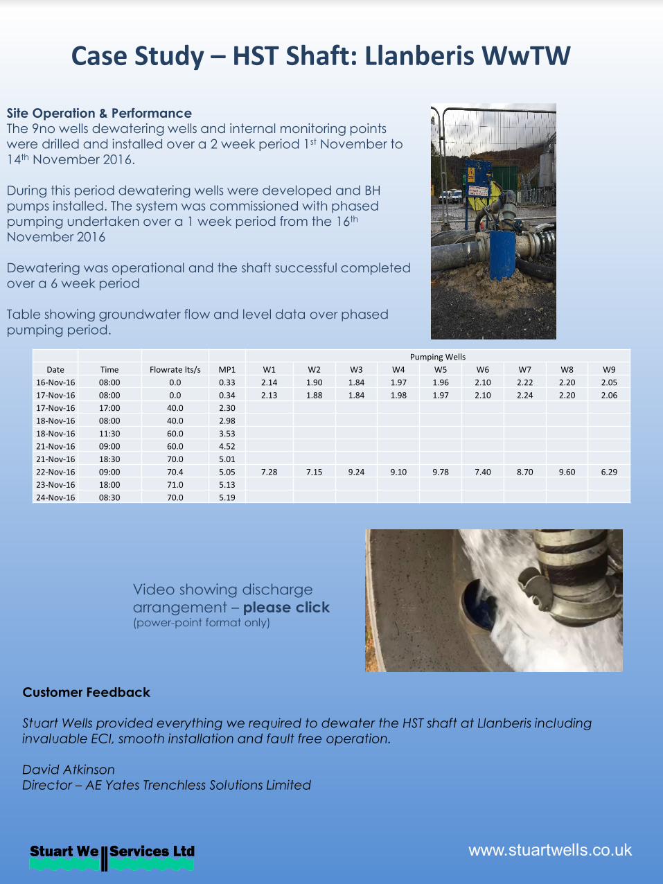
Site Operation & PerformanceThe 9no wells dewatering wells and internal monitoring points were drilled and installed over a 2 week period 1st November to 14th November 2016.
During this period dewatering wells were developed and BH pumps installed. The system was commissioned with phased pumping undertaken over a 1 week period from the 16th
November 2016
Dewatering was operational and the shaft successful completed over a 6 week period
Table showing groundwater flow and level data over phased pumping period.
Video showing discharge
arrangement – please click(power-point format only)
Pumping Wells
Date Time Flowrate lts/s MP1 W1 W2 W3 W4 W5 W6 W7 W8 W9
16-Nov-16 08:00 0.0 0.33 2.14 1.90 1.84 1.97 1.96 2.10 2.22 2.20 2.05
17-Nov-16 08:00 0.0 0.34 2.13 1.88 1.84 1.98 1.97 2.10 2.24 2.20 2.06
17-Nov-16 17:00 40.0 2.30
18-Nov-16 08:00 40.0 2.98
18-Nov-16 11:30 60.0 3.53
21-Nov-16 09:00 60.0 4.52
21-Nov-16 18:30 70.0 5.01
22-Nov-16 09:00 70.4 5.05 7.28 7.15 9.24 9.10 9.78 7.40 8.70 9.60 6.29
23-Nov-16 18:00 71.0 5.13
24-Nov-16 08:30 70.0 5.19
Customer Feedback
Stuart Wells provided everything we required to dewater the HST shaft at Llanberis including invaluable ECI, smooth installation and fault free operation.
David AtkinsonDirector – AE Yates Trenchless Solutions Limited