Embed Size (px)
Citation preview
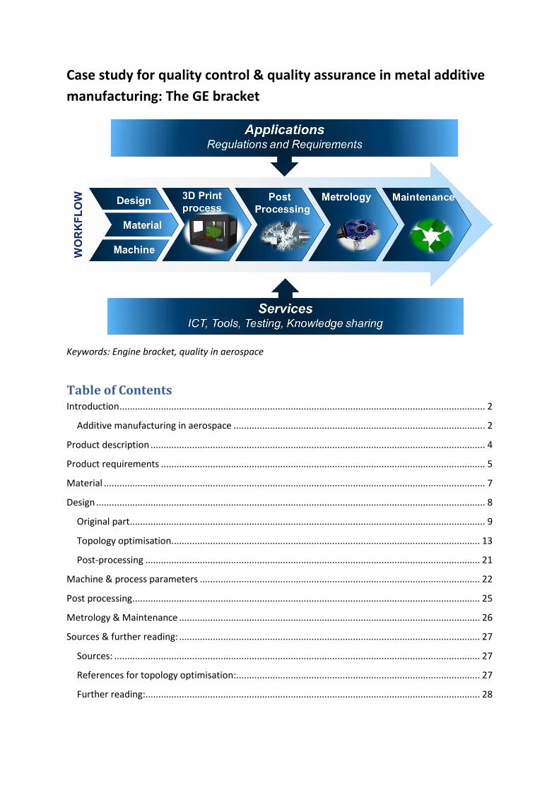
Case study for quality control & quality assurance in metal additive
manufacturing: The GE bracket
Keywords: Engine bracket, quality in aerospace
Table of Contents Introduction ............................................................................................................................................. 2
Additive manufacturing in aerospace ................................................................................................. 2
Product description ................................................................................................................................. 4
Product requirements ............................................................................................................................. 5
Material ................................................................................................................................................... 7
Design ...................................................................................................................................................... 8
Original part ......................................................................................................................................... 9
Topology optimisation ....................................................................................................................... 13
Post-processing ................................................................................................................................. 21
Machine & process parameters ............................................................................................................ 22
Post processing ...................................................................................................................................... 25
Metrology & Maintenance .................................................................................................................... 26
Sources & further reading: .................................................................................................................... 27
Sources: ............................................................................................................................................. 27
References for topology optimisation:.............................................................................................. 27
Further reading:................................................................................................................................. 28
Introduction
On the ManSYS website, quality in metal AM is discussed in relevance to the AM value chain. Quality
issues discussed in this value chain are relevant for metal AM in general and the value chain can be
used for different applications. In this chapter, we use of the AM value chain in an application driven
manner, for the fabrication of an aerospace bracket.
The structure of this chapter is similar to the AM value chain. First, requirements for the aerospace
bracket are defined. Following on the requirements, the AM workflow, including design, material,
process, post-processing and metrology is described and quality aspects are discussed.
Additive manufacturing in aerospace
In the early stages of the 30 years of AM’s deployment, the technology was largely geared toward
prototyping and tooling applications; however, in recent years, AM has found success in end-part
production, driven by improved manufacturability and reduced lead time compared to traditional
manufacturing methods.
The aerospace industry was an early adopter of AM technology, tracing back to 1983 and 1988
(Newsela, 2013). This early interest results today in a 10 percent share of global AM revenue
(Wohlers 2013). The aerospace has major incentives to adopt AM technology for the production of
aerospace part. Examples of benefits and incentives to invest in AM technology are the following
(Deloitte 2014, van Toor 2014):
Part cost down
Less waste
Less time to market
Part weight down
Buy-to-fly ratio 1:1
Less assembly
Less tooling
Whereas currently AM adoption in the aerospace industry comprises mainly non-flight critical parts,
such as armrests or parts of a stewards car, high quality AM produced products can be used for flight
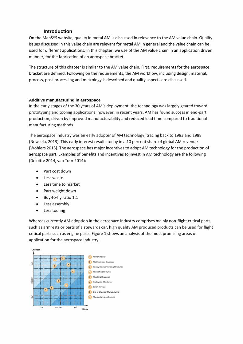
critical parts such as engine parts. Figure 1 shows an analysis of the most promising areas of
application for the aerospace industry.
Figure 1 Prioritizing innovation fields of the aerospace industry using a chances-risks-portfolio
(Gausemeier 2012)
Next to the AM fabrication of the GE bracket, which will be discussed in this chapter, the GE fuel
nozzle is an example of an AM manufactured flight critical part, with multiple benefits:
Lighter in weight – the weight of these nozzles will be 25% lighter than its predecessor part.
Simpler design – the number of parts used to make the nozzle will be reduced from 18 to 1.
New design features – more intricate cooling pathways and support ligaments will result in
5X higher durability vs. conventional manufacturing.
The production of 3D-printed parts in GE aircraft engines signals a paradigm shift that is happening
with the emergence of additive manufacturing (GE aviation, 3D printing new engine parts).
Quality of AM manufactured parts in aerospace
When AM commercialized in 2003, initially, a lack of process understanding and control resulted in
parts with poor mechanical performance. This prevented the technology to be used for applications
which required structural loading of the part (Kruth, 2013). Since then, AM technology made major
improvements over the years, resulting in much higher end product quality nowadays.
In markets as aerospace, where quality and reliability are a top priority, certification plays a major
role. Historically, certification of new aerospace materials and processes could take decades (Saha et
al, 2014). Lack of certification of the AM process nowadays, require that for high quality applications
not only standardisation, but also best case practices are highly relevant when adopting AM
technology.
Cases which describe quality, such as the GE bracket presented here, are therefore valuable.

Product description
As demonstrator part for aerospace the GE bracket is used. Loading brackets pay a very important
role within the engine of an airplay: they must support the weight of the engine during handling
without breaking or warping. The brackets may be used only periodically, but they stay on the engine
at all times, including during flight.
But these brackets aren’t the only parts on an engine that offer weight-reduction opportunities.
There are many similar load-carrying parts on the engine that, because they were designed for
conventional manufacturing technologies, are not fully optimized for both performance and weight.
By substantiating Additive Manufacturing in this particular case, we will enable significant weight
savings throughout the engine (grabcad.com/challenges/ge-jet-engine-bracket-challenge).
Product requirements
Material
These engine parts are made up of super alloys (Inconel and titanium alloys). In the project the
material of the bracket is Ti-6Al-4V, so the applicable standard is ASTM F2924-14 “Standard
Specification for Additive Manufacturing Titanium-6-Aluminium-4 Vanadium with Powder Bed
Fusion”.
Functional requirements
Service Temperature: 75 F
Minimum material feature size (wall thickness): 0.050 in.
Interface 1: 0.75 inch diameter pin. The pin is to be considered infinitely stiff.
Interfaces 2 – 5: 0.375-24 AS3239-26 machine bolt. Nut face 0.405 in. max ID and 0.558 in.
min OD. The bolts are to be considered infinitely stiff.
Load Conditions:
1. Max static linear load of 8,000 lbs vertical up.
2. Max static linear load of 8,500 lbs horizontal out.
3. Max static linear load of 9,500 lbs 42 degrees from vertical.
4. Max static torsional load of 5,000 lb-in horizontal at intersection of centerline of pin and midpoint
between clevis arms.
Assume yield strength is 131 ksi.
Surface roughness : 120 Ra
For internal and surface discontinuities assume:
Max allowable indication size for all discontinuity types is severity level 3 per ASTM E192 Table 1.
Max allowable surface porosity and other surface indications is 0.05” max diameter, with 0.2” min.
spacing. No linear indication greater than 0.04 inch is allowed.
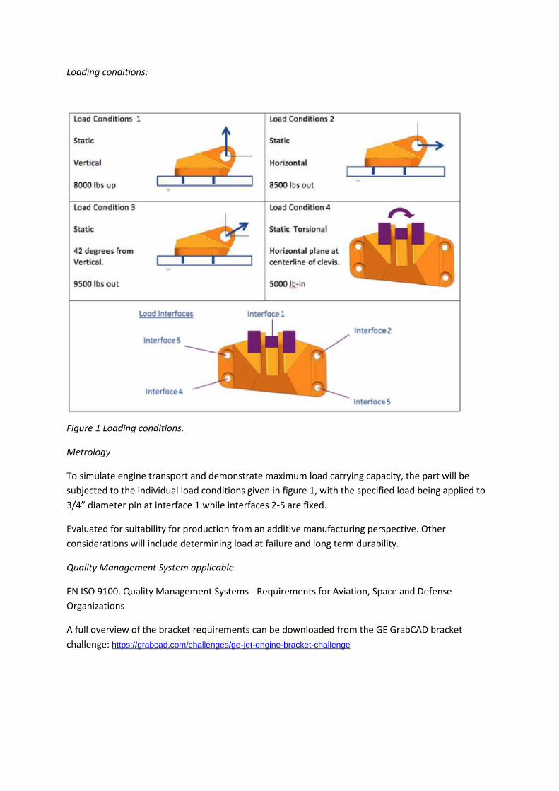
Loading conditions:
Figure 1 Loading conditions.
Metrology
To simulate engine transport and demonstrate maximum load carrying capacity, the part will be
subjected to the individual load conditions given in figure 1, with the specified load being applied to
3/4” diameter pin at interface 1 while interfaces 2-5 are fixed.
Evaluated for suitability for production from an additive manufacturing perspective. Other
considerations will include determining load at failure and long term durability.
Quality Management System applicable
EN ISO 9100. Quality Management Systems - Requirements for Aviation, Space and Defense
Organizations
A full overview of the bracket requirements can be downloaded from the GE GrabCAD bracket
challenge: https://grabcad.com/challenges/ge-jet-engine-bracket-challenge
Material
Requirements
Requirements for material consists of the following standard: ASTM F2924-14 “Standard
Specification for Additive Manufacturing Titanium-6-Aluminium-4 Vanadium with Powder Bed
Fusion”.
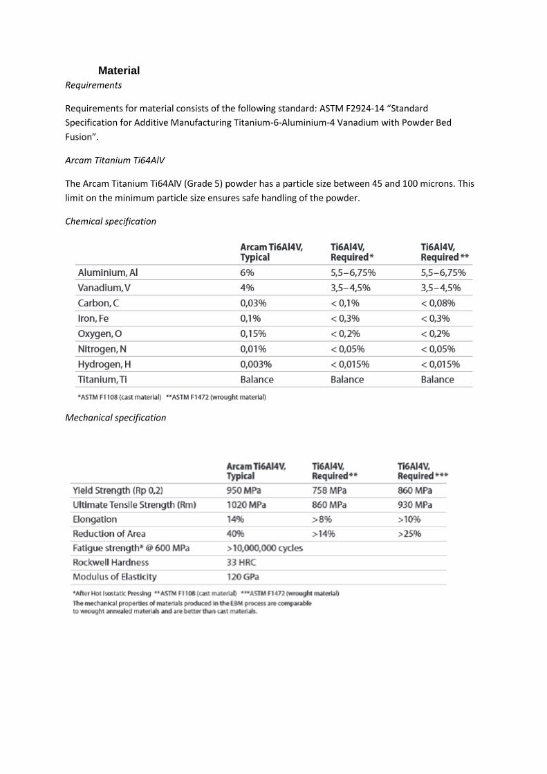
Arcam Titanium Ti64AlV
The Arcam Titanium Ti64AlV (Grade 5) powder has a particle size between 45 and 100 microns. This
limit on the minimum particle size ensures safe handling of the powder.
Chemical specification
Mechanical specification

Design
For design of the bracket, we use the structure, as presented in the AM value chain, considering of
four main steps and several sub-steps:
Original part
o Definition of geometry (CAD)
o Definition of load cases and constraints
o Part requirements
o Analysis of original component
Topology optimisation
o Optimisation parameters
o Assessment of results
o Assessment of mesh sensitivity study
Part re-design
o Materialise 3-Matic software
o Regularise, smooth, and replace unwanted aspects
o Re-mesh
o Add substructures
Final verification
o Re-mesh
o Analyse under design loads
o Verify adequacy of solution
Original part
Geometry
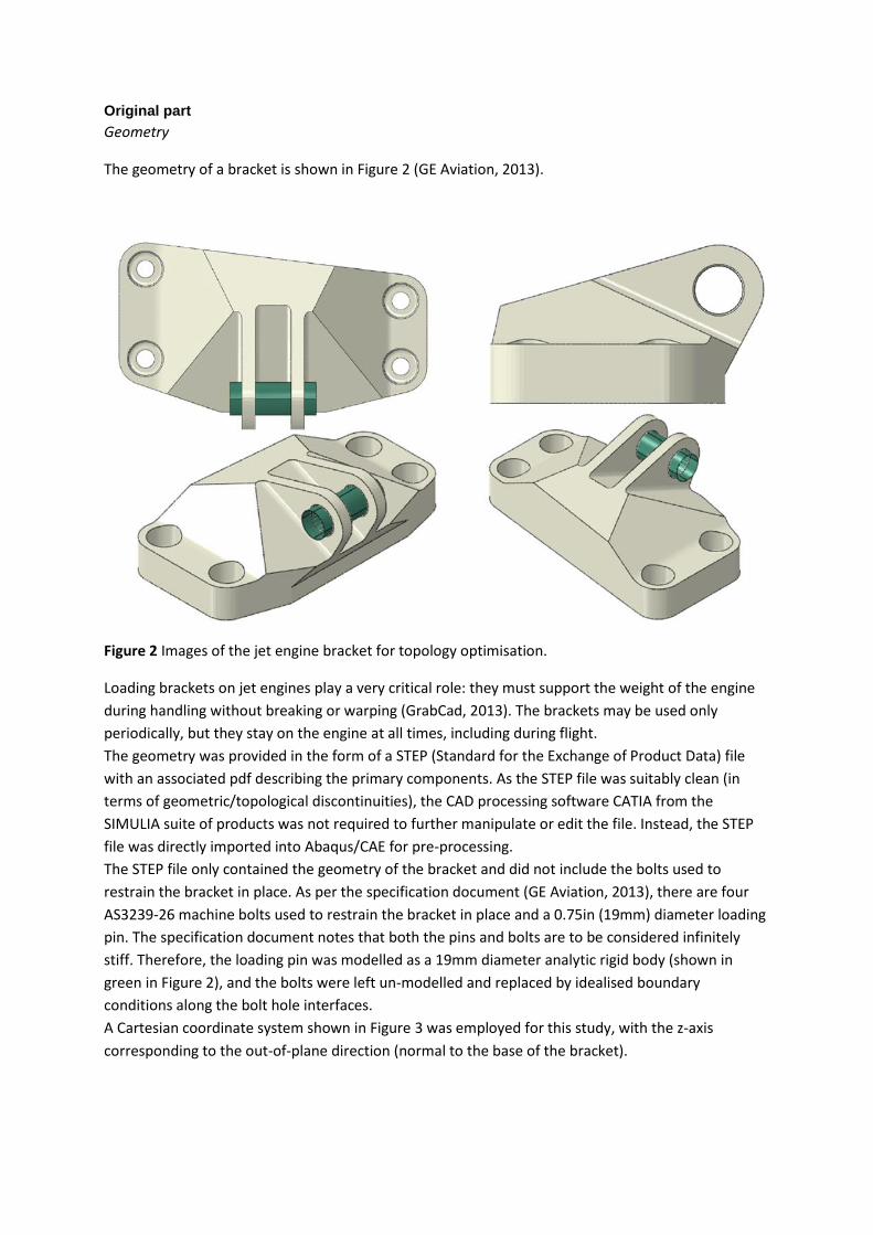
The geometry of a bracket is shown in Figure 2 (GE Aviation, 2013).
Figure 2 Images of the jet engine bracket for topology optimisation.
Loading brackets on jet engines play a very critical role: they must support the weight of the engine
during handling without breaking or warping (GrabCad, 2013). The brackets may be used only
periodically, but they stay on the engine at all times, including during flight.
The geometry was provided in the form of a STEP (Standard for the Exchange of Product Data) file
with an associated pdf describing the primary components. As the STEP file was suitably clean (in
terms of geometric/topological discontinuities), the CAD processing software CATIA from the
SIMULIA suite of products was not required to further manipulate or edit the file. Instead, the STEP
file was directly imported into Abaqus/CAE for pre-processing.
The STEP file only contained the geometry of the bracket and did not include the bolts used to
restrain the bracket in place. As per the specification document (GE Aviation, 2013), there are four
AS3239-26 machine bolts used to restrain the bracket in place and a 0.75in (19mm) diameter loading
pin. The specification document notes that both the pins and bolts are to be considered infinitely
stiff. Therefore, the loading pin was modelled as a 19mm diameter analytic rigid body (shown in
green in Figure 2), and the bolts were left un-modelled and replaced by idealised boundary
conditions along the bolt hole interfaces.
A Cartesian coordinate system shown in Figure 3 was employed for this study, with the z-axis
corresponding to the out-of-plane direction (normal to the base of the bracket).
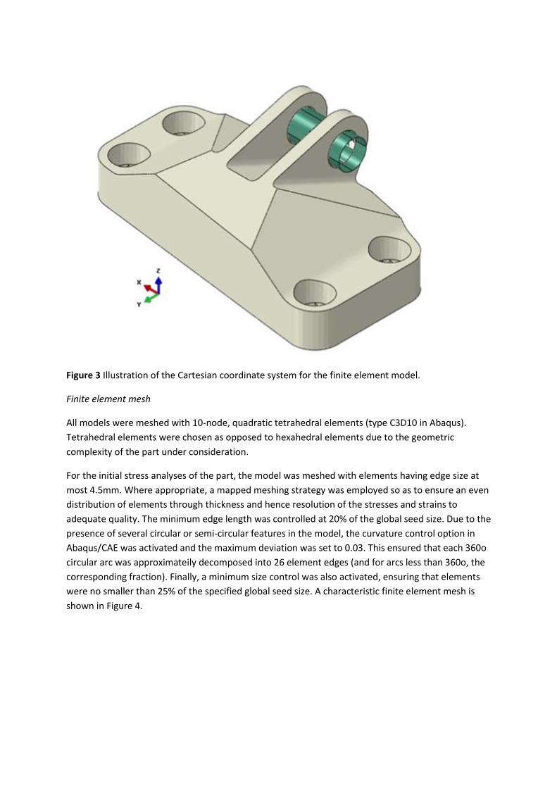
Figure 3 Illustration of the Cartesian coordinate system for the finite element model.
Finite element mesh
All models were meshed with 10-node, quadratic tetrahedral elements (type C3D10 in Abaqus).
Tetrahedral elements were chosen as opposed to hexahedral elements due to the geometric
complexity of the part under consideration.
For the initial stress analyses of the part, the model was meshed with elements having edge size at
most 4.5mm. Where appropriate, a mapped meshing strategy was employed so as to ensure an even
distribution of elements through thickness and hence resolution of the stresses and strains to
adequate quality. The minimum edge length was controlled at 20% of the global seed size. Due to the
presence of several circular or semi-circular features in the model, the curvature control option in
Abaqus/CAE was activated and the maximum deviation was set to 0.03. This ensured that each 360o
circular arc was approximateily decomposed into 26 element edges (and for arcs less than 360o, the
corresponding fraction). Finally, a minimum size control was also activated, ensuring that elements
were no smaller than 25% of the specified global seed size. A characteristic finite element mesh is
shown in Figure 4.
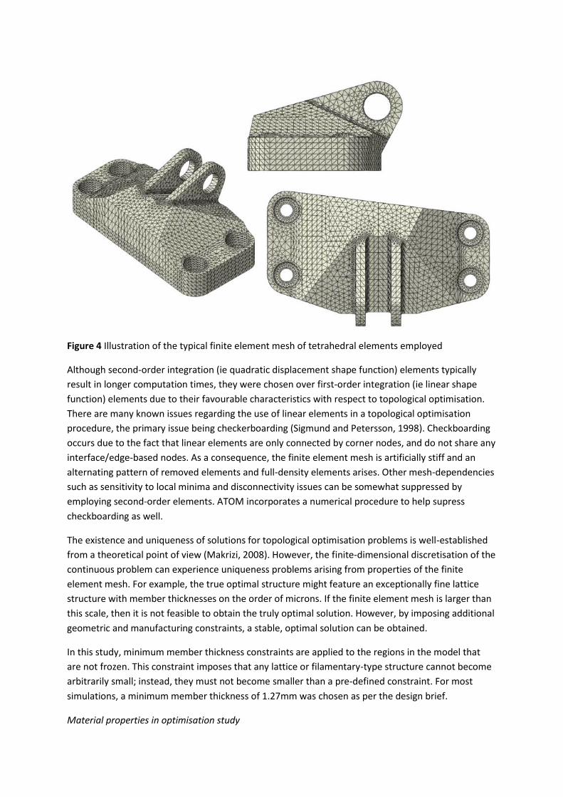
Figure 4 Illustration of the typical finite element mesh of tetrahedral elements employed
Although second-order integration (ie quadratic displacement shape function) elements typically
result in longer computation times, they were chosen over first-order integration (ie linear shape
function) elements due to their favourable characteristics with respect to topological optimisation.
There are many known issues regarding the use of linear elements in a topological optimisation
procedure, the primary issue being checkerboarding (Sigmund and Petersson, 1998). Checkboarding
occurs due to the fact that linear elements are only connected by corner nodes, and do not share any
interface/edge-based nodes. As a consequence, the finite element mesh is artificially stiff and an
alternating pattern of removed elements and full-density elements arises. Other mesh-dependencies
such as sensitivity to local minima and disconnectivity issues can be somewhat suppressed by
employing second-order elements. ATOM incorporates a numerical procedure to help supress
checkboarding as well.
The existence and uniqueness of solutions for topological optimisation problems is well-established
from a theoretical point of view (Makrizi, 2008). However, the finite-dimensional discretisation of the
continuous problem can experience uniqueness problems arising from properties of the finite
element mesh. For example, the true optimal structure might feature an exceptionally fine lattice
structure with member thicknesses on the order of microns. If the finite element mesh is larger than
this scale, then it is not feasible to obtain the truly optimal solution. However, by imposing additional
geometric and manufacturing constraints, a stable, optimal solution can be obtained.
In this study, minimum member thickness constraints are applied to the regions in the model that
are not frozen. This constraint imposes that any lattice or filamentary-type structure cannot become
arbitrarily small; instead, they must not become smaller than a pre-defined constraint. For most
simulations, a minimum member thickness of 1.27mm was chosen as per the design brief.
Material properties in optimisation study
As described in the demonstrator component briefing (GE Aviation, 2013), the bracket is to be made
of Ti-6Al-4V (also known as Grade 5). The brief specifies that the yield strength is assumed to be
131ksi (903MPa) and that the service temperature is 75oF (24oC). However, no additional information
about tensile properties is provided. Therefore, tensile properties for Grade 5 titanium alloy were
retrieved from the online materials database MatWeb (1997). Since a materials comparison was not
the focus of the study, it was not necessary to know the density of the titanium alloy. All of the
relevant tensile properties used in the analysis of the engine bracket are shown below in Table 1.
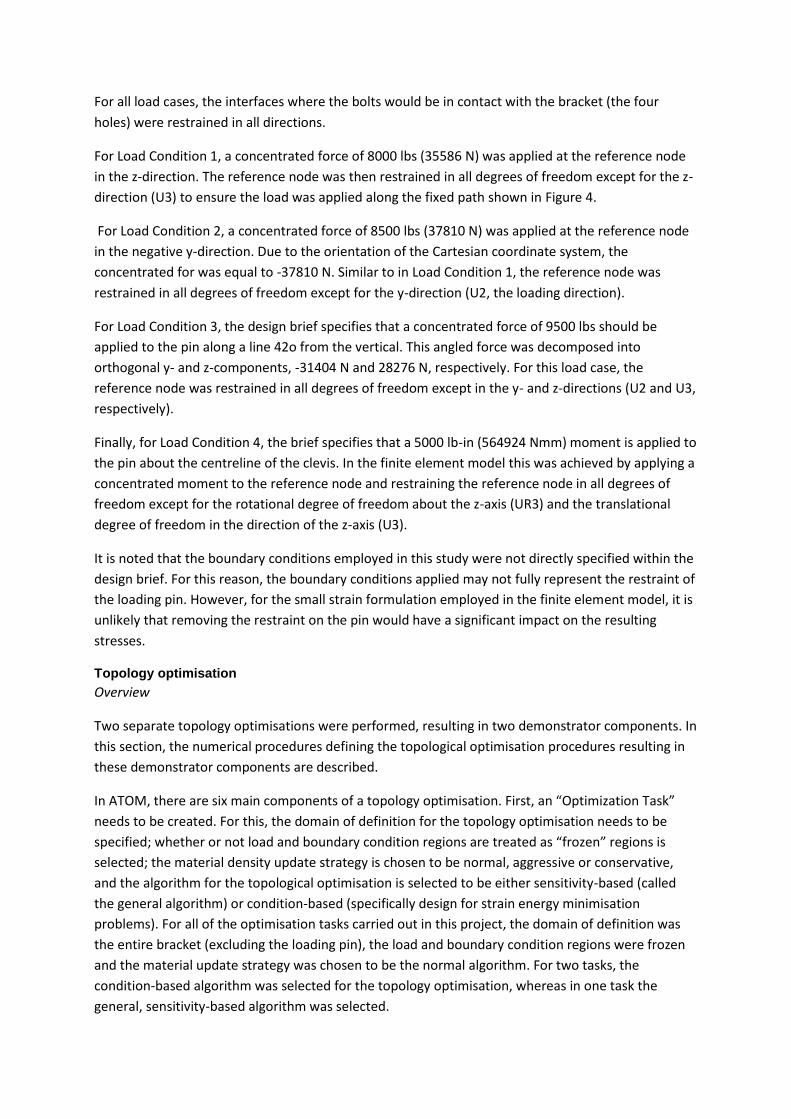
Table 1 Tensile properties for Ti-6Al-4V used in the optimisation study
Parameter Value Source
Youngs modulus (GPa) 113.8 MatWeb
Poisson’s ratio (MPa) 0.33 MatWeb
Yield stress (MPa) 903 Design brief
Loads and boundary conditions
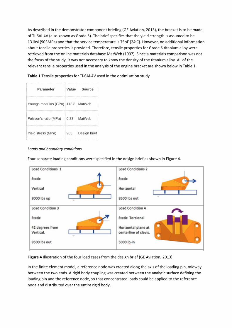
Four separate loading conditions were specified in the design brief as shown in Figure 4.
Figure 4 Illustration of the four load cases from the design brief (GE Aviation, 2013).
In the finite element model, a reference node was created along the axis of the loading pin, midway
between the two ends. A rigid body coupling was created between the analytic surface defining the
loading pin and the reference node, so that concentrated loads could be applied to the reference
node and distributed over the entire rigid body.
For all load cases, the interfaces where the bolts would be in contact with the bracket (the four
holes) were restrained in all directions.
For Load Condition 1, a concentrated force of 8000 lbs (35586 N) was applied at the reference node
in the z-direction. The reference node was then restrained in all degrees of freedom except for the z-
direction (U3) to ensure the load was applied along the fixed path shown in Figure 4.
For Load Condition 2, a concentrated force of 8500 lbs (37810 N) was applied at the reference node
in the negative y-direction. Due to the orientation of the Cartesian coordinate system, the
concentrated for was equal to -37810 N. Similar to in Load Condition 1, the reference node was
restrained in all degrees of freedom except for the y-direction (U2, the loading direction).
For Load Condition 3, the design brief specifies that a concentrated force of 9500 lbs should be
applied to the pin along a line 42o from the vertical. This angled force was decomposed into
orthogonal y- and z-components, -31404 N and 28276 N, respectively. For this load case, the
reference node was restrained in all degrees of freedom except in the y- and z-directions (U2 and U3,
respectively).
Finally, for Load Condition 4, the brief specifies that a 5000 lb-in (564924 Nmm) moment is applied to
the pin about the centreline of the clevis. In the finite element model this was achieved by applying a
concentrated moment to the reference node and restraining the reference node in all degrees of
freedom except for the rotational degree of freedom about the z-axis (UR3) and the translational
degree of freedom in the direction of the z-axis (U3).
It is noted that the boundary conditions employed in this study were not directly specified within the
design brief. For this reason, the boundary conditions applied may not fully represent the restraint of
the loading pin. However, for the small strain formulation employed in the finite element model, it is
unlikely that removing the restraint on the pin would have a significant impact on the resulting
stresses.
Topology optimisation
Overview
Two separate topology optimisations were performed, resulting in two demonstrator components. In
this section, the numerical procedures defining the topological optimisation procedures resulting in
these demonstrator components are described.
In ATOM, there are six main components of a topology optimisation. First, an “Optimization Task”
needs to be created. For this, the domain of definition for the topology optimisation needs to be
specified; whether or not load and boundary condition regions are treated as “frozen” regions is
selected; the material density update strategy is chosen to be normal, aggressive or conservative,
and the algorithm for the topological optimisation is selected to be either sensitivity-based (called
the general algorithm) or condition-based (specifically design for strain energy minimisation
problems). For all of the optimisation tasks carried out in this project, the domain of definition was
the entire bracket (excluding the loading pin), the load and boundary condition regions were frozen
and the material update strategy was chosen to be the normal algorithm. For two tasks, the
condition-based algorithm was selected for the topology optimisation, whereas in one task the
general, sensitivity-based algorithm was selected.
The second component of a topology optimisation is the “Definition of Design Responses”. ATOM
allows for a range of variables to be included in the optimisation, such as strain energy, volume,
weight, displacement, frequencies, moment of inertia and reaction forces. For each task, two design
responses were created: strain energy and volume. Since there are four different load cases to
consider, the strain energy was defined as the sum of the strain energy across all load cases.
The third component of a topology optimisation is to define the objective function. For all topology
optimisations carried out, the objective function was defined as the strain energy of the bracket
(across all load cases) with the target being to minimise the strain energy. No other objective
functions were considered in this study.
The fourth component is to define the optimisation constraints. ATOM allows the user to define
constraints on the design responses previously specified. For this study, volume was chosen as a
variable for constraint. Specifically, the volume was specified to be less than or equal to 20% or 25%
of the original part volume for the tasks described below.
The fifth component of a topology optimisation with ATOM is the “Geometric Restrictions Manager”.
This allows for the user to specify frozen areas (regions in which the material must remain invariant),
member size controls, and symmetry requirements, etc. The design brief specified that the minimum
material feature size (wall thickness) was 0.05 in (1.27 mm). Therefore for each of the topology
optimisation routines carried out, the member size control was specified to have a minimum
member thickness of 1.27 mm. The design brief also described that the interfaces (bolt holes and
loading pin interface) needed to remain fixed. Therefore, frozen regions were assigned in these
regions with the details provided for each case below. No other geometric restrictions were
considered.
Finally, the last component of a topology optimisation with ATOM is the definition of a “Stop
Condition”. A stopping condition is a criterion that, when met, causes the optimisation routine to
terminate. For example, if the stresses in the component exceed the yield stress of the material, then
a stopping condition can be defined to ensure that no further material redistribution occurs.
Additionally, the user can specify the number of iterations to carry out before the optimisation
terminates. However, if this number is too low, then the optimisation might terminate prematurely
without having satisfied the volume constraints or stopping criterion. In the optimisation routines
carried out for ManSYS, no stopping criterion was enforced; the results were checked a posteriori for
the suitability of the resulting designs.
Topology optimisation I
The first topology optimisation sought to reduce the overall volume of the component to be 25% of
the volume of the original design. The parameters for the topology optimisation are shown in Table
2.
Table 2 Definition of the topology optimisation parameters for topology optimisation I.
Domain of definition Entire part
Optimisation algorithm General, sensitivity-based
Target volume reduction 25% of original volume
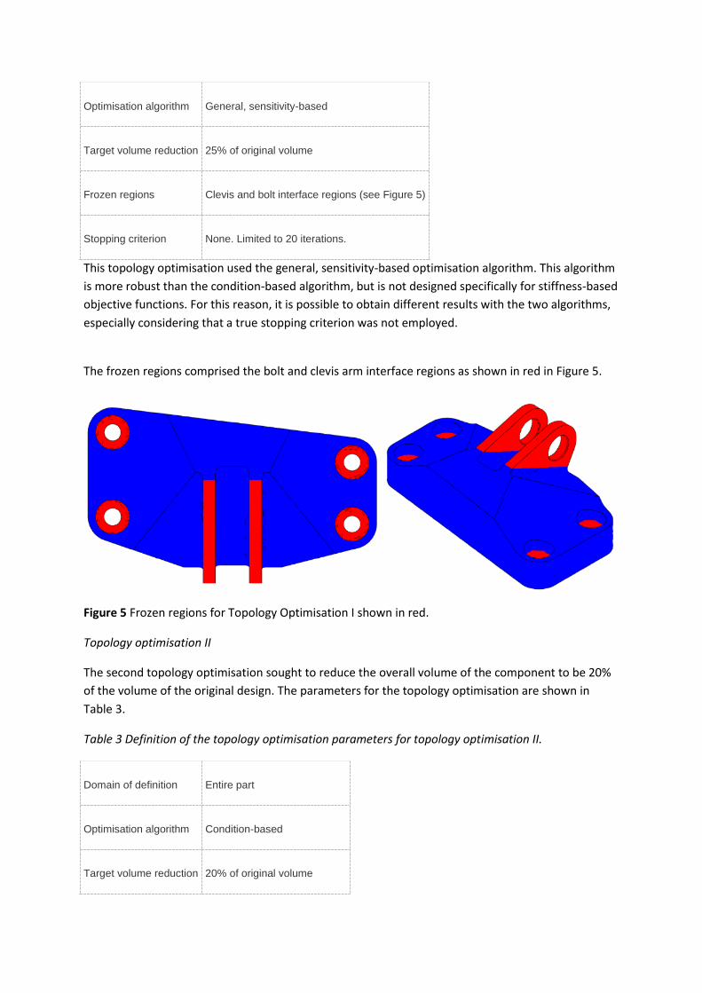
Frozen regions Clevis and bolt interface regions (see Figure 5)
Stopping criterion None. Limited to 20 iterations.
This topology optimisation used the general, sensitivity-based optimisation algorithm. This algorithm
is more robust than the condition-based algorithm, but is not designed specifically for stiffness-based
objective functions. For this reason, it is possible to obtain different results with the two algorithms,
especially considering that a true stopping criterion was not employed.
The frozen regions comprised the bolt and clevis arm interface regions as shown in red in Figure 5.
Figure 5 Frozen regions for Topology Optimisation I shown in red.
Topology optimisation II
The second topology optimisation sought to reduce the overall volume of the component to be 20%
of the volume of the original design. The parameters for the topology optimisation are shown in
Table 3.
Table 3 Definition of the topology optimisation parameters for topology optimisation II.
Domain of definition Entire part
Optimisation algorithm Condition-based
Target volume reduction 20% of original volume

Frozen regions Bolt connections only
Stopping criterion None. Limited to 25 iterations.
For this optimisation, the clevis arm region was not frozen (unlike with the other case). Additionally,
the condition-based algorithm was employed, which can result in slightly different results.
Results: stress analysis of original geometry
A preliminary stress analysis was carried out on the original geometry as imported from the STEP file
into Abaqus/CAE. This analysis was used to determine the levels of stress in the original component
design as well as to interpret the locations of low and high stresses in the model. This qualitative
assessment provides insight into where the material redistribution will occur during the topology
optimisation algorithms.
In Figure 6, the von Mises stress contour is shown for each of the four load cases. It can be seen that
the peak stresses are 628 MPa, 494 MPa, 468 MPa, and 881 MPa for load conditions 1, 2, 3 and 4,
respectively. These peak stresses all correspond to contact stresses between the pin and the clevis
arm. High contact stresses such as these are secondary in nature and do not necessarily contribute to
the failure of the component by plastic collapse. If a stress-based stopping criterion were to have
been employed in the topology optimisations, then the domain over which the stresses should be
checked would be defined outside of the contact region to ensure the simulation did not stop
prematurely.
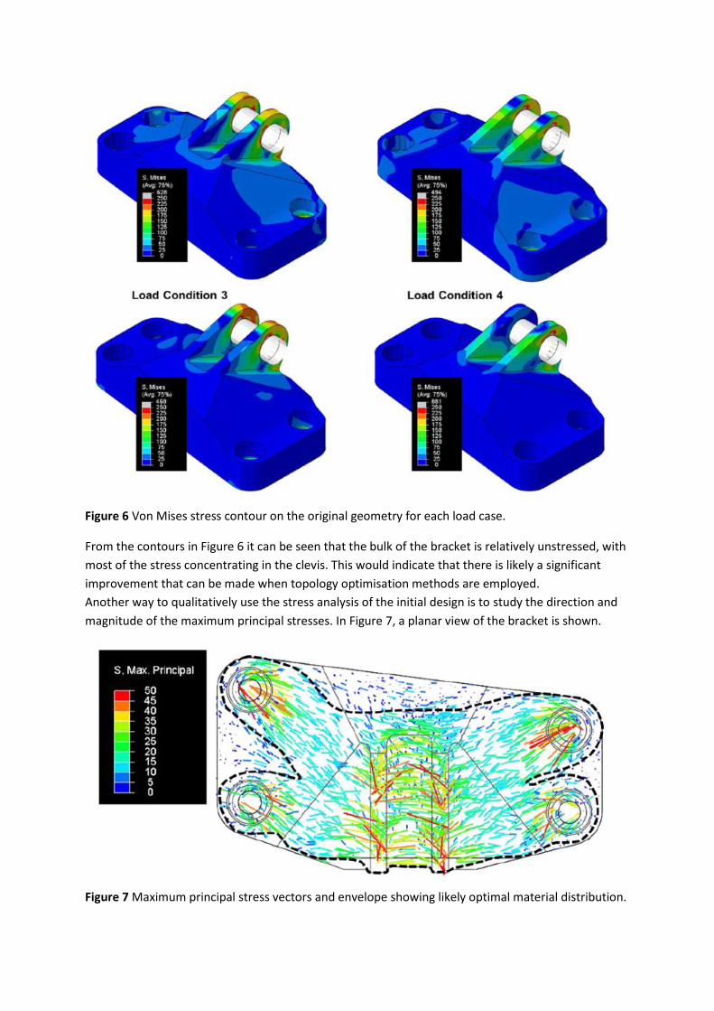
Figure 6 Von Mises stress contour on the original geometry for each load case.
From the contours in Figure 6 it can be seen that the bulk of the bracket is relatively unstressed, with
most of the stress concentrating in the clevis. This would indicate that there is likely a significant
improvement that can be made when topology optimisation methods are employed.
Another way to qualitatively use the stress analysis of the initial design is to study the direction and
magnitude of the maximum principal stresses. In Figure 7, a planar view of the bracket is shown.
Figure 7 Maximum principal stress vectors and envelope showing likely optimal material distribution.
At each mesh node, an arrow is drawn, with the direction of the arrow aligned with the direction of
maximum principal stress at the node, and the colour of the arrow corresponding to the magnitude
of principal stress. In Figure 7 there are some spurious peak stresses at the bolt holes and loading pin
interface (large red arrows). However, ignoring the spurious local stress concentrations, a dashed line
has been drawn, showing an envelope, approximately separating high stress regions from regions of
low stress. This type of assessment indicates where it is likely that material will be removed during
the topology optimisation (and can be seen from later results to provide a reasonable first
approximation of the ultimate part design).
Topology optimisation I
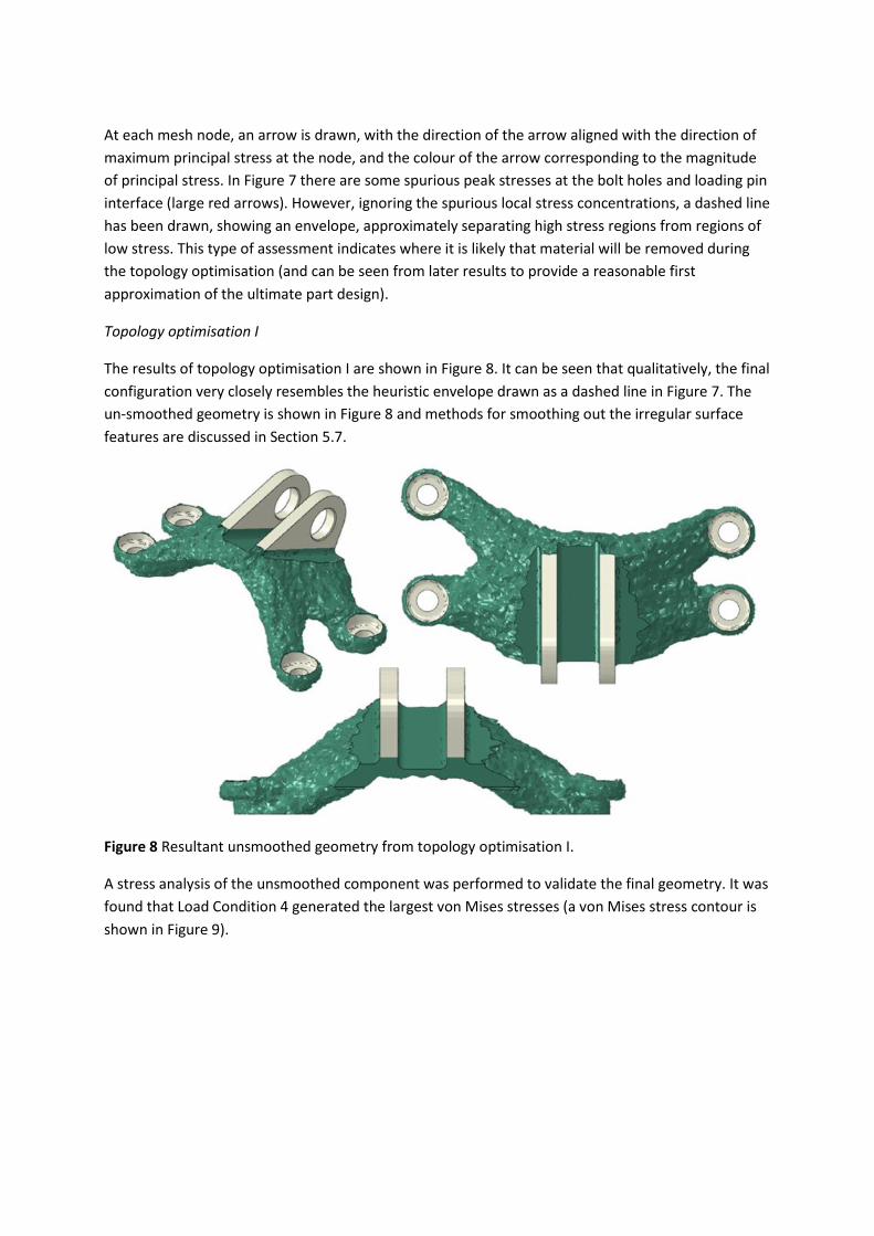
The results of topology optimisation I are shown in Figure 8. It can be seen that qualitatively, the final
configuration very closely resembles the heuristic envelope drawn as a dashed line in Figure 7. The
un-smoothed geometry is shown in Figure 8 and methods for smoothing out the irregular surface
features are discussed in Section 5.7.
Figure 8 Resultant unsmoothed geometry from topology optimisation I.
A stress analysis of the unsmoothed component was performed to validate the final geometry. It was
found that Load Condition 4 generated the largest von Mises stresses (a von Mises stress contour is
shown in Figure 9).
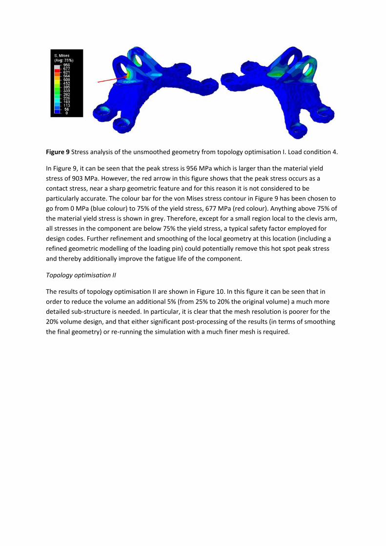
Figure 9 Stress analysis of the unsmoothed geometry from topology optimisation I. Load condition 4.
In Figure 9, it can be seen that the peak stress is 956 MPa which is larger than the material yield
stress of 903 MPa. However, the red arrow in this figure shows that the peak stress occurs as a
contact stress, near a sharp geometric feature and for this reason it is not considered to be
particularly accurate. The colour bar for the von Mises stress contour in Figure 9 has been chosen to
go from 0 MPa (blue colour) to 75% of the yield stress, 677 MPa (red colour). Anything above 75% of
the material yield stress is shown in grey. Therefore, except for a small region local to the clevis arm,
all stresses in the component are below 75% the yield stress, a typical safety factor employed for
design codes. Further refinement and smoothing of the local geometry at this location (including a
refined geometric modelling of the loading pin) could potentially remove this hot spot peak stress
and thereby additionally improve the fatigue life of the component.
Topology optimisation II
The results of topology optimisation II are shown in Figure 10. In this figure it can be seen that in
order to reduce the volume an additional 5% (from 25% to 20% the original volume) a much more
detailed sub-structure is needed. In particular, it is clear that the mesh resolution is poorer for the
20% volume design, and that either significant post-processing of the results (in terms of smoothing
the final geometry) or re-running the simulation with a much finer mesh is required.
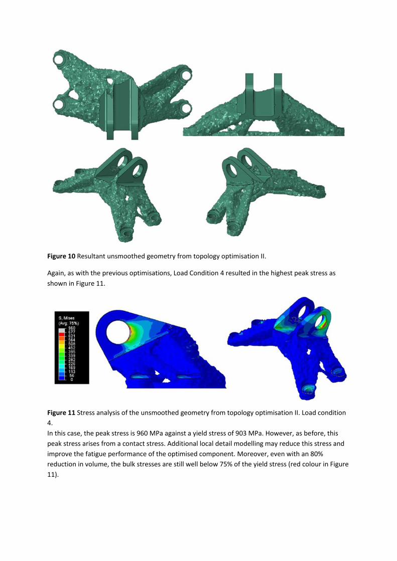
Figure 10 Resultant unsmoothed geometry from topology optimisation II.
Again, as with the previous optimisations, Load Condition 4 resulted in the highest peak stress as
shown in Figure 11.
Figure 11 Stress analysis of the unsmoothed geometry from topology optimisation II. Load condition
4.
In this case, the peak stress is 960 MPa against a yield stress of 903 MPa. However, as before, this
peak stress arises from a contact stress. Additional local detail modelling may reduce this stress and
improve the fatigue performance of the optimised component. Moreover, even with an 80%
reduction in volume, the bulk stresses are still well below 75% of the yield stress (red colour in Figure
11).
Post-processing
As noted from the topology optimisation simulations presented, the final geometry resulting from
the optimisation algorithms is “rough” in the sense that it is based on the initial tetrahedral finite
element mesh. Once a component has been optimised, the next step in the manufacturing supply
chain is for the analyst to supply the design in the form of an STL file (the standard AM file format) to
the manufacturer. However, any STL file extracted from the current geometries would not be
sufficiently smooth to provide to a manufacturer.
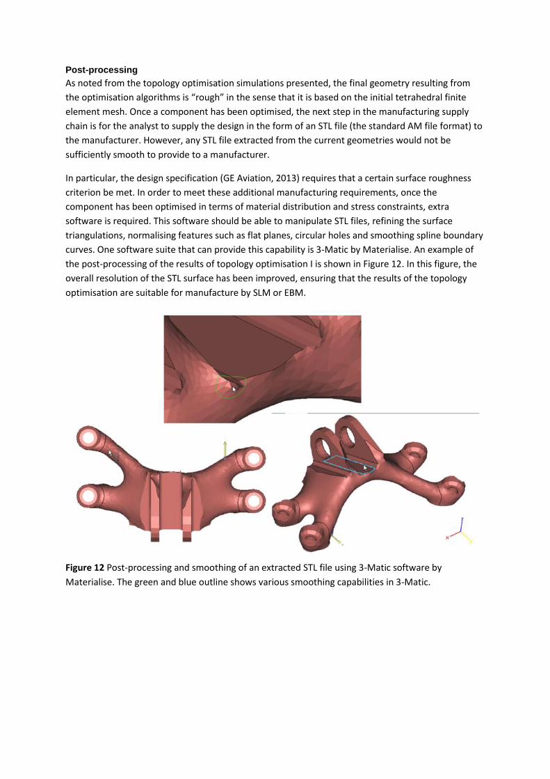
In particular, the design specification (GE Aviation, 2013) requires that a certain surface roughness
criterion be met. In order to meet these additional manufacturing requirements, once the
component has been optimised in terms of material distribution and stress constraints, extra
software is required. This software should be able to manipulate STL files, refining the surface
triangulations, normalising features such as flat planes, circular holes and smoothing spline boundary
curves. One software suite that can provide this capability is 3-Matic by Materialise. An example of
the post-processing of the results of topology optimisation I is shown in Figure 12. In this figure, the
overall resolution of the STL surface has been improved, ensuring that the results of the topology
optimisation are suitable for manufacture by SLM or EBM.
Figure 12 Post-processing and smoothing of an extracted STL file using 3-Matic software by
Materialise. The green and blue outline shows various smoothing capabilities in 3-Matic.

Machine & process parameters
SLM vs EBM
Chapter ‘applications’ compared SLM and EBM technology. For the production method of the
bracket, the EBM production method is preferred. Compared to SLM technology, EBM production
results in lower residual stress, and production is faster than with SLM.
Parameters to be controlled
The most important parameters to be controlled are shown in next figures. The EBM process has
particular parameters depending on the material, the layer thickness and during the different stages
of the procedure to build a part. The part is built on an Arcam EBM machine.
For Ti6Al4V and Ti6Al4V-ELI the following process parameters are used:
Melt point: 1168oC
Layer thickness: 0.05 mm-
Preheating parameters:
o General properties and square:
Preheating I
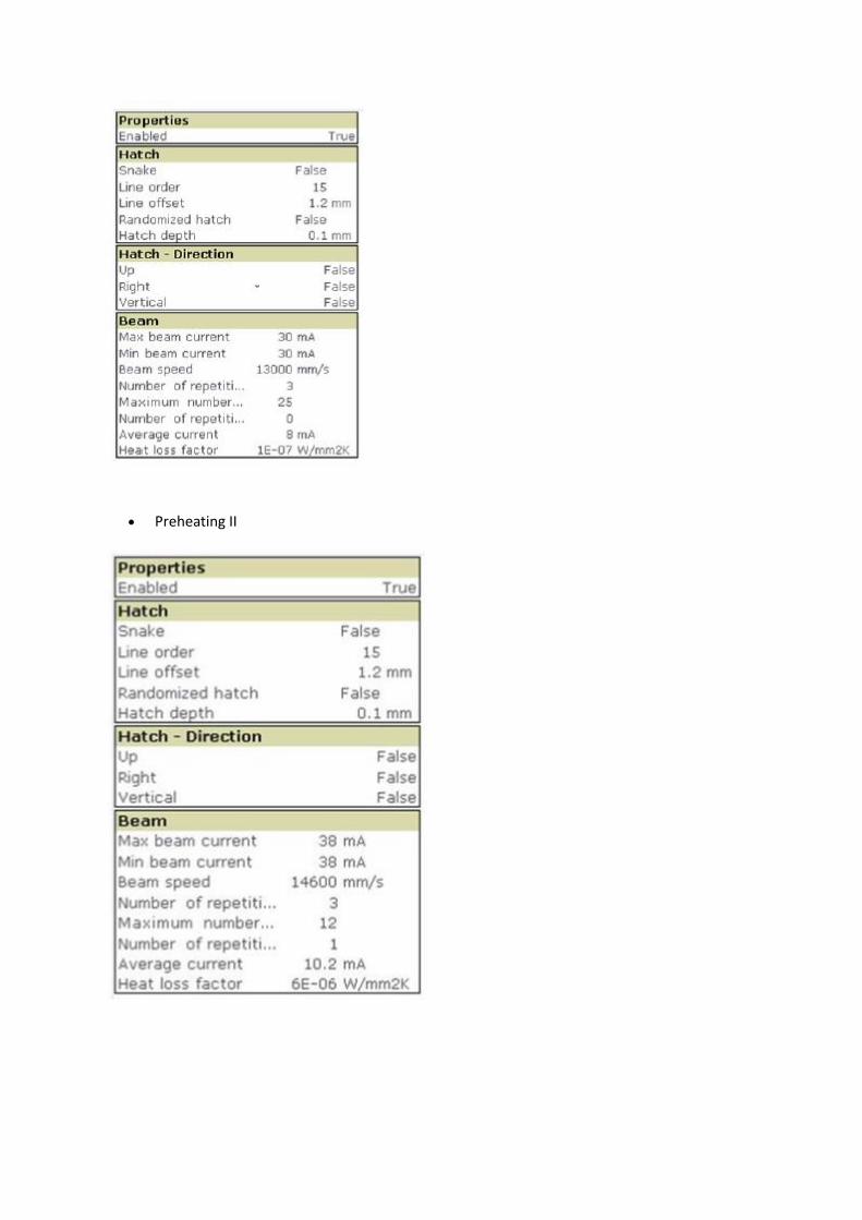
Preheating II
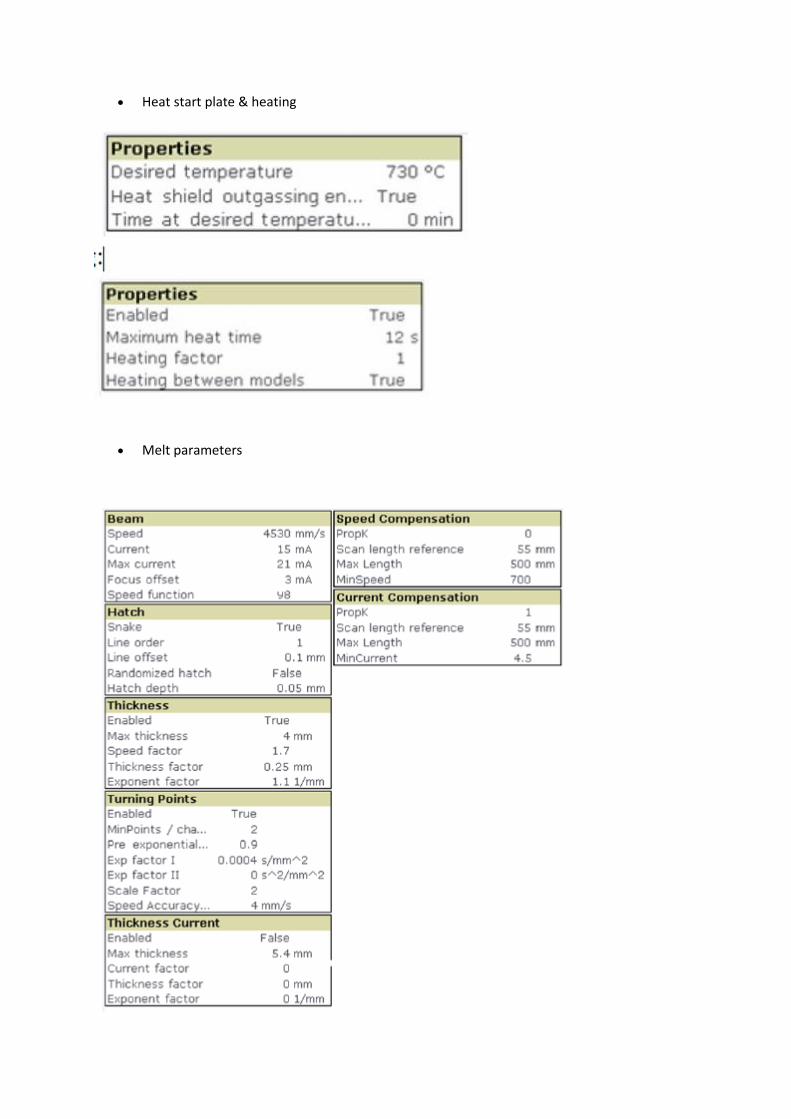
Heat start plate & heating
Melt parameters

Post processing
In order to obtain a final part it is necessary to develop these steps:
Remove part from the build platform
Remove supports
Sandblasting the surface
Clean the part to ensure that there is not dust
Machine the holes
Heat treatment: HIP (Hot Isostatic Pressure treatment) that is a post-process used to reduce
the porosity of metals and improves the material's mechanical properties (fatigue behavior)
and workability.

Metrology & Maintenance
The finished part must meet all the requirements stated in requirement: wall thickness, Load
Conditions, yield strength, surface roughness and surface porosity.
Test requirements are specified in ASTM E192. Standard Reference Radiographs of Investment Steel
Castings for Aerospace Applications. Other considerations will include determining load at failure and
long term durability.
Sources & further reading:
Sources:
3D opportunity in aerospace and defense, Deloitte University Press, 2014
B. Saha, R. J. H.Wanhill, N. E. Prasad, G. Gouda, and K. Tamilmani, Chapter 16 – Airworthiness
Certification of Metallic Materials, in Aluminum-lithium Alloys, edited by N. E. Prasad, A. A. Gokhale,
and R. J. H.Wanhill (Butterworth-Heinemann, Boston, 2014) pp. 537–554
GE aviation, 3D printing new engine parts, http://www.geglobalresearch.com/innovation/3d-
printing-creates-new-parts-aircraft-engines
J. Gausemeier, N. Echterhoff, andM.Wall, Thinking ahead the Future of AdditiveManufacturing –
Innovation Roadmapping of Required Advancements, Tech. Rep. (DMRC Paderborn, 2013).
J. Kruth, Survey of progress in Additive Manufacturing The Leuven experience 1990-2013, in 3D
Printing Event 2013 - Eindhoven (2013).
Newsela, “These 3-D printers use plastic and metal, not paper,” July 16, 2013,
http://www.newsela.com/articles/manufacturing-3d/id/563/, accessed December 27, 2013
Terry Wohlers, Wohlers report 2013: Additive manufacturing and 3D printing state of the industry
(2013)
Van Toor, A Knowledge Based System to support Design for Selective Laser Melting, TU Delft, 2014
References for topology optimisation:
Chahine G, Smith P and Kovacevic R (2010): ‘Application of topology optimization in modern additive
manufacturing’, Solid Freeform Fabrication Symposium, Austin, Texas, 2010.
Filippi S and Cristofolini I (2007): ‘The Design Guidelines (DGLs), a knowledge-based system for
industrial design developed accordingly to ISO-GPS (Geometrical Product Specifications) concepts’,
Research in Engineering Design, 18(1), pp 1-19
Gea HC and Luo J (2001): ‘Topology optimization of structures with geometrical nonlinearities’,
Computers and Structures, Vol 79, 2001.
GrabCad (2013): ‘GE jet engine bracket challenge’, https://grabcad.com/challenges/ge-jet-engine-
bracket-challenge retrieved 24 March 2014.
Gupta SK, Regli WC, Das D and Nau DS (1997): ‘Automated manufacturability analysis: a survey’,
Research in Engineering Design, 9(3), pp 168-190
Jung D and Gea HC (2004): ‘Topology optimization of nonlinear structures’, Finite elements in
analysis and design, Vol 40, 2004.
Kannan (2013): ‘Design for Additive Manufacturing’, Geometric Ltd. White Paper
Makrizi A (2008): ‘Solution of the topology optimization problem based subdomains method’,
Applied Mathematical Sciences, Vol 2, No 41, 2008.
Mallika A and Ramana Rao (2011): ‘Topology optimization of cylindrical shells for various support
conditions’, International Journal of Civil and Structural Engineering, Vol 2, No 1, 2011.
MatWeb (1997): ‘MatWeb: the online materials information resource. Christiansburg, VA:
Automation Creations Inc.
Ponche R, Hascoet JY, Kerbrat O and Mognol P (2012): ‘A new global approach to design for additive
manufacturing’, Virtual and Physical Prototyping, 7(2), 2012, pp 93-105.
Royden H and Fitzpatrick P (2010): ‘Real Analysis’, 4th Edition, Macmillan, New York, 2010.
Sambu S, Chen Y and Rosen DW (2004): ‘A design for manufacturing method for rapid prototyping
and rapid tooling’, Journal of Mechanical Design’, 126(4), pp 571-580.
Sigmund O and Petersson J (1998): ‘Numerical instabilities in topology optimization: A survey on
procedures dealing with checkerboards, mesh-dependencies and local minima’, Structural
Optimization, Vol 16.
SIMULIA, (2013): ‘Abaqus Documentation’, Version 6.13, Dassault Systèmes.
Teitelbaum GA (2009): ‘Proposed build guidelines for use in fused deposition modelling to reduce
build time and material volume’, Master of science in mechanical engineering, University of
Maryland, 2009.
Thomas D (2009): ‘The development of design rules for selective laser melting’, Dissertation for
Doctor of Philosophy for the University of Wales Institute, Cardiff
Further reading:
GrabCad (2013): ‘GE jet engine bracket challenge’,
Information on the GrabCad challenge, during which a competition was held to optimize the GE
bracket:
https://grabcad.com/challenges/ge-jet-engine-bracket-challenge
The GE Aircraft Engine Bracket Challenge: An Experiment in Crowdsourcing for Mechanical
Design Concepts
Scientific article on the GE grabcat challenge as a crowdsourcing experiment.
http://sffsymposium.engr.utexas.edu/sites/default/files/2014-110-Carter.pdf