Embed Size (px)
Citation preview
UML and Case Studies ITNP090 - Object Oriented Software Design
Dr Andrea BraccialiModule Co-ordinator
4B86 [email protected]
Dept. of Computing Science & MathematicsUniversity of Stirling
2
Case studies: OutlineI. Automated Banking System
Requirements Engineering: OO and incremental software development
1. case study: withdraw moneya. use casesb. identifying class/object (class diagram) c. interaction diagrams: sequence diagramsd. GUIs & CRC cards
2. case study: depositing moneya. sequence diagram (class diagram)b. communication diagram
Analysis and Design
Pre- post- conditions, design by contract
II. LibraryIII. Noughts and Crosses
Dept. of Computing Science & MathematicsUniversity of Stirling
3
Case Study: Automated Banking System
We are going to look at UML (Unified Modelling Language) by using a case study of an Automated Banking System:
Clients may take money from their accounts, deposit money or ask for their current balance.
All these operations are accomplished using either automatic teller machines (ATM) or counter tellers.
Transactions on an account may be done by cheque, standing order or using the teller machine and card.
There are two kinds of account: savings accounts and chequing accounts.
Savings accounts give interest and cannot be accessed by the automatic tellers.
When a cheque is deposited it must be cleared before the funds can be used by the depositor.
Dept. of Computing Science & MathematicsUniversity of Stirling
4
Requirement Engineering
Initial informal requirements are usually vague, inconsistent and incomplete. The purpose of requirements engineering is to clarify the requirements. Problems that can arise are:
– Different users may have conflicting needs.– Users do not always clearly state what they need. They may just
repeat what an existing (manual) system does.– Difficult to visualise how a system works in practice until you have
actually used it.– The managers who talk to the developers may have no direct
experience of actually using the system.
Dept. of Computing Science & MathematicsUniversity of Stirling
5
Use case model
Object-oriented development methods usually take a user-oriented approach to system development.
We identify the users of the system and the tasks that they requirethe system to perform.
UML uses the term actor. An actor is the role played by a user.
A user may interact with the system in more than one role and hence be represented by more than one actor.
For example, if a bank clerk withdraws money from an ATM, they are playing the role of an ordinary customer and are treated in our model as an ordinary customer.
Dept. of Computing Science & MathematicsUniversity of Stirling
6
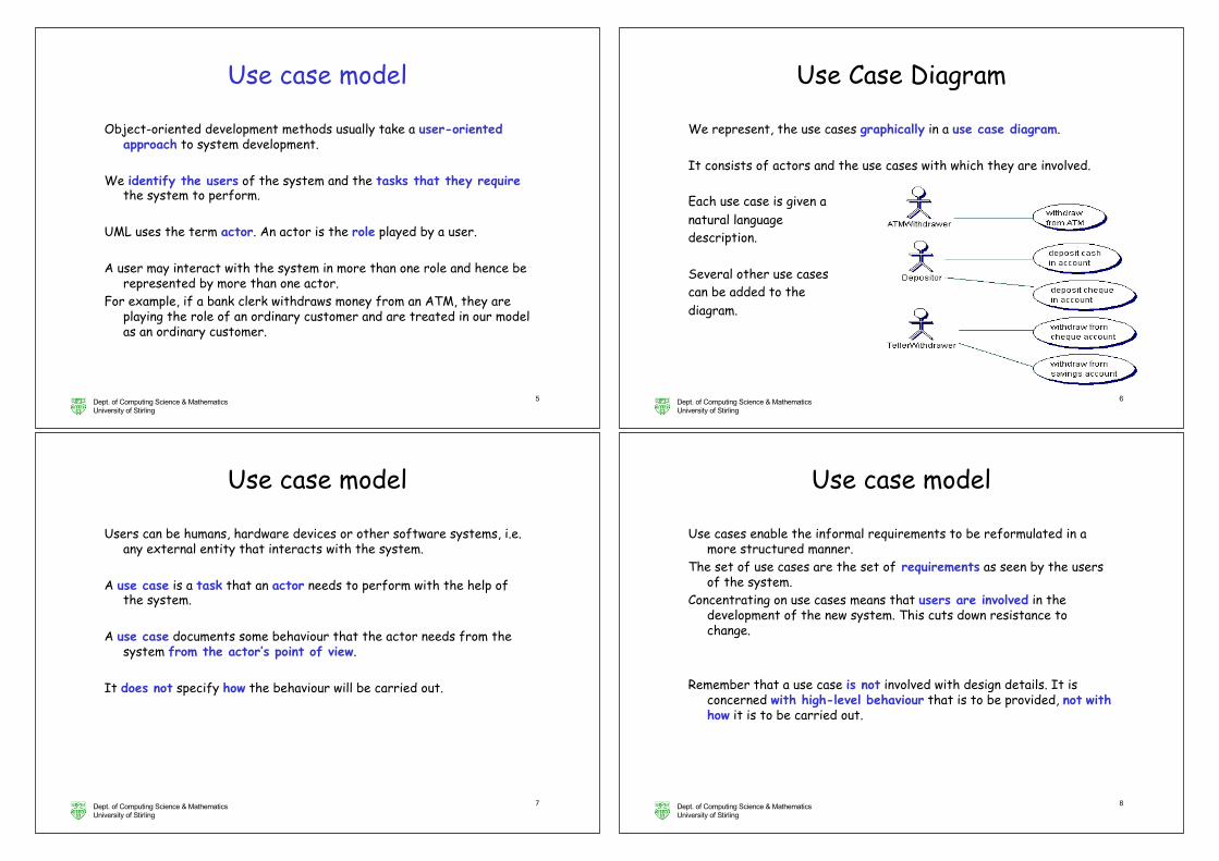
Use Case Diagram
We represent, the use cases graphically in a use case diagram.
It consists of actors and the use cases with which they are involved.
Each use case is given a natural language description.
Several other use cases can be added to the diagram.
Dept. of Computing Science & MathematicsUniversity of Stirling
7
Use case model
Users can be humans, hardware devices or other software systems, i.e. any external entity that interacts with the system.
A use case is a task that an actor needs to perform with the help of the system.
A use case documents some behaviour that the actor needs from the system from the actor’s point of view.
It does not specify how the behaviour will be carried out.
Dept. of Computing Science & MathematicsUniversity of Stirling
8
Use case model
Use cases enable the informal requirements to be reformulated in a more structured manner.
The set of use cases are the set of requirements as seen by the users of the system.
Concentrating on use cases means that users are involved in the development of the new system. This cuts down resistance to change.
Remember that a use case is not involved with design details. It is concerned with high-level behaviour that is to be provided, not withhow it is to be carried out.
Dept. of Computing Science & MathematicsUniversity of Stirling
9
Example use case
An example of a use case is withdraw money from ATM.
A use case can involve quite complex behaviour.
Each use case is documented in natural language.
The textual description of the use case is written in terms of what the user expects the system to do rather than as a passive description of what has to be done.
Dept. of Computing Science & MathematicsUniversity of Stirling
10
Withdraw money from ATM
An ATMwithdrawer inserts a card in an ATM and types in a PIN number. The system checks that the PIN matches the card.
If it does not, the system rejects the card.
If valid, the ATMwithdrawer types in the amount to be withdrawn.
The system checks that the account has sufficient funds.
If it does, the system debits the account and gives the money.
Otherwise, the system refuses the transaction.
Dept. of Computing Science & MathematicsUniversity of Stirling
11
Use casesIn constructing use cases, we should only put in what the users have
told us.However, the process of creating the use cases is likely to give us ideas
on how the system can be improved / extended.These should act as the basis for questions to the users, rather than be
added directly to the use cases.
In developing our model, it is best to concentrate on only a subset of the use cases. Others can be added later.
It is important to note that there is not a single correct model; different groups may arrive at different solutions, each of which is acceptable.
Creating good models is not easy; we seldom (never) get it right first time.
Dept. of Computing Science & MathematicsUniversity of Stirling
12
Use cases and validation
Each use case will be realised by one or more UML diagrams.
The use cases help us construct these diagrams.
Once we have a model, it is important to ensure that it satisfies the requirements -- called validation.
Use cases are important in determining the set of test cases to be used in validation.
Dept. of Computing Science & MathematicsUniversity of Stirling
13
Identifying classes
The next step is identifying the classes (or the objects, at this level of abstraction).
As a first step, we can take our informal requirements and identify the nounsor noun phrases, i.e. identify the words that potentially represent thingsin our system.
In the description on the next slide, the nouns and noun phrases are in bold italics.
Dept. of Computing Science & MathematicsUniversity of Stirling
14
Identifying classes
Clients may take money from their accounts, deposit money or ask for their current balance.
All these operations are accomplished using either automatic teller machines (ATM) or counter tellers.
Transactions on an account may be done by cheque, standing order or using the teller machine and card.
There are two kinds of account: savings accounts and chequing accounts.
Savings accounts give interest and cannot be accessed by the automatic tellers.
When a cheque is deposited it must be cleared before the funds can be used by the depositor.
Dept. of Computing Science & MathematicsUniversity of Stirling
15
Identifying classes
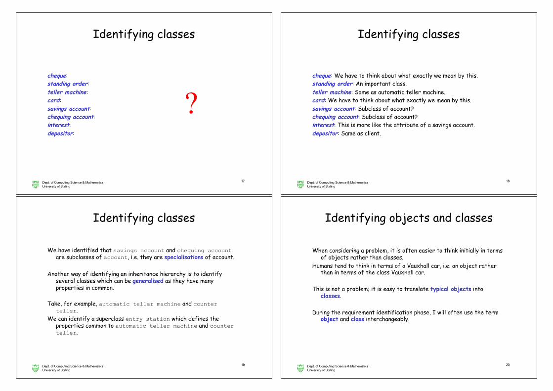
This gives us an initial set of potential classes. Let us consider each in turn:
Client:
money: account: current balance: automatic teller machine: counter teller:
?
Dept. of Computing Science & MathematicsUniversity of Stirling
16
Identifying classes
This gives us an initial set of potential classes. Let us consider each in turn:
Client: We could discard this because it is an actor. However, we may need to hold information about clients.
money: This is more like the attribute of an account.account: An important class.current balance: This is more like the attribute of an account.automatic teller machine: An important class.counter teller: An important class.
Dept. of Computing Science & MathematicsUniversity of Stirling
17
Identifying classes
cheque: standing order: teller machine: card: savings account: chequing account: interest: depositor:
?
Dept. of Computing Science & MathematicsUniversity of Stirling
18
Identifying classes
cheque: We have to think about what exactly we mean by this.standing order: An important class.teller machine: Same as automatic teller machine.card: We have to think about what exactly we mean by this.savings account: Subclass of account?chequing account: Subclass of account?interest: This is more like the attribute of a savings account.depositor: Same as client.
Dept. of Computing Science & MathematicsUniversity of Stirling
19
Identifying classes
We have identified that savings account and chequing accountare subclasses of account, i.e. they are specialisations of account.
Another way of identifying an inheritance hierarchy is to identify several classes which can be generalised as they have many properties in common.
Take, for example, automatic teller machine and counter teller.
We can identify a superclass entry station which defines the properties common to automatic teller machine and counter teller.
Dept. of Computing Science & MathematicsUniversity of Stirling
20
Identifying objects and classes
When considering a problem, it is often easier to think initially in terms of objects rather than classes.
Humans tend to think in terms of a Vauxhall car, i.e. an object rather than in terms of the class Vauxhall car.
This is not a problem; it is easy to translate typical objects into classes.
During the requirement identification phase, I will often use the term object and class interchangeably.
Dept. of Computing Science & MathematicsUniversity of Stirling
21
Identifying objects and classes
Some objects are fairly easy to identify, while others are more difficult.
Identifying nouns in the informal requirements is a good way of identifying domain objects, i.e. objects that belong to the problem.
There are two kinds of domain object: entity objects that hold information about entities in the problem domain and boundary objects through which we interact with the outside world.
Hence, Account is an entity class while ATM is a boundary class.They are the easiest kind of object to identify.
Dept. of Computing Science & MathematicsUniversity of Stirling
22
Identifying objects and classes
Other objects are created to help with the solution.
They can be much harder to identify.
An example is control objects that are created to co-ordinate some process after which they terminate themselves.
We will see later how sequence diagrams can help in the identification of control objects.
Dept. of Computing Science & MathematicsUniversity of Stirling
23
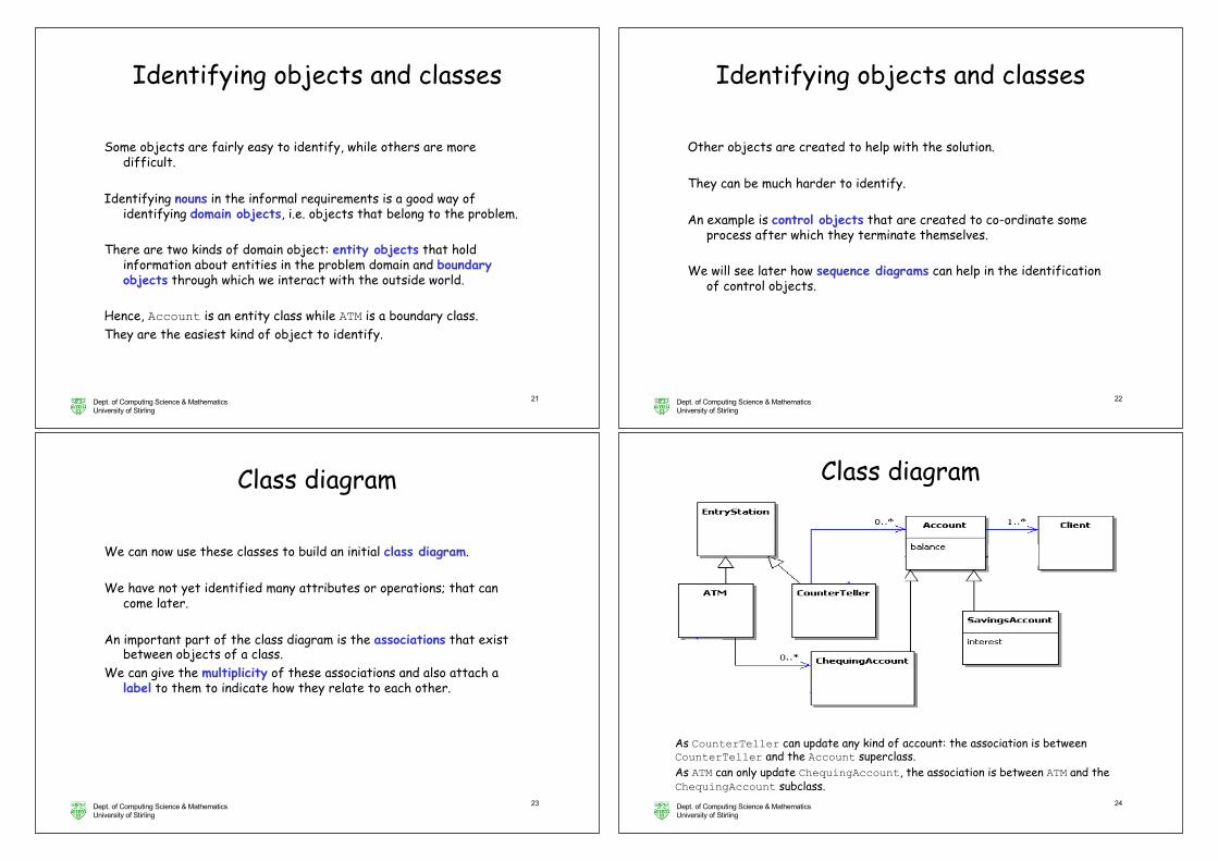
Class diagram
We can now use these classes to build an initial class diagram.
We have not yet identified many attributes or operations; that can come later.
An important part of the class diagram is the associations that exist between objects of a class.
We can give the multiplicity of these associations and also attach a label to them to indicate how they relate to each other.
Dept. of Computing Science & MathematicsUniversity of Stirling
24
Class diagram
As CounterTeller can update any kind of account: the association is between CounterTeller and the Account superclass.As ATM can only update ChequingAccount, the association is between ATM and the ChequingAccount subclass.
Dept. of Computing Science & MathematicsUniversity of Stirling
25
Early stage modelling process
In the early stages of analysis, it is best to create a class diagram in parallel with the use cases.
The initial class diagram will consist of classes defining objects from the problem domain.
The description of the use cases will often refer to such entities; it is therefore important to always use the same name for the same thing.
The initial class diagram can be where such names are defined.Also, use cases are not themselves object-oriented; relating them to
the initial class diagram helps keep our focus on objects.
Dept. of Computing Science & MathematicsUniversity of Stirling
26
Analysis models
The classes that we have represented in the class diagram all belong to the real world.
In fact object models can be used to model real world situations where there is no intention of creating software.
However, in this course, we must always bear in mind that the eventual aim is to create a software system (or a mixture of hardware and software).
In the requirements analysis phase, our main aim is to understand the problem.
Dept. of Computing Science & MathematicsUniversity of Stirling
27
Analysis models
As modelling is difficult, we do not want to get bogged down in detail.We therefore do not worry initially about whether an object is
hardware, software or really part of the environment.
Once we have created our initial model, we can explicitly attempt the difficult task of determining the boundary between the system and the environment.
Dept. of Computing Science & MathematicsUniversity of Stirling
28
Case studies: OutlineI. Automated Banking System
Requirements Engineering: OO and incremental software development
1. case study: withdraw moneya. use casesb. identifying class/object (class diagram) c. interaction diagrams: sequence diagramsd. GUIs & CRC cards
2. case study: depositing moneya. sequence diagram (class diagram)b. communication diagram
Analysis and Design
Inheritance, pre- post- conditions, design by contract
II. LibraryIII. Noughts and Crosses
Dept. of Computing Science & MathematicsUniversity of Stirling
31
Interaction diagrams
The class diagram shows the static structure of the system, but does not show its dynamic behaviour, i.e. how objects interact to carry out some task.
UML has interaction diagrams to show how objects can communicate with one another.
We consider here two kinds of interaction diagram:
– sequence diagrams and – communication diagrams (previously known as collaboration diagrams).
Here we show how sequence diagrams can represent scenarios, i.e. sequences of events which show a particular system behaviour.
Dept. of Computing Science & MathematicsUniversity of Stirling
32
Interaction diagrams
Sequence diagrams can be useful to:
• better understand and specify what may happen in a use case.• help us identify the operations offered by each object.• help us identify new classes that are required to support the
behaviour.
As interaction diagrams are dealing with behaviour, they are presented in terms of objects rather than classes (interaction happens through method calls).
Dept. of Computing Science & MathematicsUniversity of Stirling
33
Interaction diagrams
We can represent an object of class ATM as theATM:ATM.We always underline objects in a diagram to emphasise their difference
from classes.
Typically we want to indicate a typical object of a class. This can be represented as :ATM.
We will show the sequence diagram for successful withdrawal of money at an ATM. This use case has already been given.
Dept. of Computing Science & MathematicsUniversity of Stirling
34
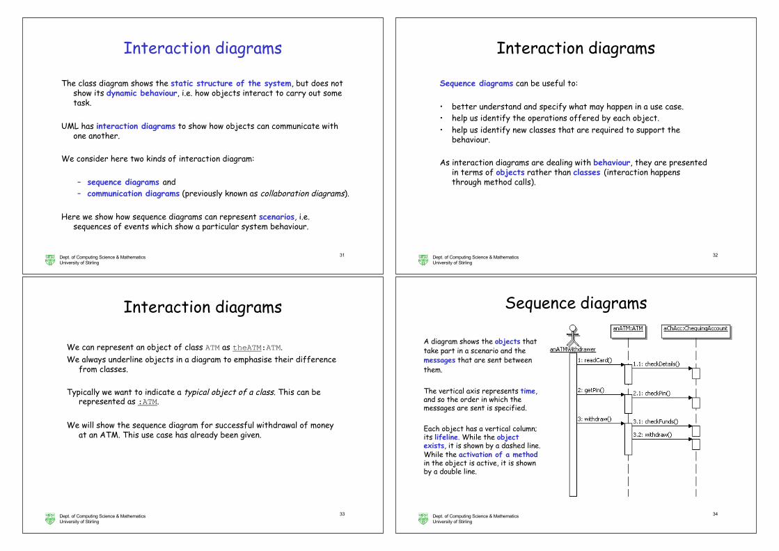
Sequence diagrams
A diagram shows the objects that take part in a scenario and the messages that are sent between them.
The vertical axis represents time, and so the order in which the messages are sent is specified.
Each object has a vertical column; its lifeline. While the object exists, it is shown by a dashed line. While the activation of a methodin the object is active, it is shown by a double line.
Dept. of Computing Science & MathematicsUniversity of Stirling
35
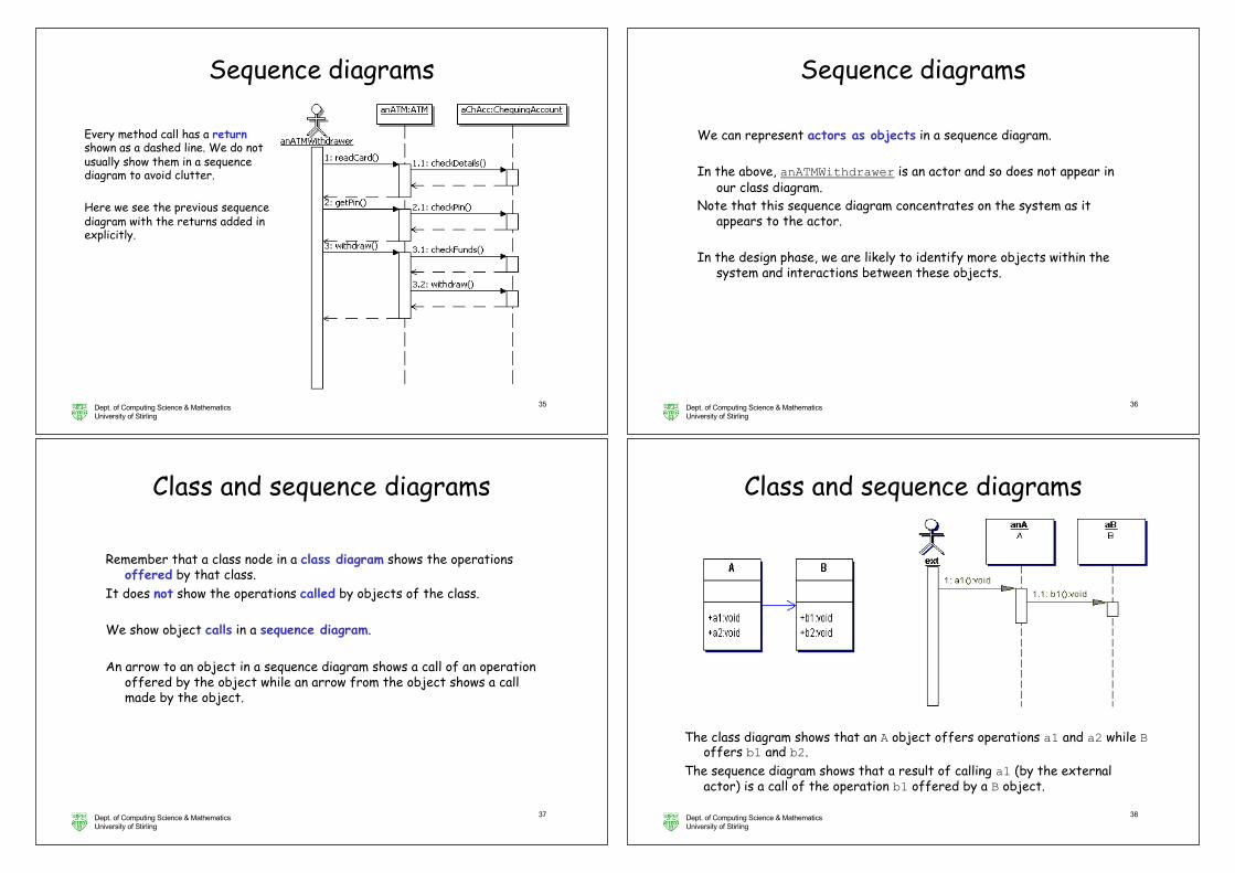
Every method call has a returnshown as a dashed line. We do not usually show them in a sequence diagram to avoid clutter.
Here we see the previous sequence diagram with the returns added in explicitly.
Sequence diagrams
Dept. of Computing Science & MathematicsUniversity of Stirling
36
We can represent actors as objects in a sequence diagram.
In the above, anATMWithdrawer is an actor and so does not appear in our class diagram.
Note that this sequence diagram concentrates on the system as it appears to the actor.
In the design phase, we are likely to identify more objects within the system and interactions between these objects.
Sequence diagrams
Dept. of Computing Science & MathematicsUniversity of Stirling
37
Class and sequence diagrams
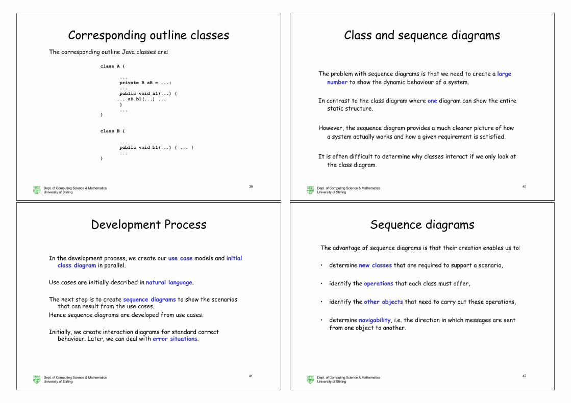
Remember that a class node in a class diagram shows the operations offered by that class.
It does not show the operations called by objects of the class.
We show object calls in a sequence diagram.
An arrow to an object in a sequence diagram shows a call of an operation offered by the object while an arrow from the object shows a call made by the object.
Dept. of Computing Science & MathematicsUniversity of Stirling
38
The class diagram shows that an A object offers operations a1 and a2 while Boffers b1 and b2.
The sequence diagram shows that a result of calling a1 (by the external actor) is a call of the operation b1 offered by a B object.
Class and sequence diagrams
Dept. of Computing Science & MathematicsUniversity of Stirling
39
Corresponding outline classesThe corresponding outline Java classes are:
class A {
...private B aB = ...;...public void a1(...) {... aB.b1(...) ...}...
}
class B {
...public void b1(...) { ... }...
}
Dept. of Computing Science & MathematicsUniversity of Stirling
40
The problem with sequence diagrams is that we need to create a large number to show the dynamic behaviour of a system.
In contrast to the class diagram where one diagram can show the entire static structure.
However, the sequence diagram provides a much clearer picture of how a system actually works and how a given requirement is satisfied.
It is often difficult to determine why classes interact if we only look at the class diagram.
Class and sequence diagrams
Dept. of Computing Science & MathematicsUniversity of Stirling
41
Development Process
In the development process, we create our use case models and initial class diagram in parallel.
Use cases are initially described in natural language.
The next step is to create sequence diagrams to show the scenarios that can result from the use cases.
Hence sequence diagrams are developed from use cases.
Initially, we create interaction diagrams for standard correct behaviour. Later, we can deal with error situations.
Dept. of Computing Science & MathematicsUniversity of Stirling
42
Sequence diagrams
The advantage of sequence diagrams is that their creation enables us to:
• determine new classes that are required to support a scenario,
• identify the operations that each class must offer,
• identify the other objects that need to carry out these operations,
• determine navigability, i.e. the direction in which messages are sent from one object to another.
Dept. of Computing Science & MathematicsUniversity of Stirling
43
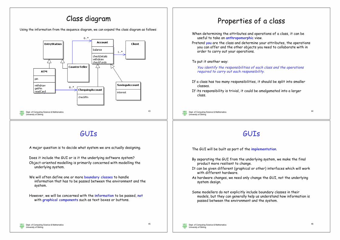
Class diagramUsing the information from the sequence diagram, we can expand the class diagram as follows:
Dept. of Computing Science & MathematicsUniversity of Stirling
44
Properties of a classWhen determining the attributes and operations of a class, it can be
useful to take an anthropomorphic view.Pretend you are the class and determine your attributes, the operations
you can offer and the other objects you need to collaborate with in order to carry out your operations.
To put it another way:You identify the responsibilities of each class and the operations required to carry out each responsibility.
If a class has too many responsibilities, it should be split into smaller classes.
If its responsibility is trivial, it could be amalgamated into a larger class.
Dept. of Computing Science & MathematicsUniversity of Stirling
45
GUIs
A major question is to decide what system we are actually designing.
Does it include the GUI or is it the underlying software system?Object-oriented modelling is primarily concerned with modelling the
underlying system.
We will often define one or more boundary classes to handle information that has to be passed between the environment and the system.
However, we will be concerned with the information to be passed, notwith graphical components such as text boxes or buttons.
Dept. of Computing Science & MathematicsUniversity of Stirling
46
GUIs
The GUI will be built as part of the implementation.
By separating the GUI from the underlying system, we make the final product more resilient to change.
It can be given different (graphical or other) interfaces which will work with different hardware.
As hardware changes, we need only change the GUI, not the underlying system design.
Some modellers do not explicitly include boundary classes in their models, but they can generally help us understand how information is passed between the environment and the system.
Dept. of Computing Science & MathematicsUniversity of Stirling
47
CRC CardsAnother way to help determine the properties of classes – a
brainstorming-like approach - is to use CRC cards, where CRC stands for Class, Responsibilities and Collaborations.
On each card, you write:• the name of the class,• the responsibilities of the class, i.e. a brief description of the
purpose of the class,• the collaborators of the class, i.e. the other classes that are needed
for this class to carry out its responsibilities.
A class will have an association with each of its collaborators.
CRC cards can be used to collect together information from the different sequence diagrams.
Dept. of Computing Science & MathematicsUniversity of Stirling
50
Case studies: OutlineI. Automated Banking System
Requirements Engineering: OO and incremental software development
1. case study: withdraw moneya. use casesb. identifying class/object (class diagram) c. interaction diagrams: sequence diagramsd. GUIs & CRC cards
2. case study: depositing moneya. sequence diagram (class diagram)b. communication diagram
Analysis and Design
Pre- post- conditions, design by contract
II. LibraryIII. Noughts and Crosses
Dept. of Computing Science & MathematicsUniversity of Stirling
51
Let us now consider another use case:
deposit cash with counter teller
A customer gives cash to a counter teller.
The counter teller enters the amount and the account number.
The system updates the account and issues a receipt.
Depositing cash
Dept. of Computing Science & MathematicsUniversity of Stirling
52
Depositing cash
The sequence diagram is:
If a use case is very simple, we do not have to create a sequence diagram. Could be argued that is the case here; depends on your level of experience.
Note the use of anAccount where Account is an abstract class.What we are modelling is that anAccount represents an instance of any of the subclasses of Account.
Dept. of Computing Science & MathematicsUniversity of Stirling
53
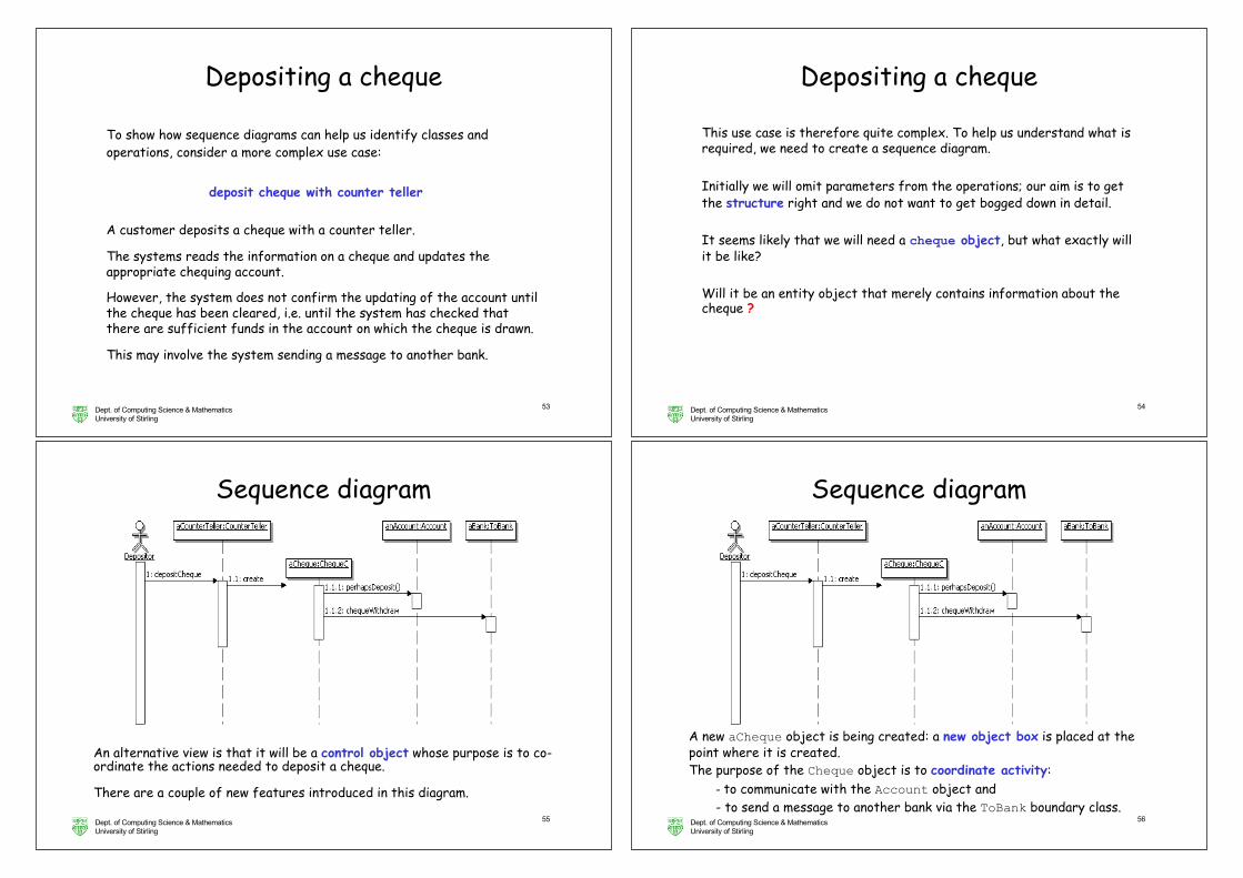
Depositing a cheque
To show how sequence diagrams can help us identify classes and operations, consider a more complex use case:
deposit cheque with counter teller A customer deposits a cheque with a counter teller.
The systems reads the information on a cheque and updates the appropriate chequing account.
However, the system does not confirm the updating of the account until the cheque has been cleared, i.e. until the system has checked that there are sufficient funds in the account on which the cheque is drawn.
This may involve the system sending a message to another bank.
Dept. of Computing Science & MathematicsUniversity of Stirling
54
Depositing a cheque
This use case is therefore quite complex. To help us understand what is required, we need to create a sequence diagram.
Initially we will omit parameters from the operations; our aim is to get the structure right and we do not want to get bogged down in detail.
It seems likely that we will need a cheque object, but what exactly will it be like?
Will it be an entity object that merely contains information about the cheque ?
Dept. of Computing Science & MathematicsUniversity of Stirling
55
Sequence diagram
An alternative view is that it will be a control object whose purpose is to co-ordinate the actions needed to deposit a cheque.
There are a couple of new features introduced in this diagram.
Dept. of Computing Science & MathematicsUniversity of Stirling
56
Sequence diagram
A new aCheque object is being created: a new object box is placed at the point where it is created.The purpose of the Cheque object is to coordinate activity:
- to communicate with the Account object and - to send a message to another bank via the ToBank boundary class.
Dept. of Computing Science & MathematicsUniversity of Stirling
57
Sequence diagram
Note that in creating this use case and associated sequence diagram, we have identified new classes:
the control class ChequeC and the boundary class ToBank
through which we can check that the other account has sufficient funds.We also identify operations such as
perhapsDeposit and confirmDeposit
and note that Account will need to have an extra attribute to hold the amount deposited by cheques, but which have yet to be confirmed. (Although we can only write cheques drawn on a chequing account, we can pay cheques into any kind of account.)
Dept. of Computing Science & MathematicsUniversity of Stirling
58
Sequence diagram
We also identify another use case:
check funds for issued cheque
Our bank must be able to deal with the case where another bank checks if one of our accounts has sufficient funds and if so we debit the account.
Dealing with the new use case may lead to the discovery of further classes.
It will also lead to another sequence diagram where information is sent from another bank.
Dept. of Computing Science & MathematicsUniversity of Stirling
59
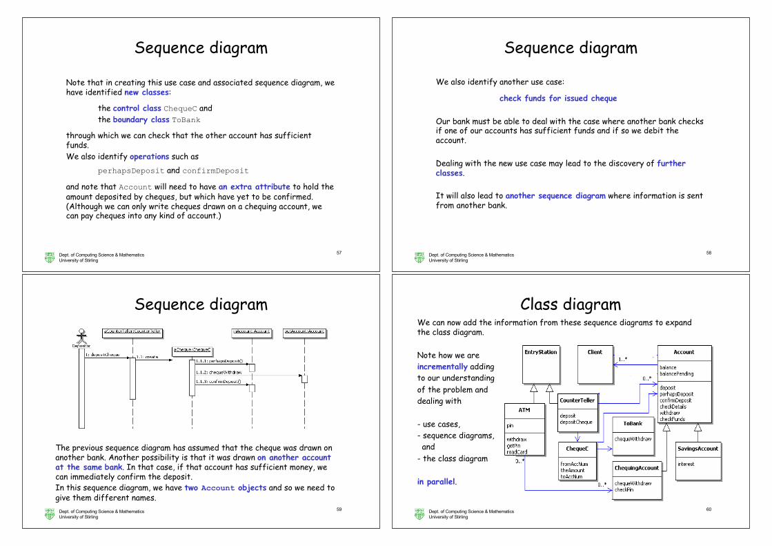
The previous sequence diagram has assumed that the cheque was drawn on another bank. Another possibility is that it was drawn on another account at the same bank. In that case, if that account has sufficient money, we can immediately confirm the deposit.In this sequence diagram, we have two Account objects and so we need to give them different names.
Sequence diagram
Dept. of Computing Science & MathematicsUniversity of Stirling
60
We can now add the information from these sequence diagrams to expand the class diagram.
Note how we are incrementally adding to our understanding of the problem and dealing with
- use cases, - sequence diagrams, and
- the class diagram
in parallel.
Class diagram
Dept. of Computing Science & MathematicsUniversity of Stirling
61
Operations
Many authors do not show attributes and operations at an early stage in the development of the class diagram.
In disagreement with that approach, other authors feel that one only really understands what a class does, when its main attributes and operations have been identified .
The list does not have to be complete; we can always add more as our knowledge increases.
Remember: Together allows you to set the level of details you want to be visible about operations at any stage.
Dept. of Computing Science & MathematicsUniversity of Stirling
62
As an alternative to sequence diagrams, we can use communication diagrams
(previously known as collaboration diagrams).
The objects that interact to perform some task, together with the links between them, are known as a collaboration.
Remember that a class diagram contains classes. A communication diagram is like part of a class diagram in which we represent objects rather than classes.
Communication diagrams show how instances of some of the classes in a class diagram collaborate with each other to carry out some task.
Tools enable sequence and communication diagrams to be converted from one to the other.
Communication diagrams
Dept. of Computing Science & MathematicsUniversity of Stirling
63
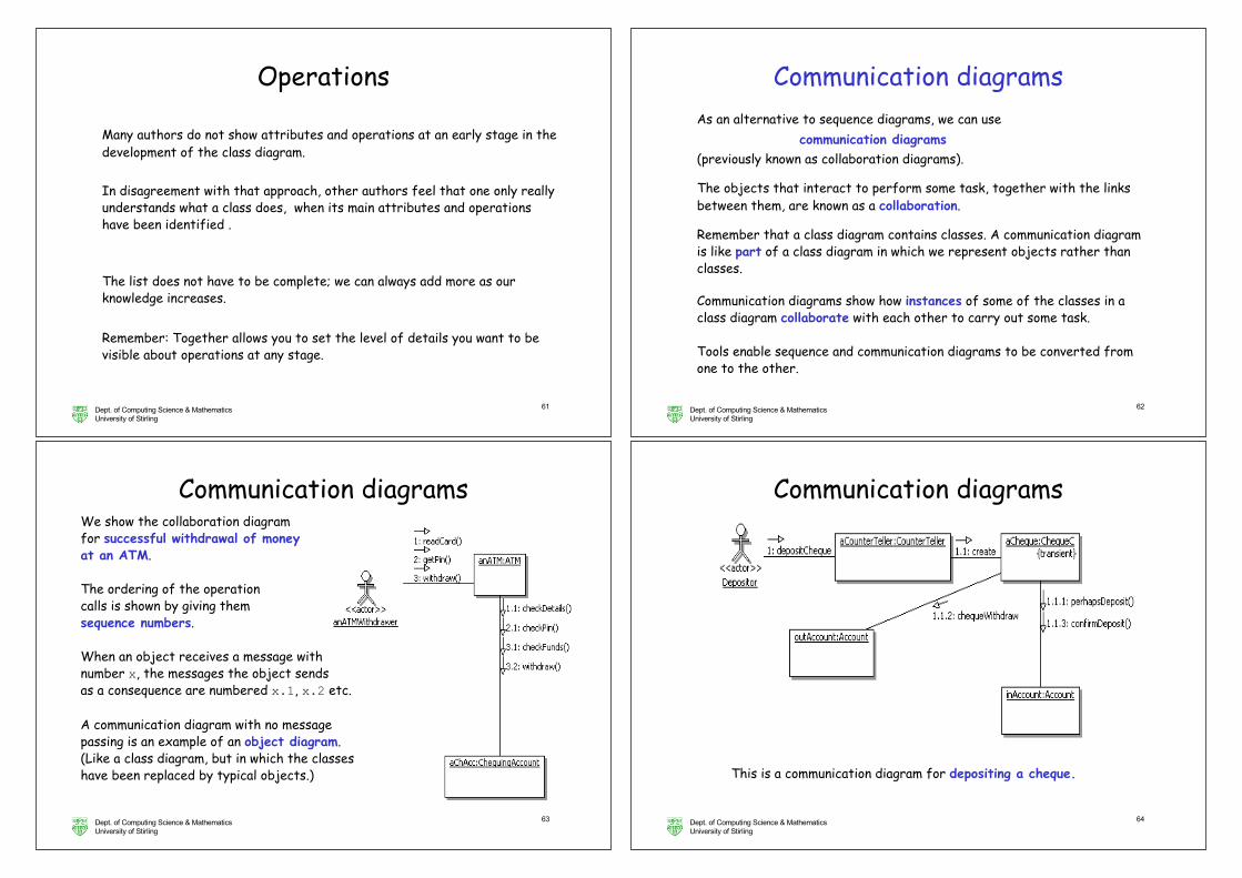
We show the collaboration diagram for successful withdrawal of money at an ATM.
The ordering of the operation calls is shown by giving them sequence numbers.
When an object receives a message with number x, the messages the object sends as a consequence are numbered x.1, x.2 etc.
A communication diagram with no message passing is an example of an object diagram. (Like a class diagram, but in which the classes have been replaced by typical objects.)
Communication diagrams
Dept. of Computing Science & MathematicsUniversity of Stirling
64
This is a communication diagram for depositing a cheque.
Communication diagrams
Dept. of Computing Science & MathematicsUniversity of Stirling
65
Case studies: OutlineI. Automated Banking System
Requirements Engineering: OO and incremental software development
1. case study: withdraw moneya. use casesb. identifying class/object (class diagram) c. interaction diagrams: sequence diagramsd. GUIs & CRC cards
2. case study: depositing moneya. sequence diagram (class diagram)b. communication diagram
Analysis and Design
Pre- post- conditions, design by contract
II. LibraryIII. Noughts and Crosses
Dept. of Computing Science & MathematicsUniversity of Stirling
66
UML models are used in different phases of software development.
Remember that in the requirements analysis phase our aim is to understand the problem and we do that by determining the behaviour that the actors want the system to provide.
As we move to more detailed analysis, and then design, our view of actorsand use cases can change.
From analysis to design models
Dept. of Computing Science & MathematicsUniversity of Stirling
67
From analysis to design models
Let us look at this through an example.
We identified a Depositor as an actor. The Depositor interacted with a Counter Teller.
In our initial analysis model, we are not concerned with computers and so we can regard a human Counter Teller as part of the Bank system with which the Depositor interacts.
As we go into more detail, we need to determine the boundary between the eventual system that we are to create and its environment.
Dept. of Computing Science & MathematicsUniversity of Stirling
68
More detailed analysis shows that Depositor interacts with a bank employee (a human Counter Teller) who interacts with a Counter Teller machine.
To help understand the problem, we can model the interaction between Depositor and a human Counter Teller, but we must realise that this interaction is between entities in the environment and is not part of the system that we are to design and implement.
This also means that some of our actors do not directly interact with the computer system, but interact with other actors.
From analysis to design models
Dept. of Computing Science & MathematicsUniversity of Stirling
69
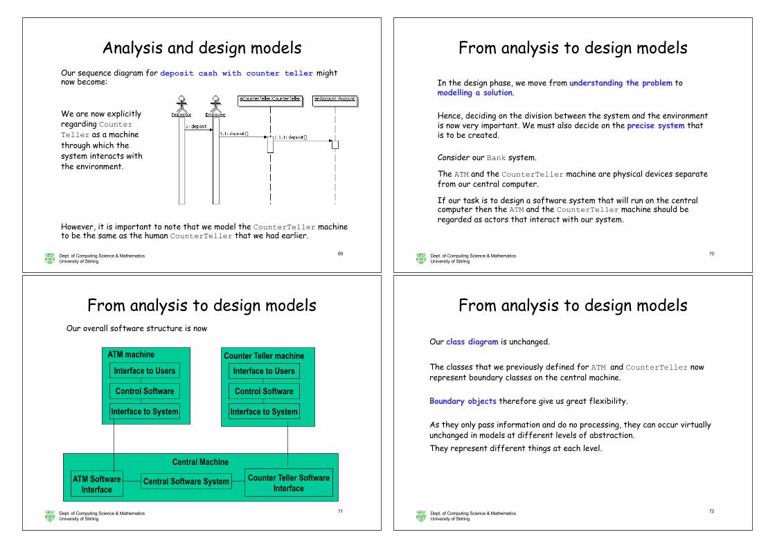
Our sequence diagram for deposit cash with counter teller might now become:
We are now explicitly regarding Counter Teller as a machine through which the system interacts with the environment.
However, it is important to note that we model the CounterTeller machine to be the same as the human CounterTeller that we had earlier.
Analysis and design models
Dept. of Computing Science & MathematicsUniversity of Stirling
70
From analysis to design models
In the design phase, we move from understanding the problem to modelling a solution.
Hence, deciding on the division between the system and the environment is now very important. We must also decide on the precise system that is to be created.
Consider our Bank system.
The ATM and the CounterTeller machine are physical devices separate from our central computer.
If our task is to design a software system that will run on the central computer then the ATM and the CounterTeller machine should be regarded as actors that interact with our system.
Dept. of Computing Science & MathematicsUniversity of Stirling
71
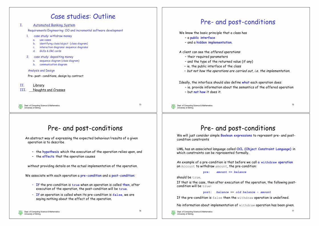
Our overall software structure is now
ATM machine
Control Software
Interface to Users
Interface to System
Counter Teller machine
Control Software
Interface to Users
Interface to System
Central Machine
ATM SoftwareInterface
Central Software System Counter Teller SoftwareInterface
From analysis to design models
Dept. of Computing Science & MathematicsUniversity of Stirling
72
From analysis to design models
Our class diagram is unchanged.
The classes that we previously defined for ATM and CounterTeller now represent boundary classes on the central machine.
Boundary objects therefore give us great flexibility.
As they only pass information and do no processing, they can occur virtually unchanged in models at different levels of abstraction.They represent different things at each level.
Dept. of Computing Science & MathematicsUniversity of Stirling
73
Case studies: OutlineI. Automated Banking System
Requirements Engineering: OO and incremental software development
1. case study: withdraw moneya. use casesb. identifying class/object (class diagram) c. interaction diagrams: sequence diagramsd. GUIs & CRC cards
2. case study: depositing moneya. sequence diagram (class diagram)b. communication diagram
Analysis and Design
Pre- post- conditions, design by contract
II. LibraryIII. Noughts and Crosses
Dept. of Computing Science & MathematicsUniversity of Stirling
75
We know the basic principle that a class has – a public interface– and a hidden implementation.
A client can see the offered operations:– their required parameters – and the type of the returned value (if any)– ie. the public interface of the class– but not how the operations are carried out, i.e. the implementation.
Ideally, the interface should also define what each operation does:– ie. provide information about the semantics of the offered operation– but not how it does it.
Pre- and post-conditions
Dept. of Computing Science & MathematicsUniversity of Stirling
76
An abstract way of expressing the expected behaviour/results of a given operation is to describe
– the hypothesis which the execution of the operation relies upon, and– the effects that the operation causes
without providing details on the actual implementation of the operation.
We associate with each operation a pre-condition and a post-condition:
– If the pre-condition is true when an operation is called then, after execution of the operation, the post-condition will be true.
– If an operation is called when its pre-condition is false, we are saying nothing about the effect of the operation.
Pre- and post-conditions
Dept. of Computing Science & MathematicsUniversity of Stirling
77
We will just consider simple Boolean expressions to represent pre- and post-condition constraints
UML has an associated language called OCL (Object Constraint Language) in which constraints can be represented formally.
An example of a pre-condition is that before we call a withdraw operationon Account to withdraw amount, the pre-condition:
pre: amount <= balance
should be true. If that is the case, then after execution of the operation, the following post-condition will be true:
post: balance == old balance - amount
If the pre-condition is false then the withdraw operation is undefined.
No information about implementation of withdraw operation has been given.
Pre- and post-conditions
Dept. of Computing Science & MathematicsUniversity of Stirling
78
As well as pre- and post-conditions, we can have class invariants.
A class invariant is a property that must hold throughout the life line of (an object of) a class – by design
The property must be true when the class is instantiated
If the property is true before an operation is called then it must be trueafter the operation is called
– During the call the property might not be true, but must become true by the end of the operation.
Therefore the property will be true whenever no operation is in progress– (If there is no interference)
Pre- and post-conditions and class invariants are very useful at giving extra information to our models
– mainly clarification of design decisions and– constraints on admissible behaviour.
Class invariant
Dept. of Computing Science & MathematicsUniversity of Stirling
79
A possible class invariant on Account is:balance >= 0
that is throughout the life of an Account object, the balance is never allowed to go negative. Check: withdraw OK? (Yes) depositCash OK? (Pre-cond required)
It may be the case that a class invariant will become false during the execution of an operation, but the operation must ensure that it becomes true again before the operation terminates.
For instance, a possible (may be not ideal) implementation of the withdrawoperation could:
– subtract the requested amount,– only subsequently check that the balance is not negative– and, if it is, cancel the operation and restore the original balance. – This would fulfill the class invariant.
Class invariant
Dept. of Computing Science & MathematicsUniversity of Stirling
80
Class invariantFor them to be really useful, of course, they need to be checked to ensure that they are satisfied.
That is not yet part of UML tools and is not part of most programming languages.
The object-oriented programming language Eiffel has assertions that allow these conditions to be checked.
The question of course remains:
what do you do if an assertion fails?
Dept. of Computing Science & MathematicsUniversity of Stirling
81
Inheritance and conditionsRemember that a main principle of the object-oriented approach is
An object of a subclass can be used
anywhere
an object of its superclass is expected.
That means that the subclass must be able to fulfill the contract entered into by the superclass
– The form of the contract is: If a client calls an operation when its pre-condition is true, then it guarantees to satisfy its post-condition
The catchy (if rather trite) slogan for a subclass is:
Demand no more; promise no less.
Dept. of Computing Science & MathematicsUniversity of Stirling
82
Inheritance and conditionsDemand no more means that an operation offered by a subclass must be willing to accept all parameter values that the superclass would allow.
can you imagine this in terms of preconditions ?
The pre-condition in the subclass must be no stronger than the pre-condition in the superclass, e.g.
pre: 10 <= amount <= balance
for a withdraw operation of a subclass of Account is not ok, as it restricts the range of values for which the operation is defined.
This pre-condition guarantees that the post-condition of the withdraw operation of the subclass, a SavingAccount say, holds only when the operation is called with an ammount bigger than 10, a constraint what was not present in the superclass.
Dept. of Computing Science & MathematicsUniversity of Stirling
83
Inheritance and conditionsPromise no less means that any assumption about the result that was valid when the superclass implementation was being used must still be valid when the subclass implementation is used.
can you imagine this in terms of preconditions ?
The post-condition in the subclass must be at least as strong as the post-condition in the superclass, e.g.
post: balance >= old balance - amount
for a withdraw operations of a subclass of Account is not ok, as it expands the range of possible values in the account after the execution of the operation.
Note that pre- and post-conditions give us a way of specifying that a subclass offers the same behaviour as the superclass, i.e. that we have behavioural inheritance.
Dept. of Computing Science & MathematicsUniversity of Stirling
84
Design by contract(what do you do if an assertion fails?)
Pre- and post-conditions can be used to support the idea of design by contract
Consider the situation where a withdraw method is called:– Whose responsibility is it that the account has sufficient funds?– Should the method have to check that it has been called correctly?
Design by contract is an approach where it is considered an error to calla method when its pre-condition is false:
– It is then the responsibility of the client to check that the pre-condition is true
– The operation need not check
Dept. of Computing Science & MathematicsUniversity of Stirling
85
Design by contract
To summarise, an object makes a contract with its clients that guarantees that when one of its operations is called when the pre-condition is true then, after execution of the operation, the post-condition will be true.
If an operation is called when its pre-condition is false, the object guarantees nothing about the effect of the operation.
The idea is that one side will make the check, not neither or both.
The opposite is defensive programming:– Each operation's implementation explicitly checks that its pre-
condition is satisfied– BIG DEBATE ONGOING !
Dept. of Computing Science & MathematicsUniversity of Stirling
86
Design by contract: caveatsYou might not be happy with the use of pre- and post-conditions in
design by contract:– We are effectively saying that a class definition can ignore
difficult situations– (E.g. Integer.parseInt does not assume its parameter is digits
-- defensive programming ! ! ! )
It is of most use when you specify or design a system as a set of collaborating classes:
– You are then making a decision within the collaboration about which class is responsible for each check
But there are then dangers if one of the classes is used in a different environment in which the designer does not fully realise
– the implication of the pre-condition and – that the client must perform the necessary checks.
Dept. of Computing Science & MathematicsUniversity of Stirling
87
Case studies: OutlineI. Automated Banking System
Requirements Engineering: OO and incremental software development
1. case study: withdraw moneya. use casesb. identifying class/object (class diagram) c. interaction diagrams: sequence diagramsd. GUIs & CRC cards
2. case study: depositing moneya. sequence diagram (class diagram)b. communication diagram
Analysis and Design
Pre- post- conditions, design by contract
II. LibraryIII. Noughts and Crosses


![Power Pint Withdraw Gold[1]](https://img.pdfslide.us/doc/110x75/577c7bd41a28abe05498811a/power-pint-withdraw-gold1.jpg)