Embed Size (px)
Citation preview
A R C H I V E S
o f
F O U N D R Y E N G I N E E R I N G
Published quarterly as the organ of the Foundry Commission of the Polish Academy of Sciences
ISSN (1897-3310) Volume 10
Issue Special1/2010 365-370
71/1
Case studies of steel structure failures
P. Bernasovský
Welding Research Institute – Industrial Institute of SR, Račianska 71, 832 59 Bratislava, Slovakia
Received 05.03.2010; accepted in revised form 23.03.2010
Abstract The contribution deals with some case studies of steel structure failures, which happened in Slovakia a few years ago. Features of cracking are illustrated on real cases of breakdowns in the transmission gas pipelines, at the cement works and in the petrochemical indus-try. All failures were caused by an incorrect technical approach. Possible remedial measures are proposed. Key words: Case studies; Liquid metal embrittlement; Intercrystalline stress corrosion cracking; Thermal fatigue; Cold plastic straining; Eddy current NDT
1. Liquid metal embrittlement 1.1 First international gas pipeline [1]
This case occurred on the 1st international gas pipeline which was built in 1965. This line, made of an old Russian steel 15 G2S (type L290N) low alloyed with Si (see Table 1) is the most problematic one at present. In this line low ductility and toughness of steel have met together which poor workmanship and defective corrosion protection of pipeline. Table 1 – Chemical composition [wt %] and mechanical properties of the 15 G2S steel
C Mn Si P S Cr Ni Cu Ti
0,14-0,15
1,37-1,45
1,07-1,08
0,014 0,029 0,06 0,05 0,08 0,032
Re [MPa] Rm [MPa] A5 [%] ChV FATT (50J.cm-2)
Upper shelf
387 – 404 591 - 612 22 - 27 + 140 C 55 J.cm-2
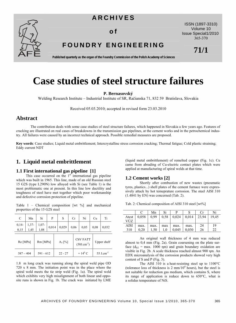
1.8 m long crack was running along the spiral weld pipe OD 720 x 8 mm. The initiation point was in the place where the spiral weld meets the tie strip weld (Fig. 1a). The spiral weld which exhibits very high misalignment of both linear and oppo-site runs is shown in Fig. 1b. The crack was initiated by LME
(liquid metal embrittlement) of remelted copper (Fig. 1c). Cu came from abrading of Cu-electric contact plates which were applied at manufacturing of spiral welds at that time. 1.2 Cement works [2] Shortly after combustion of new wastes (pneumatic tyres, plastics...) shell plates of the cement furnace were expres-sively attack by hot temeprature corrosion. The steel AISI 310 (1.4841 by EN) was concerned (Tab. 2). Tab. 2: Chemical composition of AISI 310 steel [wt%]
C Mn Si P S Cr Ni Atest VÚZ
0,058 0,99 0,58 0,024 0,014 23,94 19,45
AISI 310
max. 0,20
max. 1,50
max 1,0
max. 0,045
max. 0,030
24 26
19 22
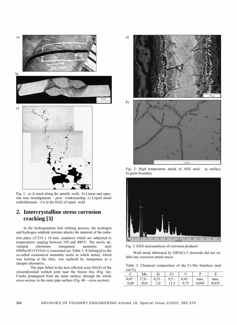
An original wall thickness of 4 mm was reduced almost to 0,4 mm (Fig. 2a). Grain coarsening on the plate sur-face (dST = max. 1000 ηm) and grain boundary oxidation are visible in Fig. 2b. A scale thickness reached almost 900 ηm. An EDX microanalysis of the corrosion products showed very high content of S and P (Fig. 3). The AISI 310 is a heat-resisting steel up to 1100°C (tolerance loss of thickness is 2 mm/104 hours), but the steel is not suitable for reduction gas medium, which contains S, where its range of application is reduce down to 650°C, what is a solidus temperature of NiS.
ARCHIVES OF FOUNDRY ENGINEERING Vo lume 10 , Spec ia l I ssue 1 /2010 , 365-370
365
a)
b)
c)
Fig. 1: a) A crack along the spirally weld, b) Linear and oppo-site runs misalignment – poor workmanship, c) Liquid metal embrittlement – Cu in the HAZ of repair weld
2. Intercrystalline stress corrosion cracking [3]
In the hydrogenation fuel refining process, the hydrogen and hydrogen sulphide mixture attacks the material of the radia-tion pipes (∅219 x 14 mm, seamless) which are subjected to temperatures ranging between 350 and 400°C. The newly de-veloped chromium manganese austenitic steel (08Mn18Cr11V0,6) is concerned see Table 3. It belonged to the so-called economical austenitic steels in which nickel, which was lacking at the time, was replaced by manganese as a cheaper alternative.
The pipe failed in the heat affected zone (HAZ) of the circumferential welded joint near the fusion line (Fig. 4a). Cracks propagated from the inner surface, through the whole cross section, to the outer pipe surface (Fig. 4b – cross section).
a)
b)
Fig. 2: High temperature attack of AISI steel: a) surface, b) grain boundary
Fig. 3: EDX microanalysis of corrosion products
Weld metal fabricated by ERNiCr-3 electrode did not ex-hibit any corrosion attack traces. Table 3. Chemical composition of the Cr-Mn Stainless steel (wt.%)
C Mn Si Cr V P S 0,05 – 0,08
17,0 – 20,0
0,25 – 1,0
9,5 – 11,5
0,45 – 0,75
max. 0,045
max. 0,035
ARCHIVES OF FOUNDRY ENGINEERING Vo lume 10 , Spec ia l I ssue 1 /2010 , 365-370
366
a)
b)
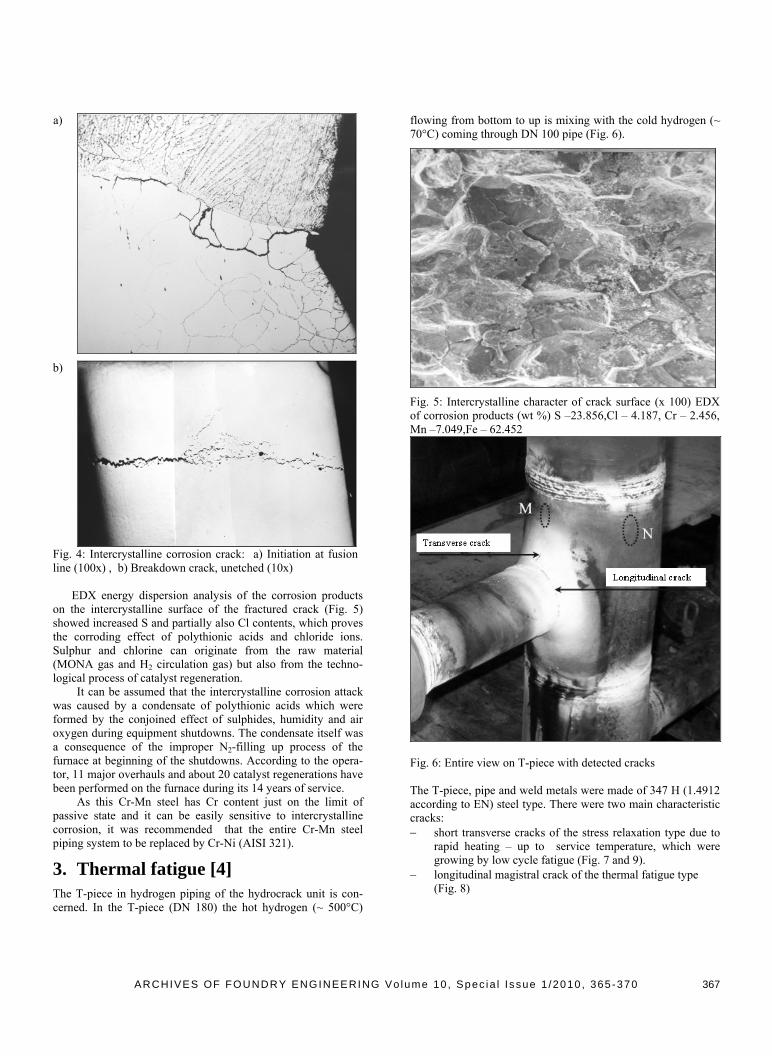
Fig. 4: Intercrystalline corrosion crack: a) Initiation at fusion line (100x) , b) Breakdown crack, unetched (10x)
EDX energy dispersion analysis of the corrosion products on the intercrystalline surface of the fractured crack (Fig. 5) showed increased S and partially also Cl contents, which proves the corroding effect of polythionic acids and chloride ions. Sulphur and chlorine can originate from the raw material (MONA gas and H2 circulation gas) but also from the techno-logical process of catalyst regeneration. It can be assumed that the intercrystalline corrosion attack was caused by a condensate of polythionic acids which were formed by the conjoined effect of sulphides, humidity and air oxygen during equipment shutdowns. The condensate itself was a consequence of the improper N2-filling up process of the furnace at beginning of the shutdowns. According to the opera-tor, 11 major overhauls and about 20 catalyst regenerations have been performed on the furnace during its 14 years of service. As this Cr-Mn steel has Cr content just on the limit of passive state and it can be easily sensitive to intercrystalline corrosion, it was recommended that the entire Cr-Mn steel piping system to be replaced by Cr-Ni (AISI 321).
3. Thermal fatigue [4]
The T-piece in hydrogen piping of the hydrocrack unit is con-cerned. In the T-piece (DN 180) the hot hydrogen (~ 500°C)
flowing from bottom to up is mixing with the cold hydrogen (~ 70°C) coming through DN 100 pipe (Fig. 6).
Fig. 5: Intercrystalline character of crack surface (x 100) EDX of corrosion products (wt %) S –23.856,Cl – 4.187, Cr – 2.456, Mn –7.049,Fe – 62.452
Fig. 6: Entire view on T-piece with detected cracks The T-piece, pipe and weld metals were made of 347 H (1.4912 according to EN) steel type. There were two main characteristic cracks: − short transverse cracks of the stress relaxation type due to
rapid heating – up to service temperature, which were growing by low cycle fatigue (Fig. 7 and 9).
− longitudinal magistral crack of the thermal fatigue type (Fig. 8)
ARCHIVES OF FOUNDRY ENGINEERING Vo lume 10 , Spec ia l I ssue 1 /2010 , 365-370
367
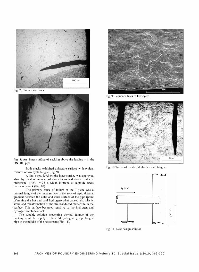
Fig. 7: Transverse crack
Fig. 8: An inner surface of necking above the leading – in the DN 100 pipe
Both cracks exhibited a fracture surface with typical features of low cycle fatigue (Fig. 9).
A high stress level on the inner surface was approved also by local occurence of strain twins and strain induced martensite (HV0,5 = 331), which is prone to sulphide stress corrosion attack (Fig. 10). The primary cause of failure of the T-piece was a thermal fatigue of the inner surface in the zone of rapid thermal gradient between the outer and inner surface of the pipe (point of mixing the hot and cold hydrogen) what caused also plastic strain and transformation of the strain-induced martensite in the surface. This surface becomes sensitive to the hydrogen and hydrogen sulphide attack. The suitable solution preventing thermal fatigue of the necking would be supply of the cold hydrogen by a prolonged pipe to the middle of the hot stream (Fig. 11).
Fig. 9: Sequence lines of low cycle
Fig. 10:Traces of local cold plastic strain fatigue
Fig. 11: New design solution
ARCHIVES OF FOUNDRY ENGINEERING Vo lume 10 , Spec ia l I ssue 1 /2010 , 365-370
368
4. Cold plastic straining 4.1 Cold strain impression of weld rein-forcement [5]
This case appeared at construction (laying) of 4th transmis-sion line OD 1420 x 18.6 mm made of X-70 (L 485 MB) steel grade spirally welded pipes. During bending of pipes on site a few pipes cracked along the spiral welds. The cracks in length up to 1 m always appeared in the same distance from the pipe end (Fig. 12). The crack occurrence corresponded with appearance of a cold impression on the outer spiral weld reinforcement (Fig. 13). It was found that such impression was formed due to incorrectly installed supporting steel rollers in the furnace used for pipe insulation. In this furnace the pipes are flame heated prior to PE insulation up to 300 0C, whereas they rotate (about 70 revolutions) on the rollers. In certain period of manufacture some pairs of rollers were taken out for the repair, and therefore the pipe weight (about 12 tons) was supported by the remaining pair (in 11.5 m distance). Since all inspection of pipes was performed prior to pipe insulation such impression could not be detected.
Fig. 12 – Sketch of the fractured pipe
Fig. 13 – Fracture of the spiral weld due to outer impresion This finding resulted in repeated ultrasonic inspection of all bent pipes manufactured in that period (about 300 pipes). The prob-lem was, that the concerned pipes were already distributed in
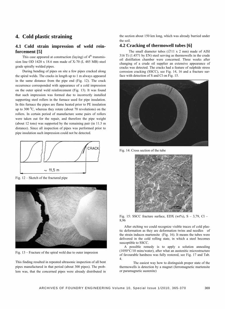
the section about 150 km long, which was already burried under the soil. 4.2 Cracking of thermowell tubes [6] The small diameter tubes (∅11 x 2 mm) made of AISI 316 Ti (1.4571 by EN) steel serving as thermowells in the crude oil distillation chamber were concerned. Three weeks after changing of a crude oil supplier an extensive appearance of cracks was detected. The cracks had a feature of sulphide stress corrosion cracking (SSCC), see Fig. 14, 16 and a fracture sur-face with detection of S and Cl on Fig. 15.
Fig. 14: Cross section of the tube
Fig. 15: SSCC fracture surface, EDX (wt%), S – 3,79, Cl – 8,96
After etching we could recognize visible traces of cold plas-tic deformation as they are deformation twins and needles of the strain induces martensite (Fig. 16). It means the tubes were delivered in the cold rolling state, in which a steel becomes susceptible to SSCC. A possible remedy is to apply a solution annealing (1050°C/10 mins/water), after what an austenitic microstructure of favourable hardness was fully restored, see Fig. 17 and Tab. 4. The easiest way how to distinguish proper state of the thermowells is detection by a magnet (ferromagnetic martensite or paramagnetic austenite)
ARCHIVES OF FOUNDRY ENGINEERING Vo lume 10 , Spec ia l I ssue 1 /2010 , 365-370
369
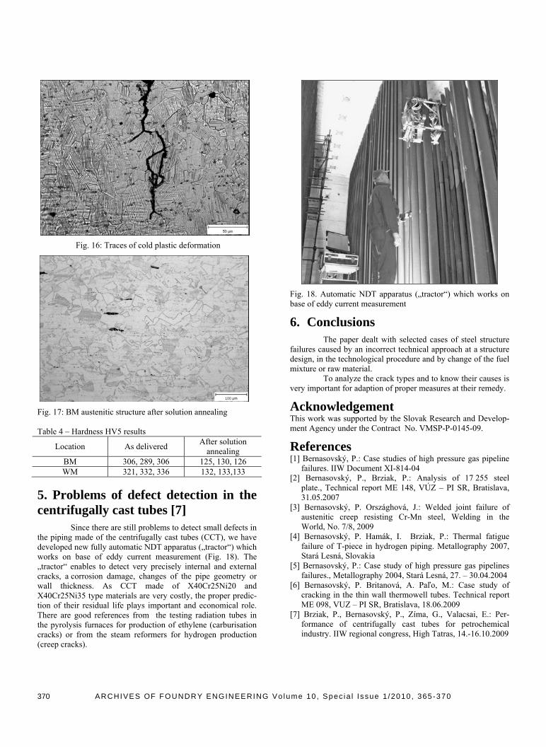
Fig. 16: Traces of cold plastic deformation
Fig. 17: BM austenitic structure after solution annealing Table 4 – Hardness HV5 results
Location As delivered After solution annealing
BM 306, 289, 306 125, 130, 126 WM 321, 332, 336 132, 133,133
5. Problems of defect detection in the centrifugally cast tubes [7]
Since there are still problems to detect small defects in the piping made of the centrifugally cast tubes (CCT), we have developed new fully automatic NDT apparatus („tractor“) which works on base of eddy current measurement (Fig. 18). The „tractor“ enables to detect very precisely internal and external cracks, a corrosion damage, changes of the pipe geometry or wall thickness. As CCT made of X40Cr25Ni20 and X40Cr25Ni35 type materials are very costly, the proper predic-tion of their residual life plays important and economical role. There are good references from the testing radiation tubes in the pyrolysis furnaces for production of ethylene (carburisation cracks) or from the steam reformers for hydrogen production (creep cracks).
Fig. 18. Automatic NDT apparatus („tractor“) which works on base of eddy current measurement
6. Conclusions
The paper dealt with selected cases of steel structure failures caused by an incorrect technical approach at a structure design, in the technological procedure and by change of the fuel mixture or raw material. To analyze the crack types and to know their causes is very important for adaption of proper measures at their remedy.
Acknowledgement This work was supported by the Slovak Research and Develop-ment Agency under the Contract No. VMSP-P-0145-09.
References [1] Bernasovský, P.: Case studies of high pressure gas pipeline
failures. IIW Document XI-814-04 [2] Bernasovský, P., Brziak, P.: Analysis of 17 255 steel
plate., Technical report ME 148, VÚZ – PI SR, Bratislava, 31.05.2007
[3] Bernasovský, P. Országhová, J.: Welded joint failure of austenitic creep resisting Cr-Mn steel, Welding in the World, No. 7/8, 2009
[4] Bernasovský, P. Hamák, I. Brziak, P.: Thermal fatigue failure of T-piece in hydrogen piping. Metallography 2007, Stará Lesná, Slovakia
[5] Bernasovský, P.: Case study of high pressure gas pipelines failures., Metallography 2004, Stará Lesná, 27. – 30.04.2004
[6] Bernasovský, P. Britanová, A. Paľo, M.: Case study of cracking in the thin wall thermowell tubes. Technical report ME 098, VUZ – PI SR, Bratislava, 18.06.2009
[7] Brziak, P., Bernasovský, P., Zíma, G., Valacsai, E.: Per-formance of centrifugally cast tubes for petrochemical industry. IIW regional congress, High Tatras, 14.-16.10.2009
ARCHIVES OF FOUNDRY ENGINEERING Vo lume 10 , Spec ia l I ssue 1 /2010 , 365-370
370