Embed Size (px)
Citation preview
Case Studies of Cable Bolts Using Instrumented King Wires
Lewis A. Martin Spokane Research Laboratory, National Institute for Occupational Safety and Health, Spokane, WA
R. PakalnisUniversity of British Columbia, Vancouver, BC
Richard P. CurtinSpokane Research Laboratory, National Institute for Occupational Safety and Health, Spokane, WA
ABSTRACT
Instrumented cable bolts developed at the Spokane Research Laboratory of the National Institute forOccupational Safety and Health were used in conjunction with existing ground control to monitor rock massloads at various field sites (FMC Granger, Getchell, Meikle, SSX, K-2, and Stillwater). Axial and shear loadswere determined by strain gauges to levels of instrument accuracy of ±5 N or ±5 microstrain as these loads weretransferred to the instrumented cable bolts. These gauges were 12.5 mm long and embedded into aremanufactured king wire that replaced the conventional king wire. Cable bolt performance, quality of grout,and installation techniques were also assessed. By using instrumented cables, a mine operator can determineaxial load along the cable at predefined gauge locations. By monitoring load on and displacement of the rockmass, more effective ground support can be selected and installed, which will lead to safer working conditionsfor miners.
BACKGROUND
Until recently, external measurement devices such asthe tensmeg or resistance wire cable strain cell gauges(Hyett et al. 1997) were used to determine load oncable bolts. In 1996, the “stretch measurement toassess reinforcement tension” (SM.A.R.T) cable wasdeveloped and patented by researchers at QueensUniversity (Hyett et al. 1997). This system replacesthe king wire of a cable bolt with multipoint exten-someters (MPBX’s) enclosed in a tube to measurecable elongation, thereby enabling deformation andload to be determined (Bawden et al. 1998).
Researchers have previously expressed the view thatan internal gauge would be too expensive to use withcables as an instrument within mines. Another issueis that external gauges on cables may fail because ofwater seepage through the grout before the cablebegins to take on load (Goris et al. 1993). The use-fulness of a ground control instrument having gaugesmounted in the center of the cable or on the king wirewas shown by Signer (1990) in research on the use ofresin-grouted rebar bolts in coal mines.
Rock mass, grout quality, effective anchorage length,
and cable load can now be determined with cement-and epoxy-grouted cables. In 1998, researchers at theSpokane Research Laboratory (SRL) of the NationalInstitute for Occupational Safety and Health (NIOSH)developed an “Instrumented King Wire Cable Bolt”(patent 60/076,138). This instrument uses a differentapproach during the manufacturing process in whichthe king wire is molded from epoxy around a flat pieceof steel containing strain gauges.
CONCEPT
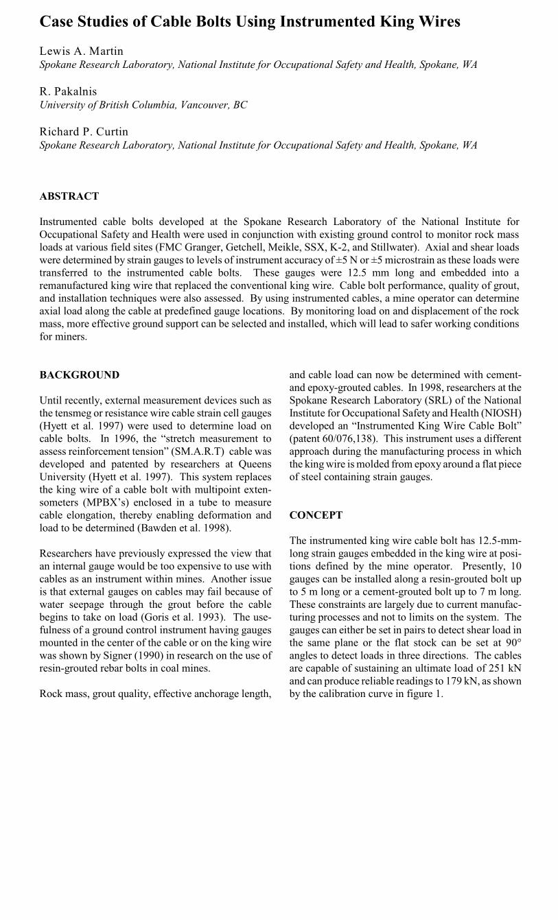
The instrumented king wire cable bolt has 12.5-mm-long strain gauges embedded in the king wire at posi-tions defined by the mine operator. Presently, 10gauges can be installed along a resin-grouted bolt upto 5 m long or a cement-grouted bolt up to 7 m long.These constraints are largely due to current manufac-turing processes and not to limits on the system. Thegauges can either be set in pairs to detect shear load inthe same plane or the flat stock can be set at 90°angles to detect loads in three directions. The cablesare capable of sustaining an ultimate load of 251 kNand can produce reliable readings to 179 kN, as shownby the calibration curve in figure 1.
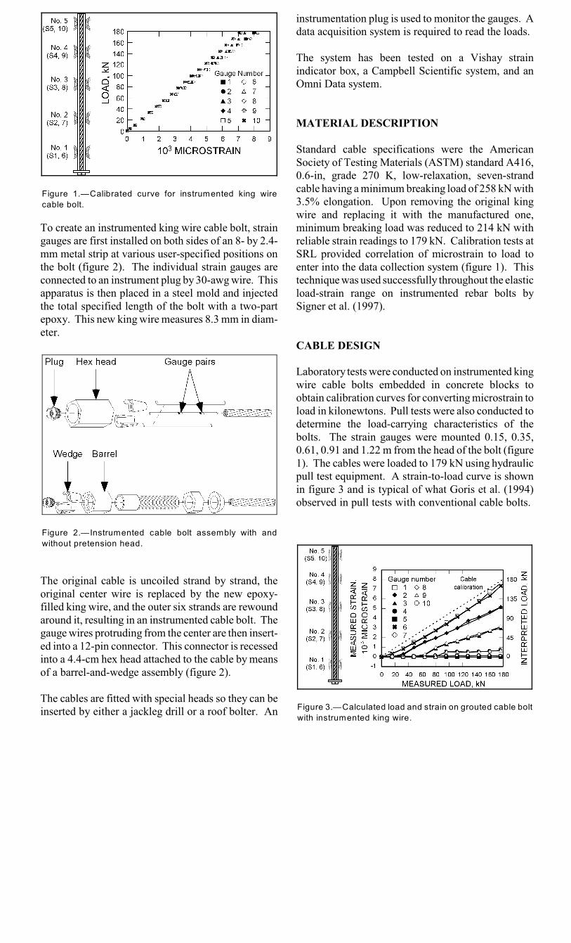
Figure 1.—Calibrated curve for instrumented king wire
cable bolt.
Figure 2.—Instrumented cable bolt assembly with and
without pretension head.
Figure 3.—Calculated load and strain on grouted cable bolt
with instrumented king wire.
To create an instrumented king wire cable bolt, straingauges are first installed on both sides of an 8- by 2.4-mm metal strip at various user-specified positions onthe bolt (figure 2). The individual strain gauges areconnected to an instrument plug by 30-awg wire. Thisapparatus is then placed in a steel mold and injectedthe total specified length of the bolt with a two-partepoxy. This new king wire measures 8.3 mm in diam-eter.
The original cable is uncoiled strand by strand, theoriginal center wire is replaced by the new epoxy-filled king wire, and the outer six strands are rewoundaround it, resulting in an instrumented cable bolt. Thegauge wires protruding from the center are then insert-ed into a 12-pin connector. This connector is recessedinto a 4.4-cm hex head attached to the cable by meansof a barrel-and-wedge assembly (figure 2).
The cables are fitted with special heads so they can beinserted by either a jackleg drill or a roof bolter. An
instrumentation plug is used to monitor the gauges. Adata acquisition system is required to read the loads.
The system has been tested on a Vishay strainindicator box, a Campbell Scientific system, and anOmni Data system.
MATERIAL DESCRIPTION
Standard cable specifications were the AmericanSociety of Testing Materials (ASTM) standard A416,0.6-in, grade 270 K, low-relaxation, seven-strandcable having a minimum breaking load of 258 kN with3.5% elongation. Upon removing the original kingwire and replacing it with the manufactured one,minimum breaking load was reduced to 214 kN withreliable strain readings to 179 kN. Calibration tests atSRL provided correlation of microstrain to load toenter into the data collection system (figure 1). Thistechnique was used successfully throughout the elasticload-strain range on instrumented rebar bolts bySigner et al. (1997).
CABLE DESIGN
Laboratory tests were conducted on instrumented kingwire cable bolts embedded in concrete blocks toobtain calibration curves for converting microstrain toload in kilonewtons. Pull tests were also conducted todetermine the load-carrying characteristics of thebolts. The strain gauges were mounted 0.15, 0.35,0.61, 0.91 and 1.22 m from the head of the bolt (figure1). The cables were loaded to 179 kN using hydraulicpull test equipment. A strain-to-load curve is shownin figure 3 and is typical of what Goris et al. (1994)observed in pull tests with conventional cable bolts.

Figure 4.—Instrument locations in trona mine.
Figure 5.—Bolt and sagmeter locations.
These tests aid in explaining how load on cable boltsis transferred from the cable to the grout and then intothe rock mass. A “shelling” effect is shown wherebythe grout-cable interface breaks down and the gaugebecomes unbonded as load is increased and is takenfully by the cable. Figure 3 shows results of the pulltests as a load profile along the cable length. Thecurve shows that a 128-kN (~12.8-tonne) pull load onthe collar of the cable resulted in measured strainloads of 123 kN along gauges 1 and 6 at a distance of0.15 m from the collar. Researchers interpreted thismeasure-ment (5 kN) as the amount of load the cablewas not sensing 0.15 m from the collar. At 1.22 mfrom the collar, the cable did not sense any load,which indicates critical bond length. Otherresearchers (e.g., Goris et al. 1994). have reportedcritical bond length to be approximately 1 m forstandard cable. This load capability enables anoperator to measure failure in real time as debondingof the grout-cable interface is initiated. In addition,the difference between cable load and applied loadindicates grout quality, which can be a better field testof the quality of cable bolt installations than field pulltests.
CASE STUDIES
Cable bolts with instrumented king wires were testedat six mines. The results of these tests are describedbelow. For simplification, the terms “cable bolts” willmean bolts in which the conventional king wire hasbeen replaced with the new remanufactured king wire.
Case Study 1: Trona (FMC Granger)
Cable bolts were installed in the roof of FMCGrangers’s trona mine, a room-and-pillar operation inWyoming, to measure roof loads in the intersection of350S and 12371E (figures 4 and 5). This location waschosen because of drill access ahead of the miningcycle and because loads would be induced in the cablebolts as ore was extracted toward the intersection.Mine personnel were interested in determining thepotential for instability in the back and the extent ofany unwedged blocks.
Ground support was installed after development andduring rehabilitation. Strain gauges were positionedalong rebar and cable bolts at depths that would ensurethat loads in the resin grout would be measured. Inaddition, a set of gauges was mounted at an ungroutedsection to measure dead weight loads
in the rock mass. Figure 6 shows the position of thestrain gauges with respect to the collar. The longestcable bolts were installed at the center of the intersec-tion because these bolts would receive the greatestloads, while shorter cable bolts were installed north ofthe intersection closer to the pillar front. Resin-grouted rebar bolts were placed in the south part of theintersection to measure loads where the density ofrebar bolts was highest. Sagmeter stations were set at
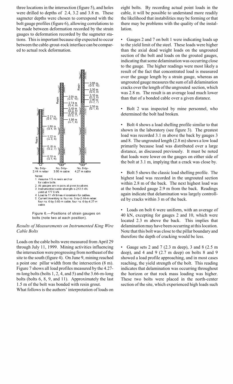
Figure 6.—Positions of strain gauges on
bolts (note two at each position).
three locations in the intersection (figure 5), and holeswere drilled to depths of 2.4, 3.2 and 3.8 m. Thesesagmeter depths were chosen to correspond with thebolt gauge profiles (figure 6), allowing correlations tobe made between deformation recorded by the straingauges to deformation recorded by the sagmeter sta-tions. This is important because slip expected to occurbetween the cable-grout-rock interface can be compar-ed to actual rock deformation.
Results of Measurements on Instrumented King WireCable Bolts
Loads on the cable bolts were measured from April 29through July 11, 1999. Mining activities influencingthe intersection were progressing from northeast of thesite to the south (figure 4). On June 9, mining reacheda point one pillar width from the intersection (8 m).Figure 7 shows all load profiles measured by the 4.27-m-long bolts (bolts 1, 2, 4, and 5) and the 3.66-m-longbolts (bolts 6, 8, 9, and 11). Approximately the last1.5 m of the bolt was bonded with resin grout.What follows is the authors’ interpretation of loads on
eight bolts. By recording actual point loads in thecable, it will be possible to understand more readilythe likelihood that instabilities may be forming or thatthere may be problems with the quality of the instal-lation.
• Gauges 2 and 7 on bolt 1 were indicating loads upto the yield limit of the steel. These loads were higherthan the axial dead weight loads on the ungroutedsection of the bolt and loads on the grouted gauges,indicating that some delamination was occurring closeto the gauge. The higher readings were most likely aresult of the fact that concentrated load is measuredover the gauge length by a strain gauge, whereas anungrouted gauge measures the sum of all delaminationcracks over the length of the ungrouted section, whichwas 2.8 m. The result is an average load much lowerthan that of a bonded cable over a given distance.
• Bolt 2 was inspected by mine personnel, whodetermined the bolt had broken.
• Bolt 4 shows a load shelling profile similar to thatshown in the laboratory (see figure 3). The greatestload was recorded 3.1 m above the back by gauges 3and 8. The ungrouted length (2.8 m) shows a low loadprimarily because load was distributed over a largedistance, as discussed previously. It must be notedthat loads were lower on the gauges on either side ofthe bolt at 3.1 m, implying that a crack was close by.
• Bolt 5 shows the classic load shelling profile. Thehighest load was recorded in the ungrouted sectionwithin 2.8 m of the back. The next highest load wasat the bonded gauge 2.9 m from the back. Readingsagain indicate that delamination was largely controll-ed by cracks within 3 m of the back.
• Loads on bolt 6 were uniform, with an average of40 kN, excepting for gauges 2 and 10, which werelocated 2.3 m above the back. This implies thatdelamination may have been occurring at this location.Note that this bolt was close to the pillar boundary andtherefore the depth of cracking would be less.
• Gauge sets 2 and 7 (2.3 m deep), 3 and 8 (2.5 mdeep), and 4 and 9 (2.7 m deep) on bolts 8 and 9showed a load profile approaching, and in most casesreaching, the yield strength of the bolt. This readingindicates that delamination was occurring throughoutthe horizon or that rock mass loading was higher.These two bolts were placed in the north-centersection of the site, which experienced high loads such

Figure 7.—Load profile versus time on 4.27-m-long bolts (1, 2, 4, and 5) and 3.66-m-long bolts (6, 8, 9, and 11).

Figure 8.—Displacement of back over time.
as those on bolt 4, which had also been placed in thecenter of the intersection. The deepest gauges (5 and10) at 3.1 m in the back recorded low values,indicating that the bond at depths between 2.7 and 3.1m was sufficient to absorb most of the load.
• Bolt 11 was located at a pillar boundary andtherefore was receiving more support from the minerock, resulting in less delamination. Therefore, loadswere lower. Representative load curves for the 3.1-m-deep gauge resulted in the greatest amount of load.The second set of gauges, at 2.3 m deep, showed thenext highest load, and the first set of gauges, at 2.59m deep, had the lowest loads. Delamination was,however, occurring, albeit at low loads, approximately3 m above the back.
Results of Measurements at Sagmeter Stations
Three sagmeter stations were installed at three differ-ent depths (2.4, 3.2, and 3.8 m) at the intersection of350S and 12,371E (figure 5). Figure 8 shows thatsagmeters at the three stations generated similarcurves with displacements ranging from 0.5 to 2.0cm. In general, the most centrally located station hadthe greatest displacements at all three depths.Generally, the north-northwest and south-southwestsagmeterstations, which were near the boundary pillars, showedthe least amount of deformation. Delamination wasobserved throughout all horizons with the largestamount of movement between 2.4 and 3.8 m of theback. This roof movement corresponded with datacollected from the strain gauges, showing that delam-ination was generally 3 m above the back. Sagmeterreadings from the 3.2-m-deep hole at the center of theintersection would be comparable to readings from a4.3-m-long cable bolt with 1.5 m of resin embedment.This would mean 2.8 m of unbonded cable length.
Hook’s law as applied to a cable with a steel modulus(E) equaling 2.3 × 10 N/m and a cable area of11 2
0.00011 m would yield an elongation of 2 cm over2
2.8 m. The calculated force would be approximatelyabout 180 kN. This force correlates with data fromthe cable bolt for the unbonded section of bolt 5,gauges 1 and 6 (figure 7), and bolt 4, gauges 2 and 7.Based on this information, it is likely that the resinbond was destroyed as a result of loading.
The above case history is being further evaluated withrespect to deformation, mining sequence, and behaviorof the back. The depth of failure most likely is 3 m.
Employing a support pattern of bolts placed on 1.2- by1.2-m spacings and a specific gravity of 2.6 for thesandstone back would yield a dead load of approxi-mately 110 kN, which is within the range of loads asmeasured by the bolts. Readings from these cablebolts enable researchers to understand overall support-rock interaction.
Case Study 2: Getchell Mine, 4950 Stope Areas(Placer Dome)
Ten 3.6-m-long instrumented cable bolts were install-ed at the Getchell Mine, which is a transverse, open-stoping operation in Nevada. Gauges were spaced 0.6m apart at five positions on the cable bolt. A ten-sionable head was placed on the bolt (figure 9), andthe bolts were grouted with a cement-based grout intothe back and ribs at the locations shown in figure 9.The bolts were then tensioned 10 kN on the cables andbearing plates. The instruments were placed after theprimary cuts had been backfilled and the second-arydrifts to the ore were about to be mined. This enabledanalysis of the effects of secondary and tertiarymining effects.
Preliminary data indicate that bolt 4 in the stope isshowing a load higher than 10 kN (figure 10) while

Figure 9.—Plan view of 4950 stope showing
locations and depths of strain gauges.
Figure 10.—Load on bolt 4 at Getchell Mine.
Figure 11.—Load on bolt 14 at K-2 Mine.
the rest of the bolts are not showing any significantloading (under 1 kN). Loading on bolt 4 suggests thata crack is most likely developing between gauges 1and 6 (0.6 m deep) and gauges 2 and 7 (1.2 m deep).A borescope survey was conducted as part of thisstudy and located a crack 0.9 m above the back.Based on a 1.2- by 1.2-m bolting pattern and a depthof 0.9 m (specific gravity = 2.6), a dead load of 38 kNis likely. Measurements and interpretations of thestrain data were reinforced by subsequent visualobservations intended to provide a higher level ofsafety for the operator. This area of the mine wasreinforced.
Case Study 3: Meikle Mine, Nevada (BarrickGoldstrike)
An instrumented king wire cable bolt was placed intothe shop area at the 1250 level of the Miekle Mine.This area was selected because a dike in the roof wasdelaminating, and mine personnel wanted to knowhow much load was being transmitted to the groundsupport. The 6-m-long cable bolt was placed perpen-dicular to the crack created by the dike. Strain gaugeswere placed on the bolt so that when it was installed,the gauges were 1.2 and 0.61 m deep on either side ofthe crack and one at the crack location. Half theinstrumented bolts lost the common ground wire to thestrain gauges, and no readings were obtained from thatside of the bolt. Loading on the 1.2- and 0.61-m-deepgauges reached 178 kN while a gauge at the dikeshowed minimal load. Cable strain was reachingfailure, so the area was reinforced.
Case Study 4: K-2 Mine (Echo Bay Minerals)
The K-2 Mine is a longhole open stoping operation inWashington. The purpose of the project was todetermine loads in the backs of stopes and brows.One of six instrumented cable bolts to be placed at themine have been installed and is producing data. Thisbolt is 3.7 m long with five sets of gauges spaced at0.61-m intervals.
The cable bolt was placed into the mine back directlyabove the sublevel open stope. Preliminary data showlow loads on all gauges along the bolt (fig-ure 11).The cable is approaching yield at gauge 5 (3 m deep),and delamination appears to be occurring close to 3 mabove the back. The immediate back exhibits minorloading (gauge 1 at 0.6 m deep). The area where thecable bolt is installed is inaccessible since the openstope has yet to be backfilled. There is no concern forpersonnel because the stope below is nonentry.
Other Installations
A series of three cable bolts was installed atAngloGold’s SSX Mine, NV, in a transverse stope.Two of the bolts were placed into the back above theupper stope and a third into the brow. When the stopewas shot, the data cables were damaged by blast rock,and so the instruments cannot be read until backfillingoperations are completed.
The Stillwater Mine, which is a sublevel open stopingoperation in Montana, plans to install five 3.7-m-longcables bolts with gauges spaced at 0.61 m.
CONCLUSIONS
In all installations where the gauges have been read,cable bolts were responsible for deliveringinformation about loads in the immediate rock mass.Grout quality could be determined by relating bondingcapacity of these cable bolts to that of the load profileof the un-grouted bolts. The cable bolt was found tobe reliable in warning of instabilities and has beencalibrated to deformation of the adjacent rock mass.
The dangers of assuming that deformation is linearacross a bonded cable were also suggested as the loadprofile showed the relationship of the degree of groutbonding to load along the cable. The simple relation-ship of strain to load calculated with cable modulus isonly valid for the ungrouted sections of cable. How-ever, the grouted sections of the cable should be calcu-lated using calibrated data to determine the strainrelationship. The above interpretation is only possibleif point strains and loads on a cable are known.
By monitoring load on and displacement of the rockmass, more effective ground support can be selectedand installed, which will lead to safer workingconditions for miners.
ACKNOWLEDGMENTS
If not for the cooperation of the mining companies andtheir mine engineers, this research would not havebeen conducted. We would like to thank JohnMcDonnell, FMC Granger; Pat McCann, GetchellMine; Lauro Lacerda, Miekle Mine; Ken Boie, K-2Mine; and Colin Connors, SSX Mine, for their valuedassistance. We would also like to thank Steve Signer,engineer at SRL, for his expertise in the application ofCampbell Scientific systems, and Dennis Cox, Richard
Rains and Joanne Johnson, engineering technicians atSRL, for their dedication in constructing the instru-mented bolt systems.
REFERENCES
Bawden, W.F., Hyett, A.J., Laush, P.M, Moosavi, M.,Degraaf, P., and Ruest, M., 1998. The S.M.A.R.T.Cable Bolt: Results from Two Initial Field Trials.Presentation at 100th ann. general meeting of Can.Instit. Min. and Metall., Montreal, PQ, May 3-7, 1998,8 pp. Available from author and on CD-ROM fromCIM, Montreal, PQ.
Goris, J.M., Brady, T.M., and Martin, L., 1993. FieldEvaluation of Cable Bolt Supports, Homestake Mine,Lead, SD. U.S. Bur. Mines Rep. of Invest. 9474, 29pp.
Goris, J.M., Nickson, S.D., and Pakalnis, R., 1994.Cable Support Technology in North America. U.S.Bur. Mines Infor. Cir. 9402, 52 pp.
Hyett, A.J., Bawden, W.F., Ruest, M., and Pahkala,M., 1997. The S.M.A.R.T. Cable Bolt: an Assess-ment for the Determination of Tension in Seven-WireStrand Cable Bolts. International Symposium onRock Support: Applied Solutions for UndergroundStructures, ed. by E. Broch, A. Myrvang, and G.Stjern (Lillehammer, Norway, June 22-25, 1997).
Signer, S.P., 1990. Field Verification of Load Trans-fer Mechanics of Fully Grouted Roof Bolts. U.S. Bur.Mines Rep. of Invest. 9301, 13 pp.
Signer, S.P., Cox, D., and Johnston, J., 1997. AMethod for the Selection of Rock Support Based onBolt Loading Measurements. International Sympos-ium on Rock Support: Applied Solutions for Under-ground Structures, ed. by E. Broch, A. Myrvang, andG. Stjern (Lillehammer, Norway, June 22-25, 1997).