Embed Size (px)
Citation preview

Contents lists available at ScienceDirect
Case Studies in Thermal Engineering
Case Studies in Thermal Engineering 7 (2016) 14–24
http://d2214-15(http://c
n CorrE-m
journal homepage: www.elsevier.com/locate/csite
Heat transfer enhancement in tubular heat exchanger withdouble V-ribbed twisted-tapes
Sombat Tamna a, Yingyong Kaewkohkiat a, Sompol Skullong b,n,Pongjet Promvonge c
a Applied Mathematics and Mechanics Research Laboratory (AMM), Faculty of Engineering, Thai-Nichi Institute of Technology, Bangkok10250, Thailandb Department of Mechanical Engineering, Faculty of Engineering at Sriracha, Kasetsart University Sriracha Campus, 199 M.6, SukhumvitRd., Sriracha, Chonburi 20230, Thailandc Department of Mechanical Engineering, Faculty of Engineering, King Mongkut’s Institute of Technology Ladkrabang, Bangkok 10520,Thailand
a r t i c l e i n f o
Article history:Received 13 December 2015Received in revised form9 January 2016Accepted 12 January 2016Available online 12 January 2016
Keywords:Heat transferThermal performanceTwisted tapeRibVortex generator
x.doi.org/10.1016/j.csite.2016.01.0027X/& 2016 The Authors. Published by Elsevireativecommons.org/licenses/by-nc-nd/4.0/)
esponding author. .ail address: [email protected] (S. Skullon
a b s t r a c t
An experimental work on heat transfer enhancement in a round tube by insertion ofdouble twisted tapes in common with 30° V-shaped ribs has been conducted. Air as thetest fluid flowed through the test tube having a constant wall heat-flux with Reynoldsnumber (Re) from 5300 to 24,000. The combined vortex generators (called “V-ribbedtwisted tape”) were obtained by incorporating V-shaped ribs into the edges of double co-twisted tapes having a similar twist ratio of 4. The effect of pertinent V-rib parameterssuch as four relative rib heights, (called “blockage ratio”, BR¼b/D¼ 0.07, 0.09, 0.14 and0.19) and a relative rib pitch, (PR¼P/D¼1.9) at an attack angle of rib, α¼30° on thermalcharacteristics was investigated. The experimental results reveal that the heat transfer andpressure drop in terms of the respective Nusselt number and friction factor for theV-ribbed twisted tapes show the increasing trend with the rise of Re and BR. The V-ribbedtwisted tape with BR¼0.19 yields the highest heat transfer and friction factor. However,the maximum thermal enhancement factor is about 1.4 for the V-ribbed twisted tape atBR¼0.09 but is around 1.09 for the twisted tape with no rib.& 2016 The Authors. Published by Elsevier Ltd. This is an open access article under the CC
BY-NC-ND license (http://creativecommons.org/licenses/by-nc-nd/4.0/).
1. Introduction
Thermal performance improvement of many heat exchanger systems utilized in engineering and industrial work isneeded for energy saving and reduction of operating cost. Heat transfer augmentation methods are often used in the heatexchanger systems in order to enhance the heat transfer rate and increase the thermal performance. In general, a turbulentpromoter (called “turbulator”) which is one of the passive method is widely employed in heat transfer enhancement in theform of swirl/vortex flow devices such as rib/fin/baffle/winglet/propeller/groove-roughened surfaces [1–8]. Several types ofturbulators inserted into the duct flow are to provide an interruption of thermal boundary layer development, to increasethe heat transfer surface area and to cause enhancement of heat transfer by increasing turbulence intensity or fast fluidmixing. Therefore, more compact and economic heat exchanger systems with lower operation cost can be obtained. Many
er Ltd. This is an open access article under the CC BY-NC-ND license.
g).

Nomenclature
A surface area of test tube, m2
BR relative rib height or blockage ratio, (¼b/D)Cp specific heat of fluid, J kg�1 K�1
D inner diameter of test tube, mb rib height, mf friction factorh average heat transfer coefficient, W m�2 K�1
k thermal conductivity of fluid, W m�1 K�1
L length of test section, mm mass flow rate, kg s�1
Nu Nusselt numberP rib pitch spacing (¼y), mΔP pressure drop, PaPR relative rib pitch or pitch ratio, (¼P/D)Pr Prandtl numberQ heat transfer rate, WR electrical resistance, ΩRe Reynolds numberT mean temperature, KT temperature, Kt thickness of tape, mTT typical double twisted tape
U mean air velocity, m s�1
w tape width, my pitch length of twisted tape (180° rotation), m
Greek letters
η thermal enhancement factorρ fluid density, kg m�3
ν kinematic viscosity, m2 s�1
Subscripts
a airb bulk0 plain tubeconv convectioni inleto outletpp pumping powerp plain tubev vortex flow generatorw wall
S. Tamna et al. / Case Studies in Thermal Engineering 7 (2016) 14–24 15
attempts have been made to examine the application of various turbulators with different configurations to heat transferimprovement in the heated tube of heat exchanger, for example wire-coils [9,10], twisted-tapes [11,12], dimpled/corru-gated/grooved tubes [13,14], combined/compound turbulators [15,16].
In duct/channel heat exchangers, the performance of thermal systems can be enhanced by using rib/baffle/wingletturbulators. Harsha et al. [17] studied the effect of using 90° continuous and 60° V-broken ribs on heat transfer behaviors ina square channel and the V-broken rib performs better than the continuous one was reported. Tamna et al. [18] examinedthe thermal performance of multiple V-baffles mounted on the two opposite walls of a solar air heater channel. Zhou and Ye[19] experimentally investigated the thermal and flow characteristics in a duct fitted with curved trapezoidal, rectangular,trapezoidal and delta winglets.
In tube inserts, Promvonge [20] conducted measurements using wire coil in conjunction with twisted tape for heattransfer augmentation and reported that the combined wire-coil and twisted-tape yielded the higher heat transfer, frictionfactor and thermal enhancement factor than the wire-coil/twisted-tape acting alone. Gunes et al. [21] investigated the heattransfer and pressure drop in a tube inserted with coiled wire placed separately from the tube wall with three different pitchratios (P/D¼1, P/D¼2 and P/D¼3) and two gap distances (s¼1 mm and s¼2 mm). They found that the highest overallthermal performance of 50% was achieved for the coiled wire with P/D¼1 and s¼1 mm. Promvonge et al. [22] reported theuse of the inclined horseshoe-baffles to augment the heat transfer in a circular tube and found that the maximum thermalenhancement factor of about 1.92 was obtained for the horseshoe-baffle at BR¼0.1 and PR¼0.5. Promvonge et al. [23] alsoinvestigated thermal characteristics in a tube fitted with inclined vortex ring (VR) and found that the VR at BR¼0.1 andPR¼0.5 yielded the best thermal performance. Promvonge et al. [24] again examined the heat transfer behaviors in a squarechannel inserted with twisted tape together with winglets.
Several modified twisted tapes have been extensively studied by focusing on the rise in heat transfer rather than thereduction of pressure drop. Because of lower pressure loss, the heat transfer enhancement by the modified twisted-tapeinsert has been extensively investigated. Eiamsa-ard et al. [25] reported the heat transfer behaviors in a double pipe heatexchanger fitted with regularly-spaced twisted-tape elements. Krishna et al. [26] investigated thermal characteristics in around tube fitted with straight full twist insert with different spacer distances. The measurement of twisted tape consistingwire-nails and plain twisted-tapes inserted in a double pipe heat exchanger on thermal characteristics was carried out byMurugesan et al. [27]. Wongcharee and Eiamsa–ard [28] studied the influence of insertion of twisted tapes with alternate–axes and triangular, rectangular and trapezoidal wings on heat transfer characteristics in a round tube. Eiamsa–ard [29]examined experimentally the application of multiple twisted-tapes for enhancing heat transfer in a channel. Bharadwajet al. [30] examined experimentally the effect of twisted-tape inserts on thermal behaviors in a grooved tube. Ray and Date[31] proposed a numerical work on laminar and turbulent convection characteristics in a square channel fitted with twistedtapes. Chiu and Jang [32] presented the experimental and numerical analyses on thermal–hydraulic characteristics of airflow inside a circular tube with 5 different tube inserts; longitudinal strip inserts both with/without holes and twisted-tape

Fig. 1. Schematic diagram of experimental apparatus.
S. Tamna et al. / Case Studies in Thermal Engineering 7 (2016) 14–2416
inserts with three different twist angles for inlet velocities ranging from 3 to 18 m/s. Eiamsa-ard et al. [33] numericallystudied the convective heat transfer in a circular tube fitted with loose-fit twisted tapes. Liu et al. [34] conducted a nu-merical investigation on the effect of short-width twisted-tapes inserted in a tube on thermal behaviors in laminar andturbulent flows. Guo et al. [35] examined numerically the thermo-hydraulic performance of laminar flow through a circulartube fitted with center-cleared twisted tape. A simulation of multi-longitudinal vortices in a tube induced by multipletwisted-tapes inserts for the Re from 300 to 1800 was investigated by Zhang et al. [36]. Hong et al. [37] performed anumerical simulation of turbulent flow and heat transfer in converging-diverging tubes and converging-diverging tubesequipped with twin counter-swirling twisted tapes. In their work, the effect of Re, pitch length, rib height, gap distancebetween twin twisted-tapes and tape number on Nu, f and η was reported.
In the literature review above, the typical or modified twisted-tapes are frequently introduced in round tubes to enhancethe degree of turbulence and the fast fluid mixing whereas the rib/fin/baffle/winglets are often offered in ducts/channels topromote the turbulence intensity. For a circular tube, the application of combined double twisted-tapes and V-ribs attachedon the tape edge has never been come across in the literature. In general, the use of twisted-tapes alone gives rise to lowpressure drop penalty but lower vortex strength while the V-rib which is popular in channels provides higher heat transferrate apart from lower pressure drop. Considering the merits of both devices, a new enhancement device is offered byincorporating the rib into the twisted-tape edge. The insertion of this compound device is expected to yield stronger tur-bulence intensity in the near-wall regime by the V-rib and fast fluid mixing by the double twisted tapes, leading to higherheat transfer augmentation in the tube.
Fig. 2. Test section with double twisted-tapes.

Fig. 3. Dimensions of V-ribbed twisted-tapes.
S. Tamna et al. / Case Studies in Thermal Engineering 7 (2016) 14–24 17
2. Experimental setup
A detail of the experimental apparatus is displayed schematically in Fig. 1. In the apparatus system, inlet air from a1.5 kW high pressure blower was directed through an orifice flow-meter to the test section. Using the orifice meter cali-brated by hot-wire and vane-type anemometer, the airflow rate was measured. The volumetric airflow rate was adjusted byvarying the motor speed of the blower through an inverter. The 3000 mm-long copper tube with inner diameter (D) of50.8 mmwas divided into two sections: calm section and test section (L) as seen in Fig. 1. The test section having a 1000 mmlength was heated by continually winding flexible electrical wire on the outer tube wall using a variac transformer to obtaina uniform heat-flux along the entire length of the test section. To minimize heat loss to the surrounding, insulation waswrapped on the most outer tube. The air temperatures at the tube inlet and outlet were measured by resistance temperaturedetectors thermocouples (RTD-pt100). Two sets of 12 K-type thermocouples were used to measure the surface temperatures(Tw) located equally on the top and the side walls along the test section. All the 24 thermocouples were embedded under theouter surface and centered of the tube walls with axial separation of 90 mm apart. All the temperatures were recorded usinga data logger after reaching a steady state condition. To find the pressure drop across the test section, a digital differentialmanometer was employed in the measurement at an isothermal flow condition.
In Figs. 2 and 3, each of double twisted-tapes made of aluminum sheet was 1000 mm long and 0.8 mm thick (t). Thetwisted-tape having twist ratio, y/w¼4, was 24 mm wide (w) with 96 mm twist-length (y). Both twisted-tapes were attachedtogether by gluing before insertion with slightly loose fit. The V-shaped rib made of 0.3 mm aluminum strip with a half V-tipangle of 30°was attached on the edges of twisted-tapes close to the tube wall by fixing the V-tip of the strip on the partially cutedge of the tape before gluing. The four V-rib sizes were 3.6, 4.8, 7.2 and 9.6 mm high (b), in terms of rib-height to tape-widthratios, b/w¼0.038, 0.05, 0.075 and 0.1, respectively (or equivalent to BR¼b/D¼0.07, 0.09, 0.14 and 0.19). The ribs were mountedon the edges of tapes with a single rib-pitch to tube-diameter ratios, PR¼P/D¼ 1.9 and a single rib attack angle (α) of 30°.
3. Data processing
The purpose of the current work is to determine the heat transfer rate in a circular tube fitted with double V-ribbedtwisted-tapes. The parameters of interest are Reynolds number (Re) and rib blockage ratio (BR). The Re is given by
ν= ( )Re UD/ 1
The friction factor (f) calculated from pressure drop is written as
ρ=
( )Δ
( )f
L DP
U2/ 22
in which U is mean air velocity in the test tube.In the experiment, air flowed through the test tube under a uniform heat-flux condition. The steady state of the heat
transfer rate is assumed to be equal to the heat loss from the test section which can be expressed as:
= ( )Q Q 3a conv
where
( )= − ( )Q mC T T 4pa , a o i
The convection heat transfer from test section can be written by
( )= ˜ − ( )Q hA T T 5conv w b
in which
= ( + ) ( )T T T /2 6b o i
and

S. Tamna et al. / Case Studies in Thermal Engineering 7 (2016) 14–2418
∑˜ = ( )T T /24 7w w
where Tw is local wall temperature located equally along the outer surface of the test tube. The average wall temperature, Tw
was computed by using 24 points of local wall temperatures. The average heat transfer coefficient (h) and Nusselt number(Nu) are estimated as follows:
( )( )= − ˜ − ( )h mC T T A T T/ 8p, a o i w b
The heat transfer is calculated from the average Nu which can be obtained by
= ( )hDk
Nu 9
All of thermo-physical properties of air are determined at the overall bulk air temperature (Tb) from Eq. (6).A fruitful comparison between heat transfer coefficients of vortex flows at equal pumping power can be made, since this
is relevant to the operation expense. For constant pumping power,
( Δ ) = ( Δ ) ( )v P v P 10p
and the relationship between f and Re can be expressed as:
( ) = ( ) ( )f fRe Re 113p
3
To assess the practical use, thermal performance of the enhanced tube is evaluated relatively to the smooth tube at anidentical pumping power in the form of thermal enhancement factor (η) which can be expressed by
Fig. 4. Verification of (a) Nu and (b) f for plain tube.
S. Tamna et al. / Case Studies in Thermal Engineering 7 (2016) 14–24 19
η = = =( )
−⎛⎝⎜
⎞⎠⎟
⎛⎝⎜⎜
⎞⎠⎟⎟h
hff
NuNu
NuNu 12p pp p pp p p
1/3
where hp and h stand for heat transfer coefficients of plain tube and inserted tube, respectively.The uncertainty calculation was based on Ref. [38]. The maximum uncertainties of non-dimensional parameters were
75% for Reynolds number, 77.6% for Nusselt number and 79.5% for friction factor.
Fig. 5. Variations of (a) Nu and (b) Nu/Nu0 with Re for V-ribbed twisted tapes.

S. Tamna et al. / Case Studies in Thermal Engineering 7 (2016) 14–2420
4. Results and discussion
4.1. VerificatioN OF PLAIN tube
The Nu and f of the plain tube are, respectively, verified first with those from correlations of Dittus–Boelter and Blasius[39], as given in Eqs. (13) and (14), depicted in Fig. 4a and b. In the figure, measured data are in good agreement withcorrelation’s data. The average deviation of the measured and the correlation's Nu and f is about 5% each.
Dittus–Boelter correlation:
Re
0 3000 6000 9000 12000 15000 18000 21000 24000 27000
f
0.00
0.05
0.10
0.15
0.20
0.25
0.30
B =0.19
B =0.14B =0.09B =0.07TTPlain tube
V-ribbed twisted-tapes
Re0 3000 6000 9000 12000 15000 18000 21000 24000 27000
f/f0
1
2
3
4
5
6
7
8
B =0.19
B =0.14
B =0.09
B =0.07
TT
V-ribbed twisted-tapes
Fig. 6. Variations of (a) f and (b) f/f0 with Re for V-ribbed twisted tapes.

S. Tamna et al. / Case Studies in Thermal Engineering 7 (2016) 14–24 21
= ( )Nu 0.023Re Pr for heating 130.8 0.4
Blasius correlation:
= ( )−f 0.316 Re 140.25
4.2. Heat transfer
The variations of Nu and Nusselt number ratio, Nu/Nu0 with Re for the tube inserted with the V-ribbed twisted-tapes aredisplayed in Fig. 5a and b, respectively. It is visible that the inserted tube yields considerable heat transfer compared withthe plain tube. The Nu shows the uptrend with rising the Re. The Nu of the tube insert is much higher than that of the plaintube. This is due to stronger vortex strength helping to increase turbulence intensity and thinner boundary layer resulting inhigher convection. In scrutiny of Fig. 5a, the Nu obtained from the double ribbed twisted tapes is seem to be higher than thatfrom the typical double twisted tape (TT) alone and the plain tube. The double ribbed twisted-tapes with BR¼0.19 yield thehighest Nu and the BR¼0.14 provides higher Nu than the BR¼0.09 and 0.07.
The Nu/Nu0 shows a slightly decreasing trend with the increase in Re as seen in Fig. 5b. For the present data, the Nu/Nu0values for the V-ribbed twisted tape are about 1.98–2.09, 1.9–2.01, 1.8–1.89 and 1.65–1.74 times for BR¼0.19, 0.14, 0.09 and0.07, respectively. The V-ribbed co-twisted tape yields the Nu/Nu0 around 27–41% higher than the twisted tape (TT) alone.This means that the ribbed twisted tape is advantageous over the twisted tape alone.
4.3. Friction factor
The influence of using the V-ribbed twisted tape on f and f/f0 against Re is displayed in Fig. 6a and b, respectively. In thefigure, it can be observed that the application of the combined devices leads to a substantial increase in f above the plaintube and the f shows the downtrend with the increment of Re. The higher friction loss mainly comes from the increasedsurface area and higher swirl intensity by the inserts. The f of the V-ribbed twisted tape increases around 52–77% above thatof the plain tube. As expected, the f of the V-ribbed twisted tape with larger BR is higher than that with smaller BR and isabout 31–68% higher than that of the twisted tape (TT) alone, depending on BR.
In Fig. 6b, it is visible that the f/f0 for the inserted tube tends to increase considerably with rising BR and Re values. TheV-ribbed twisted tape with BR¼0.19 provides the f/f0 higher than the one with lower BR. This is because the V-ribbed twistedtape with BR¼0.19 gives rise to higher flow resistance, larger surface area and stronger vortex flow, leading to a substantialincrease in pressure drop. The f/f0 for the V-ribbed twisted tapes with BR¼0.19, 0.14, 0.09 and 0.07 is about 4.36–4.47, 3.33–3.41, 2.53–2.59 and 2.06–2.12 times, respectively, while that for the double twisted tapes alone is around 1.4–1.47 times.
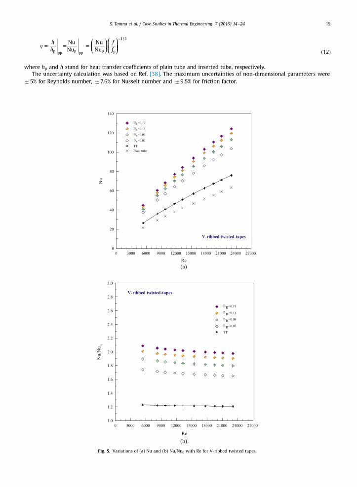
Fig. 7. Variation of η with Re for V-ribbed twisted tapes.

Fig. 8. Effect of BR on (a) Nu/Nu0, (b) f/f0 and (c) η at similar pumping power.
S. Tamna et al. / Case Studies in Thermal Engineering 7 (2016) 14–2422
4.4. Thermal performance
Fig. 7 depicts the variation of the thermal enhancement factor (η) with Re for the V-ribbed twisted tape with various BRvalues. In the figure, the measured Nu and f values of the tube insert and the plain tube are compared at the same pumpingpower. It is seen that η tends to decrease with increasing Re for all the cases and is about 1.1–1.4 depending on Re and BRvalues. The maximum η of about 1.4 is achieved for the V-ribbed twisted tape with BR¼0.09 and is higher than the otherV-ribbed twisted tapes around 1.7–8.2% while higher than the twisted tape alone at some 18.8–21.2%. A close examinationreveal that the V-ribbed twisted tape with BR¼0.09 performs better than the twisted tape alone around 20%. Therefore, ifthe choice of an insert device is the employ of double twisted tapes, V-ribs should be incorporated to obtain higher thermalperformance.
4.5. Effect oF BR
The thermal performance factor (η), indicating the practical benefit of the combined devices (V-ribbed twisted tape) isobtained from Eq. (12), in which heat transfer rate and friction factor in the tube with and without V-ribbed twisted tape,

Fig. 9. Validation test of (a) Nu and (b) f correlations with measured data.
S. Tamna et al. / Case Studies in Thermal Engineering 7 (2016) 14–24 23
are simultaneously determined at the same pumping power. Fig. 8a, b and c portray an effect of rib blockage ratio, BR onNu/Nu0, f/f0 and η, respectively. It is visible in the figure that the Nu/Nu0 increases with the increment of BR, especially forBR¼0.19, but with the reduction of Re. For V-ribbed twisted tapes, the average Nu/Nu0 and f/f0 values for the BR¼0.19 are,respectively, about 3.8% and 23.7%; 9.5% and 55%; 16.6% and 52.7% above those for the BR¼0.14, 0.09 and 0.07. The V-ribbedtwisted tapes with BR¼0.09 provides the maximum η of about 1.4 at the lowest Re.
In addition, the empirical correlations for Nu and f developed by relating the Re and BR together are compared withexperimental data within 77% deviation each, as can be seen in Fig. 9a and b, respectively. These correlations are valid forthe double V-ribbed co-twisted tapes with twist ratio of 4, Re¼5300–24,000, PR¼1.9 and BR¼0.07–0.19.
Correlations for double V-ribbed twisted tapes:
= ( )Nu 0.168 Re Pr B 150.701 0.4R
0.172
= ( )−f 5.494 Re B 160.263R
0.729
5. Conclusions
An experimental investigation on thermal characteristics in a constant heat-fluxed round tube fitted with doubleV-ribbed twisted-tape for turbulent flow, Re from 5300 to 24,000 has been carried out. The highest heat transfer andpressure loss from the V-ribbed twisted tape inserts is found at the largest BR. The Nu is in the range of 1.56–2.3 times whilethe f is 2.06–4.94 times above the plain tube for the V-ribbed twisted-tape. The inserted tube with V-ribbed twisted tape atBR¼0.19 gives the highest Nu and f. However, the V-ribbed twisted tape at BR¼0.09 yields the highest η around 1.4.Therefore, the use of the V-ribbed twisted tape is a promising enhancement device in the heat transfer improvement in aheating/cooling tube system.
Acknowledgment
The author would like to thank Mr. Chayodom Hinthao for data collection of this research.
References
[1] K. Yongsiri, P. Eiamsa-ard, K. Wongcharee, S. Eiamsa-ard, Augmented heat transfer in a turbulent channel flow with inclined detached-ribs, Case Stud.Therm. Eng. 3 (2014) 1–10.
[2] C. Thianpong, T. Chompookham, S. Skullong, P. Promvonge, Thermal characterization of turbulent flow in a channel with isosceles triangular ribs, Int.Commun. Heat Mass Transf. 36 (2009) 712–717.
[3] P. Promvonge, S. Skullong, S. Kwankaomeng, C. Thiangpong, Heat transfer in square duct fitted diagonally with angle-finned tape–Part 1: experimentalstudy, Int. Commun. Heat Mass Transf. 39 (5) (2012) 617–624.

S. Tamna et al. / Case Studies in Thermal Engineering 7 (2016) 14–2424
[4] P. Promvonge, S. Skullong, S. Kwankaomeng, C. Thiangpong, Heat transfer in square duct fitted diagonally with angle-finned tape–Part 2: numericalstudy, Int. Commun. Heat Mass Transf. 39 (2012) 625–633.
[5] S. Skullong, C. Thianpong, N. Jayranaiwachira, P. Promvonge, Experimental and numerical heat transfer investigation in turbulent square-duct flowthrough oblique horseshoe baffles, Chem. Eng. Process.: Process. Intensif. 99 (2016) 58–71.
[6] P. Promvonge, C. Khanoknaiyakarn, S. Kwankaomeng, C. Thianpong, Thermal behavior in solar air heater channel fitted with combined rib and delta-winglet, Int. Commun. Heat Mass Transf. 38 (2011) 749–756.
[7] S. Eiamsa-ard, S. Rattanawong, P. Promvonge, Turbulent convection in round tube equipped with propeller type swirl generators, Int. Commun. HeatMass Transf. 36 (2009) 357–364.
[8] S. Skullong, S. Kwankaomeng, C. Thianpong, P. Promvonge, Thermal performance of turbulent flow in a solar air heater channel with rib-grooveturbulators, Int. Commun. Heat Mass Transf. 50 (2014) 34–43.
[9] P. Promvonge, Thermal performance in circular tube fitted with coiled square wires, Energy Convers. Manag. 49 (2008) 980–987.[10] P. Naphon, Effect of coil-wire insert on heat transfer enhancement and pressure drop of the horizontal concentric tubes, Int. Commun. Heat Mass
Transf. 33 (2006) 753–763.[11] M.M.K. Bhuiya, M.S.U. Chowdhury, M. Saha, M.T. Islam, Heat transfer and friction factor characteristics in turbulent flow through a tube fitted with
perforated twisted tape inserts, Int. Commun. Heat Mass Transf. 46 (2013) 49–57.[12] P. Eiamsa-ard, N. Piriyarungroj, C. Thianpong, S. Eiamsa-ard, A case study on thermal performance assessment of a heat exchanger tube equipped with
regularly-spaced twisted tapes as swirl generators, Case Stud. Therm. Eng. 3 (2014) 86–102.[13] Y. Wang, Y.L. He, Y.G. Lei, J. Zhang, Heat transfer and hydrodynamics analysis of a novel dimpled tube, Exp. Therm. Fluid Sci. 34 (8) (2010) 1273–1281.[14] A. García, J.P. Solano, P.G. Vicente, A. Viedma, The influence of artificial roughness shape on heat transfer enhancement: Corrugated tubes, dimpled
tubes and wire coils, Appl. Therm. Eng. 35 (2012) 196–201.[15] P. Promvonge, Thermal enhancement in a round tube with snail entry and coiled-wire inserts, Int. Commun. Heat Mass Transf. 35 (2008) 623–629.[16] S. Eiamsa-ard, P. Promvonge, Performance assessment in a heat exchanger tube with alternate clockwise and counter-clockwise twisted-tape inserts,
Int. J. Heat Mass Transf. 53 (7–8) (2010) 1364–1372.[17] V.S. Harsha, S.V. Prabhu, R.P. Vedula, Influence of rib height on the local heat transfer distribution and pressure drop in a square channel with 90°
continuous and 60° V-broken ribs, Appl. Therm. Eng. 29 (11–12) (2009) 2444–2459.[18] S. Tamna, S. Skullong, C. Thianpong, P. Promvonge, Heat transfer behaviors in a solar air heater channel with multiple V-baffle vortex generators, Sol.
Energy 110 (2014) 720–735.[19] G. Zhou, Q. Ye, Experimental investigations of thermal and flow characteristics of curved trapezoidal winglet type vortex generators, Appl. Therm. Eng.
37 (2012) 241–248.[20] P. Promvonge, Thermal augmentation in circular tube with twisted tape and wire coil turbulators, Energy Convers. Manag. 49 (11) (2008) 2949–2955.[21] S. Gunes, V. Ozceyhan, O. Buyukalaca, The experimental investigation of heat transfer and pressure drop in a tube with coiled wire inserts placed
separately from the tube wall, Appl. Therm. Eng. 30 (2010) 1719–1725.[22] P. Promvonge, S. Tamna, M. Pimsarn, C. Thianpong, Thermal characterization in a circular tube fitted with inclined horseshoe baffles, Appl. Therm. Eng.
75 (2015) 1147–1155.[23] P. Promvonge, N. Koolnapadol, M. Pimsarn, C. Thianpong, Thermal performance enhancement in a heat exchanger tube fitted with inclined vortex
rings, Appl. Therm. Eng. 62 (2014) 285–292.[24] P. Promvonge, S. Suwannapan, M. Pimsarn, C. Thianpong, Experimental study on heat transfer in square duct with combined twisted-tape and winglet
vortex generators, Int. Commun. Heat Mass Transf. 59 (2014) 158–165.[25] S. Eiamsa-ard, C. Thianpong, P. Promvonge, Experimental investigation of heat transfer and flow friction in a circular tube fitted with regularly spaced
twisted tape elements, Int. Commun. Heat Mass Transf. 33 (10) (2006) 1225–1233.[26] S.R. Krishna, G. Pathipaka, P. Sivashanmugam, Heat transfer and pressure drop studies in a circular tube fitted with straight full twist, Exp. Therm.
Fluid Sci. 33 (3) (2009) 431–438.[27] P. Murugesan, K. Mayilsamy, S. Suresh, Heat transfer and friction factor studies in a circular tube fitted with twisted tape consisting of wire-nails, Chin.
J. Chem. Eng. 18 (6) (2010) 1038–1042.[28] K. Wongcharee, S. Eiamsa-ard, Heat transfer enhancement by twisted tapes with alternate-axes and triangular, rectangular and trapezoidal wings,
Chem. Eng. Process.: Process. Intensif. 50 (2011) 211–219.[29] S. Eiamsa-ard, Study on thermal and fluid flow characteristics in turbulent channel flows with multiple twisted tape vortex generators, Int. Commun.
Heat Mass Transf. 31 (2010) 644–651.[30] P. Bharadwaj, A.D. Khondge, A.W. Date, Heat transfer and pressure drop in a spirally grooved tube with twisted tape insert, Int. J. Heat Mass Transf. 52
(2009) 1938–1944.[31] S. Ray, A.W. Date, Friction and heat transfer characteristics of flow through square duct with twisted tape insert, Int. J. Heat Mass Transf. 46 (2003)
889–902.[32] Y.W. Chiu, J.Y. Jang, 3D numerical and experimental analysis for thermal–hydraulic characteristics of air flow inside a circular tube with different tube
inserts, Appl. Therm. Eng. 29 (2–3) (2009) 250–258.[33] S. Eiamsa-ard, K. Wongcharee, S. Sripattanapipat, 3-D Numerical simulation of swirling flow and convective heat transfer in a circular tube induced by
means of loose-fit twisted tapes, Int. Commun. Heat Mass Transf. 36 (9) (2009) 947–955.[34] W. Liu, K. Yang, Z.C. Liu, T.Z. Ming, A.W. Fan, C. Yang, Mechanism of heat transfer enhancement in the core flow of a tube and its numerical simulation,
Open. Transp. Phenom. J. 2 (2010) 9–15.[35] J. Guo, A.W. Fan, X.Y. Zhang, W. Liu, A numerical study on heat transfer and friction factor characteristics of laminar flow in a circular tube fitted with
center-cleared twisted tape, Int. J. Therm. Sci. 50 (2011) 1263–1270.[36] X.Y. Zhang, Z.C. Liu, W. Liu, Numerical studies on heat transfer and flow characteristics for laminar flow in a tube with multiple regularly spaced
twisted tapes, Int. J. Therm. Sci. 58 (2012) 157–167.[37] Y.X. Hong, X.H. Deng, L.S. Zhang, 3D numerical study on compound heat transfer enhancement of converging-diverging tubes equipped with twin
twisted tapes, Chin. J. Chem. Eng. 20 (3) (2012) 589–601.[38] ANSI/ASME, Measurement uncertainty. PTC 19, Part I, 1986, 1–1985.[39] F.P. Incropera, P.D. Dewitt, T.L. Bergman and A.S. Lavine, Foundations of Heat Transfer, 6th edition, 2013, John Wiley & Sons Singapore Pte. Ltd.