Embed Size (px)
Citation preview
Date: November 2015
Case Management Model and Notation
Version 1.1 RTF document
OMG Document Number: dtc/2015-12-04Standard document URL: http://www.omg.org/spec/CMMN/1.1/Machine Consumable Files:
Normative: http://www.omg.org/spec/CMMN/20151109/CMMN11.xmihttp://www.omg.org/spec/CMMN/20151109/CMMNDI11.xmihttp://www.omg.org/spec/CMMN/20151109/CMMNDI11.xsdhttp://www.omg.org/spec/CMMN/20151109/DC.xsdhttp://www.omg.org/spec/CMMN/20151109/CMMNDI.xsdhttp://www.omg.org/spec/CMMN/20151109/CMMN11.xsdhttp://www.omg.org/spec/CMMN/20151109/CMMN11CaseModel.xsd
O B J E C T M A N A G E M E N T G R O U PO B J E C T M A N A G E M E N T G R O U P

Copyright © 2011, Agile Enterprise Design, LLCCopyright © 2011, BizAgi LimitedCopyright © 2011, Cordys Nederland BVCopyright © 2011, International Business Machines CorporationCopyright © 2011, Kofax plcCopyright © 2014, Object Management Group, Inc.Copyright © 2011, Oracle IncorporatedCopyright © 2011, SAP AGCopyright © 2011, Stiftelsen SINTEFCopyright © 2011, TIBCOCopyright © 2011, Trisotech
USE OF SPECIFICATION - TERMS, CONDITIONS & NOTICES
The material in this document details an Object Management Group specification in accordance with the terms, conditions and notices set forth below. This document does not represent a commitment to implement any portion of this specification in any company's products. The information contained in this document is subject to change without notice.
LICENSES
The companies listed above have granted to the Object Management Group, Inc. (OMG) a nonexclusive, royalty-free, paid up, worldwide license to copy and distribute this document and to modify this document and distribute copies of the modified version. Each of the copyright holders listed above has agreed that no person shall be deemed to have infringed the copyright in the included material of any such copyright holder by reason of having used the specification set forth herein or having conformed any computer software to the specification.
Subject to all of the terms and conditions below, the owners of the copyright in this specification hereby grant you a fully-paid up, non-exclusive, nontransferable, perpetual, worldwide license (without the right to sublicense), to use this specification to create and distribute software and special purpose specifications that are based upon this specification, and to use, copy, and distribute this specification as provided under the Copyright Act; provided that: (1) both the copyright notice identified above and this permission notice appear on any copies of this specification; (2) the use of the specifications is for informational purposes and will not be copied or posted on any network computer or broadcast in any media and will not be otherwise resold or transferred for commercial purposes; and (3) no modifications are made to this specification. This limited permission automatically terminates without notice if you breach any of these terms or conditions. Upon termination, you will destroy immediately any copies of the specifications in your possession or control.
PATENTS
The attention of adopters is directed to the possibility that compliance with or adoption of OMG specifications may require use of an invention covered by patent rights. OMG shall not be responsible for identifying patents for which a license may be required by any OMG specification, or for conducting legal inquiries into the legal validity or scope of those patents that are brought to its attention. OMG specifications are prospective and advisory only. Prospective users are responsible for protecting themselves against liability for infringement of patents.
GENERAL USE RESTRICTIONS
Any unauthorized use of this specification may violate copyright laws, trademark laws, and communications regulations and statutes. This document contains information which is protected by copyright. All Rights Reserved. No part of this work covered by copyright herein may be reproduced or used in any form or by any means--graphic, electronic, or mechanical, including photocopying, recording, taping, or information storage and retrieval systems--without permission of the copyright owner.
DISCLAIMER OF WARRANTY
WHILE THIS PUBLICATION IS BELIEVED TO BE ACCURATE, IT IS PROVIDED "AS IS" AND MAY CONTAIN ERRORS OR MISPRINTS. THE OBJECT MANAGEMENT GROUP AND THE COMPANIES LISTED ABOVE MAKE NO WARRANTY OF ANY KIND, EXPRESS OR IMPLIED, WITH REGARD TO THIS PUBLICATION, INCLUDING BUT NOT LIMITED TO ANY WARRANTY OF TITLE OR OWNERSHIP, IMPLIED WARRANTY OF MERCHANTABILITY OR WARRANTY OF FITNESS FOR A PARTICULAR PURPOSE OR USE. IN NO EVENT SHALL THE OBJECT MANAGEMENT GROUP OR ANY OF THE COMPANIES LISTED ABOVE BE LIABLE FOR ERRORS CONTAINED HEREIN OR FOR DIRECT, INDIRECT, INCIDENTAL, SPECIAL, CONSEQUENTIAL, RELIANCE OR COVER DAMAGES, INCLUDING LOSS OF PROFITS, REVENUE, DATA OR USE, INCURRED BY ANY USER OR ANY THIRD PARTY IN CONNECTION WITH THE FURNISHING, PERFORMANCE, OR USE OF THIS MATERIAL, EVEN IF ADVISED OF THE POSSIBILITY OF SUCH DAMAGES.
The entire risk as to the quality and performance of software developed using this specification is borne by you. This disclaimer of warranty constitutes an essential part of the license granted to you to use this specification.
RESTRICTED RIGHTS LEGEND
Use, duplication or disclosure by the U.S. Government is subject to the restrictions set forth in subparagraph (c) (1) (ii) of The Rights in Technical Data and Computer Software Clause at DFARS 252.227-7013 or in subparagraph (c)(1) and (2) of the Commercial Computer Software - Restricted Rights clauses at 48 C.F.R. 52.227-19 or as specified in 48 C.F.R. 227-7202-2 of the DoD F.A.R. Supplement and its successors, or as specified in 48 C.F.R. 12.212 of the Federal Acquisition Regulations and its successors, as applicable. The specification copyright owners are as indicated above and may be contacted through the Object Management Group, 109 Highland Avenue, Needham, MA 02494, U.S.A.
TRADEMARKS
IMM®, MDA®, Model Driven Architecture®, UML®, UML Cube logo®, OMG Logo®, CORBA® and XMI® are registered trademarks of the Object Management Group, Inc., and Object Management Group™, OMG™ , Unified Modeling Language™, Model Driven Architecture Logo™, Model Driven Architecture Diagram™, CORBA logos™, XMI Logo™, CWM™, CWM Logo™, IIOP™ , MOF™ , OMG Interface Definition Language (IDL)™ , and OMG Systems Modeling Language (OMG SysML)™ are trademarks of the Object Management Group. All other products or company names mentioned are used for identification purposes only, and may be trademarks of their respective owners.
COMPLIANCE
The copyright holders listed above acknowledge that the Object Management Group (acting itself or through its designees) is and shall at all times be the sole entity that may authorize developers, suppliers and sellers of computer software to use certification marks, trademarks or other special designations to indicate compliance with these materials.
Software developed under the terms of this license may claim compliance or conformance with this specification if and only if the software compliance is of a nature fully matching the applicable compliance points as stated in the specification. Software developed only partially matching the applicable compliance points may claim only that the software was based on this speci-fication, but may not claim compliance or conformance with this specification. In the event that testing suites are implemented or approved by Object Management Group, Inc., software developed using this specification may claim compliance or confor-mance with the specification only if the software satisfactorily completes the testing suites.

OMG’s Issue Reporting Procedure
All OMG specifications are subject to continuous review and improvement. As part of this process we encourage readers to report any ambiguities, inconsistencies, or inaccuracies they may find by completing the Issue Reporting Form listed on the main web page http://www.omg.org, under Documents, Report a Bug/Issue (http://www.omg.org/report_issue.htm).
Table of Contents
List of Figures ...........................................................................................v
List of Tables ........................................................................................... ix
Preface ....................................................................................................xi
1 Scope ........................................................................................................... 1
2 Conformance ............................................................................................... 12.1 General ..........................................................................................................12.2 Visual Notation Conformance ........................................................................22.3 Case Modeling Conformance ........................................................................32.4 BPMN Compatibility Conformance ................................................................32.5 DMN Compatibility Conformance ..................................................................42.6 CMMN Complete Conformance ....................................................................4
3 References ................................................................................................... 43.1 Normative References ...................................................................................43.2 Non-normative References ............................................................................4
4 Additional Information .................................................................................. 54.1 General Concept ...........................................................................................54.2 Target Users ..................................................................................................74.3 Interoperability ...............................................................................................74.4 Submitting and Supporting Organizations .....................................................74.5 IPR and Patents ............................................................................................84.6 Guide to the Specification ..............................................................................8
5 Case Management Elements ....................................................................... 95.1 Core Infrastructure .........................................................................................9
5.1.1 CMMNElement ........................................................................................................ 9 5.1.1.1 Documentation ..................................................................................................... 10
5.1.2 Definitions ............................................................................................................. 10 5.1.3 Import .................................................................................................................... 13 5.1.4 CaseFileItemDefinition .......................................................................................... 13
5.1.4.1 Property ................................................................................................................ 14 5.1.5 Extensibility ........................................................................................................... 15
5.1.5.1 Extension ............................................................................................................. 16 5.1.5.2 ExtensionDefinition ..............................................................................................16 5.1.5.3 ExtensionAttributeDefinition ................................................................................. 16
5.1.6 External Relationships .......................................................................................... 175.2 Case Model Elements ................................................................................. 18
5.2.1 Case ...................................................................................................................... 19 5.2.2 Role ....................................................................................................................... 19
Case Management Model and Notation, v1.1 i
5.3 Information Model Elements 20 5.3.1 CaseFile ................................................................................................................ 20 5.3.2 CaseFileItem ......................................................................................................... 21
5.3.2.1 Versioning ............................................................................................................22
5.4 Plan Model Elements ...................................................................................22 5.4.1 PlanItemDefinition ................................................................................................. 22 5.4.2 EventListener ........................................................................................................ 24
5.4.2.1 TimerEventListener ..............................................................................................25 5.4.2.2 UserEventListener ................................................................................................26
5.4.3 Milestone ............................................................................................................... 26 5.4.4 PlanFragment ........................................................................................................ 26 5.4.5 PlanItem ................................................................................................................ 28
5.4.5.1 Criterion ................................................................................................................29 5.4.5.2 Entry Criterion ......................................................................................................29 5.4.5.3 Exit Criterion .........................................................................................................29 5.4.5.4 PlanItemDefinition Reference Constraint Example ..............................................29
5.4.6 Sentry .................................................................................................................... 30 5.4.6.1 OnPart ..................................................................................................................32 5.4.6.2 CaseFileItemOnPart .............................................................................................32 5.4.6.3 PlanItemOnPart ....................................................................................................33 5.4.6.4 IfPart .....................................................................................................................34
5.4.7 Expressions ........................................................................................................... 35 5.4.8 Stage ..................................................................................................................... 35 5.4.9 PlanningTable ....................................................................................................... 36
5.4.9.1 TableItem .............................................................................................................38 5.4.9.2 DiscretionaryItem .................................................................................................39 5.4.9.3 Applicability Rules ................................................................................................41
5.4.10 Task .................................................................................................................... 41 5.4.10.1 Parameter ..........................................................................................................43 5.4.10.2 ParameterMapping .............................................................................................43 5.4.10.3 CaseParameter ..................................................................................................43 5.4.10.4 HumanTask ........................................................................................................44 5.4.10.5 ProcessTask ......................................................................................................45 5.4.10.6 CaseTask ...........................................................................................................47 5.4.10.7 Decision Task .....................................................................................................48
5.4.11 PlanItemControl .................................................................................................. 49 5.4.11.1 ManualActivationRule ........................................................................................51 5.4.11.2 RequiredRule .....................................................................................................52 5.4.11.3 RepetitionRule ....................................................................................................52
5.5 Artifacts .......................................................................................................53 5.5.1 Association ............................................................................................................ 54 5.5.2 Text Annotation .................................................................................................... 55
6 Notation ...................................................................................................... 576.1 Introduction ..................................................................................................576.2 Case ............................................................................................................576.3 Case Plan Models ........................................................................................576.4 Case File Items ............................................................................................586.5 Stages ..........................................................................................................596.6 Entry and Exit Criterion ................................................................................596.7 Plan Fragments ...........................................................................................60
ii Case Management Model and Notation, v1.1
6.8 Tasks ...........................................................................................................61 6.8.1 Human Task .......................................................................................................... 62 6.8.2 Case Task ............................................................................................................. 62
6.8.2.1 Case Task for BPMN Compatibility Conformance ...............................................63 6.8.3 Process Task ........................................................................................................ 63
6.8.3.1 Process Task for BPMN Compatibility Conformance ...........................................64 6.8.4 Decision Task ........................................................................................................ 64
6.8.4.1 Decision Task for DMN Compatibility Conformance ............................................65
6.9 Milestones ...................................................................................................666.10 EventListeners ...........................................................................................666.11 Links .........................................................................................................66
6.11.1 Connector Usage ................................................................................................ 686.12 Planning Table ..........................................................................................706.13 Decorators .................................................................................................73
6.13.1 AutoComplete Decorator ..................................................................................... 73 6.13.2 ManualActivation Decorator ................................................................................ 74 6.13.3 Required Decorator ............................................................................................. 75 6.13.4 Repetition Decorator ........................................................................................... 76 6.13.5 Decorator Applicability Summary ........................................................................ 76
6.14 Artifacts ...................................................................................................... 79 6.14.1 Association .......................................................................................................... 79 6.14.2 Text Annotation ................................................................................................... 79
6.15 Examples ...................................................................................................80
7 CMMN Diagram Interchange (DMMN DI) .................................................. 817.1 Scope ..........................................................................................................817.2 Diagram Definition and Interchange ............................................................ 817.3 How to read this chapter ..............................................................................817.4 CMMN Diagram Interchange Meta-Model ...................................................82
7.4.1 Overview ............................................................................................................... 82 7.4.2 Measurement Unit ................................................................................................. 82 7.4.3 CMMNDI [Class] ................................................................................................... 82 7.4.4 CMMNDiagram [Class] ......................................................................................... 83 7.4.5 CMMNDiagramElement [Class] ............................................................................ 84 7.4.6 CMMNShape [Class] ............................................................................................. 85 7.4.7 CMMNEdge [Class] ............................................................................................... 86 7.4.8 CMMNLabel [Class] .............................................................................................. 88 7.4.9 CMMNStyle [Class] ............................................................................................... 88
7.5 Notational Depiction Library and Abstract Element Resolutions .................90 7.5.1 Labels ................................................................................................................... 90 7.5.2 CMMNShape Resolution ....................................................................................... 91
7.5.2.1 Case Plan Model .................................................................................................. 91 7.5.2.2 Plan Item and Discretionary Items .......................................................................92 7.5.2.3 Auto CompleteDecorator ......................................................................................94 7.5.2.4 ItemControl Decorators ........................................................................................95 7.5.2.5 Planning Table Decorator .................................................................................... 98 7.5.2.6 Entry criterion .......................................................................................................99 7.5.2.7 Exit criterion ....................................................................................................... 100 7.5.2.8 Case File Item ....................................................................................................100 7.5.2.9 Artifacts .............................................................................................................. 101
Case Management Model and Notation, v1.1 iii
7.5.3 CMMNEdge Resolution ....................................................................................... 101 7.5.3.1 On Part Connector referring to CaseFileItemOnPart .........................................101 7.5.3.2 On Part Connector referring to PlanItemOnPart ................................................101 7.5.3.3 Discretionary Association ...................................................................................102 7.5.3.4 Association .........................................................................................................103
8 Execution Semantics ............................................................................... 1058.1 Introduction ................................................................................................1058.2 Case Instance ............................................................................................1058.3 CaseFileItem Lifecycle ...............................................................................105
8.3.1 CaseFileItem operations ..................................................................................... 1068.4 CasePlanModel Lifecycles .........................................................................108
8.4.1 Case Instance Lifecyle ........................................................................................ 109 8.4.2 Stage and Task Lifecycle .................................................................................... 111 8.4.3 EventListener and Milestone Lifecycle ................................................................ 117
8.5 Sentry ........................................................................................................1188.6 Behavior Property Rules ............................................................................119
8.6.1 Stage.autoComplete ........................................................................................... 119 8.6.2 ManualActivationRule ......................................................................................... 120 8.6.3 RequiredRule ...................................................................................................... 120 8.6.4 RepetitionRule ..................................................................................................... 120 8.6.5 ApplicabilityRule .................................................................................................. 121
8.7 Planning .....................................................................................................1218.8 Connector ..................................................................................................122
9 Exchange Formats ................................................................................... 1239.1 Interchanging Incomplete Models ..............................................................1239.2 Machine Readable Files ............................................................................1239.3 XSD ...........................................................................................................123
9.3.1 Document Structure ............................................................................................ 123 9.3.2 References within CMMN XSD ........................................................................... 123
iv Case Management Model and Notation, v1.1
List of Figures
Figure 4.1 - Design-time phase modeling and run-time phase planning. . . . . . . . . . . . . . . . . . . . . . . . . . . . . . . . . 6Figure 5.1 - CMMNElement class diagram . . . . . . . . . . . . . . . . . . . . . . . . . . . . . . . . . . . . . . . . . . . . . . . . . . . . . . . . 9Figure 5.2- Definitions class diagram . . . . . . . . . . . . . . . . . . . . . . . . . . . . . . . . . . . . . . . . . . . . . . . . . . . . . . . . . . . 11Figure 5.3- Extensibility diagram . . . . . . . . . . . . . . . . . . . . . . . . . . . . . . . . . . . . . . . . . . . . . . . . . . . . . . . . . . . . . . 15Figure 5.4- Case class diagram . . . . . . . . . . . . . . . . . . . . . . . . . . . . . . . . . . . . . . . . . . . . . . . . . . . . . . . . . . . . . . . . 18Figure 5.5- CaseFile class diagram . . . . . . . . . . . . . . . . . . . . . . . . . . . . . . . . . . . . . . . . . . . . . . . . . . . . . . . . . . . . . 20Figure 5.6- PlanItemDefinition class diagram . . . . . . . . . . . . . . . . . . . . . . . . . . . . . . . . . . . . . . . . . . . . . . . . . . . . . 23Figure 5.7- EventListener class diagram . . . . . . . . . . . . . . . . . . . . . . . . . . . . . . . . . . . . . . . . . . . . . . . . . . . . . . . . . 24Figure 5.8- PlanFragment class diagram . . . . . . . . . . . . . . . . . . . . . . . . . . . . . . . . . . . . . . . . . . . . . . . . . . . . . . . . . 27Figure 5.9- Sentry class diagram . . . . . . . . . . . . . . . . . . . . . . . . . . . . . . . . . . . . . . . . . . . . . . . . . . . . . . . . . . . . . . . 31Figure 5.10- Stage class diagram . . . . . . . . . . . . . . . . . . . . . . . . . . . . . . . . . . . . . . . . . . . . . . . . . . . . . . . . . . . . . . . 35Figure 5.11- PlanningTable class diagram . . . . . . . . . . . . . . . . . . . . . . . . . . . . . . . . . . . . . . . . . . . . . . . . . . . . . . . 37Figure 5.12- Task class diagram . . . . . . . . . . . . . . . . . . . . . . . . . . . . . . . . . . . . . . . . . . . . . . . . . . . . . . . . . . . . . . . 42Figure 5.13- PlanItemControl class diagram . . . . . . . . . . . . . . . . . . . . . . . . . . . . . . . . . . . . . . . . . . . . . . . . . . . . . 50Figure 5.14- Artifacts class diagram . . . . . . . . . . . . . . . . . . . . . . . . . . . . . . . . . . . . . . . . . . . . . . . . . . . . . . . . . . . . 54Figure 6.1 - CasePlanModel Shape . . . . . . . . . . . . . . . . . . . . . . . . . . . . . . . . . . . . . . . . . . . . . . . . . . . . . . . . . . . . . 57Figure 6.2- CasePlanModel Example . . . . . . . . . . . . . . . . . . . . . . . . . . . . . . . . . . . . . . . . . . . . . . . . . . . . . . . . . . . 58Figure 6.3- CaseFileItem Shape . . . . . . . . . . . . . . . . . . . . . . . . . . . . . . . . . . . . . . . . . . . . . . . . . . . . . . . . . . . . . . . 58Figure 6.4- Collapsed Stage and Expanded Stage Shapes . . . . . . . . . . . . . . . . . . . . . . . . . . . . . . . . . . . . . . . . . . . . 59Figure 6.5- Discretionary Collapsed Stage and Discretionary Expanded Stage Shapes . . . . . . . . . . . . . . . . . . . . . 59Figure 6.6- EntryCriterion Shape . . . . . . . . . . . . . . . . . . . . . . . . . . . . . . . . . . . . . . . . . . . . . . . . . . . . . . . . . . . . . . 60Figure 6.7- ExitCriterion Shape . . . . . . . . . . . . . . . . . . . . . . . . . . . . . . . . . . . . . . . . . . . . . . . . . . . . . . . . . . . . . . . 60Figure 6.8- Collapsed and Expanded versions of a Stage with two entry criterion, one sub Stage and three Tasks 60Figure 6.9- Collapsed PlanFragment and Expanded PlanFragment Shapes . . . . . . . . . . . . . . . . . . . . . . . . . . . . . 61Figure 6.10- Task Shape . . . . . . . . . . . . . . . . . . . . . . . . . . . . . . . . . . . . . . . . . . . . . . . . . . . . . . . . . . . . . . . . . . . . . 61Figure 6.11- Discretionary Task . . . . . . . . . . . . . . . . . . . . . . . . . . . . . . . . . . . . . . . . . . . . . . . . . . . . . . . . . . . . . . . 61Figure 6.12- Task with one entry criterion and one exit criterion . . . . . . . . . . . . . . . . . . . . . . . . . . . . . . . . . . . . . . 61Figure 6.13- Non-blocking HumanTask Shape . . . . . . . . . . . . . . . . . . . . . . . . . . . . . . . . . . . . . . . . . . . . . . . . . . . . 62Figure 6.14- Blocking HumanTask Shape . . . . . . . . . . . . . . . . . . . . . . . . . . . . . . . . . . . . . . . . . . . . . . . . . . . . . . . 62Figure 6.15- Non-Blocking and Blocking Discretionary HumanTasks . . . . . . . . . . . . . . . . . . . . . . . . . . . . . . . . . 62Figure 6.16- CaseTask Shape . . . . . . . . . . . . . . . . . . . . . . . . . . . . . . . . . . . . . . . . . . . . . . . . . . . . . . . . . . . . . . . . . 62Figure 6.17- Discretionary CaseTask Shape . . . . . . . . . . . . . . . . . . . . . . . . . . . . . . . . . . . . . . . . . . . . . . . . . . . . . . 63Figure 6.18- Alternative CaseTask shape . . . . . . . . . . . . . . . . . . . . . . . . . . . . . . . . . . . . . . . . . . . . . . . . . . . . . . . . 63Figure 6.19- Alternative Discretionary CaseTask shape . . . . . . . . . . . . . . . . . . . . . . . . . . . . . . . . . . . . . . . . . . . . . 63Figure 6.20- ProcessTask Shape . . . . . . . . . . . . . . . . . . . . . . . . . . . . . . . . . . . . . . . . . . . . . . . . . . . . . . . . . . . . . . . 63Figure 6.21- Discretionary ProcessTask Shape . . . . . . . . . . . . . . . . . . . . . . . . . . . . . . . . . . . . . . . . . . . . . . . . . . . . 64Figure 6.22 - Alternative ProcessTask Shapes . . . . . . . . . . . . . . . . . . . . . . . . . . . . . . . . . . . . . . . . . . . . . . . . . . . . 64Figure 6.23- Alternative Discretionary ProcessTask Shapes . . . . . . . . . . . . . . . . . . . . . . . . . . . . . . . . . . . . . . . . . 64Figure 6.24- Decision Task Shapes . . . . . . . . . . . . . . . . . . . . . . . . . . . . . . . . . . . . . . . . . . . . . . . . . . . . . . . . . . . . . 64Figure 6.25- Discretionary Decision Task Shapes . . . . . . . . . . . . . . . . . . . . . . . . . . . . . . . . . . . . . . . . . . . . . . . . . 65Figure 6.26- Decision Task Shapes for DMN Compatibility . . . . . . . . . . . . . . . . . . . . . . . . . . . . . . . . . . . . . . . . . 65Figure 6.27- Discretionary Decision Task Shapes for DMN Compatibility . . . . . . . . . . . . . . . . . . . . . . . . . . . . . . 65Figure 6.28- Milestone Shape . . . . . . . . . . . . . . . . . . . . . . . . . . . . . . . . . . . . . . . . . . . . . . . . . . . . . . . . . . . . . . . . . 66
Case Management Model and Notation, v1.1 v
Figure 6.29- Milestone with one entry criterion . . . . . . . . . . . . . . . . . . . . . . . . . . . . . . . . . . . . . . . . . . . . . . . . . . .66Figure 6.30- EventListener Shape . . . . . . . . . . . . . . . . . . . . . . . . . . . . . . . . . . . . . . . . . . . . . . . . . . . . . . . . . . . . . .66Figure 6.31- TimerEventListener Shape . . . . . . . . . . . . . . . . . . . . . . . . . . . . . . . . . . . . . . . . . . . . . . . . . . . . . . . . .66Figure 6.32- UserEventListener Shape . . . . . . . . . . . . . . . . . . . . . . . . . . . . . . . . . . . . . . . . . . . . . . . . . . . . . . . . . .66Figure 6.33- Connector Shape . . . . . . . . . . . . . . . . . . . . . . . . . . . . . . . . . . . . . . . . . . . . . . . . . . . . . . . . . . . . . . . . .67Figure 6.34- Sentry-based dependency between two Tasks . . . . . . . . . . . . . . . . . . . . . . . . . . . . . . . . . . . . . . . . . . 67Figure 6.35- Discretionary Association . . . . . . . . . . . . . . . . . . . . . . . . . . . . . . . . . . . . . . . . . . . . . . . . . . . . . . . . . .67Figure 6.36- Dependency between a blocking HumanTask and its associated Discretionary Tasks . . . . . . . . . . .68Figure 6.37- Using Sentry-based connectors to visualize "AND" . . . . . . . . . . . . . . . . . . . . . . . . . . . . . . . . . . . . . .68Figure 6.38- Using Sentry-based connectors to visualize "OR" . . . . . . . . . . . . . . . . . . . . . . . . . . . . . . . . . . . . . . .69Figure 6.39- Using Sentry-based connector to visualize dependency between Stages . . . . . . . . . . . . . . . . . . . . . .69Figure 6.40- Using the Sentry-based connector to visualize dependency between a Task and a Milestone . . . . . . . . . . . . . . . . . . . . . . . . . . . . . . . . . . . . . . . . . .70Figure 6.41- Using the Sentry-based connector to visualize dependency between a Task and a TimerEventListener . . . . . . . . . . . . . . . . . . . . . . . . . . . . . . . . . .70Figure 6.42- Using the Sentry-based connector to visualize dependency between a Task and a CaseFileItem . . . . . . . . . . . . . . . . . . . . . . . . . . . . . . . . . . . . . . .70Figure 6.43- PlanningTable with DiscretionaryItems Not Visualized Shape . . . . . . . . . . . . . . . . . . . . . . . . . . . . . . . . . . . . . . . . . . . . . . . . . . . . . . . . . . . . .70Figure 6.44- Planning Table with DiscretionaryItems Visualized Shape . . . . . . . . . . . . . . . . . . . . . . . . . . . . . . . . . . . . . . . . . . . . . . . . . . . . . . . . . . . . . . . .71Figure 6.45- Stage and Discretionary Stage with PlanningTable . . . . . . . . . . . . . . . . . . . . . . . . . . . . . . . . . . . . . .71Figure 6.46- Blocking HumanTask and Discretionary Blocking HumanTask with PlanningTable . . . . . . . . . . . . . . . . . . . . . . . . . . . . . . . . . . . . . . . . . . . . . . . . . . . .71Figure 6.47- Stage with PlanningTable Collapsed and Expanded . . . . . . . . . . . . . . . . . . . . . . . . . . . . . . . . . . . . . .71Figure 6.48- Blocking Human Task with DiscretionaryItems not expanded and expanded. . . . . . . . . . . . . . . . . . 72Figure 6.49- Collapsed Stage with Collapsed PlanningTable. . . . . . . . . . . . . . . . . . . . . . . . . . . . . . . . . . . . . . . . . 72Figure 6.50- Expanded Stage with Collapsed PlanningTable . . . . . . . . . . . . . . . . . . . . . . . . . . . . . . . . . . . . . . . . .72Figure 6.51- Expanded Stage with Expanded PlanningTable . . . . . . . . . . . . . . . . . . . . . . . . . . . . . . . . . . . . . . . . .73Figure 6.52- Expanded Stage with Expanded PlanningTable and Expanded HumanTask PlanningTable . . . . . . .73Figure 6.53- AutoComplete Decorator . . . . . . . . . . . . . . . . . . . . . . . . . . . . . . . . . . . . . . . . . . . . . . . . . . . . . . . . . . .73Figure 6.54- Stage Shape variations with AutoComplete Decorator . . . . . . . . . . . . . . . . . . . . . . . . . . . . . . . . . . . .74Figure 6.55- CasePlanModel with AutoComplete Decorator . . . . . . . . . . . . . . . . . . . . . . . . . . . . . . . . . . . . . . . . .74Figure 6.56- ManualActivation Decorator . . . . . . . . . . . . . . . . . . . . . . . . . . . . . . . . . . . . . . . . . . . . . . . . . . . . . . . .74Figure 6.57- ManualActivation Decorator example on Task and Stage . . . . . . . . . . . . . . . . . . . . . . . . . . . . . . . . .75Figure 6.58- Required Decorator Shape . . . . . . . . . . . . . . . . . . . . . . . . . . . . . . . . . . . . . . . . . . . . . . . . . . . . . . . . . .75Figure 6.59- Required Decorator example on Task and Stage . . . . . . . . . . . . . . . . . . . . . . . . . . . . . . . . . . . . . . . .75Figure 6.60- Required Decorator example on Milestone . . . . . . . . . . . . . . . . . . . . . . . . . . . . . . . . . . . . . . . . . . . . .75Figure 6.61- Repetition Decorator . . . . . . . . . . . . . . . . . . . . . . . . . . . . . . . . . . . . . . . . . . . . . . . . . . . . . . . . . . . . . .76Figure 6.62- Repetition Decorator example on Task and Stage . . . . . . . . . . . . . . . . . . . . . . . . . . . . . . . . . . . . . . .76Figure 6.63- Repetition Decorator example on Milestone . . . . . . . . . . . . . . . . . . . . . . . . . . . . . . . . . . . . . . . . . . . .76Figure 6.64- CasePlanModel Shape with all possible Decorators . . . . . . . . . . . . . . . . . . . . . . . . . . . . . . . . . . . . . .77Figure 6.65- Stage Shape with all possible Decorators . . . . . . . . . . . . . . . . . . . . . . . . . . . . . . . . . . . . . . . . . . . . . .78Figure 6.66- Task Shape with all possible Decorators . . . . . . . . . . . . . . . . . . . . . . . . . . . . . . . . . . . . . . . . . . . . . . .78Figure 6.67- Non-Blocking and Blocking HumanTask Shapes with all possible Decorators . . . . . . . . . . . . . . . . . . . . . . . . . . . . . . . . . . . . . . . . . . . . . . . . . . . . . . .78Figure 6.68- Milestone Shape with all possible Decorators . . . . . . . . . . . . . . . . . . . . . . . . . . . . . . . . . . . . . . . . . . .78
vi Case Management Model and Notation, v1.1
Figure 6.69- An Association . . . . . . . . . . . . . . . . . . . . . . . . . . . . . . . . . . . . . . . . . . . . . . . . . . . . . . . . . . . . . . . . . . 79Figure 6.70- A Directional Association . . . . . . . . . . . . . . . . . . . . . . . . . . . . . . . . . . . . . . . . . . . . . . . . . . . . . . . . . . 79Figure 6.71- An Association of Text Annotation . . . . . . . . . . . . . . . . . . . . . . . . . . . . . . . . . . . . . . . . . . . . . . . . . . 79Figure 6.72- A Text Annotation . . . . . . . . . . . . . . . . . . . . . . . . . . . . . . . . . . . . . . . . . . . . . . . . . . . . . . . . . . . . . . . 80Figure 6.73- Claims Management Example . . . . . . . . . . . . . . . . . . . . . . . . . . . . . . . . . . . . . . . . . . . . . . . . . . . . . . 80Figure 7.1 - CMMNDI . . . . . . . . . . . . . . . . . . . . . . . . . . . . . . . . . . . . . . . . . . . . . . . . . . . . . . . . . . . . . . . . . . . . . . . 82Figure 7.2- CMMNDiagram . . . . . . . . . . . . . . . . . . . . . . . . . . . . . . . . . . . . . . . . . . . . . . . . . . . . . . . . . . . . . . . . . . 83Figure 7.3- CMMNDiagramElement . . . . . . . . . . . . . . . . . . . . . . . . . . . . . . . . . . . . . . . . . . . . . . . . . . . . . . . . . . . 84Figure 7.4- CMMN Shape . . . . . . . . . . . . . . . . . . . . . . . . . . . . . . . . . . . . . . . . . . . . . . . . . . . . . . . . . . . . . . . . . . . . 85Figure 7.5- CMMN Edge . . . . . . . . . . . . . . . . . . . . . . . . . . . . . . . . . . . . . . . . . . . . . . . . . . . . . . . . . . . . . . . . . . . . . 86Figure 7.6- CMMN Label . . . . . . . . . . . . . . . . . . . . . . . . . . . . . . . . . . . . . . . . . . . . . . . . . . . . . . . . . . . . . . . . . . . . 88Figure 7.7- CMMNStyle . . . . . . . . . . . . . . . . . . . . . . . . . . . . . . . . . . . . . . . . . . . . . . . . . . . . . . . . . . . . . . . . . . . . . 88Figure 7.8- OnPart connector displaying the OnPart name and the Standard Event . . . . . . . . . . . . . . . . . . . . . . . . 91Figure 8.1- CaseFileItem instance lifecycle . . . . . . . . . . . . . . . . . . . . . . . . . . . . . . . . . . . . . . . . . . . . . . . . . . . . . 105Figure 8.2- Lifecycle of a Case instance . . . . . . . . . . . . . . . . . . . . . . . . . . . . . . . . . . . . . . . . . . . . . . . . . . . . . . . . 109Figure 8.3- Lifecycle of a Stage or Task instance . . . . . . . . . . . . . . . . . . . . . . . . . . . . . . . . . . . . . . . . . . . . . . . . . 111Figure 8.4- Lifecycle of an EventListener or Milestone instance . . . . . . . . . . . . . . . . . . . . . . . . . . . . . . . . . . . . 117
Case Management Model and Notation, v1.1 vii

viii Case Management Model and Notation, v1.1
List of Tables
Table 2.1- Conformance Matrix . . . . . . . . . . . . . . . . . . . . . . . . . . . . . . . . . . . . . . . . . . . . . . . . . . . . . . . . . . . . . . . . 2Table 5.1- CMMNElement Attributes . . . . . . . . . . . . . . . . . . . . . . . . . . . . . . . . . . . . . . . . . . . . . . . . . . . . . . . . . . . . 9Table 5.2- Definitions attributes . . . . . . . . . . . . . . . . . . . . . . . . . . . . . . . . . . . . . . . . . . . . . . . . . . . . . . . . . . . . . . . 11Table 5.3- Import attributes . . . . . . . . . . . . . . . . . . . . . . . . . . . . . . . . . . . . . . . . . . . . . . . . . . . . . . . . . . . . . . . . . . . 13Table 5.4- CaseFileItemDefinition attributes . . . . . . . . . . . . . . . . . . . . . . . . . . . . . . . . . . . . . . . . . . . . . . . . . . . . . 13Table 5.5- Definition Types and their URIs . . . . . . . . . . . . . . . . . . . . . . . . . . . . . . . . . . . . . . . . . . . . . . . . . . . . . . 14Table 5.6- Property attributes . . . . . . . . . . . . . . . . . . . . . . . . . . . . . . . . . . . . . . . . . . . . . . . . . . . . . . . . . . . . . . . . . 14Table 5.7- Property Types and their URIs . . . . . . . . . . . . . . . . . . . . . . . . . . . . . . . . . . . . . . . . . . . . . . . . . . . . . . . . 14Table 5.8- Extension attributes and model association . . . . . . . . . . . . . . . . . . . . . . . . . . . . . . . . . . . . . . . . . . . . . . 16Table 5.9- Extension attriutes and model association . . . . . . . . . . . . . . . . . . . . . . . . . . . . . . . . . . . . . . . . . . . . . . . 16Table 5.10- ExtensionAttributeDefinition attriutes and model association . . . . . . . . . . . . . . . . . . . . . . . . . . . . . . 17Table 5.11- ExtensionAttributeValue model association . . . . . . . . . . . . . . . . . . . . . . . . . . . . . . . . . . . . . . . . . . . . 17Table 5.12- Relationship attributes . . . . . . . . . . . . . . . . . . . . . . . . . . . . . . . . . . . . . . . . . . . . . . . . . . . . . . . . . . . . . 18Table 5.13- Case attributes . . . . . . . . . . . . . . . . . . . . . . . . . . . . . . . . . . . . . . . . . . . . . . . . . . . . . . . . . . . . . . . . . . . 19Table 5.14- Role attributes and model associations . . . . . . . . . . . . . . . . . . . . . . . . . . . . . . . . . . . . . . . . . . . . . . . . 20Table 5.15- CaseFile attributes and model associations . . . . . . . . . . . . . . . . . . . . . . . . . . . . . . . . . . . . . . . . . . . . . 21Table 5.16- CaseFileItem attributes . . . . . . . . . . . . . . . . . . . . . . . . . . . . . . . . . . . . . . . . . . . . . . . . . . . . . . . . . . . . . 21Table 5.17- PlanItemDefinition attributes . . . . . . . . . . . . . . . . . . . . . . . . . . . . . . . . . . . . . . . . . . . . . . . . . . . . . . . . 23Table 5.18- TimerEventListener attributes . . . . . . . . . . . . . . . . . . . . . . . . . . . . . . . . . . . . . . . . . . . . . . . . . . . . . . . 25Table 5.19- CaseFileItemStartTrigger attributes . . . . . . . . . . . . . . . . . . . . . . . . . . . . . . . . . . . . . . . . . . . . . . . . . . . 25Table 5.20- PlanItemStartTrigger attributes . . . . . . . . . . . . . . . . . . . . . . . . . . . . . . . . . . . . . . . . . . . . . . . . . . . . . . 26Table 5.21- UserEventListener attributes . . . . . . . . . . . . . . . . . . . . . . . . . . . . . . . . . . . . . . . . . . . . . . . . . . . . . . . . 26Table 5.22- PlanFragment attributes and model associations . . . . . . . . . . . . . . . . . . . . . . . . . . . . . . . . . . . . . . . . . 27Table 5.23- PlanItem attributes . . . . . . . . . . . . . . . . . . . . . . . . . . . . . . . . . . . . . . . . . . . . . . . . . . . . . . . . . . . . . . . . 28Table 5.24- Criterior attributes . . . . . . . . . . . . . . . . . . . . . . . . . . . . . . . . . . . . . . . . . . . . . . . . . . . . . . . . . . . . . . . . 29Table 5.25- Sentry attributes . . . . . . . . . . . . . . . . . . . . . . . . . . . . . . . . . . . . . . . . . . . . . . . . . . . . . . . . . . . . . . . . . . 32Table 5.26- OnPart attributes . . . . . . . . . . . . . . . . . . . . . . . . . . . . . . . . . . . . . . . . . . . . . . . . . . . . . . . . . . . . . . . . . . 32Table 5.27- CaseFileItemOnPart attributes . . . . . . . . . . . . . . . . . . . . . . . . . . . . . . . . . . . . . . . . . . . . . . . . . . . . . . . 32Table 5.28- CaseFileItemTransition enumeration . . . . . . . . . . . . . . . . . . . . . . . . . . . . . . . . . . . . . . . . . . . . . . . . . . 32Table 5.29- PlanItemOnPart attributes . . . . . . . . . . . . . . . . . . . . . . . . . . . . . . . . . . . . . . . . . . . . . . . . . . . . . . . . . . 33Table 5.30- PlanItemTransition enumeration . . . . . . . . . . . . . . . . . . . . . . . . . . . . . . . . . . . . . . . . . . . . . . . . . . . . . 34Table 5.31- IfPart attributes . . . . . . . . . . . . . . . . . . . . . . . . . . . . . . . . . . . . . . . . . . . . . . . . . . . . . . . . . . . . . . . . . . . 35Table 5.32- Expression attributes . . . . . . . . . . . . . . . . . . . . . . . . . . . . . . . . . . . . . . . . . . . . . . . . . . . . . . . . . . . . . . 35Table 5.33- Stage attributes . . . . . . . . . . . . . . . . . . . . . . . . . . . . . . . . . . . . . . . . . . . . . . . . . . . . . . . . . . . . . . . . . . . 36Table 5.34- PlanningTable attributes . . . . . . . . . . . . . . . . . . . . . . . . . . . . . . . . . . . . . . . . . . . . . . . . . . . . . . . . . . . . 38Table 5.35- TableItem attributes . . . . . . . . . . . . . . . . . . . . . . . . . . . . . . . . . . . . . . . . . . . . . . . . . . . . . . . . . . . . . . . 38Table 5.36- DiscretionaryItem attributes . . . . . . . . . . . . . . . . . . . . . . . . . . . . . . . . . . . . . . . . . . . . . . . . . . . . . . . . . 39Table 5.37- ApplicabilityRule attributes . . . . . . . . . . . . . . . . . . . . . . . . . . . . . . . . . . . . . . . . . . . . . . . . . . . . . . . . . 41Table 5.38- Task attributes and model associations . . . . . . . . . . . . . . . . . . . . . . . . . . . . . . . . . . . . . . . . . . . . . . . . 42Table 5.39- Parameter attributes . . . . . . . . . . . . . . . . . . . . . . . . . . . . . . . . . . . . . . . . . . . . . . . . . . . . . . . . . . . . . . . 43Table 5.40- ParameterMapping attributes . . . . . . . . . . . . . . . . . . . . . . . . . . . . . . . . . . . . . . . . . . . . . . . . . . . . . . . . 43Table 5.41- CaseParameter attributes . . . . . . . . . . . . . . . . . . . . . . . . . . . . . . . . . . . . . . . . . . . . . . . . . . . . . . . . . . . 44Table 5.42- HumanTask attributes . . . . . . . . . . . . . . . . . . . . . . . . . . . . . . . . . . . . . . . . . . . . . . . . . . . . . . . . . . . . . 45
Case Management Model and Notation, v1.1 ix
Table 5.43- ProcessTask attributes . . . . . . . . . . . . . . . . . . . . . . . . . . . . . . . . . . . . . . . . . . . . . . . . . . . . . . . . . . . . . .46Table 5.44- Process attributes . . . . . . . . . . . . . . . . . . . . . . . . . . . . . . . . . . . . . . . . . . . . . . . . . . . . . . . . . . . . . . . . .46Table 5.45- Process Implementation Types . . . . . . . . . . . . . . . . . . . . . . . . . . . . . . . . . . . . . . . . . . . . . . . . . . . . . . .46Table 5.46- CaseTask attributes . . . . . . . . . . . . . . . . . . . . . . . . . . . . . . . . . . . . . . . . . . . . . . . . . . . . . . . . . . . . . . . .47Table 5.47- DecisionTask attributes . . . . . . . . . . . . . . . . . . . . . . . . . . . . . . . . . . . . . . . . . . . . . . . . . . . . . . . . . . . . .48Table 5.48- Decision attributes . . . . . . . . . . . . . . . . . . . . . . . . . . . . . . . . . . . . . . . . . . . . . . . . . . . . . . . . . . . . . . . .48Table 5.49- PlanItemControl attributes and model associations . . . . . . . . . . . . . . . . . . . . . . . . . . . . . . . . . . . . . . .50Table 5.50- ManualActivationRule attributes . . . . . . . . . . . . . . . . . . . . . . . . . . . . . . . . . . . . . . . . . . . . . . . . . . . . .51Table 5.51- RequiredRule attributes . . . . . . . . . . . . . . . . . . . . . . . . . . . . . . . . . . . . . . . . . . . . . . . . . . . . . . . . . . . .52Table 5.52- RepetitionRule attributes . . . . . . . . . . . . . . . . . . . . . . . . . . . . . . . . . . . . . . . . . . . . . . . . . . . . . . . . . . .53Table 5.53- Applicability of PlanItemControl rules . . . . . . . . . . . . . . . . . . . . . . . . . . . . . . . . . . . . . . . . . . . . . . . . .53Table 5.54- Association attributes and model associations . . . . . . . . . . . . . . . . . . . . . . . . . . . . . . . . . . . . . . . . . . .55Table 5.55- Text Annotation attributes . . . . . . . . . . . . . . . . . . . . . . . . . . . . . . . . . . . . . . . . . . . . . . . . . . . . . . . . . .55Table 6.1- Decorators Applicability Summary Table . . . . . . . . . . . . . . . . . . . . . . . . . . . . . . . . . . . . . . . . . . . . . . .77Table 7.1- CMMNDI attributes . . . . . . . . . . . . . . . . . . . . . . . . . . . . . . . . . . . . . . . . . . . . . . . . . . . . . . . . . . . . . . . .83Table 7.2- CMMNDiagram attributes . . . . . . . . . . . . . . . . . . . . . . . . . . . . . . . . . . . . . . . . . . . . . . . . . . . . . . . . . . .84Table 7.3- CMMNDiagramElement . . . . . . . . . . . . . . . . . . . . . . . . . . . . . . . . . . . . . . . . . . . . . . . . . . . . . . . . . . . .85Table 7.4- CMMNShape attributes . . . . . . . . . . . . . . . . . . . . . . . . . . . . . . . . . . . . . . . . . . . . . . . . . . . . . . . . . . . . .85Table 7.5- CMMNEdge attributes . . . . . . . . . . . . . . . . . . . . . . . . . . . . . . . . . . . . . . . . . . . . . . . . . . . . . . . . . . . . . .87Table 7.6- CMMNLabel attributes . . . . . . . . . . . . . . . . . . . . . . . . . . . . . . . . . . . . . . . . . . . . . . . . . . . . . . . . . . . . . .88Table 7.7- CMMNStyle attributes . . . . . . . . . . . . . . . . . . . . . . . . . . . . . . . . . . . . . . . . . . . . . . . . . . . . . . . . . . . . . .89Table 7.8- Depiction Resolution for CasePlanModel . . . . . . . . . . . . . . . . . . . . . . . . . . . . . . . . . . . . . . . . . . . . . . .91Table 7.9- Depiction for PlanItem and DiscretionaryItem . . . . . . . . . . . . . . . . . . . . . . . . . . . . . . . . . . . . . . . . . . . .92Table 7.10- Auto Complete Decorator depiction . . . . . . . . . . . . . . . . . . . . . . . . . . . . . . . . . . . . . . . . . . . . . . . . . . .95Table 7.11- Item Control Decorators depiction . . . . . . . . . . . . . . . . . . . . . . . . . . . . . . . . . . . . . . . . . . . . . . . . . . . .96Table 7.12- Planning Table decorator depiction . . . . . . . . . . . . . . . . . . . . . . . . . . . . . . . . . . . . . . . . . . . . . . . . . . .98Table 7.13- Depiction Resolution of Entry Criterion . . . . . . . . . . . . . . . . . . . . . . . . . . . . . . . . . . . . . . . . . . . . . . .100Table 7.14- Depiction Resolution of Exit Criterion . . . . . . . . . . . . . . . . . . . . . . . . . . . . . . . . . . . . . . . . . . . . . . . .100Table 7.15- Depiction Resolution of Case File Item . . . . . . . . . . . . . . . . . . . . . . . . . . . . . . . . . . . . . . . . . . . . . . .100Table 7.16- Depiction Resolution of Artifacts . . . . . . . . . . . . . . . . . . . . . . . . . . . . . . . . . . . . . . . . . . . . . . . . . . . .101Table 7.17- Depiction Resolution of OnPart connector referring to a CaseFileItemOnPart . . . . . . . . . . . . . . . . .101Table 7.18- Depiction Resolution of OnPart connector referring to a PlanItemOnPart . . . . . . . . . . . . . . . . . . . .102Table 7.19- Depiction Resolution of Discretionary Association . . . . . . . . . . . . . . . . . . . . . . . . . . . . . . . . . . . . . .103Table 7.20- Depiction Resolution of Association . . . . . . . . . . . . . . . . . . . . . . . . . . . . . . . . . . . . . . . . . . . . . . . . .103Table 8.1- CaseFileItem instance states . . . . . . . . . . . . . . . . . . . . . . . . . . . . . . . . . . . . . . . . . . . . . . . . . . . . . . . . .106Table 8.2- CaseFileItem instance transitions . . . . . . . . . . . . . . . . . . . . . . . . . . . . . . . . . . . . . . . . . . . . . . . . . . . . .106Table 8.3- CaseFileItem instance operation . . . . . . . . . . . . . . . . . . . . . . . . . . . . . . . . . . . . . . . . . . . . . . . . . . . . . .106Table 8.4- Case, EventListener, Milestone, Stage and Task instance states . . . . . . . . . . . . . . . . . . . . . . . . . . . . .108Table 8.5- Case instance states . . . . . . . . . . . . . . . . . . . . . . . . . . . . . . . . . . . . . . . . . . . . . . . . . . . . . . . . . . . . . . . .110Table 8.6- Case instance transitions . . . . . . . . . . . . . . . . . . . . . . . . . . . . . . . . . . . . . . . . . . . . . . . . . . . . . . . . . . . .110Table 8.7- Stage and Task instances states . . . . . . . . . . . . . . . . . . . . . . . . . . . . . . . . . . . . . . . . . . . . . . . . . . . . . .112Table 8.8- Stage and Task instance transitions . . . . . . . . . . . . . . . . . . . . . . . . . . . . . . . . . . . . . . . . . . . . . . . . . . .112Table 8.9- Stage instance state top-down propagation . . . . . . . . . . . . . . . . . . . . . . . . . . . . . . . . . . . . . . . . . . . . . .114Table 8.10- EventListener and Milestone instance states . . . . . . . . . . . . . . . . . . . . . . . . . . . . . . . . . . . . . . . . . . .117Table 8.11- EventListener and Milestone instance transitions . . . . . . . . . . . . . . . . . . . . . . . . . . . . . . . . . . . . . . .118Table 8.12- Stage instance termination criteria . . . . . . . . . . . . . . . . . . . . . . . . . . . . . . . . . . . . . . . . . . . . . . . . . . .119Table 8.13- Planning constrained to Case, Stage, and Task instance lifecycles . . . . . . . . . . . . . . . . . . . . . . . . . .121
x Case Management Model and Notation, v1.1
Preface
About the Object Management Group
OMG
Founded in 1989, the Object Management Group, Inc. (OMG) is an open membership, not-for-profit computer industry standards consortium that produces and maintains computer industry specifications for interoperable, portable and reusable enterprise applications in distributed, heterogeneous environments. Membership includes Information Technology vendors, end users, government agencies and academia.
OMG member companies write, adopt, and maintain its specifications following a mature, open process. OMG's specifications implement the Model Driven Architecture® (MDA®), maximizing ROI through a full-lifecycle approach to enterprise integration that covers multiple operating systems, programming languages, middleware and networking infrastructures, and software development environments. OMG’s specifications include: UML® (Unified Modeling Language™); CORBA® (Common Object Request Broker Architecture); CWM™ (Common Warehouse Metamodel); and industry-specific standards for dozens of vertical markets.
More information on the OMG is available at http://www.omg.org/.
OMG Specifications
As noted, OMG specifications address middleware, modeling, and vertical domain frameworks. A listing of all OMG Specifications is available from the OMG website at:
http://www.omg.org/spec/index.htm
Specifications are organized by the following categories:
Business Modeling Specifications
Middleware Specifications
• CORBA/IIOP
• Data Distribution Services
• Specialized CORBA
IDL/Language Mapping Specifications
Modeling and Metadata Specifications
• UML, MOF, CWM, XMI
• UML Profile
Modernization Specifications
Case Management Model and Notation, v1.1 xi
Platform Independent Model (PIM), Platform Specific Model (PSM), Interface Specifications
• CORBAServices
• CORBAFacilities
OMG Domain Specifications
CORBA Embedded Intelligence Specifications
CORBA Security Specifications
Signal and Image Processing Specifications
All of OMG’s formal specifications may be downloaded without charge from our website. (Products implementing OMG specifications are available from individual suppliers.) Copies of specifications, available in PostScript and PDF format, may be obtained from the Specifications Catalog cited above or by contacting the Object Management Group, Inc. at:
OMG Headquarters109 Highland AvenueNeedham, MA 02494USATel: +1-781-444-0404Fax: +1-781-444-0320Email: [email protected]
Certain OMG specifications are also available as ISO standards. Please consult http://www.iso.org.
Issues
The reader is encouraged to report any technical or editing issues/problems with this specification to http://www.omg.org/report_issue.htm.
xii Case Management Model and Notation, v1.1
1 Scope
This specification defines a common meta-model and notation for modeling and graphically expressing a Case, as well as an interchange format for exchanging Case models among different tools. The specification is intended to capture the common elements that Case management products use, while also taking into account current research contributions on Case management. It is to Case management products what the OMG Business Process Model and Notation (BPMN) specification is to business process management products. This specification is intended to be consistent with and complementary to BPMN.
BPMN has been adopted as a business process modeling standard. It addresses capabilities incorporated in a number of other business process modeling languages, where processes are described as the predefined sequences of activities with decisions (gateways) to direct the sequence along alternative paths or for iterations. These models are effective for predefined, fully specified, repeatable business processes.
For some time, there has been discussion of the need to model activities that are not so predefined and repeatable, but instead depend on evolving circumstances and ad hoc decisions by knowledge workers regarding a particular situation, a case (see Davenport 1994 and 2005; and Van der Aalst 2005). Applications of Case management include licensing and permitting in government, application and claim processing in insurance, patient care and medical diagnosis in healthcare, mortgage processing in banking, problem resolution in call centers, sales and operations planning, invoice discrepancy handling, maintenance and repair of machines and equipment, and engineering of made-to-order products.
2 Conformance
2.1 General
Software can claim compliance or conformance with CMMN 1.0 if and only if the software fully matches the applicable compliance points as stated in the specification. Software developed only partially matching the applicable compliance points can claim only that the software was based on this specification, but cannot claim compliance or conformance with this specification. The specification defines four types of compliance points namely Visual Notation Conformance, Case Modeling Conformance, BPMN Compatibility Conformance, and CMMN Complete Conformance. The implementation is said to have CMMN Complete Conformance if it complies with all of the requirements stated in sub clauses 2.1, 2.4, and clause 5, 6, 7, and 8.
An implementation claiming compliance or conformance to CMMN Complete Conformance or to Case Modeling Conformance is NOT REQUIRED to support BPMN Compatibility Conformance and vice-versa. An implementation claiming compliance or conformance to CMMN Complete Conformance, to Case Modeling Conformance, or to BPMN Compatibility Conformance is REQUIRED to be conformant to the Visual Notation Conformance.
A conforming implementation is NOT REQUIRED to support any element or attribute that is specified herein to be non-normative or informative. In each instance in which this specification defines a feature to be “optional,” it specifies whether the option is in:
• How the feature will be displayed
• Whether the feature will be displayed
• Whether the feature will be supported
Case Management Model and Notation, v1.1 1
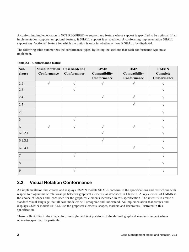
A conforming implementation is NOT REQUIRED to support any feature whose support is specified to be optional. If an implementation supports an optional feature, it SHALL support it as specified. A conforming implementation SHALL support any “optional” feature for which the option is only in whether or how it SHALL be displayed.
The following table summarizes the conformance types, by listing the sections that each conformance type must implement.
2.2 Visual Notation Conformance
An implementation that creates and displays CMMN models SHALL conform to the specifications and restrictions with respect to diagrammatic relationships between graphical elements, as described in Clause 6. A key element of CMMN is the choice of shapes and icons used for the graphical elements identified in this specification. The intent is to create a standard visual language that all case modelers will recognize and understand. An implementation that creates and displays CMMN models SHALL use the graphical elements, shapes, markers and decorators illustrated in this specification.
There is flexibility in the size, color, line style, and text positions of the defined graphical elements, except where otherwise specified. In particular:
Table 2.1 - Conformance Matrix
Sub clause
Visual Notation Conformance
Case Modeling Conformance
BPMN Compatibility Conformance
DMN Compatibility Conformance
CMMN Complete
Conformance
2.2 √ √ √ √ √2.3 √ √
2.4 √ √ √
2.5 √ √
2.6 √
5 √ √
6 √ √ √ √ √6.8.2.1 √ √
6.8.3.1 √ √
6.8.4.1 √ √
7 √ √
8 √
9 √ √
2 Case Management Model and Notation, v1.1
• CMMN elements MAY have labels (e.g., its name and/or other attributes) placed inside the shape, or above or below the shape, in any direction or location, depending on the preference of the modeler or modeling tool vendor.
• The fills that are used for the graphical elements MAY be white or clear. The notation MAY be extended to use other fill colors to suit the purpose of the modeler or tool (e.g., to highlight the value of an object attribute).
• Graphical elements, shapes, and decorators MAY be of any size that suits the purposes of the modeler or modeling tool.
• The lines that are used to draw the graphical elements MAY be black.
• The notation MAY be extended to use other line colors to suit the purpose of the modeler or tool (e.g., to highlight the value of an object attribute).
• The notation MAY be extended to use other line styles to suit the purpose of the modeler or tool (e.g., to highlight the value of an object attribute) with the condition that the line style MUST NOT conflict with any current CMMN or BPMN defined line style.
The following extensions to a CMMN model are permitted:
• New decorators or indicators MAY be added to the specified graphical elements. These decorators or indicators could be used to highlight a specific attribute of a CMMN element or to represent a new subtype of the corresponding concept.
• A new shape representing a kind of Case File Item or Plan Item MAY be added to a model, but the new Case File Item or Plan Item shape SHALL NOT conflict with the shape specified for any other CMMN or BPMN element or decorator.
• Graphical elements MAY be colored, and the coloring MAY have specified semantics that extend the information conveyed by the element as specified in this standard.
• The line style of a graphical element MAY be changed, but that change SHALL NOT conflict with any other line style REQUIRED by this specification or BPMN.
• An extension SHALL NOT change the specified shape of a defined graphical element or decorator. (e.g., changing a square into a triangle, or changing rounded corners into squared corners, etc.).
This compliance point is intended to be used by entry-level CMMN tools.
2.3 Case Modeling Conformance
The implementation claiming conformance to the Case Modeling Conformance SHALL comply with all of the requirements set forth in Clauses 5, 6, and 8; and it should be conformant with the Visual Notation Conformance in 2.2. A tool claiming Modeling Conformance MUST fully support the underlying metamodel in Clause 5, and MUST fully support the visual notation in Clause 6. Conformant implementations MUST fully support and interpret the exchange format specified in Clause 7.
This compliance point is intended to be used by modeling only tools.
2.4 BPMN Compatibility Conformance
The implementation claiming conformance to the BPMN Compatibility Conformance SHALL comply with all of the optional BPMN compatibility requirements set forth in 6.8.2.1 and 6.8.3.1, and should be conformant with the Visual Notation Conformance in 2.2. The optional BPMN compatibility requirements set forth in 6.8.2.1 and 6.8.3.1 are
Case Management Model and Notation, v1.1 3
considered required to claim conformance to the BPMN Compatibility Conformance. A BPMN Compatibility Conformance implementation is NOT REQUIRED to be conformant to the Case Modeling Conformance or to the CMMN Complete Conformance.
This compliance point is intended to be used by tools supporting both BPMN and CMMN.
2.5 DMN Compatibility Conformance
The implementation claiming conformance to the DMN Compatibility Conformance SHALL comply with all of the original DMN compatibility requirements set forth in 6.8.4.1. The optional DMN compatibility requirements set forth in 6.8.4.1 are considered required to claim conformance to the DMN Compatibility Conformance. A DMN Compatibility Conformance implementation is NOT REQUIRED to be conformant to the Case Modeling Conformance or to the CMMN Complete Conformance. This compliance point is intended to be used by tools supporting both DMN and CMMN.
2.6 CMMN Complete Conformance
The implementation claiming conformance to the CMMN Complete Conformance SHALL comply with all of the requirements set forth in Clauses 5, 6, 7 and 8; and it should be conformant with the Visual Notation Conformance in 2.2. A tool claiming CMMN Complete Conformance MUST fully support and interpret the underlying metamodel in Clause 5. Conformant implementations MUST fully support the visual notation in Clause 6. Conformant implementations MUST fully support and interpret the execution semantics and life-cycle specified in Clause 7, and it MUST fully support and interpret the exchange formats in Clause 8.
This compliance point is intended to be uses by tools supporting CMMN modeling and execution.
3 References
The following normative documents contain provisions which, through reference in this text, constitute provisions of this specification. For dated references, subsequent amendments to, or revisions of, any of these publications do not apply.
3.1 Normative References
RFC-2119
• “Key words for use in RFCs to Indicate Requirement Levels, S. Bradner, IETF RFC 2119, March 1997 http://www.ietf.org/rfc/rfc2119.txt
• Diagram Definition (DD) 1.1 Specification. http://www.omg.org/spec/DD/1.1/
3.2 Non-normative References
Aalst, W.M.P. van der, Weske, M.: Case Handling: a new paradigm for business process support. Data & Knowledge Engineering. 53(2). 129-162, 2005
Business Process Model and Notation (BPMN) Version 2.0, OMG, January 2011, http://www.omg.org/spec/BPMN/2.0/PDF/
4 Case Management Model and Notation, v1.1
Content Management Interoperability (CMIS). Florian Muller, Ryan McVeigh, Jens Hubel, eds., OASIS. 23 May 2013. http://docs.oasis-open.org/cmis/CMIS/v1.1/os/CMIS-v1.1-os.html
Davenport, Th. H. and Nohria, N., Case Management and the Integration of Labor, Sloan Management Review, 1994.
Davenport, Th. H, Thinking for a Living: How to Get Better Performance and Results from Knowledge Workers, HarvardBusinessSchool Press, 2005.
DMN, Decision Model and Notation. http://www.omg.org/spec/DMN/
Hull, R., Damaggio, E., Fournier, F., Gupta, M., Heath III, F.T., Hobson, S., Linehan, M., Maradugu, S., Nigam, A., Sukaviriya, P., and Vaculin, R., Introducing the Guard-Stage-Milestone Approach for Specifying Business Entity Lifecycles. Proceedings of the 7th International conference on Web Services and Formal Methods (WS-FM 2010). Bravetti, M., and Bultan, T. (eds.). Springer-Verlag, Berling, Heidelberg, 1-24. 2010.
Hull, R. et. al., Business artifacts with guard-stage-milestone lifecycles: Managing artifact interactions with conditions and events. Proceedings of the 5th ACM Intl. Conf. on Distributed Event-based Systems (DEBS), pages 51-62, New York, NY, USA, 2011.
Man, H. de, Case Management: A Review of Modeling Approaches, BPTrends, January 2009. [http://www.bptrends.com/publicationfiles/01-09-ART-%20Case%20Management-1-DeMan.%20doc--final.pdf]
XML Schema Part 2: Datatypes, Paul V. Biron and Ashol Malhotra, eds., W3C, 28 October 2004. http://www.w3.org/TR/xmlschema-2/
XML Path Language (XPath) 1.0. James Clark and Steve DeRose, eds., W3C, 16 November 1999. http://www.w3.org/TR/xpath
4 Additional Information
4.1 General Concept
A Case is a proceeding that involves actions taken regarding a subject in a particular situation to achieve a desired outcome. Traditional examples come from the legal and medical worlds, where a legal Case involves the application of the law to a subject in a certain fact situation, and a medical Case involves the care of a patient in the context of a medical history and current medical problems. The subject of a Case may be a person, a legal action, a business transaction, or some other focal point around which actions are taken to achieve an objective. The situation commonly includes data that inform and drive the actions taken in a Case.
Any individual Case may be resolved in a completely ad-hoc manner, but as experience grows in resolving similar Cases over time, a set of common practices and responses can be defined for managing Cases in a more rigorous and repeatable manner. This becomes the practice of Case management, around which software products have emerged to assist Case Workers whose job is to process and resolve Cases.
Case management is often directed by a human - a Case manager or a team of Case workers - with minimal predefined encoding of the work to be performed. A Case may not have a single, designated Case manager, but may collaboratively engage different participants as required to make decisions or perform certain Tasks.
Case Management Model and Notation, v1.1 5
Planning at run-time is a fundamental characteristic of Case management. Case management requires modeling and notation which can express the essential flexibility that human Case workers, especially knowledge workers, require for run-time planning for the selection of Tasks for a Case, run-time ordering of the sequence in which the Tasks are executed, and ad-hoc collaboration with other knowledge workers on the Tasks (see De Man, January 2009).
Case management planning is typically concerned with determination of which Tasks are applicable, or which follow-up Tasks are required, given the state of the Case. Decisions may be triggered by events or new facts that continuously emerge during the course of the Case, such as the receipt of new documents, completion of certain Tasks, or achieving certain Milestones. Individual Tasks that are planned and executed in the context of the Case might be predefined procedural Processes in themselves, but the overall Case cannot be orchestrated by a predefined sequence of Tasks.
Representation of the circumstances and the decision factors in a Case model requires references to data about the subject of the Case. The collection of data about the Case is often described as a CaseFile. Documents and other unstructured or structured data about a Case are captured and referenced in the CaseFile for decision-making by Case workers.
Modeling of constraints and guidance on the actions to be taken in a Case requires the specification of rules that reference the data in the CaseFile. A Case model may specify constraints on run-time state transitions as well as constraints on actions, and recommendations for actions, that are dependent on the run-time state of the Case. Even though this specification is focused on modeling and notation, not run-time Case management per se, execution semantics is important for modeling of constraints and rules that depend on run-time state. To that end, execution semantics defined in this specification -- describing how EventListeners, Stages, Tasks, and Milestones affect each other and the state of the Case during the run-time management of a Case -- have been influenced by recent research into business artifacts and the guard-stage-milestone formalism (see Hull 2010).
Cases are directed not just by explicit knowledge about the particular Case and its context represented in the CaseFile, but also by explicit knowledge encoded as rules by business analysts, the tacit knowledge of human participants, and tacit knowledge from the organization or community in which participants are members.
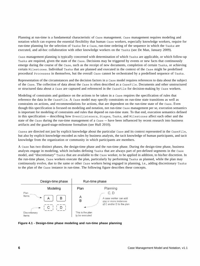
A Case has two distinct phases, the design-time phase and the run-time phase. During the design-time phase, business analysts engage in modeling, which includes defining Tasks that are always part of pre-defined segments in the Case model, and “discretionary” Tasks that are available to the Case worker, to be applied in addition, to his/her discretion. In the run-time phase, Case workers execute the plan, particularly by performing Tasks as planned, while the plan may continuously evolve, due to the same or other Case workers being engaged in planning, i.e., adding discretionary Tasks to the plan of the Case instance in run-time. The following figure describes these concepts.
Figure 4.1 - Design-time phase modeling and run-time phase planning
6 Case Management Model and Notation, v1.1
4.2 Target Users
Business analysts are the anticipated users of Case management tools for capturing and formalizing repeatable patterns of common Tasks, EventListeners, and Milestones into a Case model. A new Case model may be defined as entirely at the discretion of human participants initially, but it should be expected to evolve as repeatable patterns and best practices emerge. Patterns and outcomes from execution of the Case model can be incorporated iteratively by business analysts into the Case model, in the form of improved rules and more predictable patterns of Tasks, in order to make Case management more repeatable and improve outcomes over time.
4.3 Interoperability
In the context of Case management, this specification defines a meta-model (that is, a model for defining models), a notation for expressing Case models, and an XML Model for Interchange (XMI) and XML-Schema for exchanging Case models among different Case management vendors’ environments and tools. The meta-model can be used by Case management definition tools to define functions and features that a business analyst could use to define a Case model for a particular type of Case, such as invoice discrepancy handling. The notation is intended for use by those tools to express the model graphically.
This specification enables portability of Case models, so that users can take a model defined in one vendor’s environment and use it in another vendor’s environment. The CMMN XMI and/or XML-Schema are intended for importing and exporting Case models among different Case management vendors’ environments and tools.
A Case model is intended to be used by a run-time Case management product to guide and assist a knowledge worker in the handling of a particular instance of a Case, for example a particular invoice discrepancy. The meta-model and notation are used to express a case model in a common notation for a particular type of Case, and the resulting model can subsequently be instantiated for the handling of a particular instance of a Case.
4.4 Submitting and Supporting Organizations
The following companies are formal submitting members of OMG:
• BizAgi Limited
• Cordys Nederland BV
• International Business Machines Corporation
• Oracle Incorporated
• SAP AG
• Kofax plc
The following organizations have contributed to the development of this specification but are not formal submitters:
• Agile Enterprise Design, LLC
• Stiftelsen SINTEF
• TIBCO Software
• Trisotech
Case Management Model and Notation, v1.1 7
The following persons were members of the core teams that contributed to the content specification: Alan Babich, Henk de Man, Heidi Buelow, Bill Carpenter, Martin Chapman, Fred Cummins, Brian Elvesæter, Denis Gagne, Rick Hull, Dave Ings, Oliver Kieselbach, Matthias Kloppmann, Mike Marin, Greg Melahn, Paul O'Neill, Ralf Mueller, Ravi Rangaswamy, Jesus Sanchez, Arvind Srinivasan, Allen Takatsuka, Ivana Trickovic, Ganesh Vaideeswaran, Paul Vincent.
In addition, the following persons contributed valuable ideas and feedback that improved the content and the quality of this specification: Jay Brown, Melanie Gauthier, Thomas Hildebrandt, Knut Hinkelmann, Jana Koehler, Juergen Kress, Mathias Kurz, Robert Lario, Scott Malabarba, Lauren Mayes, Simon Ringuette, Danilo Schmiedel, Roman Smirnov, Paul Winsbert, and Torsten Winterberg.
4.5 IPR and Patents
The authors intend to contribute this work to OMG on a RF on RAND basis.
4.6 Guide to the Specification
This specification is organized into clauses. Those clauses that are normative are indicated as such.
8 Case Management Model and Notation, v1.1
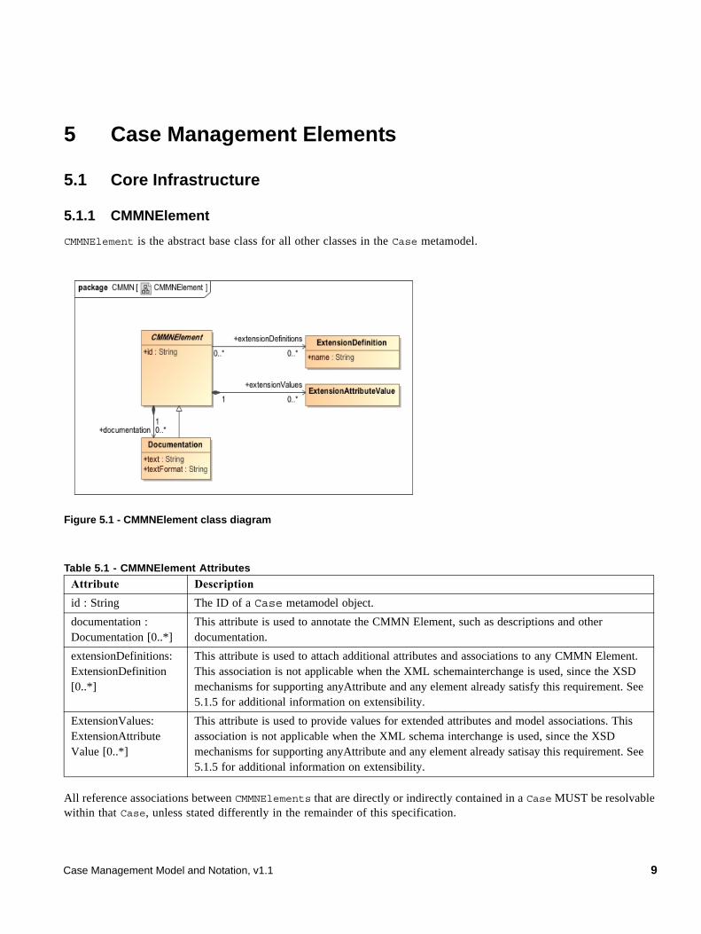
5 Case Management Elements
5.1 Core Infrastructure
5.1.1 CMMNElement
CMMNElement is the abstract base class for all other classes in the Case metamodel.
Figure 5.1 - CMMNElement class diagram
All reference associations between CMMNElements that are directly or indirectly contained in a Case MUST be resolvable within that Case, unless stated differently in the remainder of this specification.
Table 5.1 - CMMNElement Attributes
Attribute Description
id : String The ID of a Case metamodel object.
documentation : Documentation [0..*]
This attribute is used to annotate the CMMN Element, such as descriptions and other documentation.
extensionDefinitions: ExtensionDefinition [0..*]
This attribute is used to attach additional attributes and associations to any CMMN Element. This association is not applicable when the XML schemainterchange is used, since the XSD mechanisms for supporting anyAttribute and any element already satisfy this requirement. See 5.1.5 for additional information on extensibility.
ExtensionValues: ExtensionAttribute Value [0..*]
This attribute is used to provide values for extended attributes and model associations. This association is not applicable when the XML schema interchange is used, since the XSD mechanisms for supporting anyAttribute and any element already satisay this requirement. See 5.1.5 for additional information on extensibility.
Case Management Model and Notation, v1.1 9
5.1.1.1 Documentation
All CMMN elements that inherit from class CMMNElement will have the capability, through Documentation element, to have one (1) or more text descriptions of that element.
The Documentation element inherits the attributes and model associations of CMMNElement and has the following attributes.
5.1.2 Definitions
The Definitions class is the outermost containing object for all CMMNElements. It defines the scope of visibility and the namespace for all contained elements. The interchange of CMMN files will always be through one or more Definitions.
Attribute Description
text : String This attribute is used to capture the text descriptions of a CMMN element.
textFormat: String This attribute identifies the format of the text. It MUST follow the mime-type format. The default is “text/plain.”
10 Case Management Model and Notation, v1.1
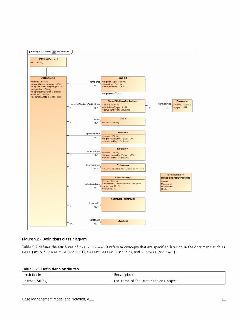
Figure 5.2 - Definitions class diagram
Table 5.2 defines the attributes of Definitions. It refers to concepts that are specified later on in the document, such as Case (see 5.2), CaseFile (see 5.3.1), CaseFileItem (see 5.3.2), and Process (see 5.4.8).
Table 5.2 - Definitions attributes
Attribute Description
name : String The name of the Definitions object.
Case Management Model and Notation, v1.1 11
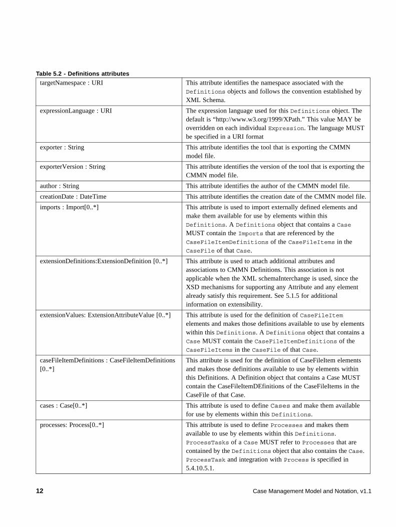
targetNamespace : URI This attribute identifies the namespace associated with the Definitions objects and follows the convention established by XML Schema.
expressionLanguage : URI The expression language used for this Definitions object. The default is “http://www.w3.org/1999/XPath.” This value MAY be overridden on each individual Expression. The language MUST be specified in a URI format
exporter : String This attribute identifies the tool that is exporting the CMMN model file.
exporterVersion : String This attribute identifies the version of the tool that is exporting the CMMN model file.
author : String This attribute identifies the author of the CMMN model file.
creationDate : DateTime This attribute identifies the creation date of the CMMN model file.
imports : Import[0..*] This attribute is used to import externally defined elements and make them available for use by elements within this Definitions. A Definitions object that contains a Case MUST contain the Imports that are referenced by the CaseFileItemDefinitions of the CaseFileItems in the CaseFile of that Case.
extensionDefinitions:ExtensionDefinition [0..*] This attribute is used to attach additional attributes and associations to CMMN Definitions. This association is not applicable when the XML schemaInterchange is used, since the XSD mechanisms for supporting any Attribute and any element already satisfy this requirement. See 5.1.5 for additional information on extensibility.
extensionValues: ExtensionAttributeValue [0..*] This attribute is used for the definition of CaseFileItem elements and makes those definitions available to use by elements within this Definitions. A Definitions object that contains a Case MUST contain the CaseFileItemDefinitions of the CaseFileItems in the CaseFile of that Case.
caseFileItemDefinitions : CaseFileItemDefinitions [0..*]
This attribute is used for the definition of CaseFileItem elements and makes those definitions available to use by elements within this Definitions. A Definition object that contains a Case MUST contain the CaseFileItemDEfinitions of the CaseFileItems in the CaseFile of that Case.
cases : Case[0..*] This attribute is used to define Cases and make them available for use by elements within this Definitions.
processes: Process[0..*] This attribute is used to define Processes and makes them available to use by elements within this Definitions. ProcessTasks of a Case MUST refer to Processes that are contained by the Definitions object that also contains the Case. ProcessTask and integration with Process is specified in 5.4.10.5.1.
Table 5.2 - Definitions attributes
12 Case Management Model and Notation, v1.1
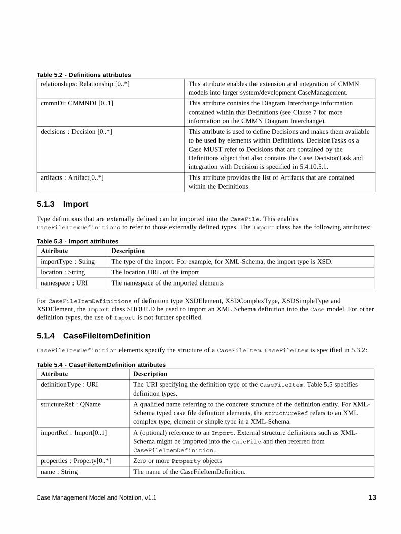
5.1.3 Import
Type definitions that are externally defined can be imported into the CaseFile. This enables CaseFileItemDefinitions to refer to those externally defined types. The Import class has the following attributes:
For CaseFileItemDefinitions of definition type XSDElement, XSDComplexType, XSDSimpleType and XSDElement, the Import class SHOULD be used to import an XML Schema definition into the Case model. For other definition types, the use of Import is not further specified.
5.1.4 CaseFileItemDefinition
CaseFileItemDefinition elements specify the structure of a CaseFileItem. CaseFileItem is specified in 5.3.2:
relationships: Relationship [0..*] This attribute enables the extension and integration of CMMN models into larger system/development CaseManagement.
cmmnDi: CMMNDI [0..1] This attribute contains the Diagram Interchange information contained within this Definitions (see Clause 7 for more information on the CMMN Diagram Interchange).
decisions : Decision [0..*] This attribute is used to define Decisions and makes them available to be used by elements within Definitions. DecisionTasks os a Case MUST refer to Decisions that are contained by the Definitions object that also contains the Case DecisionTask and integration with Decision is specified in 5.4.10.5.1.
artifacts : Artifact[0..*] This attribute provides the list of Artifacts that are contained within the Definitions.
Table 5.3 - Import attributes
Attribute Description
importType : String The type of the import. For example, for XML-Schema, the import type is XSD.
location : String The location URL of the import
namespace : URI The namespace of the imported elements
Table 5.4 - CaseFileItemDefinition attributes
Attribute Description
definitionType : URI The URI specifying the definition type of the CaseFileItem. Table 5.5 specifies definition types.
structureRef : QName A qualified name referring to the concrete structure of the definition entity. For XML-Schema typed case file definition elements, the structureRef refers to an XML complex type, element or simple type in a XML-Schema.
importRef : Import[0..1] A (optional) reference to an Import. External structure definitions such as XML-Schema might be imported into the CaseFile and then referred from CaseFileItemDefinition.
properties : Property[0..*] Zero or more Property objects
name : String The name of the CaseFileItemDefinition.
Table 5.2 - Definitions attributes
Case Management Model and Notation, v1.1 13
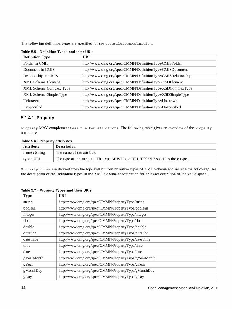
The following definition types are specified for the CaseFileItemDefinition:
5.1.4.1 Property
Property MAY complement CaseFileItemDefinitions. The following table gives an overview of the Property attributes:
Property types are derived from the top-level built-in primitive types of XML Schema and include the following, see the description of the individual types in the XML Schema specification for an exact definition of the value space.
Table 5.5 - Definition Types and their URIs
Definition Type URI
Folder in CMIS http://www.omg.org/spec/CMMN/DefinitionType/CMISFolder
Document in CMIS http://www.omg.org/spec/CMMN/DefinitionType/CMISDocument
Relationship in CMIS http://www.omg.org/spec/CMMN/DefinitionType/CMISRelationship
XML-Schema Element http://www.omg.org/spec/CMMN/DefinitionType/XSDElement
XML Schema Complex Type http://www.omg.org/spec/CMMN/DefinitionType/XSDComplexType
XML Schema Simple Type http://www.omg.org/spec/CMMN/DefinitionType/XSDSimpleType
Unknown http://www.omg.org/spec/CMMN/DefinitionType/Unknown
Unspecified http://www.omg.org/spec/CMMN/DefinitionType/Unspecified
Table 5.6 - Property attributes
Attribute Description
name : String The name of the attribute
type : URI The type of the attribute. The type MUST be a URI. Table 5.7 specifies these types.
Table 5.7 - Property Types and their URIs
Type URI
string http://www.omg.org/spec/CMMN/PropertyType/string
boolean http://www.omg.org/spec/CMMN/PropertyType/boolean
integer http://www.omg.org/spec/CMMN/PropertyType/integer
float http://www.omg.org/spec/CMMN/PropertyType/float
double http://www.omg.org/spec/CMMN/PropertyType/double
duration http://www.omg.org/spec/CMMN/PropertyType/duration
dateTime http://www.omg.org/spec/CMMN/PropertyType/dateTime
time http://www.omg.org/spec/CMMN/PropertyType/time
date http://www.omg.org/spec/CMMN/PropertyType/date
gYearMonth http://www.omg.org/spec/CMMN/PropertyType/gYearMonth
gYear http://www.omg.org/spec/CMMN/PropertyType/gYear
gMonthDay http://www.omg.org/spec/CMMN/PropertyType/gMonthDay
gDay http://www.omg.org/spec/CMMN/PropertyType/gDay
14 Case Management Model and Notation, v1.1
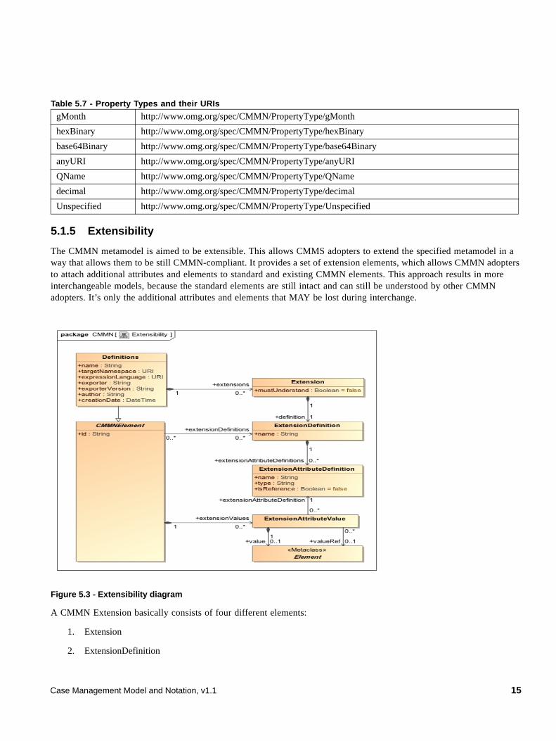
5.1.5 Extensibility
The CMMN metamodel is aimed to be extensible. This allows CMMS adopters to extend the specified metamodel in a way that allows them to be still CMMN-compliant. It provides a set of extension elements, which allows CMMN adopters to attach additional attributes and elements to standard and existing CMMN elements. This approach results in more interchangeable models, because the standard elements are still intact and can still be understood by other CMMN adopters. It’s only the additional attributes and elements that MAY be lost during interchange.
Figure 5.3 - Extensibility diagram
A CMMN Extension basically consists of four different elements:
1. Extension
2. ExtensionDefinition
gMonth http://www.omg.org/spec/CMMN/PropertyType/gMonth
hexBinary http://www.omg.org/spec/CMMN/PropertyType/hexBinary
base64Binary http://www.omg.org/spec/CMMN/PropertyType/base64Binary
anyURI http://www.omg.org/spec/CMMN/PropertyType/anyURI
QName http://www.omg.org/spec/CMMN/PropertyType/QName
decimal http://www.omg.org/spec/CMMN/PropertyType/decimal
Unspecified http://www.omg.org/spec/CMMN/PropertyType/Unspecified
Table 5.7 - Property Types and their URIs
Case Management Model and Notation, v1.1 15
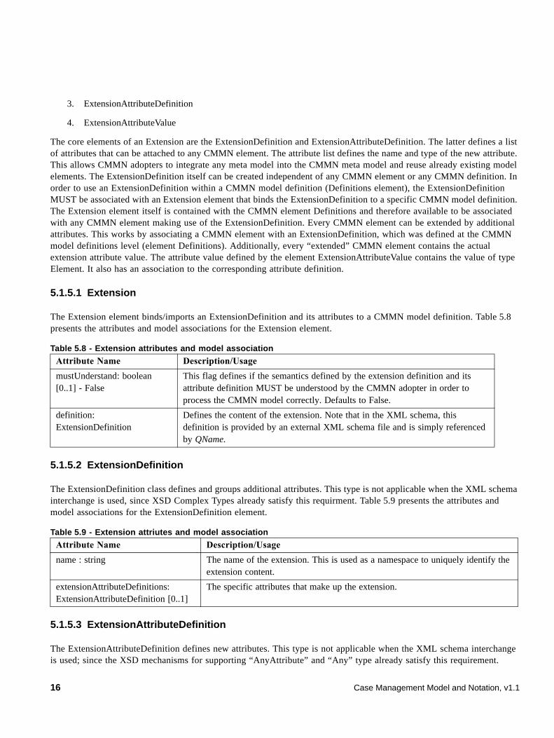
3. ExtensionAttributeDefinition
4. ExtensionAttributeValue
The core elements of an Extension are the ExtensionDefinition and ExtensionAttributeDefinition. The latter defines a list of attributes that can be attached to any CMMN element. The attribute list defines the name and type of the new attribute. This allows CMMN adopters to integrate any meta model into the CMMN meta model and reuse already existing model elements. The ExtensionDefinition itself can be created independent of any CMMN element or any CMMN definition. In order to use an ExtensionDefinition within a CMMN model definition (Definitions element), the ExtensionDefinition MUST be associated with an Extension element that binds the ExtensionDefinition to a specific CMMN model definition. The Extension element itself is contained with the CMMN element Definitions and therefore available to be associated with any CMMN element making use of the ExtensionDefinition. Every CMMN element can be extended by additional attributes. This works by associating a CMMN element with an ExtensionDefinition, which was defined at the CMMN model definitions level (element Definitions). Additionally, every “extended” CMMN element contains the actual extension attribute value. The attribute value defined by the element ExtensionAttributeValue contains the value of type Element. It also has an association to the corresponding attribute definition.
5.1.5.1 Extension
The Extension element binds/imports an ExtensionDefinition and its attributes to a CMMN model definition. Table 5.8 presents the attributes and model associations for the Extension element.
5.1.5.2 ExtensionDefinition
The ExtensionDefinition class defines and groups additional attributes. This type is not applicable when the XML schema interchange is used, since XSD Complex Types already satisfy this requirment. Table 5.9 presents the attributes and model associations for the ExtensionDefinition element.
5.1.5.3 ExtensionAttributeDefinition
The ExtensionAttributeDefinition defines new attributes. This type is not applicable when the XML schema interchange is used; since the XSD mechanisms for supporting “AnyAttribute” and “Any” type already satisfy this requirement.
Table 5.8 - Extension attributes and model association
Attribute Name Description/Usage
mustUnderstand: boolean [0..1] - False
This flag defines if the semantics defined by the extension definition and its attribute definition MUST be understood by the CMMN adopter in order to process the CMMN model correctly. Defaults to False.
definition: ExtensionDefinition
Defines the content of the extension. Note that in the XML schema, this definition is provided by an external XML schema file and is simply referenced by QName.
Table 5.9 - Extension attriutes and model association
Attribute Name Description/Usage
name : string The name of the extension. This is used as a namespace to uniquely identify the extension content.
extensionAttributeDefinitions: ExtensionAttributeDefinition [0..1]
The specific attributes that make up the extension.
16 Case Management Model and Notation, v1.1
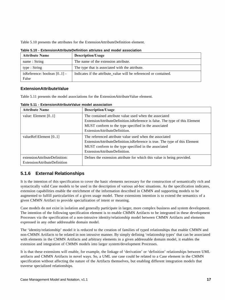
Table 5.10 presents the attributes for the ExtensionAttributeDefinition element.
ExtensionAttributeValue
Table 5.11 presents the model associations for the ExtensionAttributeValue element.
5.1.6 External Relationships
It is the intention of this specification to cover the basic elements necessary for the construction of semantically rich and syntactically valid Case models to be used in the description of various ad-hoc situations. As the specification indicates, extension capabilities enable the enrichment of the information described in CMMN and supporting models to be augmented to fulfill particularities of a given usage model. These extensions intention is to extend the semantics of a given CMMN Artifact to provide specialization of intent or meaning.
Case models do not exist in isolation and generally participate in larger, more complex business and system development. The intention of the following specification element is to enable CMMN Artifacts to be integrated in these development Processes via the specification of a non-intrusive identity/relationship model between CMMN Artifacts and elements expressed in any other addressable domain model.
The ‘identity/relationship’ model it is reduced to the creation of families of typed relationships that enable CMMN and non-CMMN Artifacts to be related in non intrusive manner. By simply defining ‘relationship types’ that can be associated with elements in the CMMN Artifacts and arbitrary elements in a given addressable domain model, it enables the extension and integration of CMMN models into larger system/development Processes.
It is that these extensions will enable, for example, the linkage of ‘derivation’ or ‘definition’ relationships between UML artifacts and CMMN Artifacts in novel ways. So, a UML use case could be related to a Case element in the CMMN specification without affecting the nature of the Artifacts themselves, but enabling different integration models that traverse specialized relationships.
Table 5.10 - ExtensionAttributeDefinition attriutes and model association
Attribute Name Description/Usage
name : String The name of the extension attribute.
type : String The type that is associated with the attribute.
isReference: boolean [0..1] - False
Indicates if the attribute_value will be referenced or contained.
Table 5.11 - ExtensionAttributeValue model association
Attribute Name Description/Usage
value: Element [0..1] The contained attribute value used when the associated ExtensionAttributeDefinition.isReference is false. The type of this Element MUST conform to the type specified in the associated ExtensionAttributeDefinition.
valueRef:Element [0..1] The referenced attribute value used when the associated ExtensionAttributeDefinition.isReference is true. The type of this Element MUST conform to the type specified in the associated ExtensionAttributeDefinition.
extensionAttributeDefinition: ExtensionAttributeDefinition
Defnes the extension attribute for which this value is being provided.
Case Management Model and Notation, v1.1 17
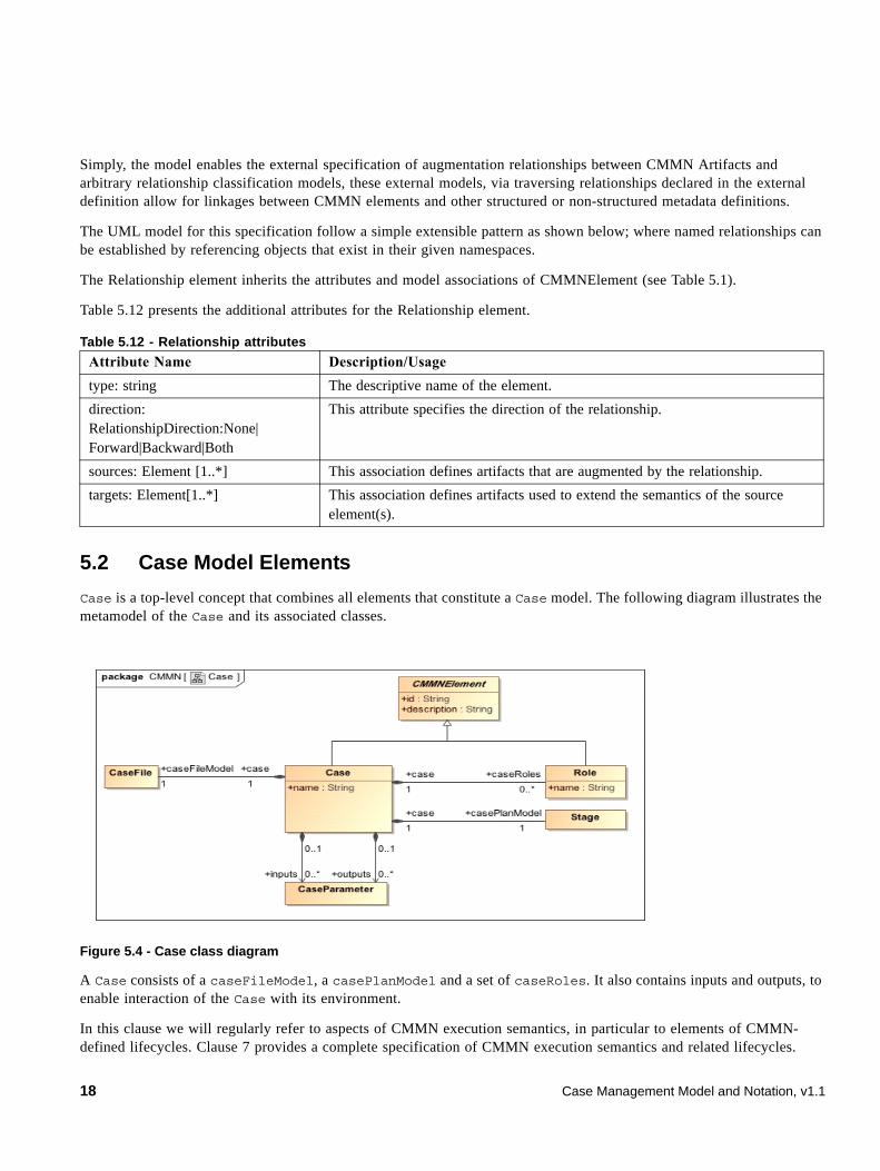
Simply, the model enables the external specification of augmentation relationships between CMMN Artifacts and arbitrary relationship classification models, these external models, via traversing relationships declared in the external definition allow for linkages between CMMN elements and other structured or non-structured metadata definitions.
The UML model for this specification follow a simple extensible pattern as shown below; where named relationships can be established by referencing objects that exist in their given namespaces.
The Relationship element inherits the attributes and model associations of CMMNElement (see Table 5.1).
Table 5.12 presents the additional attributes for the Relationship element.
5.2 Case Model Elements
Case is a top-level concept that combines all elements that constitute a Case model. The following diagram illustrates the metamodel of the Case and its associated classes.
Figure 5.4 - Case class diagram
A Case consists of a caseFileModel, a casePlanModel and a set of caseRoles. It also contains inputs and outputs, to enable interaction of the Case with its environment.
In this clause we will regularly refer to aspects of CMMN execution semantics, in particular to elements of CMMN-defined lifecycles. Clause 7 provides a complete specification of CMMN execution semantics and related lifecycles.
Table 5.12 - Relationship attributes
Attribute Name Description/Usage
type: string The descriptive name of the element.
direction: RelationshipDirection:None| Forward|Backward|Both
This attribute specifies the direction of the relationship.
sources: Element [1..*] This association defines artifacts that are augmented by the relationship.
targets: Element[1..*] This association defines artifacts used to extend the semantics of the source element(s).
18 Case Management Model and Notation, v1.1
5.2.1 Case
The Case class inherits from the CMMNElement class and comprises of the following additional attributes:
5.2.2 Role
CaseRoles authorize case workers or teams of case workers to perform HumanTasks (specified in 5.4.10.4), plan based on DiscretionaryItems (specified in 5.4.9.2), and raise user events (by triggering UserEventListeners, as specified in 5.4.2.2).
Example Roles of a case might be:
• Doctor - A doctor Role may contain one or more participants that are allowed to perform HumanTasks, trigger UserEventListeners, or do planning that requires doctor skills.
• Patient - A Case may provide an interface for patients to do planning that may correspond to scheduling appointments, complete HumanTasks that may correspond to providing information about their health, etc. In a typical application, a Case may limit the patient Role to contain a single participant.
• Nurse - A nurse Role may represent one or more participants with the skills of a nurse care provider.
Assignment of Roles to participants, such as to individuals or teams, is not included in the scope of CMMN.
The Role class inherits from the CMMNElement class and comprises of the following additional attributes:
Table 5.13 - Case attributes
Attribute Description
name : String The name of the Case
caseRoles : Role[0..*] This attribute lists the Role objects associated with the Case. These Roles are specific to the Case, and are not known outside the context of the Case.
caseFileModel : CaseFile[1] One CaseFile object. Every Case MUST be associated with exactly one CaseFile. CaseFile is specified in 5.3.1.
casePlanModel : Stage[1] The plan model of the Case. Every Case MUST be associated with exactly one plan model. It is defined by association to Stage. Stage is specified in 5.4.8. As it will appear in that sub clause, Stage represents a recursive concept (Stages can be nested within other Stages), used as container of elements from which the plan of the case is constructed and can further evolve, and having a lifecycle that can be tracked in run-time. The “most outer” Stage is associated to the Case as its casePlanModel.
inputs : CaseParameter[0..*] Input Parameters of the Case. A Case might have input Parameters so that it can be called from outside, e.g., by other Cases. CaseParameters are specified in 5.4.10.3.
outputs : CaseParameter[0..*] Output Parameters of the Case. A Case might have output parameters so that it can return a result to e.g., a calling Case.
Case Management Model and Notation, v1.1 19
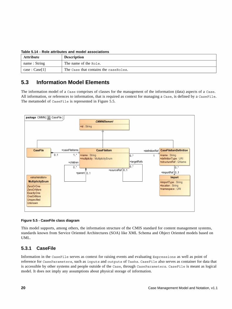
5.3 Information Model Elements
The information model of a Case comprises of classes for the management of the information (data) aspects of a Case. All information, or references to information, that is required as context for managing a Case, is defined by a CaseFile. The metamodel of CaseFile is represented in Figure 5.5.
Figure 5.5 - CaseFile class diagram
This model supports, among others, the information structure of the CMIS standard for content management systems, standards known from Service Oriented Architectures (SOA) like XML Schema and Object Oriented models based on UML.
5.3.1 CaseFile
Information in the CaseFile serves as context for raising events and evaluating Expressions as well as point of reference for CaseParameters, such as inputs and outputs of Tasks. CaseFile also serves as container for data that is accessible by other systems and people outside of the Case, through CaseParameters. CaseFile is meant as logical model. It does not imply any assumptions about physical storage of information.
Table 5.14 - Role attributes and model associations
Attribute Description
name : String The name of the Role.
case : Case[1] The Case that contains the caseRoles.
20 Case Management Model and Notation, v1.1
Every Case is associated with exactly one CaseFile. The Case information is represented by the CaseFile. It contains CaseFileItems that can be any type of data structure. In particular containment hierarchies and other content objects can be represented. The Case File is represented in the metamodel by the class CaseFile, which has the following attributes:
5.3.2 CaseFileItem
A CaseFile consists of CaseFileItems. A CaseFileItem may represent a piece of information of any nature, ranging from unstructured to structured, and from simple to complex, which information can be defined based on any information modeling “language.” A CaseFileItem can be anything from a folder or document stored in CMIS, an entire folder hierarchy referring or containing other CaseFileItems, or simply an XML document with a given structure. The structure, as well as the “language” (or format) to define the structure, is defined by the associated CaseFileItemDefinition (see 5.1.4). This may include the definition of properties (“metadata”) of a CaseFileItem. If the internal content of the CaseFileItem is known, an XML Schema, describing the CaseFileItem, may be imported.
CaseFileItems can be organized into arbitrary hierarchies of CaseFileItems either by containment or by reference. For containment hierarchies the associations children and parent are used whereas for reference hierarchies the associations targetRefs and sourceRef are used. For example, a folder hierarchy can be implemented by using a CaseFileItemDefinition.definitionType of CMISFolder, and using children and parent CaseFileItems as the folder structure. The resulting hierarchy can include metadata for each folder represented by the properties as defined by the associated CaseFileItemDefinition.
Case file items can be used to represent arbitrary content. For example, documents can be implemented by using CaseFileItemDefinition.definitionType of CMISDocument. There is no need to know the internals of those content objects, but if the internals of the object are known, the XML Schema can be defined by the Import class (see 5.1.3) of the CaseFileItemDefinition. The document or content object can include metadata as well, as represented by the properties as defined by the associated CaseFileItemDefinition.
The following attributes are defined for CaseFileItem:
Table 5.15 - CaseFile attributes and model associations
Attribute Description
caseFileItems : CaseFileItem[1..*] This attribute lists the CaseFileItems of a CaseFile. A CaseFile MUST contain at least one CaseFileItem.
Table 5.16 - CaseFileItem attributes
Attribute Description
name : String The name of the CaseFileItem.
multiplicity : MultiplicityEnum The multiplicity of the CaseFileItem. The multiplicity specifies the number of potential instances of this CaseFileItem in the context of a particular Case instance. For example: An auto-damage claim might require “4” photographs of tire profiles. An antecedent investigation might involve “zero or more” police reports.
definitionRef : CaseFileItemDefinition[1] A reference to the CaseFileItemDefinition. Every CaseFileItem MUST be associated to exactly one CaseFileItemDefinition.
Case Management Model and Notation, v1.1 21
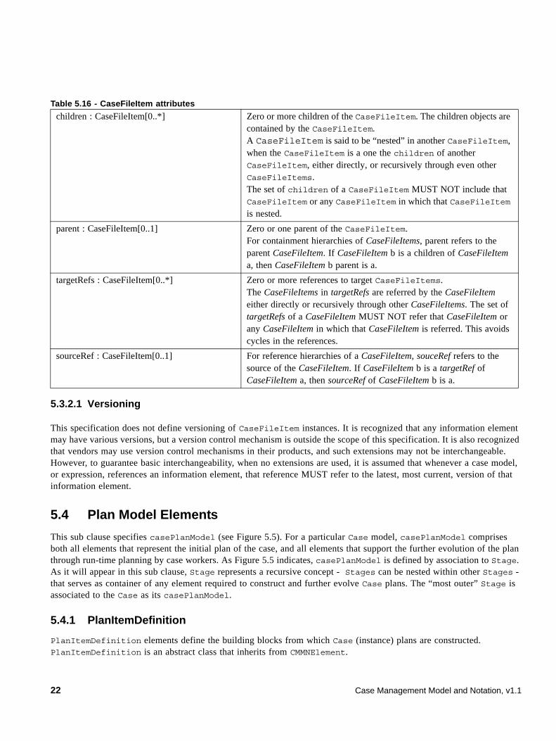
5.3.2.1 Versioning
This specification does not define versioning of CaseFileItem instances. It is recognized that any information element may have various versions, but a version control mechanism is outside the scope of this specification. It is also recognized that vendors may use version control mechanisms in their products, and such extensions may not be interchangeable. However, to guarantee basic interchangeability, when no extensions are used, it is assumed that whenever a case model, or expression, references an information element, that reference MUST refer to the latest, most current, version of that information element.
5.4 Plan Model Elements
This sub clause specifies casePlanModel (see Figure 5.5). For a particular Case model, casePlanModel comprises both all elements that represent the initial plan of the case, and all elements that support the further evolution of the plan through run-time planning by case workers. As Figure 5.5 indicates, casePlanModel is defined by association to Stage. As it will appear in this sub clause, Stage represents a recursive concept - Stages can be nested within other Stages - that serves as container of any element required to construct and further evolve Case plans. The “most outer” Stage is associated to the Case as its casePlanModel.
5.4.1 PlanItemDefinition
PlanItemDefinition elements define the building blocks from which Case (instance) plans are constructed. PlanItemDefinition is an abstract class that inherits from CMMNElement.
children : CaseFileItem[0..*] Zero or more children of the CaseFileItem. The children objects are contained by the CaseFileItem.A CaseFileItem is said to be “nested” in another CaseFileItem, when the CaseFileItem is a one the children of another CaseFileItem, either directly, or recursively through even other CaseFileItems.The set of children of a CaseFileItem MUST NOT include that CaseFileItem or any CaseFileItem in which that CaseFileItem is nested.
parent : CaseFileItem[0..1] Zero or one parent of the CaseFileItem. For containment hierarchies of CaseFileItems, parent refers to the parent CaseFileItem. If CaseFileItem b is a children of CaseFileItem a, then CaseFileItem b parent is a.
targetRefs : CaseFileItem[0..*] Zero or more references to target CaseFileItems. The CaseFileItems in targetRefs are referred by the CaseFileItem either directly or recursively through other CaseFileItems. The set of targetRefs of a CaseFileItem MUST NOT refer that CaseFileItem or any CaseFileItem in which that CaseFileItem is referred. This avoids cycles in the references.
sourceRef : CaseFileItem[0..1] For reference hierarchies of a CaseFileItem, souceRef refers to the source of the CaseFileItem. If CaseFileItem b is a targetRef of CaseFileItem a, then sourceRef of CaseFileItem b is a.
Table 5.16 - CaseFileItem attributes
22 Case Management Model and Notation, v1.1
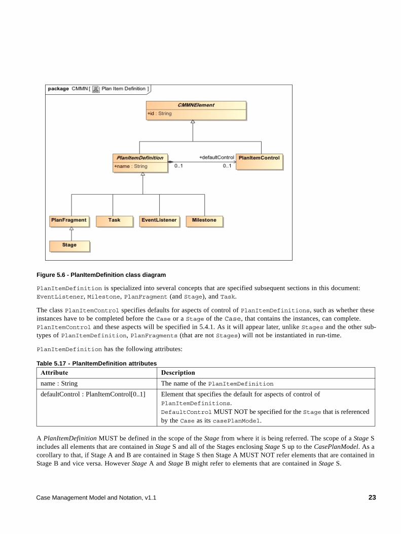
Figure 5.6 - PlanItemDefinition class diagram
PlanItemDefinition is specialized into several concepts that are specified subsequent sections in this document: EventListener, Milestone, PlanFragment (and Stage), and Task.
The class PlanItemControl specifies defaults for aspects of control of PlanItemDefinitions, such as whether these instances have to be completed before the Case or a Stage of the Case, that contains the instances, can complete. PlanItemControl and these aspects will be specified in 5.4.1. As it will appear later, unlike Stages and the other sub-types of PlanItemDefinition, PlanFragments (that are not Stages) will not be instantiated in run-time.
PlanItemDefinition has the following attributes:
A PlanItemDefinition MUST be defined in the scope of the Stage from where it is being referred. The scope of a Stage S includes all elements that are contained in Stage S and all of the Stages enclosing Stage S up to the CasePlanModel. As a corollary to that, if Stage A and B are contained in Stage S then Stage A MUST NOT refer elements that are contained in Stage B and vice versa. However Stage A and Stage B might refer to elements that are contained in Stage S.
Table 5.17 - PlanItemDefinition attributes
Attribute Description
name : String The name of the PlanItemDefinition
defaultControl : PlanItemControl[0..1] Element that specifies the default for aspects of control of PlanItemDefinitions.DefaultControl MUST NOT be specified for the Stage that is referenced by the Case as its casePlanModel.
Case Management Model and Notation, v1.1 23
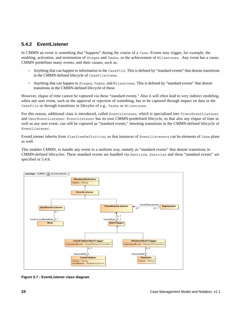
5.4.2 EventListener
In CMMN an event is something that “happens” during the course of a Case. Events may trigger, for example, the enabling, activation, and termination of Stages and Tasks, or the achievement of Milestones. Any event has a cause. CMMN predefines many events, and their causes, such as:
• Anything that can happen to information in the CaseFile. This is defined by “standard events” that denote transitions in the CMMN-defined lifecycle of CaseFileItems.
• Anything that can happen to Stages, Tasks, and Milestones. This is defined by “standard events” that denote transitions in the CMMN-defined lifecycle of these.
However, elapse of time cannot be captured via these “standard events.” Also it will often lead to very indirect modeling, when any user event, such as the approval or rejection of something, has to be captured through impact on data in the CaseFile or through transitions in lifecyles of e.g., Tasks or Milestones.
For this reason, additional class is introduced, called EventListener, which is specialized into TimerEventListener and UserEventListener. EventListener has its own CMMN-predefined lifecycle, so that also any elapse of time as well as any user event, can still be captured as “standard events,” denoting transitions in the CMMN-defined lifecycle of EventListener.
EventListener inherits from PlanItemDefinition, so that instances of EventListeners can be elements of Case plans as well.
This enables CMMN, to handle any event in a uniform way, namely as “standard events” that denote transitions in CMMN-defined lifecycles. These standard events are handled via Sentries. Sentries and these “standard events” are specified in 5.4.6.
Figure 5.7 - EventListener class diagram
24 Case Management Model and Notation, v1.1
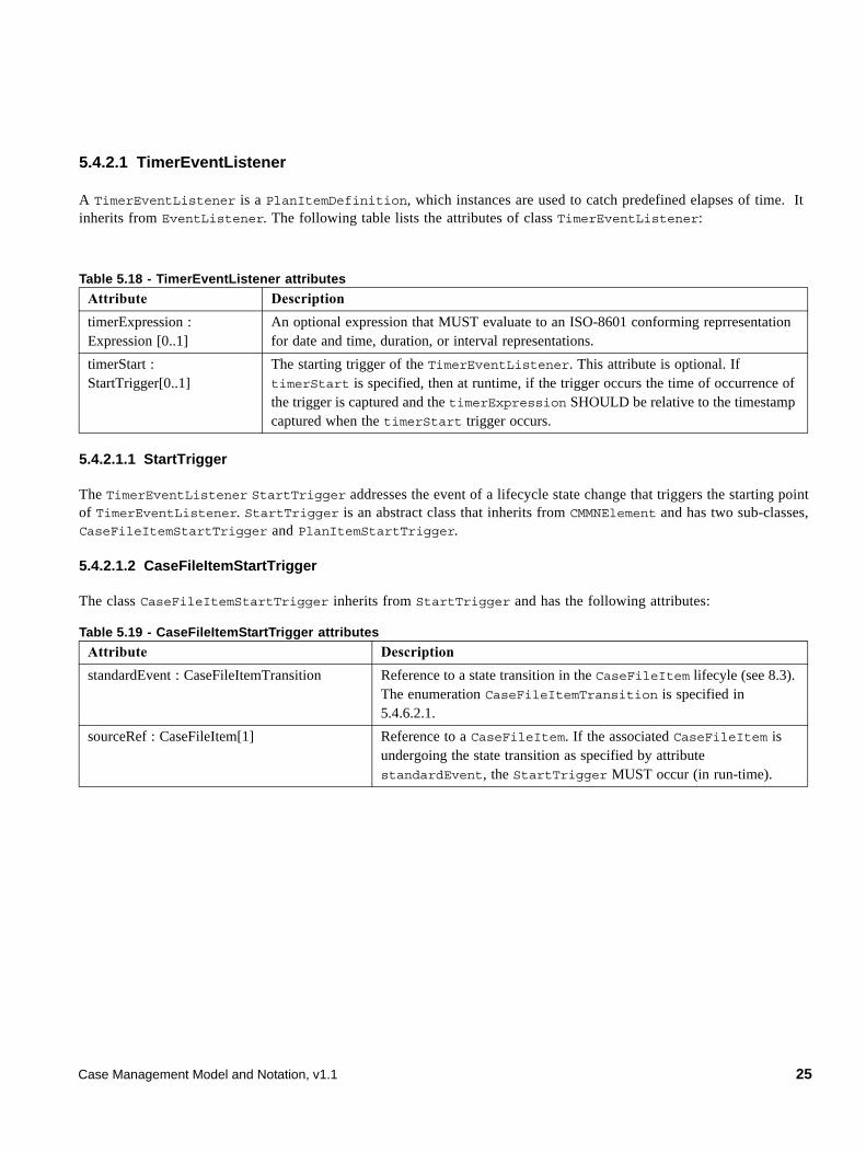
5.4.2.1 TimerEventListener
A TimerEventListener is a PlanItemDefinition, which instances are used to catch predefined elapses of time. It inherits from EventListener. The following table lists the attributes of class TimerEventListener:
5.4.2.1.1 StartTrigger
The TimerEventListener StartTrigger addresses the event of a lifecycle state change that triggers the starting point of TimerEventListener. StartTrigger is an abstract class that inherits from CMMNElement and has two sub-classes, CaseFileItemStartTrigger and PlanItemStartTrigger.
5.4.2.1.2 CaseFileItemStartTrigger
The class CaseFileItemStartTrigger inherits from StartTrigger and has the following attributes:
Table 5.18 - TimerEventListener attributes
Attribute Description
timerExpression : Expression [0..1]
An optional expression that MUST evaluate to an ISO-8601 conforming reprresentation for date and time, duration, or interval representations.
timerStart : StartTrigger[0..1]
The starting trigger of the TimerEventListener. This attribute is optional. If timerStart is specified, then at runtime, if the trigger occurs the time of occurrence of the trigger is captured and the timerExpression SHOULD be relative to the timestamp captured when the timerStart trigger occurs.
Table 5.19 - CaseFileItemStartTrigger attributes
Attribute Description
standardEvent : CaseFileItemTransition Reference to a state transition in the CaseFileItem lifecyle (see 8.3). The enumeration CaseFileItemTransition is specified in 5.4.6.2.1.
sourceRef : CaseFileItem[1] Reference to a CaseFileItem. If the associated CaseFileItem is undergoing the state transition as specified by attribute standardEvent, the StartTrigger MUST occur (in run-time).
Case Management Model and Notation, v1.1 25
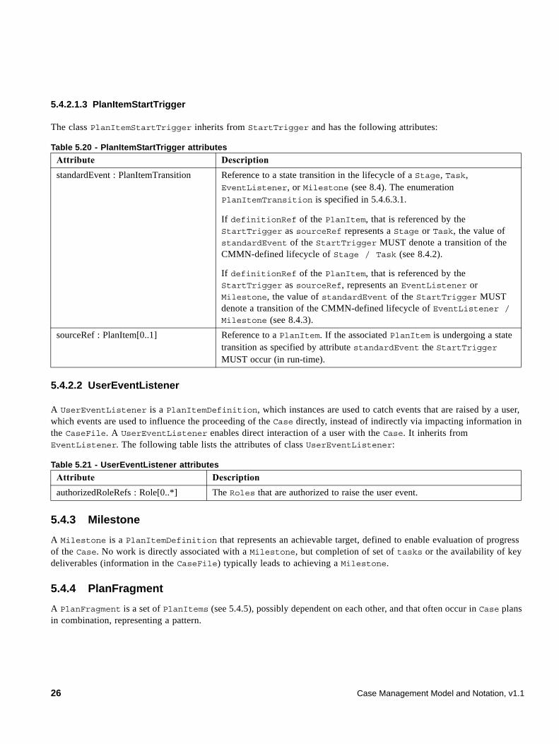
5.4.2.1.3 PlanItemStartTrigger
The class PlanItemStartTrigger inherits from StartTrigger and has the following attributes:
5.4.2.2 UserEventListener
A UserEventListener is a PlanItemDefinition, which instances are used to catch events that are raised by a user, which events are used to influence the proceeding of the Case directly, instead of indirectly via impacting information in the CaseFile. A UserEventListener enables direct interaction of a user with the Case. It inherits from EventListener. The following table lists the attributes of class UserEventListener:
5.4.3 Milestone
A Milestone is a PlanItemDefinition that represents an achievable target, defined to enable evaluation of progress of the Case. No work is directly associated with a Milestone, but completion of set of tasks or the availability of key deliverables (information in the CaseFile) typically leads to achieving a Milestone.
5.4.4 PlanFragment
A PlanFragment is a set of PlanItems (see 5.4.5), possibly dependent on each other, and that often occur in Case plans in combination, representing a pattern.
Table 5.20 - PlanItemStartTrigger attributes
Attribute Description
standardEvent : PlanItemTransition Reference to a state transition in the lifecycle of a Stage, Task, EventListener, or Milestone (see 8.4). The enumeration PlanItemTransition is specified in 5.4.6.3.1.
If definitionRef of the PlanItem, that is referenced by the StartTrigger as sourceRef represents a Stage or Task, the value of standardEvent of the StartTrigger MUST denote a transition of the CMMN-defined lifecycle of Stage / Task (see 8.4.2).
If definitionRef of the PlanItem, that is referenced by the StartTrigger as sourceRef, represents an EventListener or Milestone, the value of standardEvent of the StartTrigger MUST denote a transition of the CMMN-defined lifecycle of EventListener / Milestone (see 8.4.3).
sourceRef : PlanItem[0..1] Reference to a PlanItem. If the associated PlanItem is undergoing a state transition as specified by attribute standardEvent the StartTrigger MUST occur (in run-time).
Table 5.21 - UserEventListener attributes
Attribute Description
authorizedRoleRefs : Role[0..*] The Roles that are authorized to raise the user event.
26 Case Management Model and Notation, v1.1
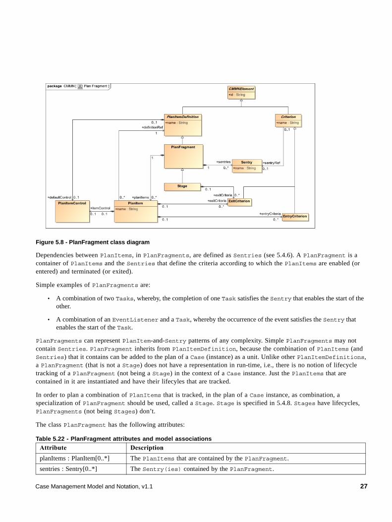
Figure 5.8 - PlanFragment class diagram
Dependencies between PlanItems, in PlanFragments, are defined as Sentries (see 5.4.6). A PlanFragment is a container of PlanItems and the Sentries that define the criteria according to which the PlanItems are enabled (or entered) and terminated (or exited).
Simple examples of PlanFragments are:
• A combination of two Tasks, whereby, the completion of one Task satisfies the Sentry that enables the start of the other.
• A combination of an EventListener and a Task, whereby the occurrence of the event satisfies the Sentry that enables the start of the Task.
PlanFragments can represent PlanItem-and-Sentry patterns of any complexity. Simple PlanFragments may not contain Sentries. PlanFragment inherits from PlanItemDefinition, because the combination of PlanItems (and Sentries) that it contains can be added to the plan of a Case (instance) as a unit. Unlike other PlanItemDefinitions, a PlanFragment (that is not a Stage) does not have a representation in run-time, i.e., there is no notion of lifecycle tracking of a PlanFragment (not being a Stage) in the context of a Case instance. Just the PlanItems that are contained in it are instantiated and have their lifecyles that are tracked.
In order to plan a combination of PlanItems that is tracked, in the plan of a Case instance, as combination, a specialization of PlanFragment should be used, called a Stage. Stage is specified in 5.4.8. Stages have lifecycles, PlanFragments (not being Stages) don’t.
The class PlanFragment has the following attributes:
Table 5.22 - PlanFragment attributes and model associations
Attribute Description
planItems : PlanItem[0..*] The PlanItems that are contained by the PlanFragment.
sentries : Sentry[0..*] The Sentry(ies) contained by the PlanFragment.
Case Management Model and Notation, v1.1 27
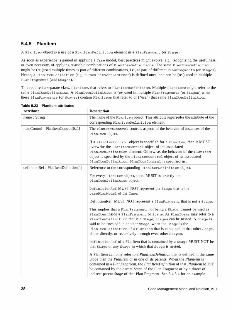
5.4.5 PlanItem
A PlanItem object is a use of a PlanItemDefinition element in a PlanFragment (or Stage).
As soon as experience is gained in applying a Case model, best practices might evolve, e.g., recognizing the usefulness, or even necessity, of applying re-usable combinations of PlanItemDefinitions. The same PlanItemDefinition might be (re-)used multiple times as part of different combinations, i.e., as part of different PlanFragments (or Stages). Hence, a PlanItemDefinition (e.g., a Task or EventListener) is defined once, and can be (re-) used in multiple PlanFragments (and Stages).
This required a separate class, PlanItem, that refers to PlanItemDefinition. Multiple PlanItems might refer to the same PlanItemDefinition. A PlanItemDefinition is (re-)used in multiple PlanFragments (or Stages) when these PlanFragments (or Stages) contain PlanItems that refer to or (“use”) that same PlanItemDefinition.
Table 5.23 - PlanItem attributes
Attribute Description
name : String The name of the PlanItem object. This attribute supersedes the attribute of the corresponding PlanItemDefinition element.
itemControl : PlanItemControl[0..1] The PlanItemControl controls aspects of the behavior of instances of the PlanItem object.
If a PlanItemControl object is specified for a PlanItem, then it MUST overwrite the PlanItemControl object of the associated PlanItemDefinition element. Otherwise, the behavior of the PlanItem object is specified by the PlanItemControl object of its associated PlanItemDefinition. PlanItemControl is specified in .
definitionRef : PlanItemDefinition[1] Reference to the corresponding PlanItemDefinition object.
For every PlanItem object, there MUST be exactly one PlanItemDefinition object.
DefinitionRef MUST NOT represent the Stage that is the casePlanModel of the Case.
DefinitionRef MUST NOT represent a PlanFragment that is not a Stage.
This implies that a PlanFragment, not being a Stage, cannot be used as PlanItem inside a PlanFragment or Stage. As PlanItems may refer to a PlanItemDefinition that is a Stage, Stages can be nested. A Stage is said to be “nested” in another Stage, when the Stage is the PlanItemDefinition of a PlanItem that is contained in that other Stage, either directly, or recursively through even other Stages.
DefinitionRef of a PlanItem that is contained by a Stage MUST NOT be that Stage or any Stage in which that Stage is nested.
A PlanItem can only refer to a PlanItemDefinition that is defined in the same Stage than the PlanItem or in one of its parents. When the PlanItem is contained in a PlanFragment, the PlanItemDefinition of that PlanItem MUST be contained by the parent Stage of the Plan Fragment or by a direct of indirect parent Stage of that Plan Fragment. See 5.4.5.4 for an example.
28 Case Management Model and Notation, v1.1
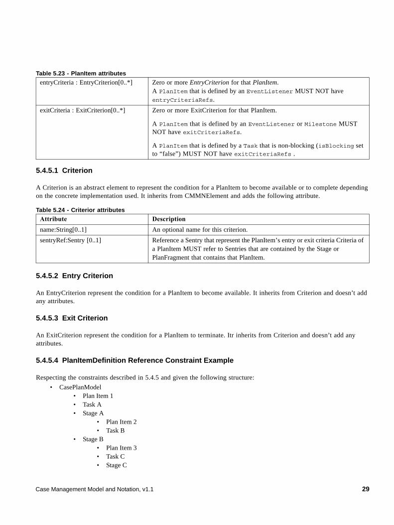
5.4.5.1 Criterion
A Criterion is an abstract element to represent the condition for a PlanItem to become available or to complete depending on the concrete implementation used. It inherits from CMMNElement and adds the following attribute.
5.4.5.2 Entry Criterion
An EntryCriterion represent the condition for a PlanItem to become available. It inherits from Criterion and doesn’t add any attributes.
5.4.5.3 Exit Criterion
An ExitCriterion represent the condition for a PlanItem to terminate. Itr inherits from Criterion and doesn’t add any attributes.
5.4.5.4 PlanItemDefinition Reference Constraint Example
Respecting the constraints described in 5.4.5 and given the following structure:
• CasePlanModel • Plan Item 1 • Task A • Stage A
• Plan Item 2 • Task B
• Stage B • Plan Item 3 • Task C • Stage C
entryCriteria : EntryCriterion[0..*] Zero or more EntryCriterion for that PlanItem.A PlanItem that is defined by an EventListener MUST NOT have entryCriteriaRefs.
exitCriteria : ExitCriterion[0..*] Zero or more ExitCriterion for that PlanItem.
A PlanItem that is defined by an EventListener or Milestone MUST NOT have exitCriteriaRefs.
A PlanItem that is defined by a Task that is non-blocking (isBlocking set to “false”) MUST NOT have exitCriteriaRefs .
Table 5.24 - Criterior attributes
Attribute Description
name:String[0..1] An optional name for this criterion.
sentryRef:Sentry [0..1] Reference a Sentry that represent the PlanItem’s entry or exit criteria Criteria of a PlanItem MUST refer to Sentries that are contained by the Stage or PlanFragment that contains that PlanItem.
Table 5.23 - PlanItem attributes
Case Management Model and Notation, v1.1 29
• Task E • Plan Item 4
• Plan Fragment A • Plan Item 5
Plan Item 1 can refer to Task A, Stage A or Stage B Plan Item 2 can refer to Task A, Stage B or Task B Plan Item 3 can refer to Task A, Stage A, Task C or Stage C Plan Item 4 can refer to Task A, Stage A, Task C or Task E Plan Item 5 can refer to Task A, Stage A or Stage B
5.4.6 Sentry
A Sentry “watches out” for important situations to occur (or “events”), which influence the further proceedings of a Case (and hence their name).
A Sentry is a combination of an “event and/or condition.” When the event is received, a condition might be applied to evaluate whether the event has effect or not. Sentries may take the following form:
1. An event part and a condition part in the form on <event> if <condition> or
2. An event part in the form on <event> or
3. Just a condition part in the form if <condition>
30 Case Management Model and Notation, v1.1
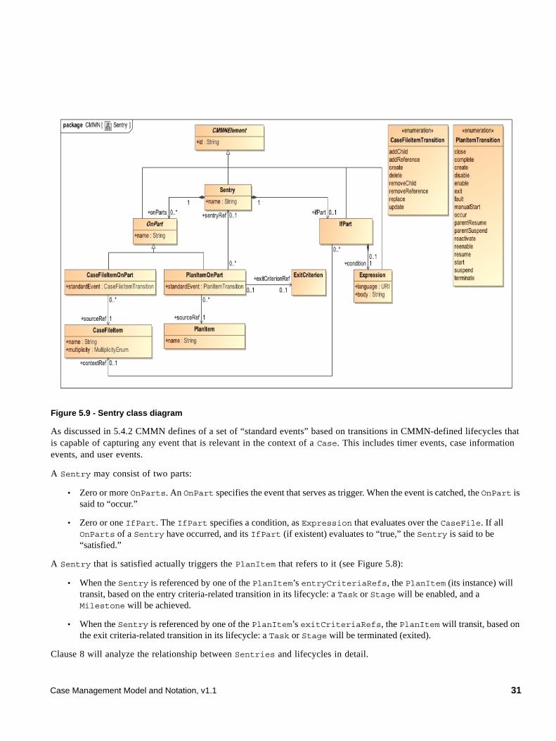
Figure 5.9 - Sentry class diagram
As discussed in 5.4.2 CMMN defines of a set of “standard events” based on transitions in CMMN-defined lifecycles that is capable of capturing any event that is relevant in the context of a Case. This includes timer events, case information events, and user events.
A Sentry may consist of two parts:
• Zero or more OnParts. An OnPart specifies the event that serves as trigger. When the event is catched, the OnPart is said to “occur.”
• Zero or one IfPart. The IfPart specifies a condition, as Expression that evaluates over the CaseFile. If all OnParts of a Sentry have occurred, and its IfPart (if existent) evaluates to “true,” the Sentry is said to be “satisfied.”
A Sentry that is satisfied actually triggers the PlanItem that refers to it (see Figure 5.8):
• When the Sentry is referenced by one of the PlanItem’s entryCriteriaRefs, the PlanItem (its instance) will transit, based on the entry criteria-related transition in its lifecycle: a Task or Stage will be enabled, and a Milestone will be achieved.
• When the Sentry is referenced by one of the PlanItem’s exitCriteriaRefs, the PlanItem will transit, based on the exit criteria-related transition in its lifecycle: a Task or Stage will be terminated (exited).
Clause 8 will analyze the relationship between Sentries and lifecycles in detail.
Case Management Model and Notation, v1.1 31
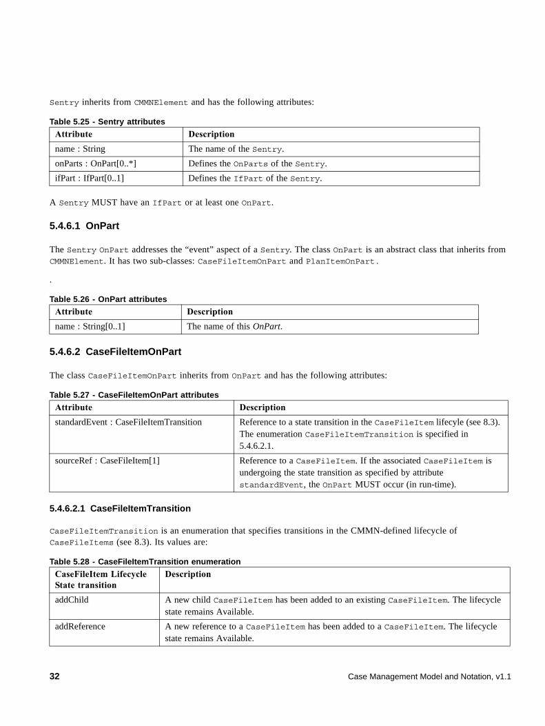
Sentry inherits from CMMNElement and has the following attributes:
A Sentry MUST have an IfPart or at least one OnPart.
5.4.6.1 OnPart
The Sentry OnPart addresses the “event” aspect of a Sentry. The class OnPart is an abstract class that inherits from CMMNElement. It has two sub-classes: CaseFileItemOnPart and PlanItemOnPart.
.
5.4.6.2 CaseFileItemOnPart
The class CaseFileItemOnPart inherits from OnPart and has the following attributes:
5.4.6.2.1 CaseFileItemTransition
CaseFileItemTransition is an enumeration that specifies transitions in the CMMN-defined lifecycle of CaseFileItems (see 8.3). Its values are:
Table 5.25 - Sentry attributes
Attribute Description
name : String The name of the Sentry.
onParts : OnPart[0..*] Defines the OnParts of the Sentry.
ifPart : IfPart[0..1] Defines the IfPart of the Sentry.
Table 5.26 - OnPart attributes
Attribute Description
name : String[0..1] The name of this OnPart.
Table 5.27 - CaseFileItemOnPart attributes
Attribute Description
standardEvent : CaseFileItemTransition Reference to a state transition in the CaseFileItem lifecyle (see 8.3). The enumeration CaseFileItemTransition is specified in 5.4.6.2.1.
sourceRef : CaseFileItem[1] Reference to a CaseFileItem. If the associated CaseFileItem is undergoing the state transition as specified by attribute standardEvent, the OnPart MUST occur (in run-time).
Table 5.28 - CaseFileItemTransition enumeration
CaseFileItem Lifecycle State transition
Description
addChild A new child CaseFileItem has been added to an existing CaseFileItem. The lifecycle state remains Available.
addReference A new reference to a CaseFileItem has been added to a CaseFileItem. The lifecycle state remains Available.
32 Case Management Model and Notation, v1.1
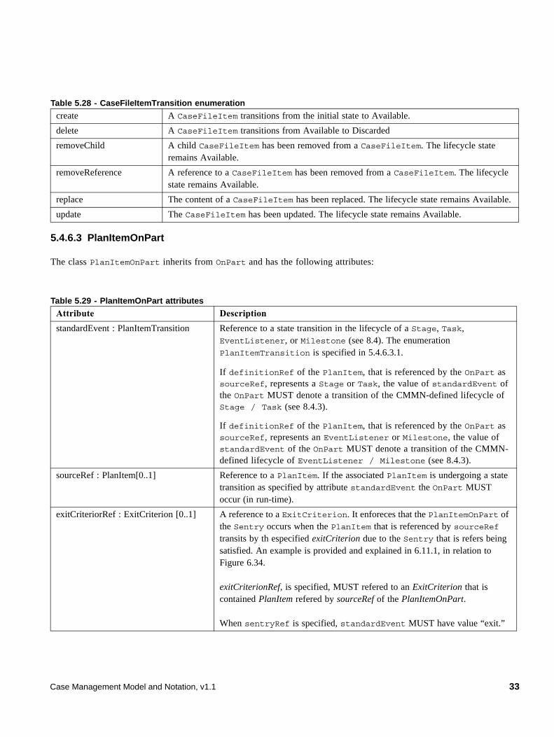
5.4.6.3 PlanItemOnPart
The class PlanItemOnPart inherits from OnPart and has the following attributes:
create A CaseFileItem transitions from the initial state to Available.
delete A CaseFileItem transitions from Available to Discarded
removeChild A child CaseFileItem has been removed from a CaseFileItem. The lifecycle state remains Available.
removeReference A reference to a CaseFileItem has been removed from a CaseFileItem. The lifecycle state remains Available.
replace The content of a CaseFileItem has been replaced. The lifecycle state remains Available.
update The CaseFileItem has been updated. The lifecycle state remains Available.
Table 5.29 - PlanItemOnPart attributes
Attribute Description
standardEvent : PlanItemTransition Reference to a state transition in the lifecycle of a Stage, Task, EventListener, or Milestone (see 8.4). The enumeration PlanItemTransition is specified in 5.4.6.3.1.
If definitionRef of the PlanItem, that is referenced by the OnPart as sourceRef, represents a Stage or Task, the value of standardEvent of the OnPart MUST denote a transition of the CMMN-defined lifecycle of Stage / Task (see 8.4.3).
If definitionRef of the PlanItem, that is referenced by the OnPart as sourceRef, represents an EventListener or Milestone, the value of standardEvent of the OnPart MUST denote a transition of the CMMN-defined lifecycle of EventListener / Milestone (see 8.4.3).
sourceRef : PlanItem[0..1] Reference to a PlanItem. If the associated PlanItem is undergoing a state transition as specified by attribute standardEvent the OnPart MUST occur (in run-time).
exitCriteriorRef : ExitCriterion [0..1] A reference to a ExitCriterion. It enforeces that the PlanItemOnPart of the Sentry occurs when the PlanItem that is referenced by sourceRef transits by th especified exitCriterion due to the Sentry that is refers being satisfied. An example is provided and explained in 6.11.1, in relation to Figure 6.34.
exitCriterionRef, is specified, MUST refered to an ExitCriterion that is contained PlanItem refered by sourceRef of the PlanItemOnPart.
When sentryRef is specified, standardEvent MUST have value “exit.”
Table 5.28 - CaseFileItemTransition enumeration
Case Management Model and Notation, v1.1 33
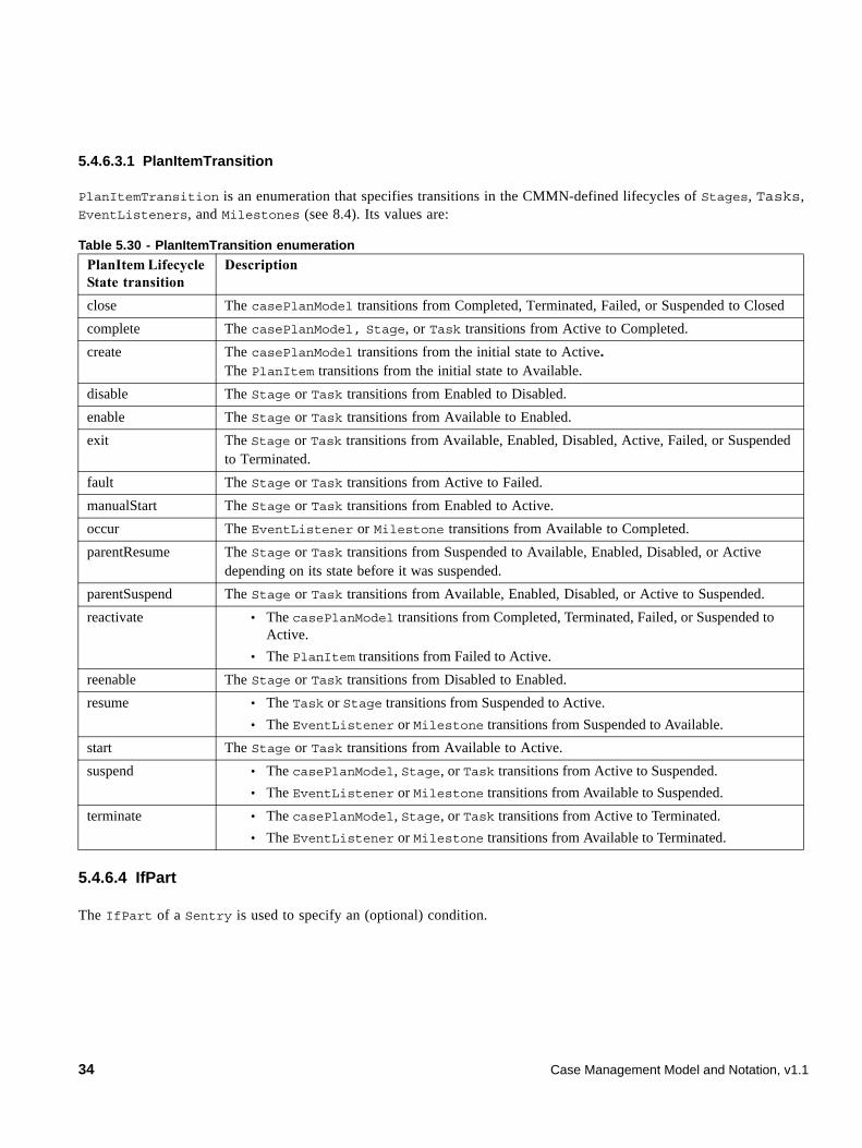
5.4.6.3.1 PlanItemTransition
PlanItemTransition is an enumeration that specifies transitions in the CMMN-defined lifecycles of Stages, Tasks, EventListeners, and Milestones (see 8.4). Its values are:
5.4.6.4 IfPart
The IfPart of a Sentry is used to specify an (optional) condition.
Table 5.30 - PlanItemTransition enumeration
PlanItem Lifecycle State transition
Description
close The casePlanModel transitions from Completed, Terminated, Failed, or Suspended to Closed
complete The casePlanModel, Stage, or Task transitions from Active to Completed.
create The casePlanModel transitions from the initial state to Active.The PlanItem transitions from the initial state to Available.
disable The Stage or Task transitions from Enabled to Disabled.
enable The Stage or Task transitions from Available to Enabled.
exit The Stage or Task transitions from Available, Enabled, Disabled, Active, Failed, or Suspended to Terminated.
fault The Stage or Task transitions from Active to Failed.
manualStart The Stage or Task transitions from Enabled to Active.
occur The EventListener or Milestone transitions from Available to Completed.
parentResume The Stage or Task transitions from Suspended to Available, Enabled, Disabled, or Active depending on its state before it was suspended.
parentSuspend The Stage or Task transitions from Available, Enabled, Disabled, or Active to Suspended.
reactivate • The casePlanModel transitions from Completed, Terminated, Failed, or Suspended to Active.
• The PlanItem transitions from Failed to Active.
reenable The Stage or Task transitions from Disabled to Enabled.
resume • The Task or Stage transitions from Suspended to Active.
• The EventListener or Milestone transitions from Suspended to Available.
start The Stage or Task transitions from Available to Active.
suspend • The casePlanModel, Stage, or Task transitions from Active to Suspended.
• The EventListener or Milestone transitions from Available to Suspended.
terminate • The casePlanModel, Stage, or Task transitions from Active to Terminated.
• The EventListener or Milestone transitions from Available to Terminated.
34 Case Management Model and Notation, v1.1
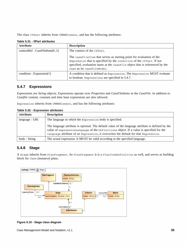
The class IfPart inherits from CMMNElement, and has the following attributes:
5.4.7 Expressions
Expressions are String objects. Expressions operate over Properties and CaseFileItems in the CaseFile. In addition to Casefile content, constant and time base expressions are also allowed.
Expression inherits from CMMNElement, and has the following attributes:
5.4.8 Stage
A Stage inherits from PlanFragment. As PlanFragment it is a PlanItemDefinition as well, and serves as building block for Case (instance) plans.
Figure 5.10 - Stage class diagram
Table 5.31 - IfPart attributes
Attribute Description
contextRef : CaseFileItem[0..1] The context of the IfPart.
The caseFileItem that serves as starting point for evaluation of the Expression that is specified by the condition of the IfPart. If not specified, evaluation starts at the CaseFile object that is referenced by the Case as its caseFileModel.
condition : Expression[1] A condition that is defined as Expression. The Expression MUST evaluate to boolean. Expressions are specified in 5.4.7.
Table 5.32 - Expression attributes
Attribute Description
language : URI The language in which the Expression body is specified.
The language attribute is optional. The default value of the language attribute is defined by the value of expressionLanguage of the Definitions object. If a value is specified for the language attribute of an Expression, it overwrites the default for that Expression.
body : String The actual expression. It MUST be valid according to the specified language.
Case Management Model and Notation, v1.1 35
As a PlanFragment, a Stage can contain PlanItems and Sentries.
Unlike PlanFragments (that are not Stages), Stages do have run-time representations in a Case (instance) plan. Instances of Stages are tracked through the CMMN-defined Stage lifecycle (see 8.4.2). Stages may be considered “episodes” of a Case, though Case models allow for defining Stages that can be planned in parallel also.
The following is supported for a Stage, which is not supported for a PlanFragment (that is not a Stage):
• A Stage can be used as PlanItem inside PlanFragments or other Stages.
• A Stage (instance) can serve as context for planning (i.e., a Stage can have a PlanningTable) to support users in planning additional (“discretionary”) items into instances of the Stage in run-time. PlanningTables and DiscretionaryItems are specified in 5.4.9.
• The Case refers to a Stage as its casePlanModel. This defines the “most outer” Stage of the Case.
• This “most outer” Stage of the Case may also contain Sentries that serve as exit criteria for that Stage, and hence for the Case.
The class Stage has the following attributes:
5.4.9 PlanningTable
Planning is a run-time effort. A PlanningTable defines the scope of planning, in terms of identifying a sub-set of PlanItemDefinitions that can be considered for planning in a certain context. The context for planning might be:
Table 5.33 - Stage attributes
Attribute Description
planItemDefinitions : PlanItemDefinition[0..*] This attribute lists the PlanItemDefinition objects available in the Stage, and its nested Stages.
autoComplete : Boolean = false This attribute controls completion of the Stage. If “false,” a Stage requires a user to manually complete it, which is often appropriate for Stages that contain “discretionary” items (see 5.4.9.2) and/or non-required Tasks or Stages (see 5.4.11.2). Stage completion logic is specified in detail in 8.6.1.
planningTable : PlanningTable[0..1] Defines the (optional) PlanningTable of the Stage. PlanningTable is specified in 5.4.9.
exitCriteria : ExitCriterion[0..*] Define zero or more ExitCriterion (see 5.4.5.2) that serve as the exit criteria for the Stage.
ExitCriterion of a Stage MUST refer to Sentries that are contained by that Stage.
Only the Stage that is referenced by the Case as its casePlanningModel can have exitCriteria. Note that it is only useful for that Stage to directly have exitCriteria, as it cannot be further nested in other Stages (other Stages can contain both PlanItems that represent Stages and the Sentries that impose entry and/or exit criteria on them).
36 Case Management Model and Notation, v1.1
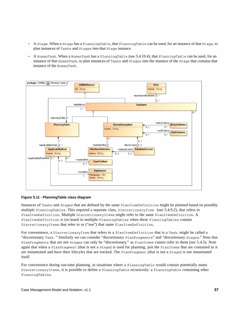
• A Stage. When a Stage has a PlanningTable, that PlanningTable can be used, for an instance of that Stage, to plan instances of Tasks and Stages into that Stage instance.
• A HumanTask. When a HumanTask has a PlanningTable (see 5.4.10.4), that PlanningTable can be used, for an instance of that HumanTask, to plan instances of Tasks and Stages into the instance of the Stage that contains that instance of the HumanTask.
Figure 5.11 - PlanningTable class diagram
Instances of Tasks and Stages that are defined by the same PlanItemDefinition might be planned based on possibly multiple PlanningTables. This required a separate class, DiscretionaryItem (see 5.4.9.2), that refers to PlanItemDefinition. Multiple DiscretionaryItems might refer to the same PlanItemDefinition. A PlanItemDefinition is (re-)used in multiple PlanningTables when these PlanningTables contain DiscretionaryItems that refer to or (“use”) that same PlanItemDefinition.
For convenience, a DiscretionaryItem that refers to a PlanItemDefinition that is a Task, might be called a “discretionary Task.” Similarly we can consider “discretionary PlanFragments” and “discretionary Stages.” Note that PlanFragments that are not Stages can only be “discretionary,” as PlanItems cannot refer to them (see 5.4.5). Note again that when a PlanFragment (that is not a Stage) is used for planning, just the PlanItems that are contained in it are instantiated and have their lifecyles that are tracked. The PlanFragment (that is not a Stage) is not instantiated itself.
For convenience during run-time planning, in situations where a PlanningTable would contain potentially many DiscretionaryItems, it is possible to define a PlanningTable recursively: a PlanningTable containing other PlanningTables.
Case Management Model and Notation, v1.1 37
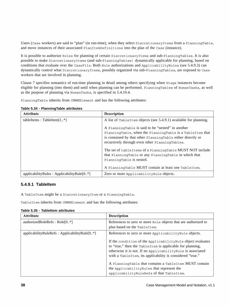
Users (Case workers) are said to “plan” (in run-time), when they select DiscretionaryItems from a PlanningTable, and move instances of their associated PlanItemDefinitions into the plan of the Case (instance).
It is possible to authorize Roles for planning of certain DiscretionaryItems and sub-PlanningTables. It is also possible to make DiscretionaryItems (and sub-PlanningTables) dynamically applicable for planning, based on conditions that evaluate over the CaseFile. Both Role authorizations and ApplicabilityRules (see 5.4.9.3) can dynamically control what DiscretionaryItems, possibly organized via sub-PlanningTables, are exposed to Case workers that are involved in planning.
Clause 7 specifies semantics of run-time planning in detail among others specifying when Stage instances become eligible for planning (into them) and until when planning can be performed. PlanningTables of HumanTasks, as well as the purpose of planning via HumanTasks, is specified in 5.4.10.4.
PlanningTable inherits from CMMNElement and has the following attributes:
5.4.9.1 TableItem
A TableItem might be a DiscretionaryItem or a PlanningTable.
TableItem inherits from CMMNElement and has the following attributes:
Table 5.34 - PlanningTable attributes
Attribute Description
tableItems : TableItem[1..*] A list of TableItem objects (see 5.4.9.1) available for planning.
A PlanningTable is said to be “nested” in another PlanningTable, when the PlanningTable is a TableItem that is contained by that other PlanningTable either directly or recursively through even other PlanningTables.
The set of tableItems of a PlanningTable MUST NOT include that PlanningTable or any PlanningTable in which that PlanningTable is nested.
A PlanningTable MUST contain at least one TableItem.
applicabilityRules : ApplicabilityRule[0..*] Zero or more ApplicabilityRule objects.
Table 5.35 - TableItem attributes
Attribute Description
authorizedRoleRefs : Role[0..*] References to zero or more Role objects that are authorized to plan based on the TableItem.
applicabilityRuleRefs : ApplicabilityRule[0..*] References to zero or more ApplicabilityRule objects.
If the condition of the ApplicabilityRule object evaluates to “true,” then the TableItem is applicable for planning, otherwise it is not. If no ApplicabilityRule is associated with a TableItem, its applicability is considered “true.”
A PlanningTable that contains a TableItem MUST contain the ApplicabilityRules that represent the applicabilityRuleRefs of that TableItem.
38 Case Management Model and Notation, v1.1
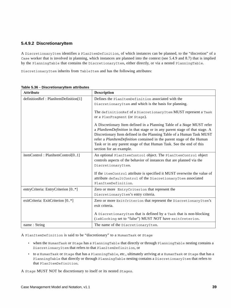
5.4.9.2 DiscretionaryItem
A DiscretionaryItem identifies a PlanItemDefinition, of which instances can be planned, to the “discretion” of a Case worker that is involved in planning, which instances are planned into the context (see 5.4.9 and 8.7) that is implied by the PlanningTable that contains the DiscretionaryItem, either directly, or via a nested PlanningTable.
DiscretionaryItem inherits from TableItem and has the following attributes:
A PlanItemDefinition is said to be “discretionary” to a HumanTask or Stage
• when the HumanTask or Stage has a PlanningTable that directly or through PlanningTable nesting contains a DiscretionaryItem that refers to that PlanItemDefinition, or
• to a HumanTask or Stage that has a PlanningTable, etc., ultimately arriving at a HumanTask or Stage that has a PlanningTable that directly or through PlanningTable nesting contains a DiscretionaryItem that refers to that PlanItemDefinition.
A Stage MUST NOT be discretionary to itself or its nested Stages.
Table 5.36 - DiscretionaryItem attributes
Attribute Description
definitionRef : PlanItemDefinition[1] Defines the PlanItemDefinition associated with the DiscretionaryItem and which is the basis for planning.
The definitionRef of a DiscretionaryItem MUST represent a Task or a PlanFragment (or Stage).
A Discretionary Item defined in a Planning Table of a Stage MUST refer a PlanItemDefinition in that stage or in any parent stage of that stage. A Discretionary Item defined in the Planning Table of a Human Task MUST refer a PlanItemDefinition contained in the parent stage of the Human Task or in any parent stage of that Human Task. See the end of this section for an example.
itemControl : PlanItemControl[0..1] An optional PlanItemControl object. The PlanItemControl object controls aspects of the behavior of instances that are planned via the DiscretionaryItem.
If the itemControl attribute is specified it MUST overwrite the value of attribute defaultControl of the DiscretionaryItem associated PlanItemDefinition.
entryCriteria: EntryCriterion [0..*] Zero or more EntryCriterion that represent the DiscretionaryItem’s entry criteria.
exitCriteria: ExitCriterion [0..*] Zero or more ExitCriterion that represent the DiscretionaryItem’s exit criteria.
A DiscretionaryItem that is defined by a Task that is non-blocking (isBlocking set to “false”) MUST NOT have exitCreterion.
name : String The name of the DiscretionaryItem.
Case Management Model and Notation, v1.1 39
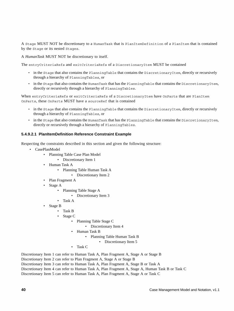
A Stage MUST NOT be discretionary to a HumanTask that is PlanItemDefinition of a PlanItem that is contained by the Stage or its nested Stages.
A HumanTask MUST NOT be discretionary to itself.
The entryCriteriaRefs and exitCriteriaRefs of a DiscretionaryItem MUST be contained
• in the Stage that also contains the PlanningTable that contains the DiscretionaryItem, directly or recursively through a hierarchy of PlanningTables, or
• in the Stage that also contains the HumanTask that has the PlanningTable that contains the DiscretionaryItem, directly or recursively through a hierarchy of PlanningTables.
When entryCriteriaRefs or exitCriteriaRefs of a DiscretionaryItem have OnParts that are PlanItem OnParts, these OnParts MUST have a sourceRef that is contained
• in the Stage that also contains the PlanningTable that contains the DiscretionaryItem, directly or recursively through a hierarchy of PlanningTables, or
• in the Stage that also contains the HumanTask that has the PlanningTable that contains the DiscretionaryItem, directly or recursively through a hierarchy of PlanningTables.
5.4.9.2.1 PlanItemDefinition Reference Constraint Example
Respecting the constraints described in this section and given the following structure:
• CasePlanModel • Planning Table Case Plan Model
• Discretionary Item 1 • Human Task A
• Planning Table Human Task A • Discretionary Item 2
• Plan Fragment A • Stage A
• Planning Table Stage A • Discretionary Item 3
• Task A • Stage B
• Task B • Stage C
• Planning Table Stage C • Discretionary Item 4
• Human Task B • Planning Table Human Task B
• Discretionary Item 5 • Task C
Discretionary Item 1 can refer to Human Task A, Plan Fragment A, Stage A or Stage B Discretionary Item 2 can refer to Plan Fragment A, Stage A or Stage B Discretionary Item 3 can refer to Human Task A, Plan Fragment A, Stage B or Task A Discretionary Item 4 can refer to Human Task A, Plan Fragment A, Stage A, Human Task B or Task C Discretionary Item 5 can refer to Human Task A, Plan Fragment A, Stage A or Task C
40 Case Management Model and Notation, v1.1
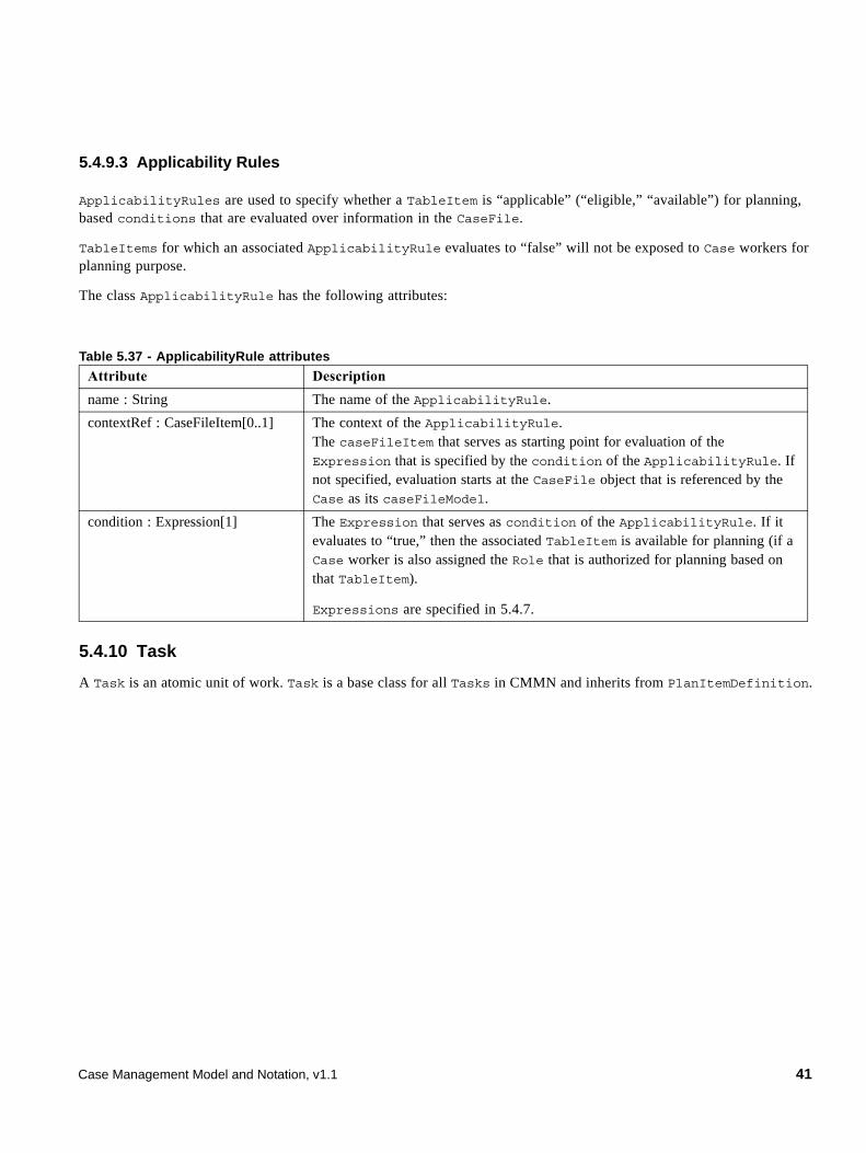
5.4.9.3 Applicability Rules
ApplicabilityRules are used to specify whether a TableItem is “applicable” (“eligible,” “available”) for planning, based conditions that are evaluated over information in the CaseFile.
TableItems for which an associated ApplicabilityRule evaluates to “false” will not be exposed to Case workers for planning purpose.
The class ApplicabilityRule has the following attributes:
5.4.10 Task
A Task is an atomic unit of work. Task is a base class for all Tasks in CMMN and inherits from PlanItemDefinition.
Table 5.37 - ApplicabilityRule attributes
Attribute Description
name : String The name of the ApplicabilityRule.
contextRef : CaseFileItem[0..1] The context of the ApplicabilityRule.The caseFileItem that serves as starting point for evaluation of the Expression that is specified by the condition of the ApplicabilityRule. If not specified, evaluation starts at the CaseFile object that is referenced by the Case as its caseFileModel.
condition : Expression[1] The Expression that serves as condition of the ApplicabilityRule. If it evaluates to “true,” then the associated TableItem is available for planning (if a Case worker is also assigned the Role that is authorized for planning based on that TableItem).
Expressions are specified in 5.4.7.
Case Management Model and Notation, v1.1 41
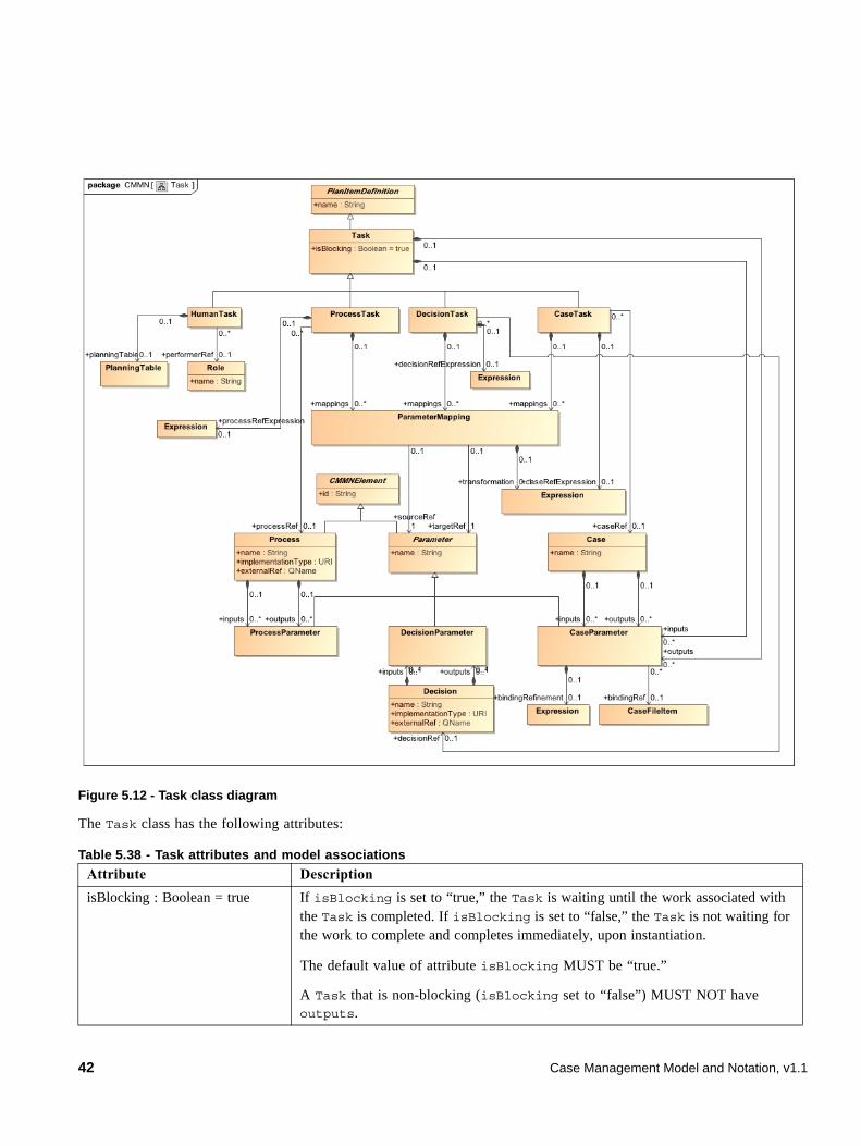
Figure 5.12 - Task class diagram
The Task class has the following attributes:
Table 5.38 - Task attributes and model associations
Attribute Description
isBlocking : Boolean = true If isBlocking is set to “true,” the Task is waiting until the work associated with the Task is completed. If isBlocking is set to “false,” the Task is not waiting for the work to complete and completes immediately, upon instantiation.
The default value of attribute isBlocking MUST be “true.”
A Task that is non-blocking (isBlocking set to “false”) MUST NOT have outputs.
42 Case Management Model and Notation, v1.1
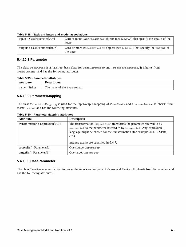
5.4.10.1 Parameter
The class Parameter is an abstract base class for CaseParameter and ProcessParameter. It inherits from CMMNElement, and has the following attributes:
5.4.10.2 ParameterMapping
The class ParameterMapping is used for the input/output mapping of CaseTasks and ProcessTasks. It inherits from CMMNElement and has the following attributes:
5.4.10.3 CaseParameter
The class CaseParameter is used to model the inputs and outputs of Cases and Tasks. It inherits from Parameter and has the following attributes:
inputs : CaseParameter[0..*] Zero or more CaseParameter objects (see 5.4.10.3) that specify the input of the Task.
outputs : CaseParameter[0..*] Zero or more CaseParameter objects (see 5.4.10.3) that specify the output of the Task.
Table 5.39 - Parameter attributes
Attribute Description
name : String The name of the Parameter.
Table 5.40 - ParameterMapping attributes
Attribute Description
transformation : Expression[0..1] The transformation Expression transforms the parameter referred to by sourceRef to the parameter referred to by targetRef. Any expression language might be chosen for the transformation (for example XSLT, XPath, etc.).
Expressions are specified in 5.4.7.
sourceRef : Parameter[1] One source Parameter.
targetRef : Parameter[1] One target Parameter.
Table 5.38 - Task attributes and model associations
Case Management Model and Notation, v1.1 43
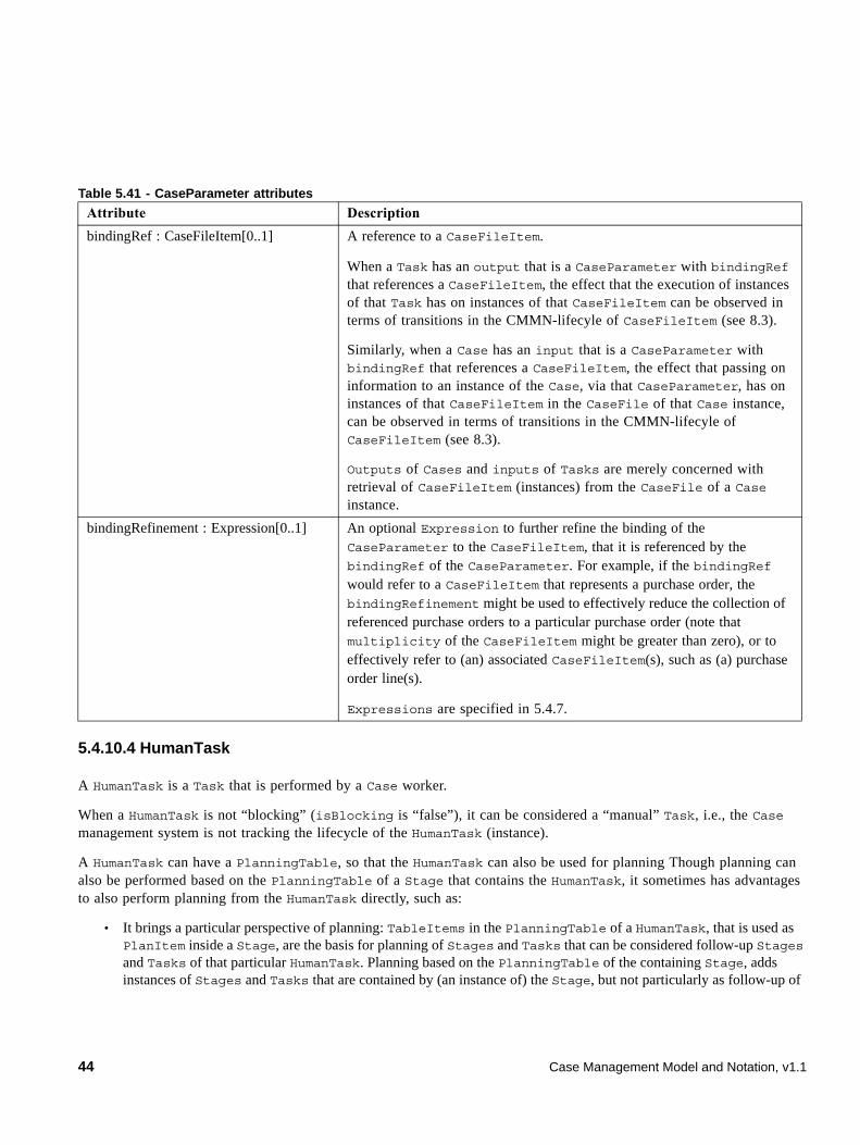
5.4.10.4 HumanTask
A HumanTask is a Task that is performed by a Case worker.
When a HumanTask is not “blocking” (isBlocking is “false”), it can be considered a “manual” Task, i.e., the Case management system is not tracking the lifecycle of the HumanTask (instance).
A HumanTask can have a PlanningTable, so that the HumanTask can also be used for planning Though planning can also be performed based on the PlanningTable of a Stage that contains the HumanTask, it sometimes has advantages to also perform planning from the HumanTask directly, such as:
• It brings a particular perspective of planning: TableItems in the PlanningTable of a HumanTask, that is used as PlanItem inside a Stage, are the basis for planning of Stages and Tasks that can be considered follow-up Stages and Tasks of that particular HumanTask. Planning based on the PlanningTable of the containing Stage, adds instances of Stages and Tasks that are contained by (an instance of) the Stage, but not particularly as follow-up of
Table 5.41 - CaseParameter attributes
Attribute Description
bindingRef : CaseFileItem[0..1] A reference to a CaseFileItem.
When a Task has an output that is a CaseParameter with bindingRef that references a CaseFileItem, the effect that the execution of instances of that Task has on instances of that CaseFileItem can be observed in terms of transitions in the CMMN-lifecyle of CaseFileItem (see 8.3).
Similarly, when a Case has an input that is a CaseParameter with bindingRef that references a CaseFileItem, the effect that passing on information to an instance of the Case, via that CaseParameter, has on instances of that CaseFileItem in the CaseFile of that Case instance, can be observed in terms of transitions in the CMMN-lifecyle of CaseFileItem (see 8.3).
Outputs of Cases and inputs of Tasks are merely concerned with retrieval of CaseFileItem (instances) from the CaseFile of a Case instance.
bindingRefinement : Expression[0..1] An optional Expression to further refine the binding of the CaseParameter to the CaseFileItem, that it is referenced by the bindingRef of the CaseParameter. For example, if the bindingRef would refer to a CaseFileItem that represents a purchase order, the bindingRefinement might be used to effectively reduce the collection of referenced purchase orders to a particular purchase order (note that multiplicity of the CaseFileItem might be greater than zero), or to effectively refer to (an) associated CaseFileItem(s), such as (a) purchase order line(s).
Expressions are specified in 5.4.7.
44 Case Management Model and Notation, v1.1
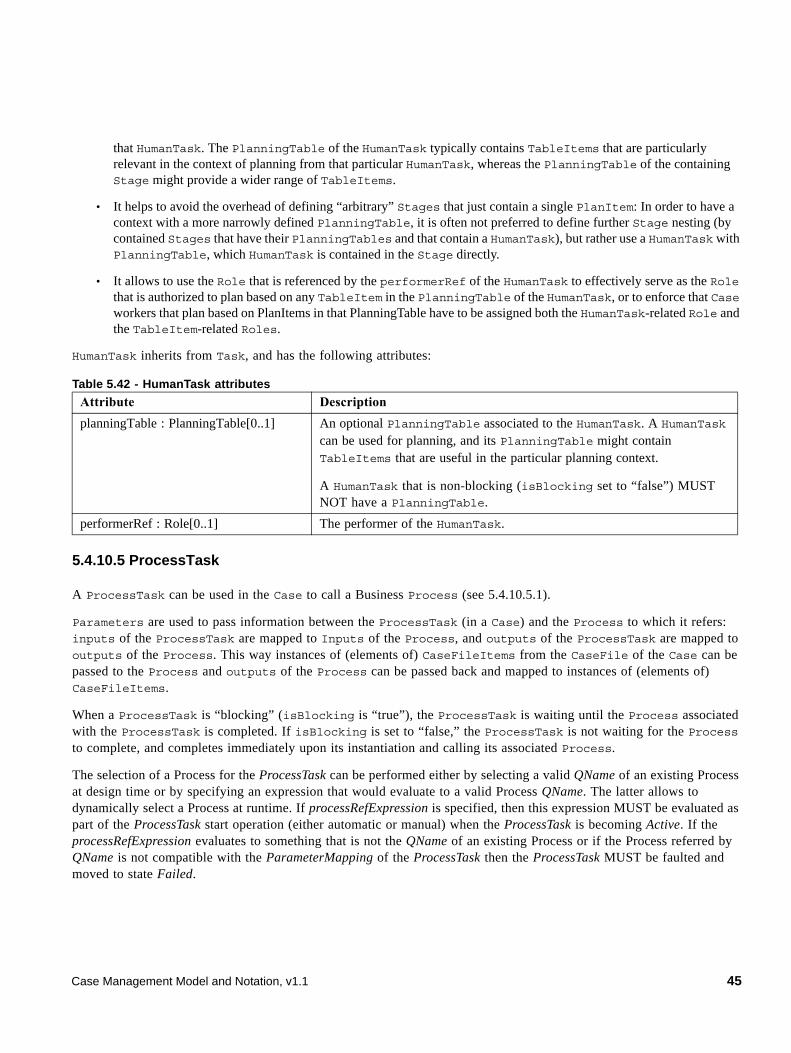
that HumanTask. The PlanningTable of the HumanTask typically contains TableItems that are particularly relevant in the context of planning from that particular HumanTask, whereas the PlanningTable of the containing Stage might provide a wider range of TableItems.
• It helps to avoid the overhead of defining “arbitrary” Stages that just contain a single PlanItem: In order to have a context with a more narrowly defined PlanningTable, it is often not preferred to define further Stage nesting (by contained Stages that have their PlanningTables and that contain a HumanTask), but rather use a HumanTask with PlanningTable, which HumanTask is contained in the Stage directly.
• It allows to use the Role that is referenced by the performerRef of the HumanTask to effectively serve as the Role that is authorized to plan based on any TableItem in the PlanningTable of the HumanTask, or to enforce that Case workers that plan based on PlanItems in that PlanningTable have to be assigned both the HumanTask-related Role and the TableItem-related Roles.
HumanTask inherits from Task, and has the following attributes:
5.4.10.5 ProcessTask
A ProcessTask can be used in the Case to call a Business Process (see 5.4.10.5.1).
Parameters are used to pass information between the ProcessTask (in a Case) and the Process to which it refers: inputs of the ProcessTask are mapped to Inputs of the Process, and outputs of the ProcessTask are mapped to outputs of the Process. This way instances of (elements of) CaseFileItems from the CaseFile of the Case can be passed to the Process and outputs of the Process can be passed back and mapped to instances of (elements of) CaseFileItems.
When a ProcessTask is “blocking” (isBlocking is “true”), the ProcessTask is waiting until the Process associated with the ProcessTask is completed. If isBlocking is set to “false,” the ProcessTask is not waiting for the Process to complete, and completes immediately upon its instantiation and calling its associated Process.
The selection of a Process for the ProcessTask can be performed either by selecting a valid QName of an existing Process at design time or by specifying an expression that would evaluate to a valid Process QName. The latter allows to dynamically select a Process at runtime. If processRefExpression is specified, then this expression MUST be evaluated as part of the ProcessTask start operation (either automatic or manual) when the ProcessTask is becoming Active. If the processRefExpression evaluates to something that is not the QName of an existing Process or if the Process referred by QName is not compatible with the ParameterMapping of the ProcessTask then the ProcessTask MUST be faulted and moved to state Failed.
Table 5.42 - HumanTask attributes
Attribute Description
planningTable : PlanningTable[0..1] An optional PlanningTable associated to the HumanTask. A HumanTask can be used for planning, and its PlanningTable might contain TableItems that are useful in the particular planning context.
A HumanTask that is non-blocking (isBlocking set to “false”) MUST NOT have a PlanningTable.
performerRef : Role[0..1] The performer of the HumanTask.
Case Management Model and Notation, v1.1 45
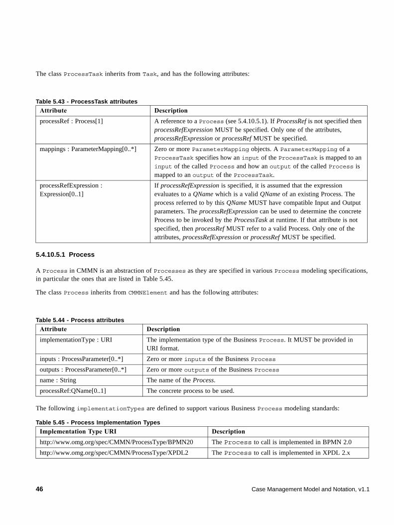
The class ProcessTask inherits from Task, and has the following attributes:
5.4.10.5.1 Process
A Process in CMMN is an abstraction of Processes as they are specified in various Process modeling specifications, in particular the ones that are listed in Table 5.45.
The class Process inherits from CMMNElement and has the following attributes:
The following implementationTypes are defined to support various Business Process modeling standards:
Table 5.43 - ProcessTask attributes
Attribute Description
processRef : Process[1] A reference to a Process (see 5.4.10.5.1). If ProcessRef is not specified then processRefExpression MUST be specified. Only one of the attributes, processRefExpression or processRef MUST be specified.
mappings : ParameterMapping[0..*] Zero or more ParameterMapping objects. A ParameterMapping of a ProcessTask specifies how an input of the ProcessTask is mapped to an input of the called Process and how an output of the called Process is mapped to an output of the ProcessTask.
processRefExpression : Expression[0..1]
If processRefExpression is specified, it is assumed that the expression evaluates to a QName which is a valid QName of an existing Process. The process referred to by this QName MUST have compatible Input and Output parameters. The processRefExpression can be used to determine the concrete Process to be invoked by the ProcessTask at runtime. If that attribute is not specified, then processRef MUST refer to a valid Process. Only one of the attributes, processRefExpression or processRef MUST be specified.
Table 5.44 - Process attributes
Attribute Description
implementationType : URI The implementation type of the Business Process. It MUST be provided in URI format.
inputs : ProcessParameter[0..*] Zero or more inputs of the Business Process
outputs : ProcessParameter[0..*] Zero or more outputs of the Business Process
name : String The name of the Process.
processRef:QName[0..1] The concrete process to be used.
Table 5.45 - Process Implementation Types
Implementation Type URI Description
http://www.omg.org/spec/CMMN/ProcessType/BPMN20 The Process to call is implemented in BPMN 2.0
http://www.omg.org/spec/CMMN/ProcessType/XPDL2 The Process to call is implemented in XPDL 2.x
46 Case Management Model and Notation, v1.1
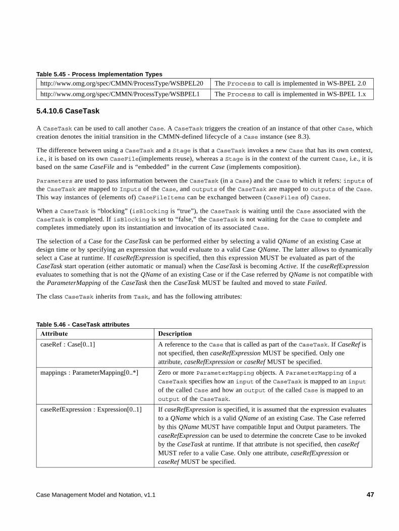
5.4.10.6 CaseTask
A CaseTask can be used to call another Case. A CaseTask triggers the creation of an instance of that other Case, which creation denotes the initial transition in the CMMN-defined lifecycle of a Case instance (see 8.3).
The difference between using a CaseTask and a Stage is that a CaseTask invokes a new Case that has its own context, i.e., it is based on its own CaseFile(implements reuse), whereas a Stage is in the context of the current Case, i.e., it is based on the same CaseFile and is “embedded” in the current Case (implements composition).
Parameters are used to pass information between the CaseTask (in a Case) and the Case to which it refers: inputs of the CaseTask are mapped to Inputs of the Case, and outputs of the CaseTask are mapped to outputs of the Case. This way instances of (elements of) CaseFileItems can be exchanged between (CaseFiles of) Cases.
When a CaseTask is “blocking” (isBlocking is “true”), the CaseTask is waiting until the Case associated with the CaseTask is completed. If isBlocking is set to “false,” the CaseTask is not waiting for the Case to complete and completes immediately upon its instantiation and invocation of its associated Case.
The selection of a Case for the CaseTask can be performed either by selecting a valid QName of an existing Case at design time or by specifying an expression that would evaluate to a valid Case QName. The latter allows to dynamically select a Case at runtime. If caseRefExpression is specified, then this expression MUST be evaluated as part of the CaseTask start operation (either automatic or manual) when the CaseTask is becoming Active. If the caseRefExpression evaluates to something that is not the QName of an existing Case or if the Case referred by QName is not compatible with the ParameterMapping of the CaseTask then the CaseTask MUST be faulted and moved to state Failed.
The class CaseTask inherits from Task, and has the following attributes:
http://www.omg.org/spec/CMMN/ProcessType/WSBPEL20 The Process to call is implemented in WS-BPEL 2.0
http://www.omg.org/spec/CMMN/ProcessType/WSBPEL1 The Process to call is implemented in WS-BPEL 1.x
Table 5.46 - CaseTask attributes
Attribute Description
caseRef : Case[0..1] A reference to the Case that is called as part of the CaseTask. If CaseRef is not specified, then caseRefExpression MUST be specified. Only one attribute, caseRefExpression or caseRef MUST be specified.
mappings : ParameterMapping[0..*] Zero or more ParameterMapping objects. A ParameterMapping of a CaseTask specifies how an input of the CaseTask is mapped to an input of the called Case and how an output of the called Case is mapped to an output of the CaseTask.
caseRefExpression : Expression[0..1] If caseRefExpression is specified, it is assumed that the expression evaluates to a QName which is a valid QName of an existing Case. The Case referred by this QName MUST have compatible Input and Output parameters. The caseRefExpression can be used to determine the concrete Case to be invoked by the CaseTask at runtime. If that attribute is not specified, then caseRef MUST refer to a valie Case. Only one attribute, caseRefExpression or caseRef MUST be specified.
Table 5.45 - Process Implementation Types
Case Management Model and Notation, v1.1 47
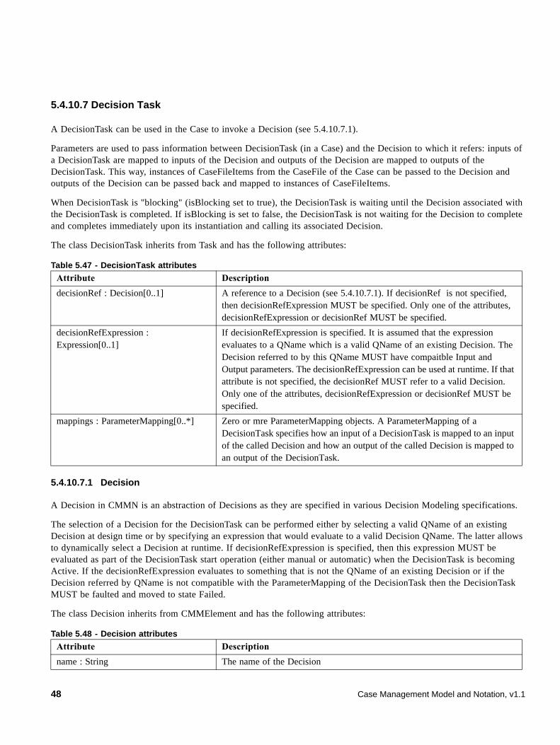
5.4.10.7 Decision Task
A DecisionTask can be used in the Case to invoke a Decision (see 5.4.10.7.1).
Parameters are used to pass information between DecisionTask (in a Case) and the Decision to which it refers: inputs of a DecisionTask are mapped to inputs of the Decision and outputs of the Decision are mapped to outputs of the DecisionTask. This way, instances of CaseFileItems from the CaseFile of the Case can be passed to the Decision and outputs of the Decision can be passed back and mapped to instances of CaseFileItems.
When DecisionTask is "blocking" (isBlocking set to true), the DecisionTask is waiting until the Decision associated with the DecisionTask is completed. If isBlocking is set to false, the DecisionTask is not waiting for the Decision to complete and completes immediately upon its instantiation and calling its associated Decision.
The class DecisionTask inherits from Task and has the following attributes:
5.4.10.7.1 Decision
A Decision in CMMN is an abstraction of Decisions as they are specified in various Decision Modeling specifications.
The selection of a Decision for the DecisionTask can be performed either by selecting a valid QName of an existing Decision at design time or by specifying an expression that would evaluate to a valid Decision QName. The latter allows to dynamically select a Decision at runtime. If decisionRefExpression is specified, then this expression MUST be evaluated as part of the DecisionTask start operation (either manual or automatic) when the DecisionTask is becoming Active. If the decisionRefExpression evaluates to something that is not the QName of an existing Decision or if the Decision referred by QName is not compatible with the ParameterMapping of the DecisionTask then the DecisionTask MUST be faulted and moved to state Failed.
The class Decision inherits from CMMElement and has the following attributes:
Table 5.47 - DecisionTask attributes
Attribute Description
decisionRef : Decision[0..1] A reference to a Decision (see 5.4.10.7.1). If decisionRef is not specified, then decisionRefExpression MUST be specified. Only one of the attributes, decisionRefExpression or decisionRef MUST be specified.
decisionRefExpression : Expression[0..1]
If decisionRefExpression is specified. It is assumed that the expression evaluates to a QName which is a valid QName of an existing Decision. The Decision referred to by this QName MUST have compaitble Input and Output parameters. The decisionRefExpression can be used at runtime. If that attribute is not specified, the decisionRef MUST refer to a valid Decision. Only one of the attributes, decisionRefExpression or decisionRef MUST be specified.
mappings : ParameterMapping[0..*] Zero or mre ParameterMapping objects. A ParameterMapping of a DecisionTask specifies how an input of a DecisionTask is mapped to an input of the called Decision and how an output of the called Decision is mapped to an output of the DecisionTask.
Table 5.48 - Decision attributes
Attribute Description
name : String The name of the Decision
48 Case Management Model and Notation, v1.1
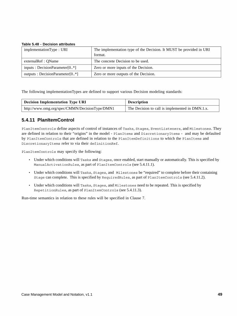
The following implementationTypes are defined to support various Decision modeling standards:
5.4.11 PlanItemControl
PlanItemControls define aspects of control of instances of Tasks, Stages, EventListeners, and Milestones. They are defined in relation to their “origins” in the model - PlanItems and DiscretionaryItems - and may be defaulted by PlanItemControls that are defined in relation to the PlanItemDefinitions to which the PlanItems and DiscretionaryItems refer to via their definitionRef.
PlanItemControls may specify the following:
• Under which conditions will Tasks and Stages, once enabled, start manually or automatically. This is specified by ManualActivationRules, as part of PlanItemControls (see 5.4.11.1).
• Under which conditions will Tasks, Stages, and Milestones be “required” to complete before their containing Stage can complete. This is specified by RequiredRules, as part of PlanItemControls (see 5.4.11.2).
• Under which conditions will Tasks, Stages, and Milestones need to be repeated. This is specified by RepetitionRules, as part of PlanItemControls (see 5.4.11.3).
Run-time semantics in relation to these rules will be specified in Clause 7.
implementationType : URI The implementation type of the Decision. It MUST be provided in URI format.
externalRef : QName The concrete Decision to be used.
inputs : DecisionParameter[0..*] Zero or more inputs of the Decision.
outputs : DecisionParameter[0..*] Zero or more outputs of the Decision.
Decision Implementation Type URI Description
http://www.omg.org/spec/CMMN/DecisionType/DMN1 The Decision to call is implemented in DMN.1.x.
Table 5.48 - Decision attributes
Case Management Model and Notation, v1.1 49
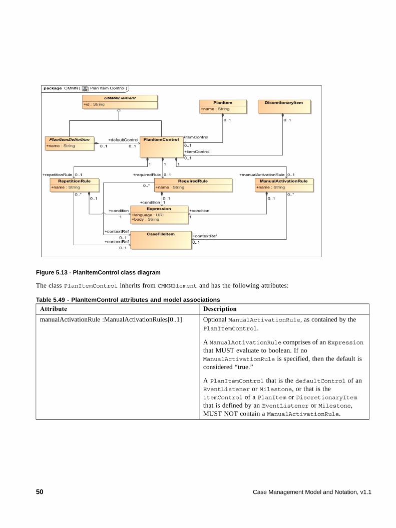
Figure 5.13 - PlanItemControl class diagram
The class PlanItemControl inherits from CMMNElement and has the following attributes:
Table 5.49 - PlanItemControl attributes and model associations
Attribute Description
manualActivationRule :ManualActivationRules[0..1] Optional ManualActivationRule, as contained by the PlanItemControl.
A ManualActivationRule comprises of an Expression that MUST evaluate to boolean. If no ManualActivationRule is specified, then the default is considered “true.”
A PlanItemControl that is the defaultControl of an EventListener or Milestone, or that is the itemControl of a PlanItem or DiscretionaryItem that is defined by an EventListener or Milestone, MUST NOT contain a ManualActivationRule.
50 Case Management Model and Notation, v1.1
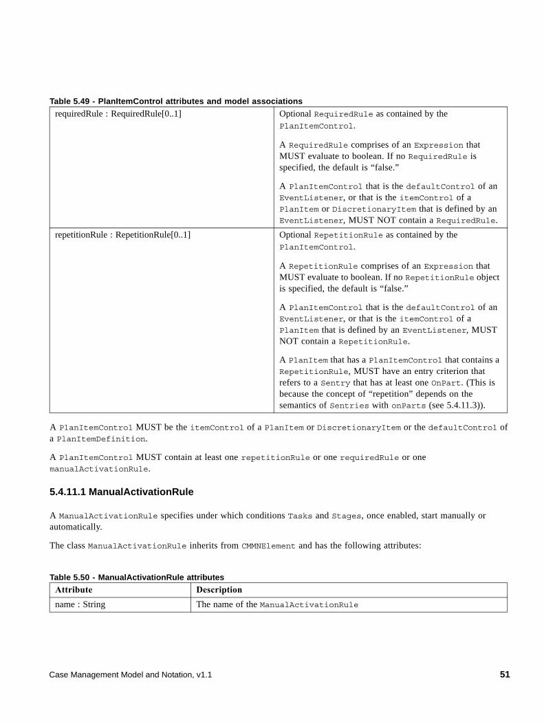
A PlanItemControl MUST be the itemControl of a PlanItem or DiscretionaryItem or the defaultControl of a PlanItemDefinition.
A PlanItemControl MUST contain at least one repetitionRule or one requiredRule or one manualActivationRule.
5.4.11.1 ManualActivationRule
A ManualActivationRule specifies under which conditions Tasks and Stages, once enabled, start manually or automatically.
The class ManualActivationRule inherits from CMMNElement and has the following attributes:
requiredRule : RequiredRule[0..1] Optional RequiredRule as contained by the PlanItemControl.
A RequiredRule comprises of an Expression that MUST evaluate to boolean. If no RequiredRule is specified, the default is “false.”
A PlanItemControl that is the defaultControl of an EventListener, or that is the itemControl of a PlanItem or DiscretionaryItem that is defined by an EventListener, MUST NOT contain a RequiredRule.
repetitionRule : RepetitionRule[0..1] Optional RepetitionRule as contained by the PlanItemControl.
A RepetitionRule comprises of an Expression that MUST evaluate to boolean. If no RepetitionRule object is specified, the default is “false.”
A PlanItemControl that is the defaultControl of an EventListener, or that is the itemControl of a PlanItem that is defined by an EventListener, MUST NOT contain a RepetitionRule.
A PlanItem that has a PlanItemControl that contains a RepetitionRule, MUST have an entry criterion that refers to a Sentry that has at least one OnPart. (This is because the concept of “repetition” depends on the semantics of Sentries with onParts (see 5.4.11.3)).
Table 5.50 - ManualActivationRule attributes
Attribute Description
name : String The name of the ManualActivationRule
Table 5.49 - PlanItemControl attributes and model associations
Case Management Model and Notation, v1.1 51
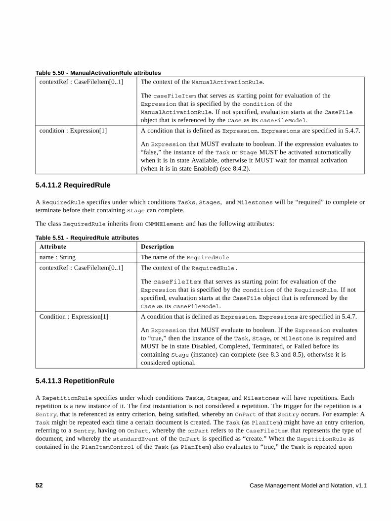
5.4.11.2 RequiredRule
A RequiredRule specifies under which conditions Tasks, Stages, and Milestones will be “required” to complete or terminate before their containing Stage can complete.
The class RequiredRule inherits from CMMNElement and has the following attributes:
5.4.11.3 RepetitionRule
A RepetitionRule specifies under which conditions Tasks, Stages, and Milestones will have repetitions. Each repetition is a new instance of it. The first instantiation is not considered a repetition. The trigger for the repetition is a Sentry, that is referenced as entry criterion, being satisfied, whereby an OnPart of that Sentry occurs. For example: A Task might be repeated each time a certain document is created. The Task (as PlanItem) might have an entry criterion, referring to a Sentry, having on OnPart, whereby the onPart refers to the CaseFileItem that represents the type of document, and whereby the standardEvent of the OnPart is specified as “create.” When the RepetitionRule as contained in the PlanItemControl of the Task (as PlanItem) also evaluates to “true,” the Task is repeated upon
contextRef : CaseFileItem[0..1] The context of the ManualActivationRule.
The caseFileItem that serves as starting point for evaluation of the Expression that is specified by the condition of the ManualActivationRule. If not specified, evaluation starts at the CaseFile object that is referenced by the Case as its caseFileModel.
condition : Expression[1] A condition that is defined as Expression. Expressions are specified in 5.4.7.
An Expression that MUST evaluate to boolean. If the expression evaluates to “false,” the instance of the Task or Stage MUST be activated automatically when it is in state Available, otherwise it MUST wait for manual activation (when it is in state Enabled) (see 8.4.2).
Table 5.51 - RequiredRule attributes
Attribute Description
name : String The name of the RequiredRule
contextRef : CaseFileItem[0..1] The context of the RequiredRule.
The caseFileItem that serves as starting point for evaluation of the Expression that is specified by the condition of the RequiredRule. If not specified, evaluation starts at the CaseFile object that is referenced by the Case as its caseFileModel.
Condition : Expression[1] A condition that is defined as Expression. Expressions are specified in 5.4.7.
An Expression that MUST evaluate to boolean. If the Expression evaluates to “true,” then the instance of the Task, Stage, or Milestone is required and MUST be in state Disabled, Completed, Terminated, or Failed before its containing Stage (instance) can complete (see 8.3 and 8.5), otherwise it is considered optional.
Table 5.50 - ManualActivationRule attributes
52 Case Management Model and Notation, v1.1
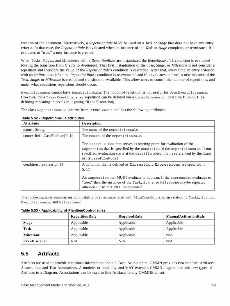
creation of the document. Alternatively, a RepetitionRule MAY be used on a Task or Stage that does not have any entry criteria. In that case, the RepetitionRule is evaluated when an instance of the Task or Stage completes or terminates. If it evaluates to “true,” a new instance is created.
When Tasks, Stages, and Milestones with a RepetitionRole are instantiated the RepetitionRule’s condition is evaluated (during the transition from Create to Available). That first instantiation of the Task, Stage, or Milestone is not consider a repetition and therefore the value of the RepetitionRule’s condition is discarded. After that, every time an entry criterion with an OnPart is satisfied the RepetitionRule’s condition is re-evaluated and if it evaluates to “true” a new instance of the Task, Stage, or Milestone is created and transition to Available. This allow users to control the number of repetitions, and under what conditions repetitions should occur.
EventListeners cannot have RepetitionRule. The notion of repetition is not useful for UserEventListeners. However, for a TimerEventListener repetition can be defined via a timerExpression based on ISO-8601, by defining repeating intervals in it (using “R<n>/” notation).
The class RepetitionRule inherits from CMMNElement and has the following attributes:
The following table summarizes applicability of rules associated with PlanItemControl, in relation to Tasks, Stages, EventListeners, and Milestones:
5.5 Artifacts
Artifacts are used to provide additional information about a Case. At this point, CMMN provides two standard Artifacts: Associations and Text Annotations. A modeler or modeling tool MAY extend a CMMN diagram and add new types of Artifacts to a Diagram. Associations can be used to link Artifacts to any CMMNElement.
Table 5.52 - RepetitionRule attributes
Attribute Description
name : String The name of the RepetitionRule
contextRef : CaseFileItem[0..1] The context of the RepetitionRule.
The caseFileItem that serves as starting point for evaluation of the Expression that is specified by the condition of the RepetitionRule. If not specified, evaluation starts at the CaseFile object that is referenced by the Case as its caseFileModel.
condition : Expression[1] A condition that is defined as Expression. Expressions are specified in 5.4.7.
An Expression that MUST evaluate to boolean. If the Expression evaluates to “true,” then the instance of the Task, Stage, or Milestone maybe repeated, otherwise it MUST NOT be repeated.
Table 5.53 - Applicability of PlanItemControl rules
RepetitionRule RequiredRule ManualActivationRule
Stage Applicable Applicable Applicable
Task Applicable Applicable Applicable
Milestone Applicable Applicable N/A
EventListener N/A N/A N/A
Case Management Model and Notation, v1.1 53
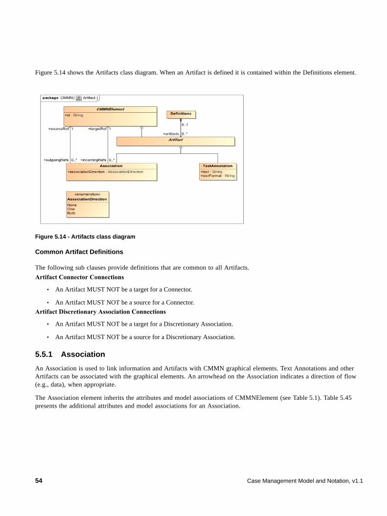
Figure 5.14 shows the Artifacts class diagram. When an Artifact is defined it is contained within the Definitions element.
Figure 5.14 - Artifacts class diagram
Common Artifact Definitions
The following sub clauses provide definitions that are common to all Artifacts.
Artifact Connector Connections
• An Artifact MUST NOT be a target for a Connector.
• An Artifact MUST NOT be a source for a Connector.
Artifact Discretionary Association Connections
• An Artifact MUST NOT be a target for a Discretionary Association.
• An Artifact MUST NOT be a source for a Discretionary Association.
5.5.1 Association
An Association is used to link information and Artifacts with CMMN graphical elements. Text Annotations and other Artifacts can be associated with the graphical elements. An arrowhead on the Association indicates a direction of flow (e.g., data), when appropriate.
The Association element inherits the attributes and model associations of CMMNElement (see Table 5.1). Table 5.45 presents the additional attributes and model associations for an Association.
54 Case Management Model and Notation, v1.1
5.5.2 Text Annotation
Text Annotations are a mechanism for a modeler to provide additional text information for the reader of a CMMN Diagram
The Text Annotation element inherits the attributes and model associations of CMMNElement (see Table 5.46). Table 5.46 presents the additional attributes for a Text Annotation.
Table 5.54 - Association attributes and model associations
Attribute Description
associationDirection : AssociationDirection = None [None | One | Both]
associationDirection is an attributte that defines whether or not the Association shows any directionality with an arrowhead. The default is None (no arrowhead). A value of One means that the arrowhead SHALL be at the Target Object. A value of Both means that there SHALL be an arrowhead at both ends of the Association line.
sourceRef : CMMNElement The CMMNElement that the Association is connecting from.
targetRef : CMMNElement The CMMNElement that the Association is connecting to.
Table 5.55 - Text Annotation attributes
Attribute Description
text : string Text is an attribute that is text that the modeler wishes to communicate to the reader of the Diagram.
textFormat : string This attribute identifies the format of the text. It MUST follow the mime-type format. The default is “text/plain.”
Case Management Model and Notation, v1.1 55

56 Case Management Model and Notation, v1.1
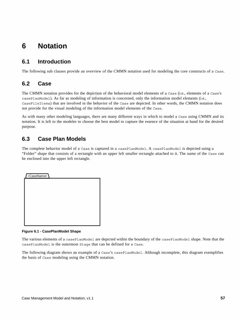
6 Notation
6.1 Introduction
The following sub clauses provide an overview of the CMMN notation used for modeling the core constructs of a Case.
6.2 Case
The CMMN notation provides for the depiction of the behavioral model elements of a Case (i.e., elements of a Case's casePlanModel). As far as modeling of information is concerned, only the information model elements (i.e., CaseFileItems) that are involved in the behavior of the Case are depicted. In other words, the CMMN notation does not provide for the visual modeling of the information model elements of the Case.
As with many other modeling languages, there are many different ways in which to model a Case using CMMN and its notation. It is left to the modeler to choose the best model to capture the essence of the situation at hand for the desired purpose.
6.3 Case Plan Models
The complete behavior model of a Case is captured in a casePlanModel. A casePlanModel is depicted using a “Folder” shape that consists of a rectangle with an upper left smaller rectangle attached to it. The name of the Case can be enclosed into the upper left rectangle.
Figure 6.1 - CasePlanModel Shape
The various elements of a casePlanModel are depicted within the boundary of the casePlanModel shape. Note that the casePlanModel is the outermost Stage that can be defined for a Case.
The following diagram shows an example of a Case’s casePlanModel. Although incomplete, this diagram exemplifies the basis of Case modeling using the CMMN notation.
<CaseName>
Case Management Model and Notation, v1.1 57
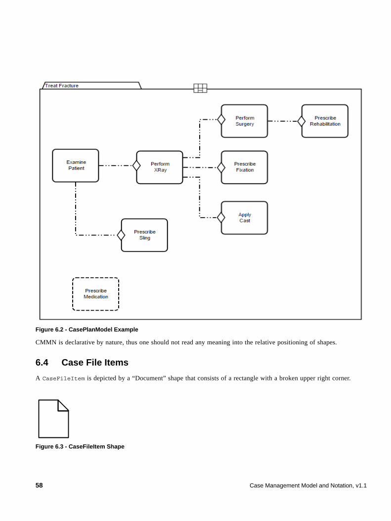
Figure 6.2 - CasePlanModel Example
CMMN is declarative by nature, thus one should not read any meaning into the relative positioning of shapes.
6.4 Case File Items
A CaseFileItem is depicted by a “Document” shape that consists of a rectangle with a broken upper right corner.
Figure 6.3 - CaseFileItem Shape
58 Case Management Model and Notation, v1.1
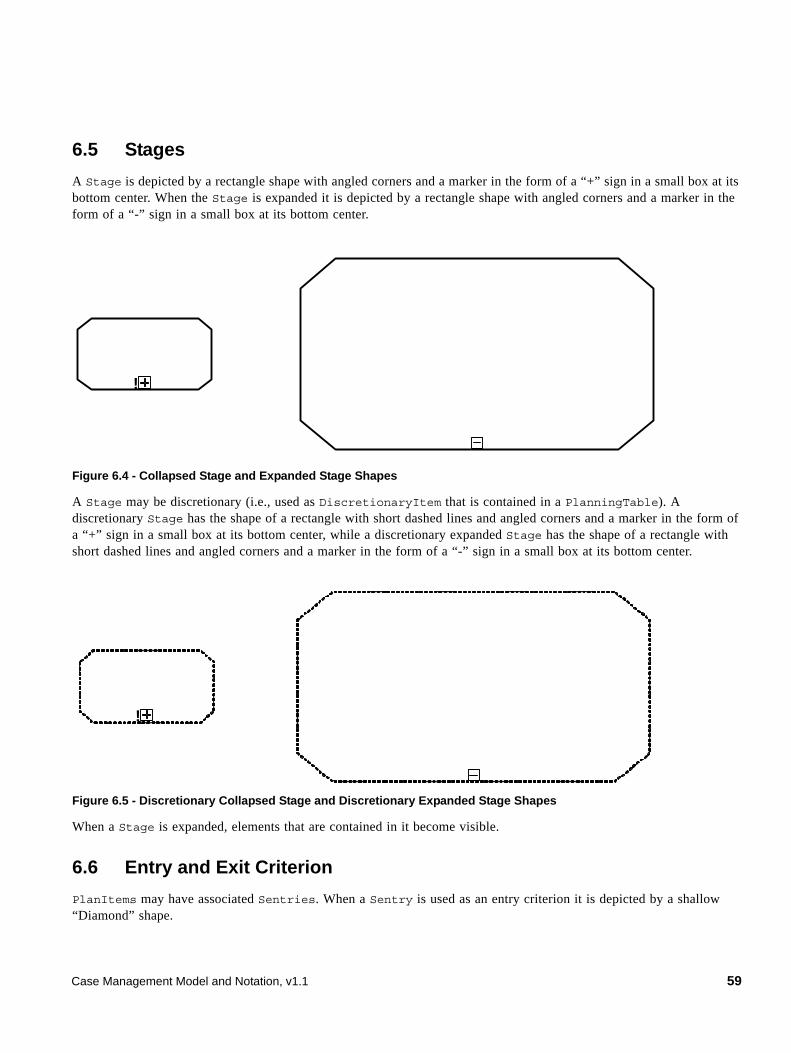
6.5 Stages
A Stage is depicted by a rectangle shape with angled corners and a marker in the form of a “+” sign in a small box at its bottom center. When the Stage is expanded it is depicted by a rectangle shape with angled corners and a marker in the form of a “-” sign in a small box at its bottom center.
Figure 6.4 - Collapsed Stage and Expanded Stage Shapes
A Stage may be discretionary (i.e., used as DiscretionaryItem that is contained in a PlanningTable). A discretionary Stage has the shape of a rectangle with short dashed lines and angled corners and a marker in the form of a “+” sign in a small box at its bottom center, while a discretionary expanded Stage has the shape of a rectangle with short dashed lines and angled corners and a marker in the form of a “-” sign in a small box at its bottom center.
Figure 6.5 - Discretionary Collapsed Stage and Discretionary Expanded Stage Shapes
When a Stage is expanded, elements that are contained in it become visible.
6.6 Entry and Exit Criterion
PlanItems may have associated Sentries. When a Sentry is used as an entry criterion it is depicted by a shallow “Diamond” shape.
!
!
Case Management Model and Notation, v1.1 59
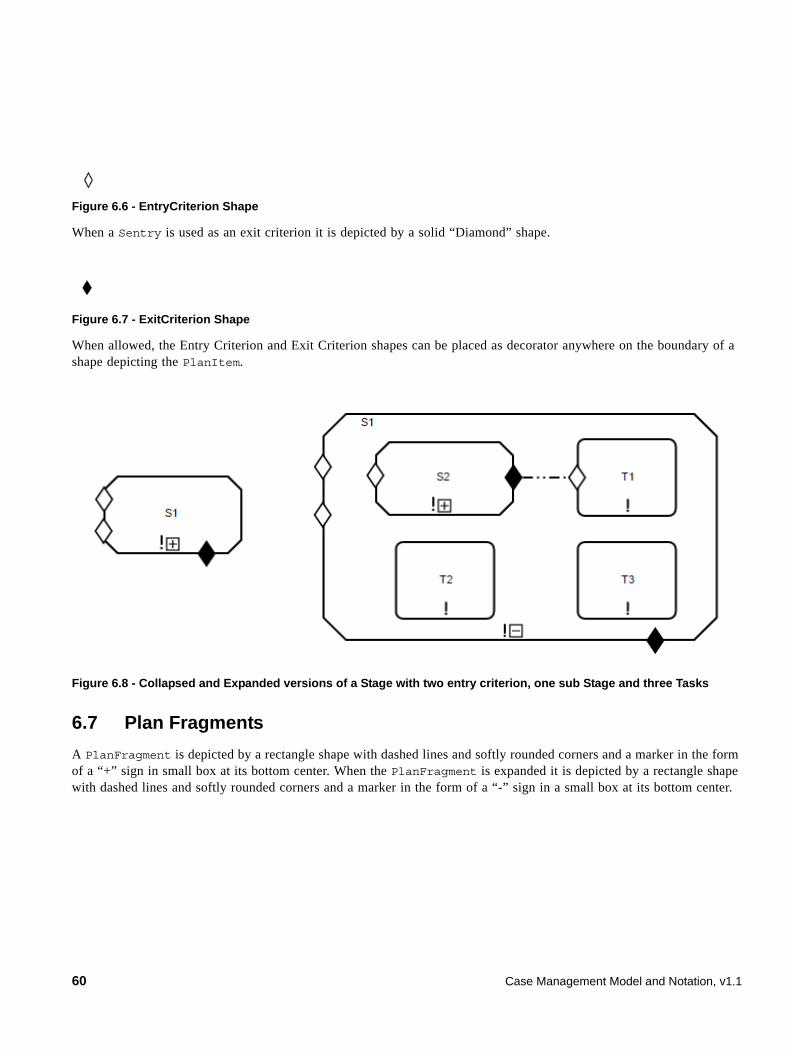
Figure 6.6 - EntryCriterion Shape
When a Sentry is used as an exit criterion it is depicted by a solid “Diamond” shape.
Figure 6.7 - ExitCriterion Shape
When allowed, the Entry Criterion and Exit Criterion shapes can be placed as decorator anywhere on the boundary of a shape depicting the PlanItem.
Figure 6.8 - Collapsed and Expanded versions of a Stage with two entry criterion, one sub Stage and three Tasks
6.7 Plan Fragments
A PlanFragment is depicted by a rectangle shape with dashed lines and softly rounded corners and a marker in the form of a “+” sign in small box at its bottom center. When the PlanFragment is expanded it is depicted by a rectangle shape with dashed lines and softly rounded corners and a marker in the form of a “-” sign in a small box at its bottom center.
60 Case Management Model and Notation, v1.1
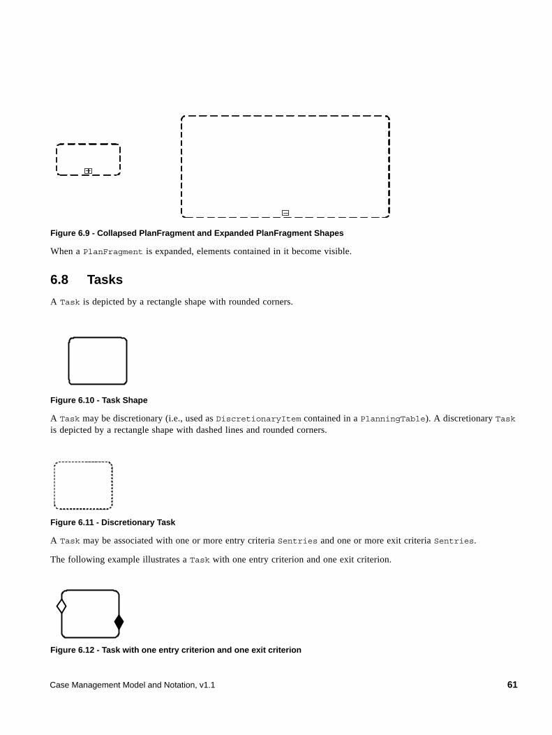
Figure 6.9 - Collapsed PlanFragment and Expanded PlanFragment Shapes
When a PlanFragment is expanded, elements contained in it become visible.
6.8 Tasks
A Task is depicted by a rectangle shape with rounded corners.
Figure 6.10 - Task Shape
A Task may be discretionary (i.e., used as DiscretionaryItem contained in a PlanningTable). A discretionary Task is depicted by a rectangle shape with dashed lines and rounded corners.
Figure 6.11 - Discretionary Task
A Task may be associated with one or more entry criteria Sentries and one or more exit criteria Sentries.
The following example illustrates a Task with one entry criterion and one exit criterion.
Figure 6.12 - Task with one entry criterion and one exit criterion
Case Management Model and Notation, v1.1 61
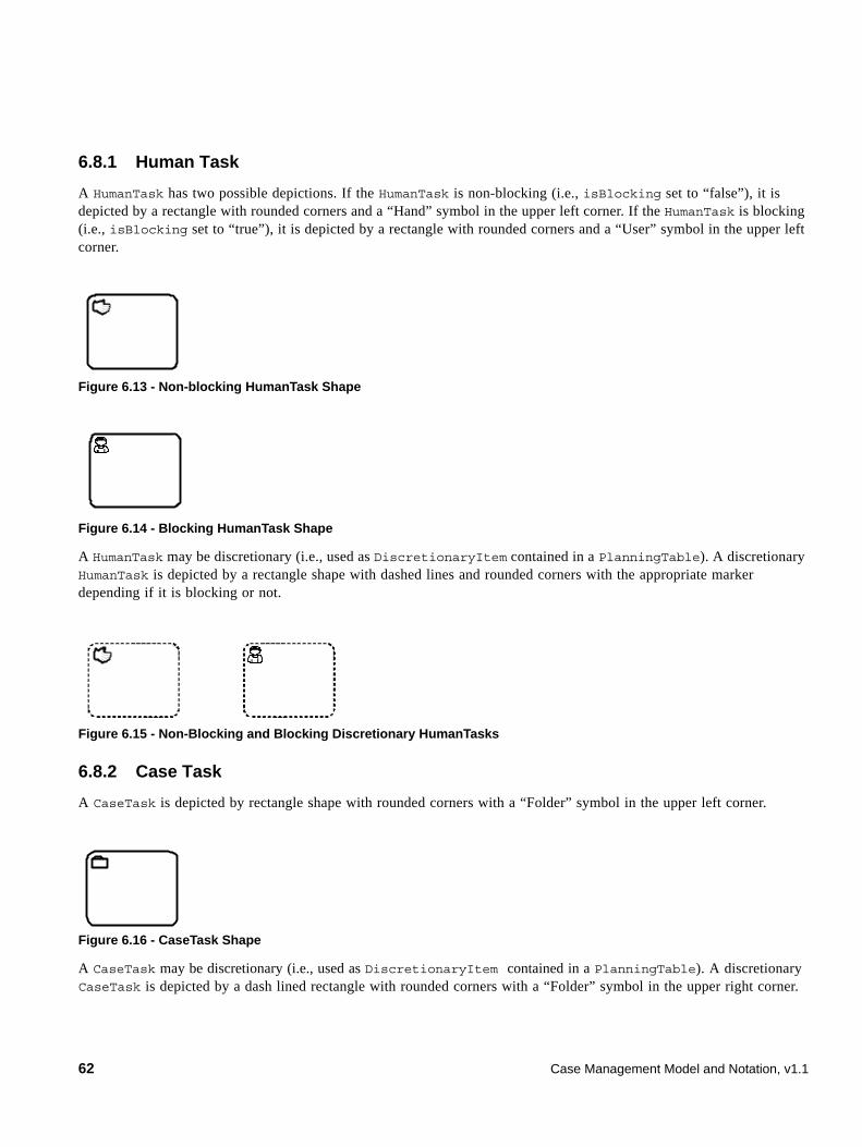
6.8.1 Human Task
A HumanTask has two possible depictions. If the HumanTask is non-blocking (i.e., isBlocking set to “false”), it is depicted by a rectangle with rounded corners and a “Hand” symbol in the upper left corner. If the HumanTask is blocking (i.e., isBlocking set to “true”), it is depicted by a rectangle with rounded corners and a “User” symbol in the upper left corner.
Figure 6.13 - Non-blocking HumanTask Shape
Figure 6.14 - Blocking HumanTask Shape
A HumanTask may be discretionary (i.e., used as DiscretionaryItem contained in a PlanningTable). A discretionary HumanTask is depicted by a rectangle shape with dashed lines and rounded corners with the appropriate marker depending if it is blocking or not.
Figure 6.15 - Non-Blocking and Blocking Discretionary HumanTasks
6.8.2 Case Task
A CaseTask is depicted by rectangle shape with rounded corners with a “Folder” symbol in the upper left corner.
Figure 6.16 - CaseTask Shape
A CaseTask may be discretionary (i.e., used as DiscretionaryItem contained in a PlanningTable). A discretionary CaseTask is depicted by a dash lined rectangle with rounded corners with a “Folder” symbol in the upper right corner.
62 Case Management Model and Notation, v1.1
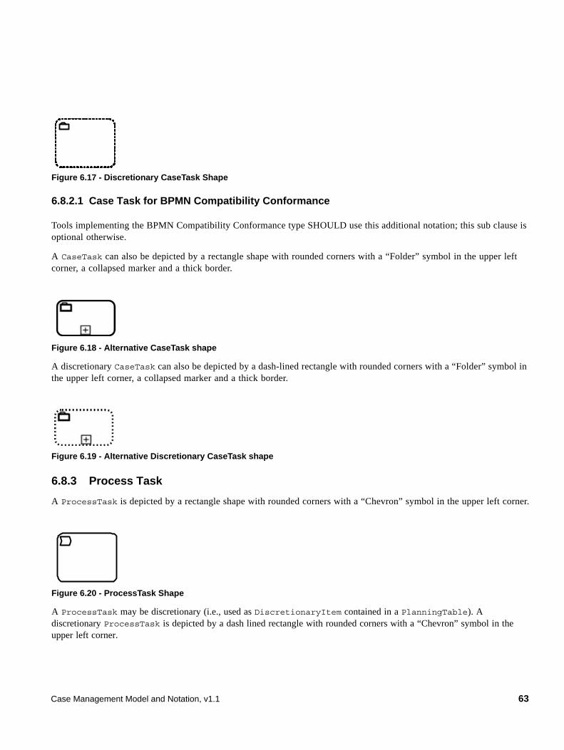
Figure 6.17 - Discretionary CaseTask Shape
6.8.2.1 Case Task for BPMN Compatibility Conformance
Tools implementing the BPMN Compatibility Conformance type SHOULD use this additional notation; this sub clause is optional otherwise.
A CaseTask can also be depicted by a rectangle shape with rounded corners with a “Folder” symbol in the upper left corner, a collapsed marker and a thick border.
Figure 6.18 - Alternative CaseTask shape
A discretionary CaseTask can also be depicted by a dash-lined rectangle with rounded corners with a “Folder” symbol in the upper left corner, a collapsed marker and a thick border.
Figure 6.19 - Alternative Discretionary CaseTask shape
6.8.3 Process Task
A ProcessTask is depicted by a rectangle shape with rounded corners with a “Chevron” symbol in the upper left corner.
Figure 6.20 - ProcessTask Shape
A ProcessTask may be discretionary (i.e., used as DiscretionaryItem contained in a PlanningTable). A discretionary ProcessTask is depicted by a dash lined rectangle with rounded corners with a “Chevron” symbol in the upper left corner.
Case Management Model and Notation, v1.1 63
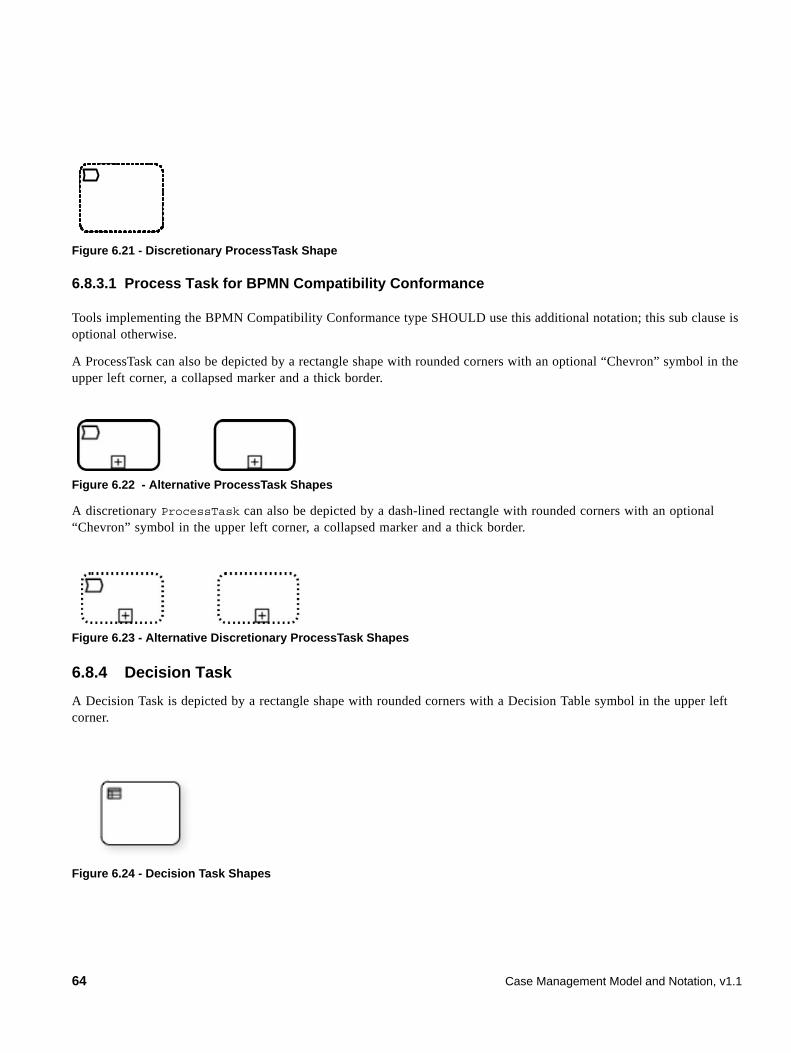
Figure 6.21 - Discretionary ProcessTask Shape
6.8.3.1 Process Task for BPMN Compatibility Conformance
Tools implementing the BPMN Compatibility Conformance type SHOULD use this additional notation; this sub clause is optional otherwise.
A ProcessTask can also be depicted by a rectangle shape with rounded corners with an optional “Chevron” symbol in the upper left corner, a collapsed marker and a thick border.
Figure 6.22 - Alternative ProcessTask Shapes
A discretionary ProcessTask can also be depicted by a dash-lined rectangle with rounded corners with an optional “Chevron” symbol in the upper left corner, a collapsed marker and a thick border.
Figure 6.23 - Alternative Discretionary ProcessTask Shapes
6.8.4 Decision Task
A Decision Task is depicted by a rectangle shape with rounded corners with a Decision Table symbol in the upper left corner.
Figure 6.24 - Decision Task Shapes
64 Case Management Model and Notation, v1.1
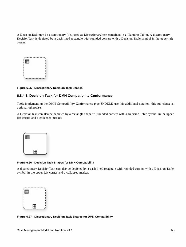
A DecisionTask may be discretionary (i.e., used as DiscretionaryItem contained in a Planning Table). A discretionary DecisionTask is depicted by a dash lined rectangle with rounded corners with a Decision Table symbol in the upper left corner.
Figure 6.25 - Discretionary Decision Task Shapes
6.8.4.1 Decision Task for DMN Compatibility Conformance
Tools implementing the DMN Compatibility Conformance type SHOULD use this additional notation: this sub clause is optional otherwise.
A DecisionTask can also be depicted by a rectangle shape wit rounded corners with a Decision Table symbol in the upper left corner and a collapsed marker.
Figure 6.26 - Decision Task Shapes for DMN Compatibility
A discretionary DecisionTask can also be depicted by a dash-lined rectangle with rounded corners with a Decision Table symbol in the upper left corner and a collapsed marker.
Figure 6.27 - Discretionary Decision Task Shapes for DMN Compatibility
Case Management Model and Notation, v1.1 65
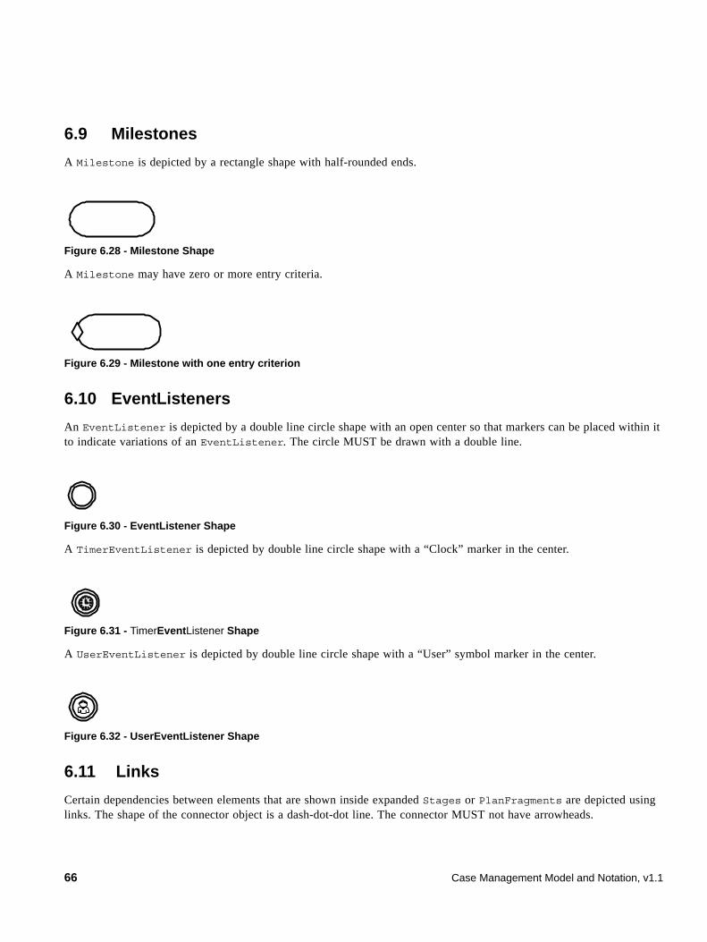
6.9 Milestones
A Milestone is depicted by a rectangle shape with half-rounded ends.
Figure 6.28 - Milestone Shape
A Milestone may have zero or more entry criteria.
Figure 6.29 - Milestone with one entry criterion
6.10 EventListeners
An EventListener is depicted by a double line circle shape with an open center so that markers can be placed within it to indicate variations of an EventListener. The circle MUST be drawn with a double line.
Figure 6.30 - EventListener Shape
A TimerEventListener is depicted by double line circle shape with a “Clock” marker in the center.
Figure 6.31 - TimerEventListener Shape
A UserEventListener is depicted by double line circle shape with a “User” symbol marker in the center.
Figure 6.32 - UserEventListener Shape
6.11 Links
Certain dependencies between elements that are shown inside expanded Stages or PlanFragments are depicted using links. The shape of the connector object is a dash-dot-dot line. The connector MUST not have arrowheads.
66 Case Management Model and Notation, v1.1
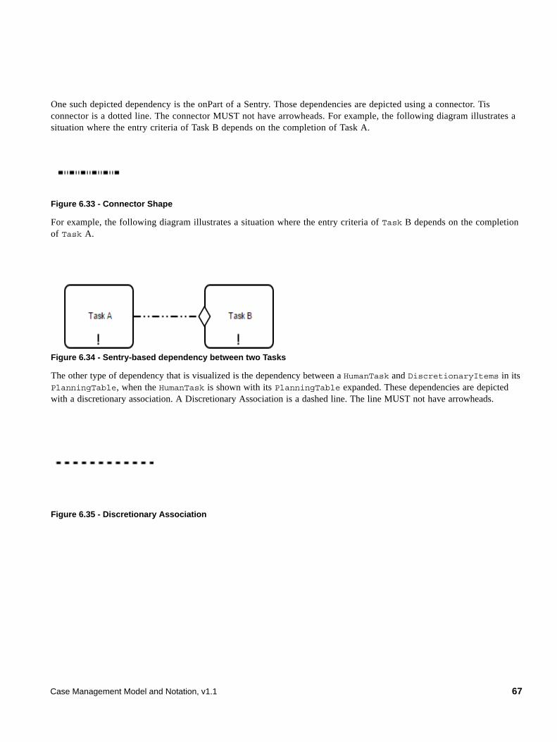
One such depicted dependency is the onPart of a Sentry. Those dependencies are depicted using a connector. Tis connector is a dotted line. The connector MUST not have arrowheads. For example, the following diagram illustrates a situation where the entry criteria of Task B depends on the completion of Task A.
Figure 6.33 - Connector Shape
For example, the following diagram illustrates a situation where the entry criteria of Task B depends on the completion of Task A.
Figure 6.34 - Sentry-based dependency between two Tasks
The other type of dependency that is visualized is the dependency between a HumanTask and DiscretionaryItems in its PlanningTable, when the HumanTask is shown with its PlanningTable expanded. These dependencies are depicted with a discretionary association. A Discretionary Association is a dashed line. The line MUST not have arrowheads.
Figure 6.35 - Discretionary Association
Case Management Model and Notation, v1.1 67
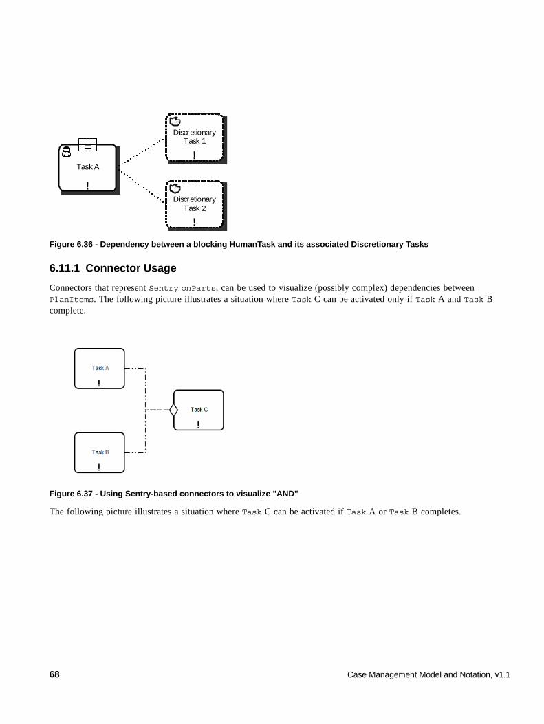
Figure 6.36 - Dependency between a blocking HumanTask and its associated Discretionary Tasks
6.11.1 Connector Usage
Connectors that represent Sentry onParts, can be used to visualize (possibly complex) dependencies between PlanItems. The following picture illustrates a situation where Task C can be activated only if Task A and Task B complete.
Figure 6.37 - Using Sentry-based connectors to visualize "AND"
The following picture illustrates a situation where Task C can be activated if Task A or Task B completes.
!
Task A!
Discretionary Task 1
!
Discretionary Task 2
68 Case Management Model and Notation, v1.1
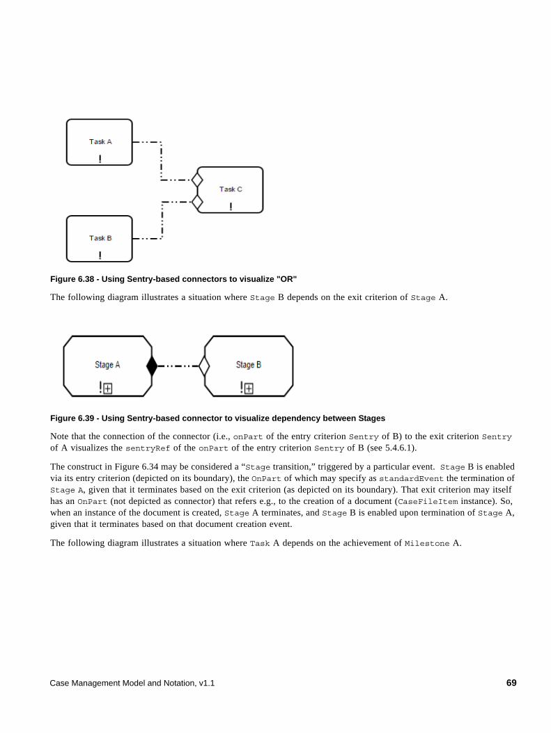
Figure 6.38 - Using Sentry-based connectors to visualize "OR"
The following diagram illustrates a situation where Stage B depends on the exit criterion of Stage A.
Figure 6.39 - Using Sentry-based connector to visualize dependency between Stages
Note that the connection of the connector (i.e., onPart of the entry criterion Sentry of B) to the exit criterion Sentry of A visualizes the sentryRef of the onPart of the entry criterion Sentry of B (see 5.4.6.1).
The construct in Figure 6.34 may be considered a “Stage transition,” triggered by a particular event. Stage B is enabled via its entry criterion (depicted on its boundary), the OnPart of which may specify as standardEvent the termination of Stage A, given that it terminates based on the exit criterion (as depicted on its boundary). That exit criterion may itself has an OnPart (not depicted as connector) that refers e.g., to the creation of a document (CaseFileItem instance). So, when an instance of the document is created, Stage A terminates, and Stage B is enabled upon termination of Stage A, given that it terminates based on that document creation event.
The following diagram illustrates a situation where Task A depends on the achievement of Milestone A.
Case Management Model and Notation, v1.1 69
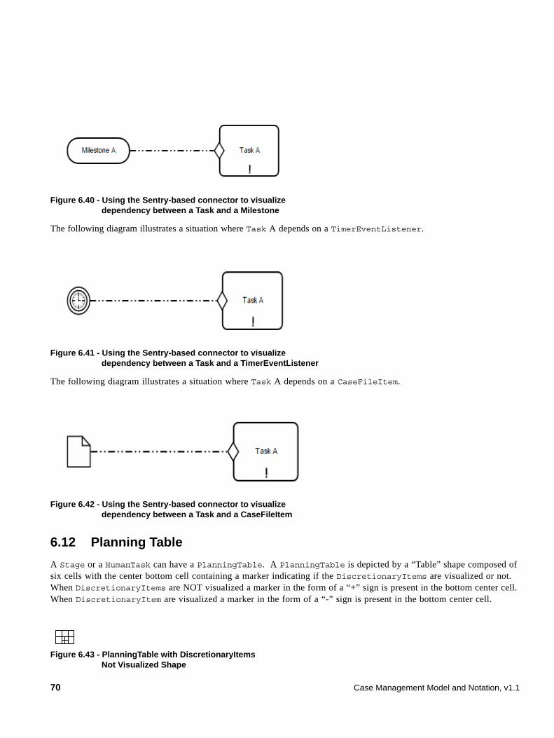
Figure 6.40 - Using the Sentry-based connector to visualize dependency between a Task and a Milestone
The following diagram illustrates a situation where Task A depends on a TimerEventListener.
Figure 6.41 - Using the Sentry-based connector to visualize dependency between a Task and a TimerEventListener
The following diagram illustrates a situation where Task A depends on a CaseFileItem.
Figure 6.42 - Using the Sentry-based connector to visualize dependency between a Task and a CaseFileItem
6.12 Planning Table
A Stage or a HumanTask can have a PlanningTable. A PlanningTable is depicted by a “Table” shape composed of six cells with the center bottom cell containing a marker indicating if the DiscretionaryItems are visualized or not. When DiscretionaryItems are NOT visualized a marker in the form of a “+” sign is present in the bottom center cell. When DiscretionaryItem are visualized a marker in the form of a “-” sign is present in the bottom center cell.
Figure 6.43 - PlanningTable with DiscretionaryItems Not Visualized Shape
70 Case Management Model and Notation, v1.1
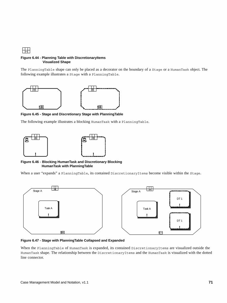
Figure 6.44 - Planning Table with DiscretionaryItems Visualized Shape
The PlanningTable shape can only be placed as a decorator on the boundary of a Stage or a HumanTask object. The following example illustrates a Stage with a PlanningTable.
Figure 6.45 - Stage and Discretionary Stage with PlanningTable
The following example illustrates a blocking HumanTask with a PlanningTable.
Figure 6.46 - Blocking HumanTask and Discretionary Blocking HumanTask with PlanningTable
When a user “expands” a PlanningTable, its contained DiscretionaryItems become visible within the Stage.
Figure 6.47 - Stage with PlanningTable Collapsed and Expanded
When the PlanningTable of HumanTask is expanded, its contained DiscretionaryItems are visualized outside the HumanTask shape. The relationship between the DiscretionaryItems and the HumanTask is visualized with the dotted line connector.
! !
! !
!
Stage A
!
Task A!
DT 1
!
DT 1
!
Stage A
!
Task A
Case Management Model and Notation, v1.1 71
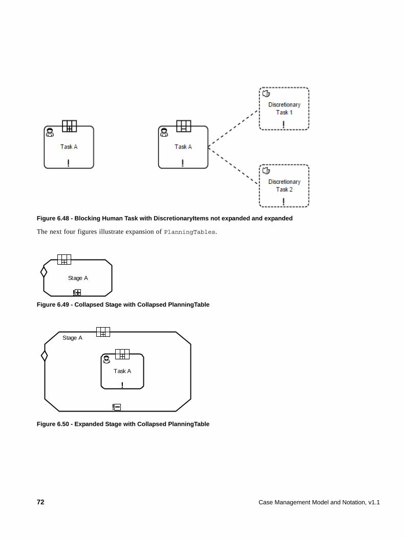
Figure 6.48 - Blocking Human Task with DiscretionaryItems not expanded and expanded
The next four figures illustrate expansion of PlanningTables.
Figure 6.49 - Collapsed Stage with Collapsed PlanningTable
Figure 6.50 - Expanded Stage with Collapsed PlanningTable
!
Stage A
!
Stage A
!
Task A
72 Case Management Model and Notation, v1.1
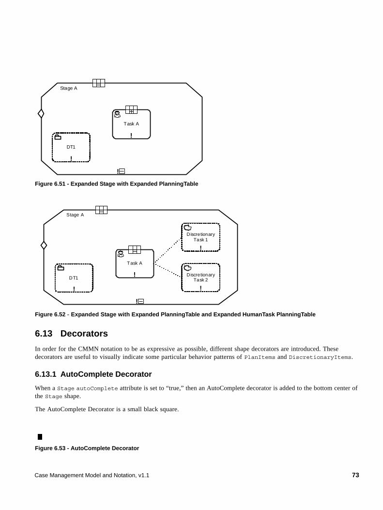
Figure 6.51 - Expanded Stage with Expanded PlanningTable
Figure 6.52 - Expanded Stage with Expanded PlanningTable and Expanded HumanTask PlanningTable
6.13 Decorators
In order for the CMMN notation to be as expressive as possible, different shape decorators are introduced. These decorators are useful to visually indicate some particular behavior patterns of PlanItems and DiscretionaryItems.
6.13.1 AutoComplete Decorator
When a Stage autoComplete attribute is set to “true,” then an AutoComplete decorator is added to the bottom center of the Stage shape.
The AutoComplete Decorator is a small black square.
Figure 6.53 - AutoComplete Decorator
!
Stage A
!
Task A
!
DT1
!
Stage A
!
DT1!
Task A
!
Discretionary Task 1
!
Discretionary Task 2
Case Management Model and Notation, v1.1 73
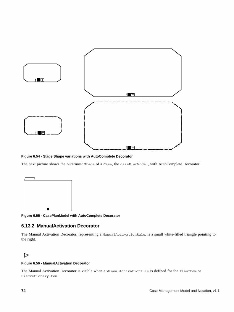
Figure 6.54 - Stage Shape variations with AutoComplete Decorator
The next picture shows the outermost Stage of a Case, the casePlanModel, with AutoComplete Decorator.
Figure 6.55 - CasePlanModel with AutoComplete Decorator
6.13.2 ManualActivation Decorator
The Manual Activation Decorator, representing a ManualActivationRule, is a small white-filled triangle pointing to the right.
Figure 6.56 - ManualActivation Decorator
The Manual Activation Decorator is visible when a ManualActivationRule is defined for the PlanItem or DiscretionaryItem.
!
!
!
!
74 Case Management Model and Notation, v1.1
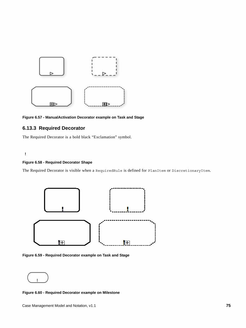
Figure 6.57 - ManualActivation Decorator example on Task and Stage
6.13.3 Required Decorator
The Required Decorator is a bold black “Exclamation” symbol.
Figure 6.58 - Required Decorator Shape
The Required Decorator is visible when a RequiredRule is defined for PlanItem or DiscretionaryItem.
Figure 6.59 - Required Decorator example on Task and Stage
Figure 6.60 - Required Decorator example on Milestone
!
Case Management Model and Notation, v1.1 75
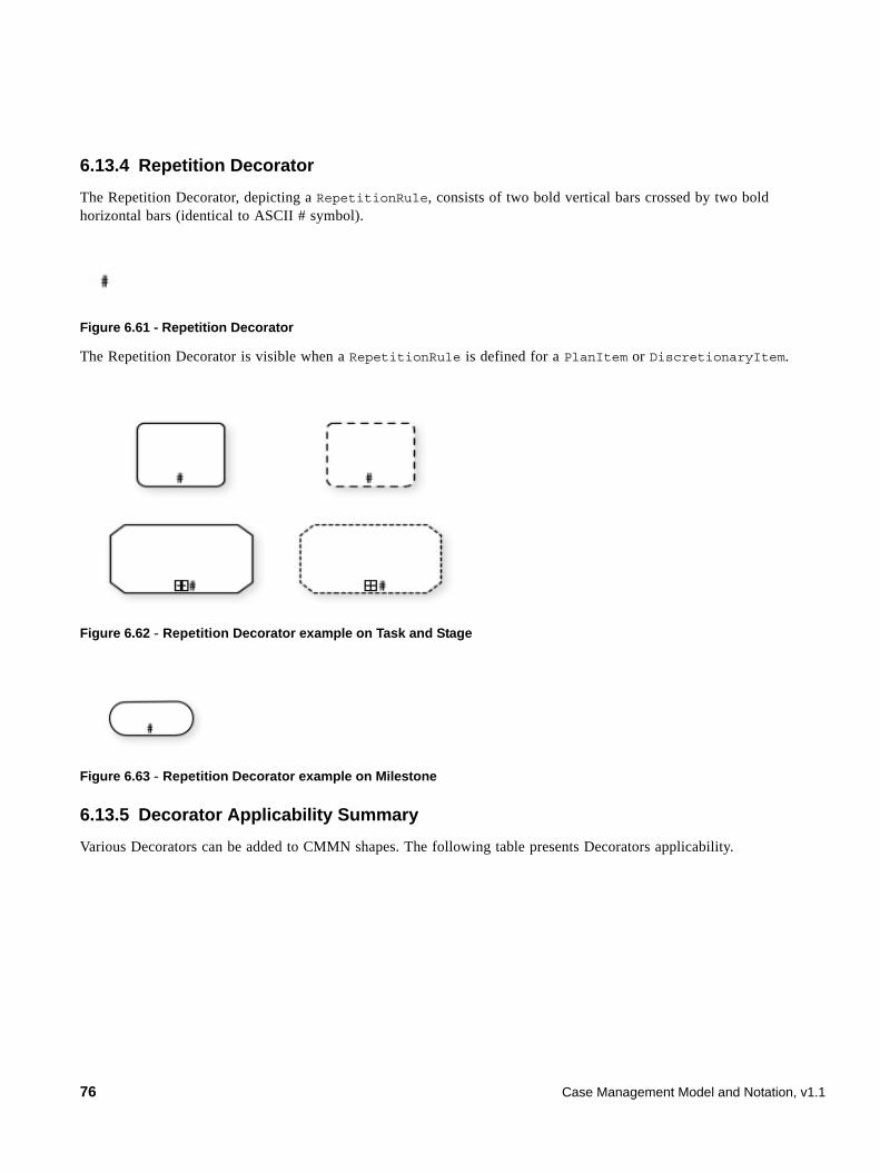
6.13.4 Repetition Decorator
The Repetition Decorator, depicting a RepetitionRule, consists of two bold vertical bars crossed by two bold horizontal bars (identical to ASCII # symbol).
Figure 6.61 - Repetition Decorator
The Repetition Decorator is visible when a RepetitionRule is defined for a PlanItem or DiscretionaryItem.
Figure 6.62 - Repetition Decorator example on Task and Stage
Figure 6.63 - Repetition Decorator example on Milestone
6.13.5 Decorator Applicability Summary
Various Decorators can be added to CMMN shapes. The following table presents Decorators applicability.
76 Case Management Model and Notation, v1.1
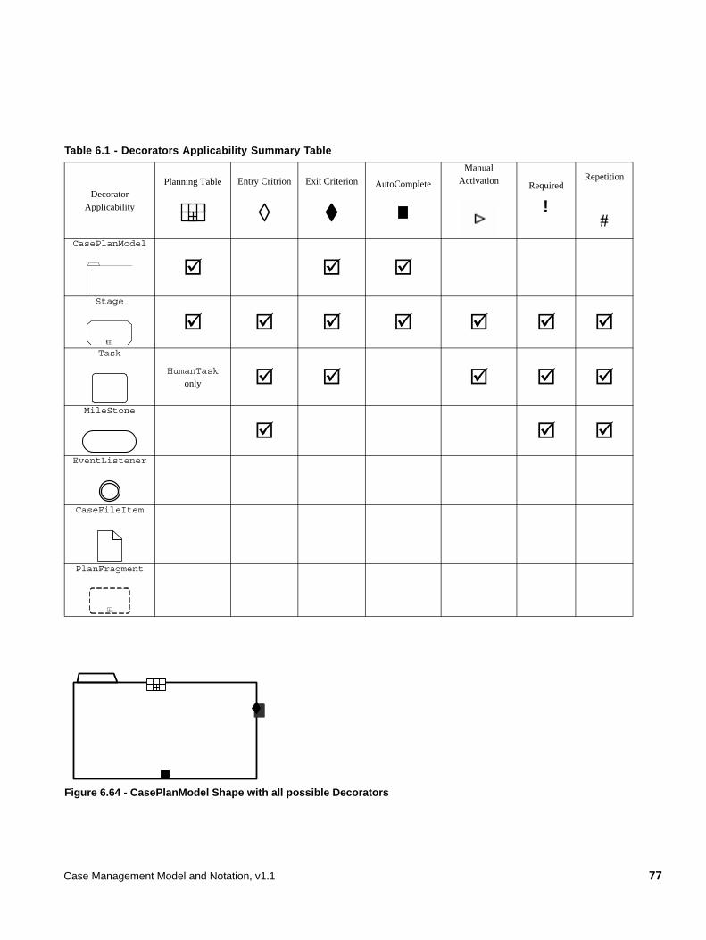
Figure 6.64 - CasePlanModel Shape with all possible Decorators
Table 6.1 - Decorators Applicability Summary Table
Decorator Applicability
Planning Table Entry Critrion Exit Criterion AutoComplete
Manual Activation Required
Repetition
#CasePlanModel
Stage
Task
HumanTask only
MileStone
EventListener
CaseFileItem
PlanFragment
!
!
Case Management Model and Notation, v1.1 77
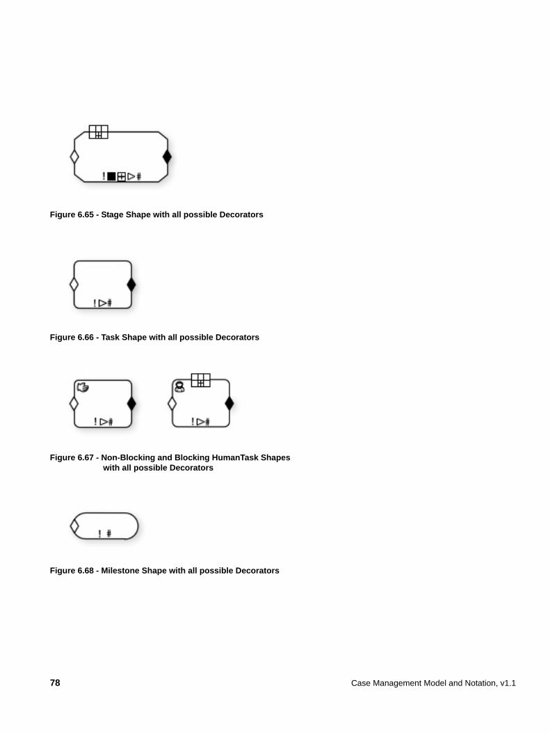
Figure 6.65 - Stage Shape with all possible Decorators
Figure 6.66 - Task Shape with all possible Decorators
Figure 6.67 - Non-Blocking and Blocking HumanTask Shapes with all possible Decorators
Figure 6.68 - Milestone Shape with all possible Decorators
78 Case Management Model and Notation, v1.1
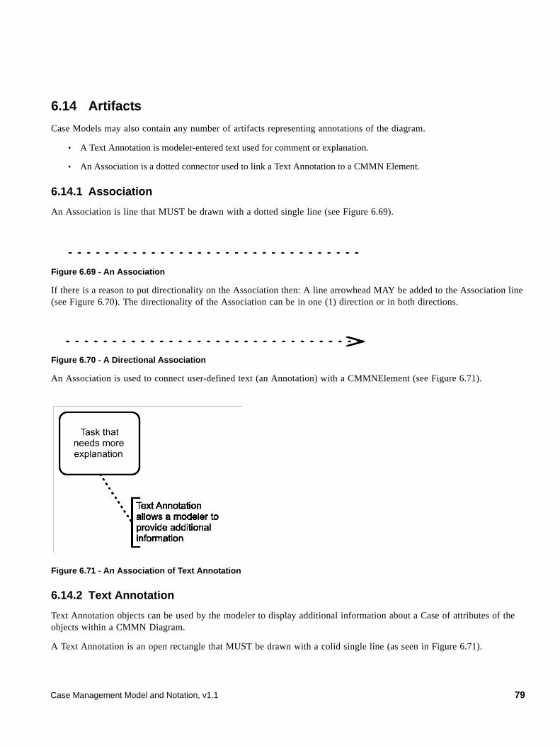
6.14 Artifacts
Case Models may also contain any number of artifacts representing annotations of the diagram.
• A Text Annotation is modeler-entered text used for comment or explanation.
• An Association is a dotted connector used to link a Text Annotation to a CMMN Element.
6.14.1 Association
An Association is line that MUST be drawn with a dotted single line (see Figure 6.69).
Figure 6.69 - An Association
If there is a reason to put directionality on the Association then: A line arrowhead MAY be added to the Association line (see Figure 6.70). The directionality of the Association can be in one (1) direction or in both directions.
Figure 6.70 - A Directional Association
An Association is used to connect user-defined text (an Annotation) with a CMMNElement (see Figure 6.71).
Figure 6.71 - An Association of Text Annotation
6.14.2 Text Annotation
Text Annotation objects can be used by the modeler to display additional information about a Case of attributes of the objects within a CMMN Diagram.
A Text Annotation is an open rectangle that MUST be drawn with a colid single line (as seen in Figure 6.71).
Case Management Model and Notation, v1.1 79
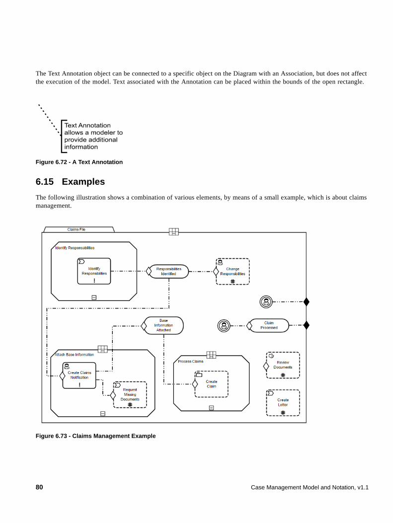
The Text Annotation object can be connected to a specific object on the Diagram with an Association, but does not affect the execution of the model. Text associated with the Annotation can be placed within the bounds of the open rectangle.
Figure 6.72 - A Text Annotation
6.15 Examples
The following illustration shows a combination of various elements, by means of a small example, which is about claims management.
Figure 6.73 - Claims Management Example
80 Case Management Model and Notation, v1.1
7 CMMN Diagram Interchange (DMMN DI)
7.1 Scope
This chapter specifies the meta-model and schema for CMMN 1.1 Diagram Interchange (CMMN DI). The CMMN DI is meant to facilitate interchange of CMMN diagrams between tools rather than being used for internal diagram representation by the tools. The simplest interchange approach to ensure the unambiguous rendering of a CMMN diagram was chosen for CMMN DI. As such, CMMN DI does not aim to preserve or interchange any “tool smarts” between the source and target tools (e.g., layout smarts, efficient styling, etc.).
CMMN DI does not ascertain that the CMMN diagram is syntactically or semantically correct.
7.2 Diagram Definition and Interchange
The CMMN DI meta-model, similar to the CMMN abstract syntax meta-model, is defined as a MOF-based meta-model. As such, its instances can be serialized and interchanged using XMI. CMMN DI is also defined by an XML schema. Thus its instances can also be serialized and interchanged using XML.
Both, CMMN DI meta-model and schema are harmonized with the OMG Diagram Definition (DD) standard version 1.1. The referenced DD contains two main parts: the Diagram Commons (DC) and the Diagram Interchange (DI). The DC defines common types like bounds and points, while the DI provides a framework for defining domain specific diagram models. As a domain specific DI, CMMN DI defines a few new meta-model classes that derive from the abstract classes from DI.
The focus of CMMN DI is the interchange of laid out shapes and edges that constitute a CMMN diagram. Each shape and edge references a particular CMMN model element. The referenced CMMN model elements are all part of the actual CMMN model. As such, CMMN DI is meant to only contain information that is neither present, nor derivable, from the CMMN model whenever possible. Simply put, to render a CMMN diagram both the CMMN DI instance(s) and the referenced CMMN model are REQUIRED.
From the CMMN DI perspective, a CMMN diagram is a particular snapshot of a CMMN model at a certain point in time. Multiple CMMN diagrams can be exchanged referencing model elements from the same CMMN model. Each diagram may provide an incomplete or partial depiction of the content of the CMMN model. As described in Chapter 9, a CMMN model package consists of one or more files. Each file may contain any number of CMMN diagrams. The exporting tool is free to decide how many diagrams are exported and the importing tool is free to decide if and how to present the contained diagrams to the user.
7.3 How to read this chapter
Sub clause 7.4 describes in details the meta-model used to keep the layout and the look of CMMN Diagrams. Sub clause 7.5 presents in tables a library of the CMMN element depictions and an unambiguous resolution between a referenced CMMN model element and its depiction.
Case Management Model and Notation, v1.1 81
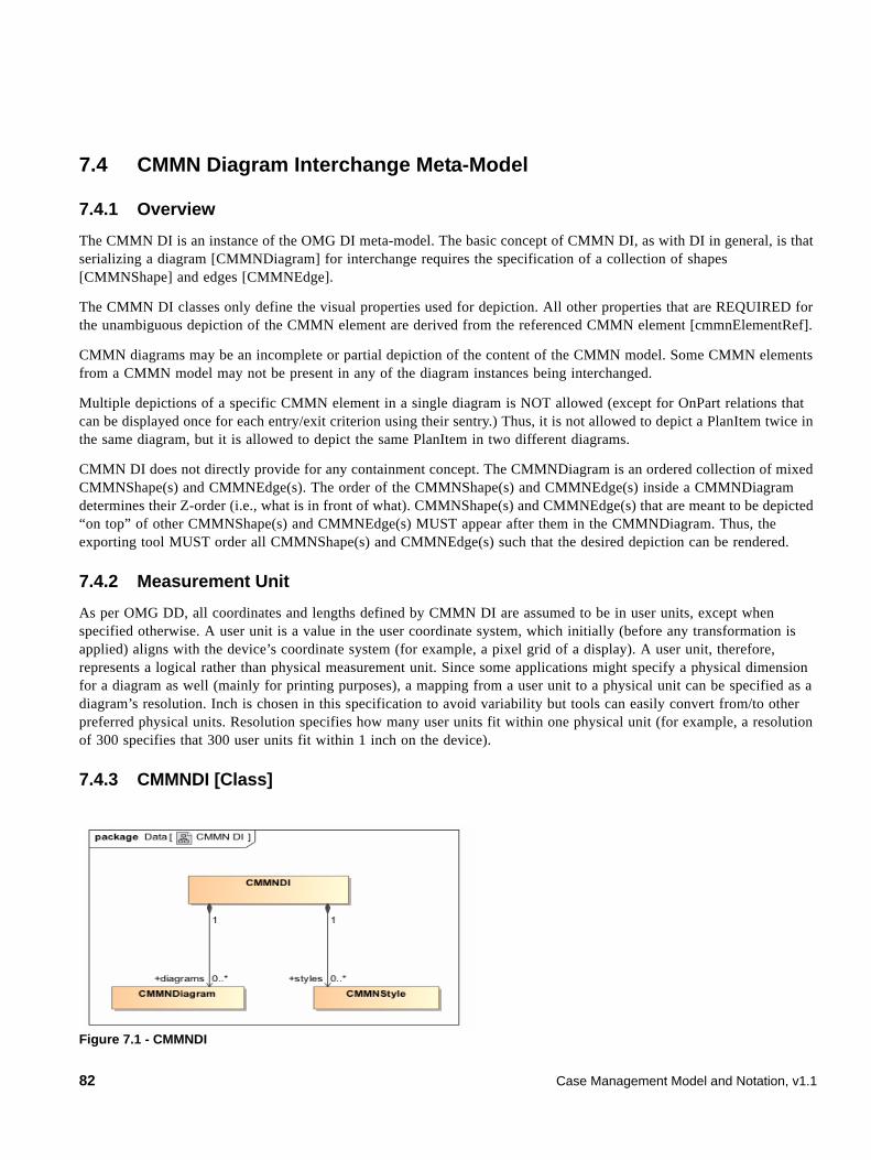
7.4 CMMN Diagram Interchange Meta-Model
7.4.1 Overview
The CMMN DI is an instance of the OMG DI meta-model. The basic concept of CMMN DI, as with DI in general, is that serializing a diagram [CMMNDiagram] for interchange requires the specification of a collection of shapes [CMMNShape] and edges [CMMNEdge].
The CMMN DI classes only define the visual properties used for depiction. All other properties that are REQUIRED for the unambiguous depiction of the CMMN element are derived from the referenced CMMN element [cmmnElementRef].
CMMN diagrams may be an incomplete or partial depiction of the content of the CMMN model. Some CMMN elements from a CMMN model may not be present in any of the diagram instances being interchanged.
Multiple depictions of a specific CMMN element in a single diagram is NOT allowed (except for OnPart relations that can be displayed once for each entry/exit criterion using their sentry.) Thus, it is not allowed to depict a PlanItem twice in the same diagram, but it is allowed to depict the same PlanItem in two different diagrams.
CMMN DI does not directly provide for any containment concept. The CMMNDiagram is an ordered collection of mixed CMMNShape(s) and CMMNEdge(s). The order of the CMMNShape(s) and CMMNEdge(s) inside a CMMNDiagram determines their Z-order (i.e., what is in front of what). CMMNShape(s) and CMMNEdge(s) that are meant to be depicted “on top” of other CMMNShape(s) and CMMNEdge(s) MUST appear after them in the CMMNDiagram. Thus, the exporting tool MUST order all CMMNShape(s) and CMMNEdge(s) such that the desired depiction can be rendered.
7.4.2 Measurement Unit
As per OMG DD, all coordinates and lengths defined by CMMN DI are assumed to be in user units, except when specified otherwise. A user unit is a value in the user coordinate system, which initially (before any transformation is applied) aligns with the device’s coordinate system (for example, a pixel grid of a display). A user unit, therefore, represents a logical rather than physical measurement unit. Since some applications might specify a physical dimension for a diagram as well (mainly for printing purposes), a mapping from a user unit to a physical unit can be specified as a diagram’s resolution. Inch is chosen in this specification to avoid variability but tools can easily convert from/to other preferred physical units. Resolution specifies how many user units fit within one physical unit (for example, a resolution of 300 specifies that 300 user units fit within 1 inch on the device).
7.4.3 CMMNDI [Class]
Figure 7.1 - CMMNDI
82 Case Management Model and Notation, v1.1
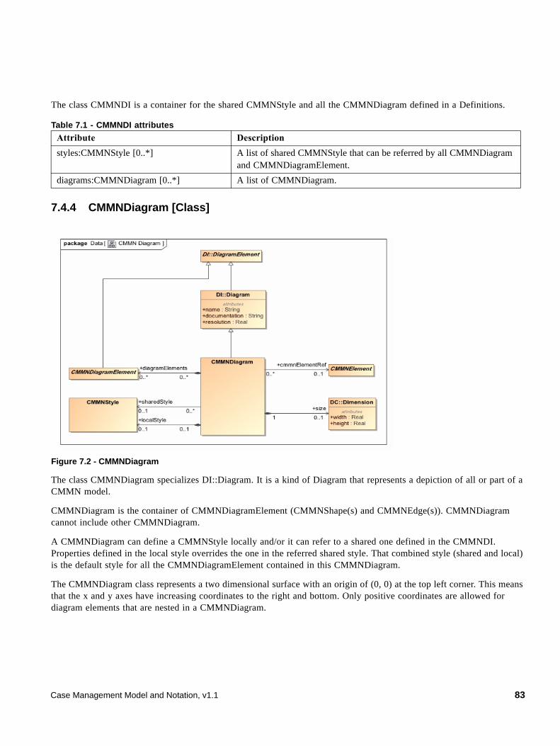
The class CMMNDI is a container for the shared CMMNStyle and all the CMMNDiagram defined in a Definitions.
7.4.4 CMMNDiagram [Class]
Figure 7.2 - CMMNDiagram
The class CMMNDiagram specializes DI::Diagram. It is a kind of Diagram that represents a depiction of all or part of a CMMN model.
CMMNDiagram is the container of CMMNDiagramElement (CMMNShape(s) and CMMNEdge(s)). CMMNDiagram cannot include other CMMNDiagram.
A CMMNDiagram can define a CMMNStyle locally and/or it can refer to a shared one defined in the CMMNDI. Properties defined in the local style overrides the one in the referred shared style. That combined style (shared and local) is the default style for all the CMMNDiagramElement contained in this CMMNDiagram.
The CMMNDiagram class represents a two dimensional surface with an origin of (0, 0) at the top left corner. This means that the x and y axes have increasing coordinates to the right and bottom. Only positive coordinates are allowed for diagram elements that are nested in a CMMNDiagram.
Table 7.1 - CMMNDI attributes
Attribute Description
styles:CMMNStyle [0..*] A list of shared CMMNStyle that can be referred by all CMMNDiagram and CMMNDiagramElement.
diagrams:CMMNDiagram [0..*] A list of CMMNDiagram.
Case Management Model and Notation, v1.1 83
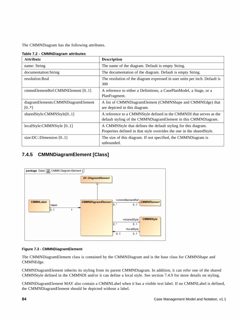
The CMMNDiagram has the following attributes.
7.4.5 CMMNDiagramElement [Class]
Figure 7.3 - CMMNDiagramElement
The CMMNDiagramElement class is contained by the CMMNDiagram and is the base class for CMMNShape and CMMNEdge.
CMMNDiagramElement inherits its styling from its parent CMMNDiagram. In addition, it can refer one of the shared CMMNStyle defined in the CMMNDI and/or it can define a local style. See section 7.4.9 for more details on styling.
CMMNDiagramElement MAY also contain a CMMNLabel when it has a visible text label. If no CMMNLabel is defined, the CMMNDiagramElement should be depicted without a label.
Table 7.2 - CMMNDiagram attributes
Attribute Description
name: String The name of the diagram. Default is empty String.
documentation:String The documentation of the diagram. Default is empty String.
resolution:Real The resolution of the diagram expressed in user units per inch. Default is 300
cmmnElementRef:CMMNElement [0..1] A reference to either a Definitions, a CasePlanModel, a Stage, or a PlanFragment.
diagramElements:CMMNDiagramElement [0..*]
A list of CMMNDiagramElement (CMMNShape and CMMNEdge) that are depicted in this diagram.
sharedStyle:CMMNStyle[0..1] A reference to a CMMNStyle defined in the CMMNDI that serves as the default styling of the CMMNDiagramElement in this CMMNDiagram.
localStyle:CMMNStyle [0..1] A CMMNStyle that defines the default styling for this diagram. Properties defined in that style overrides the one in the sharedStyle.
size:DC::Dimension [0..1] The size of this diagram. If not specified, the CMMNDiagram is unbounded.
84 Case Management Model and Notation, v1.1
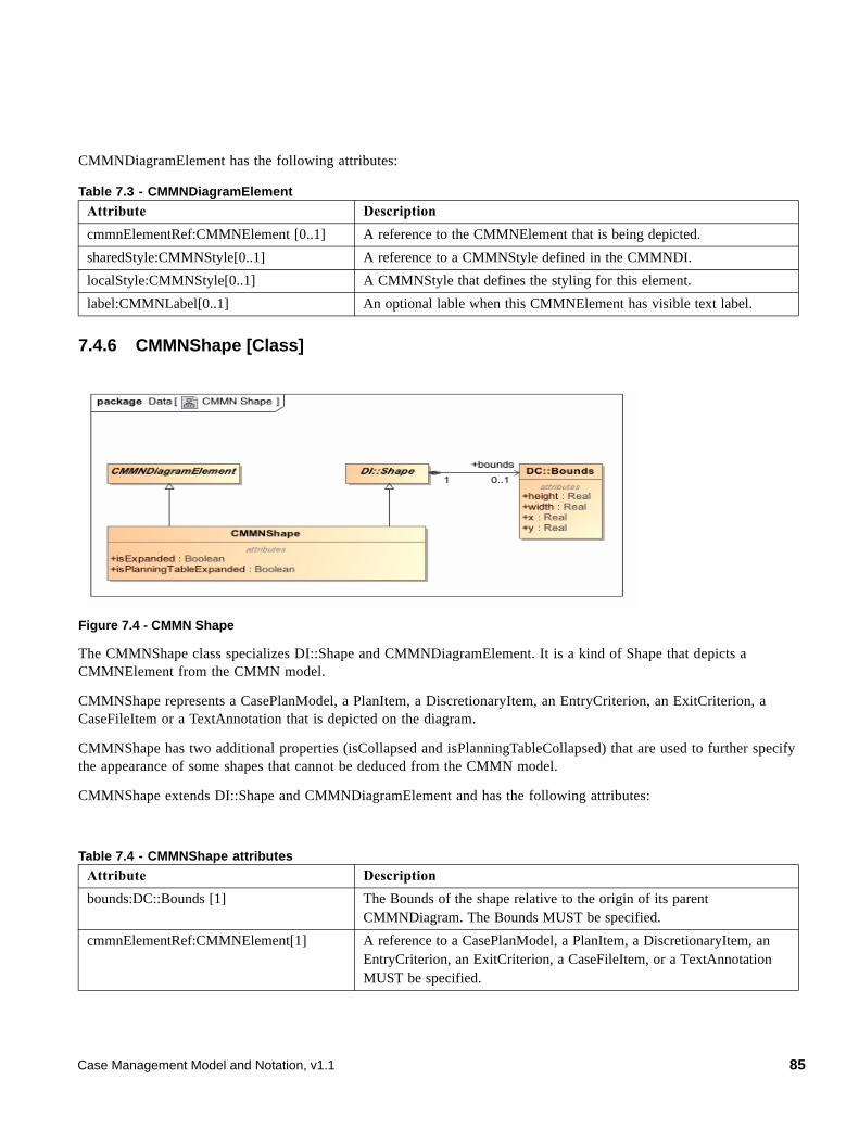
CMMNDiagramElement has the following attributes:
7.4.6 CMMNShape [Class]
Figure 7.4 - CMMN Shape
The CMMNShape class specializes DI::Shape and CMMNDiagramElement. It is a kind of Shape that depicts a CMMNElement from the CMMN model.
CMMNShape represents a CasePlanModel, a PlanItem, a DiscretionaryItem, an EntryCriterion, an ExitCriterion, a CaseFileItem or a TextAnnotation that is depicted on the diagram.
CMMNShape has two additional properties (isCollapsed and isPlanningTableCollapsed) that are used to further specify the appearance of some shapes that cannot be deduced from the CMMN model.
CMMNShape extends DI::Shape and CMMNDiagramElement and has the following attributes:
Table 7.3 - CMMNDiagramElement
Attribute Description
cmmnElementRef:CMMNElement [0..1] A reference to the CMMNElement that is being depicted.
sharedStyle:CMMNStyle[0..1] A reference to a CMMNStyle defined in the CMMNDI.
localStyle:CMMNStyle[0..1] A CMMNStyle that defines the styling for this element.
label:CMMNLabel[0..1] An optional lable when this CMMNElement has visible text label.
Table 7.4 - CMMNShape attributes
Attribute Description
bounds:DC::Bounds [1] The Bounds of the shape relative to the origin of its parent CMMNDiagram. The Bounds MUST be specified.
cmmnElementRef:CMMNElement[1] A reference to a CasePlanModel, a PlanItem, a DiscretionaryItem, an EntryCriterion, an ExitCriterion, a CaseFileItem, or a TextAnnotation MUST be specified.
Case Management Model and Notation, v1.1 85
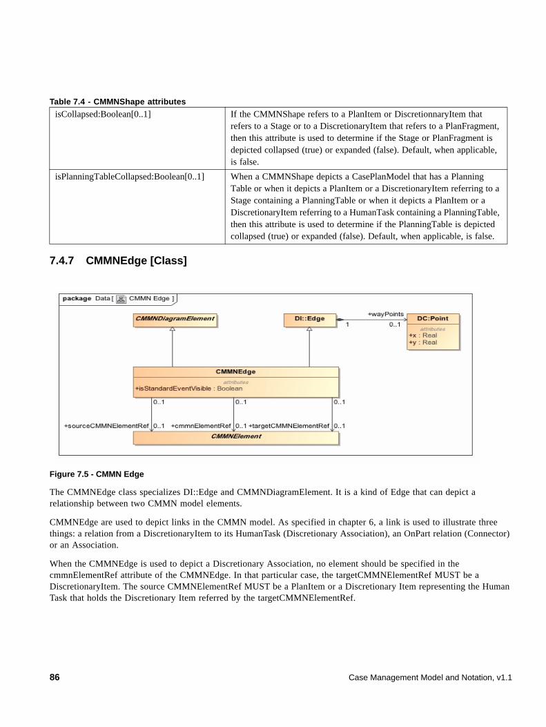
7.4.7 CMMNEdge [Class]
Figure 7.5 - CMMN Edge
The CMMNEdge class specializes DI::Edge and CMMNDiagramElement. It is a kind of Edge that can depict a relationship between two CMMN model elements.
CMMNEdge are used to depict links in the CMMN model. As specified in chapter 6, a link is used to illustrate three things: a relation from a DiscretionaryItem to its HumanTask (Discretionary Association), an OnPart relation (Connector) or an Association.
When the CMMNEdge is used to depict a Discretionary Association, no element should be specified in the cmmnElementRef attribute of the CMMNEdge. In that particular case, the targetCMMNElementRef MUST be a DiscretionaryItem. The source CMMNElementRef MUST be a PlanItem or a Discretionary Item representing the Human Task that holds the Discretionary Item referred by the targetCMMNElementRef.
isCollapsed:Boolean[0..1] If the CMMNShape refers to a PlanItem or DiscretionnaryItem that refers to a Stage or to a DiscretionaryItem that refers to a PlanFragment, then this attribute is used to determine if the Stage or PlanFragment is depicted collapsed (true) or expanded (false). Default, when applicable, is false.
isPlanningTableCollapsed:Boolean[0..1] When a CMMNShape depicts a CasePlanModel that has a Planning Table or when it depicts a PlanItem or a DiscretionaryItem referring to a Stage containing a PlanningTable or when it depicts a PlanItem or a DiscretionaryItem referring to a HumanTask containing a PlanningTable, then this attribute is used to determine if the PlanningTable is depicted collapsed (true) or expanded (false). Default, when applicable, is false.
Table 7.4 - CMMNShape attributes
86 Case Management Model and Notation, v1.1
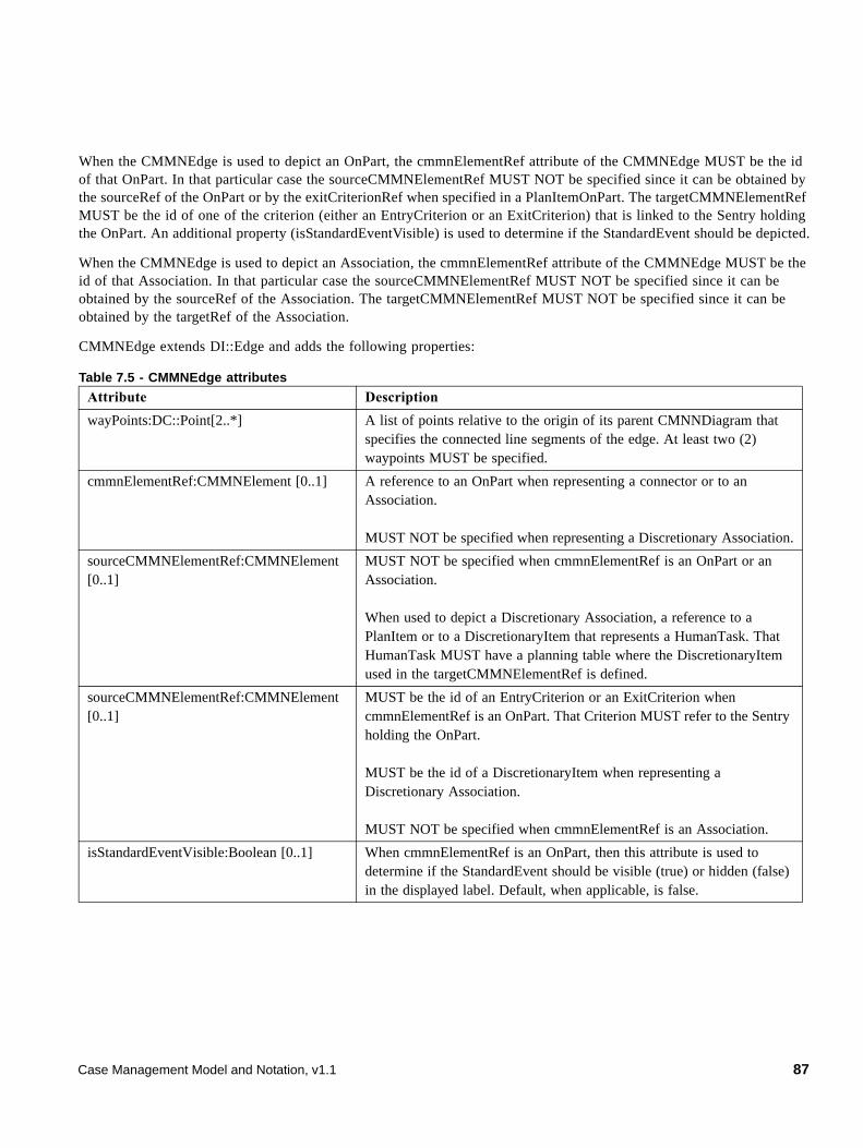
When the CMMNEdge is used to depict an OnPart, the cmmnElementRef attribute of the CMMNEdge MUST be the id of that OnPart. In that particular case the sourceCMMNElementRef MUST NOT be specified since it can be obtained by the sourceRef of the OnPart or by the exitCriterionRef when specified in a PlanItemOnPart. The targetCMMNElementRef MUST be the id of one of the criterion (either an EntryCriterion or an ExitCriterion) that is linked to the Sentry holding the OnPart. An additional property (isStandardEventVisible) is used to determine if the StandardEvent should be depicted.
When the CMMNEdge is used to depict an Association, the cmmnElementRef attribute of the CMMNEdge MUST be the id of that Association. In that particular case the sourceCMMNElementRef MUST NOT be specified since it can be obtained by the sourceRef of the Association. The targetCMMNElementRef MUST NOT be specified since it can be obtained by the targetRef of the Association.
CMMNEdge extends DI::Edge and adds the following properties:
Table 7.5 - CMMNEdge attributes
Attribute Description
wayPoints:DC::Point[2..*] A list of points relative to the origin of its parent CMNNDiagram that specifies the connected line segments of the edge. At least two (2) waypoints MUST be specified.
cmmnElementRef:CMMNElement [0..1] A reference to an OnPart when representing a connector or to an Association.
MUST NOT be specified when representing a Discretionary Association.
sourceCMMNElementRef:CMMNElement [0..1]
MUST NOT be specified when cmmnElementRef is an OnPart or an Association.
When used to depict a Discretionary Association, a reference to a PlanItem or to a DiscretionaryItem that represents a HumanTask. That HumanTask MUST have a planning table where the DiscretionaryItem used in the targetCMMNElementRef is defined.
sourceCMMNElementRef:CMMNElement [0..1]
MUST be the id of an EntryCriterion or an ExitCriterion when cmmnElementRef is an OnPart. That Criterion MUST refer to the Sentry holding the OnPart.
MUST be the id of a DiscretionaryItem when representing a Discretionary Association.
MUST NOT be specified when cmmnElementRef is an Association.
isStandardEventVisible:Boolean [0..1] When cmmnElementRef is an OnPart, then this attribute is used to determine if the StandardEvent should be visible (true) or hidden (false) in the displayed label. Default, when applicable, is false.
Case Management Model and Notation, v1.1 87
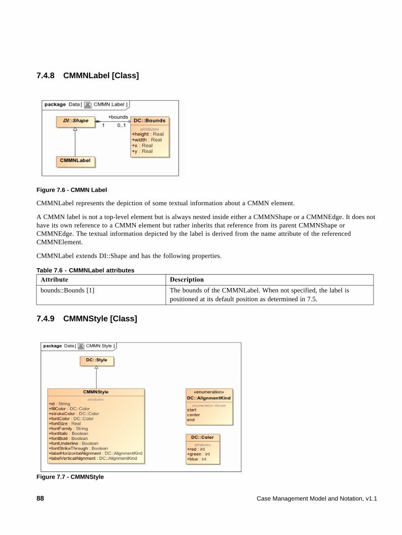
7.4.8 CMMNLabel [Class]
Figure 7.6 - CMMN Label
CMMNLabel represents the depiction of some textual information about a CMMN element.
A CMMN label is not a top-level element but is always nested inside either a CMMNShape or a CMMNEdge. It does not have its own reference to a CMMN element but rather inherits that reference from its parent CMMNShape or CMMNEdge. The textual information depicted by the label is derived from the name attribute of the referenced CMMNElement.
CMMNLabel extends DI::Shape and has the following properties.
7.4.9 CMMNStyle [Class]
Figure 7.7 - CMMNStyle
Table 7.6 - CMMNLabel attributes
Attribute Description
bounds::Bounds [1] The bounds of the CMMNLabel. When not specified, the label is positioned at its default position as determined in 7.5.
88 Case Management Model and Notation, v1.1
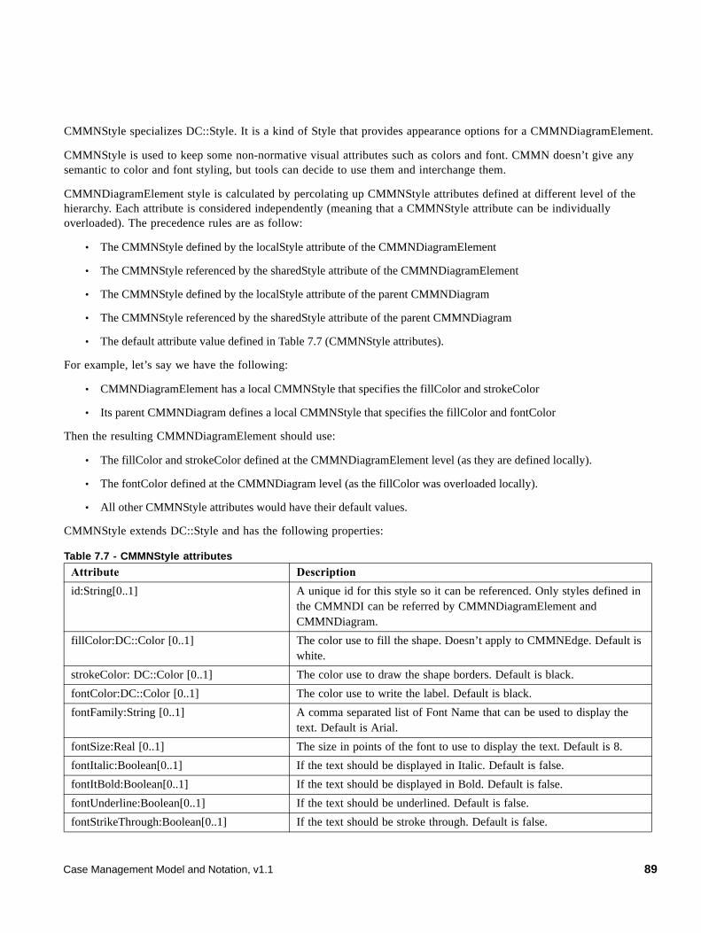
CMMNStyle specializes DC::Style. It is a kind of Style that provides appearance options for a CMMNDiagramElement.
CMMNStyle is used to keep some non-normative visual attributes such as colors and font. CMMN doesn’t give any semantic to color and font styling, but tools can decide to use them and interchange them.
CMMNDiagramElement style is calculated by percolating up CMMNStyle attributes defined at different level of the hierarchy. Each attribute is considered independently (meaning that a CMMNStyle attribute can be individually overloaded). The precedence rules are as follow:
• The CMMNStyle defined by the localStyle attribute of the CMMNDiagramElement
• The CMMNStyle referenced by the sharedStyle attribute of the CMMNDiagramElement
• The CMMNStyle defined by the localStyle attribute of the parent CMMNDiagram
• The CMMNStyle referenced by the sharedStyle attribute of the parent CMMNDiagram
• The default attribute value defined in Table 7.7 (CMMNStyle attributes).
For example, let’s say we have the following:
• CMMNDiagramElement has a local CMMNStyle that specifies the fillColor and strokeColor
• Its parent CMMNDiagram defines a local CMMNStyle that specifies the fillColor and fontColor
Then the resulting CMMNDiagramElement should use:
• The fillColor and strokeColor defined at the CMMNDiagramElement level (as they are defined locally).
• The fontColor defined at the CMMNDiagram level (as the fillColor was overloaded locally).
• All other CMMNStyle attributes would have their default values.
CMMNStyle extends DC::Style and has the following properties:
Table 7.7 - CMMNStyle attributes
Attribute Description
id:String[0..1] A unique id for this style so it can be referenced. Only styles defined in the CMMNDI can be referred by CMMNDiagramElement and CMMNDiagram.
fillColor:DC::Color [0..1] The color use to fill the shape. Doesn’t apply to CMMNEdge. Default is white.
strokeColor: DC::Color [0..1] The color use to draw the shape borders. Default is black.
fontColor:DC::Color [0..1] The color use to write the label. Default is black.
fontFamily:String [0..1] A comma separated list of Font Name that can be used to display the text. Default is Arial.
fontSize:Real [0..1] The size in points of the font to use to display the text. Default is 8.
fontItalic:Boolean[0..1] If the text should be displayed in Italic. Default is false.
fontItBold:Boolean[0..1] If the text should be displayed in Bold. Default is false.
fontUnderline:Boolean[0..1] If the text should be underlined. Default is false.
fontStrikeThrough:Boolean[0..1] If the text should be stroke through. Default is false.
Case Management Model and Notation, v1.1 89
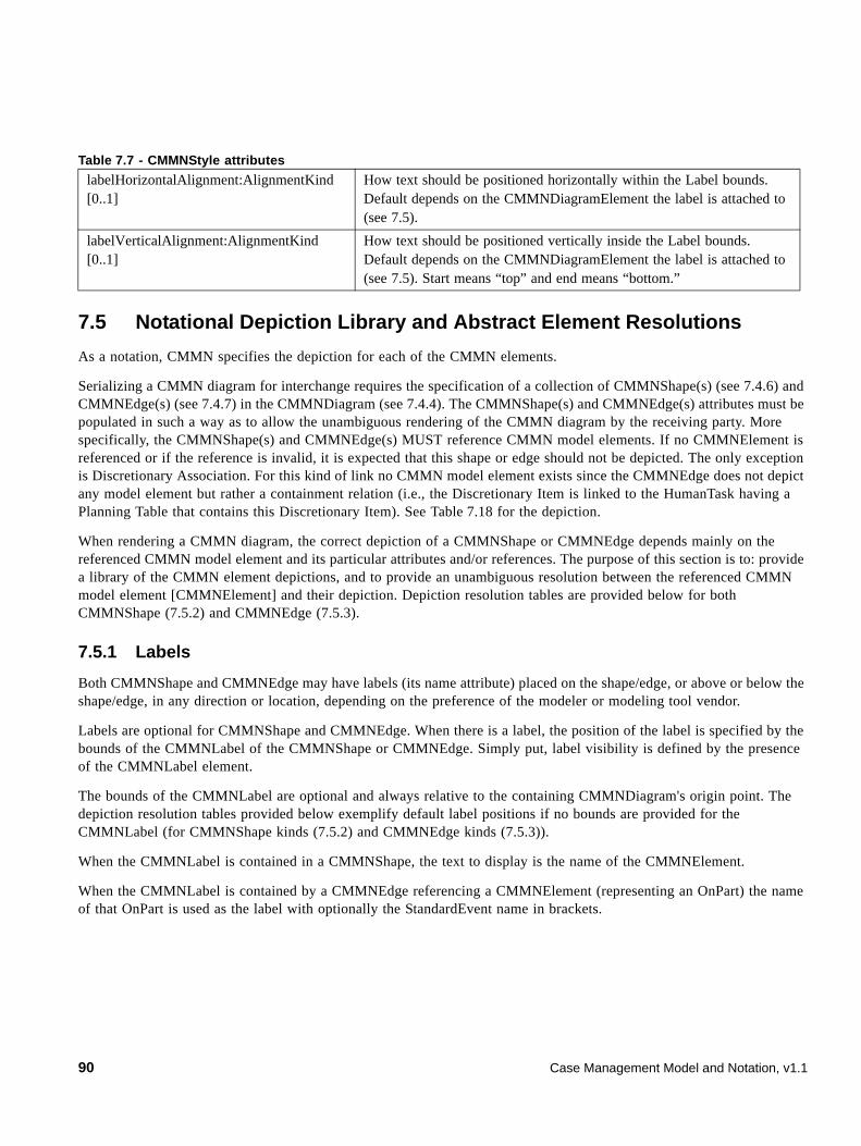
7.5 Notational Depiction Library and Abstract Element Resolutions
As a notation, CMMN specifies the depiction for each of the CMMN elements.
Serializing a CMMN diagram for interchange requires the specification of a collection of CMMNShape(s) (see 7.4.6) and CMMNEdge(s) (see 7.4.7) in the CMMNDiagram (see 7.4.4). The CMMNShape(s) and CMMNEdge(s) attributes must be populated in such a way as to allow the unambiguous rendering of the CMMN diagram by the receiving party. More specifically, the CMMNShape(s) and CMMNEdge(s) MUST reference CMMN model elements. If no CMMNElement is referenced or if the reference is invalid, it is expected that this shape or edge should not be depicted. The only exception is Discretionary Association. For this kind of link no CMMN model element exists since the CMMNEdge does not depict any model element but rather a containment relation (i.e., the Discretionary Item is linked to the HumanTask having a Planning Table that contains this Discretionary Item). See Table 7.18 for the depiction.
When rendering a CMMN diagram, the correct depiction of a CMMNShape or CMMNEdge depends mainly on the referenced CMMN model element and its particular attributes and/or references. The purpose of this section is to: provide a library of the CMMN element depictions, and to provide an unambiguous resolution between the referenced CMMN model element [CMMNElement] and their depiction. Depiction resolution tables are provided below for both CMMNShape (7.5.2) and CMMNEdge (7.5.3).
7.5.1 Labels
Both CMMNShape and CMMNEdge may have labels (its name attribute) placed on the shape/edge, or above or below the shape/edge, in any direction or location, depending on the preference of the modeler or modeling tool vendor.
Labels are optional for CMMNShape and CMMNEdge. When there is a label, the position of the label is specified by the bounds of the CMMNLabel of the CMMNShape or CMMNEdge. Simply put, label visibility is defined by the presence of the CMMNLabel element.
The bounds of the CMMNLabel are optional and always relative to the containing CMMNDiagram's origin point. The depiction resolution tables provided below exemplify default label positions if no bounds are provided for the CMMNLabel (for CMMNShape kinds (7.5.2) and CMMNEdge kinds (7.5.3)).
When the CMMNLabel is contained in a CMMNShape, the text to display is the name of the CMMNElement.
When the CMMNLabel is contained by a CMMNEdge referencing a CMMNElement (representing an OnPart) the name of that OnPart is used as the label with optionally the StandardEvent name in brackets.
labelHorizontalAlignment:AlignmentKind [0..1]
How text should be positioned horizontally within the Label bounds. Default depends on the CMMNDiagramElement the label is attached to (see 7.5).
labelVerticalAlignment:AlignmentKind [0..1]
How text should be positioned vertically inside the Label bounds. Default depends on the CMMNDiagramElement the label is attached to (see 7.5). Start means “top” and end means “bottom.”
Table 7.7 - CMMNStyle attributes
90 Case Management Model and Notation, v1.1
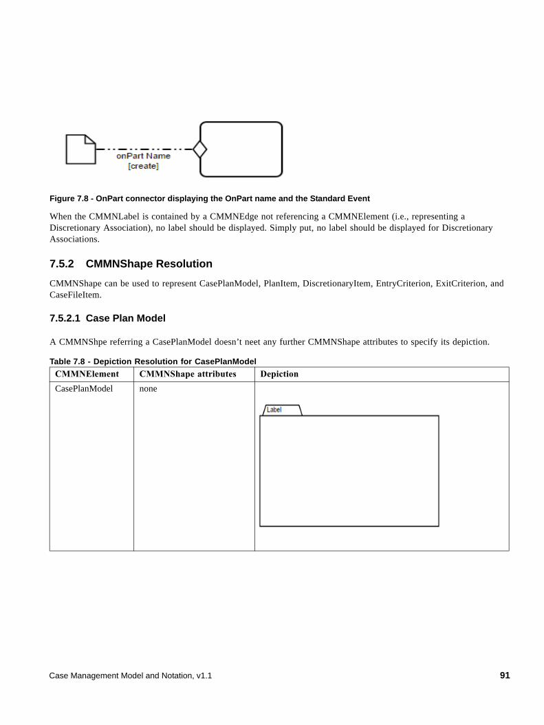
Figure 7.8 - OnPart connector displaying the OnPart name and the Standard Event
When the CMMNLabel is contained by a CMMNEdge not referencing a CMMNElement (i.e., representing a Discretionary Association), no label should be displayed. Simply put, no label should be displayed for Discretionary Associations.
7.5.2 CMMNShape Resolution
CMMNShape can be used to represent CasePlanModel, PlanItem, DiscretionaryItem, EntryCriterion, ExitCriterion, and CaseFileItem.
7.5.2.1 Case Plan Model
A CMMNShpe referring a CasePlanModel doesn’t neet any further CMMNShape attributes to specify its depiction.
Table 7.8 - Depiction Resolution for CasePlanModel
CMMNElement CMMNShape attributes Depiction
CasePlanModel none
Case Management Model and Notation, v1.1 91
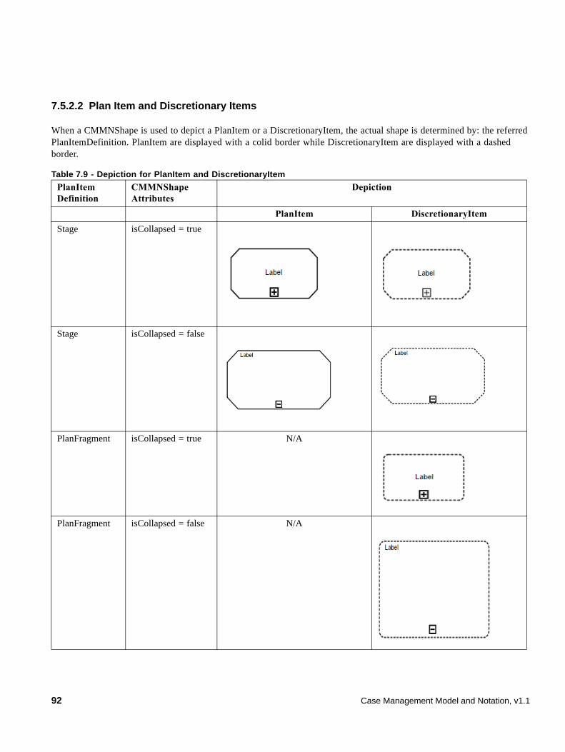
7.5.2.2 Plan Item and Discretionary Items
When a CMMNShape is used to depict a PlanItem or a DiscretionaryItem, the actual shape is determined by: the referred PlanItemDefinition. PlanItem are displayed with a colid border while DiscretionaryItem are displayed with a dashed border.
Table 7.9 - Depiction for PlanItem and DiscretionaryItem
PlanItem Definition
CMMNShape Attributes
Depiction
PlanItem DiscretionaryItem
Stage isCollapsed = true
Stage isCollapsed = false
PlanFragment isCollapsed = true N/A
PlanFragment isCollapsed = false N/A
92 Case Management Model and Notation, v1.1
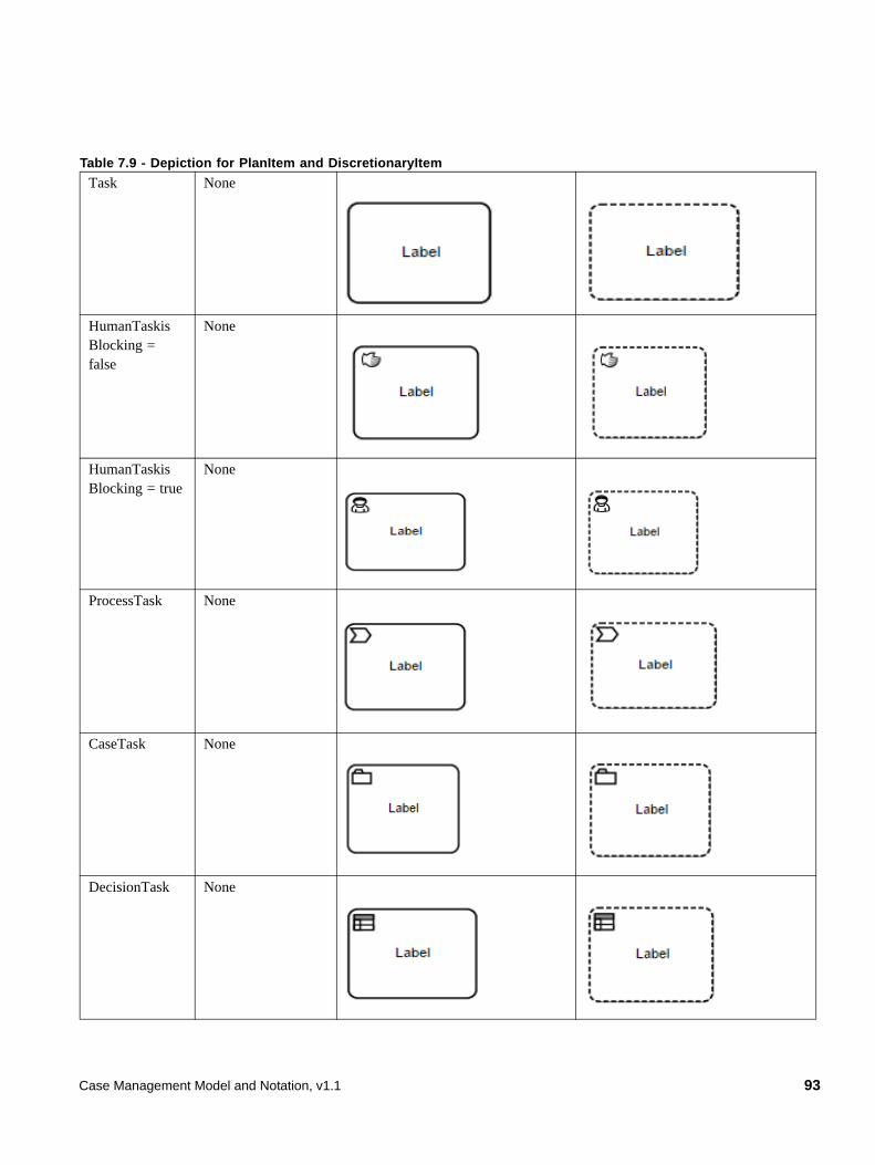
Task None
HumanTaskis Blocking = false
None
HumanTaskis Blocking = true
None
ProcessTask None
CaseTask None
DecisionTask None
Table 7.9 - Depiction for PlanItem and DiscretionaryItem
Case Management Model and Notation, v1.1 93
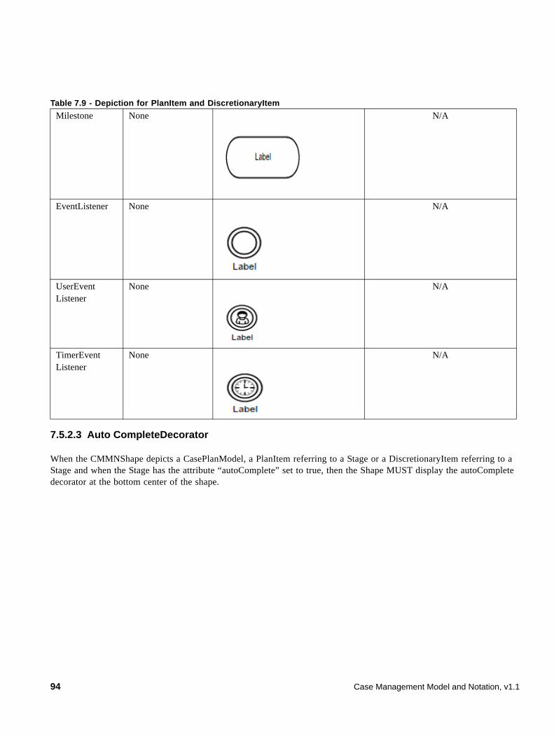
7.5.2.3 Auto CompleteDecorator
When the CMMNShape depicts a CasePlanModel, a PlanItem referring to a Stage or a DiscretionaryItem referring to a Stage and when the Stage has the attribute “autoComplete” set to true, then the Shape MUST display the autoComplete decorator at the bottom center of the shape.
Milestone None N/A
EventListener None N/A
UserEvent Listener
None N/A
TimerEvent Listener
None N/A
Table 7.9 - Depiction for PlanItem and DiscretionaryItem
94 Case Management Model and Notation, v1.1
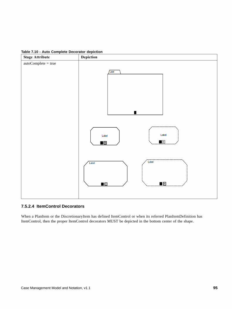
7.5.2.4 ItemControl Decorators
When a PlanItem or the DiscretionaryItem has defined ItemControl or when its referred PlanItemDefinition has ItemControl, then the proper ItemControl decorators MUST be depicted in the bottom center of the shape.
Table 7.10 - Auto Complete Decorator depiction
Stage Attribute Depiction
autoComplete = true
Case Management Model and Notation, v1.1 95
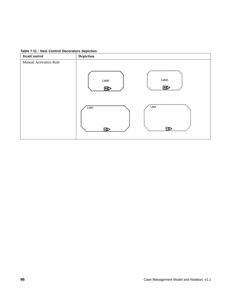
Table 7.11 - Item Control Decorators depiction
ItemControl Depiction
Manual Activation Rule
96 Case Management Model and Notation, v1.1
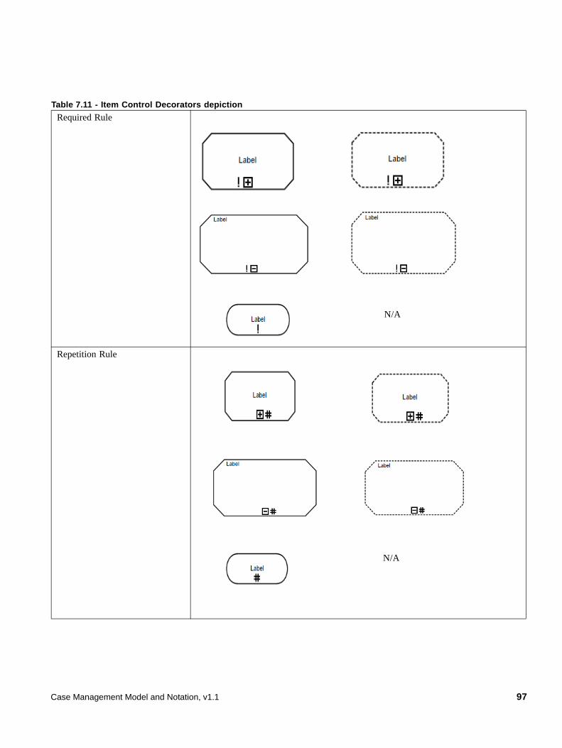
Required Rule
Repetition Rule
Table 7.11 - Item Control Decorators depiction
N/A
N/A
Case Management Model and Notation, v1.1 97
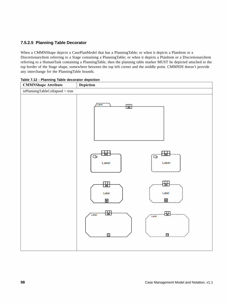
7.5.2.5 Planning Table Decorator
When a CMMNShape depicts a CasePlanModel that has a PlanningTable; or when it depicts a PlanItem or a DiscretionaryItem referring to a Stage containing a PlanningTable; or when it depicts a PlanItem or a DiscretionaryItem referring to a HumanTask containing a PlanningTable, then the planning table marker MUST be depicted attached to the top border of the Stage shape, somewhere between the top left corner and the middle point. CMMNDI doesn’t provide any interchange for the PlanningTable bounds.
Table 7.12 - Planning Table decorator depiction
CMMNShape Attribute Depiction
isPlanningTableCollapsed = true
98 Case Management Model and Notation, v1.1

7.5.2.6 Entry criterion
When a CMMNShape refers to an Entry Criterion, it is depicted attached to the border of the PlanItem or the DiscretionaryItem holding that Entry Criterion.
Only PlanItem and DiscretionaryItem referring to a Task, a Stage or a Milestone can have Entry Criterion.
IsPlanningTableCollapsed = false
When the PlanningTable is expanded. DiscretionaryItem(s) MUST be depicted either using Discretionary Association for Human Task or inside the Stage/CasePlanModel.
Table 7.12 - Planning Table decorator depiction
Case Management Model and Notation, v1.1 99
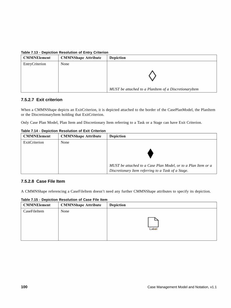
7.5.2.7 Exit criterion
When a CMMNShape depicts an ExitCriterion, it is depicted attached to the border of the CasePlanModel, the PlanItem or the DiscretionaryItem holding that ExitCriterion.
Only Case Plan Model, Plan Item and Discretionary Item referring to a Task or a Stage can have Exit Criterion.
7.5.2.8 Case File Item
A CMMNShape referencing a CaseFileItem doesn’t need any further CMMNShape attributes to specify its depiction.
Table 7.13 - Depiction Resolution of Entry Criterion
CMMNElement CMMNShape Attribute Depiction
EntryCriterion None
MUST be attached to a PlanItem of a DiscretionaryItem
Table 7.14 - Depiction Resolution of Exit Criterion
CMMNElement CMMNShape Attribute Depiction
ExitCriterion None
MUST be attached to a Case Plan Model, or to a Plan Item or a Discretionary Item referring to a Task of a Stage.
Table 7.15 - Depiction Resolution of Case File Item
CMMNElement CMMNShape Attribute Depiction
CaseFileItem None
100 Case Management Model and Notation, v1.1
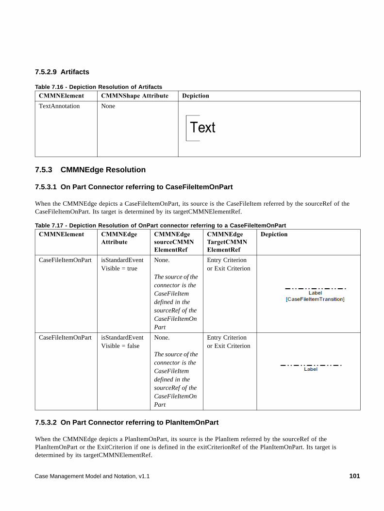
7.5.2.9 Artifacts
7.5.3 CMMNEdge Resolution
7.5.3.1 On Part Connector referring to CaseFileItemOnPart
When the CMMNEdge depicts a CaseFileItemOnPart, its source is the CaseFileItem referred by the sourceRef of the CaseFileItemOnPart. Its target is determined by its targetCMMNElementRef.
7.5.3.2 On Part Connector referring to PlanItemOnPart
When the CMMNEdge depicts a PlanItemOnPart, its source is the PlanItem referred by the sourceRef of the PlanItemOnPart or the ExitCriterion if one is defined in the exitCriterionRef of the PlanItemOnPart. Its target is determined by its targetCMMNElementRef.
Table 7.16 - Depiction Resolution of Artifacts
CMMNElement CMMNShape Attribute Depiction
TextAnnotation None
Table 7.17 - Depiction Resolution of OnPart connector referring to a CaseFileItemOnPart
CMMNElement CMMNEdge Attribute
CMMNEdge sourceCMMN ElementRef
CMMNEdge TargetCMMN ElementRef
Depiction
CaseFileItemOnPart isStandardEventVisible = true
None.
The source of the connector is the CaseFileItem defined in the sourceRef of the CaseFileItemOnPart
Entry Criterion or Exit Criterion
CaseFileItemOnPart isStandardEventVisible = false
None.
The source of the connector is the CaseFileItem defined in the sourceRef of the CaseFileItemOnPart
Entry Criterion or Exit Criterion
Case Management Model and Notation, v1.1 101
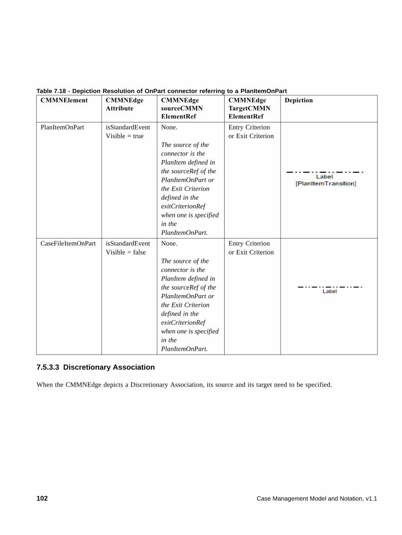
7.5.3.3 Discretionary Association
When the CMMNEdge depicts a Discretionary Association, its source and its target need to be specified.
Table 7.18 - Depiction Resolution of OnPart connector referring to a PlanItemOnPart
CMMNElement CMMNEdge Attribute
CMMNEdge sourceCMMN ElementRef
CMMNEdge TargetCMMN ElementRef
Depiction
PlanItemOnPart isStandardEventVisible = true
None.
The source of the connector is the PlanItem defined in the sourceRef of the PlanItemOnPart or the Exit Criterion defined in the exitCriterionRef when one is specified in the PlanItemOnPart.
Entry Criterion or Exit Criterion
CaseFileItemOnPart isStandardEventVisible = false
None.
The source of the connector is the PlanItem defined in the sourceRef of the PlanItemOnPart or the Exit Criterion defined in the exitCriterionRef when one is specified in the PlanItemOnPart.
Entry Criterion or Exit Criterion
102 Case Management Model and Notation, v1.1
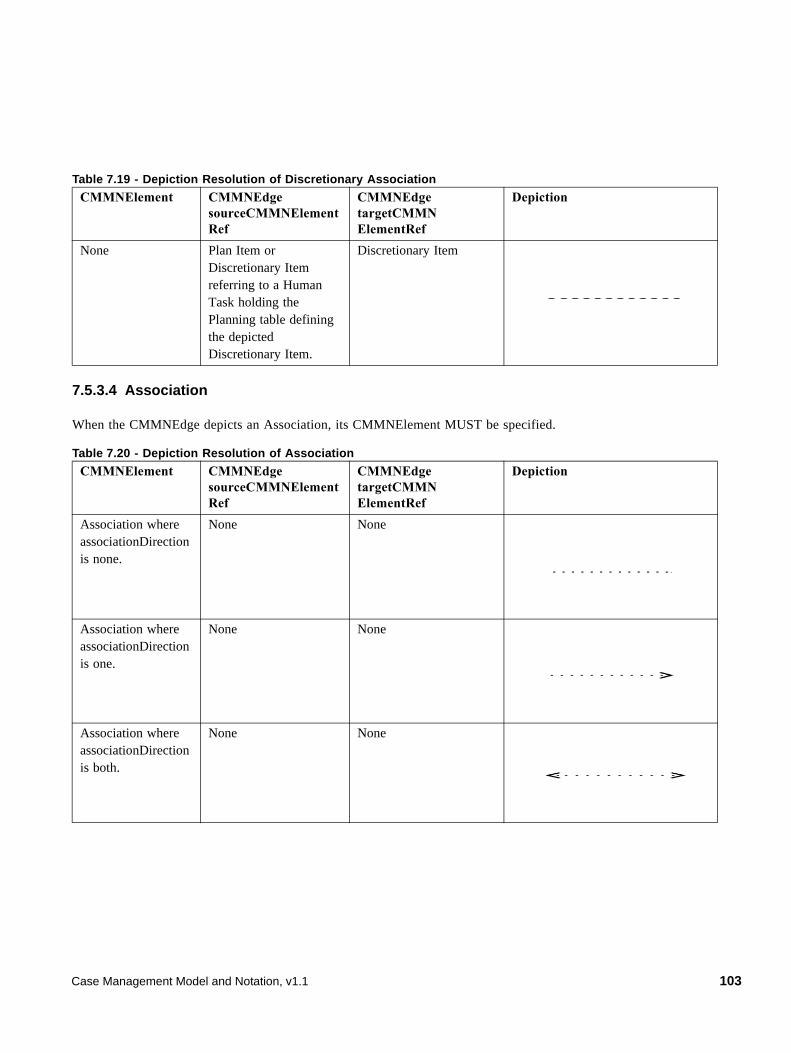
7.5.3.4 Association
When the CMMNEdge depicts an Association, its CMMNElement MUST be specified.
Table 7.19 - Depiction Resolution of Discretionary Association
CMMNElement CMMNEdge sourceCMMNElementRef
CMMNEdge targetCMMN ElementRef
Depiction
None Plan Item or Discretionary Item referring to a Human Task holding the Planning table defining the depicted Discretionary Item.
Discretionary Item
Table 7.20 - Depiction Resolution of Association
CMMNElement CMMNEdge sourceCMMNElementRef
CMMNEdge targetCMMN ElementRef
Depiction
Association where associationDirection is none.
None None
Association where associationDirection is one.
None None
Association where associationDirection is both.
None None
Case Management Model and Notation, v1.1 103

104 Case Management Model and Notation, v1.1
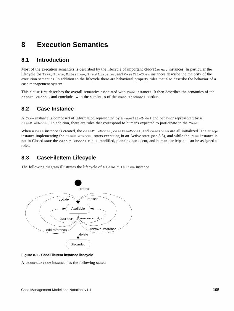
8 Execution Semantics
8.1 Introduction
Most of the execution semantics is described by the lifecycle of important CMMNElement instances. In particular the lifecycle for Task, Stage, Milestone, EventListener, and CaseFileItem instances describe the majority of the execution semantics. In addition to the lifecycle there are behavioral property rules that also describe the behavior of a case management system.
This clause first describes the overall semantics associated with Case instances. It then describes the semantics of the caseFileModel, and concludes with the semantics of the casePlanModel portion.
8.2 Case Instance
A Case instance is composed of information represented by a caseFileModel and behavior represented by a casePlanModel. In addition, there are roles that correspond to humans expected to participate in the Case.
When a Case instance is created, the caseFileModel, casePlanModel, and caseRoles are all initialized. The Stage instance implementing the casePlanModel starts executing in an Active state (see 8.3), and while the Case instance is not in Closed state the caseFileModel can be modified, planning can occur, and human participants can be assigned to roles.
8.3 CaseFileItem Lifecycle
The following diagram illustrates the lifecycle of a CaseFileItem instance
Figure 8.1 - CaseFileItem instance lifecycle
A CaseFileItem instance has the following states:
Case Management Model and Notation, v1.1 105
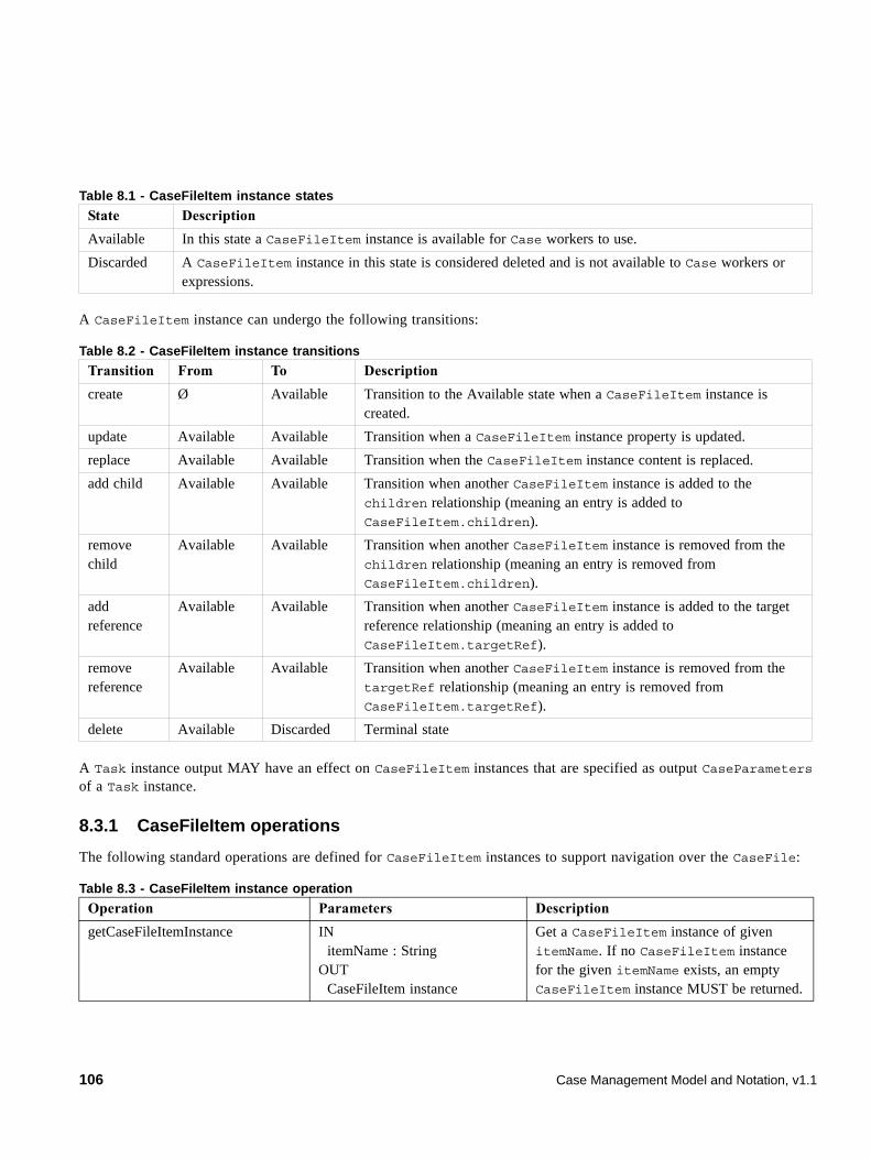
A CaseFileItem instance can undergo the following transitions:
A Task instance output MAY have an effect on CaseFileItem instances that are specified as output CaseParameters of a Task instance.
8.3.1 CaseFileItem operations
The following standard operations are defined for CaseFileItem instances to support navigation over the CaseFile:
Table 8.1 - CaseFileItem instance states
State Description
Available In this state a CaseFileItem instance is available for Case workers to use.
Discarded A CaseFileItem instance in this state is considered deleted and is not available to Case workers or expressions.
Table 8.2 - CaseFileItem instance transitions
Transition From To Description
create Ø Available Transition to the Available state when a CaseFileItem instance is created.
update Available Available Transition when a CaseFileItem instance property is updated.
replace Available Available Transition when the CaseFileItem instance content is replaced.
add child Available Available Transition when another CaseFileItem instance is added to the children relationship (meaning an entry is added to CaseFileItem.children).
remove child
Available Available Transition when another CaseFileItem instance is removed from the children relationship (meaning an entry is removed from CaseFileItem.children).
add reference
Available Available Transition when another CaseFileItem instance is added to the target reference relationship (meaning an entry is added to CaseFileItem.targetRef).
remove reference
Available Available Transition when another CaseFileItem instance is removed from the targetRef relationship (meaning an entry is removed from CaseFileItem.targetRef).
delete Available Discarded Terminal state
Table 8.3 - CaseFileItem instance operation
Operation Parameters Description
getCaseFileItemInstance IN itemName : StringOUT CaseFileItem instance
Get a CaseFileItem instance of given itemName. If no CaseFileItem instance for the given itemName exists, an empty CaseFileItem instance MUST be returned.
106 Case Management Model and Notation, v1.1
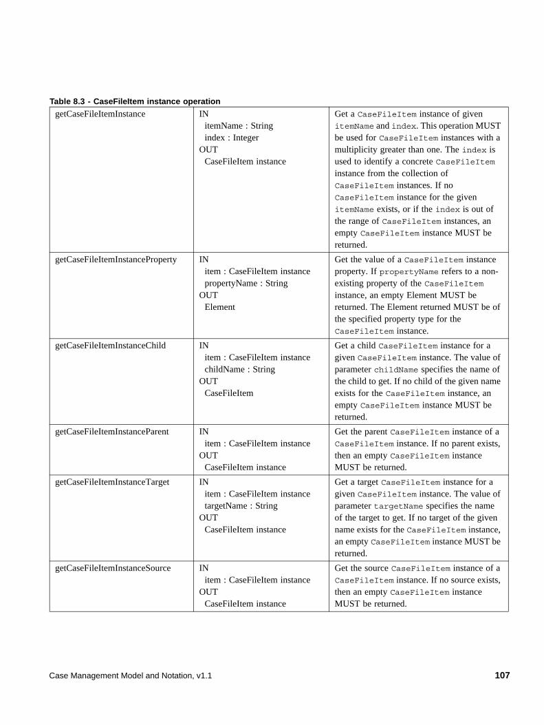
getCaseFileItemInstance IN itemName : String index : IntegerOUT CaseFileItem instance
Get a CaseFileItem instance of given itemName and index. This operation MUST be used for CaseFileItem instances with a multiplicity greater than one. The index is used to identify a concrete CaseFileItem instance from the collection of CaseFileItem instances. If no CaseFileItem instance for the given itemName exists, or if the index is out of the range of CaseFileItem instances, an empty CaseFileItem instance MUST be returned.
getCaseFileItemInstanceProperty IN item : CaseFileItem instance propertyName : StringOUT Element
Get the value of a CaseFileItem instance property. If propertyName refers to a non-existing property of the CaseFileItem instance, an empty Element MUST be returned. The Element returned MUST be of the specified property type for the CaseFileItem instance.
getCaseFileItemInstanceChild IN item : CaseFileItem instance childName : StringOUT CaseFileItem
Get a child CaseFileItem instance for a given CaseFileItem instance. The value of parameter childName specifies the name of the child to get. If no child of the given name exists for the CaseFileItem instance, an empty CaseFileItem instance MUST be returned.
getCaseFileItemInstanceParent IN item : CaseFileItem instanceOUT CaseFileItem instance
Get the parent CaseFileItem instance of a CaseFileItem instance. If no parent exists, then an empty CaseFileItem instance MUST be returned.
getCaseFileItemInstanceTarget IN item : CaseFileItem instance targetName : StringOUT CaseFileItem instance
Get a target CaseFileItem instance for a given CaseFileItem instance. The value of parameter targetName specifies the name of the target to get. If no target of the given name exists for the CaseFileItem instance, an empty CaseFileItem instance MUST be returned.
getCaseFileItemInstanceSource IN item : CaseFileItem instance OUT CaseFileItem instance
Get the source CaseFileItem instance of a CaseFileItem instance. If no source exists, then an empty CaseFileItem instance MUST be returned.
Table 8.3 - CaseFileItem instance operation
Case Management Model and Notation, v1.1 107
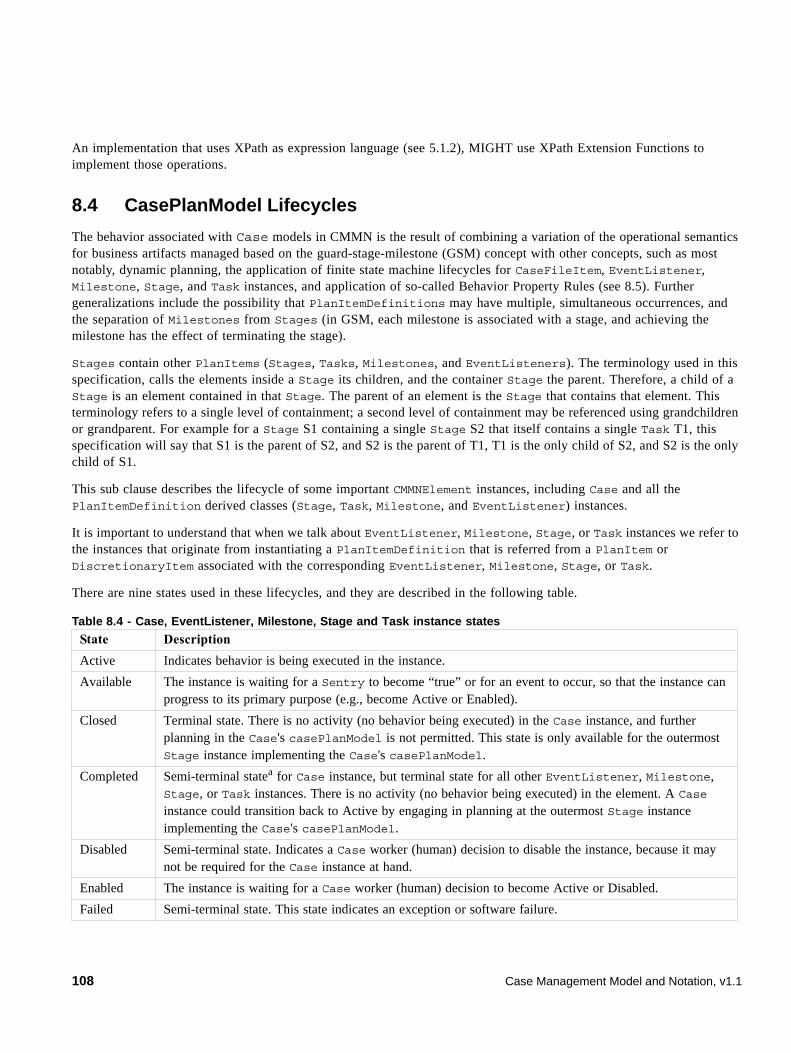
An implementation that uses XPath as expression language (see 5.1.2), MIGHT use XPath Extension Functions to implement those operations.
8.4 CasePlanModel Lifecycles
The behavior associated with Case models in CMMN is the result of combining a variation of the operational semantics for business artifacts managed based on the guard-stage-milestone (GSM) concept with other concepts, such as most notably, dynamic planning, the application of finite state machine lifecycles for CaseFileItem, EventListener, Milestone, Stage, and Task instances, and application of so-called Behavior Property Rules (see 8.5). Further generalizations include the possibility that PlanItemDefinitions may have multiple, simultaneous occurrences, and the separation of Milestones from Stages (in GSM, each milestone is associated with a stage, and achieving the milestone has the effect of terminating the stage).
Stages contain other PlanItems (Stages, Tasks, Milestones, and EventListeners). The terminology used in this specification, calls the elements inside a Stage its children, and the container Stage the parent. Therefore, a child of a Stage is an element contained in that Stage. The parent of an element is the Stage that contains that element. This terminology refers to a single level of containment; a second level of containment may be referenced using grandchildren or grandparent. For example for a Stage S1 containing a single Stage S2 that itself contains a single Task T1, this specification will say that S1 is the parent of S2, and S2 is the parent of T1, T1 is the only child of S2, and S2 is the only child of S1.
This sub clause describes the lifecycle of some important CMMNElement instances, including Case and all the PlanItemDefinition derived classes (Stage, Task, Milestone, and EventListener) instances.
It is important to understand that when we talk about EventListener, Milestone, Stage, or Task instances we refer to the instances that originate from instantiating a PlanItemDefinition that is referred from a PlanItem or DiscretionaryItem associated with the corresponding EventListener, Milestone, Stage, or Task.
There are nine states used in these lifecycles, and they are described in the following table.
Table 8.4 - Case, EventListener, Milestone, Stage and Task instance states
State Description
Active Indicates behavior is being executed in the instance.
Available The instance is waiting for a Sentry to become “true” or for an event to occur, so that the instance can progress to its primary purpose (e.g., become Active or Enabled).
Closed Terminal state. There is no activity (no behavior being executed) in the Case instance, and further planning in the Case's casePlanModel is not permitted. This state is only available for the outermost Stage instance implementing the Case's casePlanModel.
Completed Semi-terminal statea for Case instance, but terminal state for all other EventListener, Milestone, Stage, or Task instances. There is no activity (no behavior being executed) in the element. A Case instance could transition back to Active by engaging in planning at the outermost Stage instance implementing the Case's casePlanModel.
Disabled Semi-terminal state. Indicates a Case worker (human) decision to disable the instance, because it may not be required for the Case instance at hand.
Enabled The instance is waiting for a Case worker (human) decision to become Active or Disabled.
Failed Semi-terminal state. This state indicates an exception or software failure.
108 Case Management Model and Notation, v1.1
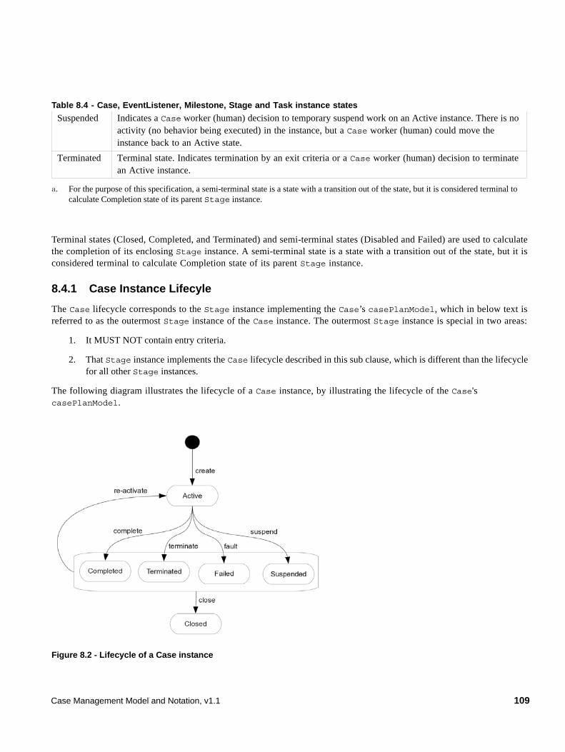
Terminal states (Closed, Completed, and Terminated) and semi-terminal states (Disabled and Failed) are used to calculate the completion of its enclosing Stage instance. A semi-terminal state is a state with a transition out of the state, but it is considered terminal to calculate Completion state of its parent Stage instance.
8.4.1 Case Instance Lifecyle
The Case lifecycle corresponds to the Stage instance implementing the Case’s casePlanModel, which in below text is referred to as the outermost Stage instance of the Case instance. The outermost Stage instance is special in two areas:
1. It MUST NOT contain entry criteria.
2. That Stage instance implements the Case lifecycle described in this sub clause, which is different than the lifecycle for all other Stage instances.
The following diagram illustrates the lifecycle of a Case instance, by illustrating the lifecycle of the Case's casePlanModel.
Figure 8.2 - Lifecycle of a Case instance
Suspended Indicates a Case worker (human) decision to temporary suspend work on an Active instance. There is no activity (no behavior being executed) in the instance, but a Case worker (human) could move the instance back to an Active state.
Terminated Terminal state. Indicates termination by an exit criteria or a Case worker (human) decision to terminate an Active instance.
a. For the purpose of this specification, a semi-terminal state is a state with a transition out of the state, but it is considered terminal to calculate Completion state of its parent Stage instance.
Table 8.4 - Case, EventListener, Milestone, Stage and Task instance states
Case Management Model and Notation, v1.1 109
A Case instance has the following states:
A Case instance can undergo the following transitions:
Table 8.5 - Case instance states
State Description
Active In this state the Case instance is executing; meaning the outermost Stage instance is in the Active state.
Suspended This state allows a Case worker (human) to temporarily suspend an executing Case instance. A Case instance MUST propagate this state to its outermost Stage instance. This state MUST then be propagated down to the outermost Stage instance’s contained EventListener, Milestone, Stage, and Task instances.
Completed The Case instance is completed, when all the required Milestone, Stage, and Task instances in the outermost Stage instance are completed (completed or terminated), and there are no executing (Active) Stage or Task instances.
Terminated Terminal state. This state can be achieved by an exit criteria and also allows a Case worker (human) to terminate an executing Case instance. This state is reached when the outermost Stage instance reaches it.
Failed Semi-terminal state. This state is reached when the outermost Stage instance reaches it. The state indicates an exception or software failure.
Closed Terminal state. In this state no new activity is allowed in the Case. The Case instance caseFileModel and all its content becomes read only, and no new Task or Stage instances can be planned.
Table 8.6 - Case instance transitions
Transition From To Description
create Ø Active Transition to the initial state (Active) when the Case instance is created. The outermost Stage instance skips the Available state and MUST transition directly to the Active state, because that Stage instance does not have a (entry criteria) Sentry.
suspend Active Suspended Transition by Case worker (human) decision. This state propagates down to the outermost Stage instance, which in turn propagates it down to all its internal EventListener, Milestone, Stage, and Task instances.
terminate Active Terminated Transition by Case worker (human) decision. This state propagates down to the outermost Stage instance, which in turn propagates it down to all its internal EventListener, Milestone, Stage, and Task instances.
complete Active Completed Transition when all the required Milestone, Stage, and Task instances have reached a terminal state (Closed and Terminated) or a semi-terminal state (Completed, Disabled, and Failed), and there are no executing (Active) Stage or Task instances.
fault Active Failed Transition when the outermost Stage instance reaches the Failed state due to an exception or software failure.
110 Case Management Model and Notation, v1.1
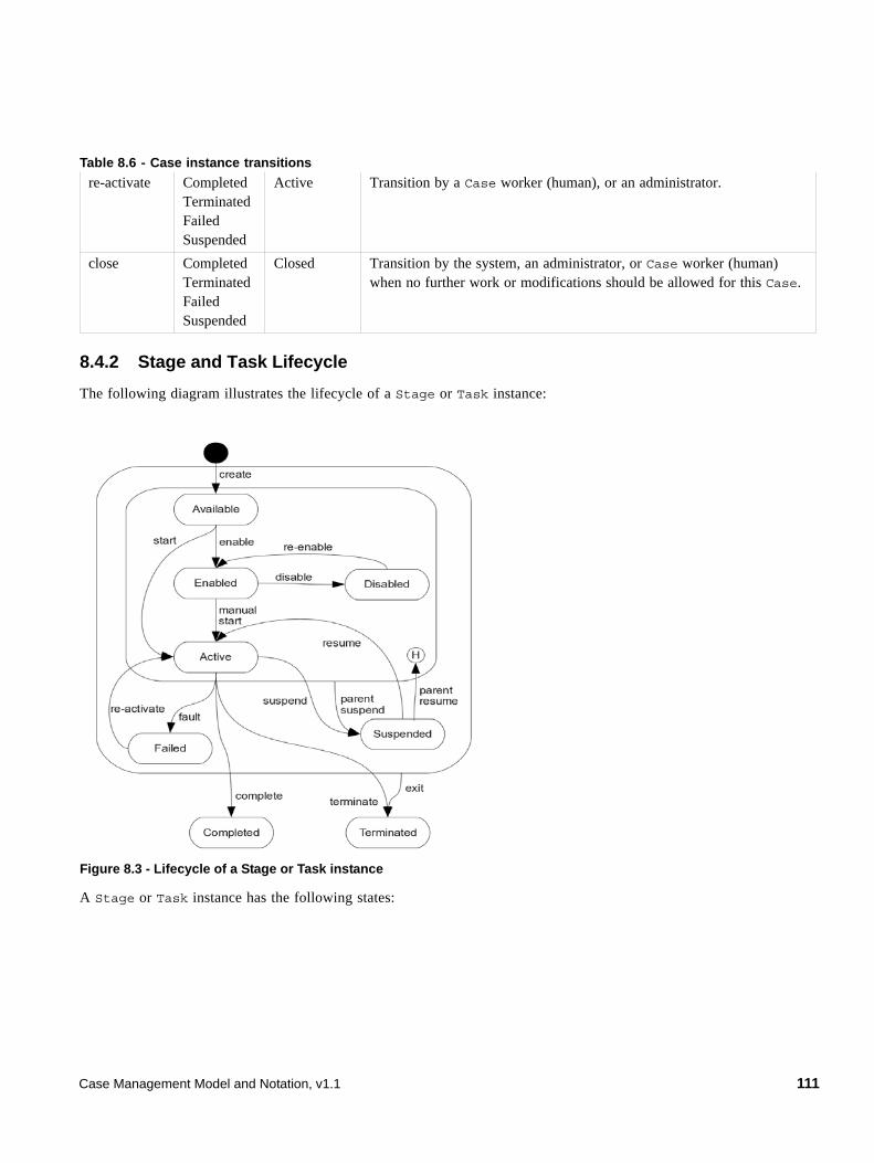
8.4.2 Stage and Task Lifecycle
The following diagram illustrates the lifecycle of a Stage or Task instance:
Figure 8.3 - Lifecycle of a Stage or Task instance
A Stage or Task instance has the following states:
re-activate CompletedTerminatedFailedSuspended
Active Transition by a Case worker (human), or an administrator.
close CompletedTerminatedFailedSuspended
Closed Transition by the system, an administrator, or Case worker (human) when no further work or modifications should be allowed for this Case.
Table 8.6 - Case instance transitions
Case Management Model and Notation, v1.1 111
A Stage or Task instance can undergo the following transitions:
Table 8.7 - Stage and Task instances states
State Description
Available A Stage or Task instance becomes available when
• The Stage instance in which it resides moves into Active state. or
• The Stage or Task has a Sentry with an OnPart that has a sourceRef outside of the enclosing Stage of that Stage or Task and this Sentry is satisfied. In that case, the Stage instance and recursively all Stage instances up to the enclosing Stage of the Stage or Task in which the Stage or Task resides moves into Active state if not already active.
While available, the Stage or Task instance is waiting for its entry criteria (Sentry) to become “true.” A missing entry criteria (Sentry) is considered “true.”
Enabled A Stage or Task instance in this state is waiting for a human to start or disable it. Only Stage or Task instances that require Case worker (human) intervention to start get into this state (ManualActivationRule evaluates to “true”).
Disabled Semi-terminal state. This state is reached when a Case worker (human) decides the Stage or Task instance should not execute in this instance of the Case.
Active The Stage or Task considered instance is executing in this state. Stage instances in this state contain at least one Stage or Task instance in the Available, Enabled, Active, Suspended state, or autoComplete is set to “false.”
Suspended This state allows a Case worker (human) to temporarily suspend an executing Stage or Task instance. A Stage instance MUST propagate this state to all its contained EventListener, Milestone, Stage, and Task instances.
Failed Semi-terminal state. This state indicates an exception or software failure.
Completed Terminal state. This state indicates normal termination of the Stage or Task instance. For a Stage instance it indicates all its contained Stage or Task instances MUST be either completed or terminated.
Terminated Terminal state. This state indicates a termination by a Case worker (human), or termination by reaching the exit criteria sentry. A Stage instance MUST propagate this state to all its contained EventListener, Milestone, Stage, and Task instances.
Table 8.8 - Stage and Task instance transitions
Transition From To Description
create Ø Available Transition to the initial state (Available) when the Stage or Task instance is created. This happens when the Stage instance containing this Stage or Task instance transitions to Active. The RepetitionRule Boolean expression MUST be evaluated in this transition. The RequiredRule Boolean expression MUST be evaluated in this transition, and its Boolean value SHOULD be maintained for the rest of the life of the Stage or Task instance.
112 Case Management Model and Notation, v1.1
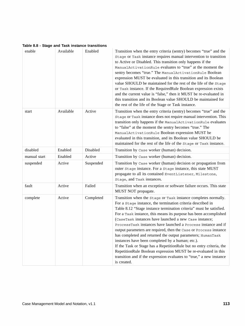
enable Available Enabled Transition when the entry criteria (sentry) becomes “true” and the Stage or Task instance requires manual intervention to transition to Active or Disabled. This transition only happens if the ManualActivationRule evaluates to “true” at the moment the sentry becomes “true.” The ManualActivationRule Boolean expression MUST be evaluated in this transition and its Boolean value SHOULD be maintained for the rest of the life of the Stage or Task instance. If the RequiredRule Boolean expression exists and the current value is “false,” then it MUST be re-evaluated in this transition and its Boolean value SHOULD be maintained for the rest of the life of the Stage or Task instance.
start Available Active Transition when the entry criteria (sentry) becomes “true” and the Stage or Task instance does not require manual intervention. This transition only happens if the ManualActivationRule evaluates to “false” at the moment the sentry becomes “true.” The ManualActivationRule Boolean expression MUST be evaluated in this transition, and its Boolean value SHOULD be maintained for the rest of the life of the Stage or Task instance.
disabled Enabled Disabled Transition by Case worker (human) decision.
manual start Enabled Active Transition by Case worker (human) decision.
suspended Active Suspended Transition by Case worker (human) decision or propagation from outer Stage instance. For a Stage instance, this state MUST propagate to all its contained EventListener, Milestone, Stage, and Task instances.
fault Active Failed Transition when an exception or software failure occurs. This state MUST NOT propagate.
complete Active Completed Transition when the Stage or Task instance completes normally. For a Stage instance, the termination criteria described in Table 8.12 “Stage instance termination criteria” must be satisfied. For a Task instance, this means its purpose has been accomplished (CaseTask instances have launched a new Case instance; ProcessTask instances have launched a Process instance and if output parameters are required, then the Case or Process instance has completed and returned the output parameters; HumanTask instances have been completed by a human; etc.).If the Task or Stage has a RepetitionRule but no entry criteria, the RepetitionRule Boolean expression MUST be re-evaluated in this transition and if the expression evaluates to “true,” a new instance is created.
Table 8.8 - Stage and Task instance transitions
Case Management Model and Notation, v1.1 113
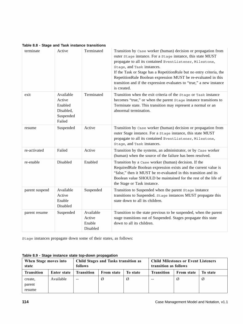
Stage instances propagate down some of their states, as follows:
terminate Active Terminated Transition by Case worker (human) decision or propagation from outer Stage instance. For a Stage instance, this state MUST propagate to all its contained EventListener, Milestone, Stage, and Task instances.If the Task or Stage has a RepetitionRule but no entry criteria, the RepetitionRule Boolean expression MUST be re-evaluated in this transition and if the expression evaluates to “true,” a new instance is created.
exit AvailableActiveEnabledDisabled,SuspendedFailed
Terminated Transition when the exit criteria of the Stage or Task instance becomes “true,” or when the parent Stage instance transitions to Terminate state. This transition may represent a normal or an abnormal termination.
resume Suspended Active Transition by Case worker (human) decision or propagation from outer Stage instance. For a Stage instance, this state MUST propagate to all its contained EventListener, Milestone, Stage, and Task instances.
re-activated Failed Active Transition by the systems, an administrator, or by Case worker (human) when the source of the failure has been resolved.
re-enable Disabled Enabled Transition by a Case worker (human) decision. If the RequiredRule Boolean expression exists and the current value is “false,” then it MUST be re-evaluated in this transition and its Boolean value SHOULD be maintained for the rest of the life of the Stage or Task instance.
parent suspend AvailableActiveEnableDisabled
Suspended Transition to Suspended when the parent Stage instance transitions to Suspended. Stage instances MUST propagate this state down to all its children.
parent resume Suspended AvailableActiveEnableDisabled
Transition to the state previous to be suspended, when the parent stage transitions out of Suspended. Stages propagate this state down to all its children.
Table 8.9 - Stage instance state top-down propagation
When Stage moves into state
Child Stages and Tasks transition as follows
Child Milestones or Event Listeners transition as follows
Transition Enter state Transition From state To state Transition From state To state
create, parent resume
Available -- Ø Ø -- Ø Ø
Table 8.8 - Stage and Task instance transitions
114 Case Management Model and Notation, v1.1
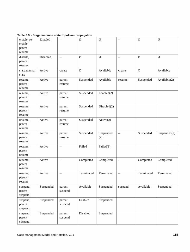
enable, re-enable, parent resume
Enabled -- Ø Ø -- Ø Ø
disable, parent resume
Disabled -- Ø Ø -- Ø Ø
start, manual start
Active create Ø Available create Ø Available
resume, parent resume
Active parent resume
Suspended Available resume Suspended Available(2)
resume, parent resume
Active parent resume
Suspended Enabled(2)
resume, parent resume
Active parent resume
Suspended Disabled(2)
resume, parent resume
Active parent resume
Suspended Active(2)
resume, parent resume
Active parent resume
Suspended Suspended (2)
-- Suspended Suspended(2)
resume, parent resume
Active -- Failed Failed(1)
resume, parent resume
Active -- Completed Completed -- Completed Completed
resume, parent resume
Active -- Terminated Terminated -- Terminated Terminated
suspend, parent suspend
Suspended parent suspend
Available Suspended suspend Available Suspended
suspend, parent suspend
Suspended parent suspend
Enabled Suspended
suspend, parent suspend
Suspended parent suspend
Disabled Suspended
Table 8.9 - Stage instance state top-down propagation
Case Management Model and Notation, v1.1 115
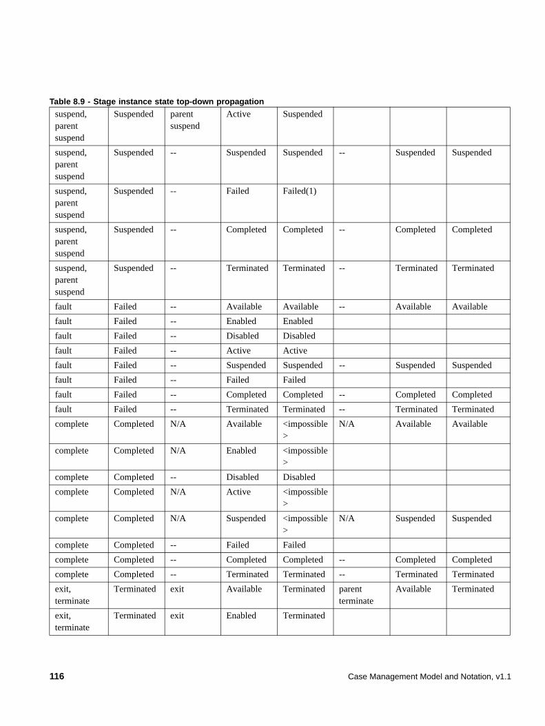
suspend, parent suspend
Suspended parent suspend
Active Suspended
suspend, parent suspend
Suspended -- Suspended Suspended -- Suspended Suspended
suspend, parent suspend
Suspended -- Failed Failed(1)
suspend, parent suspend
Suspended -- Completed Completed -- Completed Completed
suspend, parent suspend
Suspended -- Terminated Terminated -- Terminated Terminated
fault Failed -- Available Available -- Available Available
fault Failed -- Enabled Enabled
fault Failed -- Disabled Disabled
fault Failed -- Active Active
fault Failed -- Suspended Suspended -- Suspended Suspended
fault Failed -- Failed Failed
fault Failed -- Completed Completed -- Completed Completed
fault Failed -- Terminated Terminated -- Terminated Terminated
complete Completed N/A Available <impossible>
N/A Available Available
complete Completed N/A Enabled <impossible>
complete Completed -- Disabled Disabled
complete Completed N/A Active <impossible>
complete Completed N/A Suspended <impossible>
N/A Suspended Suspended
complete Completed -- Failed Failed
complete Completed -- Completed Completed -- Completed Completed
complete Completed -- Terminated Terminated -- Terminated Terminated
exit, terminate
Terminated exit Available Terminated parent terminate
Available Terminated
exit, terminate
Terminated exit Enabled Terminated
Table 8.9 - Stage instance state top-down propagation
116 Case Management Model and Notation, v1.1
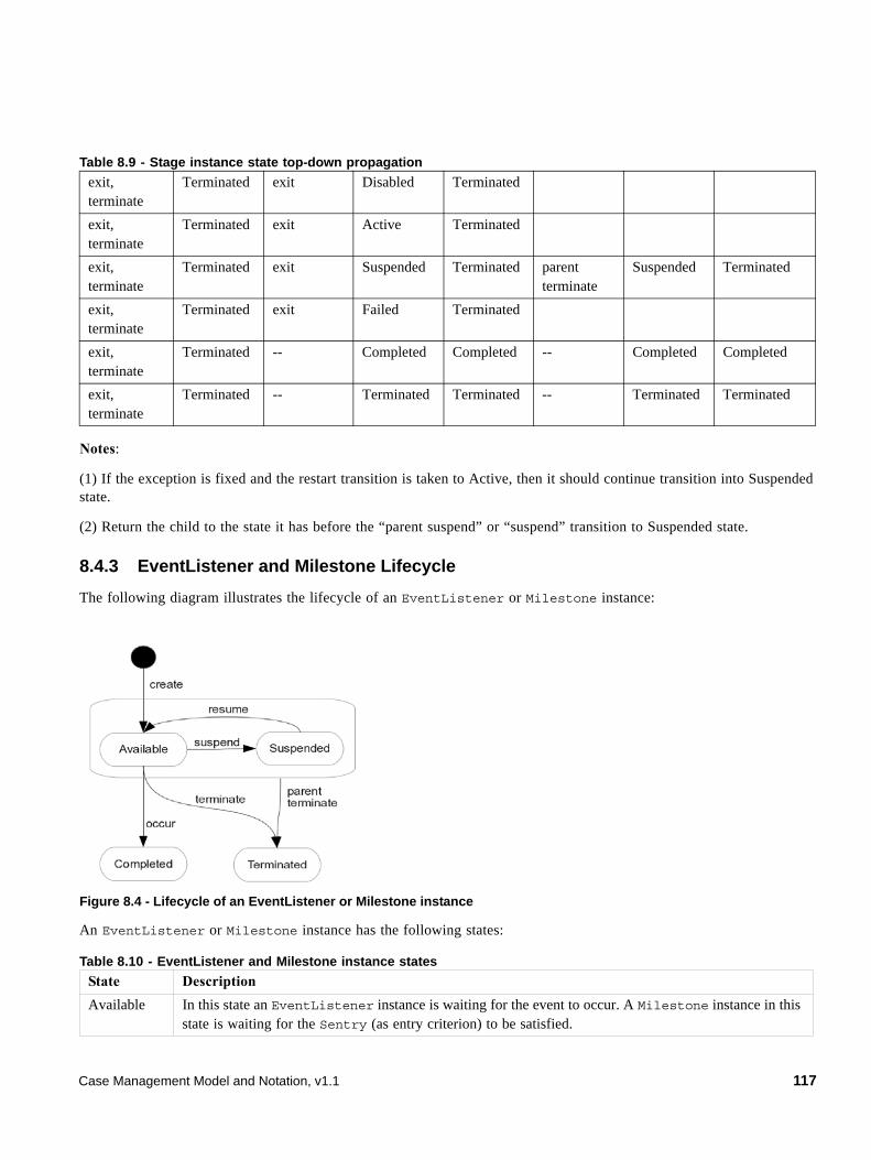
Notes:
(1) If the exception is fixed and the restart transition is taken to Active, then it should continue transition into Suspended state.
(2) Return the child to the state it has before the “parent suspend” or “suspend” transition to Suspended state.
8.4.3 EventListener and Milestone Lifecycle
The following diagram illustrates the lifecycle of an EventListener or Milestone instance:
Figure 8.4 - Lifecycle of an EventListener or Milestone instance
An EventListener or Milestone instance has the following states:
exit, terminate
Terminated exit Disabled Terminated
exit, terminate
Terminated exit Active Terminated
exit, terminate
Terminated exit Suspended Terminated parent terminate
Suspended Terminated
exit, terminate
Terminated exit Failed Terminated
exit, terminate
Terminated -- Completed Completed -- Completed Completed
exit, terminate
Terminated -- Terminated Terminated -- Terminated Terminated
Table 8.10 - EventListener and Milestone instance states
State Description
Available In this state an EventListener instance is waiting for the event to occur. A Milestone instance in this state is waiting for the Sentry (as entry criterion) to be satisfied.
Table 8.9 - Stage instance state top-down propagation
Case Management Model and Notation, v1.1 117
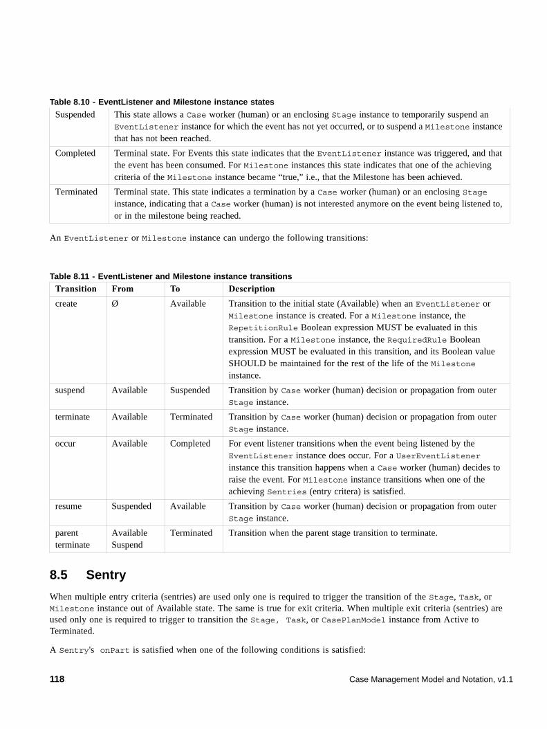
An EventListener or Milestone instance can undergo the following transitions:
8.5 Sentry
When multiple entry criteria (sentries) are used only one is required to trigger the transition of the Stage, Task, or Milestone instance out of Available state. The same is true for exit criteria. When multiple exit criteria (sentries) are used only one is required to trigger to transition the Stage, Task, or CasePlanModel instance from Active to Terminated.
A Sentry's onPart is satisfied when one of the following conditions is satisfied:
Suspended This state allows a Case worker (human) or an enclosing Stage instance to temporarily suspend an EventListener instance for which the event has not yet occurred, or to suspend a Milestone instance that has not been reached.
Completed Terminal state. For Events this state indicates that the EventListener instance was triggered, and that the event has been consumed. For Milestone instances this state indicates that one of the achieving criteria of the Milestone instance became “true,” i.e., that the Milestone has been achieved.
Terminated Terminal state. This state indicates a termination by a Case worker (human) or an enclosing Stage instance, indicating that a Case worker (human) is not interested anymore on the event being listened to, or in the milestone being reached.
Table 8.11 - EventListener and Milestone instance transitions
Transition From To Description
create Ø Available Transition to the initial state (Available) when an EventListener or Milestone instance is created. For a Milestone instance, the RepetitionRule Boolean expression MUST be evaluated in this transition. For a Milestone instance, the RequiredRule Boolean expression MUST be evaluated in this transition, and its Boolean value SHOULD be maintained for the rest of the life of the Milestone instance.
suspend Available Suspended Transition by Case worker (human) decision or propagation from outer Stage instance.
terminate Available Terminated Transition by Case worker (human) decision or propagation from outer Stage instance.
occur Available Completed For event listener transitions when the event being listened by the EventListener instance does occur. For a UserEventListener instance this transition happens when a Case worker (human) decides to raise the event. For Milestone instance transitions when one of the achieving Sentries (entry critera) is satisfied.
resume Suspended Available Transition by Case worker (human) decision or propagation from outer Stage instance.
parent terminate
AvailableSuspend
Terminated Transition when the parent stage transition to terminate.
Table 8.10 - EventListener and Milestone instance states
118 Case Management Model and Notation, v1.1
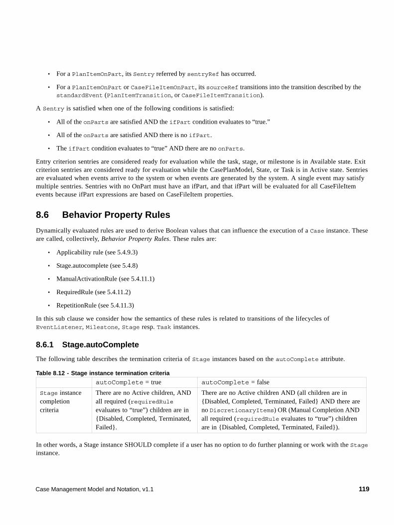
• For a PlanItemOnPart, its Sentry referred by sentryRef has occurred.
• For a PlanItemOnPart or CaseFileItemOnPart, its sourceRef transitions into the transition described by the standardEvent (PlanItemTransition, or CaseFileItemTransition).
A Sentry is satisfied when one of the following conditions is satisfied:
• All of the onParts are satisfied AND the ifPart condition evaluates to “true.”
• All of the onParts are satisfied AND there is no ifPart.
• The ifPart condition evaluates to “true” AND there are no onParts.
Entry criterion sentries are considered ready for evaluation while the task, stage, or milestone is in Available state. Exit criterion sentries are considered ready for evaluation while the CasePlanModel, State, or Task is in Active state. Sentries are evaluated when events arrive to the system or when events are generated by the system. A single event may satisfy multiple sentries. Sentries with no OnPart must have an ifPart, and that ifPart will be evaluated for all CaseFileItem events because ifPart expressions are based on CaseFileItem properties.
8.6 Behavior Property Rules
Dynamically evaluated rules are used to derive Boolean values that can influence the execution of a Case instance. These are called, collectively, Behavior Property Rules. These rules are:
• Applicability rule (see 5.4.9.3)
• Stage.autocomplete (see 5.4.8)
• ManualActivationRule (see 5.4.11.1)
• RequiredRule (see 5.4.11.2)
• RepetitionRule (see 5.4.11.3)
In this sub clause we consider how the semantics of these rules is related to transitions of the lifecycles of EventListener, Milestone, Stage resp. Task instances.
8.6.1 Stage.autoComplete
The following table describes the termination criteria of Stage instances based on the autoComplete attribute.
In other words, a Stage instance SHOULD complete if a user has no option to do further planning or work with the Stage instance.
Table 8.12 - Stage instance termination criteria
autoComplete = true autoComplete = false
Stage instance completion criteria
There are no Active children, AND all required (requiredRule evaluates to “true”) children are in {Disabled, Completed, Terminated, Failed}.
There are no Active children AND (all children are in {Disabled, Completed, Terminated, Failed} AND there are no DiscretionaryItems) OR (Manual Completion AND all required (requiredRule evaluates to “true”) children are in {Disabled, Completed, Terminated, Failed}).
Case Management Model and Notation, v1.1 119
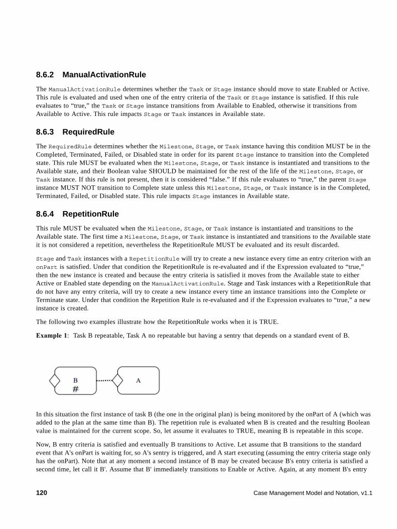
8.6.2 ManualActivationRule
The ManualActivationRule determines whether the Task or Stage instance should move to state Enabled or Active. This rule is evaluated and used when one of the entry criteria of the Task or Stage instance is satisfied. If this rule evaluates to “true,” the Task or Stage instance transitions from Available to Enabled, otherwise it transitions from Available to Active. This rule impacts Stage or Task instances in Available state.
8.6.3 RequiredRule
The RequiredRule determines whether the Milestone, Stage, or Task instance having this condition MUST be in the Completed, Terminated, Failed, or Disabled state in order for its parent Stage instance to transition into the Completed state. This rule MUST be evaluated when the Milestone, Stage, or Task instance is instantiated and transitions to the Available state, and their Boolean value SHOULD be maintained for the rest of the life of the Milestone, Stage, or Task instance. If this rule is not present, then it is considered “false.” If this rule evaluates to “true,” the parent Stage instance MUST NOT transition to Complete state unless this Milestone, Stage, or Task instance is in the Completed, Terminated, Failed, or Disabled state. This rule impacts Stage instances in Available state.
8.6.4 RepetitionRule
This rule MUST be evaluated when the Milestone, Stage, or Task instance is instantiated and transitions to the Available state. The first time a Milestone, Stage, or Task instance is instantiated and transitions to the Available state it is not considered a repetition, nevertheless the RepetitionRule MUST be evaluated and its result discarded.
Stage and Task instances with a RepetitionRule will try to create a new instance every time an entry criterion with an onPart is satisfied. Under that condition the RepetitionRule is re-evaluated and if the Expression evaluated to “true,” then the new instance is created and because the entry criteria is satisfied it moves from the Available state to either Active or Enabled state depending on the ManualActivationRule. Stage and Task instances with a RepetitionRule that do not have any entry criteria, will try to create a new instance every time an instance transitions into the Complete or Terminate state. Under that condition the Repetition Rule is re-evaluated and if the Expression evaluates to “true,” a new instance is created.
The following two examples illustrate how the RepetitionRule works when it is TRUE.
Example 1: Task B repeatable, Task A no repeatable but having a sentry that depends on a standard event of B.
In this situation the first instance of task B (the one in the original plan) is being monitored by the onPart of A (which was added to the plan at the same time than B). The repetition rule is evaluated when B is created and the resulting Boolean value is maintained for the current scope. So, let assume it evaluates to TRUE, meaning B is repeatable in this scope.
Now, B entry criteria is satisfied and eventually B transitions to Active. Let assume that B transitions to the standard event that A's onPart is waiting for, so A's sentry is triggered, and A start executing (assuming the entry criteria stage only has the onPart). Note that at any moment a second instance of B may be created because B's entry criteria is satisfied a second time, let call it B'. Assume that B' immediately transitions to Enable or Active. Again, at any moment B's entry
120 Case Management Model and Notation, v1.1
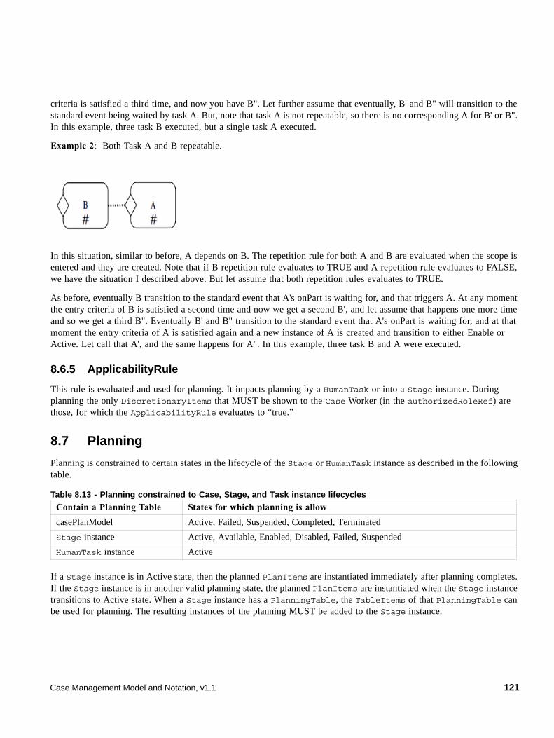
criteria is satisfied a third time, and now you have B". Let further assume that eventually, B' and B" will transition to the standard event being waited by task A. But, note that task A is not repeatable, so there is no corresponding A for B' or B". In this example, three task B executed, but a single task A executed.
Example 2: Both Task A and B repeatable.
In this situation, similar to before, A depends on B. The repetition rule for both A and B are evaluated when the scope is entered and they are created. Note that if B repetition rule evaluates to TRUE and A repetition rule evaluates to FALSE, we have the situation I described above. But let assume that both repetition rules evaluates to TRUE.
As before, eventually B transition to the standard event that A's onPart is waiting for, and that triggers A. At any moment the entry criteria of B is satisfied a second time and now we get a second B', and let assume that happens one more time and so we get a third B". Eventually B' and B" transition to the standard event that A's onPart is waiting for, and at that moment the entry criteria of A is satisfied again and a new instance of A is created and transition to either Enable or Active. Let call that A', and the same happens for A". In this example, three task B and A were executed.
8.6.5 ApplicabilityRule
This rule is evaluated and used for planning. It impacts planning by a HumanTask or into a Stage instance. During planning the only DiscretionaryItems that MUST be shown to the Case Worker (in the authorizedRoleRef) are those, for which the ApplicabilityRule evaluates to “true.”
8.7 Planning
Planning is constrained to certain states in the lifecycle of the Stage or HumanTask instance as described in the following table.
If a Stage instance is in Active state, then the planned PlanItems are instantiated immediately after planning completes. If the Stage instance is in another valid planning state, the planned PlanItems are instantiated when the Stage instance transitions to Active state. When a Stage instance has a PlanningTable, the TableItems of that PlanningTable can be used for planning. The resulting instances of the planning MUST be added to the Stage instance.
Table 8.13 - Planning constrained to Case, Stage, and Task instance lifecycles
Contain a Planning Table States for which planning is allow
casePlanModel Active, Failed, Suspended, Completed, Terminated
Stage instance Active, Available, Enabled, Disabled, Failed, Suspended
HumanTask instance Active
Case Management Model and Notation, v1.1 121
Case workers planning at a particular HumanTask instance are constrained to use the PlanningTable for that HumanTask instance. The resulting instances of the planning MUST be added to the parent Stage instance of the HumanTask instance. Those planned PlanFragments, Stages, or Tasks are instantiated immediately after planning completes (because the parent Stage instance in which the planning task is taking place is in Active state).
8.8 Connector
Connectors are optional visual elements only and do not have associated execution semantics.
122 Case Management Model and Notation, v1.1
9 Exchange Formats
9.1 Interchanging Incomplete Models
It is common for Case models to be interchanged before they are complete. This occurs frequently when doing iterative modeling, where one user (such as a subject matter expert or business user) first defines a high-level model and then passes it on to another person to complete or refine the model.
Such “incomplete” models are ones in which not all of the mandatory model attributes have been filled in yet or the cardinality lower bound of attributes and associations has not been satisfied.
XMI allows for the interchange of such incomplete models. In CMMN, we extend this capability to interchange of XML files based on the CMMN XML-Schema. In such XML files, implementers are expected to support this interchange by:
• Disregarding missing attributes that are marked as “required” in the CMMN XML-Schema.
• Reducing the lower bound of elements with “minOccurs” greater than 0.
9.2 Machine Readable Files
CMMN machine-readable files (listed on the cover page of this specification) including XSD and XMI files can be found at the OMG site.
9.3 XSD
9.3.1 Document Structure
A domain-specific set of Case model elements is interchanged in one or more CMMN files. The root element of each file MUST be <cmmn:definitions>. The set of files MUST be self-contained, i.e., all definitions that are used in a file MUST be imported directly or indirectly using the <cmmn:import> element.
Each file MUST declare a “targetNamespace” that MAY differ between multiple files of one Case model. CMMN files MAY import non-CMMN files (such as XSD’s and BPMN files) if the contained elements use external definitions.
9.3.2 References within CMMN XSD
All CMMN elements contain IDs and within the CMMN XML-Schema, references to elements are expressed via these IDs. The XML-Schema IDREF (for a reference with multiplicity 1) and IDREFS (for references with multiplicity greater than 1) types are the traditional mechanisms used for referencing by IDs within a single XML file. The CMMN XSD supports referencing by ID, across files, by utilizing QNames. A QName consists of two parts: An (optional) namespace prefix and a local part. When used to reference a CMMN element the local part is expected to be the ID of the element.
For example, consider the following Case:
<case name=”Fraud Investigation” id=”Fraud_Investigation_Case_ID1”> … </case>
When this Case is referenced from another file, the reference would take the following form:
Case Management Model and Notation, v1.1 123

caseRef=”case_ns:Fraud_Investigation_Case_ID1”
where “case_ns” is the namespace prefix associated with the case namespace upon import, and “Fraud_Investigation_Case_ID1” is the value of the ID attribute for the Case.
The CMMN XML-Schema utilizes IDREF and IDREFS wherever possible and resorts to QName only when references can span multiple files. In both situations however, the reference is still based on IDs.
124 Case Management Model and Notation, v1.1