Embed Size (px)
Citation preview
Case IH Viper Pro™ Quick Reference Guide
P/N016-0171-155 Rev. D 06/15 E17142
Copyright 2011
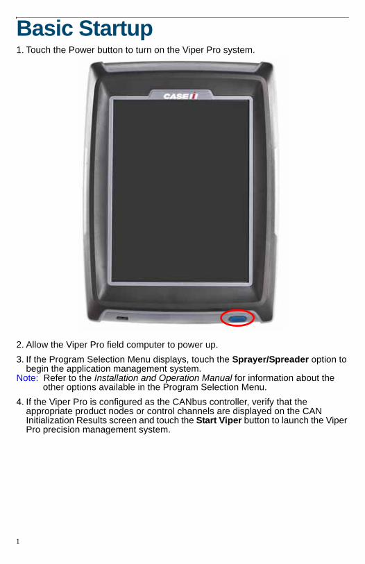
Basic Startup1. Touch the Power button to turn on the Viper Pro system.
2. Allow the Viper Pro field computer to power up.3. If the Program Selection Menu displays, touch the Sprayer/Spreader option to
begin the application management system.Note: Refer to the Installation and Operation Manual for information about the
other options available in the Program Selection Menu.4. If the Viper Pro is configured as the CANbus controller, verify that the
appropriate product nodes or control channels are displayed on the CAN Initialization Results screen and touch the Start Viper button to launch the Viper Pro precision management system.
1
Viper Pro Do’s and Don’ts1. Do have the Viper Pro serial number and firmware revision available when
calling for technical assistance. It is best if the user is in the machine and in front of the Viper Pro when calling for tech support.
2. Do review the manual in its entirety before operating Viper Pro.3. Do power the DGPS receiver and the Raven console or CANBus system
before powering Viper Pro.4. Don’t turn Viper Pro off when in a job, without properly closing the job first. If
the field computer loses power when in a job, part of the information within the job files will not be saved and the associated files may become corrupt.
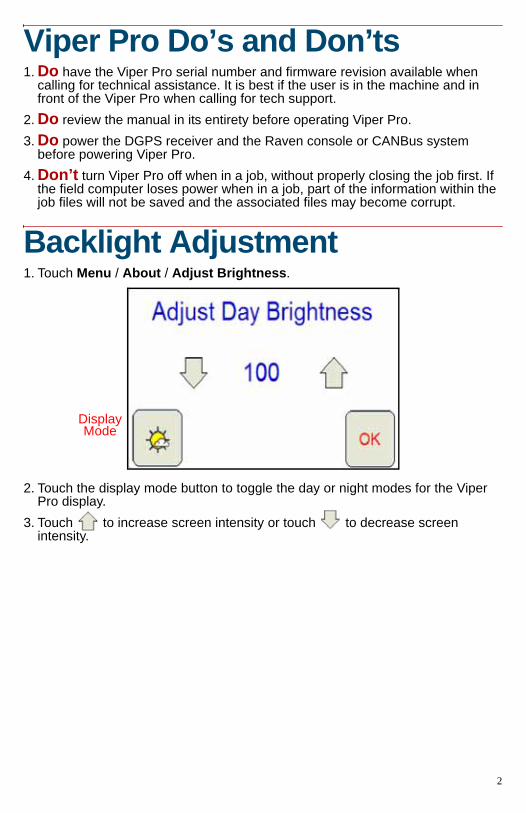
Backlight Adjustment1. Touch Menu / About / Adjust Brightness.
2. Touch the display mode button to toggle the day or night modes for the Viper Pro display.
3. Touch to increase screen intensity or touch to decrease screen intensity.
Display Mode
2
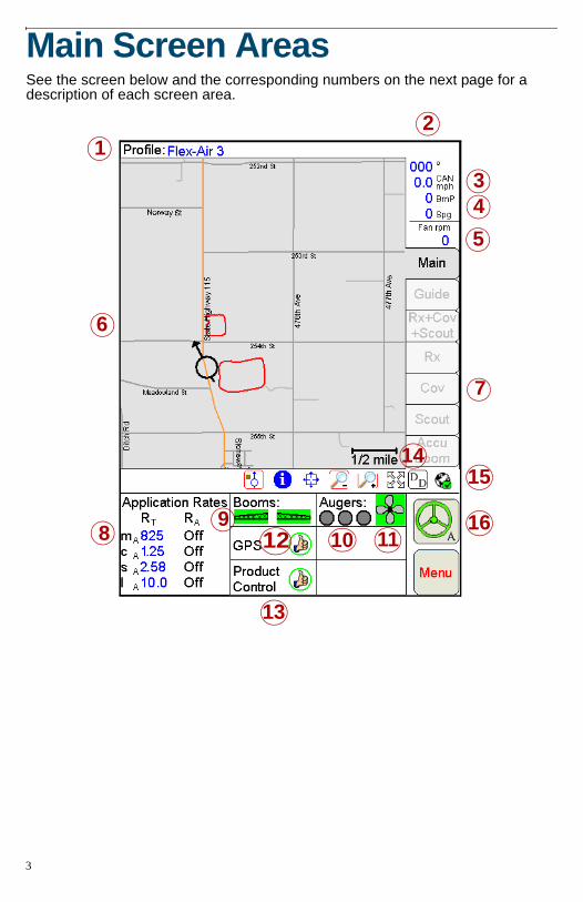
Main Screen AreasSee the screen below and the corresponding numbers on the next page for a description of each screen area.
6
1
43
2
5
10 11
7
98 12
13
14
16
15
3
1. Profile - The machine profile contains configuration settings for specific vehicles, when created by the user.
2. Current Heading - The current heading of the vehicle in compass degrees.3. Speed - The current speed of the vehicle (CAN or GPS).4. BmP and Spg - The current boom pressure and sparge pressure is
displayed if so equipped. If equipped, touch within this area to adjust sparge pressure.
5. Fan RPM - The current speed of the fan is monitored and displayed.6. Map Area - Displays guidance and coverage information associated with the
selected tab.7. Tabs - Used to access available features, functions and screen displays during
a job. The Main tab is available only if a job is not in progress.8. Application Rates - Target rate (RT) and actual rate (RA). Touch in this
area to set or change rates (Available for CAN or serial systems only).9. Booms - The Booms area displays the status of boom or implement sections.
A section display character will display green when on, grey when off. Touch in this area to configure the optional AccuBoom system.
Note: Boom sections controlled by the optional AccuBoom system will display with a blue background.
10.Augers - The current status of the system augers is displayed. Press the area to access the Augers Control screen.
11.Fan Control - The status of the fan is displayed. Touch within this area to access the Fan Control screen.
12.GPS Status Indicator - Status of DGPS messages and the current source of GPS corrections are displayed in this area. Touch this area for additional GPS information.
13.Product Control Status - Product Control Status of a Raven serial console or a Raven CAN system displays in this area. Touch this area to view or modify Product Control settings.
14.Display Data - Touch the ‘DD’ icon to view the status of CAN Tally Registers. Touch the ‘DD’ icon again to hide the data.
15.Wireless Status - If a Slingshot Field Hub™ is connected to the Viper Pro field computer, the status of wireless communications is accessible by touching the wireless communication status indicator.
16.SmarTrax Status Display - If an optional SmarTrax system is installed with the Viper Pro, this area displays the status of SmarTrax system.
4
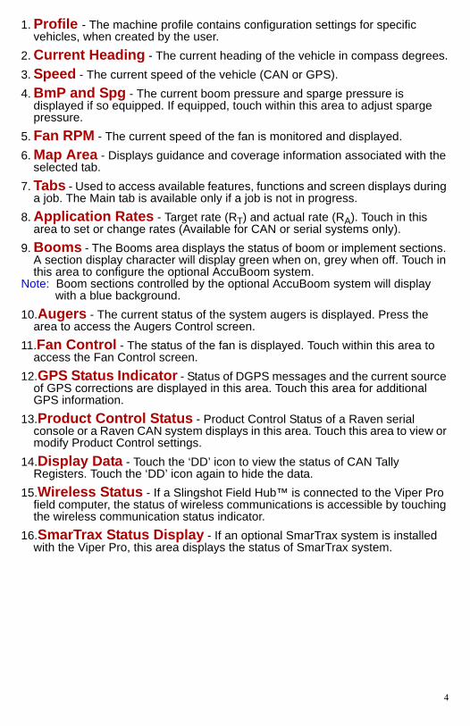
CAN Controller Status Screen AreasSee the screen below and the corresponding sections on the next page for a description of the CAN Controller Status screen.
Note: The CAN Controller Status screen shown above is only displayed if the Viper Pro is configured as the CANbus control console. Review the Viper Pro Installation and Operation Manual for information on configuring the field computer.
6
1
4
3
2
5
7 8
5
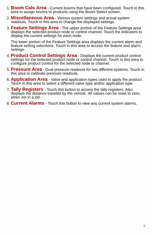
1. Boom Cals Area - Current booms that have been configured. Touch in this area to assign booms to products using the Boom Select screen.
2. Miscellaneous Area - Various system settings and actual system readouts. Touch in this area to change the displayed settings.
3. Feature Settings Area - The upper portion of the Feature Settings area displays the selected product node or control channel. Touch the indicators to display the current settings for each node.The lower portion of the Feature Settings area displays the current alarm and feature setting selections. Touch in this area to access the feature and alarm settings.
4. Product Control Settings Area - Displays the current product control settings for the selected product node or control channel. Touch in this area to configure product control for the selected node or channel.
5. Pressure Area - Dual pressure readouts for two different systems. Touch in this area to calibrate pressure readouts.
6. Application Area - Valve and application types used to apply the product. Touch in this area to select a different valve type and/or application type.
7. Tally Registers - Touch this button to access the tally registers. Also displays the distance traveled by the vehicle. All values can be reset to zero, when not in a job.
8. Current Alarms - Touch this button to view any current system alarms.
6
Screen Icons & SymbolsIcon Name Description
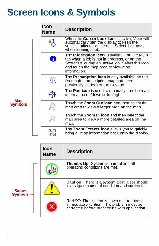
When the Cursor Lock icon is active, Viper will automatically pan the display to keep the vehicle indicator on screen. Select this mode when running a job.The Information icon is available on the Main tab when a job is not in progress, or on the Scout tab during an active job. Select this icon and touch the map area to view map information.The Prescription icon is only available on the Rx tab (if a prescription map had been previously loaded) or the Cov tab.The Pan icon is used to manually pan the map information up/down or left/right.
Touch the Zoom Out icon and then select the map area to view a larger area on the map.
Touch the Zoom In icon and then select the map area to view a more detailed area on the map.The Zoom Extents icon allows you to quickly bring all map information back onto the display.
Icon Name Description
Thumbs Up: System is normal and all operating conditions are met.
Caution: There is a system alert. User should investigate cause of condition and correct it.
Red ‘X’: The system is down and requires immediate attention. This problem must be corrected before proceeding with application.
Map Symbols
Status Symbols
7
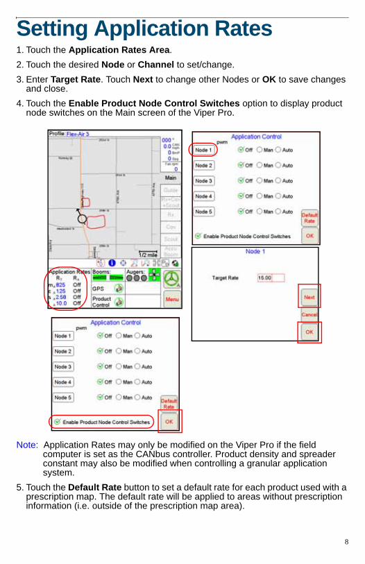
Setting Application Rates1. Touch the Application Rates Area.2. Touch the desired Node or Channel to set/change.3. Enter Target Rate. Touch Next to change other Nodes or OK to save changes
and close.4. Touch the Enable Product Node Control Switches option to display product
node switches on the Main screen of the Viper Pro.
Note: Application Rates may only be modified on the Viper Pro if the field computer is set as the CANbus controller. Product density and spreader constant may also be modified when controlling a granular application system.
5. Touch the Default Rate button to set a default rate for each product used with a prescription map. The default rate will be applied to areas without prescription information (i.e. outside of the prescription map area).
8
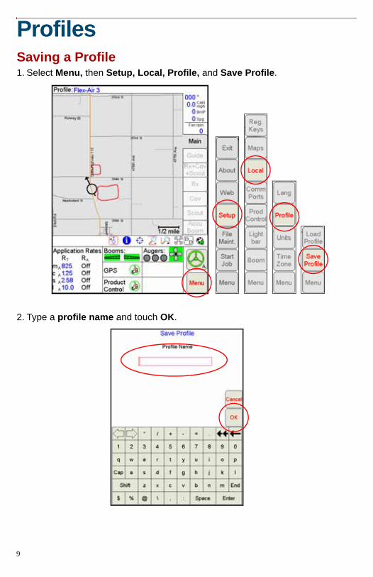
ProfilesSaving a Profile1. Select Menu, then Setup, Local, Profile, and Save Profile.
2. Type a profile name and touch OK.
9
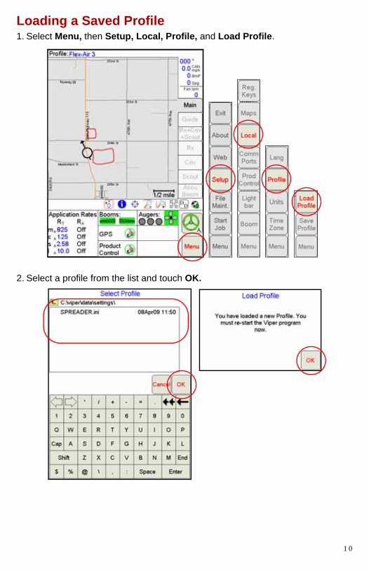
Loading a Saved Profile1. Select Menu, then Setup, Local, Profile, and Load Profile.
2. Select a profile from the list and touch OK.
1 0
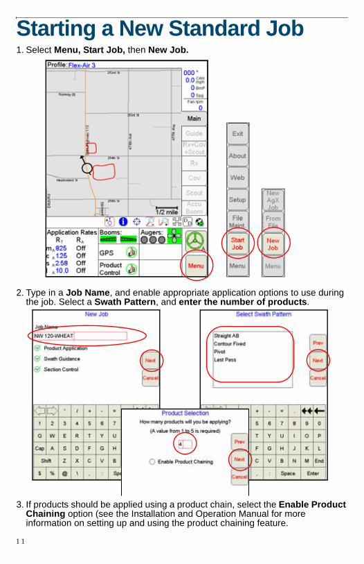
Starting a New Standard Job1. Select Menu, Start Job, then New Job.
2. Type in a Job Name, and enable appropriate application options to use during the job. Select a Swath Pattern, and enter the number of products.
3. If products should be applied using a product chain, select the Enable Product Chaining option (see the Installation and Operation Manual for more information on setting up and using the product chaining feature.
1 1
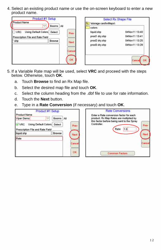
4. Select an existing product name or use the on-screen keyboard to enter a new product name.
5. If a Variable Rate map will be used, select VRC and proceed with the steps below. Otherwise, touch OK.
a. Touch Browse to find an Rx Map file.b. Select the desired map file and touch OK.c. Select the column heading from the .dbf file to use for rate information.d. Touch the Next button.e. Type in a Rate Conversion (if necessary) and touch OK.
1 2
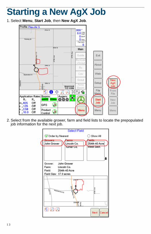
Starting a New AgX Job1. Select Menu, Start Job, then New AgX Job.
2. Select from the available grower, farm and field lists to locate the prepopulated job information for the next job.
1 3
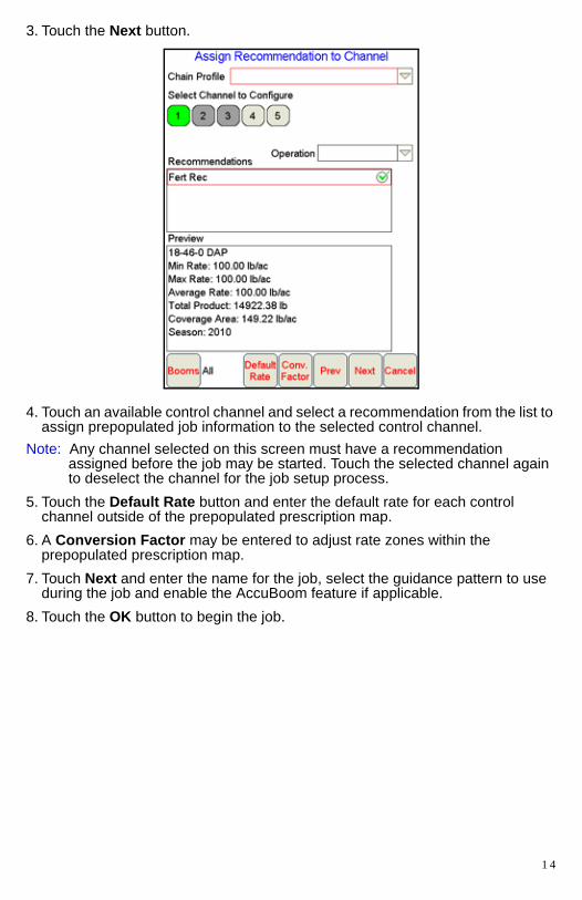
3. Touch the Next button.
4. Touch an available control channel and select a recommendation from the list to assign prepopulated job information to the selected control channel.
Note: Any channel selected on this screen must have a recommendation assigned before the job may be started. Touch the selected channel again to deselect the channel for the job setup process.
5. Touch the Default Rate button and enter the default rate for each control channel outside of the prepopulated prescription map.
6. A Conversion Factor may be entered to adjust rate zones within the prepopulated prescription map.
7. Touch Next and enter the name for the job, select the guidance pattern to use during the job and enable the AccuBoom feature if applicable.
8. Touch the OK button to begin the job.
1 4
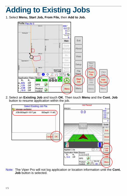
Adding to Existing Jobs1. Select Menu, Start Job, From File, then Add to Job.
2. Select an Existing Job and touch OK. Then touch Menu and the Cont. Job button to resume application within the job.
Note: The Viper Pro will not log application or location information until the Cont. Job button is selected.
1 5
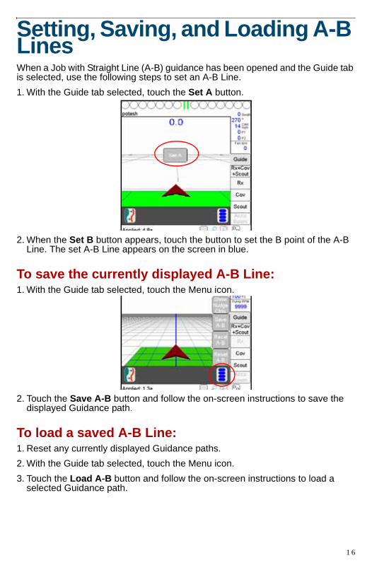
Setting, Saving, and Loading A-B LinesWhen a Job with Straight Line (A-B) guidance has been opened and the Guide tab is selected, use the following steps to set an A-B Line.1. With the Guide tab selected, touch the Set A button.
2. When the Set B button appears, touch the button to set the B point of the A-B Line. The set A-B Line appears on the screen in blue.
To save the currently displayed A-B Line:1. With the Guide tab selected, touch the Menu icon.
2. Touch the Save A-B button and follow the on-screen instructions to save the displayed Guidance path.
To load a saved A-B Line:1. Reset any currently displayed Guidance paths.2. With the Guide tab selected, touch the Menu icon.3. Touch the Load A-B button and follow the on-screen instructions to load a
selected Guidance path.
1 6
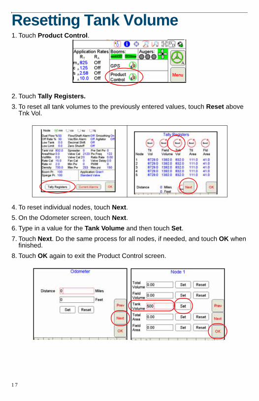
Resetting Tank Volume1. Touch Product Control.
2. Touch Tally Registers.3. To reset all tank volumes to the previously entered values, touch Reset above
Tnk Vol.
4. To reset individual nodes, touch Next.5. On the Odometer screen, touch Next.6. Type in a value for the Tank Volume and then touch Set.7. Touch Next. Do the same process for all nodes, if needed, and touch OK when
finished.8. Touch OK again to exit the Product Control screen.
1 7
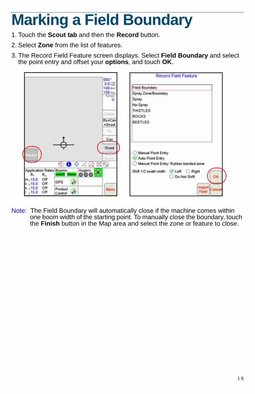
Marking a Field Boundary1. Touch the Scout tab and then the Record button.2. Select Zone from the list of features.3. The Record Field Feature screen displays. Select Field Boundary and select
the point entry and offset your options, and touch OK.
Note: The Field Boundary will automatically close if the machine comes within one boom width of the starting point. To manually close the boundary, touch the Finish button in the Map area and select the zone or feature to close.
1 8
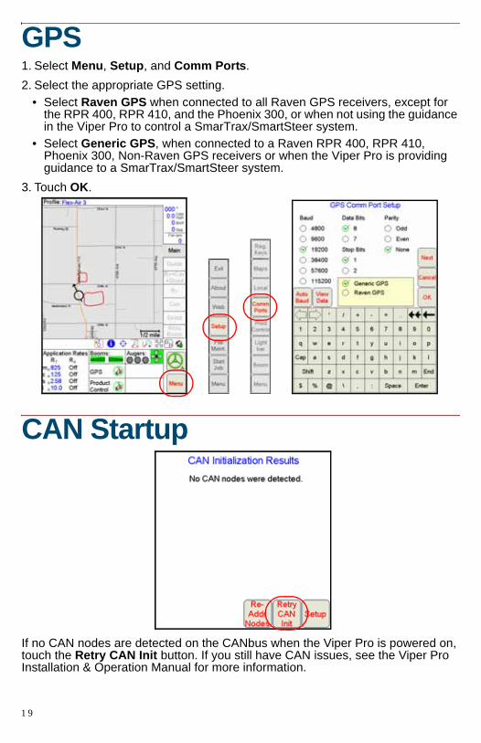
GPS1. Select Menu, Setup, and Comm Ports.2. Select the appropriate GPS setting.
• Select Raven GPS when connected to all Raven GPS receivers, except for the RPR 400, RPR 410, and the Phoenix 300, or when not using the guidance in the Viper Pro to control a SmarTrax/SmartSteer system.
• Select Generic GPS, when connected to a Raven RPR 400, RPR 410, Phoenix 300, Non-Raven GPS receivers or when the Viper Pro is providing guidance to a SmarTrax/SmartSteer system.
3. Touch OK.
CAN Startup
If no CAN nodes are detected on the CANbus when the Viper Pro is powered on, touch the Retry CAN Init button. If you still have CAN issues, see the Viper Pro Installation & Operation Manual for more information.
1 9
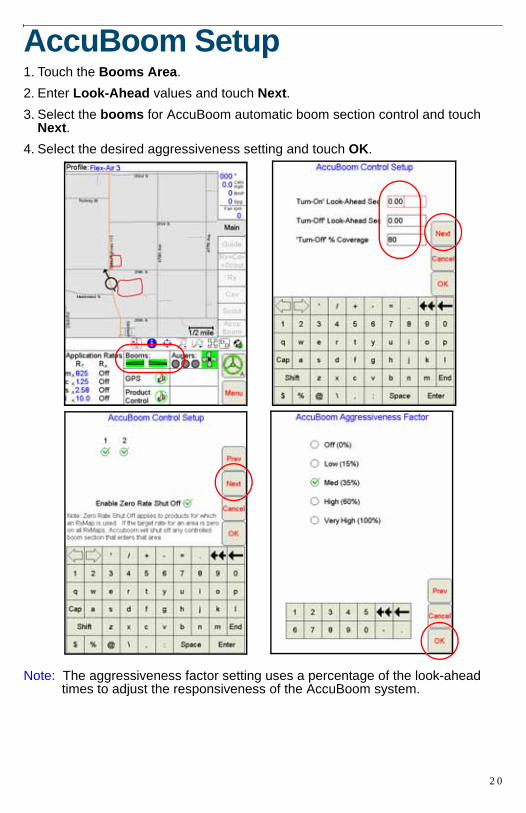
AccuBoom Setup1. Touch the Booms Area.2. Enter Look-Ahead values and touch Next.3. Select the booms for AccuBoom automatic boom section control and touch
Next.4. Select the desired aggressiveness setting and touch OK.
Note: The aggressiveness factor setting uses a percentage of the look-ahead times to adjust the responsiveness of the AccuBoom system.
2 0
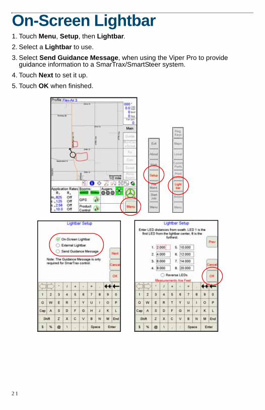
On-Screen Lightbar1. Touch Menu, Setup, then Lightbar.2. Select a Lightbar to use.3. Select Send Guidance Message, when using the Viper Pro to provide
guidance information to a SmarTrax/SmartSteer system.4. Touch Next to set it up.5. Touch OK when finished.
2 1
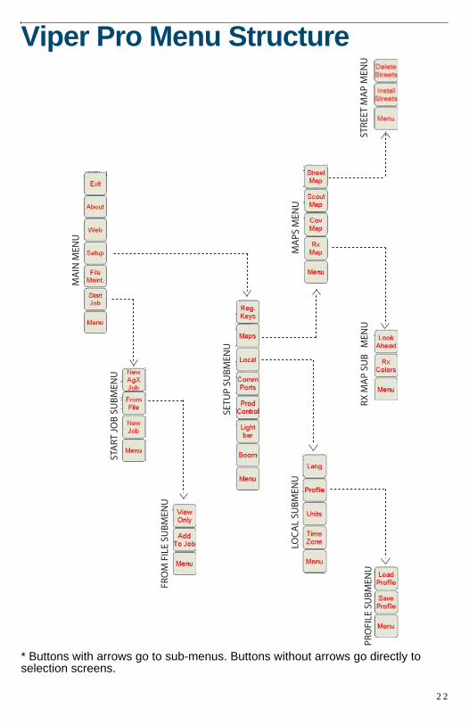
Viper Pro Menu Structure
* Buttons with arrows go to sub-menus. Buttons without arrows go directly to selection screens.
MA
IN M
ENU
STA
RT J
OB
SU
BM
ENU
FRO
M F
ILE
SUB
MEN
U
SETU
P SU
BM
ENU
MA
PS M
ENU
STRE
ET M
AP
MEN
URX
MA
P SU
B
MEN
U
LOC
AL
SUB
MEN
U
PRO
FILE
SU
BM
ENU
2 2