Embed Size (px)
Citation preview

_r" : :
NASA
!
Z
CONTRACTOR
REPORT
by M. Vlajinac,
and N. Pertsas
NASA CR-1932
CASE FILE
ii
i
SUBSONIC AND SUPERSONIC STATIC
AERODYNAMIC CHARACTERIS TICS OF :::
A FAMILY OF BULBOUS BASE CONES
MEASURED WITH A MAGNETIC ..........
SUSPENSION AND BALANCE I SYSTEM
T. Stephel_s, G. Gil!iam,
Prepared byMASSACHUSETTS INSTITUTE OF TECHNOLOGY
Cambridge, Mass. 02139
Jot Langley Research Center
NATIONAL AERONAUTICS AND SPACE ADMINISTRATION " WASHINGTON, D. C. • JANUARY 1972
https://ntrs.nasa.gov/search.jsp?R=19720007334 2018-06-11T02:42:01+00:00Z

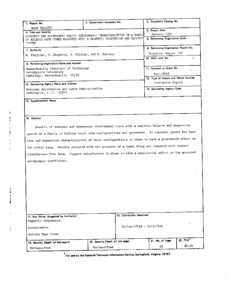
1. Report No. 2. Government Accession No.
NASA CR-1932
4. Titleand Subtitle
SUBSONIC AND SUPERSONIC STATIC AERODYNAMIC CHARACTERISTICS OF A FAMIL
OF BULBOUS BASE CONES MEASURED WITH A MAGNETIC SUSPENSION AND BALANCE
SYSTEM
7. Author(s)
M. VlaJinac, T. Stephens, G. Gilliam, and N. Pertsas
9. P_fmming Or_ni_tion Nameand Address
Massachusetts Institute of Technology
Aerophysics Laboratory
Cambridge, Massachusetts 02139
12. Sponsoring Agancy Name and Addr_s
National Aeronautics and Space Administration
Washington, D. C. 20546
3. Recipient's Catalog No.
5 Report Date
C January 1972
6. Performing Organization Code
8. Performing Or_nization Report No.
Technical Report 166
10. Work Unit No.
11. Contract or Grant No.
NASI-8658
13. Type of Report and Period Covered
Contractor Report
14. Sponsoring Agency Code
15. Supplementary Notes
16. Ab_ra_
Results of subsonic and supersonic wind-tunnel tests with a magnetic balance and suspension
system on a family of bulbous based cone configurations are presented, At subsonic speeds the base
flow and separation characteristics of these configurations is shown to have a pronounced effect on
the static data. Results obtained with the presence of a dummy sting are compared with support
interference free data. Support interference is shown to have a substantial effect on the measured
aerodynamic coefficient.
17. Key Words{Suggested by Authori$)) 18. Di_ribution Statement
Magnetic Suspension
Aerodynamics Unclassified - Unlimited
Bulbous Base Cones
19. Security Clami£(ofthisrepo_) 20. Security Cla_f,(ofthis pega)
Unclassified Unclassified
"For _lebytheN_ionalTechnMallnformation Se_ice, Sprin_ield, Virginia 22151
21. No. of Pages 22. _ice"
65 $ 3-00

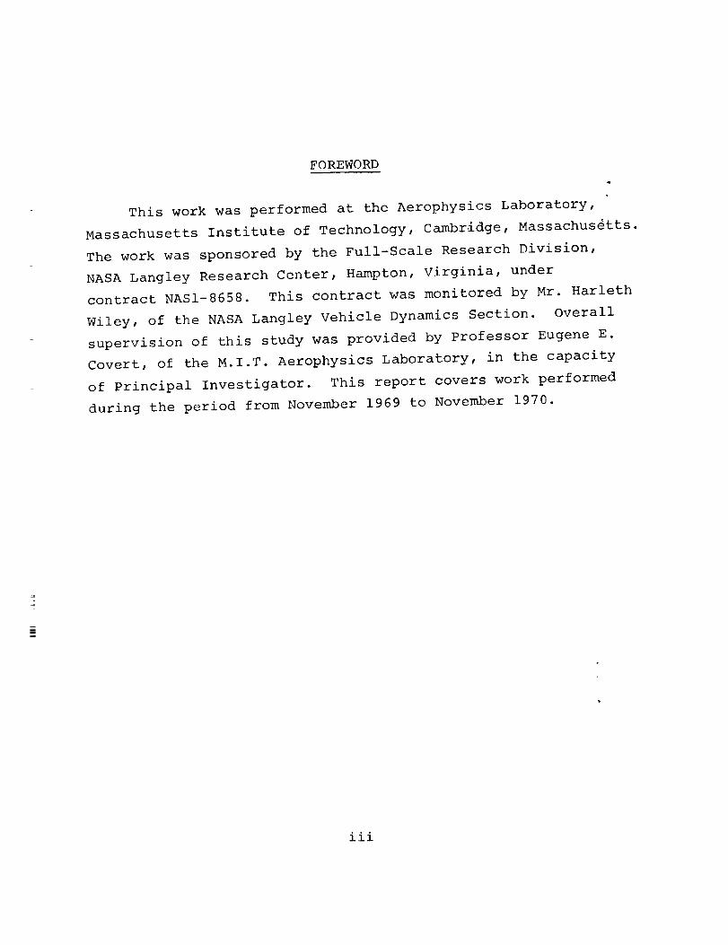
FOREWORD
This work was performed at the Aerophysics Laboratory,
Massachusetts Institute of Technology, Cambridge, Massachusetts.
The work was sponsored by the Full-Scale Research Division,
NASA Langley Research Center, Hampton, Virginia, under
contract NASI-8658. This contract was monitored by Mr. Harleth
Wiley, of the NASA Langley Vehicle Dynamics Section. Overall
supervision of this study was provided by Professor Eugene E.
Covert, of the M.I.T. Aerophysics Laboratory, in the capacity
of Principal Investigator. This report covers work performed
during the period from November 1969 to November 1970.
iii


TABLE OF CONTENTS
iSUMMARY .....................
1INTRODUCTION ....................
APPARATUS ...................... 2
i. Magnetic Balance Description ........ 2
• 32. Supersonic Wind Tunnel .........
3. Subsonic Wind Tunnel ............ 3
4. Model Description ............. 3
4DESCRIPTION OF TESTS ...............
i. Supersonic Tests .......... 4
2. Data Acquisition .............. 4
53. Subsonic Tests ..............
7RESULTS AND DISCUSSION ...............
7i. Supersonic Test Results .........
72. Subsonic Test Results ...........
3. Subsonic Sting Interference Results .... 13
14CONCLUSIONS AI_D RECOMMENDATIONS ...........
17REFERENCES .....................
19TABLES .......................
37FIGURES ......................
V

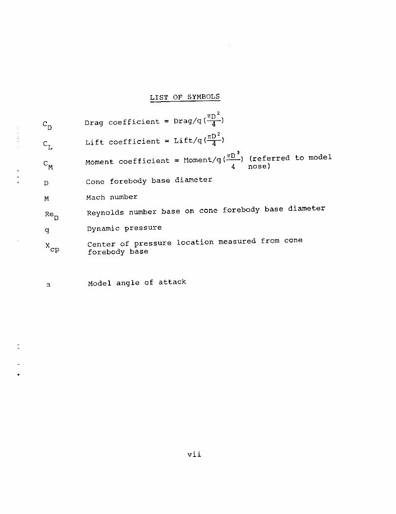
C D
C L
C M
D
M
Re D
q
Xcp
LIST OF SYMBOLS
_D 2
Drag coefficient = Drag/q(-q[--)
Lift coefficient = Lift/q(_)
Moment coefficient = Moment/q(zD--_3) (referred to model4 nose)
Cone forebody base diameter
Mach number
Reynolds number base on cone forebody base diameter
Dynamic pressure
Center of pressure location measured from cone
forebody base
Model angle of attack
vii


SUBSONIC AND SUPERSONICSTATIC AERODYNAMICCHARACTERISTICSOF A FAMILY OF BULBOUSBASE CONESMEASUREDWITH
A MAGNETIC SUSPENSIONAND BALANCE SYSTEM
By M. Vlajinac, T. Stephens, G. Gilliam, N. PertsasMassachusetts Institute of Technology
SUMMARY
Aerodynamic tests were conducted on a blunted 6° half
angle cone forebody with a series of bulbous bases. Static
force and moment data were obtained both at subsonic and
supersonic speeds using the M.I.T.-N.A.S.A. prototype magnetic
suspension and balance system.
The subsonic static data obtained on these configurations
in some cases showed anomalous variation of the aerodynamic
coefficients with angle of attack, particularly near zero.
Also, under some conditions, hysteresis-type variation of
the force and moment coefficients was observed, and was
usually associated with appreciable unsteady aerodynamic
loading of the model. A substantial change in the magnitude
of the force and moment coefficients was observed after addition
to the forebody of a circumferential boundary layer trip wire.
Tests were conducted to evaluate the effect of a dummy
sting in the vicinity of the model base. The results show
a pronounced decrease in the measured drag coefficient due to
the presence of the sting.
The anomalous behavior of the subsonic aerodynamic
characteristics is believed to be caused by irregular separa-
tion on the bulbous bases. The behavio_ which exhibits both
non-linearity and hysteresis, can have a significant effect
on the stability of such configurations. Since separation
appears to be very sensitive to the base flow process, it is
concluded that freedom from support interference is desirable
for this class of models.
INTRODUCTION
The static and dynamic characteristics of entry-type
configurations are often affected by flow separation on the1

body base (ref. i). In some cases, the flow separation can
cause negative damping of the body motion, or energy extrac-tion from the flow, leading to dynamic instability. In
addition to this, the location of the separation point can be"path dependent" causing a hysteresis behavior in the static
coefficients as well as affecting the damping characteristics
of the body. Wind tunnel tests on bulbous base cone configura-
tions using conventional sting support for the models have
shown the measured aerodynamic data to be strongly affected by
sting interference on the surrounding flow (ref. 1,2). A
practical method for obtaining interference-free aerodynamic
data is by the use of a magnetic suspension and balance
system. Development of such systems have been carried on at
the M.I.T. Aerophysics Laboratory.*
APPARATUS
i. Magnetic Balance Description. - The magnetic balance
used in these tests is described in detail in Ref. 3. The
balance is presently capable of magnetically suspending a
variety of ferromagnetic model geometries and measuring five
components of force and moment on the model. (Rolling
moments are not measured.) The forces and moments on the
model are computed from the measured magnet coil currents
required to balance the aerodynamic and gravity loads. The
measured magnet currents, tunnel conditions and model position
data are processed by a computer program which reduces the
data to aerodynamic coefficient form. The data reduction
The original development work at M.I.T. was sponsored by the
Aerospace Research Laboratories, Wright-Patterson A.F.B., and
a working system, which is still in use, was built. Further
development work was sponsored by the NASA-Langley Research
Center, and an improved magnetic suspension system was built.
This system is referred to as the M.I.T.-N.A.S.A. Prototype
Magnetic Suspension and Balance System.
2
techniques developed for this balance are discussed in detail
in Ref. 4.
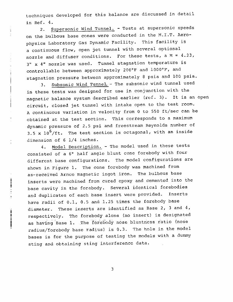
2. Supersonic Wind Tunnel. - Tests at supersonic speeds
on the bulbous base cones were conducted in the M.I.T. Aero-
physics Laboratory Gas Dynamic Facility. This facility is
a continuous flow, open jet tunnel with several optional
nozzle and diffuser conditions. For these tests, a M = 4.23,
3" x 4" nozzle was used. Tunnel stagnation temperature is
controllable between approximately 200°F and 1000°F, and
stagnation pressure between approximately 8 psia and i00 psia.
3. Subsonic Wind Tunnel.- The subsonic wind tunnel used
in these tests was designed for use in conjunction with the
magnetic balance system described earlier (ref. 3). It is an open
circuit, closed jet tunnel with intake open to the test room.
A continuous variation in velocity from 0 to 550 ft/sec can be
obtained at the test section. This corresponds to a maximum
dynamic pressure of 2.5 psi and freestream Reynolds number of
3.5 x 10⁶/ft. The test section is octagonal, with an inside
dimension of 6 1/4 inches.
4. Model Description. - The model used in these tests
consisted of a 6 ° half angle blunt cone forebody with four
different base configurations. The model configurations are
shown in Figure i. The cone forebody was machined from
as-received Armco magnetic ingot iron. The bulbous base
inserts were machined from cured epoxy and cemented into the
base cavity in the forebody. Several identical forebodies
and duplicates of each base insert were provided. Inserts
have radii of 0.i, 0.5 and 1.25 times the forebody base
diameter. These inserts are identified as Base 2, 3 and 4,
respectively. The forebody alone (no insert) is designated
as having Base i. The f0rebody nose bluntness ratio (nose
radius/forebody base radius) is 0.3. The hole in the model
bases is for the purpose of testing the models with a dummy
sting and obtaining sting interference data.

DESCRIPTION OF TESTS
i. Supersonic Tests. - Wind tunnel tests were conducted
on the family of bulbous base cones to obtain static force and
moment coefficients at Mach 4.23.* The nominal tunnel conditions
throughout these tests were a stagnation absolute pressure of
25.0 psi, and a stagnation temperature of 300°F. Data were
obtained on these models over an angle of attack range from
-4 ° to +8 ° in nominal increments of 2 ° .
2. Data Acquisition. - The static forces and moments
were obtained by measuring the magnet coil currents required
to balance gravity and aerodynamic loads on the models. The
magnet currents were measured with an integrating digital
voltmeter. Integration (averaging) period for each current
measurement was 10 seconds. The 10 second sampling attenuates
the effects of ripple and noise and provides an accurate
average of the coil current from which the steady state loads
on the model can be obtained. Voltmeter readings were
recorded with a digital printer.
The model position with respect to the wind tunnel axis
was visually monitored and set with three transits. The
model absolute position and orientation were measured to the
following estimated accuracy:
Translations (lift, drag, slip): ±0.001 in.
Angles (pitch, yaw): ±0.i °.
Attempts were made to measure the effect of a dummy sting
on the measured coefficients in the course of the super-
sonic tests. However, the dummy sting apparently interfered
with the tunnel starting process to such a degree that
controlled suspension of the model was lost for all starts
that were attempted with the sting present. In all cases,
control was lost in the side force channel. This channel
has the lowest power capability and, consequently, the
poorest transient response. Blocking tests, however, showed
that the model-sting combination would not block the tunnel.
4
The procedures used for each data point were the following:i. The desired model position and orientation with respect
to the tunnel were indexed on the transits. The model was
then translated and rotated to this position with the magnetic
balance position control (see ref. 3).2. The wind tunnel stagnation pressure and temperature
were recorded.
3. The six magnet currents were sampled for 10 seconds
each and recorded.
4. The model position was checked to insure no change
in position had occurred.5. The transits were indexed for the next model position
and the procedure returned to step i.
A similar procedure as outlined above was repeated wind-
off, with the omission of step 2, at each model position forwhich wind-on data had been taken. This provided the tare
currents which are required in the data reduction process.
The resulting magnet currents, model position and tunnel
conditions were processed by a computer program to reduce the
data to aerodynamic coefficient form (see ref. 4).
3. Subsonic Tests. - Wind tunnel tests were conducted on
the same bulbous base cone configurations at subsonic speeds.
The nominal tunnel conditions for these tests were a dynamic
pressure of 0.830 psi and a Mach number of 0.28. The nominal
Reynolds number based on the cone forebody base diameter was
1.2 x 10⁵. The angle of attack range was from -6 ° to +12 ° in
nominal increments of 2 ° . AdditiOnal data points were taken
in smaller angle increments where it was necessary to explore
in greater detail anomalous variation of the coefficients
with angle of attack.
Continuous plots of magnet currents versus angle of attack
were made on an x-y plotter. The Electromagnetic Position
Sensor (see ref. 3) signal was Used t0 provide the model anqle
of attack in these plots. The model angle of attack was varied
over the desired range by rotating the magnetic balance pitch
position control. Since the position controls are effectively
5

decoupled, the resulting model motion was an angle of attack
sweep in the pitch plane. The position sensor signal was then
calibrated using the transits as an accurate angle reference.
This technique proved useful particularly where non-linear and
unsteady behavior of the forces and moments with angle of
attack occurred. Discrete data points could obscure such
behavior.
Static data at similar tunnel conditions were obtained
with the four cone configurations with a circumferential
boundary layer trip wire on the cone forebody surface. The
trip consisted of a 0.017 in. diameter copper wire, in all
cases located 1.75 in. from the base of the model forebody
(see Fig. I). The trip produced a turbulent boundary layer
flow over the rear of the forebody, and turbulent separation
from the base. These tests were performed since it is
believed that the non-linear behavior of the static coefficients
with angle of attack were primarily caused by laminar boundary
layer separation from the model bases. In addition, the
unsteady aerodynamic loads on the model were attributed to
unsteadiness in the location of the separation point.
Attempts were made to obtain the aerodynamic damping-in-
pitch coefficients for the bulbous base cones using a forced
oscillation technique (ref. 4). The current amplitude required
to force the model motion at its resonant frequency was more
than 80 db below its off-resonance value, indicating a
damping ratio of less than 4 x 10 -5 Tests performed on all
four model configurations exhibited similar results. It
became evident from these results that improvements in
signal-to-noise ratio are required before this technique can
be used successfully to measure small damping moments.
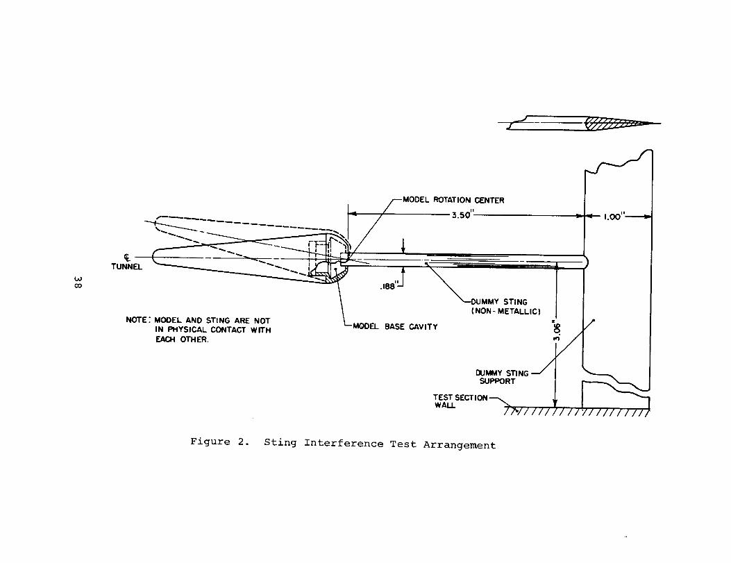
In addition to the above tests, static data on the base
3 configuration (see Fig. i) were taken with a dummy sting
attached to the wind tunnel walls and extending into the base
cavity of the model. An illustration of the sting arrangement
is shown in Figure 2. Since the sting was fixed to the tunnel

walls, the point of rotation of the model was about the modelbase and on the tunnel axis, thereby maintaining the sting
centrally located in the base cavity. This point of rotation
differed from that used in the remainder of the tests. The
model was pitched in those cases about a point on the modelsurface, one base diameter from the base of the cone forebody,
since the transits used for setting the model absolute
position and orientation sight on the edge of the model and
it is desirable to rotate the model about a point near the
geometrical center of the balance.
RESULTS AND DISCUSSION
i. Supersonic Test Results. - The measured static
coefficients and center of pressure location obtained at Mach
4.23 on the four cone models are shown in Table I. The drag
data were corrected for horizontal tunnel bouyancy, which was
less than 0.3% of the measured drag at zero angle of attack.
The measured drag and lift coefficient for the four
models versus angle of attack are shown in Figures 3 and 4,
respectively. The figures show the addition of the bulbous
bases to have little influence on the lift and drag of these
models. The pitching moment coefficient, however, shown in
Figure 5, indicates a slight stabilizing moment coefficient
variation with angle of attack as the base size is increased.
The angular offset in the lift and pitching moment curves
(Figs. 4,5) are due to flow misalignment and curvature along
the tunnel axis. The data was not corrected fer this effect.
It is concluded that the bulbous bases have only a small
effect on the static characteristics at Mach 4.23, with a
slight increase in static stability with increasing base size.
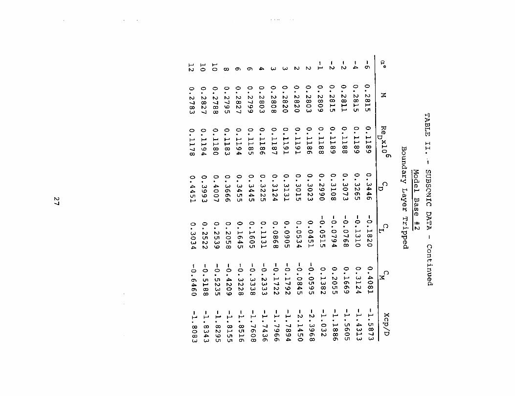
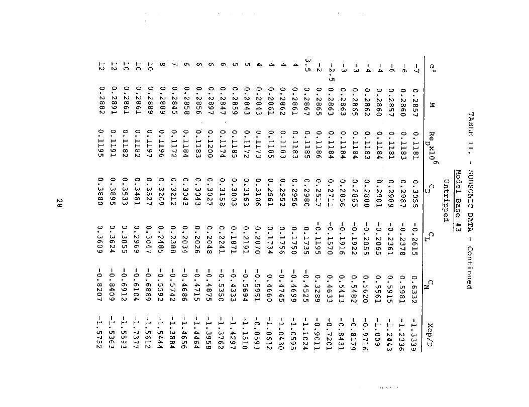
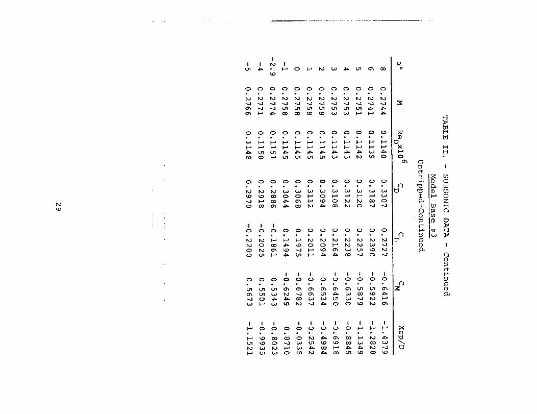
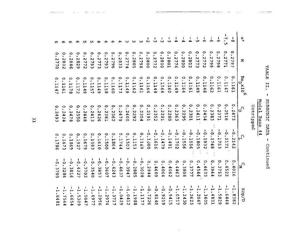
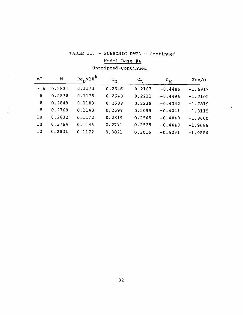
2. Subsonic Test Results. - The measured static coefficients
and center of pressure location for the bulbous based cones
obtained at a nominal Mach number of 0.28 are shown in Table 2.
The coefficients were corrected for tunnel blockage effects
(ref. 5). The data represent tests both with and without the
use of the forebody boundary layer trip wire and is so
designated in the tables. Results obtained with and without
the boundary layer trip indicate that at the Reynolds number
used in these tests (120,000), the flow near the model base
was laminar or near transition in the untripped case. At the
same Reynolds number, the addition of the boundary layertrip created a turbulent boundary layer over the rear portionof the model based on calculations in ref. 5.
The lift coefficient versus angle of attack for the
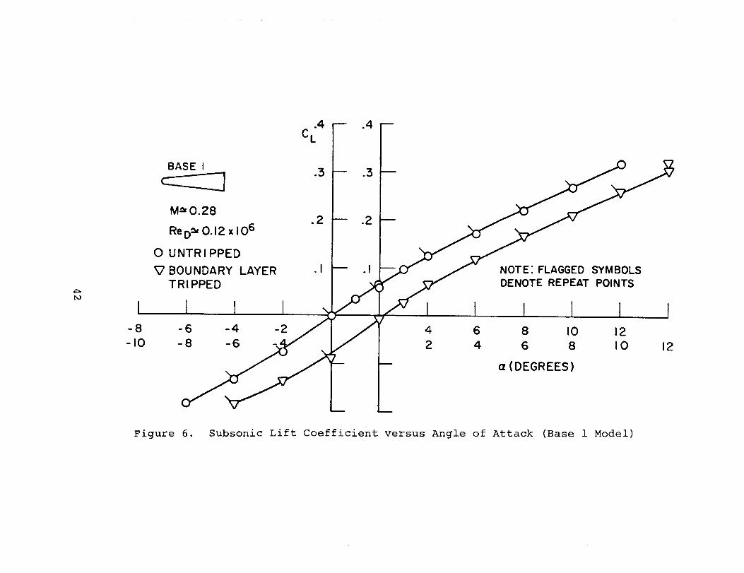
model 1 configuration (flat base) is shown in Figure 6 for
both the tripped and untripped cases. The boundary layer
trip appears to have little effect on the lift coefficient.
The drag coefficient versus angle of attack is shown in
Figure 7 for the same model configuration. The effect of the
trip is to increase the drag coefficient over the untripped
case and is assumed to be due to both the drag of the trip and
increased skin friction over the rear portion of the model,
since the separation point is governed by the sharp corner at
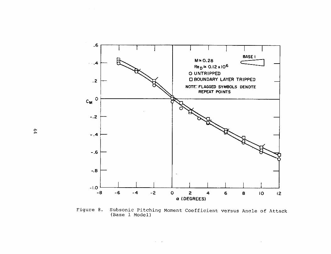
the base. The moment coefficient versus angle of attack for
the Base 1 configuration is shown in Figure 8. The moment
coefficient variation with angle of attack appears to be
unaltered with the addition of the trip, though a tare angle
of attack of approximately +0.3 degrees appears in the tripped
case. Close examination of the lift and drag coefficient
(Figs. 6, 7) indicates the presence of a tare angle of attack
of similar magnitude in the case of the tripped model. This
tare angle appears in the remaining data which were taken
subsequent to the above tests and may be due to an angular
misalignment of the pitch-monitoring transit with the test
section flow direction.
The lift coefficient versus angle of attack for the Base 2
model configuration is shown in Figure 9. In contrast to the
Base 1 results, an anomalous behavior of the lift coefficient
near zero angle of attack is observed in the untripped case.
In addition, the scatter in the data near zero angle of attack
indicates unsteady aerodynamic forces on the model are present.
8

Though the forces were obtained by samplinq the magnet currentsfor i0 seconds (see description of tests), the scatter in the
repeat data indicates that the fluctuating forces are eitherrandom or have a considerably longer time constant than 10
seconds, or both. The unsteady aerodynamic loads on the model
were verified by visually observing the model motion. The
movement of a magnetically suspended model is the result of
unsteady loads on the model whose magnitude and frequency
are beyond the present control range of the magnet power
amplifiers. If the unsteady loads on the model are of sufficient
magnitude and frequency, a loss of magnetic model suspension
occurs. This was exemplified during the Base 2 model tests
with the addition of the boundary layer trip ring. Though the
lift coefficient appears to be more linear with angle of attack
than in the untr_pped case (Figure 9), no data could be taken
at or near zero angle of attack due to model instability.
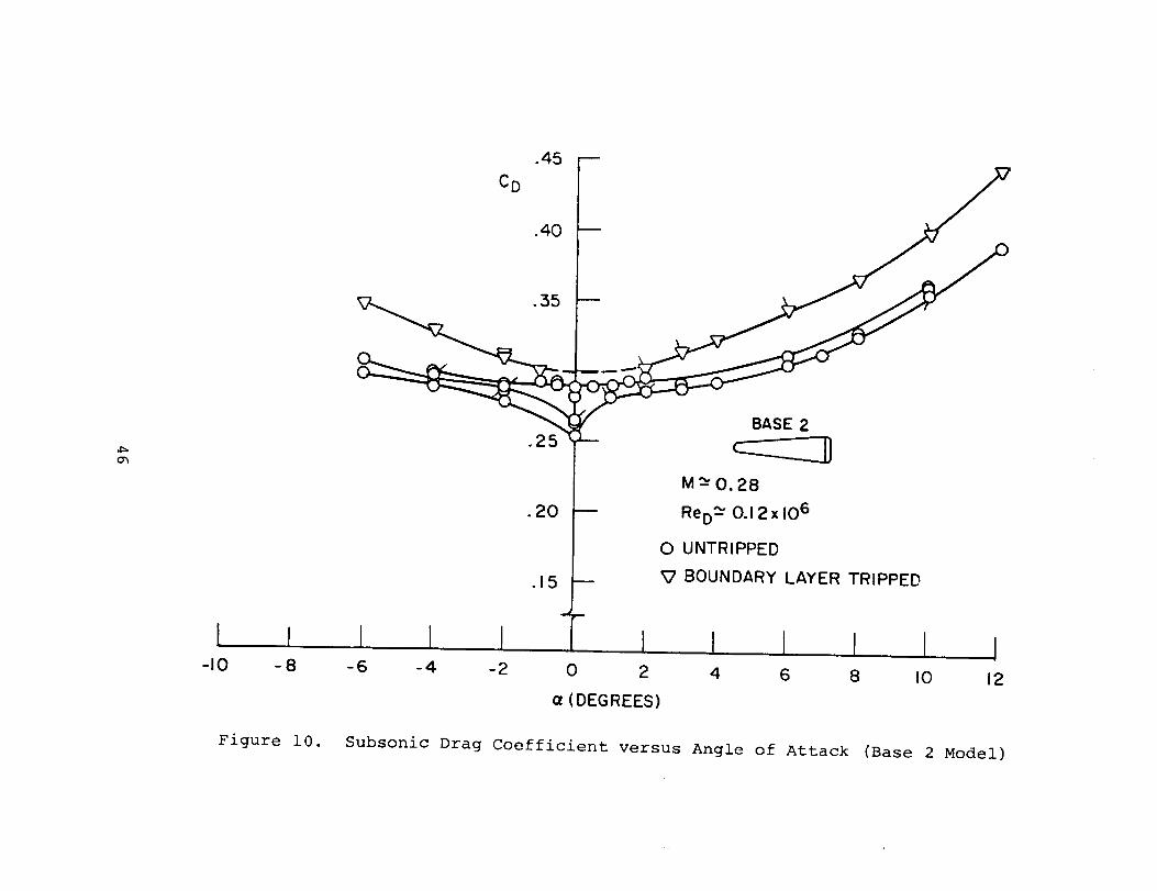
The drag coefficient versus angle of attack for the
Base 2 model is shown in Figure I0. In the case of the
untripped model, the measured drag coefficient has a non-
repeatable character which appeared to be dependent on the
sequence in which the data were taken. The various curves in
Figure i0 for the untripped model are drawn to indicate the
various curves that were generated during the data acquisition.
This indicates the model base flow could be in transition and
the location of the separation point on the base could be
unsteady and dependent on the previous model history (path
dependence or hysteresis). For the case of the tripped Base 2
configuration, the drag coefficient appears to be constant
at a given angle of attack and does not exhibit a path-dependent
behavior. However, in the case of the tripped model, the
suspension instability caused by the fluctuating aerodynamic
loads prevented data from being taken near zero angle of attack.
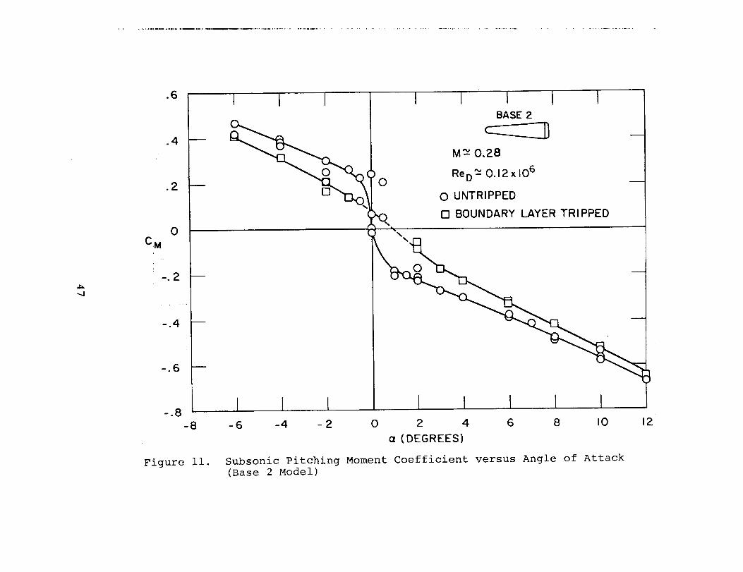
The pitching moment variation with angle of attack for the
Base 2 configuration is shown in Figure ii. Similar to
the behavior of the lift and drag coefficient of this model
with angle of attack, a non-linear and path dependent moment is

observed in the untripped case. The effect of the trip is seen
to reduce the non-linearity of the moment coefficient with
angle of attack, when compared with the untripped results.
The present results and observations during the tests
of the Base 2 model led to the conclusion that in the case
of laminar (or transition) base flow, the unsteady aerodynamic
loads are a hysteresis type which, when averaged over 10
seconds, do not produce an "average" force which is independent
of the direction in which the data are taken. In contrast
to the laminar case, the unsteady aerodynamic loads with a
turbulent base flow are such as to result in repeatable loads
when averaged over i0 seconds and which are path independent.
The associated model motion appeared to be of smaller magnitude,
but higher frequency than in the laminar case. In the case
of the turbulent base flow at and near zero angle of attack,
the unsteady aerodynamic forces prevented data from being taken.
The model instability near zero angle of attack for the
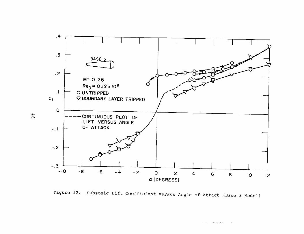
Base 3 model configuration was even more pronounced than in
the previous model (Base 2). The lift coefficient versus
angle of attack is shown in Figure 12. The untripped model
exhibited a path dependence of the lift coefficient with
angle of attack similar to the Base 2 drag coefficient
behavior (Figure i0). Data points taken in a sequence
(indicated by arrows) appear to follow separate paths at the
lower angles of attack and coalesce at the higher angles of
attack. Due to the instability near zero angle of attack, the
wind tunnel flow had to be started with the model pitched above
4 ° . An unusual run was obtained with the model at 8 ° during
the tunnel start. In this particular sequence, data were
taken at continuously decreasing angles of attack to -i°;
at which point the loss of magnetic suspension of the model
occurred. The large positive values of lift coefficient at and
near zero angle of attack should be noted as this reflects a
"hysteresis"-type behavior.
A technique was used to obtain a continuous plot of lift
coefficient versus angle of attack for the untripped Base 3
10

configuration in the angle of attack range from -2 ° to +4 ° .
In this region, if a given average angle of attack is maintained,
the unsteady aerodynamic loads produce model movements which
diverge and cause loss of magnetic suspension control. Also,
an accurate model angle of attack cannot be set with the
transit. The technique employed to obtain an average lift
force and angle of attack of the model involved pitching the
model from positive to negative angles of attack at a sufficiently
rapid rate (_0.2°/sec) to prevent the unsteady aerodynamic
loads on £he model from amplifying the motion and causing loss
of model suspension (see section on subsonic test description).
The resulting curve (dashed line in Figure 12) represents the
average lift coefficient versus average angle of attack since
both the measured force (proportional to lift magnet current)
and model position signals were low-pass filtered to remove
the unsteady portion of the signal. The results appear to be
hysteresis free since an identical curve was generated by
sweeping the model angle from positive to negative and vice-
versa. A tentative explanation for the absence of hysteresis
is the effect of the superimposed unsteady motion, analogous
to the demagnetization of a magnetic material by means of an
alternating field. During this test, considerable model motion
was observed as the model angle of attack went through zero.
In contrast to this behavior, the curve indicating the hysteresis
behavior of the lift coefficient with angle of attack (Fig. 12),
the model motion viewed through the transits was imperceptible
including the point at -i °, indicating a stable flow separation
location.
The data obtained on the Base 3 model with the boundary
layer trip ring are also shown in Figure 12. The lift
coefficient in this case appears more linear with angle of
attack than in the untripped case and did not exhibit a
hysteresis behavior. The model instability near zero angle
of attack, as in the Base 2 tests with the boundary layer
tripped, prevented data from being obtained in this region.
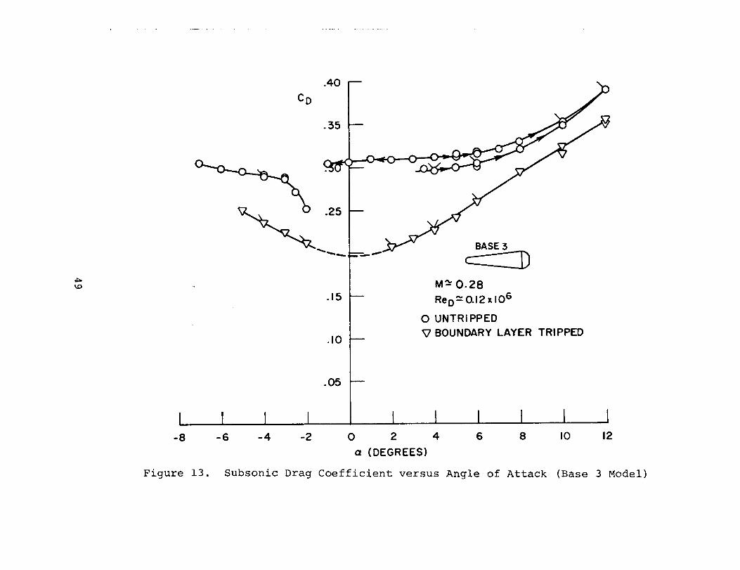
The drag coefficient versus angle of attack for the Base
ii

3 configuration is shown in Figure 13. In contrast to the
results of the Base 1 and Base 2 results, the effect of the
boundary layer trip is to reduce the drag coefficient over
the untripped case. Since Base 3 is spherical, this effect is
analogous to the classical result of drag reduction on a sphere
by tripping the boundary layer and thereby shifting the separationpoint aft of the laminar case. Similar to the lift coefficient
behavior for this model, the drag coefficient in the untripped
case exhibited a path dependence. One curve obtained at
negative angles of attack appears to tend towards the drag
in the turbulent case, thus indicating the base flow could be
in transition. The drag data corresponding to the run where a
large lift coefficient was obtained at or near zero incidence
(Fig. 12) appear to be nearly constant with angle of attack
in this region.
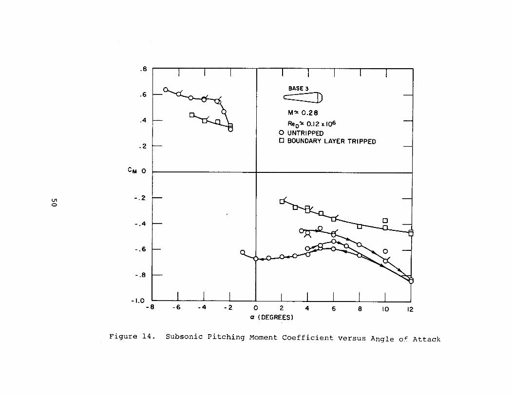
The moment coefficient versus angle of attack for the
Base 3 model is shown in Figure 14. The moment is referred
to the nose of the model and thus reflects the anomalous behavior
of the lift and drag coefficient for this model configuration.
The lift coefficient versus angle of attack for the Base
4 configuration is shown in Figure 15. The untripped model
results indicate similar path-dependent behavior of the lift
coefficient with angle of attack as in the Base 2 and Base 3
cases. The model instability at small angles of attack
prevented data from being taken in these regions. Continuous
data through zero angle of attack could not be obtained as with
the Base 3 model due to the larger unsteady aerodynamic loads
generated on this configuration. A marked reduction in lift
was obtained with the addition of the boundary layer trip,
accompanied by a marked improvement in model suspension
stability. The increased model stability permitted data to
be taken with the model at and near zero angle of attack.
The addition of the trip also produced a large reduction
in the drag coefficient on the Base 4 model and is shown in
Figure 16. The untripped data are seen to have the path-
dependent behavior which characterized the results with the
smaller bulbous bases.
12

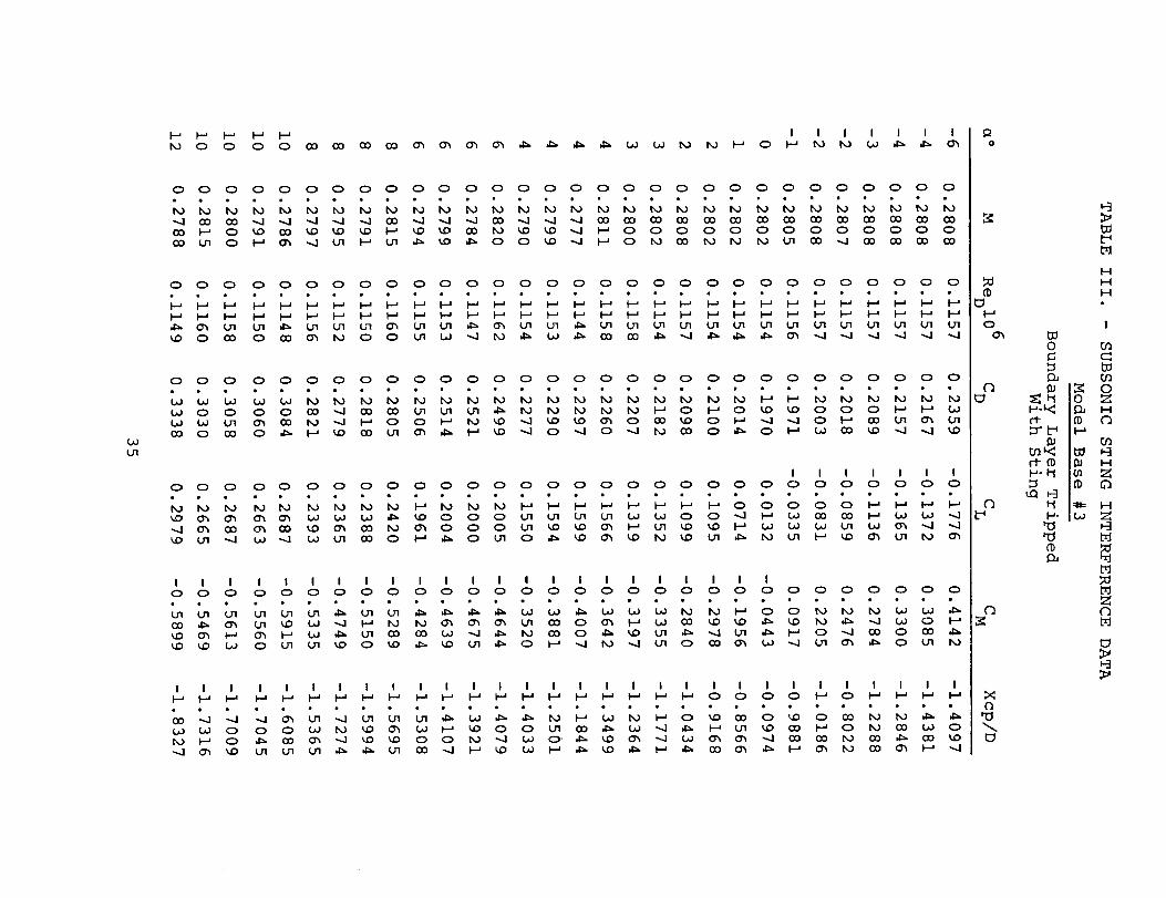
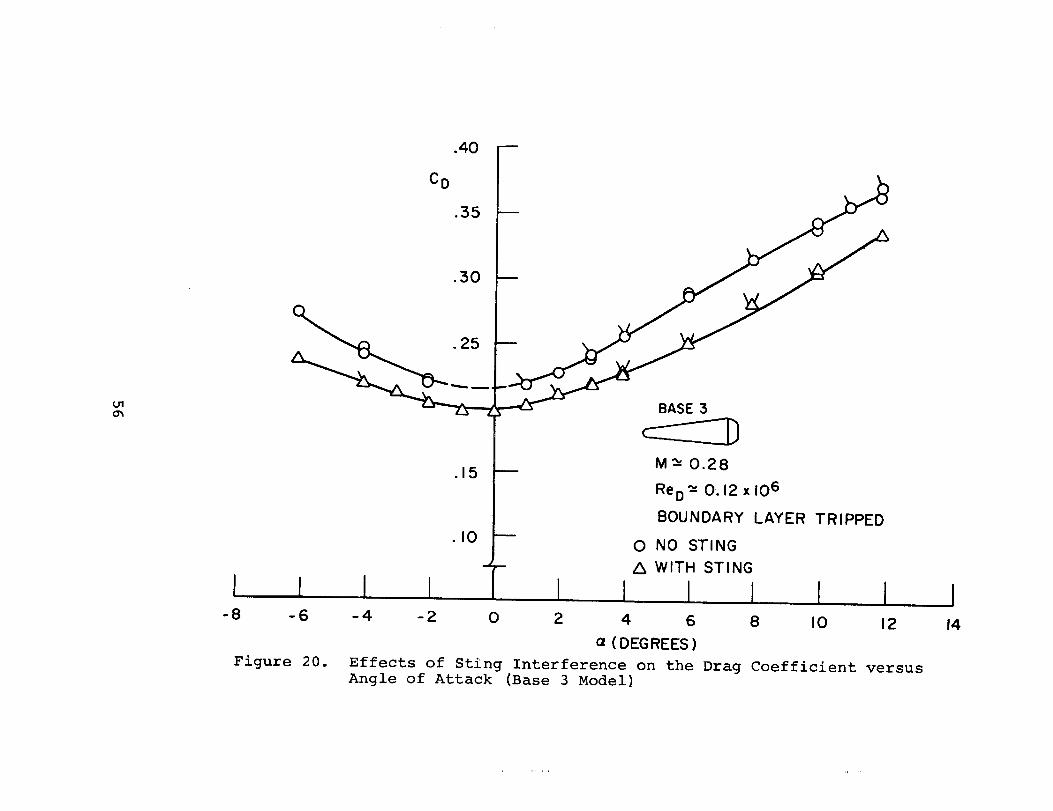
3. Subsonic Stin_ Interference Results. - The static
characteristics of the bulbous base cones have been shown to
be affected by the nature of the flow over the rear portion of
the model. Tests were performed on the Base 3 model to determine
the effects of a dummy sting on the measured aerodynamic
parameters and are described in an earlier section. The
boundary layer trip ring was used on the model and identical
tests were performed with and without the presence of the sting.
The sting interference test results are shown in Table 3.
The effect of the sting on the lift coefficient versus
angle of attack is shown in Figure 19. The presence of the
dummy sting is seen to have a more pronounced effect at the
larger angles of attack. Of particular interest was the marked
increase in model stability observed near zero angle of attack
with £he sting present. This fact permitted data to be taken
at and near zero angle of attack, whereas it had been impossible
to obtain data in this region without the sting.
A considerable change in the drag coefficient was
observed due to the addition of the dummy sting and is shown in
Figure 20. These data again reflect the increased model
stability with the addition of the sting permitting data to
be taken at zero angle of attack.
A small discrepancy corresponding to a shift in angle
of attack (0.8 ° ) was observed when comparing the data
obtained during the sting interference tests with the previously
discussed results. The cause of this discrepancy is not fully
understood at present and is believed to be related to the
different rotation point of the model with respect to the
tunnel walls, which was discussed earlier.
Comparison of the present data using a magnetic suspension
system and data obtained in ref. 1 are shown in Figure 21.
Though the Mach number in the two cases is approximately the
same, the Reynolds number is an order of magnitude different.
However, the agreement is good particularly in the non-linear
region near zero angle of attack. The present results indicate
13
that the sting interference is sufficient to account for thedisagreement between the two, and is in accord with the
conclusions regarding model support interference on bulbous
base cones in both references 1 and 2.
CONCLUSIONS AND RECOMMENDATIONS
Wind tunnel tests at both subsonic and supersonic speeds
were conducted on a blunted 6 ° half angle cone with various
bulbous bases using a magnetic suspension and balance system.
From the results of these tests, the following were concluded:
i) At supersonic speeds (M=4.23), the addition of bulbous
bases to a blunted 6 ° half angle cone has little effect on the
measured static coefficients.
2) At subsonic speeds, the addition of bulbous bases
to the cone forebody produces anomalous behavior of the static
coefficients with angle of attack particularly where the base
flow is laminar or in transition.
3) The addition of a boundary layer trip on the cone
forebody increases the linearity of the lift and pitching
moment coefficients with angle of attack and causes pronounced
changes in the drag coefficient of the bulbous based cones.
These changes are believed due to the separation characteristics
on the base of the model.
4) The model motion observed at and near zero angle of
attack is due to unsteady aerodynamic loads on the bulbous bases.
5) Hysteresis or path dependent behavior of static
coefficients with angle of attack was observed on the bulbous
base models with laminar or transition base flow. This
phenomenon was not observed in the cases where the base flow
was turbulent.
6) A marked change in static stability was observed
with the largest bulbous base (Model 4) with turbulent flow
over the model base. This was accompanied by a reduction in
both the lift and drag coefficient compared to the laminar
flow case.
14

7) Sting interference effects were measured and found
to have considerable influence on the static coefficients.
This is in agreement with conclusions regarding sting inter-
ference on bulbous base cones discussed elsewhere.
15


REFERENCES
i. Adcock, J.B., "Some Experimental Relations between theStatic and Dynamic Stability Characteristics of StingMounted Cones with Bulbous Bases," Paper presented atthe Third Technical Workshop on Dynamic-StabilityProblems, Moffett Field, California, November 1968.
2. Ericsson, L.E. and Reding, J.P., "Aerodynamic Effects of
Bulbous Bases," Lockheed Missiles & Space Co., Technical
Report LMSC-4-17-68-4, November 1968.
3. Stephens, T., "Design, Construction, and Evaluation of a
Magnetic Suspension and Balance System for Wind Tunnels,"
NASA CR-66903, November 1969.
4. Gilliam, G.D., "Data Reduction Techniques for Use with a
Wind Tunnel Magnetic Suspension and Balance System,"
Massachusetts Institute of Technology, TR 167, available
as NASA CR-II1844, 1971.
5. Pankhurst, R.C. and Holder, D.W., Wind Tunnel Technique,
Pitman & Sons, Ltd., 1952.
17


I I I I
O O O O O O O O O O O O O O O O O O O O
Oh h_, O"1 O_ O"1 O"1 01 U1 Ol _tl O'l Ol O"1 Lrl U'I O_ Ol O"1 O1 Ol_AJ O0 _D kid _O _4D kO _l _ _D OO "_l GO _:) O0 I"a OO QO _ _4D
O O O O O O O O O O O O O O O O O O O O
........ ....... • •h.) I_0 h.) h.) h.) h..) h.) Ix.) _ I-I I-j I-J I_ I--' I_ I'_ h..)Ol _ _,. _ _ I"_ O O _.O OO OO QO _ _ CO O0 GO ClO _O O•.-.1 Oh O_ _ £)O "_l I-_ tO _ _ -_1 I_ _D _D O O GO Oh _ I_I.-.a Oh O _ _ O _t_ O _tl O O0 _.O _ CO L_ ",-.I !-_ CO t,O O
I I I I I I I I
O O O O O O O O O O O O O O O O O O O O
1"O IX.) _ I-_ _ _ O O O O O O O O O O O O _I_ I._ O'l _ _ _ID _O Oh _ _ I_ 0 0 0 0 OJ 01 0 I'_t_ _ I'0 0"_ CO U1 O.) Oh _ I%) O0 _ Oh Oh kO l'_ tdl _0 0-1
Oh _ _] O O O.I _ I-_ Oh _ I_ _ 'O _ O'1 LI1 t_l _ GO t._
I I I I I I I I I I I IO O O O O O O O O O O O O O O O O O O O
4:::, _ _ _ IX.) IX_ _ _ _ O O O O O O O O _ _ O_O"1 _ IX.) O CO ¢O O _O _ _O kid Ix_ _ _ IX.) _ _O _O "...J O
_O _ O _ OO _O O1 O'_ I-_ _O O I_O _ O.) "...J I-_ O'_ OO _ 0"1
O
%o
u'l
c_
II
I-4
o
I-, O1
D1
O
I-_ I-IC_

o
o o o o o o o o o o o o o o o o o
1',,3 1,,o I_ I',o 1'_ I-_ I-_ I-I I-J I-_ I-, I-a _ I._ I.-, I-j I._
u1 _l_ _ I.-, I.-, bl_ u"l "_ o --.4 _ o0 c0 o o I_ ,,,4
I I I I I I I Io o o o o o o o o o o o o o o o o
t-_ I._ o o o o o o o o o o o o o oa0 Go (31 _ _ o_ _ _ I-_ o o o o o o L,o 1.71co L._ v"l LTI _ (30 _ (..o 0"_ -.4 (30 O_ CO _.1 (J'l (._ GOt'_ ......1 0 1'_ _.0 O0 -,...1 -,..J 0 I._ 0 *.,4 I'_ (._ L,_ 0'_ CO
I I I I I I I I I0 0 0 0 0 0 0 0 0 0 0 0 0 0 0 0 0
(._ (._ [",0 I--' _ I._ 0 0 0 0 0 0 0 0 0 t-_ 1'_O_ kD _ _ tn (_ (30 0 (._ U_ _I_ (.n _ I_0 I_0 CO
O0 --..I _ "_ I-_ "-4 0 _ I"-" 0 U'I _ _ _ O_ ,__ (,..n _ (30 0 _lP O0 t'_ I-_ 0 O_ _ _. O_ CO ",,,,I
I I I I I I I I I I I I I I I I II'--" I-" _ I"_ I-_ _ _ _ (._ L,_ (,_ _ 1',.,1 I_ I--" 0 0• • • • * • e • • • • • • • • • •
(3_ _ O0 CO CO _.] F"_ "-_ _ (J_ (.+J _£) _) (+3 U_ 0
0 0'1 I--.' I-_ CO 0 0 _.0 _ _ _0 _ _) _) 0 _ _._
0
%o
ol
O"d
II
.o3
I:-,b"J
H
I
0 b'J
0
I
0
f_

! !
•...,J o_ _ _:_ _ _ _ I-' o o o o I-_ i',o
o o o o o o o o o o o o o o o
kO k.O _.) kO _,J b.) bJ l',,J, _ kO 0'_ 0 0 "-...10'_ 0 L*J _ _J _ 0 U'I 0 _ U'I GO I_ 0'_
0 0 0 0 0 0 0 0 0 0 0 0 0 0 0
LO _,J 1_0 0 0 kid O0 "_ GO _ _ "_1 O0 00 (DO_._ I_ I--' 0 I_ _ _ _ I--' (30 O0 ".,.J 0 0•._ U'I ,_ "_ 0 0 0 U"I O _ U'I _ 0 ,_
I I I I I I0 0 0 0 0 0 0 0 0 0 0 0 0 0 0
1-j I-_ I--' 0 0 0 0 0 0 0 0 0 0 0 0kO %0 O_ kO kO _ _ I"_ _ 0 0 0 0 OJ O_•.....I _ _ O_ O_ 0 I_ -...,,1 0'_ '_1 0'_ _ 0'_ b,"l 0I--' U'I 0 _ _ _ I_ "_ 0'_ _ I_ U'I ,;_ ",_ I,--'
I I I I I I I I I0 0 0 0 0 0 0 0 0 0 0 0 0 0 0
,_ _._ _ I'--' I_ I'-' 0 0 0 0 0 0 I-_ I--"
0 0 _ _ 0"_ 0 kO 0 O0 O_ 0"1 I'_ I-_
I I I I I I I ! I I I
I-_ _ I-_ I-_ _ _ _ _O _ _ _ _ _ 0 0
0"1 0_, 0'_ O0 CO CO ,_ 0 ,l_ 1'---' 0 _ b.J
kO O0 I'_ I--' U'I 0 U'I _ I'_ _0 '_ O_ 0
0
fo
i-_o
ol
c_
c_
>,
I--I
I
0
u0
I
o
H"i.._.

TABLE I . -- SUPERSONIC DATA
Model Base #4
M=4.23
- Concluded
C_ °5
ReDXl 0 C D C L C M Xcp/D
-2
-i
0
0
0
0
0
1
2
2
3
4
4
6
7
7
0.7693
0.7716
0.7516
0.7687
0.7696
0.7624
1.169
0.7663
0.7534
0.7728
0.7657
0.7648
0.7693
0.7717
0.7606
0.7766
0.1862 -0.0602 0.1908
0.1830 -0.0349 0.1361
0.1808 -0.0069 0.0678
0.1807 -0.0064 0.0621
0.1804 -0.0070 0.0664
0.1823 -0.0062 0.0623
0.1760 -0.0066 0.0583
0.1828 0.0179 0.0181
0.1881 0.0437 -0.0506
0.1887 0.0468 -0.0715
0.1956 0.0728 -0.1318
0.2035 0.1022 -0.1942
0.2039 0.1036 -0.2088
0.2242 0.1676 -0.3411
0.2359 0.2014 -0.4188
0.2353 0.2012 -0.4169
-0.6076
0.1007
6.3420
6.2409
6.0821
6.5413
5.1412
-4.3232
-2.4609
-2.1294
-1.8789
-1.7964
-1.6917
-1.6735
-1.6358
-1.6414
22

t_o.)
i-i I-A i-' I I I I Ic_ o co oo o_ o_ ,l_ ,I_ _ Ix.) Ix.) I-_ o o c_ _ l,J J_ ,I_ o'_
0 0 0 0 0 0 0 0 0 0 0 0 0 0 0 0 0 0 0 0 0
.......... " " " " " " "Ix.) Ix.) tJ Ix.) Ix.) !_ Ix.) I'O i_O I'0 t,O ix.) t_ _ t_ I'0 t_
_) 0 _0 0 _.0 I-J _ I-_ 0 _0 _ _,D _0 _ _ O0 _ ['0 _ _ I-J
0 0 0 0 0 0 0 0 0 0 0 0 0 0 0 0 0 0 0 0 0• • • • • • • • • o • • • • • • • • • • •
0 ol_ 0 0"1 I-a O0 F-_ CO l_ 0 kid _0 _0 0"_ O0 _ Ch CO d_ O_
I I I I I I I
0 0 0 0 0 0 0 0 0 0 0 0 0 0 0 0 0 0 0 0 0
OJ l%) l_ t_ _ _ I-_ I-"a I_ 0 0 0 0 0 0 0 0 0 I"_ _ I'_I.--J _ O_ _ L%3 "_ _ l_ I"0 v,_ 0 _. 0"_ OJ 0 0 0 _1 ".J (..0 OJ O0
(._ _0 U'I O_ _0 U'I _ _ U'I J:_ U'I (..rl _ O0 I--' 0 L_ -_1 _1 i-_ ,_
I I I I I I I I I I I I I I0 0 0 0 0 0 0 0 0 0 0 0 0 0 0 0 0 0 0 0 0
O_ 01 U I _ 4"- _ (._ _ t_ I',0 _ _ I-_ 0 0 0 I-_ I-a OJ L.d (.__ _0 _,0 _ O_ 0"_ _l O_ t,O Ix.) L._ 0 Ix..) 0 (._ "_ _:_ 0 0 _0(._ (_0 (,_ _ (-_ ¢0 U1 L,q 0 CO 0"_ 00 U1 _ _ O0 O_ L._ I-_
I I I I I I I I I I I I I I I I I i I
, momo _ _ _ 0 _ 0 0 0 _ _ _ _ _ _ _ 0 _ _
0
(D
o
ID
(3
Q'0
0
td
I-4
i"I- I
I.-'- _ _._
_ 0
_ Hcl
t:J

g_
I--' I.-' I-, I I I I I
o 0 o o o o o o o o o o o o o
oo oo oo oo oo co oo oo oo oo co oo oo oo oo
_ oo o ._ o_ _ .._ I_ Go I-I Go oo oo o'_
0 0 0 0 0 0 0 0 0 0 0 0 0 0 0
0 '4_ _ 0 _D 0 0 0 0 0 0 0 0 0CO I-_ UI O_ I-J CO 0 OJ (._ _ (,_ l_O i_) I-d I-J
0 0 0 0 0 0 0 0 0 0 0 0 0 0 0
""-1 _ "',1 _ _ _ (:0 _ _ "_ 0 (._ 0'_ I-_
I I I I I I0 0 0 0 0 0 0 0 0 0 0 0 0 0 0
C_ t_ _ 1%) _ _ I-_ C_ 0 0 0 0 I-_ _0 _ L_ _ 0'_ O_ _ 0'_ _.) _ (_0 O0 _ _0 O0
I I I I I I I I I
0 0 0 0 0 0 0 0 0 0 0 0 0 0 0
(_ _ U_ 0 O0 g_. gin. _ _ 0"_ -..,I 0'_ [_) _
I I I I I I I I I I I I I I II-_ I-_ _ I-_ I-_ I-_ _ _ I-_ I--' _ I--' I--' I-_ I--'
........ L" " "(._ CO O0 _) _C) _ t_) 0 _ gin. I'_ 0 O_ '-....I O0
0
('Dt_
o
C]
C]
(']"0
>
D-J
1-1H
0
IP.,
N C
ol
_:_" _ _
0
f_

DO
I./I
I Io o I I I I I I I I I I I I I I
i-_ • 0 0 C_ 0 0 0 0 • " F-J t,o DO DO bJ t_O _ d_, kt_ _. _:_ d_, _ (_
0 0 0 0 0 0 0 0 0 0 0 0 0 0 0 0 0 0 0 0 0 0 0 0 0
DO O0 O0 I-_ O0 O0 _J Ix_ Ix_ _ O_ DO I_ 0 GO _ _.I 0 O0 GO -_l IJ'I -_I
0 0 0 0 0 0 0 0 0 0 0 0 0 0 0 0 0 0 0 0 ¸ 0 0 0 O, 0
I-_ _ I-_ I-_ I-_ _ I-_ I-_ _ I-d I--_ I-_ I-J _ _ I-_ I-_ I-_ I--4 I-_ I-_ _ I-_ I-_
i__ _ i._ i._ I-_ _ _ I--_ I-_ i-_ I-" I-_ 0 I-_ I-_ I-_ _ I-_ _ I-_ I-_ _ I-_ I--_
I I I I I I I I I I I I I I I I I I I I I I I I0 0 0 0 0 0 0 0 0 0 0 0 0 0 0 0 0 0 0 0 0 0 0 0 0
0 0 0 0 0 0 0 0 0 0 0 0 _ 0 I-_ _ I-_ _ I-_ _ I-_ _ I"_ _ I'_-_l I-_ 0 0 _/I _ Ix_ I-_ 0 _rl -.I _ 0 _ _ I"_ 0 _ _ O_ _rl _ _I_ 00 I_ L.o _rl _ d_. 0 0 I_ CO _ I-_ I_ -_I I-_ -_l _rl o0 _.l }-_ _ 0 _ _:_-.l _ I--' _ J_' _J Oo _ 0 _ I_ _ _o _. _-, J_. _ _ _ ,l_ _ 0 _o 0"_ I--'
i
I I Io o o o o o o o o o o o o o o o o o o ' o o o o o o
........ • . ...........I-_ 0 0 0 _ 0 0 0 0 I_ IX_ I',.I _ _ I_ _ _ _ O0 _ _0 _
_. 0 0 _ _ _rl I-_ I--' DO I'_ 0% J:_ 0 0 _ _ 0 _ _ _0 _, _ _ I--'
-.I I_ _ _ _ _ _ GO _I _ _ O0 l-_ 0 _I _ _rl I--' _ _ 0 _. -_I
I I I I I I I I I I I I I I I I I I I I I I I
_-' _-_ 0 _ I--' 0 0 _rl _ F-_ 0 0 I-_ I-_ 0 I--' I-_ k-' _ I--' I-' I--' _ I-_
..... L,"" " L, ............0 _ _ I',.,I0 _ 0 _ _ _ I_ _ _ _ DO I-_ _ I_ _ _ DO Lrl0 _0 I.;1 0 I_ "_ _ _ 1--_ _ _ 1.71 _ lx_ !_ 0'_ _ I._ 0 -..J I_ 0 -_I _ _rl
CO ,;::;. -'-] O0 _ O0 0 _ OJ 0 0 I'--' "..4 O0 0 _ I'-" 01 ---.I _ID _ kO I--'
t_0
I--.,o
o%
u
I-1
,-cr,-ofD
,-3
t_
HI-I
I
0')0
H
O'l
to
I
0
I-'-

_O
TABLE II. - SUBSONIC DATA -
Model Base #2
Untripped-Continued
M
Continued
ReDXl06 C D C L C M Xcp/D
1
1
1.5
2
2
2
2
3
3
4
6
6
7
8
8
i0
i0
i0
i0
12
0.2764
0.2822
0.2818
0.2738
0.2763
0.2788
0.2819
0.2738
0.2765
0.2790
0.2787
0.2818
0.2759
0.2751
0.2786
0.2754
0.2750
0.2782
0.2817
0.2748
0.1173 0.2794
0.1195 0.2892
0.1193 0.2920
0.1164 0.2842
0.1173 0.2836
0.1190 0.2848
0.1193 0.2950
0.1164 0.2909
0.1173 0.2873
0.1190 0.2915
0.1189 0.3040
0.1193 0.3123
0.1171 0.3123
0.1168 0.3260
0.1188 0.3291
0.1170 0.3547
0.1168 0.3547
0.1186 0.3577
0.1192 0.3617
0.1167 0.3887
0.0739 -0.2049 -0.8599
0.0545 -0.1921 -0.2411
0.0730 -0.2013 -0.9704
0.0910 -0.2135 -1.3508
0.0941 -0.2206 -1.3452
0.0920 -0.2323 -1.1868
0.0819 -0.1723 -1.5983
0.1156 -0.2737 -1.3738
0.1138 -0.2790 -1.2994
0.1317 -0.3034 -1.4679
0.1760 -0.3917 -1.5734
0.1700 -0.3715 -1.6254
0.1996 -0.4197 -1.6905
0.2248 -0.4798 -1.6770
0.2247 -0.4913 -1.6360
0.2714 -0.5810 -1.7008
0.2703 -0.5598 -1.7600
0.2713 -0.5800 -1.7062
0.2599 -0.5365 -1.7846
0.3227 -0.6718 -1.7731
26
Ix.)
t-_ I.-' I-_ I I I I I
0 0 0 0 0 0 0 0 0 0 0 0 0 0 0 0
•,,J O0 ,,j ',,,J _0 "..,J O0 CO O0 GO O0 O0 O0 _0 O0 COCO 1',0 OO _ _ _ 0 0 L_O I_0 0 0 I"_ I-j I-J I"_(,_ "._ O0 01 _ kO _ GO 0 0 (._ _0 (31 I"_ U'l O'l
I I I I I
0 0 0 0 0 0 0 0 0 0 0 0 0 0 0 0
(._ _ !'_ _ I"_ I-_ I,_ 0 0 0 0 0 0 0 I-_ I-_0 0'1 Ol 0 Oh O_ I-_ _0 kO U'I _, 0"1 _.1 '_1 _ O0L,O I_) (..o U'I _, 0 0.) O_ 0 L,O U't _ _ _ t_ t'O_,, !'0 _) O0 U't ;(31 _ O0 (31 _ I-_ U'I _ O0 0 (_
I I I I I I I '1 I I I0 0 0 0 0 0 0 0 0 0 0 0 0 0 0 0
o o
I I I I I I I I I I I I I I I II--' I'-' I"_ I--' I-_ I--' I--' _ I--' 1,0 t,O _ _ I--' IN' I--'
O0 GO CO O0 (_0 _ "_1 _ _ I._ (..0 0 I-_ 0"1 _ Ol0 L,_ _ I"_ O'l Oh _ _ CO _ _D L,O O0 O_ 0.) _00O0 _ _D 0'1 I-_ 0 0._ '_ _ID 0"1 Oh _ O0 0 _L_ _ 01 U1 O_ O0 Oh O_ _1_ 0 CO Oh U'I (._ (._
0
%o
t_
(_
_0
t3
t_o
(1)
t_
HH
i
I
0
H-
oo
1._I_ _ I-, _ _ {z) --I 1_ o'_ _ o'i w _ _ _ ,I_ _ • I I I I I I I I Ir,,.) Do o o o u'1 l',,J I'_ (._ (.,j j:_ _ <:_ oh -,..I
0 0 0 0 0 0 0 0 0 0 0 0 0 0 0 0 0 0 0 0 0 0 0 0 0 0 0
.... k, .... ...... " k, k, " " k, " "CO (30 O0 O0 CO CO _DO O0 CO O0 O0 CO O0 O0 QO O0 O0 0_, CO CO CO O0 03 CO <_0 QO
1',3 _ I-_ _ _ _,D L.rl O0 0 _, "-..1 -..J _ _ _ _ DO I--' _ _rl I._ _-_ _ DO 0 _ 0
0 0 0 0 0 0 0 0 0 0 0 0 0 0 0 0 0 0 0 0 0 0 0 0 0 0 0• • • • • • • • • • • . • • • . . . . ., • • • • • •
',0 '_D O0 CO _ _ "...1 O0 CO 0 "..J O0 "...I _ O0 CO CO O0 CO CO CO CO CO ,DO _0 CO,J"l I--I _ IxJ ,..J O_ _ ,;_ _ 0 _ _ Ix3 _ (.rl _ _ U'I O_ J:_ _ _ _ ,1_ _--, _ I--'
I I I I I I I I I0 0 0 0 0 0 0 0 0 0 0 0 0 0 0 0 0 0 0 0 0 0 0 0 0 0 0
0'_ 0"_ 0 _0 0 ,;_ {._ 0 0 0 DO _DO _ 0 -J ",.I _ "-,.I_ _ _ID _0 0 0 _ OJ 0"_0 DO _1 0"_ Jr'.- CO O0 O_ I'_ _ _, _ _ _ _ U'I _rl _J _0 ".,.1 I-_ DO _ 0"_ O_ __,D ,_ _1 _.0 -...i _n GO _ 0'_ GO I"_ _ I"_ 0 _ 0'_ 0 U'_ _ 0 O_ DO _ _ _ O0 _1
I I I I I I I I I I I I I ! I I I
0 0 0 0 0 0 0 0 0 0 0 0 0 0 0 0 0 0 0 0 .0 0 0 0 0 0 0
0 0 I-_ 0 CO _ _, O0 I"_ "--.I _._ _J _ _ 0'_ _ _0 _ CO (._ I-_ O0 I'_ (3", I-_ O0
0
c_
o
C
I_.
C_
t_
IMIM
i
o
0
I
0
r-I-
_oII
ii ::
'I
II I _ I
_o
0 0 0 0 0 0 0 0 0 0 0 0
_0 _0 O_ 0 0 _ 0 _ I"_ I'_ _I._ O_ _ 0% I-_ _0 0 !_ !_ I_0 0
0 O0 O_ _ CO !_ _ O0 Ix_ 0 "--I
I I I0 0 0 0 0 0 0 0 0 0 0 0
lx_ 0 O0 ,1_ _0 0 0 _ _ Ix.) 1_0 _0 _ _0 _.I }-J _.0 O_ _ _rl _ _0
0 l.J1 I-.a ,1_ _rl I-a _:m _ O0 _ 0
I I I I I I I I I0 0 0 0 0 0 0 0 0 0 0 0....... __. . .I.I1 1.,"1 151 0'% 0'_ O_ 0'% 0'_ O_ l.rl I..rl 0%
-..-! 0 _ ,1_ _0 I._ _ _ {._ .,,,1 I_ t--a1._ I_ _ _ Ix.) _ _ 0 0 _0 !_ O_
I I I I I I I I I I II-_ 0 0 0 0 0 0 0 0 I-_ I-a I-.'• • #, • • • • • • • • •
I_ _0 O0 O0 0 1_ _ 0% O0 _ I',J
0
:m
11)
%o
el-
l-'-
el)
IC_0
ceI-.'-
f'l
fl
t_
t_
I--tH
I
Ul_ 0
DI
Co _
I
0
}J.
0

o
0 0 0 0 0 0 0 0 0 0 0 0 0 0 0 0 0 0 0 0 0 0 0 0 0 0
........ ...... .... .... ;,.,
I-_ 0"_ I-_ O0 _ _0 _0 0 _0 O0 CO _0 _0 0 O0 _0 CO 0 0 _0 0 _ _ I-_ kD l.Q_ I-_ O _O _ O0 U'I _ (3"1 _ _ _ (.,J _ O_ Grl O t_J O _ _ d:_ O _ U'I
O O O O O O O O O O O O O O O O O O O O O O O O O O
........ ..............
_C) O_ kO "-..1 O'_ CO O'_ OO OO _ OO O'_ O'% O0 OO O0 (:30 _ OO OO O0 OO OO LO OO O0
O O O O O O O O O O O O O O O O O O O O O O O O O
U1 U'_ k) _ _ _ 0"_ 0'_ 0"_ I _ C_ _l_ _ _ !_ I-_ I-_ 0 0 1-" _ k._ (._ _ ,,1::.0 (-_ _ 0"1 _ _ _ 0 0 _ _ 0 (_ _ _ ,_ CO 0'_ 0"_ 0 _ _ ,,_ _I-_ O_ --.I (.,J _ --.,I _ IX.) _ _ O0 ",.D L.rl DO _ O _D L._ OO CO -..1 U1 O'_ _ -.J
I I I I I IO O O O O O O O O O O O O O O O O O O O O O O O O O
............. .........DO _ Ix.) _ _ _ _ _ _ t--_ _ _ _ '1-_ _ _ O O O _--_ _ _ I-_O'_ O'_ _ (-'J O _ '-.I --..1 "-.I "-.I (..'1 _ _ _ (._ _ _ _ CO CO k"_ _ _ O'_ O'_ OO
_ (,.,0 0"_ O0 I-_ I-_ 0'_ Ix.) _ _ _ _ _ 0 (.,rl 0 _ O0 "...I (.;1 _ _ _ (,_bJ _ U'I O_ U1 _ -...I I-_ O_ O_ O'_ O CO ",..4 O (.rl "-.I O O0 _ _O ',.O 0% _ _
I I I I I I I I I I I I I I I I I I I IO O O O O O O O O O O O O O O O O O O O O O O O O O
_ I-_ (-,J _ O_ (.0 .-,J 0 0 4::;,, O0 _ I-_ _ _ _ _ _ _ U'I _ _ .d_,,Lrl kC)L,J _ ".-,! _ _ _ O'_ -,.! _ OO I-_ OO '-..1 O _ (.,,,) I-_ _C) r,o _ O'_ _ O O_ O
XIO
o o
0
t-_.
0
c_
U
HH
I
00
t_ H
I
clo
L,JI--'
II I I I I I I l I I I ",-,,I I
C_ 0 _, 0'_ Oh 0"I UI d:_ _ ,Z_ _ r,.,,j l..,J (._ DO L,.) 1._ (..,J _ ,I_ d:_ Lrl oh _ C_, • co(..n
0 o '0 0 0 0 0 0 0 0 0 0 0 0 0 0 0 0 0 0 0 0 0 0 0 0
ro I,_ Do _3 I_) T',,) Do t,o Do t,,.1 r,o Do I,_ Do i,o t,@ _ l_J Do t,,) Do l,,J t,,.) _ t,,.)•,..I oo Go c_o -.J -..I ,,,,,I -..I -..I oo -.d co .,.J O0 ..,J oo oo -.J CO oo _ -.J -.J --J _ '_J
0 0 0 0 0 0 0 0 0 0 0 0 0 0 0 0 0 0 0 0 0 0 0 0 0 0
I--' CO DO _ _ _l_ O0 0 LO _._ DO I--' _ O0 ,_. 0 _ ,1_ I--' _ (X) _ I-_ _ 1'--'
0 0 0 0 0 0 0 0 0 0 0 0 0 0 0 0 0 0 0 0 Oi O' 0 0 0 0
I I I I I I I I I I I I I0 0 0 0 0 0 0 0 0 0 0 0 0 0 0 0 0 0 0 0 0 0 0 0 O. 0
_0 _ O_ Ix) -...J _.0 _ 0 0"_ ,;::,. 0 _ 0 _, 0 I'--' _ '..0 0 _'! _ 0 0.) ,l_ O'l --.J0"_ _o _D _ _0 _J 0 0 ,l_ _ OJ _ kO 0 O_ '.0 I--" I',O Oh 0% t..rl t_ c_ l._ _ 1',o
I I I I I I I I I I I I I0 0 0 0 0 0 0 0 0 0 0 0 0 0 0 0 0 0 0 0 0 0 O: 0 0 0
-_I _ O0 _ "_] _ _ _ Ix_ _ _ _ 0 _0 _ 0 0 _ _ -_I _?I 0TM, _) -_I _n 00 GO h "_ I_ 0 _ _ 0 ,_ 0.) _ _0 I_ ,_ 0 O_ O_ 0% 0 _ _:_,' _ _ _ DO
o
NI-'o
--I
C/
I-'-
{1)
H
I
0
!
C_0
c_hJ.
0
S o M
TABLE II. - SUBSONIC DATA -
Model Base #4
Untripped-Continued
6
ReDXlO C D C L
Continued
CM Xcp/D
7.8 0.2831 0.1173 0.2646 0.2187 -0.4486 -1.6917
8 0.2838 0.1175 0.2648 0.2211 -0.4496 -1.7102
8 0.2849 0.1180 0.2588 0.2238 -0.4342 -1.7819
8 0.2769 0.1148 0.2597 0.2099 -0.4041 -1.8115
i0 0.2832 0.1172 0.2819 0.2565 -0.4848 -1.8600
10 0.2764 0.1146 0.2771 0.2525 -0.4448 -1.9688
12 0.2831 0.1172 0.3021 0.3016 -0.5291 -1.9886
32

I_ I--, I I I I I I II'O I_ O O0 GO O_ _ _ _ I"_ I_ O O I_ I'O !_ _:_ _ O"1 GO 0
Odi,d
0 0 0 0 0 0 0 0 0 0 0 0 0 0 0 0 0 0 0 0• • e • • • • • • • • • • • • • • • • •
0 0 0 0 0 0 0 0 0 0 0 0 0 0 0 0 0 0 0 0• • • • • • • • • • • • • • • • • • • o
O O O O O O O O O O O O O O O O O O O O
............. • .I'--" I-_ I-_ I._ I--" _ I-_ I-_ _ I-_ _ _ I'_ _ I'_ I_d:_ _ _ I-_ k-_ I-_ 0 0 0 0 0 0 0 0 0 0 0 0 I"_O I'_ _ "...J "._ tO OO OO _'1 _ _ _ _ (3"1 O"I _q _O _O _ _OI._ I-_ _ ....J _ _ 0'3 _ _ _ _ _ O I_ _ O'_ I',O I'O _
I I I I I I I I I0 0 0 0 0 0 0 0 0 0 0 0 0 0 0 0 0 0 0 0
I-_ I'_ 0 0 0 0 0 0 0 0 0 0 0 0 0 0 0 0 0 0
_ _ 0 0 O_ _ _ 0 ¢._ 0 I',0 0 U'I 1'0 I'_ _ _ O_ bO0'_ 0'_ -.....i _._ _ U1 I_ 0 _ 0 _0 O_ _ '_:_ _ O_ [X_ CO _ h-_
I I I I I I0 0 0 0 0 0 0 0 0 0 0 0 0 0 0 0 0 0 0 0
l_ tO tO I"_ _ _ 0 0 0 0 0 0 0 0 0 0 0 0 _ I-_O_ b"l _ O0 ".....i I'.0 0'_ 0'_ 0 0'1 _ _ _ _ t_ 0 0'_ _ 0 kOk.O CO I'--" _0 0"_ kO _0 _ bt'l I._ _ 0 I-_ _ b._ 0'_ _ _1 0'1
-,..,I0'_ _ 0"I _ _0 L;I *,...J_ I-_ 0"1 C.J O0 _ _ O0 0 O0 I-_
I I I I I I I I I I I I I I I I I I IU'I U'I U'I _ U'I" U'I _ _ _._ I_ _ 0 0 I-_ _ _ _ _ U'I• • • • • • e • • • • • • • • • • • • •
_0 I',0 _ 0"_ 01 _ _ _ 0"_ _ 0 I_ U"I ".....I 0 1_0 '....J _ 0 0'_CO kO O_ 0'_ I-_ _ kO 01 _ I-_ 0 O_ OJ I"_ kO kO t,O _ I-_ O_
(I)
%o
C_
Q
C3
t_O
_,_
0
fl)
t_
t_
H
I
0
I
0
q
P.+(1)p.,
TABLE
M
III. - SUBSONIC STING INTERFERENCE
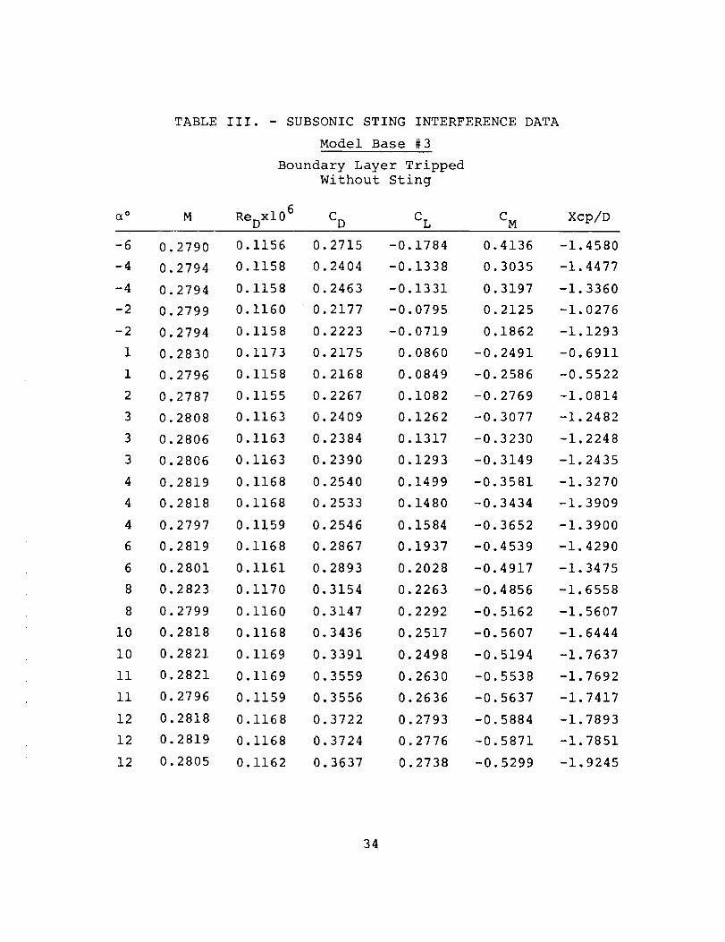
Model Base #3
Boundary Layer Tripped
Without Sting
6
ReDXl 0 C D C L C M
DATA
Xcp/D
-6
-4
-4
-2
-2
1
1
2
3
3
3
4
4
4
6
6
8
8
i0
i0
ii
ll
12
12
12
.2790
.2794
.2794
.2799
.2794
.2830
.2796
.2787
.2808
.2806
.2806
.2819
.2818
.2797
.2819
.2801
.2823
.2799
.2818
.2821
.2821
.2796
.2818
.2819
.2805
0.1156
0.1158
0.1158
0.1160
0.1158
0.1173
0.1158
0.1155
0.1163
0.1163
0.1163
0.1168
0.1168
0.1159
0.1168
0.1161
0.1170
0.1160
0.1168
0.1169
0.1169
0.1159
0.1168
0.1168
0.1162
0.2715 -0.1784 0.4136
0.2404 -0.1338 0.3035
0.2463 -0.1331 0.3197
0.2177 -0.0795 0.2125
0.2223 -0.0719 0.1862
0.2175 0.0860 -0.2491
0.2168 0.0849 -0.2586
0.2267 0.1082 -0.2769
0.2409 0.1262 -0.3077
0.2384 0.1317 -0.3230
0.2390 0.1293 -0.3149
0.2540 0.1499 -0.3581
0.2533 0.1480 -0.3434
0.2546 0.1584 -0.3652
0.2867 0.1937 -0.4539
0.2893 0.2028 -0.4917
0.3154 0.2263 -0.4856
0.3147 0.2292 -0.5162
0.3436 0.2517 -0.5607
0.3391 0.2498 -0.5194
0.3559 0.2630 -0.5538
0.3556 0.2636 -0.5637
0.3722 0.2793 -0.5884
0.3724 0.2776 -0.5871
0.3637 0.2738 -0.5299
-1.4580
-1.4477
-1.3360
-1.0276
-1.1293
-0.6911
-0.5522
-1.0814
-1.2482
-1.2248
-1.2435
-1.3270
-1.3909
-1.3900
-1.4290
-1.3475
-1.6558
-1.5607
-1.6444
-1.7637
-1.7692
-1.7417
-1.7893
-1.7851
-1.9245
34
I'-'I--'I--" I'-'I--' I I I I I I Il',o0 0 0 0 O0 O0 OO GO 0'_ 0"_ 0'_ 0", _ _ _ ,_ _ OJ I,o _ _ 0 I--' i',Ol",o_ _ ,I_ _ o
_n
0 0 0 0 0 0 0 0 0 0 0 0 0 0 0 0 0 0 0 0 0 0 0 0 0 0 0 0 0 0
...... ...... , .... ......
_ o _ _ _ _ _ _ _ _ _ _ _ _ _ _ o o o o o o o o o o o o o
o o o o o o o o o o o o o o o o o o o o o o o o o o o o o o• • • • • • • • • • • • • • • • • • • • • • • • • e • • • •
I--' _ I-_ h-J I--' _ I-_ I--' I--' _ t-_ _ I-J _ I-J I-_ _ _ I--' _ I-_ I--' I---' I--' I-_ t--' I-_ I--' I-J0"_ _ 01 _ 0"1 brl Lrl O_ Lrl Lrl _ O_ 01 01 ,1_ O'l 01 0"1 L.n 0"1 0"I _rl 01 01 0"1 Lrl Lrl 01 Ln
_0 0 O0 0 IDO 0"_ IxJ 0 0 0"1 I._ .-..J 50 ,_ L_ _, GO ,DO _ -..J _ _ _ O_ ....I _ _ -_l _
0 0 0 0 0 0 0 0 0 0 0 0 0 0 0 0 0 0 0 0 0 0 0 0 0 0 0 0 0 0
0 0 0 0 O0 _.1 {_0 O0 O'l Lrl 01 _ _ I'0 I_ t,,J, IxJ I-_ 0 I-_ 0 _ '_P 0 0 0 I--' _ OJ_0 01 O_ O0 1',3 '_1 I--' 0 0 I--' _ kO "_1 _ _0 0"_ 0 O0 _ 0 I'-' _ _ 0 I-_ O0 0'I _ {3t
CO 0 O0 0 ,_ I--' _0 O0 01 O_ g:_ I--' _0 _ 0 _ 0 _l t,O O0 0 ,1_ 0 _ _ OD ,_0 _ _
I I I I I I I0 0 0 0 0 0 0 0 0 0 0 0 0 0 0 0 0 0 0 0 0 0 0 0 0 0 0 0 0 0
............. • • ............I_J l_J I_ I_ l_J _ I_ _ I_ _ IX_ l_J Ix_ _ _ l-_ I-_ _ k-_ 0 0 0 0 0 I-_ I-_ I-_ I-_
--I _ _X) _, _ _ _ _ b._ _ 0 0 0 _ _ _ O_ _ Lrl _ 40 I-_ _ OJ _J 01 _0 Cr_ _ "-.,I
I I I I I I I I I I I I I I I I I I I I I I I0 0 0 0 0 0 0 0 0 0 0 0 0 0 0 0 0 0 0 0 0 0 0 0 0 0 0 0 0 0
00 _ _ 01 _ _ -_I I-_ I_ l_J _ O_ _ _ O0 0 O_ l--'_ O0 _0 _ _ kid IXJ, _ _.l OJ 0kO 0% _ 0TM, I--' W J=_ Ln O0 O0 L_ ---I_. I_ _0 0 ,_ kO U'I _ --.I 01 g_. I--' 0 _1 GO 0 _0 ,,_kO kO I..,00 L_ 0"I _D 0 40 _ _0 01 g:_ 0 k-_ -_I I_ _4 _ 0 O0 0% _0 -,,40-I _ J:x 0 I._ I_
{D
o
f_U
C_
C_
(I
0
Os
I_._
{I)
I-4HH
I
U_
=--I
::_ H
L_

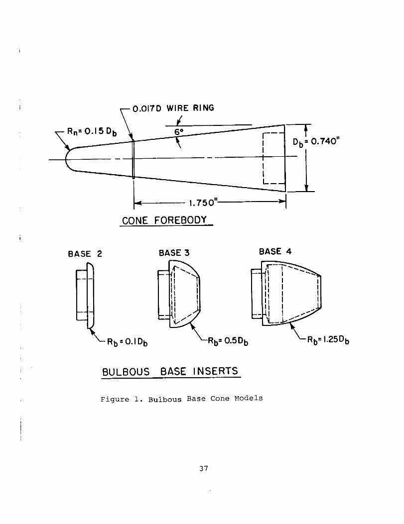
Rn = 0.1 5 D b
0.0i7 D WIRE
/6o
RING
1.750"
CONE FOREBODY
IIL.
Db=0.740"
BASE
mm
2
_-Rb=O.ID b
BASE 5
Rb= 0.5 Db
BASE 4
1.25D b
BULBOUS BASE INSERTS
Figure i. Bulbous Base Cone Models
37
LUCO
TUNNEL
NOTE: MODEL AND STING ARE NOT
IN PHYSICAL CONTACT WITH
EACH OTHER.
FMODEL ROTATIONCENTER
II
• t88
MMY STING
_ 1.00"------_
( NON- METALLIC)
L-MODEL BASE CAVITY
DUMMY STING
SUPPORT
TEST SECTION _ _ //_//WALL t_1111/, III IIII
Figure 2. Sting Interference Test Arrangement

oJkD
BASE 5 .20
.20
.20
M = 4.23
Re D_- 0.76 x 10⁵
NOTE_ FLAGGEDSYMBOLS DENOTEREPEAT POINTS
I-I0
Figure 3.
l I I I I I I I I- 8 -6 -4 - 2 0 2 4 6 8 I0
a (DEGREES)
Supersonic Drag Coefficient versus Angle of Attack (All Models)

.4 .4 .4 .4 BASE I M = 4.23
t RED"' 0.76 x 10 5
CL BASE 2
.3 .3 .3 .3
BASE 3
.2 .2 .2 .2 BASE 4
o
.I .I NOTE FLAGGED SYMBOLSDENOTE REPEAT POINTS
I I I I I I 1 I-6 -4 -2 2 4 6 8 I0 12
e (DEGREES)
-J o.I -.I -.I
-.2 -.2 -.2 -.2
Figure 4. Supersonic Lift Coefficient versus Angle of Attack (All Models)

.2 .2, .2 .2
! I ,o-4 -2
Figure 5.
BASE 4
BASE 3
M=4.25
Re D'- 0.76 x 10⁵
BASE 2
BASEl
I I6 8 I0
a (DEGREES)
J12
Supersonic Pitching Moment Coefficient versus Angle of Attack
(All Models)
l,o
BASEl
.4C L
Re D_" O. 12 x 10 6
0 UNTRIPPED
BOU NDARY LAYER
TRIPPED
.! NOTE" FLAGGED SYMBOLS
DENOTE REPEAT POINTS
I I I I I ! I I-8 -6 -4 -2 4 6 8 I0 12
-I0 -8 -6 2 4 6 8 I0
a (DEGREES)
1
12
Figure 6. Subsonic Lift Coefficient versus Angle of Attack (Base 1 Model)

.4O
/
.35
.30
:,_r, .20 M" 0.2 8
Re D_ O.12xlO 6
.15 m
.10 m
I-4 -2 0
0 UNTRIPPED
BOUNDARY LAYER TRIPPED
NOTEI FLAGGED SYMBOLS DENOTE
REPEAT POINTS
I I I I I I2 4 6 8 I0 12
a (DEGREES)
Figure 7. Subsonic Drag Coefficient versus Angle of Attack (Base 1 Model)
.6
0C_
-_2
-I.0
-8
I I-6 -4 -2
I I I I IBASE I
M=' 0.28
ReD= 0.12 x 10⁶
0 UNTRIPPED
n BOUNDARY LAYER TRIPPED
NOTE: FLAGGED SYMBOLS DENOTEREPEAT POINTS
I I I ]0 2 4 6 8 I0 12
e (DEGREES)
Figure 8. Subsonic Pitching Moment Coefficient versus Anale of Attack(Base 1 Model)

£n
.4
.3
-°3
-8
.I
C L
0
-.I
-.2
Figure
I I I , ' i I iM _" 0.28
BASE 2
RED.,,, O.12xiO 60 UNTRIPPED
_7 BOUNDARY LAYER TRIPPED
NOTE" FLAGGED SYMBOLS DENOTE
REPEAT POINTS
•
I ! !-6 -4 -2
Subsonic Lift
0 2 4 6 8 I0
a (DEGREES)
Coefficient versus Angle of Attack (Base 2 Model)
12
.45
CD
.40
O'%
[ J-I0 -8
.15
BASE 2
M_0.28
ReD_ O.12xlO 6
0 UNTRIPPED
BOUNDARY LAYER TRIPPED
1 I I 1 I I I I I-6 -4 -2 0 2 4 6 8 I0 12
(:z (DEGREES)
Figure i0. Subsonic Drag Coefficient versus Angle of Attack (Base 2 Model)
.6
.4 --
.2 --
0
CM
--° 2
--°4
-.8
-8
Figure ii.
I I I
0O
I I I I IBASE 2
M" 0.28
ReD_ O.12xlO 6
0 UNTRIPPED
D BOUNDARY LAYER TRIPPED
I I I I I I I I- 6 -4 - 2 0 2 4 6 8 I0
(:z (DEGREES)
Subsonic Pitching Moment Coefficient versus Angle of Attack
(Base 2 Model)
12
(X)
.4 -
.5 --
.2
CL
0
_ 2
-._
-I0
I I I I
0 28
-" 0.12 x 10⁶
M_0.28
Re D
0 UNTRIPPED
BOUNDARY LAYER TRIPPED l/
CONTINUOUS PLOT OF /LIFT VERSUS ANGLE /
OF ATTACK //
I I I I I I I I-8 -6 -4 - 2 0 2 4 6 8
a (DEGREES)I0 12
Figure 12. Subsonic Lift Coefficient versus Angle of Attack (Base 3 Model)
kD
I-8
co4°[- /.35
.15
.10
• 05
M= 0.28
ReD_ 0.12 x I0 6
0 UNTRIPPED
_7 BOUNDARY LAYER TRIPPED
I I I I I I I !-4 -2 0 2 4 6 8 I0 12
a (DEGREES)
Figure 13. Subsonic Drag Coefficient versus Angle of Attack (Base 3 Model)
u1c)
.8
.2
CM 0
-.2
-.4
-.6
-.8
-!.0-8
I I I I I I I I
BASE 3
I I I-6 -4 -2
M _- 0.28
RED'- O.12 x IO6O UNTRI PPEDn BOUNDARY LAYER TRIPPED
J I I I I0 2 4 6 8 I0 12
e (DEGREES)
Figure 14. Subsonic Pitching Moment Coefficient versus Angle of Attack

u1t-"
.4
.3
.2
.I
CL
0
-.I
-.2
I I i I
BASE 4
I I i i I
M" 0.28
Reo,,- 0.12 x 10⁶
0 UNTRIPPED IV BOUNDARY LAYER TRIPPED
_=.,-_-_'__='_ NOTE: FLAGGED SYMBOLS DENOTE
REPEAT POINTS
12
I I I I I ! I I I-8 -6 -4 -2 0 2 4 6 8 I0
a (DEGREES)
Figure 15. Subsonic Lift Coefficient versus Angle of Attack (Base 4 Model)

£nI,,3
.4
m
o I-IO -8
CD
.2
.I
Figure 16.
I I I IBASE 4
M-_O. 28
ReD_ 0.12x10⁶
I I ! I 1
0 UNTRIPPED
BOUNDARY LAYER TRIPPED
NOTE: FLAGGED SYMBOLS 'DENOTEREPEAT POINTS
I I I 1 I I I I-6 -4 -2 0 2 4 6 8 I0
e (DEGREES)
Subsonic Drag Coefficient versus Angle of Attack (Base 4 Model)
12

Ln(._
.6
.4
.2
0
C M
-.4
-.6
-.8
-I.0-I0
I I I I
BASE 4
m M_0.28
ReD -_ O.12xlO 6
0 UNTRIPPED
El BOUNDARY LAYER TRIPPED
1 1 1 I I
I I I I I I 1 I-8 -6 -4 -2 0 2 4 6 8
a (DEGREES)
I0 12
Figure 17. Subsonic Pitching Moment Coefficient versus Angle of Attack
(Base 4 Model)

L.n
1.0
0
-I.0
-2.0
Xcp
--6--
-5.0
-4.0
-5.0
-6.0-8
1
Figure 18.
\ I I I I I '
O
BASE 4
0 UNTRIPPED
C] BOUNDARY LAYER TRIPPED
M" 0.28
ReD_ 0.12 xlO 6
I I I I I I- 6 -4 -2 0 2 4 6 8 I0
a (DEGREES)
Subsonic' Center of Pressure Location versus Angle of Attack(Base 4 Model)
12

(.,rl£;'1
CI..
Figure 19.
I I I
BASE 3
M'" 0.28_ ReD'Z'-O. 12xI06
BOUNDARY LAYER TRIPPED
0 NO STING
/k WITH STING
NOTE: FLAGGED SYMBOLS DENOTE
REPEAT POINTS
I I I I I
I I I 1 I I I-4 -2 0 2 4 6 8 I0 12
a (DEGREES)
Effects of Sting Interference on the Lift Coefficient versus
Angle of Attack (Base 3 Model)
_m
.4O
CD
.35
,30
• 25
.15
.10
I I I I I-6 -4 -2 0 2 12
Figure 20.
M _- 0.28
Re D_- 0.12xl06
BOUNDARY LAYER TRIPPED
0 NO STING
/_ WITH STING
I I I I4 6 8 I0
a ( DEGREES )
Effects of Sting Interference on the Drag Coefficient versus
Angle of Attack (Base 3 Model)
I14

C3b_!I-"
k(DLNI'0
CL
.5
.4
.3
.2
1 I IBAS E 3
BOUNDARY LAYER TRIPPED
0 REFERENCE I ; ReD'z- 1.26x10⁶
A WITH STING L PRESENT DATA
0 WITHOUT STING_ ReD',,O.12xlO 6
I I I 1 I
u., .I-.I
0
-.I
-.2-8 -6
Figure 21.
I I I I I I-4 -2 0 2 4 6 8 I0 12
(2 (DEGREES)
Subsonic Lift Coefficient versus Angle of Attack (Base 3 Model)