Embed Size (px)
Citation preview

1
Cascade
Aqua-Aire®
Premier Bathing Systems
Parts Breakdown & Assemblies Side Entry – Side Entry High Seat – End-opening – Swivel Lift Tub
Premier Standard Premier Elite 360020-1P 360020-1EP
Cabinet Styles: Standard and Elite Premiers
360748P Revision “G” 12/17/18
Penner Patient Care 101 Grant Street Aurora. NE 68818
For Service Please Call:
1-800-732-0717 or 1-866-736-6377
Visit Our Web Site: h t t p : / / p e n n e r b a t h i n g s p a s . c o m /
Table of Contents Rada 320 Mixing Valve Service Component Breakdown & Removal ..................................................................... 4
Mixing Valve Adjustment ........................................................................................................................................ 5
Mixing Valve Adjustment Rada 222 ........................................................................................................................ 6
Checking for the correct dilution of disinfection .................................................................................................... 7
Electrical Box Standard and Elite Premier .............................................................................................................. 8
Timer Adjustments Explanation ............................................................................................................................. 8
TV, Mounting, and Glass (Standard and Elite) ........................................................................................................ 8
Inside Tub Components Drain and Temperature Probe ......................................................................................... 9
Water Doors with lock ............................................................................................................................................ 9
Side Opening Water Door Internal Parts .............................................................................................................. 10
Water Door Internal & Exterior ............................................................................................................................ 10
Water Door Handle (Side and End Opening) ........................................................................................................ 10
End Opening Door Internal Parts .......................................................................................................................... 11
End Opening Door Parts ....................................................................................................................................... 11
Jets - Parts ............................................................................................................................................................. 12
Plumbing Drain and Overflow............................................................................................................................... 13
Temperature Probe .............................................................................................................................................. 13
Drain and Overflow Complete Assembly .............................................................................................................. 14
Blower and Water Trap Assembly ........................................................................................................................ 14
Swivel Lift Actuator Limit Switch Parts ................................................................................................................. 15
Swivel Lift Actuator Breakdown............................................................................................................................ 15
Swivel Lift Chair Components ............................................................................................................................... 16
Swivel Lift Scale ..................................................................................................................................................... 16
Swivel Lift Electrical Box ....................................................................................................................................... 17
Swivel lift tub Calibration Procedure ..................................................................................................................... 18
Controls - Standard Premier ................................................................................................................................. 19
Bottle Tray and Check Valves................................................................................................................................ 20
Shower (by-pass) Hose Connection Standard & Elite Premiers ........................................................................... 20
Solenoids and Identification - Standard Premier .................................................................................................. 21
Water Supply Connection Points & Inlet Screens - Standard Premier ................................................................. 21
Plumbing - Standard Premier ............................................................................................................................... 22
Vacuum Breakers - Elite Premier .......................................................................................................................... 23
Air System Assembly - Standard and Elite Premier .............................................................................................. 23
Controls Deck - Elite PremierLeft Side Access Views - Elite Premier (Right Hand) ............................................... 24
Right Side Lower Access View - Elite Premier (Right Hand) ................................................................................. 25
Hoses - Elite Premier ............................................................................................................................................. 26
Solenoid Identification - Elite Premier .................................................................................................................. 26
Control Panel Elite Premier View From Behind .................................................................................................... 27
Inside the Reservoir .............................................................................................................................................. 27
Reservoir Gate Valve and Blower Location Elite Premier ..................................................................................... 28
Installation Kit includes the following: ................................................................................................................. 29
Tub Access Doors .................................................................................................................................................. 29
Cabinet Access Doors - Elite Premier .................................................................................................................... 29
Cabinet Access Doors - Standard Premier ............................................................................................................ 30
NOTE: (TV warranty is processed through the manufacturer of the TV) NOTE: Keep
your invoice or proof of purchase of the premier and the TV. This is your record of the TV
model, serial number, and the date of purchase. Telephone numbers of warranty contacts
are in the TV operating manual.
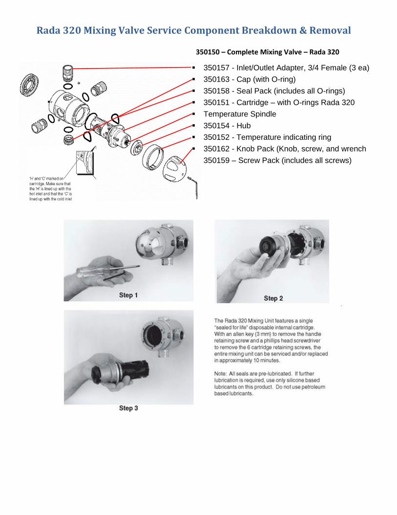
Rada 320 Mixing Valve Service Component Breakdown & Removal
350157 - Inlet/Outlet Adapter, 3/4 Female (3 ea)
350163 - Cap (with O-ring)
350158 - Seal Pack (includes all O-rings)
350151 - Cartridge – with O-rings Rada 320
Temperature Spindle
350154 - Hub
350152 - Temperature indicating ring
350162 - Knob Pack (Knob, screw, and wrench
350159 – Screw Pack (includes all screws)
350150 – Complete Mixing Valve – Rada 320
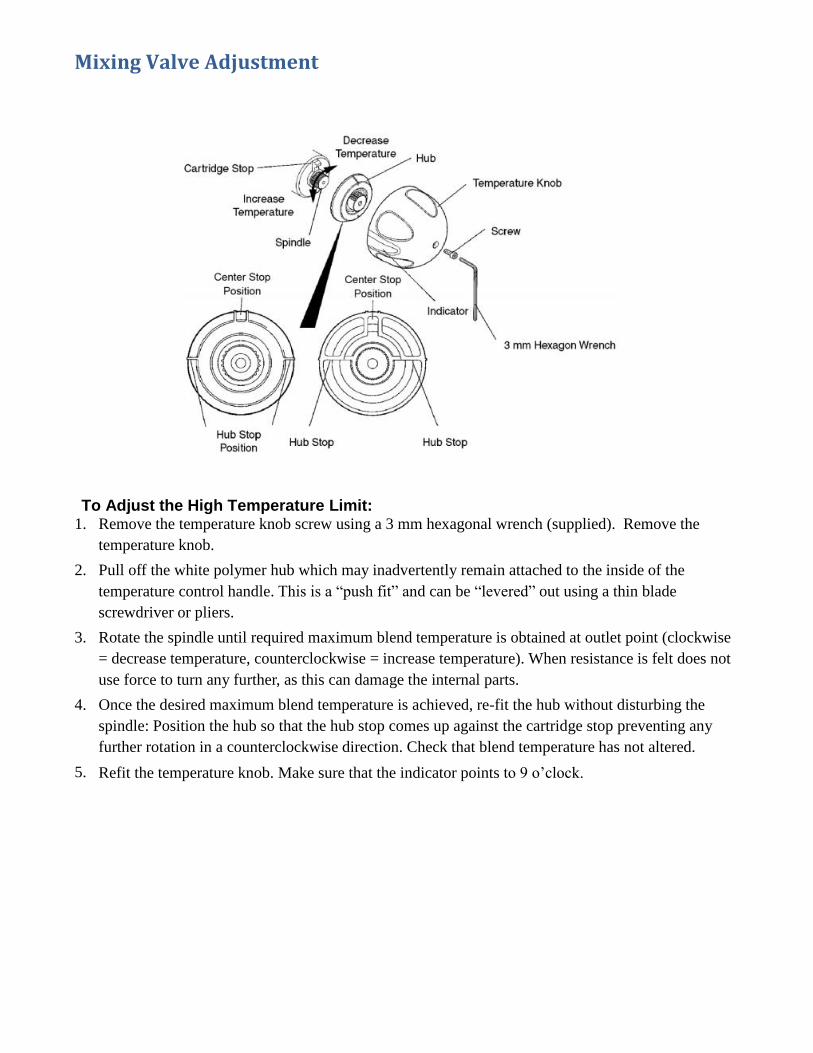
Mixing Valve Adjustment
To Adjust the High Temperature Limit: 1. Remove the temperature knob screw using a 3 mm hexagonal wrench (supplied). Remove the
temperature knob.
2. Pull off the white polymer hub which may inadvertently remain attached to the inside of the
temperature control handle. This is a “push fit” and can be “levered” out using a thin blade
screwdriver or pliers.
3. Rotate the spindle until required maximum blend temperature is obtained at outlet point (clockwise
= decrease temperature, counterclockwise = increase temperature). When resistance is felt does not
use force to turn any further, as this can damage the internal parts.
4. Once the desired maximum blend temperature is achieved, re-fit the hub without disturbing the
spindle: Position the hub so that the hub stop comes up against the cartridge stop preventing any
further rotation in a counterclockwise direction. Check that blend temperature has not altered.
5. Refit the temperature knob. Make sure that the indicator points to 9 o’clock.
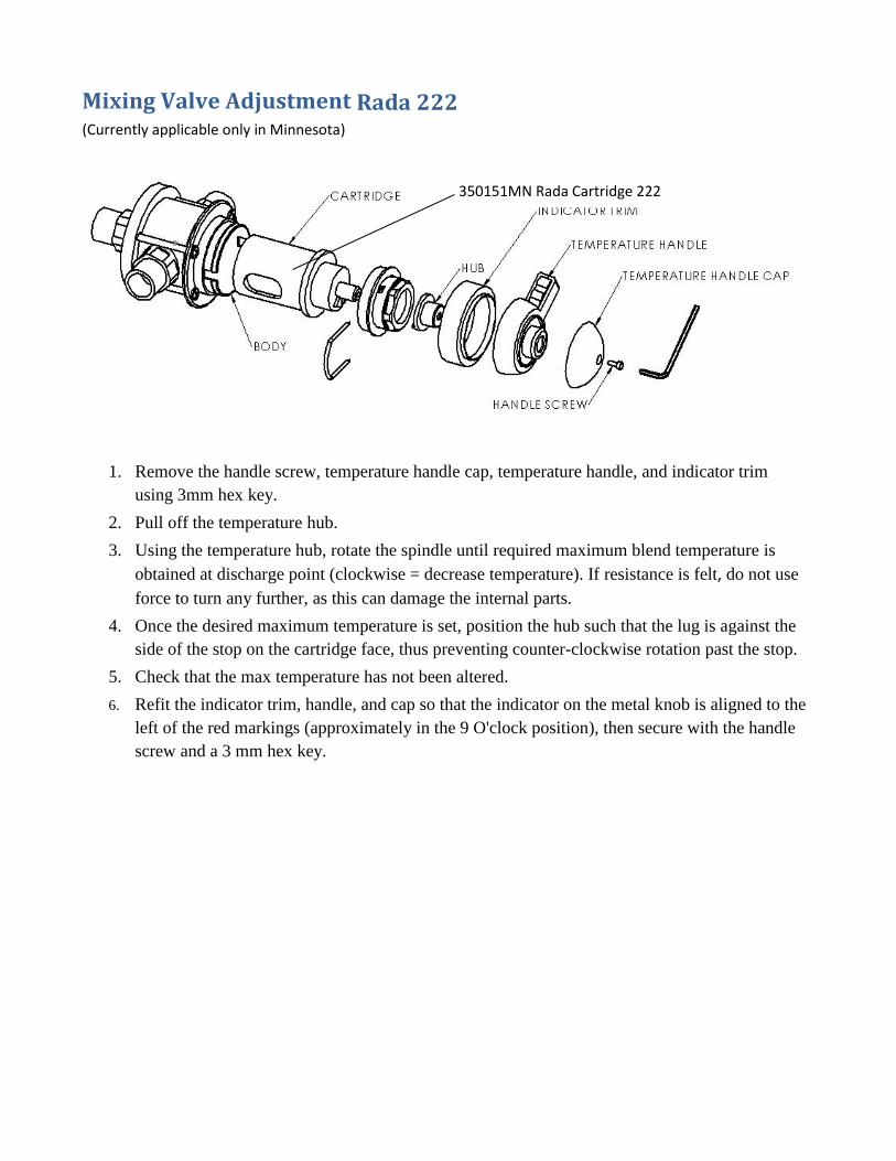
Mixing Valve Adjustment Rada 222 (Currently applicable only in Minnesota)
1. Remove the handle screw, temperature handle cap, temperature handle, and indicator trim
using 3mm hex key.
2. Pull off the temperature hub.
3. Using the temperature hub, rotate the spindle until required maximum blend temperature is
obtained at discharge point (clockwise = decrease temperature). If resistance is felt, do not use
force to turn any further, as this can damage the internal parts.
4. Once the desired maximum temperature is set, position the hub such that the lug is against the
side of the stop on the cartridge face, thus preventing counter-clockwise rotation past the stop.
5. Check that the max temperature has not been altered.
6. Refit the indicator trim, handle, and cap so that the indicator on the metal knob is aligned to the
left of the red markings (approximately in the 9 O'clock position), then secure with the handle
screw and a 3 mm hex key.
350151MN Rada Cartridge 222
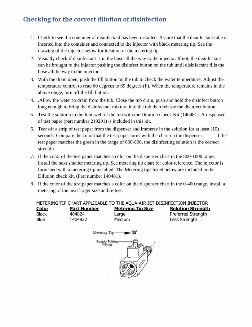
Checking for the correct dilution of disinfection
1. Check to see if a container of disinfectant has been installed. Assure that the disinfectant tube is
inserted into the container and connected to the injector with black metering tip. See the
drawing of the injector below for location of the metering tip.
2. Visually check if disinfectant is in the hose all the way to the injector. If not, the disinfectant
can be brought to the injector pushing the disinfect button on the tub until disinfectant fills the
hose all the way to the injector.
3. With the drain open, push the fill button on the tub to check the water temperature. Adjust the
temperature control to read 60 degrees to 65 degrees (F). When the temperature remains in the
above range, turn off the fill button.
4. .Allow the water to drain from the tub. Close the tub drain, push and hold the disinfect button
long enough to bring the disinfectant mixture into the tub then release the disinfect button.
5. Test the solution in the foot-well of the tub with the Dilution Check Kit (140481). A dispenser
of test paper (part number 219201) is included in this kit.
6. Tear off a strip of test paper from the dispenser and immerse in the solution for at least (10)
seconds. Compare the color that the test paper turns with the chart on the dispenser. If the
test paper matches the green in the range of 600-800, the disinfecting solution is the correct
strength.
7. If the color of the test paper matches a color on the dispenser chart in the 800-1000 range,
install the next smaller metering tip. See metering tip chart for color reference. The injector is
furnished with a metering tip installed. The Metering tips listed below are included in the
Dilution check kit, (Part number 140481).
8. If the color of the test paper matches a color on the dispenser chart in the 0-400 range, install a
metering of the next larger size and re-test.
METERING TIP CHART APPLICABLE TO THE AQUA-AIR JET DISINFECTION INJECTOR
Color Part Number Metering Tip Size Solution Strength Black 404824 Large Preferred Strength Blue 1404822 Medium Less Strength
8
360704 - (Standard) - 360704EP (Elite) TV HDTV/DVD
360705 - (Standard and Elite) TV Articulating Mount (not shown)
360865 - (Standard) Door Glass
361865 - (Elite) Door Glass
360522P - Outlet Spout – Premier
360305P - Reservoir Outlet Fitting - Premier
350220 - Dispenser Spout - Oil & Soap
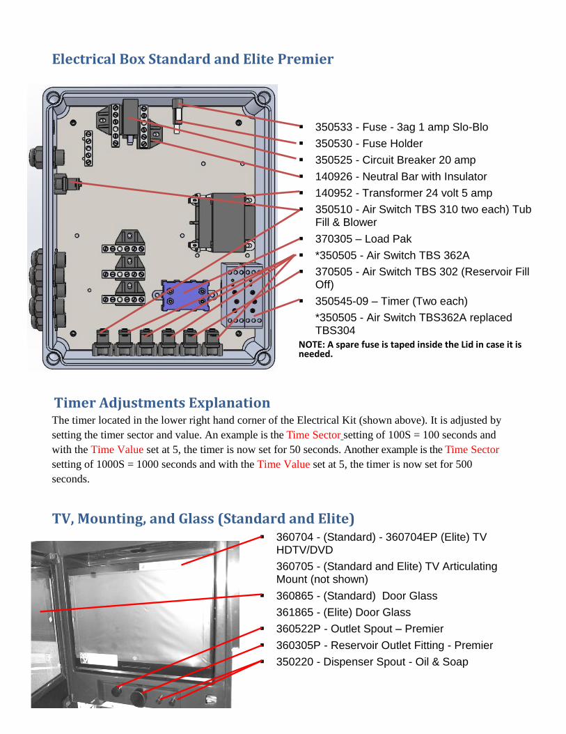
Electrical Box Standard and Elite Premier
Timer Adjustments Explanation The timer located in the lower right hand corner of the Electrical Kit (shown above). It is adjusted by
setting the timer sector and value. An example is the Time Sector setting of 100S = 100 seconds and
with the Time Value set at 5, the timer is now set for 50 seconds. Another example is the Time Sector
setting of 1000S = 1000 seconds and with the Time Value set at 5, the timer is now set for 500
seconds.
TV, Mounting, and Glass (Standard and Elite)
350533 - Fuse - 3ag 1 amp Slo-Blo
350530 - Fuse Holder
350525 - Circuit Breaker 20 amp
140926 - Neutral Bar with Insulator
140952 - Transformer 24 volt 5 amp
350510 - Air Switch TBS 310 two each) Tub Fill & Blower
370305 – Load Pak
*350505 - Air Switch TBS 362A
370505 - Air Switch TBS 302 (Reservoir Fill Off)
350545-09 – Timer (Two each)
*350505 - Air Switch TBS362A replaced TBS304
NOTE: A spare fuse is taped inside the Lid in case it is needed.
9
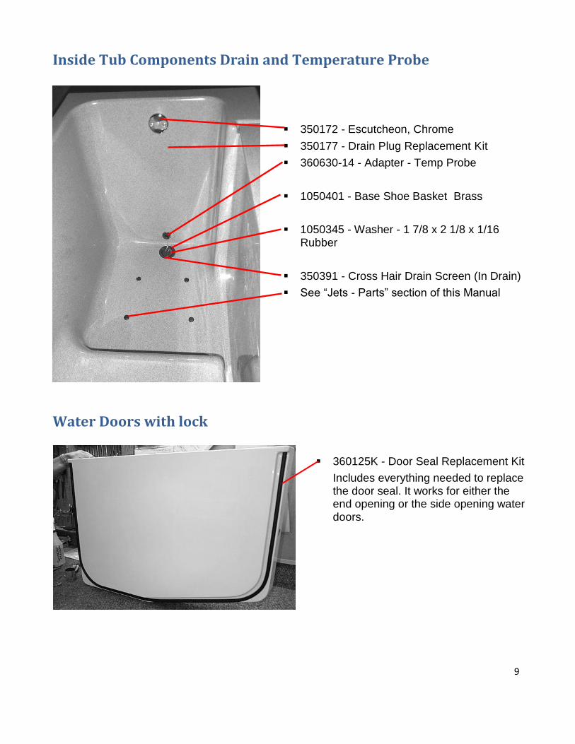
Inside Tub Components Drain and Temperature Probe
Water Doors with lock
360125K - Door Seal Replacement Kit
Includes everything needed to replace the door seal. It works for either the end opening or the side opening water doors.
350172 - Escutcheon, Chrome
350177 - Drain Plug Replacement Kit
360630-14 - Adapter - Temp Probe
1050401 - Base Shoe Basket Brass
1050345 - Washer - 1 7/8 x 2 1/8 x 1/16 Rubber
350391 - Cross Hair Drain Screen (In Drain)
See “Jets - Parts” section of this Manual
10
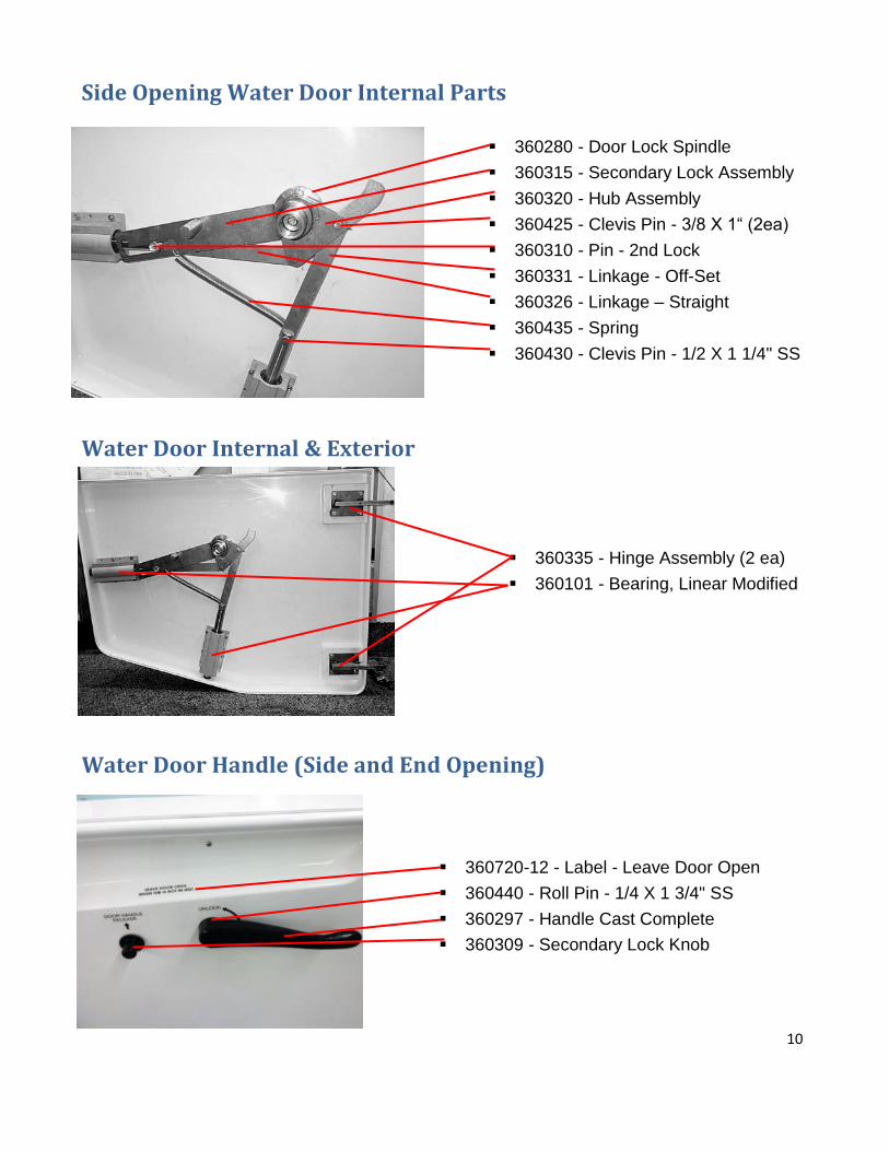
Side Opening Water Door Internal Parts
Water Door Internal & Exterior
Water Door Handle (Side and End Opening)
360335 - Hinge Assembly (2 ea)
360101 - Bearing, Linear Modified
360280 - Door Lock Spindle
360315 - Secondary Lock Assembly
360320 - Hub Assembly
360425 - Clevis Pin - 3/8 X 1“ (2ea)
360310 - Pin - 2nd Lock
360331 - Linkage - Off-Set
360326 - Linkage – Straight
360435 - Spring
360430 - Clevis Pin - 1/2 X 1 1/4" SS
360720-12 - Label - Leave Door Open
360440 - Roll Pin - 1/4 X 1 3/4" SS
360297 - Handle Cast Complete
360309 - Secondary Lock Knob
11
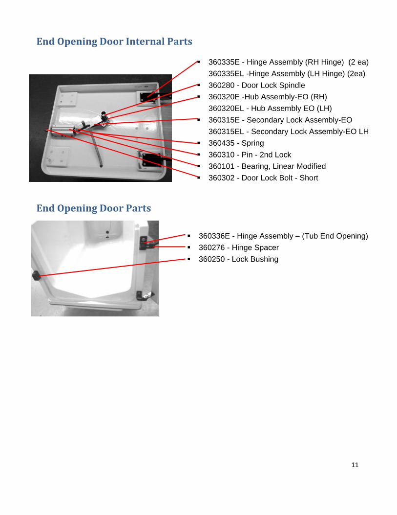
End Opening Door Internal Parts
End Opening Door Parts
360336E - Hinge Assembly – (Tub End Opening)
360276 - Hinge Spacer
360250 - Lock Bushing
360335E - Hinge Assembly (RH Hinge) (2 ea)
360335EL -Hinge Assembly (LH Hinge) (2ea)
360280 - Door Lock Spindle
360320E -Hub Assembly-EO (RH)
360320EL - Hub Assembly EO (LH)
360315E - Secondary Lock Assembly-EO
360315EL - Secondary Lock Assembly-EO LH
360435 - Spring
360310 - Pin - 2nd Lock
360101 - Bearing, Linear Modified
360302 - Door Lock Bolt - Short
12
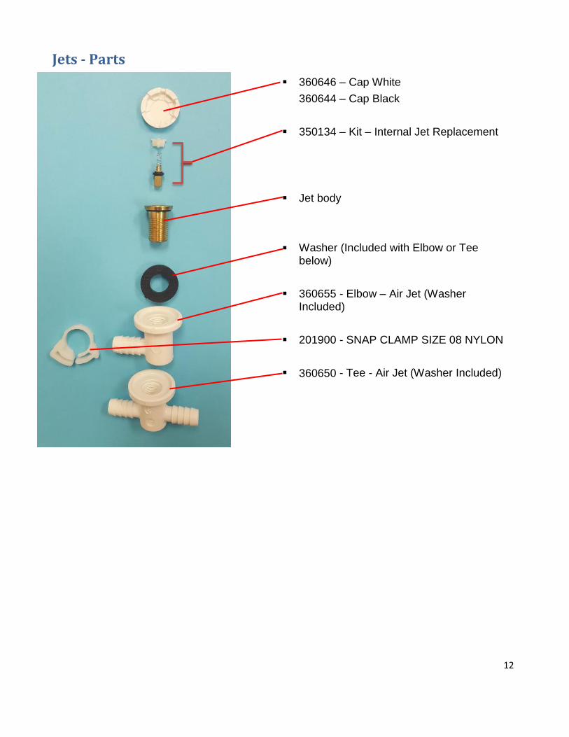
Jets - Parts
360646 – Cap White
360644 – Cap Black
350134 – Kit – Internal Jet Replacement
Jet body
Washer (Included with Elbow or Tee below)
360655 - Elbow – Air Jet (Washer Included)
201900 - SNAP CLAMP SIZE 08 NYLON
360650 - Tee - Air Jet (Washer Included)
13
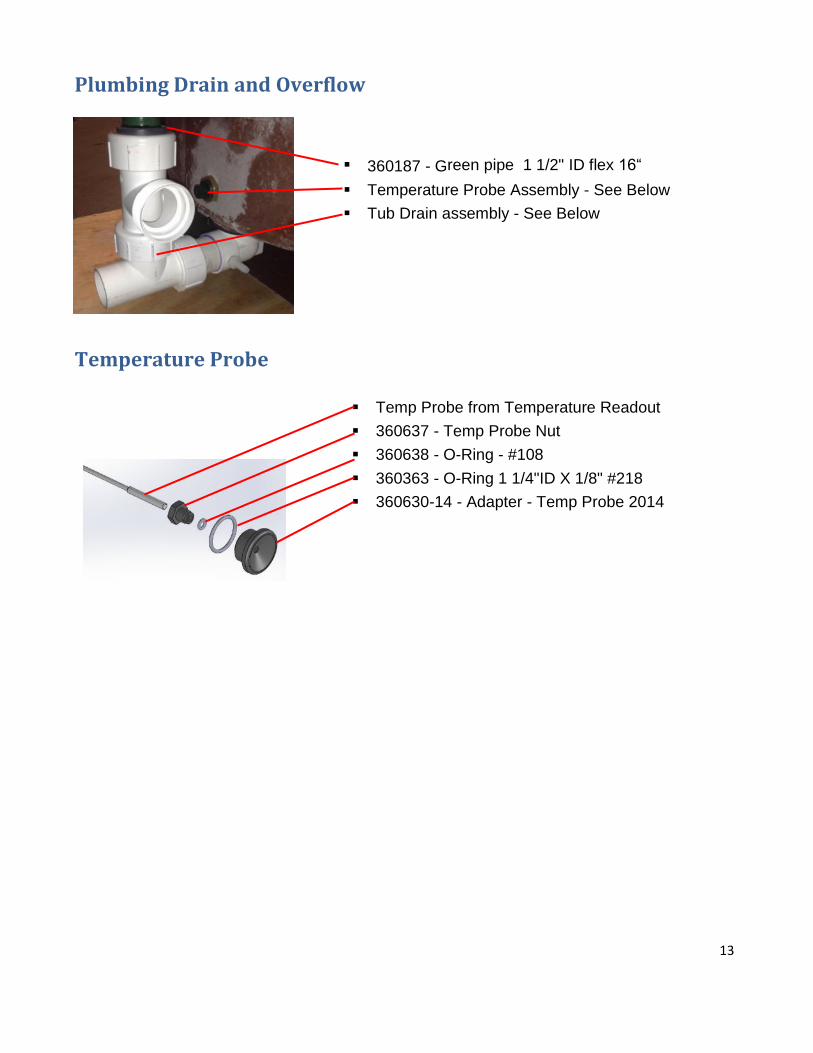
Plumbing Drain and Overflow
Temperature Probe
Temp Probe from Temperature Readout
360637 - Temp Probe Nut
360638 - O-Ring - #108
360363 - O-Ring 1 1/4"ID X 1/8" #218
360630-14 - Adapter - Temp Probe 2014
360187 - Green pipe 1 1/2" ID flex 16“
Temperature Probe Assembly - See Below
Tub Drain assembly - See Below
14
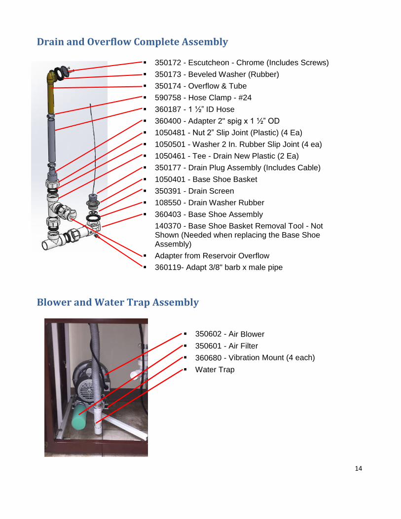
Drain and Overflow Complete Assembly
Blower and Water Trap Assembly
350602 - Air Blower
350601 - Air Filter
360680 - Vibration Mount (4 each)
Water Trap
350172 - Escutcheon - Chrome (Includes Screws)
350173 - Beveled Washer (Rubber)
350174 - Overflow & Tube
590758 - Hose Clamp - #24
360187 - 1 ½” ID Hose
360400 - Adapter 2" spig x 1 ½” OD
1050481 - Nut 2” Slip Joint (Plastic) (4 Ea)
1050501 - Washer 2 In. Rubber Slip Joint (4 ea)
1050461 - Tee - Drain New Plastic (2 Ea)
350177 - Drain Plug Assembly (Includes Cable)
1050401 - Base Shoe Basket
350391 - Drain Screen
108550 - Drain Washer Rubber
360403 - Base Shoe Assembly
140370 - Base Shoe Basket Removal Tool - Not Shown (Needed when replacing the Base Shoe Assembly)
Adapter from Reservoir Overflow
360119- Adapt 3/8" barb x male pipe
15
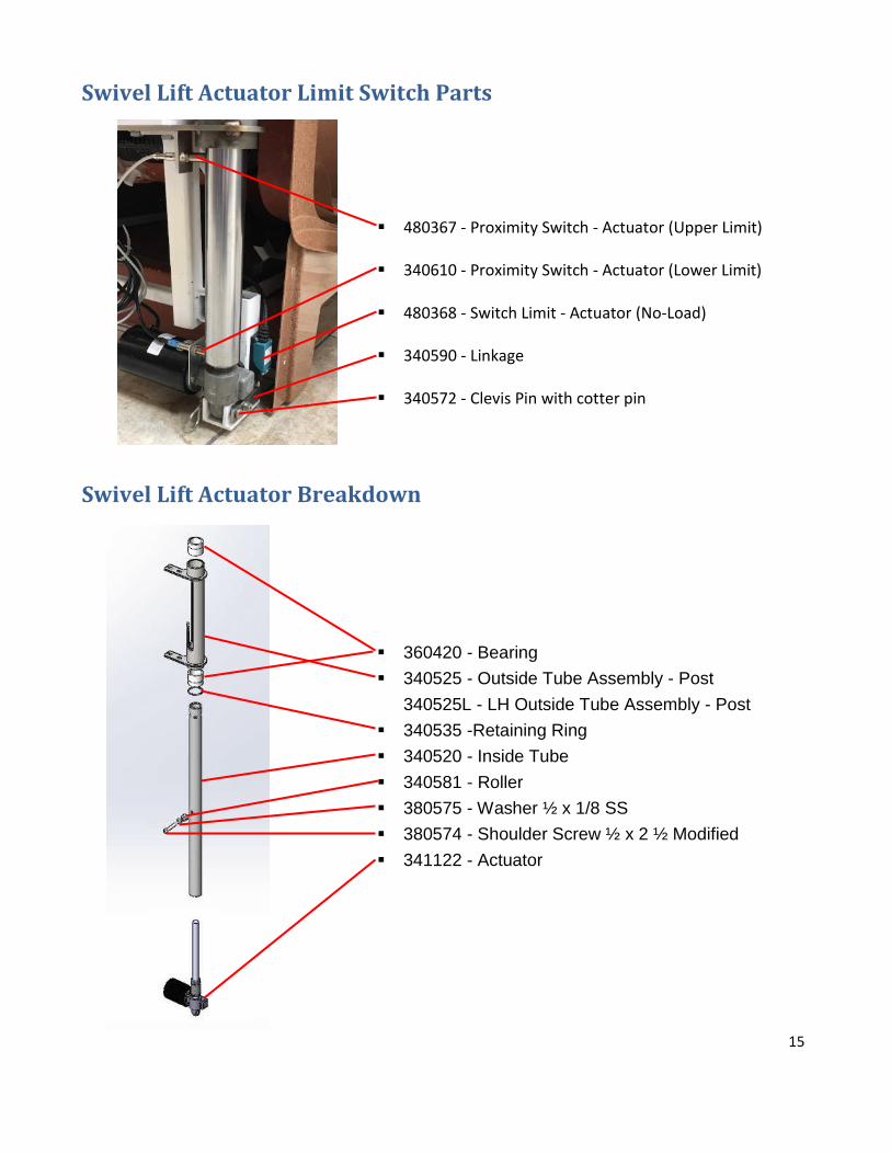
Swivel Lift Actuator Limit Switch Parts
Swivel Lift Actuator Breakdown
360420 - Bearing
340525 - Outside Tube Assembly - Post
340525L - LH Outside Tube Assembly - Post
340535 -Retaining Ring
340520 - Inside Tube
340581 - Roller
380575 - Washer ½ x 1/8 SS
380574 - Shoulder Screw ½ x 2 ½ Modified
341122 - Actuator
480367 - Proximity Switch - Actuator (Upper Limit)
340610 - Proximity Switch - Actuator (Lower Limit)
480368 - Switch Limit - Actuator (No-Load)
340590 - Linkage
340572 - Clevis Pin with cotter pin
16
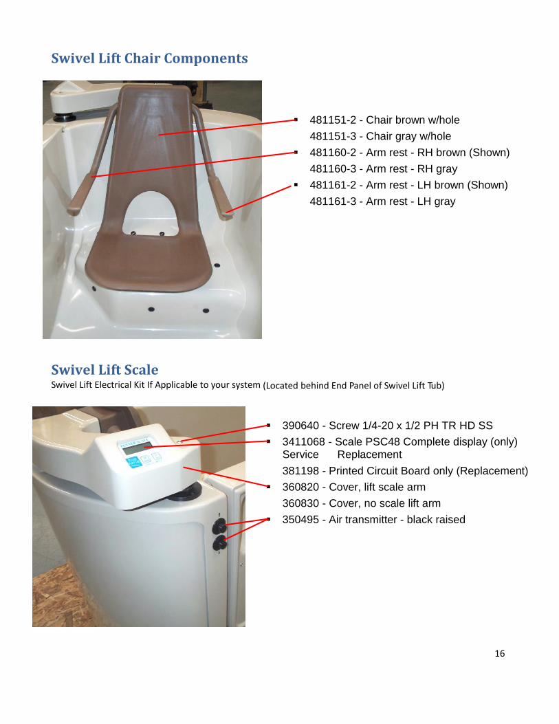
Swivel Lift Chair Components
Swivel Lift Scale Swivel Lift Electrical Kit If Applicable to your system (Located behind End Panel of Swivel Lift Tub)
481151-2 - Chair brown w/hole
481151-3 - Chair gray w/hole
481160-2 - Arm rest - RH brown (Shown)
481160-3 - Arm rest - RH gray
481161-2 - Arm rest - LH brown (Shown)
481161-3 - Arm rest - LH gray
390640 - Screw 1/4-20 x 1/2 PH TR HD SS
3411068 - Scale PSC48 Complete display (only) Service Replacement
381198 - Printed Circuit Board only (Replacement)
360820 - Cover, lift scale arm
360830 - Cover, no scale lift arm
350495 - Air transmitter - black raised
17
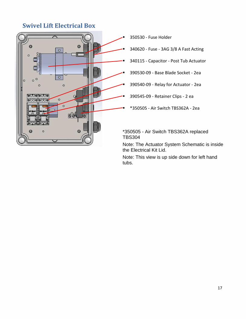
Swivel Lift Electrical Box
350530 - Fuse Holder
340620 - Fuse - 3AG 3/8 A Fast Acting
340115 - Capacitor - Post Tub Actuator
390530-09 - Base Blade Socket - 2ea
390540-09 - Relay for Actuator - 2ea
390545-09 - Retainer Clips - 2 ea
*350505 - Air Switch TBS362A - 2ea
*350505 - Air Switch TBS362A replaced TBS304
Note: The Actuator System Schematic is inside the Electrical Kit Lid.
Note: This view is up side down for left hand tubs.
18
Penner Manufacturing, Inc.
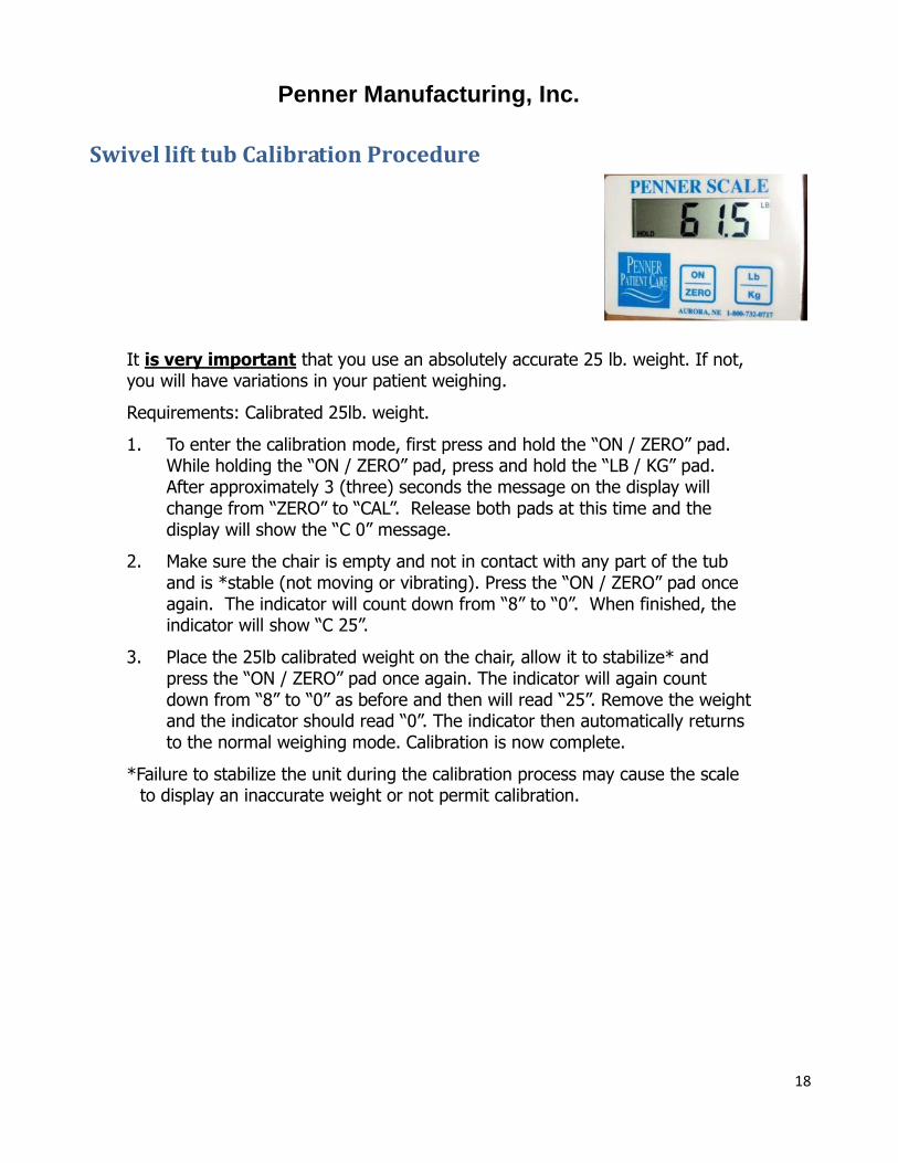
Swivel lift tub Calibration Procedure
It is very important that you use an absolutely accurate 25 lb. weight. If not, you will have variations in your patient weighing.
Requirements: Calibrated 25lb. weight.
1. To enter the calibration mode, first press and hold the “ON / ZERO” pad. While holding the “ON / ZERO” pad, press and hold the “LB / KG” pad. After approximately 3 (three) seconds the message on the display will change from “ZERO” to “CAL”. Release both pads at this time and the display will show the “C 0” message.
2. Make sure the chair is empty and not in contact with any part of the tub and is *stable (not moving or vibrating). Press the “ON / ZERO” pad once again. The indicator will count down from “8” to “0”. When finished, the indicator will show “C 25”.
3. Place the 25lb calibrated weight on the chair, allow it to stabilize* and press the “ON / ZERO” pad once again. The indicator will again count down from “8” to “0” as before and then will read “25”. Remove the weight and the indicator should read “0”. The indicator then automatically returns to the normal weighing mode. Calibration is now complete.
*Failure to stabilize the unit during the calibration process may cause the scale to display an inaccurate weight or not permit calibration.

19
Controls - Standard Premier
350535M-SER - Thermometer Display (Fahrenheit / Celsius) (3 ea)
350495 - Air Transmitter (9 Each)
370325 - Reservoir Handle
350151 - Replacement Valve Cartridge
350151MN - Cartridge for Rada 222 (Minnesota only)
350200 - Dispenser Pump Complete (2 ea)
350201 - "O" Ring for Dispenser Pump
(Included in 350200)
350204 - Spring - Dispenser Pump
(Included in 350200)
350210 - Nut - Pump Mount (White) (Included in 350200)
350215 - Cap - Dispenser Pump
(Included in (350200)
140106CHT - Hand Shower
360551 - Adapter - Shower Sprayer
350190CH - Hose Shower 78" Chrome
(Not Shown)
360550 - Deck Mount-Hand Shower
360431 - Latch - Magnetic W/Plate
20
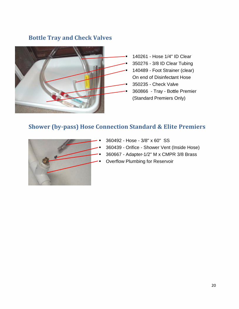
Bottle Tray and Check Valves
Shower (by-pass) Hose Connection Standard & Elite Premiers
360492 - Hose - 3/8" x 60" SS
360439 - Orifice - Shower Vent (Inside Hose)
360667 - Adapter-1/2" M x CMPR 3/8 Brass
Overflow Plumbing for Reservoir
140261 - Hose 1/4" ID Clear
350276 - 3/8 ID Clear Tubing
140489 - Foot Strainer (clear)
On end of Disinfectant Hose
350235 - Check Valve
360866 - Tray - Bottle Premier
(Standard Premiers Only)
21
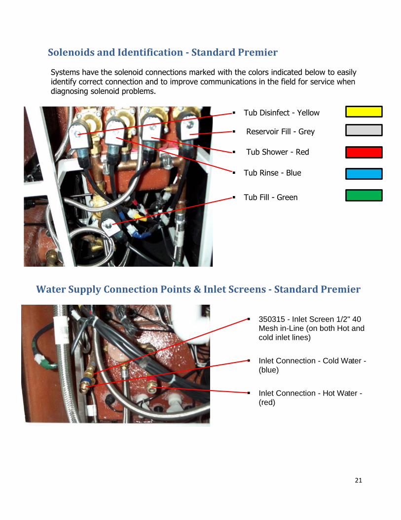
Solenoids and Identification - Standard Premier
Systems have the solenoid connections marked with the colors indicated below to easily identify correct connection and to improve communications in the field for service when diagnosing solenoid problems.
Water Supply Connection Points & Inlet Screens - Standard Premier
350315 - Inlet Screen 1/2" 40 Mesh in-Line (on both Hot and cold inlet lines)
Inlet Connection - Cold Water - (blue)
Inlet Connection - Hot Water - (red)
Tub Disinfect - Yellow
Reservoir Fill - Grey
Tub Shower - Red
Tub Rinse - Blue
Tub Fill - Green
22
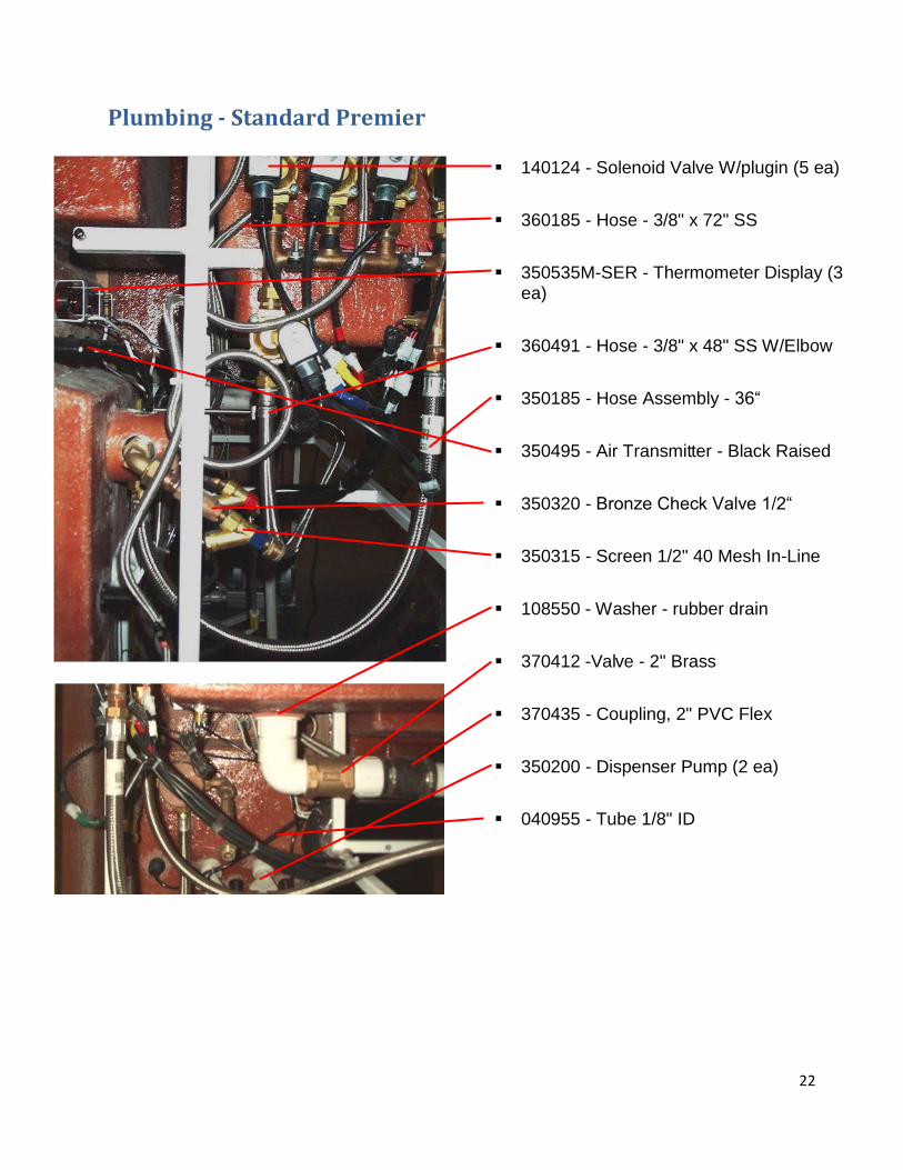
Plumbing - Standard Premier
140124 - Solenoid Valve W/plugin (5 ea)
360185 - Hose - 3/8" x 72" SS
350535M-SER - Thermometer Display (3 ea)
360491 - Hose - 3/8" x 48" SS W/Elbow
350185 - Hose Assembly - 36“
350495 - Air Transmitter - Black Raised
350320 - Bronze Check Valve 1/2“
350315 - Screen 1/2" 40 Mesh In-Line
108550 - Washer - rubber drain
370412 -Valve - 2" Brass
370435 - Coupling, 2" PVC Flex
350200 - Dispenser Pump (2 ea)
040955 - Tube 1/8" ID
23
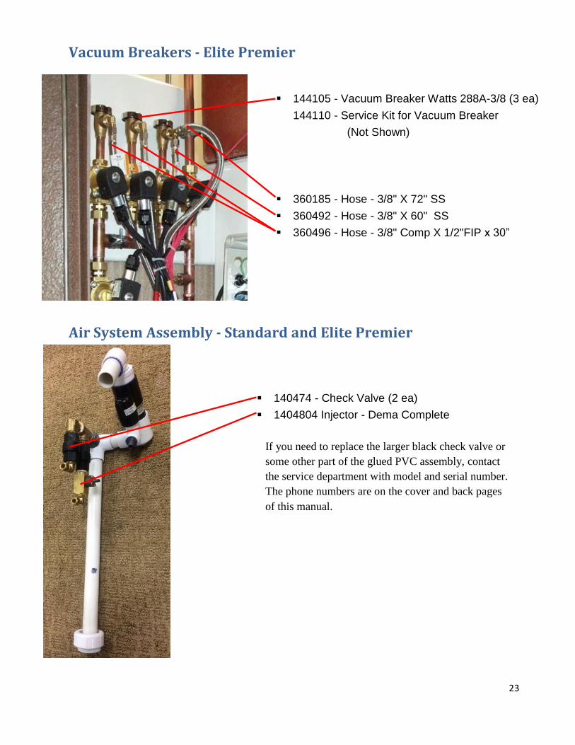
Vacuum Breakers - Elite Premier
Air System Assembly - Standard and Elite Premier
144105 - Vacuum Breaker Watts 288A-3/8 (3 ea)
144110 - Service Kit for Vacuum Breaker
(Not Shown)
360185 - Hose - 3/8" X 72" SS
360492 - Hose - 3/8" X 60" SS
360496 - Hose - 3/8" Comp X 1/2"FIP x 30”
140474 - Check Valve (2 ea)
1404804 Injector - Dema Complete
If you need to replace the larger black check valve or
some other part of the glued PVC assembly, contact
the service department with model and serial number.
The phone numbers are on the cover and back pages
of this manual.
24
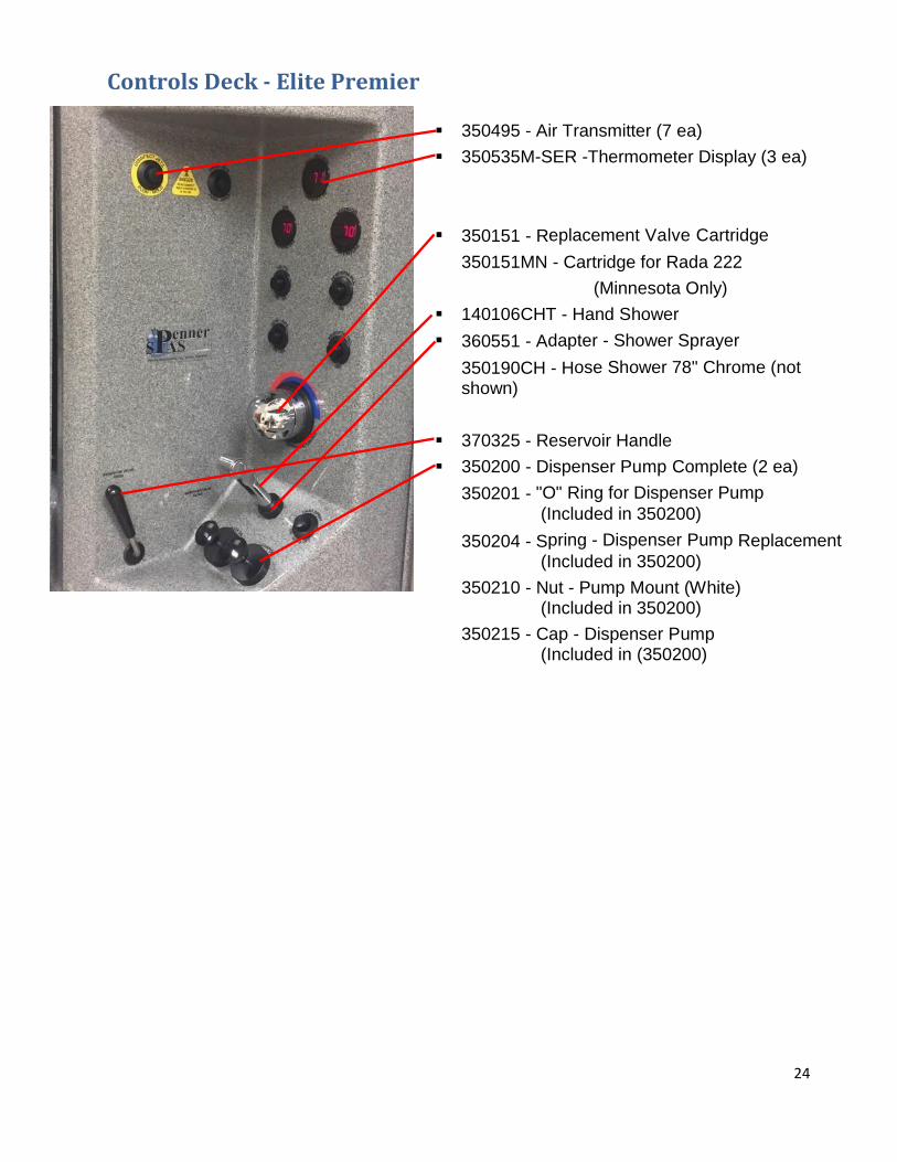
Controls Deck - Elite Premier
350495 - Air Transmitter (7 ea)
350535M-SER -Thermometer Display (3 ea)
350151 - Replacement Valve Cartridge
350151MN - Cartridge for Rada 222
(Minnesota Only)
140106CHT - Hand Shower
360551 - Adapter - Shower Sprayer
350190CH - Hose Shower 78" Chrome (not
shown)
370325 - Reservoir Handle
350200 - Dispenser Pump Complete (2 ea)
350201 - "O" Ring for Dispenser Pump
(Included in 350200)
350204 - Spring - Dispenser Pump Replacement
(Included in 350200)
350210 - Nut - Pump Mount (White) (Included in 350200)
350215 - Cap - Dispenser Pump (Included in (350200)
25
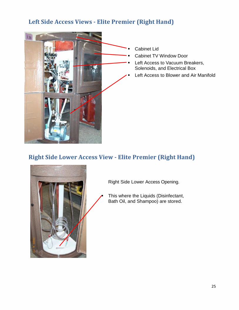
Left Side Access Views - Elite Premier (Right Hand)
Right Side Lower Access View - Elite Premier (Right Hand)
Right Side Lower Access Opening.
This where the Liquids (Disinfectant, Bath Oil, and Shampoo) are stored.
Cabinet Lid
Cabinet TV Window Door
Left Access to Vacuum Breakers, Solenoids, and Electrical Box
Left Access to Blower and Air Manifold
26
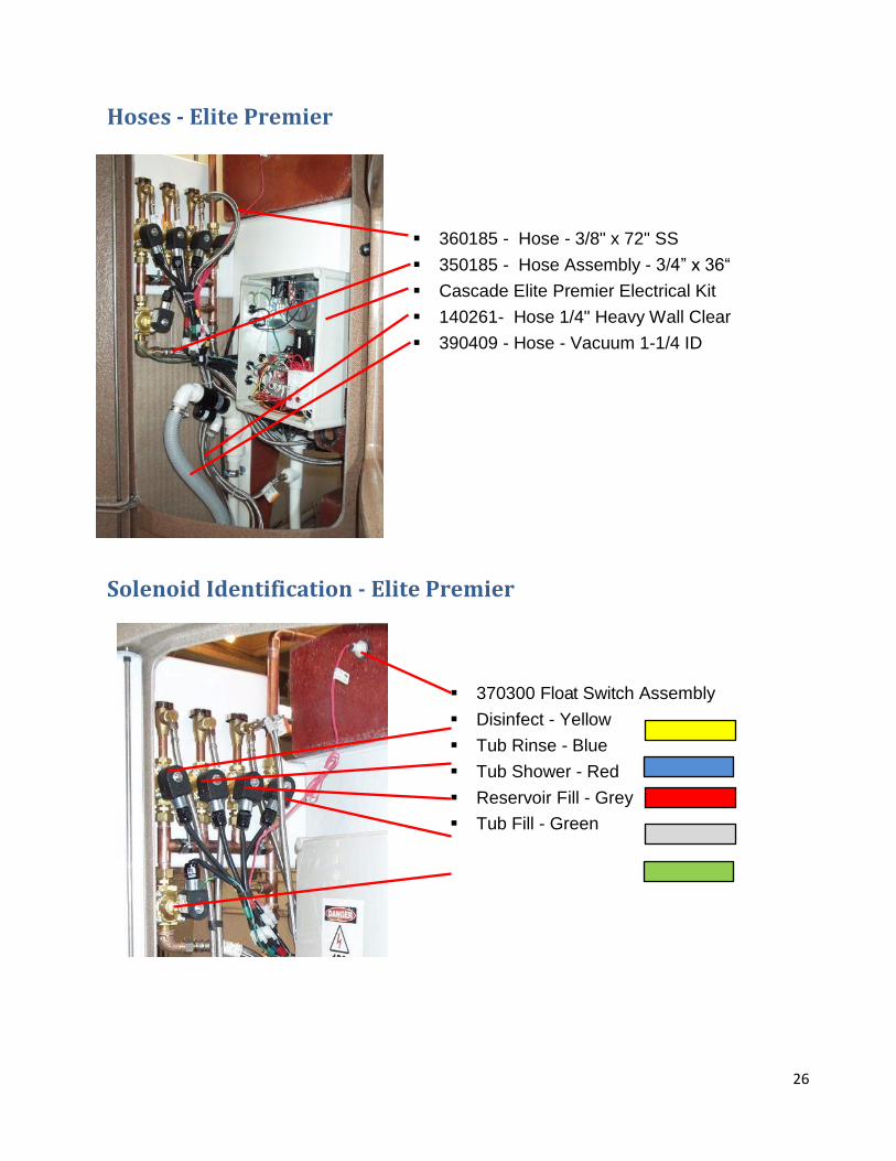
Hoses - Elite Premier
Solenoid Identification - Elite Premier
360185 - Hose - 3/8" x 72" SS
350185 - Hose Assembly - 3/4” x 36“
Cascade Elite Premier Electrical Kit
140261- Hose 1/4" Heavy Wall Clear
390409 - Hose - Vacuum 1-1/4 ID
370300 Float Switch Assembly
Disinfect - Yellow
Tub Rinse - Blue
Tub Shower - Red
Reservoir Fill - Grey
Tub Fill - Green
27
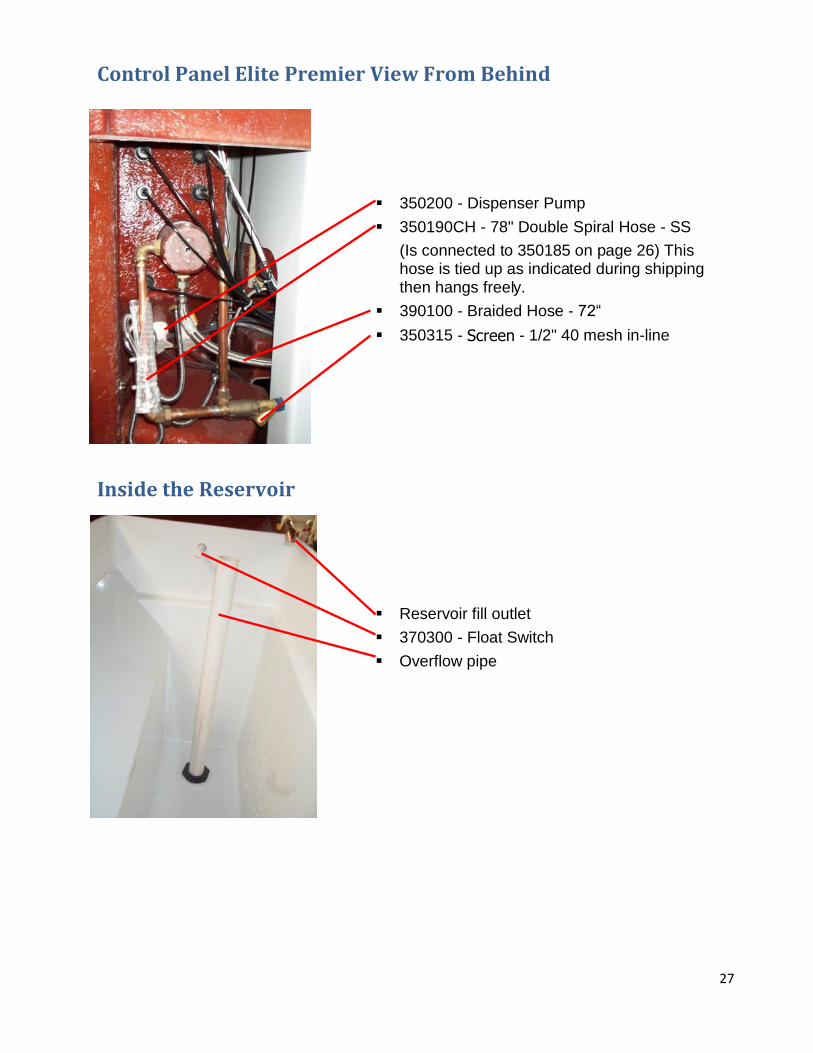
Control Panel Elite Premier View From Behind
Inside the Reservoir
Reservoir fill outlet
370300 - Float Switch
Overflow pipe
350200 - Dispenser Pump
350190CH - 78" Double Spiral Hose - SS
(Is connected to 350185 on page 26) This hose is tied up as indicated during shipping then hangs freely.
390100 - Braided Hose - 72“
350315 - Screen - 1/2" 40 mesh in-line
28
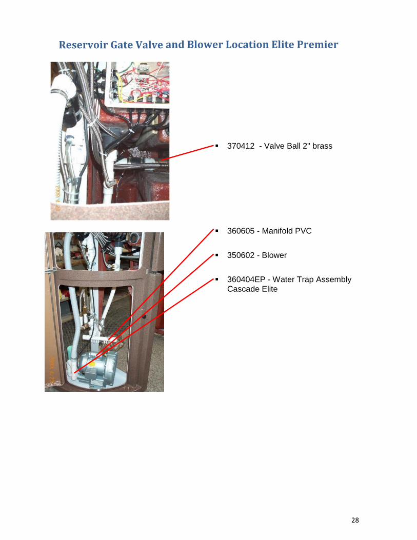
Reservoir Gate Valve and Blower Location Elite Premier
370412 - Valve Ball 2" brass
360605 - Manifold PVC
350602 - Blower
360404EP - Water Trap Assembly Cascade Elite
29
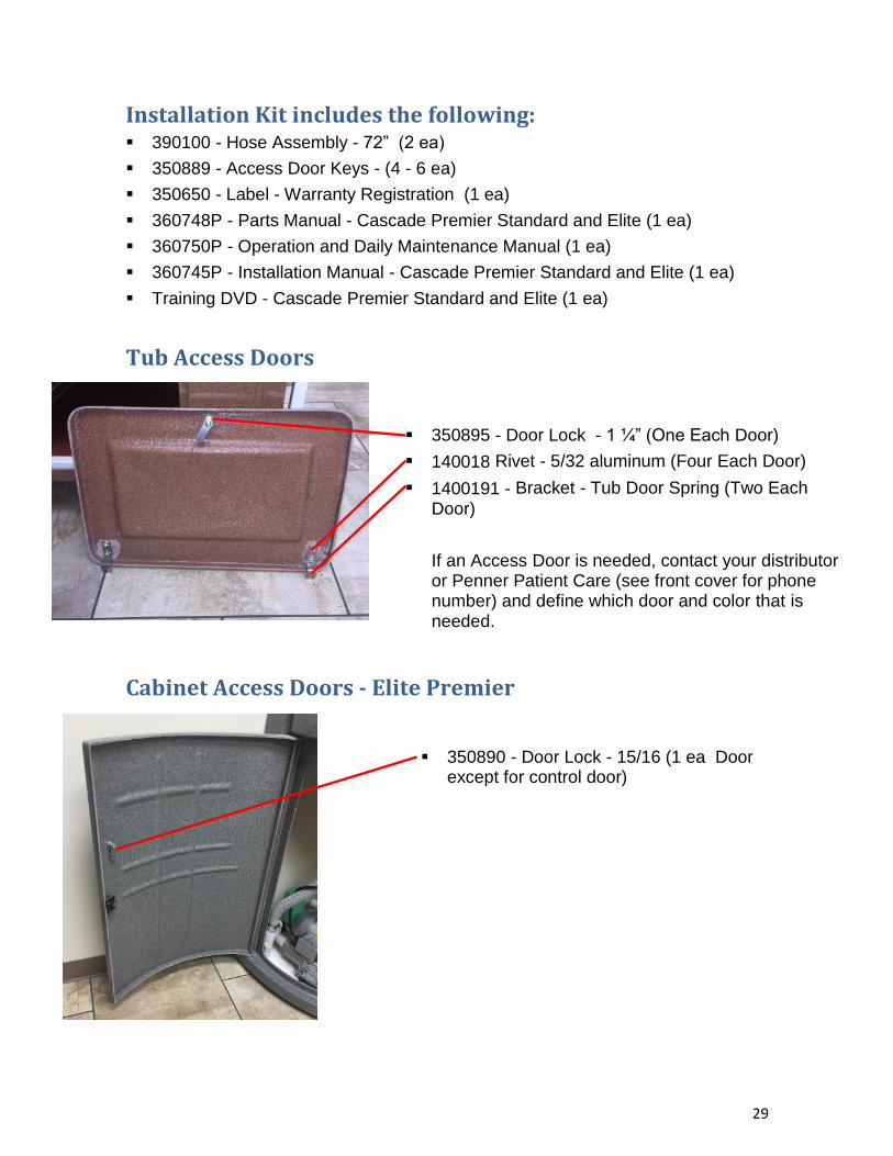
Installation Kit includes the following: 390100 - Hose Assembly - 72” (2 ea)
350889 - Access Door Keys - (4 - 6 ea)
350650 - Label - Warranty Registration (1 ea)
360748P - Parts Manual - Cascade Premier Standard and Elite (1 ea)
360750P - Operation and Daily Maintenance Manual (1 ea)
360745P - Installation Manual - Cascade Premier Standard and Elite (1 ea)
Training DVD - Cascade Premier Standard and Elite (1 ea)
Tub Access Doors
Cabinet Access Doors - Elite Premier
350890 - Door Lock - 15/16 (1 ea Door except for control door)
350895 - Door Lock - 1 ¼” (One Each Door)
140018 Rivet - 5/32 aluminum (Four Each Door)
1400191 - Bracket - Tub Door Spring (Two Each
Door)
If an Access Door is needed, contact your distributor or Penner Patient Care (see front cover for phone number) and define which door and color that is needed.
30
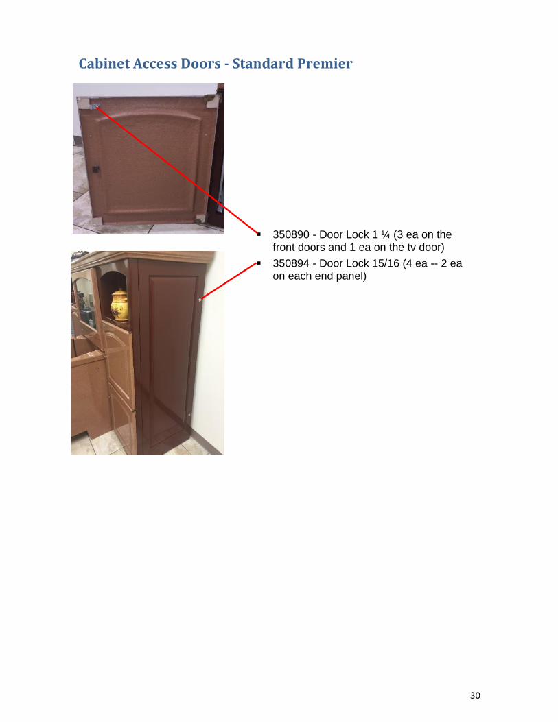
Cabinet Access Doors - Standard Premier
350890 - Door Lock 1 ¼ (3 ea on the front doors and 1 ea on the tv door)
350894 - Door Lock 15/16 (4 ea -- 2 ea on each end panel)

31

32
Your Penner distributor and his personnel are trained to provide in-service instruction and maintenance information on your Cascade bath system. If you have
any questions about the operation or maintenance of your Cascade bath system, please contact your Penner distributor. For your nearest Penner distributor, contact
Penner Patient Care, Inc.
at
1-800-732-0717 OR 1-866-736-6377