Embed Size (px)
Citation preview

ENGLISH - ESPAÑOL
609654Rev. 02 (10-04)
Model No.:609541609542 -- Pac
FS-2000Battery Automatic Scrubber
Fregadora Automática Batería
Operator and Parts ManualManual de Operación y de Piezas
CASTEX CUSTOMER SERVICE:1--800--365--6625
FAX: 1--800--678--4240
TECHNICAL SUPPORT:1--800--522--7839 EXT. 5356
TENNANT COMPANY701 NORTH LILAC DRIVEMINNEAPOLIS, MN 55422
MAILING ADDRESS:TENNANT COMPANYP.O. BOX 1452MINNEAPOLIS, MN 55440--1452

OPERATION
2 FS-2000 Battery Scrubber (10--04)
This manual is furnished with each new model.It provides necessary operation and maintenanceinstructions and an illustrated parts list.
Read this manual completely and understand themachine before operating or servicing.
Use the illustrated Parts Lists to order parts. Beforeordering parts or supplies, be sure to have yourmachine model number and serial number handy.Parts and supplies may be ordered by phone or mailfrom any authorized parts and service center,distributor or from any of the manufacturer’ssubsidiaries.
This machine will provide excellent service. However,the best results will be obtained at minimum costs if:
S The machine is operated with reasonable care.
S The machine is maintained regularly - per themaintenance instructions provided.
S The machine is maintained with manufacturersupplied or equivalent parts.
MACHINE DATA
Please fill out at time of installation for future reference.
Model No.-
Install. Date -
Serial No.-
E2000, 2001, 2004 Tennant Company Printed in U.S.A.
Castex is a registered United States trademark of Tennant Company.Specifications and parts are subject to change without notice.
TABLE OF CONTENTS (ESPAÑOL ÍNDICE....17)
SAFETY PRECAUTIONS 3. . . . . . . . . . . . . . . . . . . .
SAFETY LABELS 4. . . . . . . . . . . . . . . . . . . . . . . . . . .
MACHINE COMPONENTS 5. . . . . . . . . . . . . . . . . . .
MACHINE INSTALLATION 6. . . . . . . . . . . . . . . . . . .UNCRATING MACHINE 6. . . . . . . . . . . . . . . . . .INSTALLING BATTERIES 6. . . . . . . . . . . . . . . .
MACHINE SETUP 7. . . . . . . . . . . . . . . . . . . . . . . . . .PRE--OPERATION CHECKS 7. . . . . . . . . . . . . .ATTACHING SQUEEGEE 7. . . . . . . . . . . . . . . .INSTALLING BRUSH OR PAD DRIVER 7. . . .FILLING SOLUTION TANK 8. . . . . . . . . . . . . . .
MACHINE OPERATION 9. . . . . . . . . . . . . . . . . . . . .WHILE OPERATING MACHINE 9. . . . . . . . . . .BRUSH MOTOR CIRCUIT BREAKER 10. . . . . .
DRAINING TANKS 10. . . . . . . . . . . . . . . . . . . . . . . . . .DRAINING RECOVERY TANK 10. . . . . . . . . . . .DRAINING SOLUTION TANK 11. . . . . . . . . . . . .
CHARGING BATTERIES 11. . . . . . . . . . . . . . . . . . . .
MACHINE MAINTENANCE 12. . . . . . . . . . . . . . . . . .DAILY MAINTENANCE 12. . . . . . . . . . . . . . . . . . .WEEKLY MAINTENANCE 13. . . . . . . . . . . . . . . .MONTHLY MAINTENANCE 13. . . . . . . . . . . . . . .QUARTERLY MAINTENANCE 13. . . . . . . . . . . .BATTERY MAINTENANCE 13. . . . . . . . . . . . . . .
TRANSPORTING MACHINE 14. . . . . . . . . . . . . . . . .
STORING MACHINE 14. . . . . . . . . . . . . . . . . . . . . . . .
RECOMMENDED STOCK ITEMS 14. . . . . . . . . . . . .
TROUBLE SHOOTING 15. . . . . . . . . . . . . . . . . . . . . .
SPECIFICATIONS 16. . . . . . . . . . . . . . . . . . . . . . . . . .
ELECTRICAL DIAGRAMS 34. . . . . . . . . . . . . . . . . . .
PARTS LIST 36. . . . . . . . . . . . . . . . . . . . . . . . . . . . . . . .REPLACEMENT BRUSHES AND PAD DRIVERGROUP 36. . . . . . . . . . . . . . . . . . . . . . . . . . . . . . . .SOLUTION TANK GROUP 38. . . . . . . . . . . . . . . .SOLUTION TANK REAR PANEL GROUP 40. .RECOVERY TANK GROUP 42. . . . . . . . . . . . . . .CONTROL CONSOLE GROUP 44. . . . . . . . . . .LEVER GROUP 46. . . . . . . . . . . . . . . . . . . . . . . . .NON-DRIVE MODEL WHEEL GROUP 48. . . . .BRUSH DRIVE GROUP 50. . . . . . . . . . . . . . . . . .SKIRT GROUP 52. . . . . . . . . . . . . . . . . . . . . . . . . .CURVED SQUEEGEE GROUP 54. . . . . . . . . . .
OPTIONS 56. . . . . . . . . . . . . . . . . . . . . . . . . . . . . . . . . . .ESr KIT 56. . . . . . . . . . . . . . . . . . . . . . . . . . . . . . . .SQUEEGEE WAND ASSEMBLY 58. . . . . . . . . .BRUSH WEIGHT KIT 59. . . . . . . . . . . . . . . . . . . .

OPERATION
FS-2000 Battery Scrubber (10--04) 3
SAFETY PRECAUTIONS
This machine is intended for commercial use. It isdesigned exclusively to scrub hard floors in anindoor environment and is not constructed for anyother use. Use only recommended pads, brushesand commercially available floor cleanersintended for machine application.
All operators must read, understand and practicethe following safety precautions.
The following warning alert symbol and the “FORSAFETY” heading are used throughout this manual asindicated in their description:
WARNING: To warn of hazards or unsafepractices which could result in severe personalinjury or death.
FOR SAFETY: To identify actions which must befollowed for safe operation of equipment.
Failure to follow these warnings may result in:personal injury, electrocution, electrical shock,fire or explosion.
WARNING: Do Not Use Flammable Liquids OrOperate Machine In Or Near Flammable Liquids,Vapors Or Combustible Dusts.
This machine is not equipped with explosionproof motors. The electric motors will spark uponstart up and during operation which could cause aflash fire or explosion if machine is used in anarea where flammable vapors/liquids orcombustible dusts are present.
WARNING: Do Not Pick Up FlammableMaterials Or Reactive Metals.
WARNING: Keep Sparks And Open FlameAway. Keep Battery Hood Open When Charging.
WARNING: Disconnect Battery Cables BeforeServicing Machine.
The following information signals potentiallydangerous conditions to the operator orequipment:
FOR SAFETY:
1. Do not operate machine:-- With flammable liquids or near flammable
vapors as an explosion or flash fire mayoccur.
-- Unless trained and authorized.-- Unless operation manual is read and
understood.-- If not in proper operating condition.
2. Before starting machine:-- Make sure all safety devices are in place
and operate properly.
3. When using machine:-- Go slow on inclines and slippery surfaces.-- Wear non--slip shoes.-- Reduce speed when turning.-- Report machine damage or faulty
operation immediately.-- Never allow children to play on or around.-- Follow mixing and handling instructions
on chemical containers.
4. Before leaving or servicing machine:-- Stop on level surface.-- Turn off machine.
5. When servicing machine:-- Avoid moving parts. Do not wear loose
jackets, shirts, or sleeves.-- Block machine tires before jacking up.-- Use hoist or jack that will support the
weight of the machine.-- Wear eye and ear protection when using
pressurized air or water.-- Disconnect battery connections before
working on machine.-- Wear protective gloves and safety glasses
when handling batteries or battery cables.-- Avoid contact with battery acid.-- Use manufacturer supplied or approved
replacement parts.-- All repairs must be performed by a
qualified service person.-- Do not modify the machine from its
original design.
6. When transporting machine:-- Turn machine off.-- Get assistance when lifting machine.-- Do not lift machine when batteries are
installed.-- Use a recommended ramp when
loading/unloading into/off truck or trailer.-- Use tie--down straps to secure machine to
truck or trailer.

OPERATION
4 FS-2000 Battery Scrubber (10--04)
SAFETY LABELS
The safety labels appear on the machine in the locations indicated. Replace labels if they are missing or becomedamaged or illegible.
WARNING LABEL -- LOCATED ON THE RECOVERYTANK COVER.
BATTERY CHARGE LABEL --LOCATED INSIDE BATTERYCOMPARTMENT.
WARNING: Keep sparks and openflame away. Keep battery hoodopen when charging.

OPERATION
FS-2000 Battery Scrubber (10--04) 5
MACHINE COMPONENTS
23
5
8
14
1
6 7
12
10 9
13
11
15
20
16
14
7
19
2221
176
18
4
1. Control Grips
2. Vacuum ON/OFF Switch
3. Brush ON/OFF Switch
4. Battery Meter
5. Brush Circuit Breaker
6. Squeegee Lift Lever
7. Solution Flow Lever
8. Solution Flow Adjustment Knob
9. Adjustable Control Console Levers
10. Brush Lift Lever
11. Brush Lift Foot Lever
12. Recovery Tank Drain Hose
13. Solution Tank Drain Hose
14. Squeegee Assembly
15. Control Console
16. Recovery Tank
17. Recovery Tank Lid
18. Solution Fill Door
19. Safety Lights
20. Rear Drive Wheel
21. Scrub Head
22. Scrub Head Skirt

OPERATION
6 FS-2000 Battery Scrubber (10--04)
MACHINE INSTALLATION
UNCRATING MACHINE
Carefully check carton for signs of damage. Reportdamages at once to carrier. Check carton contents toensure all accessories are included. MorganShepherd?
To uncrate your machine, remove straps and raisebrush head. To raise brush head, step down firmly onthe bottom brush lift foot pedal until pedal locks intothe raised position. Carefully lift or create a ramp usingcrate boards to remove machine from pallet.
ATTENTION: Do not roll machine off pallet,damage may occur.
ATTENTION: To prevent machine damage, installbatteries after removing machine from pallet.
INSTALLING BATTERIES
WARNING: Keep Sparks And Open FlameAway. Keep Battery Hood Open When Charging.
FOR SAFETY: When servicing machine, wearprotective gloves and safety glasses whenhandling batteries and battery cables. Avoidcontact with battery acid.
Recommended Battery Specifications:
Two 12 volt, deep cycle, 130 amp hour batteries.Maximum battery dimensions are 180mm (7.13 in) Wx 330mm (13 in) L x 254mm (10 in) H.
1. Turn all switches to the off position.
2. Carefully hinge open recovery tank to accessbattery compartment. Make sure recovery tank isempty before opening. Remove loose batterycable and PVC battery spacer from compartment(Figure 1).
FIG. 1
3. Carefully install batteries into compartment andarrange battery posts as shown (Figure 2).
FIG. 2
ATTENTION: Do not drop batteries intocompartment! Battery and machine housingdamage may result.
4. To secure batteries, place white PVC tube spacer‘‘A” behind batteries in compartment (Figure 2).
5. Connect cables to battery posts in numerical orderas labeled (RED to POSITIVE and BLACK toNEGATIVE) (Figure 2).
6. Apply a light coating of non--metallic grease orprotective spray on the cable connections toprevent battery corrosion.

OPERATION
FS-2000 Battery Scrubber (10--04) 7
MACHINE SETUP
PRE--OPERATION CHECKS
1. Sweep and dust mop floor.
2. Check battery meter charge level to ensurebatteries are fully charged (See BATTERYCHARGING).
3. Check that a pad/brush is installed.
4. Check that squeegee is installed.
ATTACHING SQUEEGEE
1. Pull back on squeegee lift lever to raise squeegeemount bracket.
2. Loosen two thumb knobs on squeegee and slidesqueegee into slot at rear of squeegee mountbracket. Make sure that squeegee roller wheelsare facing toward the rear (Figure 3).
FIG. 3
3. Tighten thumb knobs securely.
INSTALLING BRUSH OR PAD DRIVER
1. Turn machine off.
FOR SAFETY: Before leaving or servicingmachine, stop on level surface and turn offmachine.
2. Lower brush head. Step down firmly on top pedaland push pedal forward to lower (Figure 4).
FIG. 4
3. Position squeegee swivel mechanism so it’scentered behind machine.
4. Tilt machine back to access motor hub.
ATTENTION: Do not leave machine tilted back foran extended time. Battery acid may leak.
5. Select a recommended pad or brush that bestmeets your cleaning needs.
NOTE: Consult your authorized distributor for pad andbrush recommendations.
6. (For Pad Installation) Attach pad to pad driverbefore installing driver to motor hub. To attachpad, remove plastic centerlock from pad driverand position pad centered on driver, replacecenterlock securely (Figure 5).
FIG. 5

OPERATION
8 FS-2000 Battery Scrubber (10--04)
7. Attach brush/pad driver to motor hub. Align 3mounting studs with slots in motor hub and givethe driver a quick turn toward the spring clip on themotor hub to attach brush/pad driver. Be certainthat spring clip locks into one of the studs on thedriver before operating machine (Figure 6).
FIG. 6
8. Raise brush head. To raise brush head, step downfirmly on the bottom brush lift foot pedal until brushlocks into the raised position (Figure 7).
FIG. 7
FILLING SOLUTION TANK
1. Push machine to fill station. Raise squeegee andbrush head when transporting.
2. Pull solution flow lever completely back to shut offsolution flow (Figure 8).
FIG. 8
3. Open solution fill door at front of machine and fillsolution tank with 38L (10 gal) of clean water,60°C (140°F) maximum temperature. Or use therear fill port to fill solution tank. The clear tubebelow the fill port has 19L (5 gal) incrementmarkers to indicate amount of water in tank(Figure 9).
NOTE: The water must not be hotter than 60_C(140_F) or tank damage may occur.
FIG. 9
NOTE: If filling with a bucket be certain that bucket isclean. This will prevent possible solution line clogs.
4. Add cleaning chemical. See proper dilution ratioinstructions on bottle.
FOR SAFETY: When using machine, follow mixingand handling instructions on chemical containers.
ATTENTION: Use only recommended detergents.Machine damage due to improper detergent usagewill void the manufacturer’s warranty. Contactyour Tennant Sales Representative for detergentrecommendations.
WARNING: Do Not Use Flammable Liquids OrOperate Machine In Or Near Flammable Liquids,Vapors Or Combustible Dusts.

OPERATION
FS-2000 Battery Scrubber (10--04) 9
MACHINE OPERATION
FOR SAFETY: Do not operate machine unlessoperator manual is read and understood.
1. Adjust control grips to a comfortable operatingheight (three settings). Squeeze together twolevers under console to raise or lower control grips(Figure 10).
FIG. 10
2. Lower squeegee by releasing squeegee lift leverfrom the lock position (Figure 11).
FIG. 11
3. Lower brush head, step down firmly on top brushlift pedal and push pedal forward to lower(Figure 12).
FIG. 12
4. Turn vacuum switch to the on position.
5. Push solution flow lever forward to desired flowrate. Solution will immediately begin to flow oncelever is activated (Figure 13).
FIG. 13
To adjust the maximum solution flow rate, turnsolution flow adjustment knob down to increase orup to decrease (Figure 14).
FIG. 14
6. Turn brush switch to the on position.
ATTENTION: To prevent floor finish damage, DONOT leave machine at stand still once brushbegins to spin.
7. Begin scrubbing by pushing machine forward.
WHILE OPERATING MACHINE
WARNING: Do Not Pick Up FlammableMaterials Or Reactive Metals.
FOR SAFETY: When using machine, go slow oninclines and slippery surfaces.
1. Periodically check for excessive foam in recoverytank (look through clear lid). If excessive foamappears, pour a foam control solution into therecovery tank.
ATTENTION: Do not allow foam or water to enterfloat shut-off screen, vacuum motor damage willresult; not covered by warranty. Foam will notactivate float shut-off screen.

OPERATION
10 FS-2000 Battery Scrubber (10--04)
2. If more scrubbing pressure is needed for smallheavily soiled areas, simply pull brush lift leverupward while operating (Figure 15).
FIG. 15
3. If squeegee leaves streaks, raise squeegee andwipe both blades with a cloth.
4. Before stopping or turning machine around, pullback on solution control lever to shut off solutionflow.
5. View clear tube at rear of machine for remainingcleaning solution.
6. Periodically check battery meter’s discharge level.When needle drops to the red zone, rechargebatteries.
ATTENTION: Do not operate machine with thebattery meter in the red zone, battery damage mayresult.
7. When the solution tank runs dry, turn off brushswitch, shut off solution control lever and continueto vacuum until all dirty water is consumed into therecovery tank. Raise the squeegee and brushhead and drain recovery tank (See DRAININGTANKS).
BRUSH MOTOR CIRCUIT BREAKER
Machine is equipped with a circuit breaker to protectbrush motor from damage. If the brush motor circuitbreaker trips, it can not be reset immediately.Determine reason why breaker tripped, allow motor tocool and then reset. Circuit breaker will trip due tobrush motor overload. Clean or change pad if breakershould trip. Brush motor circuit breaker button islocated at rear of control console (Figure 16).
FIG. 16
DRAINING TANKS
1. Turn machine off.
FOR SAFETY: Before leaving or servicingmachine, stop on level surface and turn offmachine.
2. Raise squeegee and brush head and transportmachine to floor drain.
NOTE: If using bucket to drain machine, do not usesame bucket for filling solution tank.
DRAINING RECOVERY TANK
When finished scrubbing or when refilling solutiontank, recovery tank should be drained and cleaned.
ATTENTION: If recovery tank is not drained beforerefilling, foam or water may enter the float shut-offscreen and damage vacuum motor. Foam will notactivate float shut--off screen.
1. Remove drain hose from holder, position hoseover floor drain and twist off drain hose plug. Tocompletely drain recovery tank, hinge open tankand flip up tank support stand to rest tank on(Figure 17).
FIG. 17

OPERATION
FS-2000 Battery Scrubber (10--04) 11
2. Clean recovery tank after each use. Use a hose torinse out recovery tank. Be careful not to spraywater into float shut-off screen.
3. Replace drain hose plug tightly after draining.
DRAINING SOLUTION TANK
To drain leftover cleaning solution from solution tankperform the following steps:
1. Pull clear tube off hose barb at rear of machineand drain solution into floor drain or bucket(Figure 18).
FIG. 18
2. Rinse solution tank with clean water after eachuse. This will prevent clogging due to chemicalbuildup.
3. Push solution flow lever forward to rinse outsolution flow system.
4. Reconnect clear tube. Be certain tube iscompletely pushed on hose barb.
CHARGING BATTERIES
NOTE: Recharge batteries ONLY after a total of 30minutes of use or more. This will prolong battery life.
The following charging instructions are intendedfor chargers supplied with machine. Only use acharger with the following specifications toprevent battery damage.
CHARGER SPECIFICATIONS:
S OUTPUT VOLTAGE - 24 VOLTS
S OUTPUT CURRENT - 10 TO 20 AMPS MAXIMUM
S AUTOMATIC SHUTOFF CIRCUIT
S FOR DEEP CYCLE BATTERY CHARGING
NOTE: For optimum machine operation, keepbatteries charged at all times. Never let batteries set ina discharge condition.
WARNING: Batteries emit hydrogen gas.Explosion or fire can result. Keep sparks andopen flame away. Keep battery compartment openwhen charging.
FOR SAFETY: When servicing machine, wearprotective gloves when handling batteries andbattery cables. Avoid contact with battery acid.
1. Push machine to a well--ventilated area forcharging.
2. Turn machine off.
3. Hinge open recovery tank to access batteries.Make sure recovery tank is empty before opening(Figure 19).
FIG. 19
4. Before charging, check the fluid level (A) in eachbattery cell. If the battery plates (B) are exposed,add just enough distilled water to cover plates.DO NOT OVERFILL. Overfilled batteries canoverflow during charging due to fluid expansion.Replace cell caps before charging (Figure 20).
A
B
FIG. 20

OPERATION
12 FS-2000 Battery Scrubber (10--04)
5. With charger’s power supply cord unplugged,connect battery charger into machine as shown.Flip up hood support stand and rest hood on standto promote ventilation (Figure 21).
FIG. 21
6. Plug the charger’s power supply cord into agrounded wall outlet (Figure 22).
Grounded3 Hole Outlet
Ground Pin
FIG. 22
FOR SAFETY: Do not operate charger unless cordis properly grounded.
WARNING: Keep Sparks And Open FlameAway. Keep Battery Hood Open When Charging.
NOTE: Once the charger is connected, machinebecomes inoperable.
7. The charger will automatically begin charging andshut off when fully charged.
8. When disconnecting charger, always unplugcharger from wall outlet first.
9. After charging, recheck the battery fluid level (A) ineach battery cell. The level should be 1 cm (3/8 in)from the bottom of sight tubes (B). Add distilledwater if needed. DO NOT OVERFILL (Figure 23).
AB
FIG. 23
MACHINE MAINTENANCE
To keep machine in good working condition, simplyfollow machines daily, weekly and monthlymaintenance procedures.
FOR SAFETY: Before leaving or servicingmachine, stop on level surface and turn offmachine.
WARNING: Disconnect Battery Cables BeforeServicing Machine.
ATTENTION: Contact an Authorized ServiceCenter for machine repairs. Machine repairsperformed by other than an authorized person willvoid your warranty.
DAILY MAINTENANCE(Every 4 Hours of Use)
1. Remove and clean pad/brush.
2. Remove and clean float shut-off screen located inrecovery tank (Figure 24).
FIG. 24
3. Drain and rinse tanks thoroughly. After drainingtanks, hinge recovery tank until you can seevacuum intake hole at rear of tank. Remove anydebris in hole if necessary.
4. Raise squeegee and wipe it down with a dry cloth.Store squeegee in the up position to preventsqueegee damage.
5. Clean machine with an all purpose cleaner anddamp cloth.
ATTENTION: Do not power spray or hose offmachine. Electrical component damage mayresult.
6. Recharge batteries if necessary.

OPERATION
FS-2000 Battery Scrubber (10--04) 13
WEEKLY MAINTENANCE(Every 20 Hours of Use)
1. Check fluid level in battery cells (See BATTERYCHARGING).
2. Clean battery tops from corrosion (See BATTERYCHARGING).
3. Check for loose or corroded battery cables.
MONTHLY MAINTENANCE(Every 80 Hours of Use)
1. Lubricate all linkage pivot points with silicon spraythen coat with a water resistant grease to maintaina smooth operation.
2. Check machine for water leaks and loose nuts andbolts.
QUARTERLY MAINTENANCE(Every 250 Hours of Use)
Inspect motors for carbon brush wear. Replacebrushes when worn to a length of 10mm (0.38 in.) orless. Contact an Authorized Service Center for carbonbrush inspection.
ATTENTION: Contact an Authorized ServiceCenter for machine repairs. Machine repairsperformed by other than an authorized person willvoid the warranty.
BATTERY MAINTENANCE
WARNING: Keep Sparks And Open FlameAway. Keep Battery Hood Open When Charging.
FOR SAFETY: When servicing machine, wearprotective gloves and safety glasses whenhandling batteries and battery cables. Avoidcontact with battery acid.
1. Always follow proper charging instructions(see CHARGING BATTERIES).
2. Check fluid level (A) in each battery cell. The fluidlevel should be 1 cm (3/8 in.) from the bottom ofsight tubes after charging. Add distilled water ifneeded. DO NOT OVERFILL. Overfilled batteriescan overflow during charging due to fluidexpansion (Figure 25).
A
FIG. 25
3. After charging batteries, measure the specificgravity in each battery cell using a hydrometer(Figure 26). This will determine the charge leveland condition of the batteries. If one or more ofthe battery cells test lower than the other batterycell (0.050 or more), the cell is damaged,shortened, or is about to fail.
NOTE: Do not take reading immediately after addingdistilled water. The water and acid must be thoroughlymixed in order for accurate reading.
FIG. 26
SPECIFIC GRAVITYat 27°C (80°F)
BATTERYCHARGE
1.265 100% CHARGED
1.223 75% CHARGED
1.185 50% CHARGED
1.148 25% CHARGED
1.110 DISCHARGED
NOTE: Add or subtract 0.004 gravity reading for each6_C (10_F) above or below 27_C (80_F).

OPERATION
14 FS-2000 Battery Scrubber (10--04)
4. Keep battery tops and terminals clean and dry.a. Mix a strong solution of baking soda and water
(Figure 27).
FIG. 27
b. Brush solution sparingly over battery tops,terminals, and cable connectors.
NOTE: Do not allow baking soda solution to enterbattery cells.c. Use wire brush to clean terminals and cable
connections.d. After cleaning, apply a coating of clear battery
post protectant to terminals and cableconnections.
5. Check for loose or worn cables. Replace if worn.
TRANSPORTING MACHINE
When transporting machine by use of trailer or truck,be certain to follow tie--down procedures below:
FOR SAFETY: When using machine, go slow oninclines and slippery surfaces.
1. Raise squeegee and scrub head.
2. Load machine using a recommended loadingramp.
3. Position front of machine up against front of traileror truck. Once machine is positioned, lower scrubhead and squeegee.
4. Place a block behind the main wheel and the rearcasters.
5. Place tie--down straps over top of machine andsecure straps to floor. It may be necessary toinstall tie--down brackets to the floor of your traileror truck.
NOTE: Do not use control grips to secure machine fortransporting.
FOR SAFETY: When transporting machine, use arecommended ramp when loading/unloadinginto/off truck or trailer, use tie--down straps tosecure machine to truck or trailer.
STORING MACHINE
1. Charge batteries before storing. Never storemachine with discharged batteries.
2. Drain and rinse tanks thoroughly.
3. Store machine in a dry area with squeegee andscrub head in the raised position.
4. Remove recovery tank lid to promote aircirculation.
ATTENTION If storing machine in freezingtemperatures, be certain to drain machine of allwater. Damage due to freezing temperatures is notcovered by warranty.
ATTENTION: Do not expose machine to rain; storeindoors.
RECOMMENDED STOCK ITEMS
Refer to Parts List section for recommended stockitems. Stock Items are clearly identified with a bulletpreceding the parts description. See example below:

OPERATION
FS-2000 Battery Scrubber (06--99) 15
TROUBLE SHOOTING
PROBLEM CAUSE SOLUTIONNo power. Batteries need charging. See Battery Charging.p
Battery(s) faulty. Replace battery(s)Loose battery cable. Tighten loose cables.Batteries are not connectedcorrectly.
See Battery Installation.
Brush motor does not run. Faulty brush switch. Contact Service Center.Machine circuit breaker has tripped. Clean or replace pad or brush and
reset breaker button.Rectifier has burned out. Contact Service Center.Faulty wiring. Contact Service Center.Faulty brush motor. Contact Service Center.Carbon brushes worn. Contact Service Center.Faulty solenoid. Contact Service Center.
Vacuum motor does not run. Faulty vacuum switch or wiring. Contact Service Center.Faulty vacuum motor. Contact Service Center.Carbon brushes worn. Contact Service Center.
Short run time. Batteries not fully charged. Charge batteries.
(Run time 2.47 hours on full charge) Bad cell in one or more batteries. Replace battery.( u t e ou s o u c a ge)Batteries need maintenance. See Battery Maintenance.Faulty charger. Replace charger.
Safety lights do not work. Flasher is burned out. Contact Service Center.
Little or no solution flow. Solution flow lever is not activated. Push solution flow lever forward.Solution line is clogged. Remove hose and blow
compressed air through it.Solution valve is clogged. Remove valve and clean. Do not
scratch or damage inside of valve.Solution flow adjustment knobneeds adjusting.
Adjust solution flow knob toincrease solution flow. Turn knobdown to increase flow.

OPERATION
16 FS-2000 Battery Scrubber (06--99)
TROUBLE SHOOTING -- CONTINUED
PROBLEM CAUSE SOLUTIONPoor water pick up. Recovery tank is full. Empty recovery tank.p p
Ball float shutoff screen insiderecovery tank is clogged.
Remove screen and clean.
Squeegee is clogged with debris. Clean squeegee.Squeegee blades are worn. Replace squeegee blades.Squeegee thumbscrews are loose. Tighten thumbscrews.Vacuum hose connections areloose or hose has a hole.
Push vacuum hose cuffs firmly onconnections. Replace hose ifdamaged.
Vacuum hose is clogged withdebris.
Remove clogged debris.
Tank gasket is defective. Replace tank gasket.Recovery tank water inlet isplugged. Inlet is located at bottomof recovery tank.
Empty recovery tank and tilt itsideways to locate inlet hole,remove clogged debris.
Drain hose plug is loose. Tighten drain plug.Clear recovery tank lid is loose. Tighten lid.Vacuum motor is loose. Tighten down vacuum motor. Do
not over tighten and damage motor.Battery charge is low. Charge batteries. Do not run
machine when battery meter is inthe red zone.
SPECIFICATIONS
Model FS-2000LENGTH 1194 mm (47 in)
WIDTH 559 mm (22 in)
HEIGHT 965 mm (38 in)
WEIGHT 146 Kg (315 lb)
SOLUTION TANK CAPACITY 38 L (10 gal)
RECOVERY TANK CAPACITY 45 L (12 gal)
CLEANING PATH WIDTH 508 mm (20 in)
BRUSH MOTOR .75hp, 220 rpm, 24v, 20A, 560w
VACUUM MOTOR .5hp, 2 stage, 353w, 14A, 24v
WATER LIFT 1118 mm (44 in)
BATTERIES 2--130A/hr, 12v deep cycle
RUN TIME on full charge 2.47 hours
DECIBEL RATING AT OPERATOR’S EAR, INDOORS ON TILE 70dB(A)

OPERACIÓN
17FS--2000 Batería (10--04)
Este manual acompaña a todos los modelos estándarnuevos. En él se indican las instrucciones necesariaspara la utilización y el mantenimiento de la máquina.
Lea el manual entero para comprender elfuncionamiento de la máquina antes de utilizarla orevisarla.
Esta máquina le proporcionará un servicio excelente.Sin embargo, obtendrá los mejores resultados al costemínimo si:
S Utiliza la máquina con un cuidado razonable.
S Revisa la máquina periódicamente - según lasinstrucciones de mantenimiento adjuntas.
S La máquina recibe mantenimiento con las piezas derepuesto del fabricante o equivalentes.
DATOS DE LA MÁQUINA
Por favor complete en el momento de la instalación,para referencia futura.
No. de modelo --
Fecha de instalación --
Nº de Serie--
ÍNDICE
MEDIDAS DE SEGURIDAD 18. . . . . . . . . . . . . . . . . .
ROTULOS DE SEGURIDAD 19. . . . . . . . . . . . . . . . .
COMPONENTES DE LA MÁQUINA 20. . . . . . . . . . .
INSTALACIÓN DE LA MÁQUINA 21. . . . . . . . . . . . .DESEMBALADO DE LA MÁQUINA 21. . . . . . . .INSTALACIÓN DE LA BATERÍA 21. . . . . . . . . . .
PREPARACIÓN DE LA MÁQUINA 22. . . . . . . . . . . .COMPROBACIONES PREVIAS A LA PUESTAEN FUNCIONAMIENTO 22. . . . . . . . . . . . . . . . . .FIJACIÓN DE LA ESCOBILLA DE GOMA 22. .INSTALACIÓN DEL IMPULSOR DEL CEPILLO ODE LA ALMOHADILLA 22. . . . . . . . . . . . . . . . . . .LLENADO DEL DEPÓSITO DE LADISOLUCIÓN 23. . . . . . . . . . . . . . . . . . . . . . . . . . .
FUNCIONAMIENTO DE LA MÁQUINA 24. . . . . . . .DURANTE LA UTILIZACIÓN DE LAMÁQUINA 25. . . . . . . . . . . . . . . . . . . . . . . . . . . . . .CORTACIRCUITOS DEL MOTOR DE LAALMOHADILLA 25. . . . . . . . . . . . . . . . . . . . . . . . .
VACIADO DE LOS DEPÓSITOS 26. . . . . . . . . . . . . .VACIADO DEL DEPÓSITO DERECUPERACIÓN 26. . . . . . . . . . . . . . . . . . . . . . .VACIADO DEL DEPÓSITO DE LADISOLUCIÓN 26. . . . . . . . . . . . . . . . . . . . . . . . . . .
CARGA DE LA BATERÍA 27. . . . . . . . . . . . . . . . . . . .
MANTENIMIENTO DE LA MÁQUINA 28. . . . . . . . .MANTENIMIENTO DIARIO 28. . . . . . . . . . . . . . .MANTENIMIENTO SEMANAL 28. . . . . . . . . . . . .MANTENIMIENTO MENSUAL 29. . . . . . . . . . . .MANTENIMIENTO TRIMESTRAL 29. . . . . . . . .MANTENIMIENTO DE LA BATERÍA 29. . . . . . .
TRANSPORTE DE LA MÁQUINA 30. . . . . . . . . . . . .
ALMACENAMIENTO DE LA MÁQUINA 30. . . . . . .
RECOMENDACIONES PARA ELALMACENAMIENTO 30. . . . . . . . . . . . . . . . . . . . . . . .
LOCALIZACIÓN DE AVERÍAS 31. . . . . . . . . . . . . . .
ESPECIFICACIONES 33. . . . . . . . . . . . . . . . . . . . . . .
DIAGRAMAS ELECTRICAS 34. . . . . . . . . . . . . . . . .
LISTA DE PIEZAS 36. . . . . . . . . . . . . . . . . . . . . . . . . .CEPILLO DEL REEMPLAZO Y GRUPO DELMANDO DE LA ALMOHADILLA 36. . . . . . . . . . .GRUPE DEL DEPÓSITO DE DISOLUCIÓN 38.CONJUNTO PANEL TRASERA 40. . . . . . . . . . .CONJUNTO DESPÓSITO RECUPERAR 42. . .CONJUNTO CONSOLA DE CONTROLES 44. .CONJUNTO DE PALANCAS 46. . . . . . . . . . . . . .CONJUNTO PARA LEVANTAR CEPILLO 48. . .CONJUNTO IMPULSO DE CEPILLO 50. . . . . .CONJUNTO JUEGO 52. . . . . . . . . . . . . . . . . . . . .CONJUNTO PALETA ENCORUADO 54. . . . . . .
OPCIONES 56. . . . . . . . . . . . . . . . . . . . . . . . . . . . . . . .ESr JUEGO 56. . . . . . . . . . . . . . . . . . . . . . . . . . . .GROUPE D’ASPIRATION ET RACLETTEÀ MAIN 58. . . . . . . . . . . . . . . . . . . . . . . . . . . . . . . . .KIT DEL PESO DEL CEPILLO 59. . . . . . . . . . . .

OPERACIÓN
18 FS--2000 Batería (10--04)
MEDIDAS DE SEGURIDAD
Esta máquina está diseñada para el usocomercial. Se ha diseñado exclusivamente paralimpiar pisos duros en un ambiente interior y nose fabrica para ningún otro uso. Use sólolimpiadores recomendados de pisoscomercialmente disponibles para la aplicación dela máquina.
Todos los operadores deben leer, entender ypracticar las precauciones siguientes deseguridad.
El siguiente símbolo de alerta de advertencia y elencabezamiento de ”PARA SEGURIDAD” se usan eneste manual como se indica en su descripción:
ADVERTENCIA: Para advertir de riesgos oprácticas inseguras que podrían resultar enlesiones personales graves o la muerte.
PARA SEGURIDAD: Para identificar acciones quedeben seguirse para el funcionamiento seguro delequipo.
El no seguir estas advertencias puede resultar en:lesiones personales, electrocución, choqueeléctrico, fuego o explosión.
ADVERTENCIA: No use líquidos inflamablesni opere la máquina en o cerca de líquidos yvapores inflamables o polvos combustibles.
Esta máquina no está equipada con motores aprueba de explosión. Los motores eléctricosemiten chispas al arrancar y durante elfuncionamiento lo que podría causar un fuegoexplosivo o explosión si la máquina se usa en unaárea donde están presentes vapores/líquidosinflamables o polvos combustibles.
ADVERTENCIA: No aspire materialesinflamables o metales reactivos.
ADVERTENCIA: Mantenga alejada de chispasy llamas expuestas. Mantenga abierta la cubiertade la batería al cargar.
ADVERTENCIA: Desconecte los cables de labatería antes de prestar servicio a la máquina.
La información siguiente señala condicionespotencialmente peligrosas para el operador o elequipo:
PARA SEGURIDAD:
1. No opere la máquina:-- Con líquidos inflamables o cerca de los
vapores inflamables ya que puede ocurriruna explosión o fuego explosivo.
-- A menos que está capacitado y autorizado.-- A menos que se haya leído y entendido el
manual del funcionamiento.-- Si no está en condición de ejecutar una
operación apropiada.
2. Antes de arrancar la máquina:-- Asegúrese que todos los dispositivos de
seguridad están en su lugar y operandoapropiadamente.
3. Al usar máquina:-- Avance lentamente en las cuestas y
superficies resbaladizas.-- Use zapatos antiresbalosos.-- Sea precavido al retroceder la máquina.-- Informe inmediatamente acerca de daños
o un funcionamiento defectuoso.-- Nunca permita que los niños jueguen en o
alrededor de la máquina.-- Siga las instrucciones de mezcla y manejo
indicados en los recipientes químicos.
4. Antes de salir de o reparar la máquina:-- Deténgala en una superficie nivelada.-- Apague la máquina.
5. Al prestar servicio a la máquina:-- Evite las piezas móviles. No use
chaquetas, camisas, o mangas, holgadas.-- Calce las ruedas de la máquina antes de
levantarla con un gato.-- Use güinches o gatos para soportar el
peso de la máquina.-- Use protección de los ojos y oídos al usar
aire comprimido o agua.-- Desconecte las conexiones de la batería
antes de trabajar en la máquina.-- Use guantes protectores y lentes de
seguridad al manejar baterías o cables dela batería.

OPERACIÓN
19FS--2000 Batería (10--04)
-- Evite el contacto con el ácido de la batería.-- Use piezas de repuesto provistas o
aprobadas por el fabricante.-- Todas las reparaciones deben ser
realizadas por una persona de serviciocalificada.
-- No modifique la máquina de su diseñooriginal.
6. Al transportar máquina:-- Apague la máquina.-- Obtenga ayuda al alzar la máquina.-- No alce la máquina al instalar las baterías.-- Use una rampa recomendada al
cargar/descargar al/fuera del camión oremolque .
-- Use correas de amarre para asegurar lamáquina al camión o remolque.
ROTULOS DE SEGURIDAD
Los rótulos de seguridad aprecen en la máquina en las ubicaciones indicadas. Si los rótulos se dañan o son ilegibles,reempácelos.
ETIQUETA DE ADVERTENCIA -- LOCALIZADA EN ELTANQUE DE RECUPERACION.
ETIQUETA DE CARGA DE LABATERIA -- UBICADA DENTRODEL COMPARTIMIENTO DE LABATERIA.
ADVERTENCIA: Mantenga alejadade chispas y llamas expuestas.Mantenga abierta la cubierta de labatería al cargar.

OPERACIÓN
20 FS--2000 Batería (10--04)
COMPONENTES DE LA MÁQUINA
23
5
8
14
1
6 7
12
10 9
13
11
15
20
16
14
7
19
2221
176
18
4
1. Mandos de control
2. Interruptor de Encendido/Apagado (ON/OFF) dela aspiración
3. Interruptor de Encendido/Apagado (ON/OFF) delcepillo
4. Indicador del nivel de carga de la batería
5. Cortacircuitos del cepillo.
6. Palanca de elevación de la escobilla de goma
7. Palanca del flujo de la disolución
8. Botón de ajuste del flujo de la disolución
9. Palancas de ajuste de la consola de control
10. Palanca de elevación del cepillo
11. Pedal de elevación del cepillo
12. Manguera de vaciado del depósito derecuperación
13. Manguera de vaciado del depósito derecuperación con indicación en galones.
14. Conjunto de la escobilla de goma
15. Consola de control
16. Depósito de recuperación
17. Tapa del depósito de recuperación
18. Puerta de relleno de la disolución
19. Luces de seguridad
20. Rueda de tracción trasera
21. Cabezal de fregado
22. Aleta del cabezal de fregado
OPERACIÓN
21FS--2000 Batería (10--04)
INSTALACIÓN DE LA MÁQUINA
DESEMBALADO DE LA MÁQUINA
Compruebe cuidadosamente si la caja de cartónmuestra daños. En caso de que así sea informeinmediatamente de los daños al transportista. Controleel contenido de la caja para asegurarse que incluyetodos los accesorios.
Para desembalar la máquina retire las cintas y eleveel cabezal de barrido. Para elevar este cabezal pisefirmemente sobre la parte inferior del pedal deelevación del cepillo hasta que dicho pedal quedebloqueado en la posición elevada. Levante la máquinacon cuidado o utilice una rampa formada con lasplanchas de embalaje para retirar la máquina delpallet.
ATENCIÓN: No ruede equipo de pallet. Pudedanarse.
ATENCIÓN Para prevenir daños a la máquina,instalar las baterías después de extraer lamáquina de la tarima.
INSTALACIÓN DE LA BATERÍA
ADVERTENCIA: Mantenga alejada de chispasy llamas expuestas. Mantenga abierta la cubiertade la batería al cargar.
PARA SEGURIDAD: Al prestar servicio a lamáquina, use guantes protectores y lentes deseguridad al manejar las baterías o los cables dela batería. Evite el contacto con el ácido de labatería.
Especificaciones de la batería:
Dos baterías de 12 voltios de ciclo de 130 amp porhora. Pieza de numero 130869. Las dimensionesmáximas de las baterías son 180 mm x 330 mm x 254mm (ancho x alto x largo)
1. Retire la llave del contacto.
2. Abra con cuidado el depósito de recuperación ycolóquelo lateralmente girándolo sobre la bisagrapara poder acceder al compartimento de labatería. Extraiga del compartimento el cablesuelto de la batería y el espaciador de PVC de labatería (Figura 1).
FIG. 1
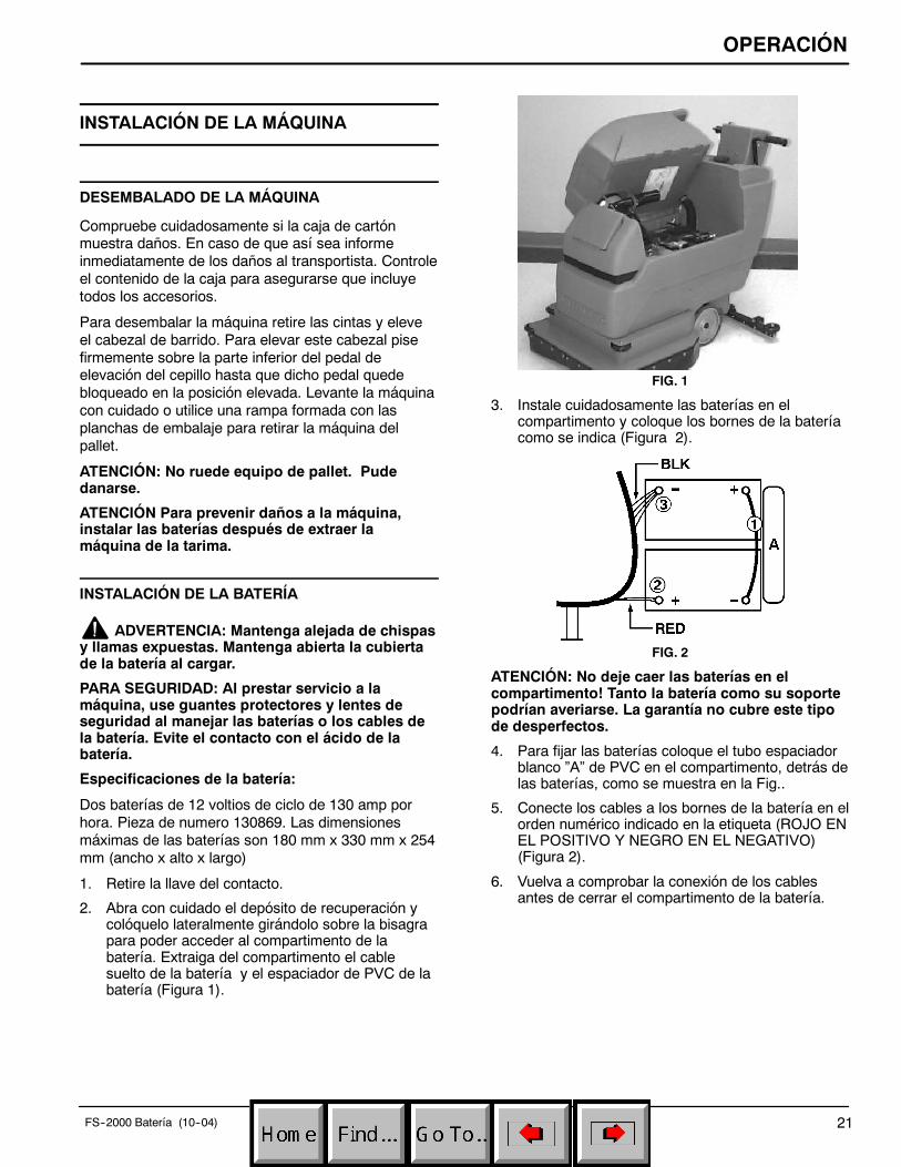
3. Instale cuidadosamente las baterías en elcompartimento y coloque los bornes de la bateríacomo se indica (Figura 2).
FIG. 2
ATENCIÓN: No deje caer las baterías en elcompartimento! Tanto la batería como su soportepodrían averiarse. La garantía no cubre este tipode desperfectos.
4. Para fijar las baterías coloque el tubo espaciadorblanco ”A” de PVC en el compartimento, detrás delas baterías, como se muestra en la Fig..
5. Conecte los cables a los bornes de la batería en elorden numérico indicado en la etiqueta (ROJO ENEL POSITIVO Y NEGRO EN EL NEGATIVO)(Figura 2).
6. Vuelva a comprobar la conexión de los cablesantes de cerrar el compartimento de la batería.

OPERACIÓN
22 FS--2000 Batería (11--01)
PREPARACIÓN DE LA MÁQUINA
COMPROBACIONES PREVIAS A LA PUESTA ENFUNCIONAMIENTO
1. Barra el suelo para eliminar partículas y otrosrestos.
2. Controle el nivel de carga de la batería paraasegurarse que de las baterías esténcompletamente cargadas en caso necesario(Consulte CARGA DE LAS BATERÍAS).
3. Controle que están instalados los cepillos oalmohadillas.
4. Controle que está instalada la escobilla de goma.
FIJACIÓN DE LA ESCOBILLA DE GOMA
1. Empuje hacia atrás la palanca de elevación de laescobilla de goma para elevar el soporte de laescobilla de goma.
2. Afloje los dos tornillos de orejas de la escobilla degoma e introduzca dicha escobilla deslizándola enlas ranuras de la parte posterior del soporte de laescobilla de goma. Asegúrese de que las ruedasdel rodillo de la escobilla de goma se encuentranhacia atrás (Figura 3).
FIG. 3
3. Fije los tornillos de orejas.
INSTALACIÓN DEL IMPULSOR DEL CEPILLO ODE LA ALMOHADILLA
1. Situúe la llave a la posición de apagado.
PARA SEGURIDAD: Al abandonar o revisar lamáquina, deténgase en una superficie plana,apague la máquina.
2. Baje el cabezal del cepillo, pise con fuerza la partesuperior del pedal y empuje dicho pedal haciadelante (Figura 4).
FIG. 4
3. Coloque el mecanismo de nivelación de laescobilla de goma de manera que se encuentrecentrado por la parte trasera de la máquina.
4. Levante la máquina sobre la escobilla de goma demanera que se pueda acceder al cubo del motorpara instalar el impulsor de cepillo/de laalmohadilla.
ATENCIÓN: No mantenga la máquina inclinadadurante mucho tiempo porque podría derramarseel ácido de la batería.
5. Seleccione el cepillo o la escobilla recomendadoque mejor se ajuste a sus necesidades.
NOTA: Consulte a su distribuidor autorizado para laelección del cepillo o de la almohadilla adecuadospara su caso específico.
6. (Instalación de la almohadilla) Fije laalmohadilla al impulsor de la almohadilla. Sujete laalmohadilla antes de instalar el impulsor de dichaalmohadilla en el cubo del motor. Retire el cierrecentral de plástico del impulsor de la almohadilla.Coloque la almohadilla en el centro del impulsorde la almohadilla y vuelva a colocar y fijar el cierrecentral (Figura 5).
FIG. 5

OPERACIÓN
23FS--2000 Batería (10--04)
7. Conecte el impulsor del cepillo o de la almohadillaal cubo del motor. Alinee los tres pernos demontaje con las ranuras del cubo del motor. Girerápidamente el impulsor hacia el sujetador deresorte del cubo del motor. Asegúrese de que elimpulsor de la almohadilla está bien sujeto y queel sujetador de resorte se introduzca en uno de lospernos del impulsor antes de poner la máquina enfuncionamiento (Figura 6).
FIG. 6
8. Elevación del cabezal de barrido: Pise firmementela parte inferior del pedal de elevación del cepillohasta que el cepillo quede bloqueado en laposición elevada (Figura 7).
FIG. 7
LLENADO DEL DEPÓSITO DE LA DISOLUCIÓN
1. Empuje o dirija la máquina a la estación dellenado. Levante la escobilla de goma y el cepillodurante el transporte.
2. Cierre del flujo de la disolución: Tire hacia atrás dela palanca del flujo de la disolución (Figura 8).
FIG. 8
3. Abra la puerta de llenado de la disolución que seencuentra en la parte delantera de la máquina yllene el depósito de la disolución con 10 galones (38litros) de agua limpia (temperatura máximade140_F/60_C). O utilice el orificio de llenadotrasero para llenar el depósito de la disolución. Eltubo transparente que se encuentra debajo delorificio de llenado tiene unas marcas cada 5 galones(19 litros) que indican el volumen de agua deldepósito (Figura 9).
NOTA: La temperatura del agua NO debe ser superiora los 60° C(140° F) ya que se podría dañar el tanque.
FIG. 9
NOTA: Si utiliza un cubo para llenar el depósito,asegúrese de que dicho cubo esté limpio para evitarque se obstruyan las tuberías de la disolución.
4. Añada el producto de limpieza. Consulte en lasinstrucciones del envase la proporción correcta dela disolución.
PARA SEGURIDAD: Al usar la máquina, observelas instrucciones de mezcla y manejo de losrecipientes de substancias químicas.
ATENCIÓN: Utilice únicamente productos delimpieza recomendados, NO utilice sustitutos.Consulte a un distribuidor autorizado acerca delos productos recomendados.
ADVERTENCIA: No use líquidos inflamablesni opere la máquina en o cerca de líquidos yvapores inflamables o polvos combustibles.

OPERACIÓN
24 FS--2000 Batería (11--01)
FUNCIONAMIENTO DE LA MÁQUINA
PARA SEGURIDAD: No opere la máquina a menosque haya leído y entendido el manual deloperador.
1. Ajuste los mandos de control a una altura demanejo cómoda (tres ajustes posibles). Presionelas dos palancas que se encuentran bajo laconsola para elevar o bajar los mandos de control(Figura 10).
FIG. 10
2. Baje la escobilla de goma liberando palanca deelevación de la escobilla de goma de su posiciónde bloqueo (Figura 11).
FIG. 11
3. Bajada del cabezal de barrido: Pise con fuerza laparte superior del pedal de elevación del cepillo yempuje dicho pedal hacia delante para liberarlo(Figura 12).
FIG. 12
4. Coloque el interruptor de aspiración en la posiciónde encendido (ON).
5. Empuje la palanca del flujo de la disoluciónligeramente hacia delante para activar el paso dela disolución. Cuanto más empuje dicha palancahacia delante mayor será el flujo de disolución.Empuje la palanca completamente para que elflujo sea máximo. La disolución empezará a fluirinmediatamente después de activar la palanca(Figura 13).
FIG. 13
Para aumentar o disminuir el flujo máximo de ladisolución gire el botón de ajuste del flujo de ladisolución. Gire el botón hacia abajo paraincrementar el flujo y hacia arriba para reducirlo(Figura 14).
FIG. 14
6 Coloque el interruptor de barrido en la posición deencendido (ON).
ATENCIÓN: Para evitar el deterioro del acabadodel suelo NO deje la máquina parada cuando loscepillos empiecen a girar.
7. Comience la operación de fregado empujando lamáquina hacia delante.

OPERACIÓN
25FS--2000 Batería (10--04)
DURANTE LA UTILIZACIÓN DE LA MÁQUINA
ADVERTENCIA: No aspire materialesinflamables o metales reactivos.
PARA SEGURIDAD: Conduzca despacio cuandoutilice la máquina en pendientes o superficiesresbaladizas.
1. Compruebe periódicamente que no existaacumulación de espuma en el depósito derecuperación (mire a través de la tapatransparente). Si la acumulación de espumaempieza a ser excesiva, añada un productodesespumante al contenido del depósito derecuperación.
ATENCIÓN: No permita que se introduzca espumao agua en el filtro de flotador de cierre porquepodría averiarse el motor de aspiración; lagarantía no cubre este tipo de averías. La espumano activará el filtro del flotador de cierre.
2. Cuando sea necesaria una mayor presión defregado para limpiar pequeñas áreas muy sucias,bastará tirar hacia arriba de la palanca deelevación del cepillo (Figura 15).
FIG. 15
3. Si la escobilla de goma deja marcas, eleve laescobilla de goma y limpie las láminas con unpaño.
4. Antes de detener o girar la máquina, tire haciaatrás de la palanca de control de la disoluciónpara detener el paso de disolución.
5. Controle a través del tubo indicador transparentela disolución que queda en el depósito de ladisolución.
6. Controle periódicamente el nivel de carga de labatería. Recargue las baterías cuando la aguja seencuentre en la zona roja.
ATENCIÓN: No opere la máquina con el medidorde batería en la zona roja ya que puede resultar endaños a la batería.
7. Cuando se vacíe el depósito de la disolución,coloque el interruptor del cepillo en la posición deapagado (OFF), cierre el flujo de la disoluciónmediante la palanca del flujo de la disolución ycontinúe aspirando hasta que todo el agua suciase introduzca en el depósito de recuperación.Levante la escobilla de goma y el cabezal debarrido y vacíe el depósito de recuperación(Consulte el apartado de VACIADO DE LOSDEPÓSITOS).
CORTACIRCUITOS DEL MOTOR DE LAALMOHADILLA
La máquina está provista de un cortacircuitos paraproteger el motor de la almohadilla Cuando elcortacircuitos del motor de la almohadilla se activa, nopuede reajustarse inmediatamente. Determine lacausa de la activación del cortacircuitos, deje que elmotor se enfríe y a continuación reajuste elcortacircuitos. El cortacircuitos se activará cuandoexista una sobrecarga excesiva de la almohadilla.Limpie o sustituya la almohadilla en caso de activacióndel cortacircuitos. El botón del cortacircuitos del motorde la almohadilla se encuentra en la parte posterior dela consola de control (Figure 16).
FIG. 16

OPERACIÓN
26 FS--2000 Batería (10--04)
VACIADO DE LOS DEPÓSITOS
1. Situúe la llave a la posición de apagado.
PARA SEGURIDAD: Al abandonar o revisar lamáquina, deténgase en una superficie plana,apague la máquina.
2. Levante la escobilla de goma y el cabezal debarrido y dirija la máquina a desagüe más cercanodel suelo.
NOTA: Si utiliza un cubo para vaciar la máquina, noutilice el mismo cubo para llenar el depósito de ladisolución.
VACIADO DEL DEPÓSITO DE RECUPERACIÓN
El depósito de recuperación debe vaciarse antes derellenar el depósito de la disolución. Para vaciar eldepósito de recuperación realice los siguientes pasos:
ATENCIÓN: No permita que se introduzca espumao agua en el filtro de flotador de cierre porquepodría averiarse el motor de aspiración; lagarantía no cubre este tipo de averías. La espumano activará el filtro del flotador de cierre.
1. Retire la manguera de vaciado de su soporte,coloque la manguera en el desagüe del suelo ydesenrosque el tapón de la manguera de vaciado.Para vaciar completamente el depósito derecuperación, desplace dicho depósitolateralmente girándolo sobre la bisagra, monte elsoporte del depósito y coloque el depósito sobredicho soporte (Figura 17).
FIG. 17
2. Aclare el depósito de recuperación después decada uso. Esto evitará malos olores. Destornille latapa transparente del depósito de recuperación.Utilice una manguera para aclarar el depósito derecuperación. Tenga cuidado de no introducir aguaen el flotador de cierre.
3. Cierre de nuevo el tapón de la manguera devaciado cuando el depósito esté vacío.
VACIADO DEL DEPÓSITO DE LA DISOLUCIÓN
Para vaciar los restos de disolución del depósito de ladisolución haga lo siguiente:
1. Extraiga la lengüeta de manguera marcadoratransparente de la parte posterior de la máquinatirando de ella y vacíe la disolución limpiadora enel desagüe o en un cubo (Figura 18).
FIG. 18
2. Aclare el depósito de la disolución con agua limpiadespués de cada uso . Esto evitará obstruccionesdebidas a la acumulación de productos químicos.Utilice la manguera transparente para vaciar elagua limpia.
3. Empuje la palanca del flujo de la disolución haciadelante para aclarar el sistema de flujo de ladisolución.
4. Conecte de nuevo la manguera transparente a lalengüeta de la manguera. Asegúrese de que lamanguera está bien introducida en la lengüeta dela manguera.

OPERACIÓN
27FS--2000 Batería (10--04)
CARGA DE LA BATERÍA
NOTA: Recargue las baterías SÓLO después dehaberlas utilizado durante un tiempo mínimo total de30 minutos. Esto prolongará la vida de la batería.
Las siguientes instrucciones de carga son válidasexclusivamente para los cargadores de 24Vsuministrados con la máquina. En cualquier caso,utilice un cargador con las siguientescaracterísticas para evitar el deterioro de lasbaterías.
ESPECIFICACIONES DEL CARGADOR:
S VOLTAJE DE SALIDA 24 VOLTIOS
S CORRIENTE DE SALIDA 10 A 20 AMP
S CIRCUITO DE CIERRE AUTOMÁTICO
S CARGA PARA BATERÍAS DE CICLO
NOTA: Para un funcionamiento óptimo de la máquinamantenga siempre cargadas las baterías. Nunca dejebaterías descargadas puestas.
ADVERTENCIA: Las baterías emitenhidrógeno gaseoso. Existe peligro de incendio oexplosión. Mantenga chispas y llamas alejadas.Mantenga las tapas abiertas durante la operaciónde carga.
PARA SEGURIDAD: Al prestar servicio a lamáquina, use guantes protectores y lentes deseguridad al manejar las baterías o los cables dela batería. Evite el contacto con el ácido de labatería.
1. Dirija la máquina a una zona bien ventilada paracargar las baterías.
2. Apague todos los interruptores.
3. Abra la tapa del depósito de recuperación paratener acceso a las baterías (Figura 19).
FIG. 19
4. Antes de cargar, inspeccione el nivel de flúido (A)en cada celda de la batería. Si las placas de labatería (B) están expuestas, agregue justo losuficiente de agua destilada para cubrirlas. NOLLENE EN EXCESO. Las baterías llenadas enexceso puede derramarse durante la carga debidoa la expansión del líquido. Vuelva a colocar lastapas de la celda antes de cargar (Figura 20).
A
B
FIG. 20
5. Con el cordón de suministro eléctricodesenchufado, conecte el cargador de la bateríasegún se muestra. Levante la pieza de soporte dela campana y apoye la campana sobre la piezapara promover ventilación mientras se carga(Figura 21).
FIG. 21
6. A continuación enchufe el cordón de suministro deelectricidad a un tomacorrientes de paredconectado a tierra (Figura 22).
(120V) (230V)
ENCHUFE CONEC-TADO A TIERRA(3 ORIFICIOS)
CLAVIJA DE CONEXIONA TIERRA
ENCHUFECONECTADO A
TIERRA
FIG. 22
PARA SEGURIDAD: No opere el cargador a menosque el cordón esté bien conectado tierra.

OPERACIÓN
28 FS--2000 Batería (10--04)
ADVERTENCIA: Mantenga las chispas yllamas expuestas alejadas. Mantenga abierta lacampana de la batería al cargar.
NOTA: Una vez que el cargador está conectado, lamáquina es inoperable.
7. El cargador comienza a cargar y se apaga,automáticamente, cuando está completamentecargado.
8. Al desconectar el cargador, siempre desconecteprimero el cargador del tomacorrientes de pared.
9. Después de cargar, vuelva a inspeccionar el nivelde flúido de la batería (A) en cada celda de labatería. El nivel debe ser de 1 cm (3/8 pul.) desdeel fondo de los tubos de mirilla (B). Agregue aguadestilada si requerido. NO LLENE EN EXCESO(Figura 23).
AB
FIG. 23
MANTENIMIENTO DE LA MÁQUINA
Para mantener la máquina en buenas condiciones defuncionamiento bastará realizar las siguientesoperaciones de mantenimiento diario, semanal omensualmente.
PARA SEGURIDAD: Al abandonar o revisar lamáquina, deténgase en una superficie plana,apague la máquina.
ADVERTENCIA: Antes de prestar servicio a lamáquina desconecte los cables de la batería.
ATENCIÓN: Póngase en contacto con el Centro deservicio autorizado para reparación de máquinas.Las reparaciones de máquinas realizadas porpersonas no autorizas invalidarán la garantía.
MANTENIMIENTO DIARIO(Cada 4 horas de uso)
1. Retire y limpie el cepillo o la almohadilla. No utilicenunca almohadillas sucias durante lasoperaciones de limpieza.
2. Retire y limpie la suciedad y las pelusas del filtrodel flotador situado en el depósito de recuperación(Figura 24).
FIG. 24
3. Vacíe y limpie los depósitos en profundidad.Después de aclarar los depósitos, desplacelateralmente el depósito de recuperación sobre subisagra hasta poder ver el orificio de entrada de laaspiración situado en la parte posterior deldepósito. En caso necesario retire los restos quepuedan bloquear dicho orificio.
4. Levante la escobilla de goma y límpiela con unpaño seco. Guarde la escobilla de goma en laposición elevada para evitar que resulte dañada.
5. Limpie el bastidor de la máquina con un limpiadorno abrasivo que no contenga disolventes.
ATENCIÓN: No moje la máquina rociándola o conla manguera. La garantía no cubre las averías delos componentes eléctricos debidos a laintroducción de agua.
6. Recargue las baterías en caso necesario.
MANTENIMIENTO SEMANAL(Cada 20 horas de uso)
1. Controle el nivel del líquido en los elementos de labatería (Consulte el apartado de CARGA DE LASBATERÍAS).
2. Limpie la parte superior de la batería para evitar lacorrosión (Consulte el apartado de CARGA DELAS BATERÍAS).
3. Controle si existen cables de la batería oxidados osueltos.

OPERACIÓN
29FS--2000 Batería (10--04)
MANTENIMIENTO MENSUAL(Cada 80 horas de uso)
1. Lubrique la conexión de los puntos pivotantes conun spray de silicona y cúbralo a continuación conuna grasa impermeable para permitir unfuncionamiento suave.
2. Controle que la máquina no presenta escapes deagua ni tornillos ni tuercas flojos.
MANTENIMIENTO TRIMESTRAL(Cada 250 horas de uso)
Controle el desgaste del cepillo de carbono del eje detransmisión, de los motores de aspiración y del cepillo,sustituya los cepillos cuando la longitud de sus cerdassea igual o inferior a 10mm (0,38 pulg.). Póngase encontacto con el Centro de servico autorizado para elmaintenimiento de los motores.
ATENCIÓN: Pongase en contacto con un Centrode Servico autorizado para reparar las máquinas.Las reparaciones de máquinas realizadas porpersonas no autorizas invalidarán la garantía.
MANTENIMIENTO DE LA BATERÍA
ADVERTENCIA: Mantenga alejada de chispasy llamas expuestas. Al cargar mantenga abierta lacubierta de la batería.
PARA SEGURIDAD: Al prestar servicio a lamáquina, use guantes protectores y lentes deseguridad al manejar baterías o cables de labatería. Evite el contacto con el ácido de labatería.
1. Siga siempre las instrucciones apropiadas decarga (vea CARGA DE LAS BATERÍAS).
2. Inspeccione el nivel del electrolito (A) en cadacelda de la batería. El nivel debe estar a1 cm (3/8 pulg.) desde el fondo de los tubos demirilla después de cargar. Agregue flúido destiladasi requerido. NO LLENE EN EXCESO. Bateríasllenadas en exceso pueden derramarse durante lacarga debido a la expansión del líquido(Figura 25).
AB
FIG. 25
3. Después de cargar las baterías, mida la gravedadespecífica en cada celda de la batería usando unhidrómetro (Figura 26). Esto determina el nivel decarga y condición de las baterías. Si resulta queuna o más de las celdas de la batería soninferiores que la otra celda de batería(0.050 o más), la celda está dañada, acortada,o está por fallar.
NOTA: No lea inmediatamente después de agregaragua destilada. El agua y el ácido deben mezclarsebien para obtener una lectura exacta.
FIG. 26
GRAVEDAD ESPECIFICAa 27_C (80_F)
CARGA DE LA BATERÍA
1.265 100% CARGADA
1.223 75% CARGADA
1.185 50% CARGADA
1.148 25% CARGADA
1.110 DESCARGADA
NOTA: Agregue o reste 0.004 de lectura de gravedadpor cada 6_C (10_F) sobre o debajo de 27_C (80_F).
4. Mantenga los topes de la batería limpios y secos.a. Mezcle una solución potente de soda caústica
y agua (Figura 27).
FIG. 27
b. Cepille con un poco de solución los topes,terminales y conectores de cable de labatería.

OPERACIÓN
30 FS--2000 Batería (10--04)
NOTA: No permita que la solución de sodacáustica penetre a las celdas de la batería.
c. Use un cepillo de alambre para limpiar losterminales y las conexiones de cable.
d. Después de limpiar aplique un recubrimientode protector translúcido de poste de batería alos terminales y conexiones del cable.
5. Inspeccione por cables flojos o gastados.Reemplace si están gastados.
TRANSPORTE DE LA MÁQUINA
Al transportar la máquina en un remolque o camión,asegúrese de seguir las instrucciones indicadas acontinuación:
PARA SEGURIDAD: Conduzca despacio cuandoutilice la máquina en pendientes o superficiesresbaladizas.
1. Eleve la escobilla de goma y el cabezal defregado.
2. Cargue la máquina utilizando la rampa de cargarecomendada.
3. Coloque la parte delantera de la máquina contra laparte delantera del remolque o camión. Una vezcolocada la máquina en la posición correcta, bajeel cabezal de fregado y la escobilla de goma.
4. Coloque un calzo detrás de la rueda principal y delas ruedecillas traseras.
5. Pase las cintas de sujeción por la parte superiorde la máquina y sujételas al suelo. Es posible quesea necesario instalar puntos de afiance en elsuelo del remolque o camión.
NOTA: No utilice los puños de control para fijar lamáquina para el transporte.
PARA SEGURIDAD: Al transportar máquina, useuna rampa recomendada cuando secarga/descarga a/fuera de un camión o acoplado,use correas de amarre para asegurar la máquina alcamión o remolque.
ALMACENAMIENTO DE LA MÁQUINA
1. Cargue las baterías antes de guardar la máquina.No guarde nunca máquina con las bateríasdescargadas.
2. Vacíe y aclare bien los depósitos.
3. Guarde la máquina en lugar fresco y seco, con laescobilla de goma y el cabezal de fregado en laposición elevada.
4. Retire la tapa del depósito de recuperación parafacilitar la circulación de aire.
ATENCIÓN: Si guarda la máquina a temperaturasinferiores a 05C, asegúrese de vaciar todo el aguade la máquina. La garantía no cubre averíasdebidas a heladas.
ATENCIÓN: No permita que la lluvia moje lamáquina, guárdela en recintos cerrados.
RECOMENDACIONES PARA ELALMACENAMIENTO
Consulte la sección de Lista de Repuestos para verque productos son los recomendados. Los elementosde almacén están claramente identificados con unamarca colocada delante de la descripción de la pieza.Consulte el siguiente ejemplo:

OPERACIÓN
31FS--2000 Batería (11--01)
LOCALIZACIÓN DE AVERÍAS
PROBLEMA CAUSA SOLUCIÓNNo hay alimentación, nofunciona nada.
Las baterías necesitan ser cargadas. Consultar el apartado de CARGA DELAS BATERÍAS.
Batería(s) defectuosa(s). Sustituir las baterías.Cable de la batería flojo. Apretar los cables flojos.Las baterías están mal conectadas. Consultar el apartado de INSTALACIÓN
DE LA BATERÍAEl motor del cepillo nof i
Interruptor del cepillo defectuoso. Contactar con el Servicio Técnico.pfunciona. Cortacircuitos de la máquina activado. Limpiar o sustituir el cepillo o la
almohadilla y reajustar el cortacircuitos.Rectificador fundido. Contactar con el Servicio Técnico.Cableado defectuoso. Contactar con el Servicio Técnico.Motor del cepillo defectuoso. Contactar con el Servicio Técnico.Cepillos de carbón gastados. Contactar con el Servicio Técnico.Solenoide defectuoso. Contactar con el Servicio Técnico.
El motor de aspiración nofunciona.
Interruptor de aspiración o cableadodefectuoso.
Contactar con el Servicio Técnico.
Motor de aspiración defectuoso. Contactar con el Servicio Técnico.Cepillos de carbón gastados. Contactar con el Servicio Técnico.
Tiempo de funcionamientodemasiado corto. (Modelo
b í )
Las baterías no están totalmentecargadas.
Cargar las baterías.(
con batería)
(independencia con las bat-Elemento defectuoso en una o másbaterías.
Sustituir la batería.(independencia con las baterías totalmente cargadas2.47 horas)
Las baterías necesitan una revisión. Consultar el apartado deMANTENIMIENTO DE LA BATERÍA)
Cargador defectuoso. Sustituir el cargador.Las luces de seguridad nofuncionan.
Bombilla fundida. Contactar con el Servicio Técnico.
El flujo de la disolución esinsuficiente o nulo.
La palanca del flujo de la disolución no hasido activada
Empujar la palanca del flujo de ladisolución hacia delante.
Tubería de la disolución bloqueada. Extraer la manguera y limpiarla con airecomprimido. Para evitar que se vuelva abloquear aclarar el depósito de ladisolución con agua limpia después decada uso.
Válvula de la disolución bloqueada. Extraer la válvula y limpiarla. No raye nidañe el interior de la válvula.
Es necesario ajustar el botón de ajuste elflujo de la disolución.
Ajuste el botón del flujo de la disoluciónpara incrementar dicho flujo. Gire elbotón hacia abajo para aumentar el flujo.
OPERACIÓN
32 FS--2000 Batería (11--01)
LOCALIZACIÓN DE AVERÍAS -- continuación
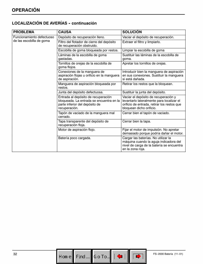
PROBLEMA CAUSA SOLUCIÓNFuncionamiento defectuosod l bill d
Depósito de recuperación lleno. Vaciar el depósito de recuperación.de las escobilla de goma Filtro del flotador de cierre del depósito
de recuperación obstruido.Extraer el filtro y limpiarlo.
Escobilla de goma bloqueada por restos. Limpiar la escobilla de gomaLáminas de la escobilla de gomagastadas.
Sustituir las láminas de la escobilla degoma.
Tornillos de orejas de la escobilla degoma flojos.
Apretar los tornillos de orejas.
Conexiones de la manguera deaspiración flojas u orificio en la manguerade aspiración.
Introducir bien la manguera de aspiraciónen sus conexiones. Sustituir la manguerasi está dañada.
Manguera de aspiración bloqueada porrestos.
Retirar los restos que la bloquean.
Junta del depósito defectuosa. Sustituir la junta del depósito.Entrada al depósito de recuperaciónbloqueada. La entrada se encuentra en laparte inferior del depósito derecuperación.
Vaciar el depósito de recuperación ylevantarlo lateralmente para localizar elorificio de entrada, retirar los restos quebloquean dicho orificio.
Tapón de vaciado de la manguera malcerrado.
Cerrar bien el tapón de vaciado.
Tapa transparente del depósito derecuperación floja.
Cerrar bien la tapa.
Motor de aspiración flojo. Fijar el motor de impulsión. No apretardemasiado porque podría dañar el motor.
Batería poco cargada. Cargar las baterías. No utilizar lamáquina cuando la aguja indicadora delnivel de carga de la batería se encuentraen la zona roja.

OPERACIÓN
33FS--2000 Batería (11--01)
ESPECIFICACIONES
MODELO FS--2000LONGITUD 1194 mm (47 in)
ANCHURA 559 mm (22 in)
ALTURA 965 mm (38 in)
PESO 146 Kg (315 lb)
CAPACIDAD DEL DEPÓSITO DE LA DISOLUCIÓN 38 L (10 gal)
CAPACIDAD DEL DEPÓSITO DE RECUPERACIÓN 45 L (12 gal)
ANCHURA DEL CARRIL DE LIMPIEZA 508 mm (20 in)
MOTOR DEL CEPILLO .75hp, 220 rpm, 24v, 20A, 560w
VACUUM MOTOR .5hp, 2 stage, 353w, 14A, 24v
ELEVACIÓN DEL AGUA 1118 mm (44 in)
BATERÍAS 2--130A/hr, 12v deep cycle
INDEPENDENCIA CON BATERÍAS TOTALMENTE CARGADAS 2.47 hours
LONGITUD DEL CABLE ELÉCTRICO 70dB(A)

ELECTRICAL DIAGRAMSDIAGRAMAS ELECTRICAS
FS-2000 Battery Scrubber (11--01)34
24V WIREDIAGRAM
BRUSHMOTOR
12VBATTER
Y
12VBATTER
Y35 AMPBREAKERSWITCH
VACUUMMOTOR
SAFETY LIGHTS
24VD.C.
FLASHER
CONDUIT
SOLENOID
CONDUIT
CHARGERPLUG
12 3
BRUSHSWITCH
BATTERY METER
VACUUMSWITCH
BLK 12
RED 12
BLK14
BLK
BLK
BLK10
RED 8
RED 10
RED 10
RED 18
RED 8
BLK 16
BLK18
RED 14
RED 8
BLK 16
RED 14
RED 10
RED 18
BLK18
BLK
BLK 18
RED 18RED 18
RED 14
RED
18
RED
16
BLK18

ELECTRICAL DIAGRAMSDIAGRAMAS ELECTRICAS
35FS-2000 Battery Scrubber (11--01)
12VBATTERY
12VBATTERY
CHARGERPLUG
SAFETY LIGHTS
BRUSHSWITCH
24VA.C.
FLA
SHER
VACUUMSWITCH
VACUUMMOTOR
BATTERY METER
BRUSHMOTOR
35 AMPBREAKERSWITCH
SOLENOID
12 3
RED
24V LADDERDIAGRAM

PARTS LISTLISTA DE PIEZAS
FS-2000 Battery Scrubber (11--01)36
REPLACEMENT BRUSHES AND PAD DRIVER GROUPCEPILLO DEL REEMPLAZO Y GRUPO DEL MANDO DE LA ALMOHADILLA
1
2
3
4
5

PARTS LISTLISTA DE PIEZAS
FS-2000 Battery Scrubber (11--01) 37
REPLACEMENT BRUSHES AND PAD DRIVER GROUPCEPILLO DEL REEMPLAZO Y GRUPO DEL MANDO DE LA ALMOHADILLA
REF PART # DESCRIPTION QTY.
∇ 1 240250 DBRUSH, POLY--SCRUB 1
240251 DBRUSH, DYNA--SCRUB 1
240252 DBRUSH, NYLON SCRUB/STRIP 1
240253 DBRUSH, STRATA SCRUB/STRIP 1
Y 2 240238 DLUGS, W/ SCREWS (SET OF 3) 3
∇ ASSEMBLY / CONJUNTO
Y INCLUDED IN ASSEMBLY / INCLUIDO EN EL CONJUNTO
D RECOMMENDED STOCK ITEMS / ARTICULOS RECOMENDADOS
REF PART # DESCRIPTION QTY.
∇ 3 240249 DPAD DRIVER ASM 20” 1
Y 4 240254 DLUGS, W/SCREWS (SET OF 3) 3
Y 5 25707 DLOCK, UNIVERSAL CENTER 1

PARTS LISTLISTA DE PIEZAS
FS-2000 Battery Scrubber (11--01)38
SOLUTION TANK GROUPGRUPE DEL DEPÓSITO DE DISOLUCIÓN
1
2
3
4
5
6
78
9
10
11
12
13
14 15
16
17
18
2021
19
22
2224
23
25
2728
29
2827
31
32
33
34
35
36
37
30 26
39
38
40
41

PARTS LISTLISTA DE PIEZAS
FS-2000 Battery Scrubber (10--04) 39
SOLUTION TANK GROUPGRUPE DEL DEPÓSITO DE DISOLUCIÓN
REF PART # DESCRIPTION QTY.
∇ 611633 ASM, COVER SOL. TANK BLUE 1
Y 1 603025 COVER, SOLUTION TANK BLUE 1
Y 2 611068 HINGE, COVER 1
Y 3 140706 RIVET, POP 1/8 7
4 606953 TANK, SOLUTION BLUE 1
5 607099 DSCREEN, SOLUTION FILL 1
6 3701.6 SCREW, #6 X 3/8 PAN SHTMTL 2
7 140032 WASHER, #6 FLAT 2
8 230665 BRACKET, CHARGER PLUG 1
9 140018 WASHER, #10 INT 2
10 140892 SCREW, 10--24 X 1/2 RNDPHL 2
11 2728.12 SCREW, 6--32 X 3/4 PANPHL 2
12 140019 WASHER, LOCK #6 EXT 2
13 605387 DCONNECTOR, RED 50AWO/CONT.
1
14 230925 SUPPORT, RECOVERY TANK 1
15 611418 SLEEVE, 0.437D 0.315B 0.146 1
16 140027 WASHER, 5/16 FLAT 2
17 140015 WASHER, SPLITLOCK 0.31 1
18 140226 SCREW, HEX .31--18 X 0.62 1
19 1012965 DCAP, PORT, SOLUTION FILL 1
20 01683 WASHER, FLAT #10 1
21 1018155 SCREW, PAN #10--12 X 0.62 1
∇ ASSEMBLY / CONJUNTO
Y INCLUDED IN ASSEMBLY / INCLUIDO EN EL CONJUNTO
D RECOMMENDED STOCK ITEMS / ARTICULOS RECOMENDADOS
REF PART # DESCRIPTION QTY.
22 14884 FITTING, BRS STR BM08/PM06 2
23 700420 ASM., HOSE W/SOL. INDICATOR 1
24 607776 CLAMP, HOSE 2WIRE BLK 1
25 609376 DECAL, FS--2000 SIDE 2
26 120101 DECAL, CASTEX LOGO 1
27 150419 FITTING, 1/4MX3/8H ELB 90 BRS 2
28 607775 CLAMP, HOSE 2WIRE BLK 2
29 606240 DHOSE, 3/8IDX5/8ODX10.25 1
30 605324 GASKET, 1/2” CLOSED CELL 2
31 602927 TRAY, BATTERY 1
32 120589 DECAL, BATTERY PLACEMENT 1
33 602592 SUPPORT, TUBE BATTERY 1
34 130364 DCABLE, BATTERY #6BLKX15” 1
35 140835 SCREW, 10--24X3/8 PAN PHL 2
36 612764 SHIELD, LIGHT 1
37 130023 LIGHT, SAFETY 24VDC 14” 1
38 130869 BATTERY, 12V 130AH (WET) 2
600594 BATTERY, 12V 130AH (DAMP) 2
39 603553 CHARGER, 24DC/12A 120V 1
130859 CHARGER, 24V 15AMP 230V/50HZ 1
40 700169 WIRE, #12X17 5/16 BLK 1
41 700168 WIRE, #12X12 3/8 RED 1

PARTS LISTLISTA DE PIEZAS
FS-2000 Battery Scrubber (10--04)40
SOLUTION TANK REAR PANEL GROUPCONJUNTO PANEL TRASERA
1
2
3
45
87
9
89
10
11
1314
12
87
9
6

PARTS LISTLISTA DE PIEZAS
FS-2000 Battery Scrubber (10--04) 41
SOLUTION TANK REAR PANEL GROUPCONJUNTO PANEL TRASERA
REF PART # DESCRIPTION QTY.
1 100151 DGASKET, TUBE ADAPTER 1
2 230664 ADAPTER, TUBE 1
3 140424 SPRING, TUBE--ADAPTER 1
4 1001210 BRACKET, TUBE MOUNTING 1
5 160617 DHOSE, VAC 1--1/2X24” W/CUFFS 1
6 230872 LATCH, PLATE BRUSH LIFT 1
7 140027 WASHER, 5/16 FLAT 3
8 140015 WASHER, 5/16 SPLITLOCK 4
D RECOMMENDED STOCK ITEMS / ARTICULOS RECOMENDADOS
REF PART # DESCRIPTION QTY.
9 140226 SCREW, 5/16--18X5/8 4
10 140548 NUT, 5/16 FINJAM 2
11 240191 KNOB ASSY, RND 1.00D .31--182.0L PLSTC
1
12 140259 SCREW, 1/4--20X5/8 2
13 140016 WASHER, LOCK .25 2
14 140000 WASHER, 1/4 FLAT 2

PARTS LISTLISTA DE PIEZAS
FS-2000 Battery Scrubber (10--04)42
RECOVERY TANK GROUPCONJUNTO DESPÓSITO RECUPERAR
1 5
2
3
4
6
9
12
11
10
13
14
15
16
1819
20
22
21
823
27
24
25
29
2831
30
32
33
3534
36 3334
35
2120
19
7
26
17

PARTS LISTLISTA DE PIEZAS
FS-2000 Battery Scrubber (10--04) 43
RECOVERY TANK GROUPCONJUNTO DESPÓSITO RECUPERAR
REF PART # DESCRIPTION QTY.
∇ 1 701103 ASM, STANDPIPE W/NIPPLE 1
Y 2 606088 FITTING, 1--1/2” NIPPLE 1
3 101714 DGASKET, WASTE AIR CHAMBER 1
4 210240 NUT, 1--1/2 FPT FLNG METAL 1
5 180613 DFLOAT, SHUT--OFF (1) BALL 1
∇ 6 614148 ASM., TANK REC. BLUE 1
Y 7 613287 LABEL, WARNING DC 6” X 2.25” 1
Y 8 120588 DECAL, BATTERY RECHARGING 1
∇ 9 100102 DASM., LID CLEAR W/STND HOLE 1
Y 10 100109 DLID, OUTER RING ONLY 1
Y 11 100105 DLID, CLEAR CENTER ONLY 1
12 140826 SCREW, #6 X 3/4 PHL SHTMTL 7
13 3701.6 SCREW, #6 X 3/8 PHL SHTMTL 1
14 230513 CHAIN 1
∇ 15 1010143 DASM., DRAIN HOSE 1
Y 16 1008639 DASM., CAP, DRAIN HOSE 1
Y 17 1008637 DO--RING 1
18 140308 CLAMP, HOSE 1
∇ ASSEMBLY / CONJUNTO
Y INCLUDED IN ASSEMBLY / INCLUIDO EN EL CONJUNTO
D RECOMMENDED STOCK ITEMS / ARTICULOS RECOMENDADOS
REF PART # DESCRIPTION QTY.
19 140259 SCREW, 1/4--20X5/8 2
20 140016 WASHER, 1/4 LOCK 2
21 140000 WASHER, 1/4 FLAT 2
22 140960 DCABLE, REC. TANK SUPPORT 1
23 606923 STUD, 1/4--20 X 4.00 3
24 100038 DGASKET VAC MOTOR 5.7 1
∇ 25 605357 DMOTOR, VAC 24V 1/2 HP 1
Y 26 190163 DBRUSH, CARBON 2/PK 2
27 130133 TERMINAL, MALE .25 2
28 600009 DMUFFLER, VAC EXHAUST 1
29 130041 WIRE TIE, 11--1/2X.19 NY 1
30 41169 NUT, HEX LOCK .25--20 NY 3
31 140000 WASHER, 1/4 FLAT 3
32 605244 DHINGE, RECOVERY TANK 1
33 140000 WASHER, 1/4 FLAT 9
34 140052 WASHER, LOCK EXT 0.25 9
35 140885 SCREW, TRS 1/4--20 X 0.50 PHL 9
36 140300 CLAMP, INSULATED 1/2”ID 1

PARTS LISTLISTA DE PIEZAS
FS-2000 Battery Scrubber (10--04)44
CONTROL CONSOLE GROUPCONJUNTO CONSOLA DE CONTROLES
2
1
3
2
4
56 7
8 9
10
1112
13
14
16
17
18
1920211
22
23
24
25
24
26
29
28
27
29
30
31
32
15

PARTS LISTLISTA DE PIEZAS
FS-2000 Battery Scrubber (10--04) 45
CONTROL CONSOLE GROUPCONJUNTO CONSOLA DE CONTROLES
REF PART # DESCRIPTION QTY.
1 200823 GRIP, HANDLE TUBE 2
2 608605 DSWITCH, ROCKER DPST SEAL 2
3 606020 DMETER, BATTERY VOLTAGE 24V 1
4 600641 DECAL, DASH 1
5 606948 CONTROL, CONSOLE BLUE 1
6 230709 HANDLE, TUBE 1
7 230744 BRACKET, ELECTRONICS MOUNT 1
8 606243 TAPE, ACRYLIC FOAM, 1”WX12L 1
9 130021 DFLASHER, 24VDC 1
10 130756 DBREAKER, CIRCUIT 35A 1
11 610949 COVER, CONTROL CONSOLE 1
12 140018 WASHER, LOCK #10 INT 2
13 140197 SCREW, TRS 10--24X0.38 PHL SEM 2
14 606105 LABEL, HZRD DO NOT SPRAY 1
15 605840 LOOM, 3/4DIA X 2.5’ 1
16 281001009 DTERMINAL, RING #10 2
D RECOMMENDED STOCK ITEMS / ARTICULOS RECOMENDADOS
REF PART # DESCRIPTION QTY.
17 606404 DASM., DIODE W/RING TRMNLS 1
18 140519 NUT, 10--24 KEP 2
19 605905 DSOLENOID, 24 VDC 125A 1
20 140900 SCREW, 10--24X3/4 1
21 140916 CLAMP, CABLE 5/8ID 1
22 230715 TUBE, HANDLE ADJUSTMENT 1
23 230649 PIN, HANDLE ADJUSTMENT 2
24 230710 PIN, HANDLE LOCK 2
25 140415 SPRING, LOCK PIN 1
26 140241 BOLT, SHOULDER 5/8 X 2 2
27 700167 HARNESS, WIRE 1
28 140900 SCREW, 10--24X1 2
29 614517 CLAMP HOSE 3/4 TO 1--3/4 2
30 140018 WASHER, INT. 2
31 605823 DO--RING .926 ID X .99600 2
32 609969 DPLUG, HOUR METER 2

PARTS LISTLISTA DE PIEZAS
FS-2000 Battery Scrubber (10--04)46
LEVER GROUPCONJUNTO DE PALANCAS
20
1
7
98
2
4
7815
3
10
5
11
112541
26
24
34
2835
31
30
37
42
2928
33
6
12
14
19
7
8
9
1
57
16
11
13
158
3
8
1718
11
12
13
42
39
27
32
32
36
38
40
16 2122
23

PARTS LISTLISTA DE PIEZAS
FS-2000 Battery Scrubber (10--04) 47
LEVER GROUPCONJUNTO DE PALANCAS
REF PART # DESCRIPTION QTY.
1 230661 PLATE, LOCK CONTROL HOUSING 2
2 611979 WELDMENT, DRAIN HOSEHANGER
1
3 200816 DGRIP, HANDLE 2
4 230719 HANDLE, SOLUTION VALVE 1
5 230735 BUSHING, SPACER 2
6 140060 WASHER, .505 X .750 X .045 WAVE 1
7 140027 WASHER, 5/16 FLAT 4
8 140015 WASHER, 5/16 SPLITLOCK 4
9 140226 SCREW, 5/16--18X5/8 2
10 32520 NUT, .25--20 HEXJAM 1
11 140000 WASHER, 1/4 FLAT 4
12 140134 SLEEVE, 0.376D 0.253B 0.28L 2
13 140208 SCREW, HEX .25--20 X 1.00 2
14 230728 HANDLE, SQUEEGEE LIFT 1
15 140221 SCREW, HEX .31--18X1.25 2
16 140016 WASHER, 1/4 LCK 2
17 140259 SCREW, 1/4--20X5/8 1
18 140510 NUT, 1/4--20 HEXJAM 1
19 1015636 DCABLE, SQUEEGEE LIFT 1
20 230718 LEVER, SOLUTION VALVE 1
21 140951 SCREW, 10--24X7/16 2
D RECOMMENDED STOCK ITEMS / ARTICULOS RECOMENDADOS
REF PART # DESCRIPTION QTY.
22 140018 WASHER, LOCK INT #10 2
23 230712 PLATE, SQUEEGEE LOCK 1
24 140616 PIN, ROLL 1
25 230657 ARM, VALVE 1
26 606238 HOSE, 3/8IDX5/8ODX18 1
27 607776 CLAMP, HOSE 2WIRE BLK 1
28 140011 WASHER, 3/16 FLAT 4
29 140552 NUT, 10--24 NYLOCK 2
30 210259 DVALVE, BALL 3--WAY 1
31 140259 SCREW, HEX .25--20 X .62 2
32 27048 FITTING, BRS E90 04PM/04PF 2
33 140016 WASHER, 1/4 LOCK 2
34 600750 BRACKET, VALVE 1
35 140895 SCREW, 10--24X3/4 2
36 150206 FITTING, BRS PLUG 04PM HEX 1
37 605394 FITTING, BRS E45 BM06/PM04 1
38 150517 FITTING, BRS STR 04PM/08BM 1
39 606241 HOSE, 1/2ID X 6” 1
40 180629 FILTER, SCREEN 012 MESH 1
41 41169 NUT, HEX LOCK .25--20 NL 1
42 607775 CLAMP, HOSE 2WIRE BLK 2

PARTS LISTLISTA DE PIEZAS
FS-2000 Battery Scrubber (11--01)48
NON-DRIVE MODEL WHEEL GROUPCONJUNTO PARA LEVANTAR CEPILLO
9
1
2
3
4
56
57
8
510
56
11
8
13
12
1415
16
17
18
1920
2122
25
24
47
56
23
4
58
2627
28
26

PARTS LISTLISTA DE PIEZAS
FS-2000 Battery Scrubber (10--04) 49
NON-DRIVE MODEL WHEEL GROUPCONJUNTO PARA LEVANTAR CEPILLO
REF PART # DESCRIPTION QTY.
1 230874 LEVER, BRUSH LIFT FOOT 1
2 200816 GRIP, HANDLE 1
3 102560 PAD, NON--SLIP 1.62 SQ. 2
4 140509 NUT, 1/2--13 HEXJAM 4
5 140045 WASHER, .510X1.25X.06 FLAT 10
6 140139 SLEEVE, 0.625D 0.50B 0.25L STL 6
7 140024 WASHER, 1/2 LOCK 3
8 140236 SCREW, .50--13 X 1.25 5
9 230870 WELDMENT, LIFT BRACKET 1
10 02931 NUT, HEX .50--13 LOCK NY 2
11 230869 BRACKET, AXLE & SQ PIVOT MNT 2
12 140024 WASHER, LOCK 0.50 4
13 140237 SCREW, HEX .50--13 X 1.00 6
14 140045 WASHER, .510X1.25X.06 FLAT 2
D RECOMMENDED STOCK ITEMS / ARTICULOS RECOMENDADOS
REF PART # DESCRIPTION QTY.
15 02991 SCREW, HEX .31--18 X 0.75 2
16 140433 SPRING, EXT .50 X 3.00 2
17 140506 NUT, 5/16--18 HEX 2
18 02994 SCREW, HEX .38--16 X 0.75 2
19 140017 WASHER, LOCK SPLIT 0.38 2
20 140028 WASHER, FLAT .38 2
21 1012022 DWHEEL 8”X1.5” 2
22 230743 SHAFT, AXLE .75D 166L 1
23 140234 SCREW, 1/2--13X2--1/2 HXHDCP 1
24 3148.816 WASHER, 0.52B 0.88D .06 1
25 140430 SPRING, HANDLE LOCK 1
26 140127 BEARING, THRUST 2
27 230871 BRACKET, MOTOR MOUNT 1
28 130040 WIRE TIE, NYLON 1

PARTS LISTLISTA DE PIEZAS
FS-2000 Battery Scrubber (11--01)50
BRUSH DRIVE GROUPCONJUNTO IMPULSO DE CEPILLO
1
2
3
4
5
6
7
89
10
11
1213
14
15
16
17
18
19
2423
2827
26
27
21
23
22
20
2425

PARTS LISTLISTA DE PIEZAS
FS-2000 Battery Scrubber (10--04) 51
BRUSH DRIVE GROUPCONJUNTO IMPULSO DE CEPILLO
REF PART # DESCRIPTION QTY.
∇ 1 130491 DMOTOR, W/GEARBOX 24V IMP 1
Y 190970 DBRUSH, CARBON (SET OF 4) 4
Y 190741 DASM, BRUSH CARD 1
Y 630609 DGEAR BOX, IMPERIAL MOTOR 1
2 130192 TERMINAL ENDS 2
3 140431 SPRING, EXT 1.0 X 5.00 X 0.95 1
4 230871 BRACKET, MOTOR MOUNT 1
5 140823 SCREW, TRS 10--24 X 0.63 PHL 1
6 100091 BUMPER, RECESSED 1
7 140552 NUT, HEX 10--24 NY 1
8 607775 CLAMP, HOSE 2WIRE BLK 1
9 609924 HOSE, 3/8IDX5/8ODX19” CLEAR 1
10 140017 WASHER, LOCK SPLIT 0.38 4
11 140202 SCREW, HEX .31--16 X 1.00 4
12 606335 PLATE, DRIVE MOLDED 1
13 140197 SCREW, TRS 10--24X0.38 PHLSEM 4
∇ ASSEMBLY / CONJUNTO
Y INCLUDED IN ASSEMBLY / INCLUIDO EN EL CONJUNTO
D RECOMMENDED STOCK ITEMS / ARTICULOS RECOMENDADOS
REF PART # DESCRIPTION QTY.
14 230697 DSTOP, DRIVER RELEASE 1
15 230651 DCLAMP, BRUSH PLATE 1
16 140417 DCLIP, SPRING 1
17 25732 WASHER, 0.36B 1.25D .093 FLT 2
18 140015 WASHER, LOCK SPLIT 0.31 1
19 140219 SCREW, HEX .31--18 X 1.00 1
20 140234 SCREW, HEX .50--13 X 2.50 1
21 3148.816 WASHER, 0.52B 0.88D .06 1
22 140430 SPRING, HANDLE LOCK 1
23 140127 BEARING, THURST 2
24 140509 NUT, 1/2--13 HXJM 3
25 140024 WASHER, LOCK 0.50 2
26 140139 SLEEVE, 0.625D 0.500B 0.25L 2
27 140045 WASHER, .51BX1.25DX.06 FLAT 4
28 140236 SCREW, HEX .50--13 X 1.25 2

PARTS LISTLISTA DE PIEZAS
FS-2000 Battery Scrubber (11--01)52
SKIRT GROUPCONJUNTO JUEGO
1
8
7
6
2
17
16
15
14
3
4
9
8
7
9
10
5
13
12
11

PARTS LISTLISTA DE PIEZAS
FS-2000 Battery Scrubber (10--04) 53
SKIRT GROUPCONJUNTO JUEGO
REF PART # DESCRIPTION QTY.
∇ 606989 ASM, SKIRT 20” BLUE 1
Y 1 140799 DSCREW, TRS .31--18 X 1.50 PHL 2
Y 2 1014918 DWHEEL, RBR 3”X1” W/BUSHINGS 2
Y 3 140015 WASHER, 5/16 SPLITLOCK 4
Y 4 140027 WASHER, 5/16 FLAT 2
Y 5 230875 WEIGHT, 2X2.5X9.5 1
Y 6 609457 SKIRT, HSG. 20” BLUE 1
Y 7 605958 DGUARD, SPLASH 2
Y 8 605959 STRAP, SPLASH GUARD 2
∇ ASSEMBLY / CONJUNTO
Y INCLUDED IN ASSEMBLY / INCLUIDO EN EL CONJUNTO
D RECOMMENDED STOCK ITEMS / ARTICULOS RECOMENDADOS
REF PART # DESCRIPTION QTY.
Y 9 605975 SCREW, TRS 10--24X0.50 PHL SEM 16
Y 10 606986 DCASTER, SWIVEL 3”X1.25” 2
Y 11 140000 WASHER, 1/4 FLAT 8
Y 12 140016 WASHER, LOCK 0.25 8
Y 13 140259 SCREW, HEX .25--20 X .62 8
Y 14 140220 SCREW, 5/16--18X2--1/2 TAP 2
15 140027 WASHER, FLAT 0.31 4
16 140015 WASHER, LOCK SPLT 0.31 4
17 140216 SCREW, HEX .31--18 X 1.50 4
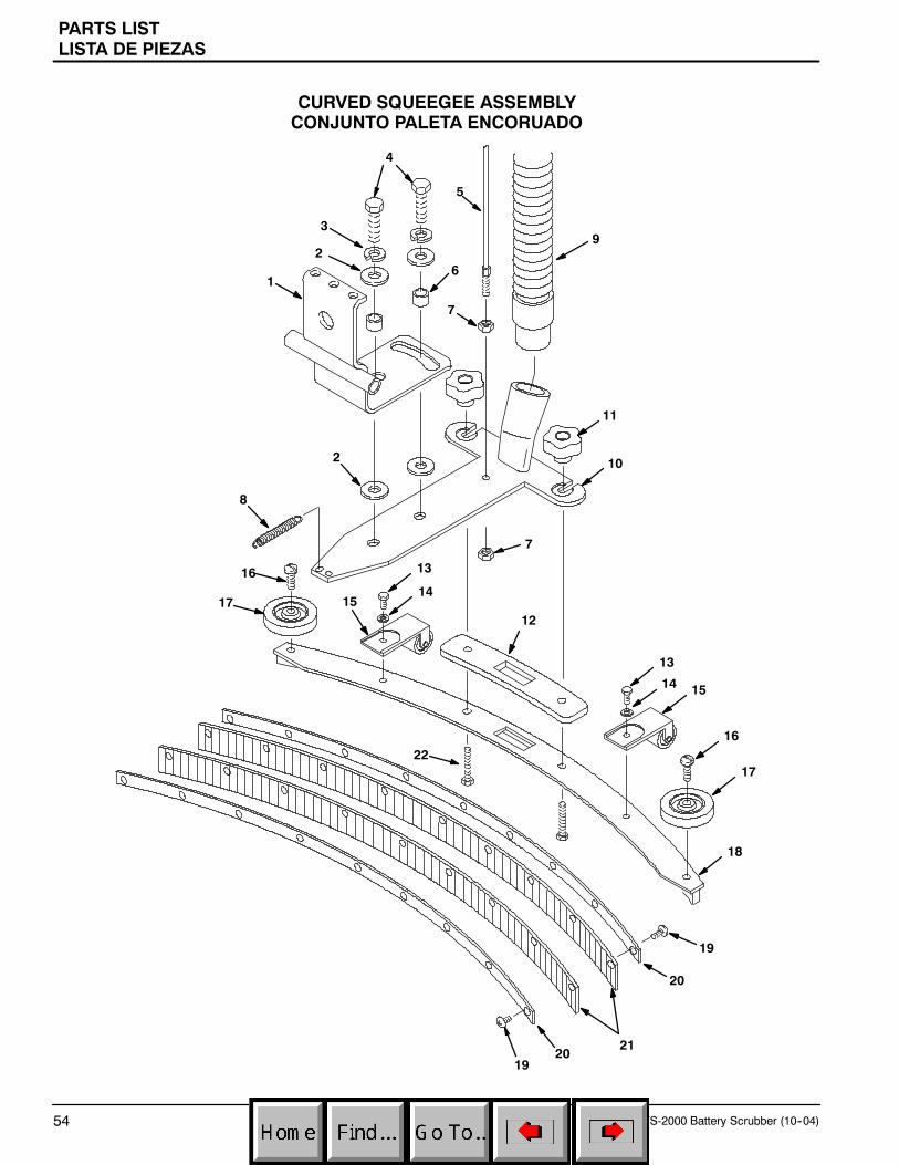
PARTS LISTLISTA DE PIEZAS
FS-2000 Battery Scrubber (10--04)54
CURVED SQUEEGEE ASSEMBLYCONJUNTO PALETA ENCORUADO
9
7
5
4
3
26
1
2 10
7
11
8
17
16
12
22
19
15
17
16
14
13
18
13
1415
21
20
2019

PARTS LISTLISTA DE PIEZAS
FS-2000 Battery Scrubber (10--04) 55
CURVED SQUEEGEE ASSEMBLYCONJUNTO PALETA ENCORUADO
REF PART # DESCRIPTION QTY.
1 230731 PIVOT, SQUEEGEE MOUNT 1
2 140045 WASHER, 0.51B 1.25D .06 FLAT 4
3 140024 WASHER, LOCK 0.50 2
4 140237 SCREW, HEX .50--13 X 1.00 2
5 1015636 DCABLE, SQUEEGEE LIFT 1
6 140139 SLEEVE, 0.625D 0.50B 0.25L 2
7 140524 NUT, 1/4--20 KEP 2
8 140433 SPRING, EXT .50 X 3.00 2
9 160617 DHOSE, VAC 1 1/2X24” W/CUFFS 1
10 230730.BK BRACKET, SQUEEGEE MOUNT 1
∇ 603261 DASM., SQUEEGEE CURVED 1
Y 11 1011094 DKNOB, RND 1.50 DIA 5 EAR 2
Y 12 603260 DGASKET, SQUEEGEE CURVED 1
Y 13 140226 SCREW, HEX .31--18 X 0.62 2
Y 14 140015 WASHER, LOCK SPLIT 0.31 2
∇ ASSEMBLY
Y INCLUDED IN ASSEMBLY
D RECOMMENDED STOCK ITEMS
REF PART # DESCRIPTION QTY.
Y 15 700844 DASM, SQUEEGEE ROLLER 2
Y 16 140799 SCREW, TRS .31--18 X 1.50 2
Y 17 1014918 DWHEEL, RBR 3”X1” W/BUSHINGS 2
Y 18 602959 WELDMENT, SQUEEGEE 20” 1
Y 19 605975 SCREW, TRS 10--24X.50 PHL SEM 18
Y 20 602964 DPLATE, SQUEEGEE RETAINING 2
Y 21 603659 DBLADE, URETHANE (STANDARD) 2
Y 22 140221 SCREW, HEX .31--18 X 1.25 2
∇ 611453 DKIT, SQUEEGEE LINATEX(OPTIONAL)
1
Y 607465 DBLADE, LINATEX REAR ONLY(OPTIONAL)
1
Y 611449 DBLADE, LINATEX FRONT ONLY(OPTIONAL)
1
606676 DBLADE, GUM RUBBER REARONLY (OPTIONAL)
1

OPTIONSOPCIONES
56 FS-2000 Battery Scrubber (11--01)
ESr KITESr JUEGO
1
23
45
6
7
8 89
10
11
12
13
14
15
16
14
17
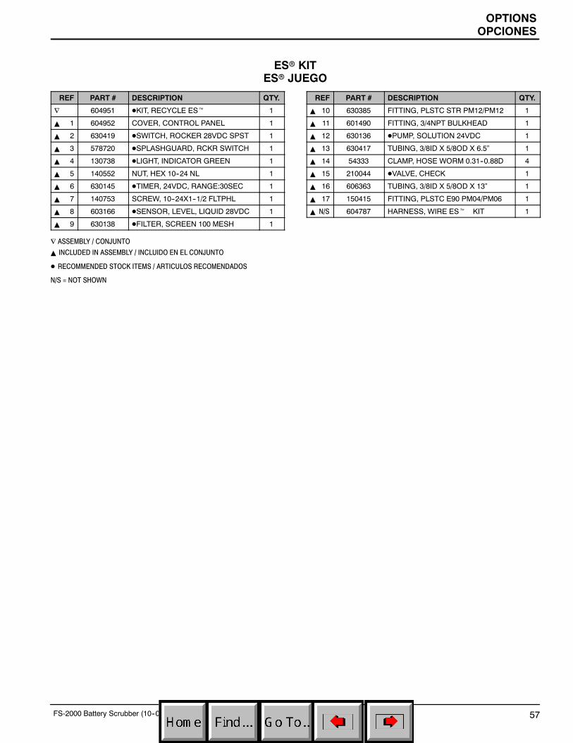
OPTIONSOPCIONES
57FS-2000 Battery Scrubber (10--04)
ESr KITESr JUEGO
REF PART # DESCRIPTION QTY.
∇ 604951 DKIT, RECYCLE ESt 1
Y 1 604952 COVER, CONTROL PANEL 1
Y 2 630419 DSWITCH, ROCKER 28VDC SPST 1
Y 3 578720 DSPLASHGUARD, RCKR SWITCH 1
Y 4 130738 DLIGHT, INDICATOR GREEN 1
Y 5 140552 NUT, HEX 10--24 NL 1
Y 6 630145 DTIMER, 24VDC, RANGE:30SEC 1
Y 7 140753 SCREW, 10--24X1--1/2 FLTPHL 1
Y 8 603166 DSENSOR, LEVEL, LIQUID 28VDC 1
Y 9 630138 DFILTER, SCREEN 100 MESH 1
∇ ASSEMBLY / CONJUNTO
Y INCLUDED IN ASSEMBLY / INCLUIDO EN EL CONJUNTO
D RECOMMENDED STOCK ITEMS / ARTICULOS RECOMENDADOS
N/S = NOT SHOWN
REF PART # DESCRIPTION QTY.
Y 10 630385 FITTING, PLSTC STR PM12/PM12 1
Y 11 601490 FITTING, 3/4NPT BULKHEAD 1
Y 12 630136 DPUMP, SOLUTION 24VDC 1
Y 13 630417 TUBING, 3/8ID X 5/8OD X 6.5” 1
Y 14 54333 CLAMP, HOSE WORM 0.31--0.88D 4
Y 15 210044 DVALVE, CHECK 1
Y 16 606363 TUBING, 3/8ID X 5/8OD X 13” 1
Y 17 150415 FITTING, PLSTC E90 PM04/PM06 1
Y N/S 604787 HARNESS, WIRE ESt KIT 1

OPTIONSOPCIONES
58 FS-2000 Battery Scrubber (11--01)
SQUEEGEE WAND ASSEMBLYGROUPE D’ASPIRATION ET RACLETTE À MAIN
1
2
3
4
REF PART # DESCRIPTION QTY.
∇ 190928 DASM, WAND DOUBLE BEND 1
Y 1 6108.1 WAND, DOUBLE BEND 1
Y 2 13840 SQUEEGEE ASM PUSH/PULL 1
∇ ASSEMBLY / CONJUNTO
Y INCLUDED IN ASSEMBLY / INCLUIDO EN EL CONJUNTO
D RECOMMENDED STOCK ITEMS / ARTICULOS RECOMENDADOS
REF PART # DESCRIPTION QTY.
Y 3 160481 DHOSE, VAC 1--1/2X10’ 1
Y 4 160451 CONNECTOR, VAC HOSE 1
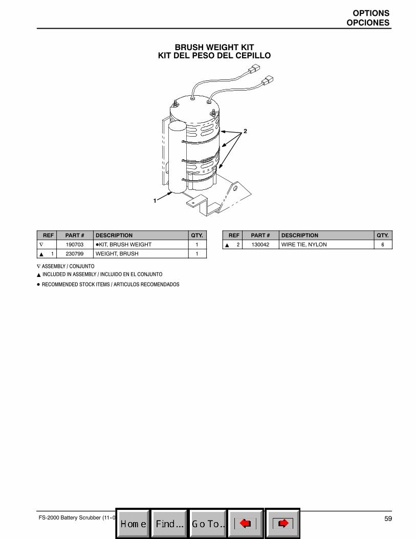
OPTIONSOPCIONES
59FS-2000 Battery Scrubber (11--01)
BRUSH WEIGHT KITKIT DEL PESO DEL CEPILLO
1
2
REF PART # DESCRIPTION QTY.
∇ 190703 DKIT, BRUSH WEIGHT 1
Y 1 230799 WEIGHT, BRUSH 1
∇ ASSEMBLY / CONJUNTO
Y INCLUDED IN ASSEMBLY / INCLUIDO EN EL CONJUNTO
D RECOMMENDED STOCK ITEMS / ARTICULOS RECOMENDADOS
REF PART # DESCRIPTION QTY.
Y 2 130042 WIRE TIE, NYLON 6