Embed Size (px)
Citation preview
Cary 100/300
Certification Manual
For Cary 100/300 UV-Vis Spectrophotometers
85 101747 00 October 2002
Review
Copy
Cary 100/300 certification manual
ii Publication date: 10/02
Varian offices Varian has offices in most countries. The major offices for optical spectroscopy products are listed below: Varian Australia Pty Ltd (Manufacturing site) 679 Springvale Road Mulgrave, Victoria 3170 Australia International telephone: + 61 3 9560 7133 International fax: + 61 3 9560 7950 Varian Instruments 2700 Mitchell Dr. Walnut Creek, CA 94598 USA Phone: 1 800 926 3000 International telephone: +1 925 939 2400 International fax: +1.925.945.2102 Varian BV Herculesweg 8, 4338 PL, Middelburg, Netherlands International telephone: +31 118 67 1000 International Fax: +31 118 62 3193
Internet
The Varian Internet home page can be found at:
http://www.varianinc.com
Varian Australia Pty Ltd is the owner of copyright on this document and any associated software. Under law, the written permission of Varian Australia Pty Ltd must be obtained before either the documentation or the software is copied, reproduced, translated or converted to electronic or other machine-readable form, in whole, or in part.
First published May 1999 in Australia. Revised in October 2002. Comments about this manual should be directed to Varian Australia at the address above or by e-mail to [email protected].
Varian Australia is ISO9001 certified.
© 1999 Varian Australia Pty Ltd (A.C.N. 004 559 540) All rights reserved.
® Windows 95, 98, 2000, NT4 and XP are registered trademarks of Microsoft Corp.
Review
Copy
Cary 100/300 certification manual
Publication date: 10/02 iii
Contents
1. Introduction..............................................................................1-1
1.1 Cary certification program 1-2
1.2 Available tests 1-2
1.3 Cary performance tests 1-3
2. Test kits and equipment...........................................................2-1
2.1 Test kits 2-1
2.2 Other test equipment 2-2
3. Instrument tests........................................................................3-1
3.1 Using the Cary WinUV Validate application software 3-1
4. Instrument performance tests..................................................4-1
4.1 Wavelength accuracy 4-1
4.2 Wavelength reproducibility 4-2
4.3 Baseline flatness 4-3
4.4 Photometric noise 4-4
5. European Pharmacopoeia tests ................................................5-1
5.1 Control of wavelengths 5-1
5.2 Control of absorbance 5-3
5.3 Resolution power 5-4
5.4 Stray light 5-5
6. US Pharmacopoeia tests ...........................................................6-1
6.1 Wavelength accuracy 6-1
6.2 Photometric accuracy 6-3
7. Australian TGA tests ................................................................7-1
7.1 Wavelength accuracy 7-1
7.2 Resolution power 7-4
7.3 Baseline flatness 7-5
7.4 Stray light 7-6
7.5 Photometric accuracy 7-8
8. Other instrument tests .............................................................8-1
8.1 Resolution power 8-1
8.2 Stray light 8-2
8.3 Photometric accuracy 8-3
8.4 Photometric linearity 8-4
8.5 Photometric stability 8-5
8.6 Photometric noise 8-6
Review
Copy
Cary 100/300 certification manual
iv Publication date: 10/02
9. Accessory tests .........................................................................9-1
9.1 VW absolute specular reflectance accessory test 9-5
9.2 Diffuse reflectance accessory tests 9-1
10. Care and handling..................................................................10-1
10.1 General care 10-1
10.2 Cleaning the liquid standards 10-1
10.3 Re-calibrating the liquid standards 10-2
10.4 Ordering NIST reference materials 10-3
10.5 Re-calibrating the NIST Filter standards 10-3
10.6 Cleaning the diffuse reflectance standards 10-4
10.7 Re-calibrating the diffuse reflectance standards 10-4
11. Certification kit log sheet.......................................................11-1
Review
Copy
Cary 100/300 certification manual
Publication date: 10/02 1-1
1. Introduction
The Cary 100/300 Certification Manual can be used in conjunction with the Cary 100/300 Validation Binder 2 to qualify your Cary instrument and accessories. Varian can provide an Installation and Operational Qualification service and provide ongoing operational testing throughout the life of the instrument.
This manual assists you to run operational checks on the instrument and the accessories. You can run these tests to verify that the instrument is performing to the specifications required. Certification of instrument analytical methods is not included.
This validation package is suitable for use with Cary 100/300 series instruments running Cary WinUV Version 2.0 or Cary WinUV Pharma Version 2.5 software.
A Cary 1/3 series instrument is regarded as being the same as a Cary 100/300 series instrument when it has Version 8.0 (or higher) firmware installed and is run using Cary WinUV software.
Throughout this document (except where explicitly stated otherwise) all references to "Cary system" and "Cary instruments" shall be taken to include the Cary 1, Cary 3, Cary 100 and Cary 300 systems. Also, other than in Binder 1, Section 3, a reference to Cary 100 will be taken to include Cary 1, and Cary 300 to include Cary 3.
The various module names within each of the Cary 1, 3, 100 and 300 series (e.g. Cary 1E, Cary 3G, Cary 100 Bio, Cary 300 Conc) reflect the software applications and accessories shipped with the instrument.
Varian services The following services are available from Varian:
• Fully qualified Varian-trained personnel to perform instrument testing.
• Fully documented instrument test results to fulfill your auditing requirements.
• Instrument certification services that can be added to your existing Varian Support Agreement.
• Standards used in instrument certification that are either primary standards or are traceable back to recognized Standards Institutes such as the U.S. National Institute for Standard and Technology, NIST
Contact your local Varian office for full details.
Review
Copy
Cary 100/300 certification manual
1-2 Publication date: 10/02
1.1 Cary certification program Good Laboratory Practices, quality control methods and other regulatory requirements mandate proof of performance from your Cary system. The following procedures are designed to help you meet those needs. A spectrophotometer must meet several criteria to demonstrate that it is operating correctly. The Cary 100/300 Certification Manual outlines the tests and results expected from the instrument, including wavelength accuracy, wavelength reproducibility, baseline flatness, photometric noise, stray light, photometric linearity, and photometric accuracy. These tests are automated using the Cary WinUV Validate application software to improve the measurement, calculation and reporting of these results.
The instruments published guaranteed specifications are used throughout this document. An instrument will age and its performance may change over time. The absolute amount of the change is of less importance than the rate of change. It is more important to track the instrument’s performance during its life to establish confidence in analytical results. As an instrument ages, performance may be improved by additional instrument service, such as cleaning of the optics, but it may not have any effect on improving the overall analysis. Ultimately, the instruments operator will need to determine what level of instrument performance is required for his/her analysis. This will then determine what out-of-specification parameters, if any, require additional service to meet the specification.
1.2 Available tests Regulatory authorities demand that generated analytical data complies with Good Laboratory Practices (GLP). A range of performance tests for UV-Visible spectrophotometers are specified by the British/European Pharmacopoeia (BP/EP) and the US Pharmacopoeia (USP). These tests are included in this manual.
Also included in this manual are a series of tests that were originally performed at manufacture. These tests are designed to check that all components of the spectrophotometer are working correctly and within the specifications set by Varian. These tests are a minimum set of criteria for a general purpose UV-Vis spectrophotometer.
Performance tests should be performed routinely or whenever the instrument has been disturbed or serviced, or when malfunctioning is suspected. The frequency of routine testing should be determined based on the type of application and the frequency of use of the instrument.
The table on the opposite page summarizes the tests available in the Cary WinUV software listed by the pharmacopoeia requirements. (e.g. EP, USP and TGA).
✒ Note: The Cary WinUV Validate application software includes the "Australian Code of GMP for Therapeutic Goods (TGA), Guidelines for Laboratory Instrumentation TGA" tests.
On 1 January 1999, the following change to the Manufacturing Principles of the Therapeutic Goods Act 1989 took effect:
Part 2 of the Australian Code of GMP for Medicinal Products was replaced with Annex 1 of the EU Guide to GMP.
The Cary WinUV software still reflects the tests, which were recommended by the TGA prior to 1 January 1999.
Review
Copy
Cary 100/300 certification manual
Publication date: 10/02 1-3
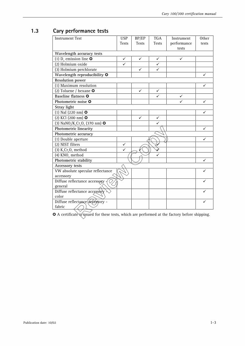
1.3 Cary performance tests Instrument Test USP
Tests BP/EP Tests
TGA Tests
Instrument performance
tests
Other tests
Wavelength accuracy tests (1) D2 emission line ✪ � � � � (2) Holmium oxide � � (3) Holmium perchlorate � � Wavelength reproducibility ✪ � Resolution power (1) Maximum resolution � (2) Toluene / hexane ✪ � � Baseline flatness ✪ � � Photometric noise ✪ � � Stray light (1) NaI (220 nm) ✪ � (2) KCl (200 nm) ✪ � � (3) NaNO//K2Cr2O7 (370 nm) ✪ � Photometric linearity � Photometric accuracy (1) Double aperture � (2) NIST filters � � (3) K2Cr2O7 method � � � (4) KNO3 method � Photometric stability � Accessory tests VW absolute specular reflectance accessory
�
Diffuse reflectance accessory - general
�
Diffuse reflectance accessory - color
�
Diffuse reflectance accessory - fabric
�
✪ A certificate is issued for these tests, which are performed at the factory before shipping. Review
Copy

Cary 100/300 certification manual
1-4 Publication date: 10/02
This page is intentionally left blank
Review
Copy
Cary 100/300 certification manual
Publication date: 10/02 2-1
2. Test kits and equipment
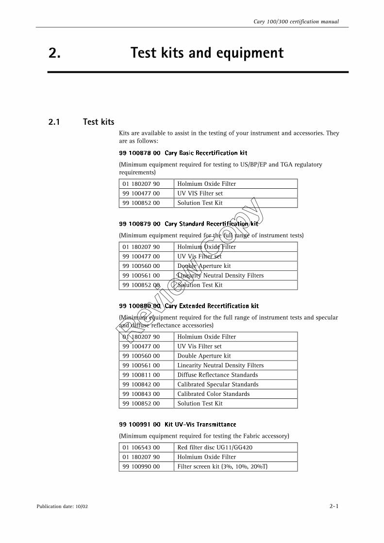
2.1 Test kits Kits are available to assist in the testing of your instrument and accessories. They are as follows:
��������������$BSZ�#BTJD�3FDFSUJGJDBUJPO�LJU��
(Minimum equipment required for testing to US/BP/EP and TGA regulatory requirements)
01 180207 90 Holmium Oxide Filter 99 100477 00 UV VIS Filter set 99 100852 00 Solution Test Kit
��������������$BSZ�4UBOEBSE�3FDFSUJGJDBUJPO�LJU�
(Minimum equipment required for the full range of instrument tests)
01 180207 90 Holmium Oxide Filter 99 100477 00 UV Vis Filter set 99 100560 00 Double Aperture kit 99 100561 00 Linearity Neutral Density Filters 99 100852 00 Solution Test Kit
��������������$BSZ�&YUFOEFE�3FDFSUJGJDBUJPO�LJU��
(Minimum equipment required for the full range of instrument tests and specular and diffuse reflectance accessories)
01 180207 90 Holmium Oxide Filter 99 100477 00 UV Vis Filter set 99 100560 00 Double Aperture kit 99 100561 00 Linearity Neutral Density Filters 99 100811 00 Diffuse Reflectance Standards 99 100842 00 Calibrated Specular Standards 99 100843 00 Calibrated Color Standards 99 100852 00 Solution Test Kit
��������������,JU�67�7JT�5SBOTNJUUBODF��
(Minimum equipment required for testing the Fabric accessory)
01 106543 00 Red filter disc UG11/GG420 01 180207 90 Holmium Oxide Filter 99 100990 00 Filter screen kit (3%, 10%, 20%T)
Review
Copy
Cary 100/300 certification manual
2-2 Publication date: 10/02
2.2 Other test equipment
2.2.1 NIST 930E Filters These filters are required for measuring the photometric accuracy of the instrument according to the USP and TGA regulatory authorities. The filters can only be purchased directly from the National Institute of Standards and Technology (NIST) Standard Reference Materials.
Contact details for NIST can be found in section 10.4 of this manual.
2.2.2 Calibrated Precision Thermometer A calibrated precision thermometer is required to accurately determine the temperature accuracy for the Varian thermostatted accessories. The absolute accuracy of this thermometer is to be determined by the intended use of the accessory, but it is suggested that a thermometer with an absolute accuracy of ±0.1oC be used.
2.2.3 Calibrated linear measuring device A calibrated vernier or other similar measuring device capable of measuring up to 100 mm with an accuracy of ±0.1 mm is required to test the positional accuracy of the Varian sample transport accessory.
Review
Copy
Cary 100/300 certification manual
Publication date: 10/02 3-1
3. Instrument tests
Varian establishes the performance factors and specifications for each instrument. There is a precise procedure for determining whether each factor meets the specification. The following sections of this document detail the tests that characterize instrument performance along with the Varian specifications and instrument parameter information.
✒ Note: Specifications are subject to change without notice. Please refer to the latest issue of “Cary UV-Vis-NIR Spectrophotometers - Guaranteed Specifications” (part number: 87 101604 00) for more information.
The tests outlined in the following sections require the use of the Cary WinUV Validate application software. The tests may also be performed manually using the parameters stated for each test, however no guidance is supplied in this manual for performing the tests manually.
✒ Note: Some of the tests required by regulatory authorities are not representative of the capabilities of the Varian Cary UV-Vis spectrophotometer. Instrument specifications in many cases exceed those specified by regulatory authorities.
The tests outlined in the following section require the use of the Cary WinUV Validate application software. The tests may also be performed manually using the parameters stated for each test.
3.1 Using the Cary WinUV Validate application software Detailed information about the Cary WinUV Validate application software is available in the application's online help system. To set up the tests, follow these instructions:
5P�TUBSU�UIF�$BSZ�8JO67�7BMJEBUF�BQQMJDBUJPO��
1. From the windows start menu, select
2. Programs > Cary WinUV > Validate. (Alternatively, you can double click on the Validate icon in the Cary WinUV folder on the desktop.)
3. If you are running a GLP system, you may be prompted to enter a password before accessing the Validate application.
5P�TFU�VQ�UIF�UFTU�QBSBNFUFST��
1. Select the Tests menu or the Tests button to display the Configure page and then select the type of instrument performance tests that you require. The various tests that are available will appear as tabs across the top of this dialog.
2. If your access privileges are restricted, you may find that fields and buttons in the application software are not accessible. See your administrator to gain access.
Review
Copy
Cary 100/300 certification manual
3-2 Publication date: 10/02
3. Click on each tab and select the tests that you require to be performed by selecting the appropriate checkbox.
4. Change any test parameters as required.
5. If you wish to save the tests you have set up for future use, select Save Method As in the File menu to display the Save As dialog box and save the method (*.MVO).
5P�TFU�VQ�BVUPNBUFE�SVOT��
1. If you are using the multicell holder to automate the testing procedure, then:
2. Select the Setup button to display the Setup dialog, then select the Analyze tab and choose multicell accessory.
5P�TUBSU�UIF�7BMJEBUF�SVO��
1. Select the Start button or select Start in the Commands menu to commence the testing procedure.
2. If you have chosen to perform an automated run with the Multicell Holder (as per the previous step), then the Cell Loading Guide will appear. Place the specified solutions and/or filters exactly as shown in this dialog and press OK.
3. Alternatively, follow the instructions on the prompts that appear and select the OK button to continue with the performance tests.
4. Select the Cancel button at any time to stop the Validate run.
✒ Note: For manual runs (without the use of automated accessories), the Validate application will automatically arrange the tests so those requiring your intervention (for example, placing filters or solutions into the sample compartment) are performed early in the Validate run. Tests that do not require your intervention will be performed later in the run. The system will advise you when user intervention is no longer required. However, if necessary, you can change the order of the tests.
The results for each test are displayed in the Report area immediately after the test is completed.
"GUFS�UIF�SVO��
At the end of the Validate run, the Cary system automatically generates a report file. The report file is stored the Cary WinUV directory.
The Report file will be saved with the following format:
DATE TIME.RVO
For example,
16 Apr 97 3;57;48 PM.RVO
The date and time will appear in the format set in the Windows Regional Settings Properties dialog, which is accessible from the Windows Control Panel.
You can save your data at the end of the Validate run. To do this, select Save Data As from the File menu to display the Save As dialog and save the current method, data and report in a batch file (.BVO).
Review
Copy
Cary 100/300 certification manual
Publication date: 10/02 4-1
4. Instrument performance tests
The following tests are listed in the Cary WinUV Validate application software as Instrument performance tests. On installation of the instrument, it is recommended that these tests are repeated and the results compared to those achieved at the factory.
4.1 Wavelength accuracy Poor wavelength accuracy can produce low quantitative results, as the absorbance measurement may have been made on the side of the peak rather than at the peak. Wavelength accuracy is determined by scanning a known wavelength peak and calculating the difference between this peak and the wavelength peak reported by the instrument.
The following method is used at Varian’s factory to test for wavelength accuracy.
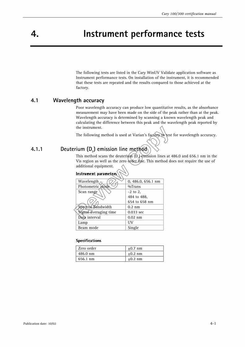
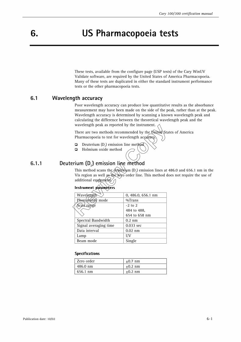
4.1.1 Deuterium (D2) emission line method This method scans the deuterium (D2) emission lines at 486.0 and 656.1 nm in the Vis region as well as the zero order line. This method does not require the use of additional equipment.
*OTUSVNFOU�QBSBNFUFST�
Wavelength 0, 486.0, 656.1 nm Photometric mode %Trans Scan range -2 to 2,
484 to 488, 654 to 658 nm
Spectral Bandwidth 0.2 nm Signal averaging time 0.033 sec Data interval 0.02 nm Lamp UV Beam mode Single
4QFDJGJDBUJPOT�
Zero order ±0.7 nm 486.0 nm ±0.2 nm 656.1 nm ±0.2 nm
Review
Copy
Cary 100/300 certification manual
4-2 Publication date: 10/02
8IBU�JG�NZ�JOTUSVNFOU�GBJMT�UP�NFFU�UIF�TQFDJGJDBUJPO �
�� Check that you have set the tolerances to values that are within the specifications of the instrument.
�� Recalibrate the wavelength drive mechanism by turning the instrument off and on again.
�� Check the deuterium (D2) lamp alignment and perform the wavelength accuracy test again.
�� If correct results still cannot be obtained, contact your local Varian Service office, as a service call may be required.
4.2 Wavelength reproducibility Poor wavelength reproducibility introduces errors in analytical results due to wavelength shifts. This test monitors the ability of the instrument to correctly return to the set wavelength repeatedly.
The following method is used at Varian’s factory to test for wavelength reproducibility.
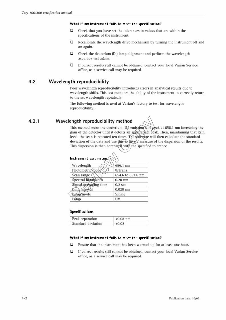
4.2.1 Wavelength reproducibility method This method scans the deuterium (D2) emission line peak at 656.1 nm increasing the gain of the detector until it detects an appropriate peak. Then, maintaining that gain level, the scan is repeated ten times. The software will then calculate the standard deviation of the data and use this to give a measure of the dispersion of the results. This dispersion is then compared with the specified tolerance.
*OTUSVNFOU�QBSBNFUFST�
Wavelength 656.1 nm Photometric mode %Trans Scan range 654.6 to 657.6 nm Spectral bandwidth 0.20 nm Signal averaging time 0.2 sec Data interval 0.020 nm Beam mode Single Lamp UV
4QFDJGJDBUJPOT�
Peak separation <0.08 nm Standard deviation <0.02
8IBU�JG�NZ�JOTUSVNFOU�GBJMT�UP�NFFU�UIF�TQFDJGJDBUJPO �
�� Ensure that the instrument has been warmed up for at least one hour.
�� If correct results still cannot be obtained, contact your local Varian Service office, as a service call may be required.
Review
Copy
Cary 100/300 certification manual
Publication date: 10/02 4-3
4.3 Baseline flatness All double or dual beam spectrophotometers function by comparing a sample in one light path to a reference in the other. If a wavelength scan is performed with the same material in both light paths, the response would be the natural baseline of the instrument. This baseline may not be a flat line. To compensate for this, all instruments have some form of baseline correction. Baseline Flatness is a measure of how well the instrument compensates for the natural baseline of the instrument and the reference material.
The following method is used at Varian’s factory to test for baseline flatness.
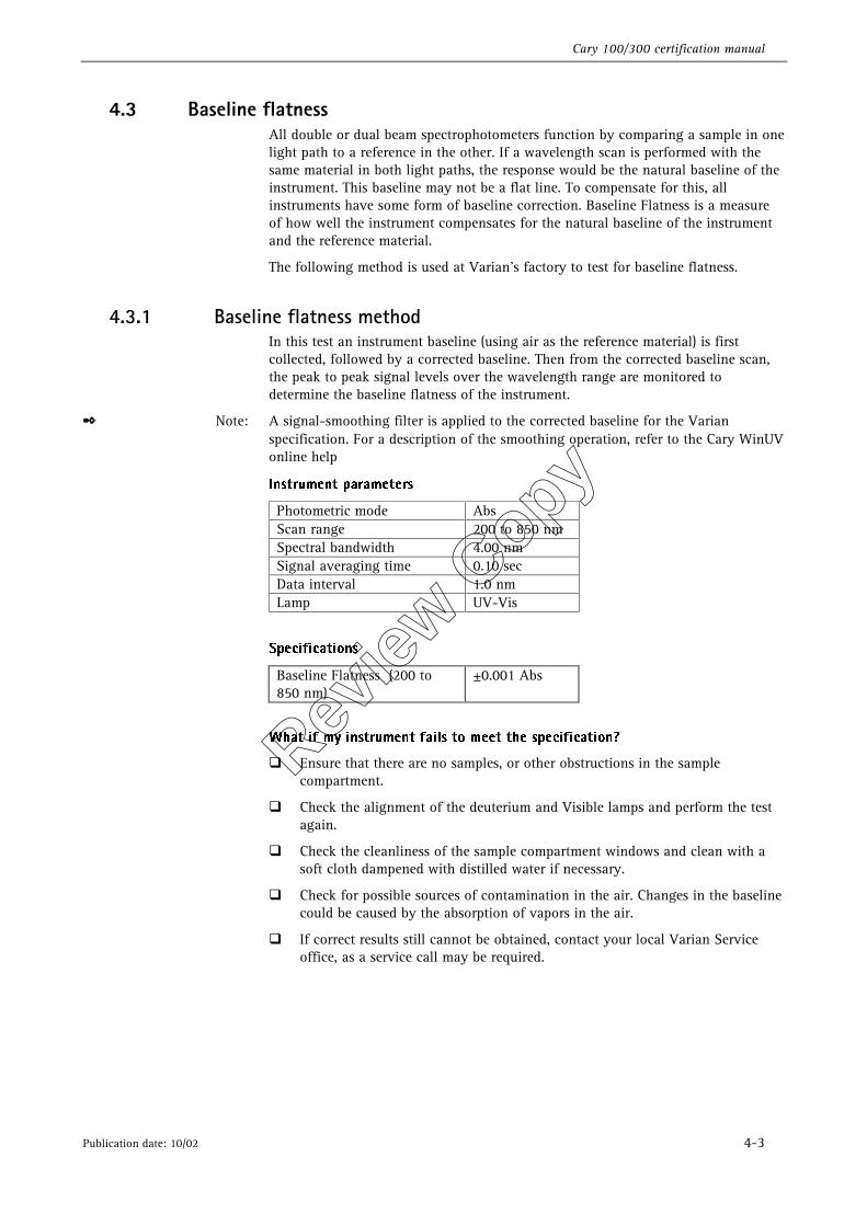
4.3.1 Baseline flatness method In this test an instrument baseline (using air as the reference material) is first collected, followed by a corrected baseline. Then from the corrected baseline scan, the peak to peak signal levels over the wavelength range are monitored to determine the baseline flatness of the instrument.
✒ Note: A signal-smoothing filter is applied to the corrected baseline for the Varian specification. For a description of the smoothing operation, refer to the Cary WinUV online help
*OTUSVNFOU�QBSBNFUFST�
Photometric mode Abs Scan range 200 to 850 nm Spectral bandwidth 4.00 nm Signal averaging time 0.10 sec Data interval 1.0 nm Lamp UV-Vis
4QFDJGJDBUJPOT�
Baseline Flatness (200 to 850 nm)
±0.001 Abs
8IBU�JG�NZ�JOTUSVNFOU�GBJMT�UP�NFFU�UIF�TQFDJGJDBUJPO �
�� Ensure that there are no samples, or other obstructions in the sample compartment.
�� Check the alignment of the deuterium and Visible lamps and perform the test again.
�� Check the cleanliness of the sample compartment windows and clean with a soft cloth dampened with distilled water if necessary.
�� Check for possible sources of contamination in the air. Changes in the baseline could be caused by the absorption of vapors in the air.
�� If correct results still cannot be obtained, contact your local Varian Service office, as a service call may be required.
Review
Copy
Cary 100/300 certification manual
4-4 Publication date: 10/02
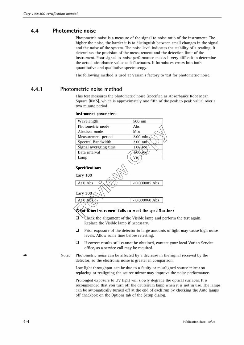
4.4 Photometric noise Photometric noise is a measure of the signal to noise ratio of the instrument. The higher the noise, the harder it is to distinguish between small changes in the signal and the noise of the system. The noise level indicates the stability of a reading. It determines the precision of the measurement and the detection limit of the instrument. Poor signal-to-noise performance makes it very difficult to determine the actual absorbance value as it fluctuates. It introduces errors into both quantitative and qualitative spectroscopy.
The following method is used at Varian’s factory to test for photometric noise.
4.4.1 Photometric noise method This test measures the photometric noise (specified as Absorbance Root Mean Square [RMS], which is approximately one fifth of the peak to peak value) over a two minute period
*OTUSVNFOU�QBSBNFUFST�
Wavelength 500 nm Photometric mode Abs Abscissa mode Min Measurement period 2.00 min Spectral Bandwidth 2.00 nm Signal averaging time 1.00 sec Data interval 1.00 sec Lamp Vis
�
4QFDJGJDBUJPOT�
Cary 100
At 0 Abs <0.000085 Abs Cary 300
At 0 Abs <0.000060 Abs �
8IBU�JG�NZ�JOTUSVNFOU�GBJMT�UP�NFFU�UIF�TQFDJGJDBUJPO �
�� Check the alignment of the Visible lamp and perform the test again. Replace the Visible lamp if necessary.
�� Prior exposure of the detector to large amounts of light may cause high noise levels. Allow some time before retesting.
�� If correct results still cannot be obtained, contact your local Varian Service office, as a service call may be required.
✒ Note: Photometric noise can be affected by a decrease in the signal received by the detector, so the electronic noise is greater in comparison.
Low light throughput can be due to a faulty or misaligned source mirror so replacing or realigning the source mirror may improve the noise performance.
Prolonged exposure to UV light will slowly degrade the optical surfaces. It is recommended that you turn off the deuterium lamp when it is not in use. The lamps can be automatically turned off at the end of each run by checking the Auto lamps off checkbox on the Options tab of the Setup dialog.
Review
Copy
Cary 100/300 certification manual
Publication date: 10/02 5-1
5. European Pharmacopoeia tests
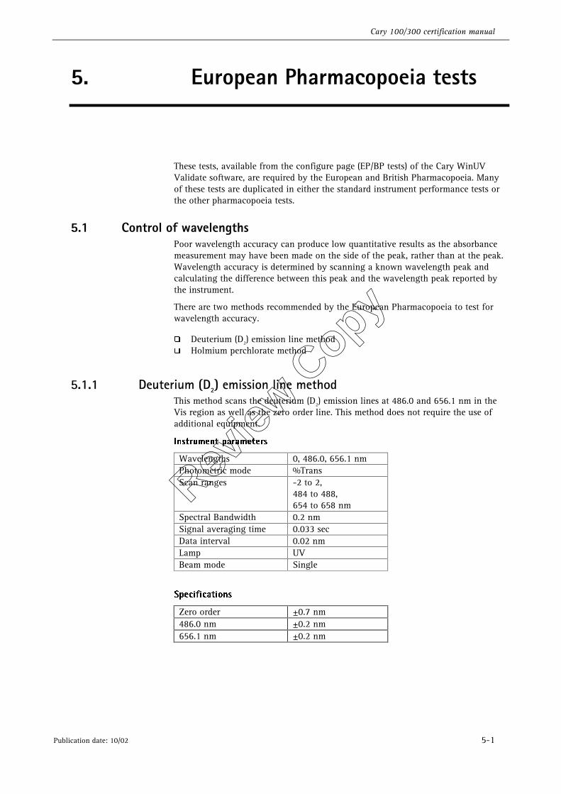
These tests, available from the configure page (EP/BP tests) of the Cary WinUV Validate software, are required by the European and British Pharmacopoeia. Many of these tests are duplicated in either the standard instrument performance tests or the other pharmacopoeia tests.
5.1 Control of wavelengths Poor wavelength accuracy can produce low quantitative results as the absorbance measurement may have been made on the side of the peak, rather than at the peak. Wavelength accuracy is determined by scanning a known wavelength peak and calculating the difference between this peak and the wavelength peak reported by the instrument.
There are two methods recommended by the European Pharmacopoeia to test for wavelength accuracy.
�� Deuterium (D2) emission line method �� Holmium perchlorate method
5.1.1 Deuterium (D2) emission line method This method scans the deuterium (D2) emission lines at 486.0 and 656.1 nm in the Vis region as well as the zero order line. This method does not require the use of additional equipment.
*OTUSVNFOU�QBSBNFUFST�
Wavelengths 0, 486.0, 656.1 nm Photometric mode %Trans Scan ranges -2 to 2,
484 to 488, 654 to 658 nm
Spectral Bandwidth 0.2 nm Signal averaging time 0.033 sec Data interval 0.02 nm Lamp UV Beam mode Single
4QFDJGJDBUJPOT�
Zero order ±0.7 nm 486.0 nm ±0.2 nm 656.1 nm ±0.2 nm
Review
Copy
Cary 100/300 certification manual
5-2 Publication date: 10/02
8IBU�JG�NZ�JOTUSVNFOU�GBJMT�UP�NFFU�UIF�TQFDJGJDBUJPO �
�� Check that you have set the tolerances to values that are within the specifications of the Cary instrument.
�� Recalibrate the wavelength drive mechanism by turning the instrument off and on again.
�� Check the deuterium (D2) lamp alignment and perform the wavelength accuracy test again.
�� If correct results still cannot be obtained, contact your local Varian Service office, as a service call may be required.
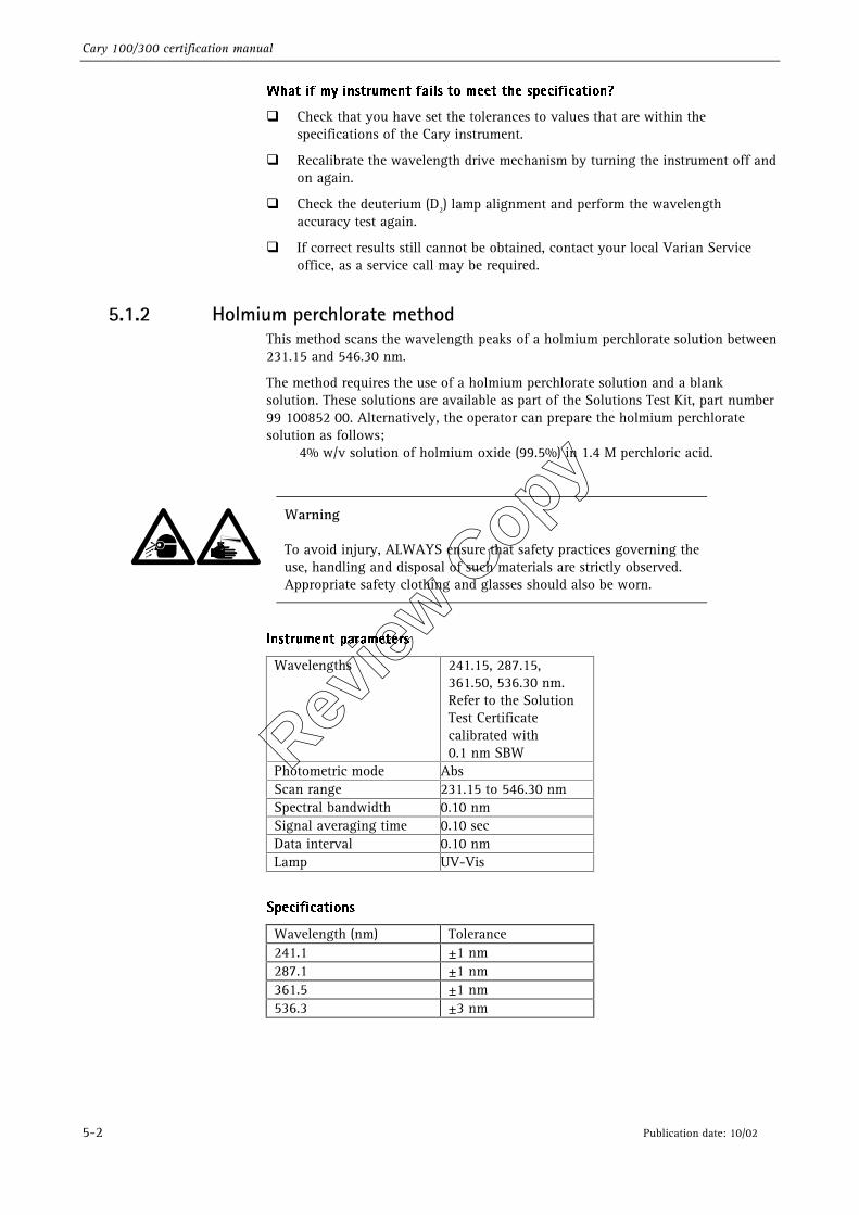
5.1.2 Holmium perchlorate method This method scans the wavelength peaks of a holmium perchlorate solution between 231.15 and 546.30 nm.
The method requires the use of a holmium perchlorate solution and a blank solution. These solutions are available as part of the Solutions Test Kit, part number 99 100852 00. Alternatively, the operator can prepare the holmium perchlorate solution as follows; 4% w/v solution of holmium oxide (99.5%) in 1.4 M perchloric acid.
Warning
To avoid injury, ALWAYS ensure that safety practices governing the use, handling and disposal of such materials are strictly observed. Appropriate safety clothing and glasses should also be worn.
*OTUSVNFOU�QBSBNFUFST�
Wavelengths 241.15, 287.15, 361.50, 536.30 nm. Refer to the Solution Test Certificate calibrated with 0.1 nm SBW
Photometric mode Abs Scan range 231.15 to 546.30 nm Spectral bandwidth 0.10 nm Signal averaging time 0.10 sec Data interval 0.10 nm Lamp UV-Vis
4QFDJGJDBUJPOT�
Wavelength (nm) Tolerance 241.1 ±1 nm 287.1 ±1 nm 361.5 ±1 nm 536.3 ±3 nm
Review
Copy
Cary 100/300 certification manual
Publication date: 10/02 5-3
8IBU�JG�NZ�JOTUSVNFOU�GBJMT�UP�NFFU�UIF�TQFDJGJDBUJPO �
Check that you have set the tolerances to values that are within the specifications of the instrument.
�� Recalibrate the wavelength drive mechanism by turning the instrument off and on again.
�� Check the deuterium (D2) and visible lamp alignments and perform the wavelength accuracy test again.
�� If correct results still cannot be obtained, contact your local Varian Service office, as a service call may be required.
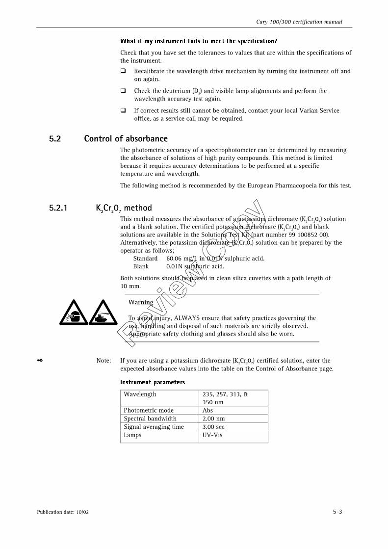
5.2 Control of absorbance The photometric accuracy of a spectrophotometer can be determined by measuring the absorbance of solutions of high purity compounds. This method is limited because it requires accuracy determinations to be performed at a specific temperature and wavelength.
The following method is recommended by the European Pharmacopoeia for this test.
5.2.1 K2Cr207 method This method measures the absorbance of a potassium dichromate (K2Cr207) solution and a blank solution. The certified potassium dichromate (K2Cr207) and blank solutions are available in the Solutions Test Kit (part number 99 100852 00). Alternatively, the potassium dichromate (K2Cr207) solution can be prepared by the operator as follows; Standard 60.06 mg/L in 0.01N sulphuric acid. Blank 0.01N sulphuric acid.
Both solutions should be placed in clean silica cuvettes with a path length of 10 mm.
Warning
To avoid injury, ALWAYS ensure that safety practices governing the use, handling and disposal of such materials are strictly observed. Appropriate safety clothing and glasses should also be worn.
✒ Note: If you are using a potassium dichromate (K2Cr207) certified solution, enter the expected absorbance values into the table on the Control of Absorbance page.
*OTUSVNFOU�QBSBNFUFST�
Wavelength 235, 257, 313, & 350 nm
Photometric mode Abs Spectral bandwidth 2.00 nm Signal averaging time 3.00 sec Lamps UV-Vis
Review
Copy
Cary 100/300 certification manual
5-4 Publication date: 10/02
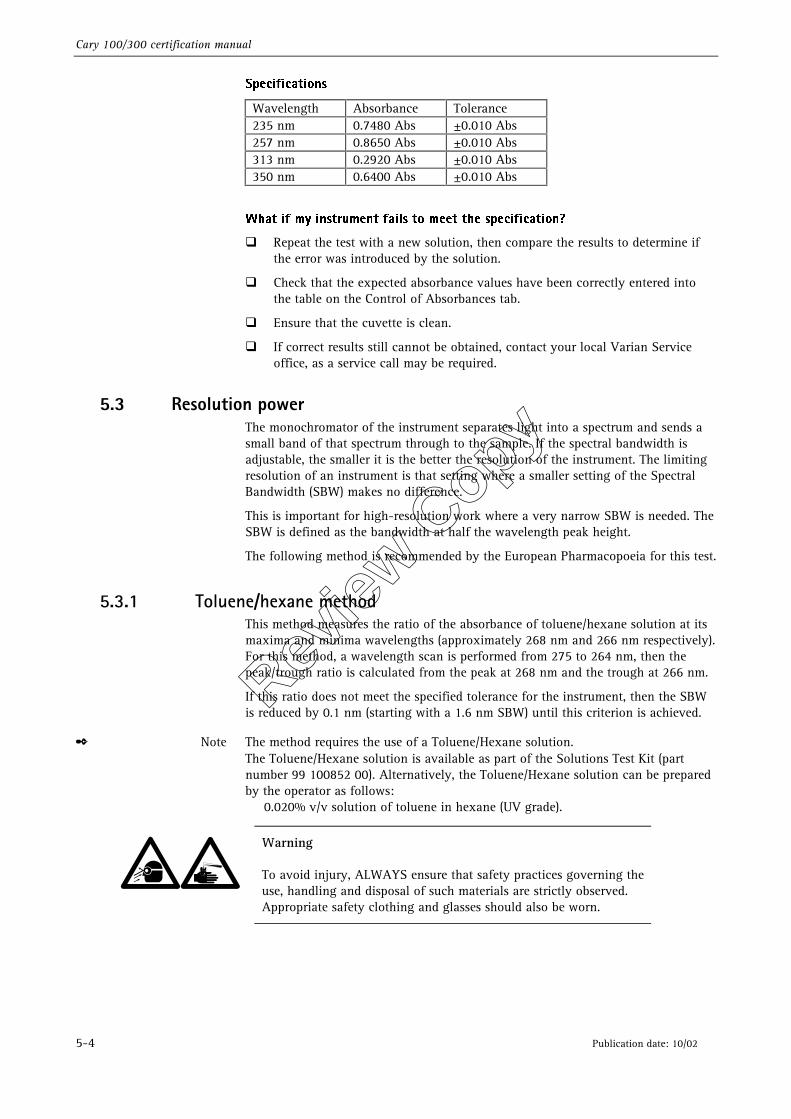
4QFDJGJDBUJPOT�
Wavelength Absorbance Tolerance 235 nm 0.7480 Abs ±0.010 Abs 257 nm 0.8650 Abs ±0.010 Abs 313 nm 0.2920 Abs ±0.010 Abs 350 nm 0.6400 Abs ±0.010 Abs
8IBU�JG�NZ�JOTUSVNFOU�GBJMT�UP�NFFU�UIF�TQFDJGJDBUJPO �
�� Repeat the test with a new solution, then compare the results to determine if the error was introduced by the solution.
�� Check that the expected absorbance values have been correctly entered into the table on the Control of Absorbances tab.
�� Ensure that the cuvette is clean.
�� If correct results still cannot be obtained, contact your local Varian Service office, as a service call may be required.
5.3 Resolution power The monochromator of the instrument separates light into a spectrum and sends a small band of that spectrum through to the sample. If the spectral bandwidth is adjustable, the smaller it is the better the resolution of the instrument. The limiting resolution of an instrument is that setting where a smaller setting of the Spectral Bandwidth (SBW) makes no difference.
This is important for high-resolution work where a very narrow SBW is needed. The SBW is defined as the bandwidth at half the wavelength peak height.
The following method is recommended by the European Pharmacopoeia for this test.
5.3.1 Toluene/hexane method This method measures the ratio of the absorbance of toluene/hexane solution at its maxima and minima wavelengths (approximately 268 nm and 266 nm respectively). For this method, a wavelength scan is performed from 275 to 264 nm, then the peak/trough ratio is calculated from the peak at 268 nm and the trough at 266 nm.
If this ratio does not meet the specified tolerance for the instrument, then the SBW is reduced by 0.1 nm (starting with a 1.6 nm SBW) until this criterion is achieved.
✒ Note The method requires the use of a Toluene/Hexane solution. The Toluene/Hexane solution is available as part of the Solutions Test Kit (part number 99 100852 00). Alternatively, the Toluene/Hexane solution can be prepared by the operator as follows: 0.020% v/v solution of toluene in hexane (UV grade).
Warning
To avoid injury, ALWAYS ensure that safety practices governing the use, handling and disposal of such materials are strictly observed. Appropriate safety clothing and glasses should also be worn.
Review
Copy
Cary 100/300 certification manual
Publication date: 10/02 5-5
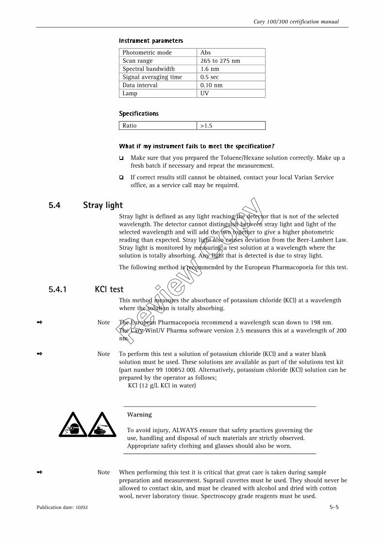
*OTUSVNFOU�QBSBNFUFST�
Photometric mode Abs Scan range 265 to 275 nm Spectral bandwidth 1.6 nm Signal averaging time 0.5 sec Data interval 0.10 nm Lamp UV
4QFDJGJDBUJPOT�
Ratio >1.5 �
8IBU�JG�NZ�JOTUSVNFOU�GBJMT�UP�NFFU�UIF�TQFDJGJDBUJPO �
�� Make sure that you prepared the Toluene/Hexane solution correctly. Make up a fresh batch if necessary and repeat the measurement.
�� If correct results still cannot be obtained, contact your local Varian Service office, as a service call may be required.
5.4 Stray light Stray light is defined as any light reaching the detector that is not of the selected wavelength. The detector cannot distinguish between stray light and light of the selected wavelength and will add the two together to give a higher photometric reading than expected. Stray light also causes deviation from the Beer-Lambert Law. Stray light is monitored by measuring a test solution at a wavelength where the solution is totally absorbing. Any light that is detected is due to stray light.
The following method is recommended by the European Pharmacopoeia for this test.
5.4.1 KCl test This method measures the absorbance of potassium chloride (KCl) at a wavelength where the solution is totally absorbing.
✒ Note The European Pharmacopoeia recommend a wavelength scan down to 198 nm. The Cary WinUV Pharma software version 2.5 measures this at a wavelength of 200 nm.
✒ Note To perform this test a solution of potassium chloride (KCl) and a water blank solution must be used. These solutions are available as part of the solutions test kit (part number 99 100852 00). Alternatively, potassium chloride (KCl) solution can be prepared by the operator as follows; KCl (12 g/L KCl in water)
Warning
To avoid injury, ALWAYS ensure that safety practices governing the use, handling and disposal of such materials are strictly observed. Appropriate safety clothing and glasses should also be worn.
✒ Note When performing this test it is critical that great care is taken during sample preparation and measurement. Suprasil cuvettes must be used. They should never be allowed to contact skin, and must be cleaned with alcohol and dried with cotton wool, never laboratory tissue. Spectroscopy grade reagents must be used.
Review
Copy
Cary 100/300 certification manual
5-6 Publication date: 10/02
✒ Note The major source of error in this measurement is fluorescence of the sample. It is also important that the light beam is kept away from the edges of the cuvette that can act as a non-attenuating light guide. For this reason, do not use unmasked microcells for this test. With the cuvette in the cell holder, hold the cell up to the light and look through the aperture. You should not be able to see the cuvette walls. Mask the cell holder if necessary to reduce the aperture width to 8 mm.
�
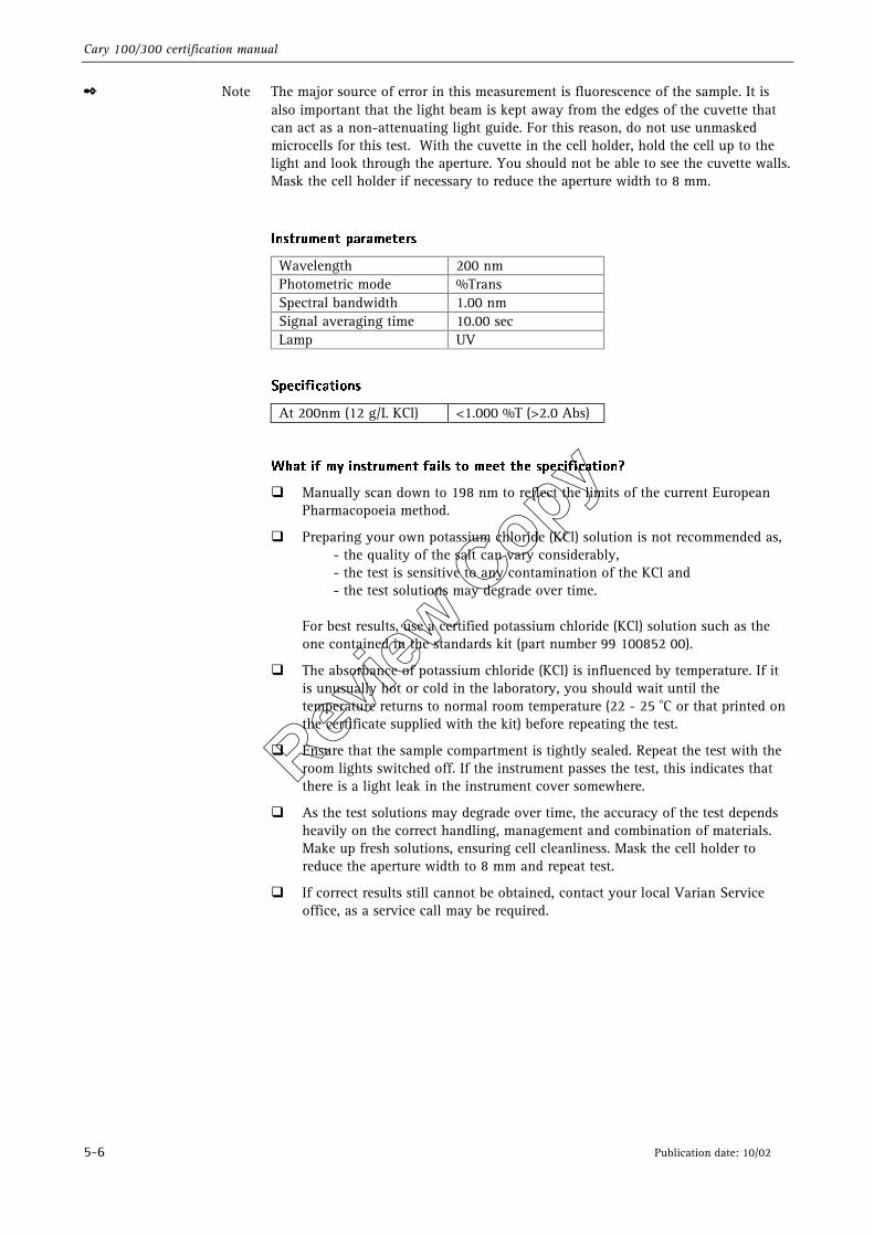
*OTUSVNFOU�QBSBNFUFST�
Wavelength 200 nm Photometric mode %Trans Spectral bandwidth 1.00 nm Signal averaging time 10.00 sec Lamp UV
4QFDJGJDBUJPOT�
At 200nm (12 g/L KCl) <1.000 %T (>2.0 Abs)
8IBU�JG�NZ�JOTUSVNFOU�GBJMT�UP�NFFU�UIF�TQFDJGJDBUJPO �
�� Manually scan down to 198 nm to reflect the limits of the current European Pharmacopoeia method.
�� Preparing your own potassium chloride (KCl) solution is not recommended as, - the quality of the salt can vary considerably, - the test is sensitive to any contamination of the KCl and - the test solutions may degrade over time. For best results, use a certified potassium chloride (KCl) solution such as the one contained in the standards kit (part number 99 100852 00).
�� The absorbance of potassium chloride (KCl) is influenced by temperature. If it is unusually hot or cold in the laboratory, you should wait until the temperature returns to normal room temperature (22 - 25 oC or that printed on the certificate supplied with the kit) before repeating the test.
�� Ensure that the sample compartment is tightly sealed. Repeat the test with the room lights switched off. If the instrument passes the test, this indicates that there is a light leak in the instrument cover somewhere.
�� As the test solutions may degrade over time, the accuracy of the test depends heavily on the correct handling, management and combination of materials. Make up fresh solutions, ensuring cell cleanliness. Mask the cell holder to reduce the aperture width to 8 mm and repeat test.
�� If correct results still cannot be obtained, contact your local Varian Service office, as a service call may be required.
Review
Copy
Cary 100/300 certification manual
Publication date: 10/02 6-1
6. US Pharmacopoeia tests
These tests, available from the configure page (USP tests) of the Cary WinUV Validate software, are required by the United States of America Pharmacopoeia. Many of these tests are duplicated in either the standard instrument performance tests or the other pharmacopoeia tests.
6.1 Wavelength accuracy Poor wavelength accuracy can produce low quantitative results as the absorbance measurement may have been made on the side of the peak, rather than at the peak. Wavelength accuracy is determined by scanning a known wavelength peak and calculating the difference between the theoretical wavelength peak and the wavelength peak as reported by the instrument.
There are two methods recommended by the United States of America Pharmacopoeia to test for wavelength accuracy.
�� Deuterium (D2) emission line method �� Holmium oxide method
6.1.1 Deuterium (D2) emission line method This method scans the deuterium (D2) emission lines at 486.0 and 656.1 nm in the Vis region as well as the zero order line. This method does not require the use of additional equipment.
*OTUSVNFOU�QBSBNFUFST�
Wavelength 0, 486.0, 656.1 nm Photometric mode %Trans Scan range -2 to 2
484 to 488, 654 to 658 nm
Spectral Bandwidth 0.2 nm Signal averaging time 0.033 sec Data interval 0.02 nm Lamp UV Beam mode Single
4QFDJGJDBUJPOT�
Zero order ±0.7 nm 486.0 nm ±0.2 nm 656.1 nm ±0.2 nm
Review
Copy
Cary 100/300 certification manual
6-2 Publication date: 10/02
8IBU�JG�NZ�JOTUSVNFOU�GBJMT�UP�NFFU�UIF�TQFDJGJDBUJPO �
�� Check that you have set the tolerances to values, which are within the specifications of the Cary instrument.
�� Recalibrate the wavelength drive mechanism by turning the instrument off and on again.
�� Check the deuterium (D2) lamp alignment and perform the wavelength accuracy test again.
�� If correct results still cannot be obtained, contact your local Varian Service office, as a service call may be required.
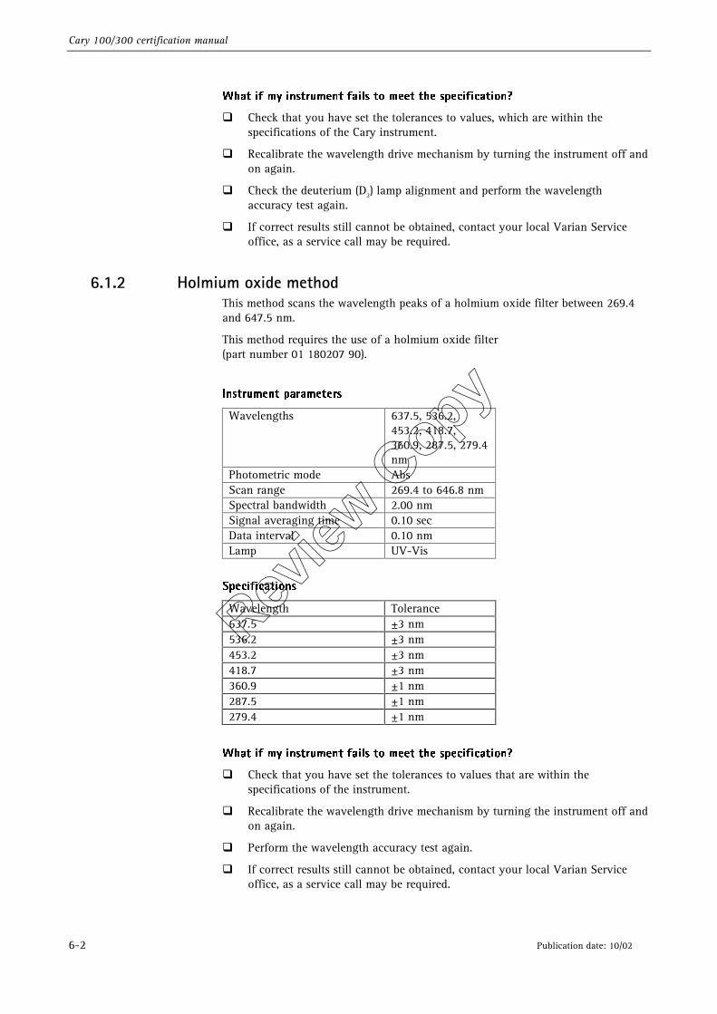
6.1.2 Holmium oxide method This method scans the wavelength peaks of a holmium oxide filter between 269.4 and 647.5 nm.
This method requires the use of a holmium oxide filter (part number 01 180207 90).
*OTUSVNFOU�QBSBNFUFST�
Wavelengths 637.5, 536.2, 453.2, 418.7, 360.9, 287.5, 279.4 nm
Photometric mode Abs Scan range 269.4 to 646.8 nm Spectral bandwidth 2.00 nm Signal averaging time 0.10 sec Data interval 0.10 nm Lamp UV-Vis
4QFDJGJDBUJPOT�
Wavelength Tolerance 637.5 ±3 nm 536.2 ±3 nm 453.2 ±3 nm 418.7 ±3 nm 360.9 ±1 nm 287.5 ±1 nm 279.4 ±1 nm
8IBU�JG�NZ�JOTUSVNFOU�GBJMT�UP�NFFU�UIF�TQFDJGJDBUJPO �
�� Check that you have set the tolerances to values that are within the specifications of the instrument.
�� Recalibrate the wavelength drive mechanism by turning the instrument off and on again.
�� Perform the wavelength accuracy test again.
�� If correct results still cannot be obtained, contact your local Varian Service office, as a service call may be required.
Review
Copy
Cary 100/300 certification manual
Publication date: 10/02 6-3
6.2 Photometric accuracy Photometric accuracy is determined by measuring a known absorbance value and calculating the difference between the expected absorbance value and the absorbance value as reported by the instrument.
✒ Note: Varian provides a kit of solutions (99 100852 00) containing certified standard solutions suitable for performing the photometric accuracy tests. If you are preparing your own solutions the expected absorbance and wavelength values will be advised in the relevant pharmacopoeia documentation. When using the Cary WinUV Validate software application ensure the correct wavelength and absorbance values are entered by selecting Tests, then the Photometric accuracy or Control of absorbances page. DO NOT use the default values.
There are two methods recommended by the United States of America Pharmacopoeia to test for photometric accuracy.
�� NIST filters method �� K2Cr207 method
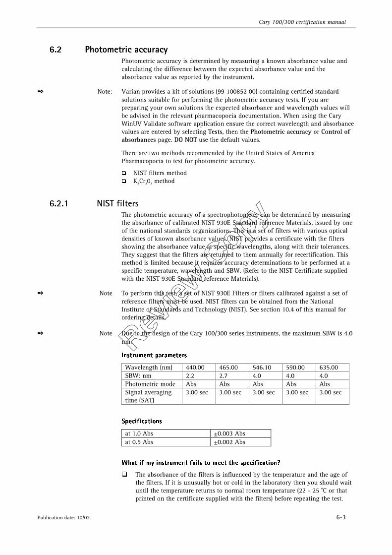
6.2.1 NIST filters The photometric accuracy of a spectrophotometer can be determined by measuring the absorbance of calibrated NIST 930E Standard reference Materials, issued by one of the national standards organizations. This is a set of filters with various optical densities of known absorbance values. NIST provides a certificate with the filters showing the absorbance value at specific wavelengths, along with their tolerances. They suggest that the filters are returned to them annually for recertification. This method is limited because it requires accuracy determinations to be performed at a specific temperature, wavelength and SBW. (Refer to the NIST Certificate supplied with the NIST 930E Standard reference Materials).
✒ Note To perform this test, a set of NIST 930E Filters or filters calibrated against a set of reference filters must be used. NIST filters can be obtained from the National Institute of Standards and Technology (NIST). See section 10.4 of this manual for ordering details.
✒ Note Due to the design of the Cary 100/300 series instruments, the maximum SBW is 4.0 nm.
*OTUSVNFOU�QBSBNFUFST�
Wavelength (nm) 440.00 465.00 546.10 590.00 635.00 SBW: nm 2.2 2.7 4.0 4.0 4.0 Photometric mode Abs Abs Abs Abs Abs Signal averaging time (SAT)
3.00 sec 3.00 sec 3.00 sec 3.00 sec 3.00 sec
�
4QFDJGJDBUJPOT�
at 1.0 Abs ±0.003 Abs at 0.5 Abs ±0.002 Abs
8IBU�JG�NZ�JOTUSVNFOU�GBJMT�UP�NFFU�UIF�TQFDJGJDBUJPO �
�� The absorbance of the filters is influenced by the temperature and the age of the filters. If it is unusually hot or cold in the laboratory then you should wait until the temperature returns to normal room temperature (22 - 25 oC or that printed on the certificate supplied with the filters) before repeating the test.
Review
Copy
Cary 100/300 certification manual
6-4 Publication date: 10/02
�� If you have had the filter set for several years you may need to return it to the issuing body for recalibration.
�� Check the result a second time, paying special care with the positioning of the NIST filter.
�� If correct results still cannot be obtained, contact your local Varian Service office, as a service call may be required.
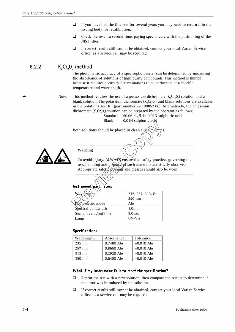
6.2.2 K2Cr207 method The photometric accuracy of a spectrophotometer can be determined by measuring the absorbance of solutions of high purity compounds. This method is limited because it requires accuracy determinations to be performed at a specific temperature and wavelength.
✒ Note: This method requires the use of a potassium dichromate (K2Cr207) solution and a blank solution. The potassium dichromate (K2Cr207) and blank solutions are available in the Solutions Test Kit (part number 99 100852 00). Alternatively, the potassium dichromate (K2Cr207) solution can be prepared by the operator as follows; Standard 60.06 mg/L in 0.01N sulphuric acid Blank 0.01N sulphuric acid
Both solutions should be placed in clean silica cuvettes.
Warning
To avoid injury, ALWAYS ensure that safety practices governing the use, handling and disposal of such materials are strictly observed. Appropriate safety clothing and glasses should also be worn.
*OTUSVNFOU�QBSBNFUFST�
Wavelengths 235, 257, 313, & 350 nm
Photometric mode Abs Spectral bandwidth 1.0nm Signal averaging time 3.0 sec Lamp UV-Vis
�
4QFDJGJDBUJPOT�
Wavelength Absorbance Tolerance 235 nm 0.7480 Abs ±0.010 Abs 257 nm 0.8650 Abs ±0.010 Abs 313 nm 0.2920 Abs ±0.010 Abs 350 nm 0.6400 Abs ±0.010 Abs
8IBU�JG�NZ�JOTUSVNFOU�GBJMT�UP�NFFU�UIF�TQFDJGJDBUJPO �
�� Repeat the test with a new solution, then compare the results to determine if the error was introduced by the solution.
�� If correct results still cannot be obtained, contact your local Varian Service office, as a service call may be required.
Review
Copy
Cary 100/300 certification manual
Publication date: 10/02 7-1
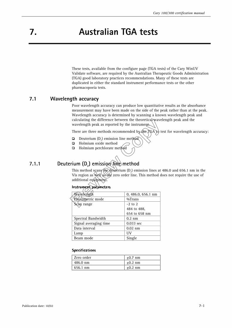
7. Australian TGA tests
These tests, available from the configure page (TGA tests) of the Cary WinUV Validate software, are required by the Australian Therapeutic Goods Administration (TGA) good laboratory practices recommendations. Many of these tests are duplicated in either the standard instrument performance tests or the other pharmacopoeia tests.
7.1 Wavelength accuracy Poor wavelength accuracy can produce low quantitative results as the absorbance measurement may have been made on the side of the peak rather than at the peak. Wavelength accuracy is determined by scanning a known wavelength peak and calculating the difference between the theoretical wavelength peak and the wavelength peak as reported by the instrument.
There are three methods recommended by the TGA to test for wavelength accuracy:
�� Deuterium (D2) emission line method �� Holmium oxide method �� Holmium perchlorate method
7.1.1 Deuterium (D2) emission line method This method scans the deuterium (D2) emission lines at 486.0 and 656.1 nm in the Vis region as well as the zero order line. This method does not require the use of additional equipment.
*OTUSVNFOU�QBSBNFUFST�
Wavelength 0, 486.0, 656.1 nm Photometric mode %Trans Scan range -2 to 2
484 to 488, 654 to 658 nm
Spectral Bandwidth 0.2 nm Signal averaging time 0.033 sec Data interval 0.02 nm Lamp UV Beam mode Single
4QFDJGJDBUJPOT�
Zero order ±0.7 nm 486.0 nm ±0.2 nm 656.1 nm ±0.2 nm
Review
Copy
Cary 100/300 certification manual
7-2 Publication date: 10/02
8IBU�JG�NZ�JOTUSVNFOU�GBJMT�UP�NFFU�UIF�TQFDJGJDBUJPO �
�� Check that you have set the tolerances to values that are within the specifications of the Cary instrument.
�� Recalibrate the wavelength drive mechanism by turning the instrument off and on again.
�� Check the deuterium (D2) lamp alignment and perform the wavelength accuracy test again.
�� If correct results still cannot be obtained, contact your local Varian Service office, as a service call may be required.
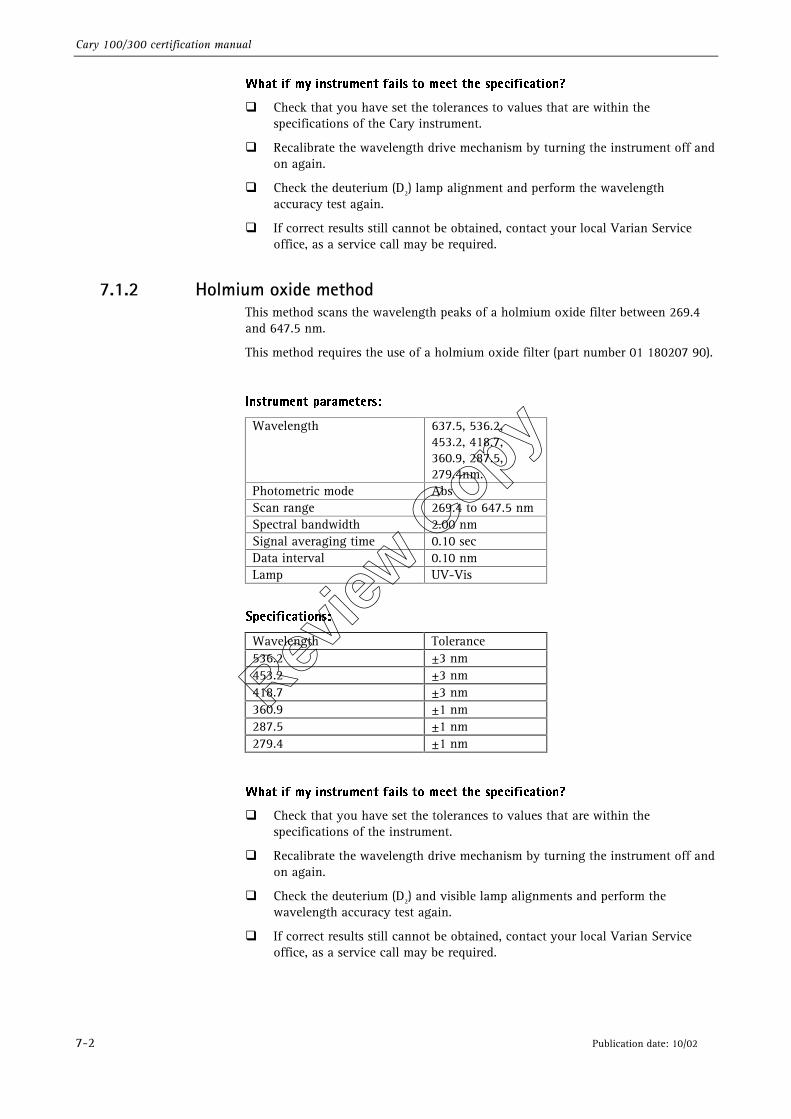
7.1.2 Holmium oxide method This method scans the wavelength peaks of a holmium oxide filter between 269.4 and 647.5 nm.
This method requires the use of a holmium oxide filter (part number 01 180207 90).
*OTUSVNFOU�QBSBNFUFST��
Wavelength 637.5, 536.2, 453.2, 418.7, 360.9, 287.5, 279.4nm.
Photometric mode Abs Scan range 269.4 to 647.5 nm Spectral bandwidth 2.00 nm Signal averaging time 0.10 sec Data interval 0.10 nm Lamp UV-Vis
4QFDJGJDBUJPOT��
Wavelength Tolerance 536.2 ±3 nm 453.2 ±3 nm 418.7 ±3 nm 360.9 ±1 nm 287.5 ±1 nm 279.4 ±1 nm
8IBU�JG�NZ�JOTUSVNFOU�GBJMT�UP�NFFU�UIF�TQFDJGJDBUJPO �
�� Check that you have set the tolerances to values that are within the specifications of the instrument.
�� Recalibrate the wavelength drive mechanism by turning the instrument off and on again.
�� Check the deuterium (D2) and visible lamp alignments and perform the wavelength accuracy test again.
�� If correct results still cannot be obtained, contact your local Varian Service office, as a service call may be required.
Review
Copy
Cary 100/300 certification manual
Publication date: 10/02 7-3
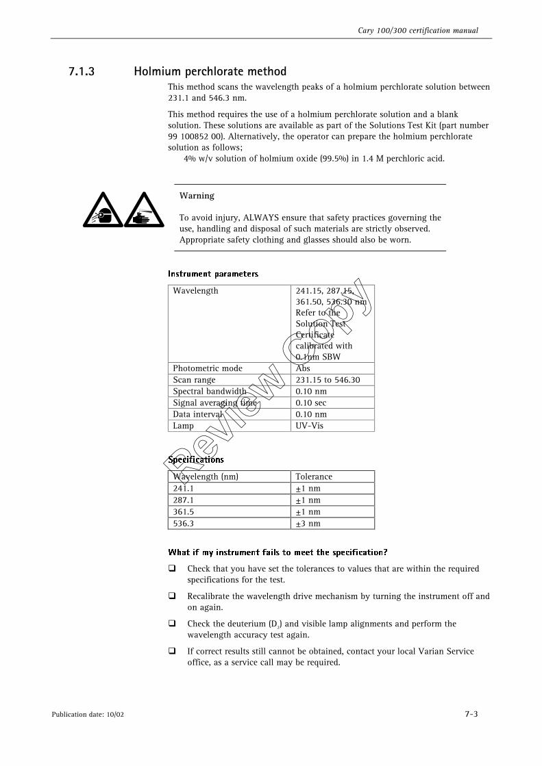
7.1.3 Holmium perchlorate method This method scans the wavelength peaks of a holmium perchlorate solution between 231.1 and 546.3 nm.
This method requires the use of a holmium perchlorate solution and a blank solution. These solutions are available as part of the Solutions Test Kit (part number 99 100852 00). Alternatively, the operator can prepare the holmium perchlorate solution as follows; 4% w/v solution of holmium oxide (99.5%) in 1.4 M perchloric acid.
Warning
To avoid injury, ALWAYS ensure that safety practices governing the use, handling and disposal of such materials are strictly observed. Appropriate safety clothing and glasses should also be worn.
*OTUSVNFOU�QBSBNFUFST�
Wavelength 241.15, 287.15, 361.50, 536.30 nm Refer to the Solution Test Certificate calibrated with 0.1nm SBW
Photometric mode Abs Scan range 231.15 to 546.30 Spectral bandwidth 0.10 nm Signal averaging time 0.10 sec Data interval 0.10 nm Lamp UV-Vis
4QFDJGJDBUJPOT�
Wavelength (nm) Tolerance 241.1 ±1 nm 287.1 ±1 nm 361.5 ±1 nm 536.3 ±3 nm
�
8IBU�JG�NZ�JOTUSVNFOU�GBJMT�UP�NFFU�UIF�TQFDJGJDBUJPO �
�� Check that you have set the tolerances to values that are within the required specifications for the test.
�� Recalibrate the wavelength drive mechanism by turning the instrument off and on again.
�� Check the deuterium (D2) and visible lamp alignments and perform the wavelength accuracy test again.
�� If correct results still cannot be obtained, contact your local Varian Service office, as a service call may be required.
Review
Copy
Cary 100/300 certification manual
7-4 Publication date: 10/02
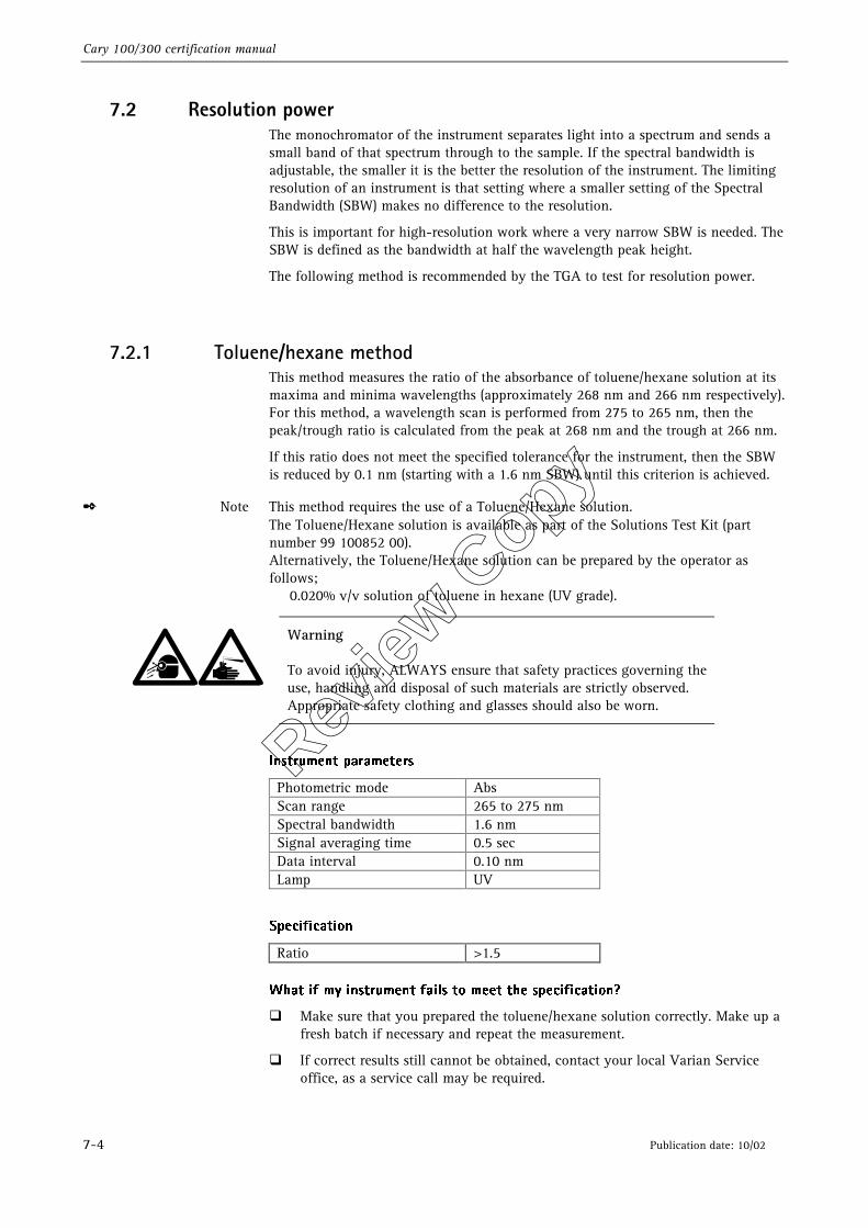
7.2 Resolution power The monochromator of the instrument separates light into a spectrum and sends a small band of that spectrum through to the sample. If the spectral bandwidth is adjustable, the smaller it is the better the resolution of the instrument. The limiting resolution of an instrument is that setting where a smaller setting of the Spectral Bandwidth (SBW) makes no difference to the resolution.
This is important for high-resolution work where a very narrow SBW is needed. The SBW is defined as the bandwidth at half the wavelength peak height.
The following method is recommended by the TGA to test for resolution power.
7.2.1 Toluene/hexane method This method measures the ratio of the absorbance of toluene/hexane solution at its maxima and minima wavelengths (approximately 268 nm and 266 nm respectively). For this method, a wavelength scan is performed from 275 to 265 nm, then the peak/trough ratio is calculated from the peak at 268 nm and the trough at 266 nm.
If this ratio does not meet the specified tolerance for the instrument, then the SBW is reduced by 0.1 nm (starting with a 1.6 nm SBW) until this criterion is achieved.
✒ Note This method requires the use of a Toluene/Hexane solution. The Toluene/Hexane solution is available as part of the Solutions Test Kit (part number 99 100852 00). Alternatively, the Toluene/Hexane solution can be prepared by the operator as follows; 0.020% v/v solution of toluene in hexane (UV grade).
Warning
To avoid injury, ALWAYS ensure that safety practices governing the use, handling and disposal of such materials are strictly observed. Appropriate safety clothing and glasses should also be worn.
�
*OTUSVNFOU�QBSBNFUFST�
Photometric mode Abs Scan range 265 to 275 nm Spectral bandwidth 1.6 nm Signal averaging time 0.5 sec Data interval 0.10 nm Lamp UV
�
4QFDJGJDBUJPO�
Ratio >1.5 8IBU�JG�NZ�JOTUSVNFOU�GBJMT�UP�NFFU�UIF�TQFDJGJDBUJPO �
�� Make sure that you prepared the toluene/hexane solution correctly. Make up a fresh batch if necessary and repeat the measurement.
�� If correct results still cannot be obtained, contact your local Varian Service office, as a service call may be required.
Review
Copy
Cary 100/300 certification manual
Publication date: 10/02 7-5
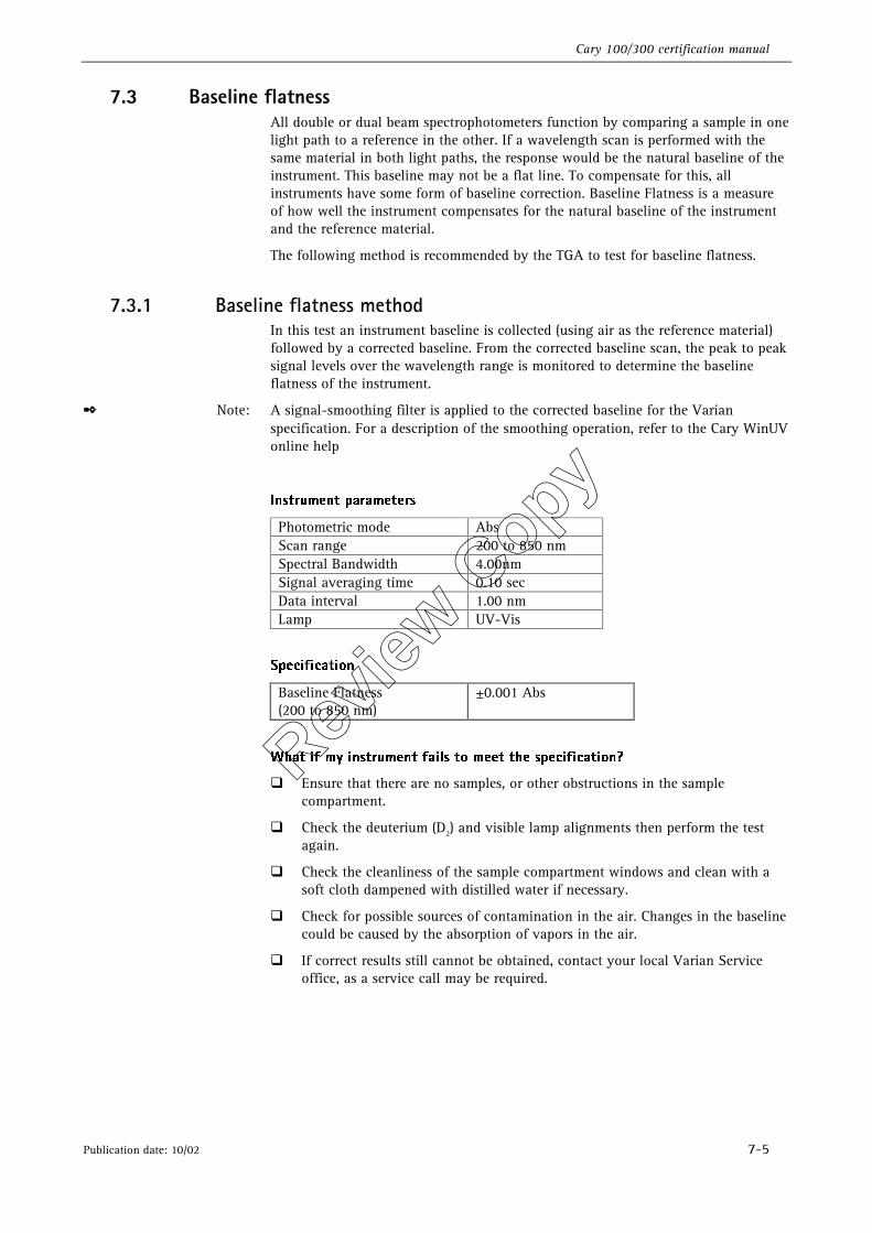
7.3 Baseline flatness All double or dual beam spectrophotometers function by comparing a sample in one light path to a reference in the other. If a wavelength scan is performed with the same material in both light paths, the response would be the natural baseline of the instrument. This baseline may not be a flat line. To compensate for this, all instruments have some form of baseline correction. Baseline Flatness is a measure of how well the instrument compensates for the natural baseline of the instrument and the reference material.
The following method is recommended by the TGA to test for baseline flatness.
7.3.1 Baseline flatness method In this test an instrument baseline is collected (using air as the reference material) followed by a corrected baseline. From the corrected baseline scan, the peak to peak signal levels over the wavelength range is monitored to determine the baseline flatness of the instrument.
✒ Note: A signal-smoothing filter is applied to the corrected baseline for the Varian specification. For a description of the smoothing operation, refer to the Cary WinUV online help
*OTUSVNFOU�QBSBNFUFST�
Photometric mode Abs Scan range 200 to 850 nm Spectral Bandwidth 4.00nm Signal averaging time 0.10 sec Data interval 1.00 nm Lamp UV-Vis
4QFDJGJDBUJPO�
Baseline Flatness (200 to 850 nm)
±0.001 Abs
�
8IBU�JG�NZ�JOTUSVNFOU�GBJMT�UP�NFFU�UIF�TQFDJGJDBUJPO �
�� Ensure that there are no samples, or other obstructions in the sample compartment.
�� Check the deuterium (D2) and visible lamp alignments then perform the test again.
�� Check the cleanliness of the sample compartment windows and clean with a soft cloth dampened with distilled water if necessary.
�� Check for possible sources of contamination in the air. Changes in the baseline could be caused by the absorption of vapors in the air.
�� If correct results still cannot be obtained, contact your local Varian Service office, as a service call may be required.
Review
Copy
Cary 100/300 certification manual
7-6 Publication date: 10/02
7.4 Stray light Stray light is defined as any light that gets to the detector that is not of the selected wavelength. The detector cannot distinguish between stray light and light of the selected wavelength and will add the two together to give a higher photometric reading than expected. Stray light also causes deviation from the Beer-Lambert Law. Stray light is monitored by measuring a test solution at a wavelength where the solution is totally absorbing. Any light that is detected is due to stray light.
There are two methods recommended by the TGA to test for stray light:
�� KCl (12 g/L KCl in water) test �� NaNO2/ K2Cr207 for 370 nm test
7.4.1 KCl test This method measures the absorbance of potassium chloride (KCl) at a wavelength where the solution is totally absorbing.
✒ Note The European Pharmacopoeia recommend a wavelength of 198 nm. The Cary WinUV software version 2.5 measures at a wavelength of 200 nm.
✒ Note To perform this test a solution of potassium chloride (KCl) and a water blank solution must be used. These solutions are available as part of the solutions test kit (part number 99 100852 00). Alternatively, potassium chloride (KCl) solution can be prepared by the operator as follows: KCl (12 g/L KCl in water)
Warning
To avoid injury, ALWAYS ensure that safety practices governing the use, handling and disposal of such materials are strictly observed. Appropriate safety clothing and glasses should also be worn.
✒ Note When performing this test it is critical that great care is taken during sample preparation and measurement. Suprasil cuvettes must be used. They should never be allowed to contact skin, and must be cleaned with alcohol and dried with cotton wool, never laboratory tissue. Spectroscopy grade reagents must be used.
✒ Note The chief source of error in this measurement is fluorescence of the sample. It is also important that the light beam is kept away from the edges of the cuvette that can act as a non-attenuating light guide. For this reason, you must use masked microcells for this test. With the cuvette in the cell holder, hold the cell up to the light and look through the aperture. You should not be able to see the cuvette walls. Mask the cell holder if necessary to reduce the aperture width to 8 mm.
*OTUSVNFOU�QBSBNFUFST�
Wavelength 200 nm Photometric mode %Trans Spectral bandwidth 1.00 nm Signal averaging time 10 sec Lamp UV
Review
Copy
Cary 100/300 certification manual
Publication date: 10/02 7-7
4QFDJGJDBUJPO�
At 200nm (12 g/L KCl) <1.000 %T ( >2.0 Abs )
8IBU�JG�NZ�JOTUSVNFOU�GBJMT�UP�NFFU�UIF�TQFDJGJDBUJPO �
�� Manually scan down to 198 nm to reflect the limits of the current European Pharmacopoeia method.
�� Preparing your own potassium chloride (KCl) solution is not recommended as, - the quality of the salt can vary considerably, - the test is sensitive to any contamination of the KCl and - the test solutions may degrade over time. For best results, use a certified potassium chloride (KCl) solution such as the one contained in the standards kit (part number 99 100852 00).
�� The absorbance of potassium chloride (KCl) is influenced by temperature. If it is unusually hot or cold in the laboratory, you should wait until the temperature returns to normal (or that printed on the certificate supplied with the kit) before repeating the test.
�� Ensure that the sample compartment is tightly sealed. Repeat the test with the room lights turned off. If the instrument passes the test, this indicates that there is a light leak in the instrument cover somewhere.
�� As the test solutions may degrade over time, the accuracy of the test depends heavily on the correct handling, management and combination of materials. Make up fresh solutions, ensuring cell cleanliness. Mask the cell holder to reduce the aperture width to 8 mm and repeat test.
�� If correct results still cannot be obtained, contact your local Varian Service office, as a service call may be required.
7.4.2 NaNO2/K2Cr207 at 370 nm This method measures the absorbance of either sodium nitrite (NaNO2) or potassium dichromate (K2Cr207) at a wavelength of 370nm.
✒ Note To perform this test, a solution of either sodium nitrite (NaNO2) or potassium dichromate (K2Cr207) must be prepared by the operator. The sodium nitrite (NaNO2) solution is prepared as follows; 50 g/L NaNO2 in water The potassium dichromate (K2Cr207) solution is prepared as follows; 0.25 g/L K2Cr207 in aqueous 0.05 M KOH.
Warning
To avoid injury, ALWAYS ensure that safety practices governing the use, handling and disposal of such materials are strictly observed. Appropriate safety clothing and glasses should also be worn.
✒ Note When performing this test it is critical that great care is taken during sample preparation and measurement. Suprasil cuvettes must be used. They should never be allowed to contact skin, and must be cleaned with alcohol and dried with cotton wool, never laboratory tissue. Spectroscopy grade reagents must also be used.
Review
Copy
Cary 100/300 certification manual
7-8 Publication date: 10/02
✒ Note The chief source of error in this measurement is fluorescence of the sample. It is also important that the light beam is kept away from the edges of the cuvette that can act as a non-attenuating light guide. For this reason, you must use masked microcells for this test. With the cuvette in the cell holder, hold the cell up to the light and look through the aperture. You should not be able to see the cuvette walls. Mask the cell holder if necessary to reduce the aperture width to 8 mm.
�
*OTUSVNFOU�QBSBNFUFST�
Wavelength 370 nm Photometric mode %Trans Spectral bandwidth 2.00 nm Signal averaging time 10 sec Lamp UV-Vis
�
4QFDJGJDBUJPOT�
At 370 nm (50mg/L NaNO2) <0.05 %T At 370 nm (0.25 g/L K2Cr207) <1.0 %T
�
8IBU�JG�NZ�JOTUSVNFOU�GBJMT�UP�NFFU�UIF�TQFDJGJDBUJPO �
�� Ensure that the sample compartment is tightly sealed. Repeat the test with the room lights turned off. If the instrument passes the test, this indicates that there is a light leak in the instrument cover somewhere.
�� As the test solutions may degrade over time, the accuracy of the test depends heavily on the correct handling, management and combination of materials. Make up fresh solutions, ensuring cell cleanliness. Mask the cell holder to reduce the aperture width to 8 mm and repeat test.
�� If correct results still cannot be obtained, contact your local Varian Service office, as a service call may be required.
7.5 Photometric accuracy Photometric accuracy is determined by measuring a known absorbance value and calculating the difference between the theoretical absorbance value and the absorbance value as reported by the instrument.
There are three methods recommended by the TGA to test for photometric accuracy:
�� NIST filters method �� K2Cr207 method �� KNO3 method
7.5.1 NIST filters The photometric accuracy of a spectrophotometer can be determined by measuring the absorbance of calibrated NIST 930E standard reference materials, issued by one of the national standards organizations. This is a set of filters with various optical densities of know absorbance values. NIST provides a certificate with the filters showing the absorbance value at specific wavelengths, along with their tolerances. They suggest the filters are returned to them annually for recertification. This method is limited because it requires accuracy determinations to be performed at a specific temperature, wavelength and SBW. (Refer to the NIST Certificate supplied with the NIST 930E standard reference materials.)
Review
Copy
Cary 100/300 certification manual
Publication date: 10/02 7-9
✒ Note To perform this test a set of NIST 930E Filters or filters calibrated against a reference set of filters must be used. This filter set can be obtained from the National Institute of Standards and Technology (NIST). See section 10.4 of this manual for ordering details.
✒ Note Due to the design of the Cary 100/300 series instruments, the maximum SBW is 4.0 nm.
*OTUSVNFOU�QBSBNFUFST�
Wavelength (nm) 440.00 465.00 546.10 590.00 635.00 Photometric mode Abs Abs Abs Abs Abs SBW nm 2.2 2.7 4.0 4.0 4.0 Signal averaging time (SAT)
3.00 sec 3.00 sec 3.00 sec 3.00 sec 3.00 sec
4QFDJGJDBUJPO�
at 1.0 Abs ±0.005 Abs 8IBU�JG�NZ�JOTUSVNFOU�GBJMT�UP�NFFU�UIF�TQFDJGJDBUJPO �
�� The absorbance of the filters is influenced by the temperature and the age of the filters. If it is unusually hot or cold in the laboratory then you should wait until the temperature returns to normal (or that printed on the certificate supplied with the filters) before repeating the test.
�� If you have had the filter set for several years you may need to return it to the issuing body for recalibration.
�� Check the result a second time, paying special care with the positioning of the NIST filter.
�� If correct results still cannot be obtained, contact your local Varian Service office, as a service call may be required.
7.5.2 K2Cr207 method The photometric accuracy of a spectrophotometer can be determined by measuring the absorbance of solutions of high purity compounds. A test solution can be prepared by the operator. This method is limited because it requires accuracy determinations to be performed at a specific temperature and wavelength.
✒ Note This method requires the use of a potassium dichromate (K2Cr207) solution and a blank solution. The potassium dichromate (K2Cr207) and blank solutions are available in the Solutions Test Kit (part number 99 100852 00).
Alternatively, the potassium dichromate (K2Cr207) solution can be prepared by the operator as follows; Standard 60.06 mg/L in 0.01N sulphuric acid. Blank 0.01N sulphuric acid
Both solutions should be placed in clean silica cuvettes.
Warning
To avoid injury, ALWAYS ensure that safety practices governing the use, handling and disposal of such materials are strictly observed. Appropriate safety clothing and glasses should also be worn.
�
�
Review
Copy
Cary 100/300 certification manual
7-10 Publication date: 10/02
*OTUSVNFOU�QBSBNFUFST�
Wavelength 235, 257, 313, & 350 nm
Photometric mode Abs Spectral bandwidth 2.00 nm Signal averaging time 3.00 sec Lamp UV-Vis
�
4QFDJGJDBUJPOT�
Wavelength Absorbance Tolerance 235 nm 0.7480 Abs ±0.010 Abs 257 nm 0.8650 Abs ±0.010 Abs 313 nm 0.2920 Abs ±0.010 Abs 350 nm 0.6400 Abs ±0.010 Abs
8IBU�JG�NZ�JOTUSVNFOU�GBJMT�UP�NFFU�UIF�TQFDJGJDBUJPO �
�� Repeat the test with a new solution, then compare the results to determine if the error was introduced by the solution.
�� If correct results still cannot be obtained, contact your local Varian Service office, as a service call may be required.
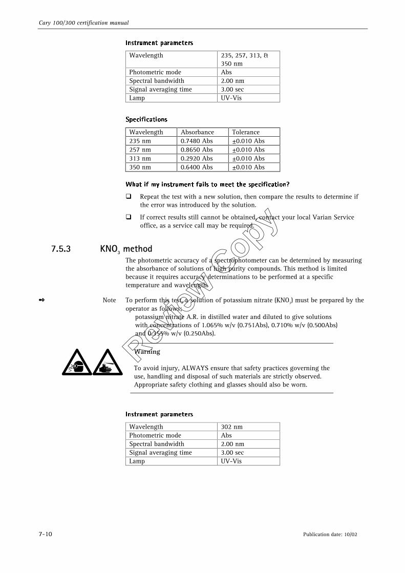
7.5.3 KNO3 method The photometric accuracy of a spectrophotometer can be determined by measuring the absorbance of solutions of high purity compounds. This method is limited because it requires accuracy determinations to be performed at a specific temperature and wavelength.
✒ Note To perform this test, a solution of potassium nitrate (KNO3) must be prepared by the operator as follows; potassium nitrate A.R. in distilled water and diluted to give solutions with concentrations of 1.065% w/v (0.751Abs), 0.710% w/v (0.500Abs) and 0.355% w/v (0.250Abs).
Warning
To avoid injury, ALWAYS ensure that safety practices governing the use, handling and disposal of such materials are strictly observed. Appropriate safety clothing and glasses should also be worn.
*OTUSVNFOU�QBSBNFUFST�
Wavelength 302 nm Photometric mode Abs Spectral bandwidth 2.00 nm Signal averaging time 3.00 sec Lamp UV-Vis
�
Review
Copy
Cary 100/300 certification manual
Publication date: 10/02 7-11
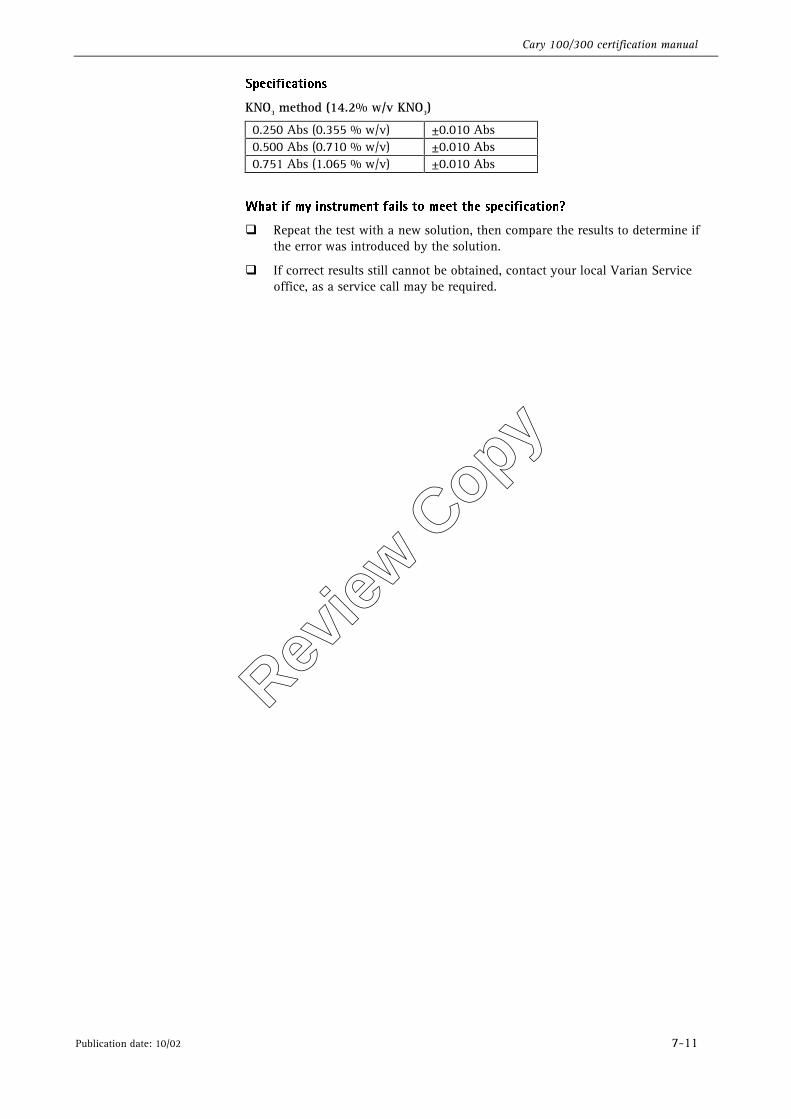
4QFDJGJDBUJPOT�
KNO3 method (14.2% w/v KNO3)
0.250 Abs (0.355 % w/v) ±0.010 Abs 0.500 Abs (0.710 % w/v) ±0.010 Abs 0.751 Abs (1.065 % w/v) ±0.010 Abs
�
8IBU�JG�NZ�JOTUSVNFOU�GBJMT�UP�NFFU�UIF�TQFDJGJDBUJPO �
�� Repeat the test with a new solution, then compare the results to determine if the error was introduced by the solution.
�� If correct results still cannot be obtained, contact your local Varian Service office, as a service call may be required.
Review
Copy

Cary 100/300 certification manual
7-12 Publication date: 10/02
This page is intentionally left blank
Review
Copy
Cary 100/300 certification manual
Publication date: 10/02 8-1
8. Other instrument tests
These tests are provided to check additional performance parameters that are not routinely tested as part of the pharmacopoeia tests or the Varian instrument performance tests. Performance specifications for these tests are included in the Cary Guaranteed Specifications brochure (part number: 87 101604 00).
8.1 Resolution power The monochromator of the instrument separates light into a spectrum and sends a small band of that spectrum through to the sample. If the spectral bandwidth is adjustable, the smaller it is the better the resolution of the instrument. The limiting resolution of an instrument is that setting where a smaller setting of the Spectral Bandwidth (SBW) makes no difference.
This is important for high-resolution work where a very narrow SBW is needed. The SBW is defined as the bandwidth at half the wavelength peak height.
The following method is recommended to test for maximum resolution.
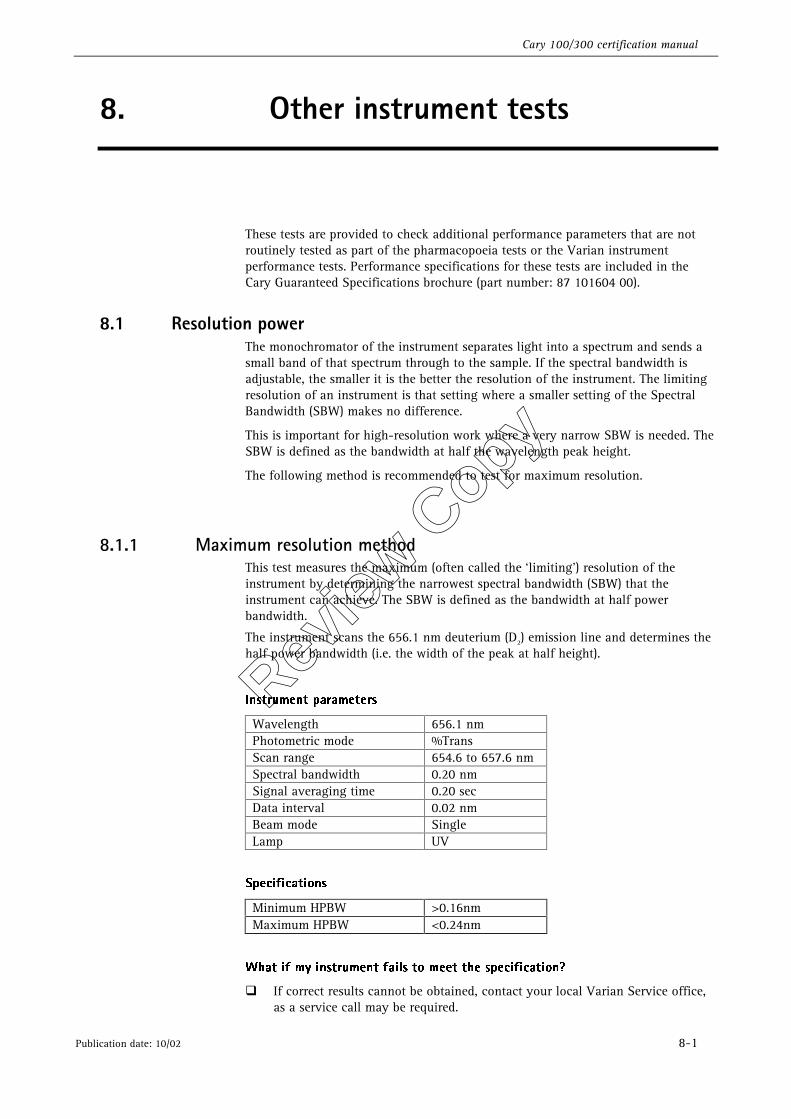
8.1.1 Maximum resolution method This test measures the maximum (often called the ‘limiting’) resolution of the instrument by determining the narrowest spectral bandwidth (SBW) that the instrument can achieve. The SBW is defined as the bandwidth at half power bandwidth.
The instrument scans the 656.1 nm deuterium (D2) emission line and determines the half power bandwidth (i.e. the width of the peak at half height).
*OTUSVNFOU�QBSBNFUFST�
Wavelength 656.1 nm Photometric mode %Trans Scan range 654.6 to 657.6 nm Spectral bandwidth 0.20 nm Signal averaging time 0.20 sec Data interval 0.02 nm Beam mode Single Lamp UV
4QFDJGJDBUJPOT�
Minimum HPBW >0.16nm Maximum HPBW <0.24nm
�
8IBU�JG�NZ�JOTUSVNFOU�GBJMT�UP�NFFU�UIF�TQFDJGJDBUJPO �
�� If correct results cannot be obtained, contact your local Varian Service office, as a service call may be required.
Review
Copy
Cary 100/300 certification manual
8-2 Publication date: 10/02
8.2 Stray light Stray light is defined as any light that gets to the detector that is not of the selected wavelength. The detector cannot distinguish between stray light and light of the selected wavelength and will add the two together to give a higher photometric reading than expected. Stray light also causes deviation from the Beer-Lambert Law. Stray light is monitored by measuring a test solution at a wavelength where the solution is totally absorbing. Any light that is detected is due to stray light.
There is one non-pharmocopoeia method to test for stray light. This is the following ASTM test method.
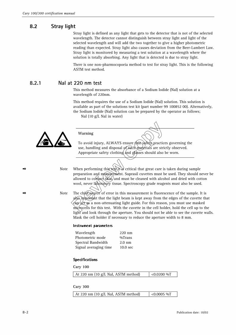
8.2.1 NaI at 220 nm test This method measures the absorbance of a Sodium Iodide (NaI) solution at a wavelength of 220nm.
This method requires the use of a Sodium Iodide (NaI) solution. This solution is available as part of the solutions test kit (part number 99 100852 00). Alternatively, the Sodium Iodide (NaI) solution can be prepared by the operator as follows; NaI (10 g/L NaI in water)
Warning
To avoid injury, ALWAYS ensure that safety practices governing the use, handling and disposal of such materials are strictly observed. Appropriate safety clothing and glasses should also be worn.
✒ Note When performing this test it is critical that great care is taken during sample preparation and measurement. Suprasil cuvettes must be used. They should never be allowed to contact skin, and must be cleaned with alcohol and dried with cotton wool, never laboratory tissue. Spectroscopy grade reagents must also be used.
✒ Note The chief source of error in this measurement is fluorescence of the sample. It is also important that the light beam is kept away from the edges of the cuvette that can act as a non-attenuating light guide. For this reason, you must use masked microcells for this test. With the cuvette in the cell holder, hold the cell up to the light and look through the aperture. You should not be able to see the cuvette walls. Mask the cell holder if necessary to reduce the aperture width to 8 mm.
*OTUSVNFOU�QBSBNFUFST�
Wavelength 220 nm Photometric mode %Trans Spectral Bandwidth 2.0 nm Signal averaging time 10.0 sec
�
4QFDJGJDBUJPOT�
Cary 100
At 220 nm (10 g/L NaI, ASTM method) <0.0200 %T
Cary 300
At 220 nm (10 g/L NaI, ASTM method) <0.0005 %T �
�
Review
Copy
Cary 100/300 certification manual
Publication date: 10/02 8-3
8IBU�JG�NZ�JOTUSVNFOU�GBJMT�UP�NFFU�UIF�TQFDJGJDBUJPO �
�� Ensure that the sample compartment is tightly sealed. Repeat the test with the room lights switched off. If the instrument passes the test, this indicates that there is a light leak in the instrument cover somewhere.
�� As the test solutions may degrade over time, the accuracy of the test depends heavily on the correct handling, management and combination of materials. Make up fresh solutions, ensuring cell cleanliness. Mask the cell holder to reduce the aperture width to 8 mm and repeat test.
�� If correct results still cannot be obtained, contact your local Varian Service office, as a service call may be required.
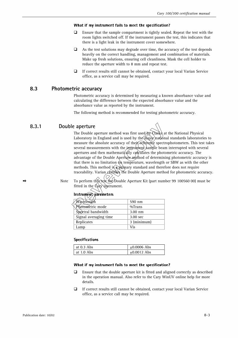
8.3 Photometric accuracy Photometric accuracy is determined by measuring a known absorbance value and calculating the difference between the expected absorbance value and the absorbance value as reported by the instrument.
The following method is recommended for testing photometric accuracy.
8.3.1 Double aperture The Double aperture method was first used by Clarke at the National Physical Laboratory in England and is used by the major national standards laboratories to measure the absolute accuracy of their reference spectrophotometers. This test takes several measurements with the instrument sample beam interrupted with several apertures and then mathematically calculates the photometric accuracy. The advantage of the Double Aperture method of determining photometric accuracy is that there is no limitation on temperature, wavelength or SBW as with the other methods. This method is a primary standard and therefore does not require traceability. Varian certifies the Double Aperture method for photometric accuracy.
✒ Note To perform this test the Double Aperture Kit (part number 99 100560 00) must be fitted in the Cary instrument.
*OTUSVNFOU�QBSBNFUFST�
Wavelength 590 nm Photometric mode %Trans Spectral bandwidth 3.00 nm Signal averaging time 3.00 sec Replicates 3 (minimum) Lamp Vis
4QFDJGJDBUJPOT�
at 0.3 Abs ±0.0006 Abs at 1.0 Abs ±0.0012 Abs
8IBU�JG�NZ�JOTUSVNFOU�GBJMT�UP�NFFU�UIF�TQFDJGJDBUJPO �
�� Ensure that the double aperture kit is fitted and aligned correctly as described in the operation manual. Also refer to the Cary WinUV online help for more details.
�� If correct results still cannot be obtained, contact your local Varian Service office, as a service call may be required.
Review
Copy
Cary 100/300 certification manual
8-4 Publication date: 10/02
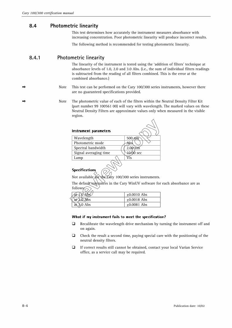
8.4 Photometric linearity This test determines how accurately the instrument measures absorbance with increasing concentration. Poor photometric linearity will produce incorrect results.
The following method is recommended for testing photometric linearity.
8.4.1 Photometric linearity The linearity of the instrument is tested using the ‘addition of filters’ technique at absorbance levels of 1.0, 2.0 and 3.0 Abs. (i.e., the sum of individual filters readings is subtracted from the reading of all filters combined. This is the error at the combined absorbance.)
✒ Note This test can be performed on the Cary 100/300 series instruments, however there are no guaranteed specifications provided.
✒ Note The photometric value of each of the filters within the Neutral Density Filter Kit (part number 99 100561 00) will vary with wavelength. The marked values on these Neutral Density Filters are approximate values only when measured in the visible region.
�
*OTUSVNFOU�QBSBNFUFST�
Wavelength 500 nm Photometric mode Abs Spectral bandwidth 2.00 nm Signal averaging time 10.00 sec Lamp Vis
�
4QFDJGJDBUJPOT�
Not available for the Cary 100/300 series instruments.
The default tolerances in the Cary WinUV software for each absorbance are as follows:
at 1.0 Abs ±0.0010 Abs at 2.0 Abs ±0.0018 Abs at 2.0 Abs ±0.0081 Abs
8IBU�JG�NZ�JOTUSVNFOU�GBJMT�UP�NFFU�UIF�TQFDJGJDBUJPO �
�� Recalibrate the wavelength drive mechanism by turning the instrument off and on again.
�� Check the result a second time, paying special care with the positioning of the neutral density filters.
�� If correct results still cannot be obtained, contact your local Varian Service office, as a service call may be required.
Review
Copy
Cary 100/300 certification manual
Publication date: 10/02 8-5
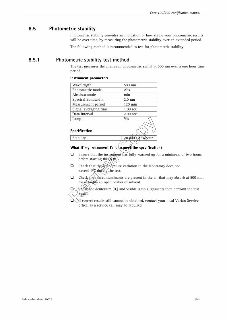
8.5 Photometric stability Photometric stability provides an indication of how stable your photometric results will be over time, by measuring the photometric stability over an extended period.
The following method is recommended to test for photometric stability.
8.5.1 Photometric stability test method The test measures the change in photometric signal at 500 nm over a one hour time period.
*OTUSVNFOU�QBSBNFUFST�
Wavelength 500 nm Photometric mode Abs Abscissa mode min Spectral Bandwidth 2.0 nm Measurement period 120 min Signal averaging time 1.00 sec Data interval 2.00 sec Lamp Vis
�
4QFDJGJDBUJPO��
Stability <0.0003 Abs/hour 8IBU�JG�NZ�JOTUSVNFOU�GBJMT�UP�NFFU�UIF�TQFDJGJDBUJPO �
�� Ensure that the instrument has fully warmed up for a minimum of two hours before starting this test.
�� Check that the temperature variation in the laboratory does not exceed 2OC during the test.
�� Check that no contaminants are present in the air that may absorb at 500 nm; for example an open beaker of solvent.
�� Check the deuterium (D2) and visible lamp alignments then perform the test again.
�� If correct results still cannot be obtained, contact your local Varian Service office, as a service call may be required. Rev
iew C
opy
Cary 100/300 certification manual
8-6 Publication date: 10/02
8.6 Photometric noise Photometric noise is a measure of the signal to noise ratio of the instrument. The higher the noise, the harder it is to distinguish between small changes in the signal and the noise of the system. The noise level indicates the stability of a reading. It determines the precision of the measurement and the detection limit of the instrument. Poor signal-to-noise performance makes it very difficult to determine the actual absorption value as it fluctuates. It introduces errors into both quantitative and qualitative spectroscopy.
This method provides an extension of the photometric noise test offered in the Instrument performance tests and allows measurements at up to 3.0 Abs for the Cary 100 instrument and up to 5.0 Abs for the Cary 300 instrument.
8.6.1 Photometric noise method This test measures the photometric noise (specified as Absorbance Root Mean Square [RMS], which is approximately one fifth of the peak to peak value) over a two minute period.
✒ Note To perform this test at 3.0 to 5.0 Absorbance, you will be prompted to ensure there is approximately 1.6 Abs of rear beam attenuation. You can achieve the appropriate rear beam attenuation by either one of the following methods;
�� the Rear Beam Attenuator (RBA) accessory (part number 00 100411 00) for up to 1.7 Abs
��a UV-Vis Filter Set (part number 99 100477 00) for up to 3.0 Abs ��a solution that absorbs the correct Abs (1.5 Abs) at the required wavelength
*OTUSVNFOU�QBSBNFUFST�
Wavelength 500 nm Photometric mode Abs Abscissa mode Min Spectral bandwidth 2.00 nm Scan period 1.00 min Signal averaging time 1.00 sec Lamp Vis
4QFDJGJDBUJPOT�
Cary 100 (at 500 nm)
0 Abs <0.000085 Abs 1 Abs <0.000200 Abs 2 Abs <0.000300 Abs 3 Abs <0.000400 Abs
with 1.6 Abs rear beam attenuation.
Review
Copy
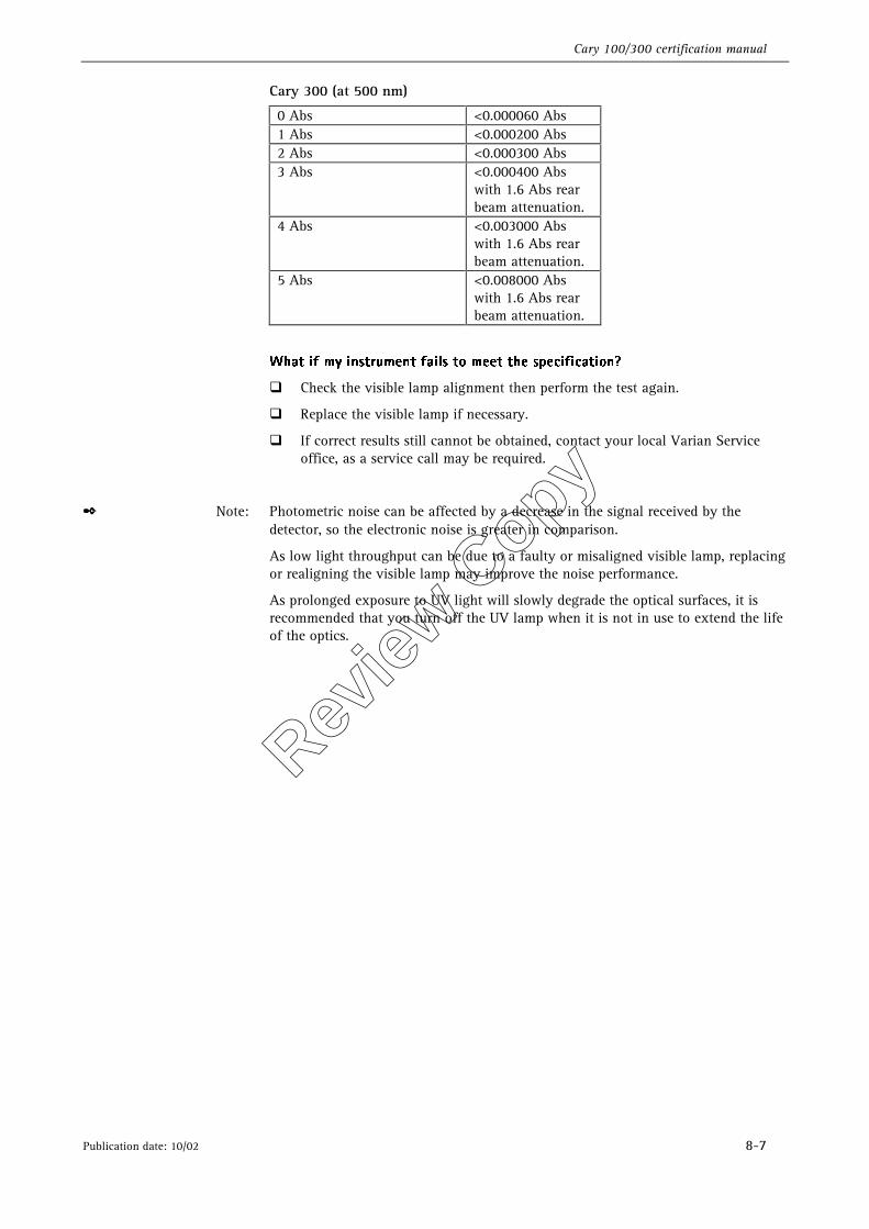
Cary 100/300 certification manual
Publication date: 10/02 8-7
Cary 300 (at 500 nm)
0 Abs <0.000060 Abs 1 Abs <0.000200 Abs 2 Abs <0.000300 Abs 3 Abs <0.000400 Abs
with 1.6 Abs rear beam attenuation.
4 Abs <0.003000 Abs with 1.6 Abs rear beam attenuation.
5 Abs <0.008000 Abs with 1.6 Abs rear beam attenuation.
8IBU�JG�NZ�JOTUSVNFOU�GBJMT�UP�NFFU�UIF�TQFDJGJDBUJPO �
�� Check the visible lamp alignment then perform the test again.
�� Replace the visible lamp if necessary.
�� If correct results still cannot be obtained, contact your local Varian Service office, as a service call may be required.
✒ Note: Photometric noise can be affected by a decrease in the signal received by the detector, so the electronic noise is greater in comparison.
As low light throughput can be due to a faulty or misaligned visible lamp, replacing or realigning the visible lamp may improve the noise performance.
As prolonged exposure to UV light will slowly degrade the optical surfaces, it is recommended that you turn off the UV lamp when it is not in use to extend the life of the optics.
Review
Copy
Cary 100/300 certification manual
8-8 Publication date: 10/02
This page is intentionally left blank
Review
Copy
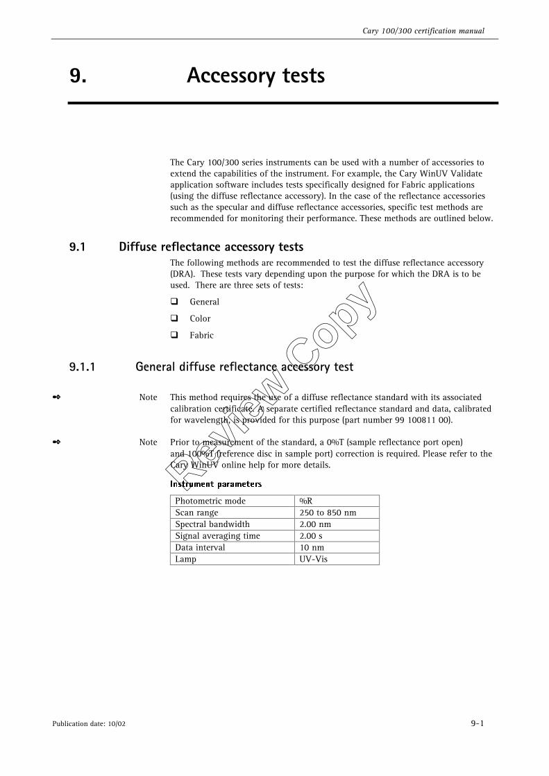
Cary 100/300 certification manual
Publication date: 10/02 9-1
9. Accessory tests
The Cary 100/300 series instruments can be used with a number of accessories to extend the capabilities of the instrument. For example, the Cary WinUV Validate application software includes tests specifically designed for Fabric applications (using the diffuse reflectance accessory). In the case of the reflectance accessories such as the specular and diffuse reflectance accessories, specific test methods are recommended for monitoring their performance. These methods are outlined below.
9.1 Diffuse reflectance accessory tests The following methods are recommended to test the diffuse reflectance accessory (DRA). These tests vary depending upon the purpose for which the DRA is to be used. There are three sets of tests:
�� General
�� Color
�� Fabric
9.1.1 General diffuse reflectance accessory test
✒ Note This method requires the use of a diffuse reflectance standard with its associated calibration certificate. A separate certified reflectance standard and data, calibrated for wavelength, is provided for this purpose (part number 99 100811 00).
✒ Note Prior to measurement of the standard, a 0%T (sample reflectance port open) and 100%T (reference disc in sample port) correction is required. Please refer to the Cary WinUV online help for more details.
*OTUSVNFOU�QBSBNFUFST�
Photometric mode %R Scan range 250 to 850 nm Spectral bandwidth 2.00 nm Signal averaging time 2.00 s Data interval 10 nm Lamp UV-Vis
�
Review
Copy
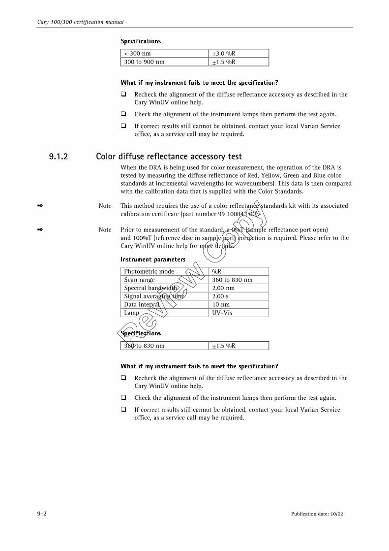
Cary 100/300 certification manual
9-2 Publication date: 10/02
4QFDJGJDBUJPOT�
< 300 nm ±3.0 %R 300 to 900 nm ±1.5 %R
�
8IBU�JG�NZ�JOTUSVNFOU�GBJMT�UP�NFFU�UIF�TQFDJGJDBUJPO �
�� Recheck the alignment of the diffuse reflectance accessory as described in the Cary WinUV online help.
�� Check the alignment of the instrument lamps then perform the test again.
�� If correct results still cannot be obtained, contact your local Varian Service office, as a service call may be required.
9.1.2 Color diffuse reflectance accessory test When the DRA is being used for color measurement, the operation of the DRA is tested by measuring the diffuse reflectance of Red, Yellow, Green and Blue color standards at incremental wavelengths (or wavenumbers). This data is then compared with the calibration data that is supplied with the Color Standards.
✒ Note This method requires the use of a color reflectance standards kit with its associated calibration certificate (part number 99 100843 00).
✒ Note Prior to measurement of the standard, a 0%T (sample reflectance port open) and 100%T (reference disc in sample port) correction is required. Please refer to the Cary WinUV online help for more details.
*OTUSVNFOU�QBSBNFUFST�
Photometric mode %R Scan range 360 to 830 nm Spectral bandwidth 2.00 nm Signal averaging time 2.00 s Data interval 10 nm Lamp UV-Vis
�
4QFDJGJDBUJPOT�
360 to 830 nm ±1.5 %R
8IBU�JG�NZ�JOTUSVNFOU�GBJMT�UP�NFFU�UIF�TQFDJGJDBUJPO �
�� Recheck the alignment of the diffuse reflectance accessory as described in the Cary WinUV online help.
�� Check the alignment of the instrument lamps then perform the test again.
�� If correct results still cannot be obtained, contact your local Varian Service office, as a service call may be required.
Review
Copy
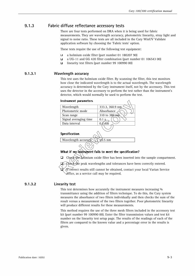
Cary 100/300 certification manual
Publication date: 10/02 9-3
9.1.3 Fabric diffuse reflectance accessory tests There are four tests performed on DRA when it is being used for fabric measurements. They are wavelength accuracy, photometric linearity, stray light and signal to noise ratio. These tests are all included in the Cary WinUV Validate application software by choosing the ’Fabric tests’ option.
These tests require the use of the following test equipment:
�� a holmium oxide filter (part number 01 180207 90) �� a UG-11 and GG 420 filter combination (part number 01 106543 00) �� linearity test filters (part number 99 100990 00)
9.1.3.1 Wavelength accuracy This test uses the holmium oxide filter. By scanning the filter, this test monitors how close the indicated wavelength is to the actual wavelength. The wavelength accuracy is determined by the Cary instrument itself, not by the accessory. This test uses the detector in the accessory to perform the test rather than the instrument’s detector, which would normally be used to perform the test.
*OTUSVNFOU�QBSBNFUFST�
Wavelength 333.3, 360.9 nm Photometric mode Absorbance Scan range 310 to 380 nm Signal averaging time 0.1 s Data interval 0.2 nm
�
4QFDJGJDBUJPO�
Wavelength accuracy ±0.5 nm
8IBU�JG�NZ�JOTUSVNFOU�GBJMT�UP�NFFU�UIF�TQFDJGJDBUJPO �
��Check the holmium oxide filter has been inserted into the sample compartment.
��Check the peak wavelengths and tolerances have been correctly entered.
��If correct results still cannot be obtained, contact your local Varian Service office, as a service call may be required.
9.1.3.2 Linearity test This test determines how accurately the instrument measures increasing % transmittance using the addition of filters technique. To do this, the Cary system measures the absorbance of two filters individually and then checks the sum of the result versus a measurement of the two filters together. Poor photometric linearity will produce different results for these measurements.
This method requires the use of the three mesh filters included in the accessory test kit (part number 99 100990 00). Enter the filter transmission values and test kit number on the linearity test setup page. The results of the readings of each of the filters are compared to the known value and a percentage error in the results is given.
Review
Copy
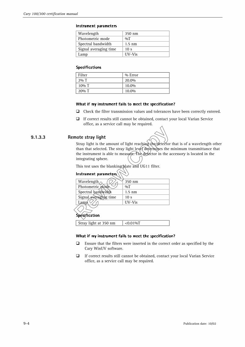
Cary 100/300 certification manual
9-4 Publication date: 10/02
*OTUSVNFOU�QBSBNFUFST�
Wavelength 350 nm Photometric mode %T Spectral bandwidth 1.5 nm Signal averaging time 10 s Lamp UV-Vis
�
4QFDJGJDBUJPOT�
Filter % Error 2% T 20.0% 10% T 10.0% 20% T 10.0%
�
8IBU�JG�NZ�JOTUSVNFOU�GBJMT�UP�NFFU�UIF�TQFDJGJDBUJPO �
��Check the filter transmission values and tolerances have been correctly entered.
��If correct results still cannot be obtained, contact your local Varian Service office, as a service call may be required.
9.1.3.3 Remote stray light Stray light is the amount of light reaching the detector that is of a wavelength other than that selected. The stray light level determines the minimum transmittance that the instrument is able to measure. The detector in the accessory is located in the integrating sphere.
This test uses the blanking plate and UG11 filter.
*OTUSVNFOU�QBSBNFUFST�
Wavelength 350 nm Photometric mode %T Spectral bandwidth 1.5 nm Signal averaging time 10 s Lamp UV-Vis
�
4QFDJGJDBUJPO�
Stray light at 350 nm <0.01%T
8IBU�JG�NZ�JOTUSVNFOU�GBJMT�UP�NFFU�UIF�TQFDJGJDBUJPO �
�� Ensure that the filters were inserted in the correct order as specified by the Cary WinUV software.
�� If correct results still cannot be obtained, contact your local Varian Service office, as a service call may be required.
Review
Copy
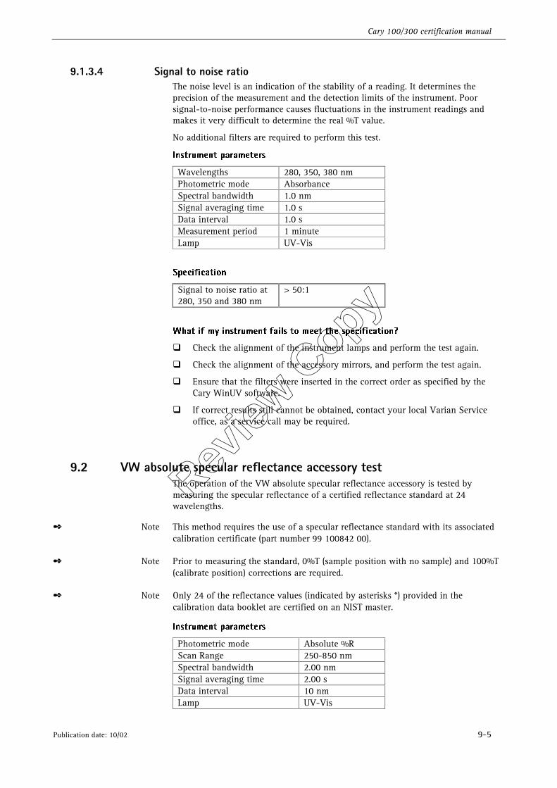
Cary 100/300 certification manual
Publication date: 10/02 9-5
9.1.3.4 Signal to noise ratio The noise level is an indication of the stability of a reading. It determines the precision of the measurement and the detection limits of the instrument. Poor signal-to-noise performance causes fluctuations in the instrument readings and makes it very difficult to determine the real %T value.
No additional filters are required to perform this test.
*OTUSVNFOU�QBSBNFUFST�
Wavelengths 280, 350, 380 nm Photometric mode Absorbance Spectral bandwidth 1.0 nm Signal averaging time 1.0 s Data interval 1.0 s Measurement period 1 minute Lamp UV-Vis
4QFDJGJDBUJPO�
Signal to noise ratio at 280, 350 and 380 nm
> 50:1
�
8IBU�JG�NZ�JOTUSVNFOU�GBJMT�UP�NFFU�UIF�TQFDJGJDBUJPO �
�� Check the alignment of the instrument lamps and perform the test again.
�� Check the alignment of the accessory mirrors, and perform the test again.
�� Ensure that the filters were inserted in the correct order as specified by the Cary WinUV software.
�� If correct results still cannot be obtained, contact your local Varian Service office, as a service call may be required.
9.2 VW absolute specular reflectance accessory test The operation of the VW absolute specular reflectance accessory is tested by measuring the specular reflectance of a certified reflectance standard at 24 wavelengths.
✒ Note This method requires the use of a specular reflectance standard with its associated calibration certificate (part number 99 100842 00).
✒ Note Prior to measuring the standard, 0%T (sample position with no sample) and 100%T (calibrate position) corrections are required.
✒ Note Only 24 of the reflectance values (indicated by asterisks *) provided in the calibration data booklet are certified on an NIST master.
*OTUSVNFOU�QBSBNFUFST�
Photometric mode Absolute %R Scan Range 250-850 nm Spectral bandwidth 2.00 nm Signal averaging time 2.00 s Data interval 10 nm Lamp UV-Vis
�
Review
Copy
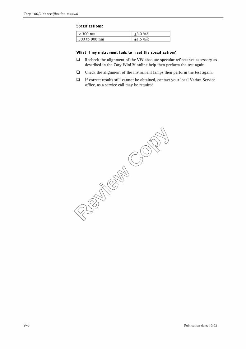
Cary 100/300 certification manual
9-6 Publication date: 10/02
4QFDJGJDBUJPOT��
< 300 nm ±3.0 %R 300 to 900 nm ±1.5 %R
�
8IBU�JG�NZ�JOTUSVNFOU�GBJMT�UP�NFFU�UIF�TQFDJGJDBUJPO �
�� Recheck the alignment of the VW absolute specular reflectance accessory as described in the Cary WinUV online help then perform the test again.
�� Check the alignment of the instrument lamps then perform the test again.
�� If correct results still cannot be obtained, contact your local Varian Service office, as a service call may be required.
Review
Copy
Cary 100/300 certification manual
Publication date: 10/02 10-1
10. Care and handling
To maintain optimum optical and reflectance properties of the optical standards, the following care and cleaning instructions must be followed.
10.1 General care Although the materials used for these standards are quite durable, care should be taken to prevent contaminants, such as finger oils, from contacting the material surface. Always wear clean gloves when handling these materials.
The liquid standards must not be allowed to freeze and it is recommended that they be stored within the temperature range of 5 to 50o Celsius.
10.2 Cleaning the liquid standards Dirty cells are the greatest single source of error in spectrophotometry. Avoid handling the cells by the polished surfaces. In the event of the faces becoming contaminated, clean by soaking in a neutral detergent solution according to the manufacturer’s instructions, rinse thoroughly with de-ionized water and dry with ethanol. DO NOT use acetone.
Solution spillage should never be allowed to dry on the cells, and should be wiped off with a soft tissue paper or lint free cloth.
Review
Copy
Cary 100/300 certification manual
10-2 Publication date: 10/02
10.3 Re-calibrating the liquid standards Starna, the recommended supplier of liquid standards, recommend that their liquid standards sets be recalibrated every two years. However, most accreditation authorities require that standards be recalibrated at least once per year. The calibration of the liquid standards does not usually change significantly within this time interval unless the cell becomes cracked, marked or scratched and will then require repolishing to restore its accuracy.
For recalibration of the Starna liquid standards, please contact your nearest Starna distributor:
Starna Pty Ltd PO Box 113 Thornleigh NSW 2120 AUSTRALIA
Optiglass Ltd. 52/54 Fowler Road Hainault Industrial Estate HAINAULT ESSEX 1G6 3UT ENGLAND
FREE CALL: 1 800 252 284 Telephone: +61-2-9484-0033 Facsimile: +61-2-9484-0055 Email: [email protected] Web site: www.starna.com.au
Telephone: 44 (0) 181 501 5550 Facsimile: 44 (0) 181 501 1118 Email: [email protected] Web site: www.optiglass.co.uk
Starna Cells Inc. 5950 Traffic Way ATASCADERO CA 93423 USA
Starna GmbH Schillerstrasse 10A D-64311 Pfungstadt GERMANY
Telephone: 1 805 466 8855 Facsimile: Email: [email protected] Web site: www.starna.com
Telephone: 06157 7953 Facsimile: 06157 85564
Starna Ges.mbH Wien Postfach 9 A-8225 Pollauberg AUSTRIA
Telephone: 03335 4850 Facsimile: 03335 4851 Email: [email protected]
Review
Copy
Cary 100/300 certification manual
Publication date: 10/02 10-3
10.4 Ordering NIST reference materials Purchase orders (in English) for all NIST SRMs/ RMs should be directed to:
National Institute of Standards and Technology Standard Reference Materials Program 100 Bureau Drive, Stop 2322 Gaithersburg, MD 20899-2322 USA
Telephone: +1-301-975-6776 Facsimile: +1-301-948-3730 Email: [email protected] Web site: http://www.nist.gov
Each purchase order should give the number of units, catalogue number, and name of each reference material requested.
Example: 1 each, SRM 930E, Glass Filter Set, Transmittance
The following information must be included with each order:
�� a billing address, �� a shipping address, �� name of customer, �� telephone number, �� fax number, �� purchase order number,
For US customers also include,
�� a customer identification number, i.e., a social security number (SSN) for consumer customers,
�� tax identification number (TIN) for commercial customers, or �� agency code (ALC) for U.S. government customers.
10.5 Re-calibrating the NIST Filter standards For recalibration of the NIST filter standards, please contact your nearest NIST distributor. Or contact:
National Institute of Standards and Technology Calibrations Program 100 Bureau Drive, Stop 2330 Gaithersburg, MD 20899-2330 USA
Telephone: +1-301-975-2002 Facsimile: +1-301-869-3548 Email: [email protected] Web site: http://www.nist.gov
Review
Copy
Cary 100/300 certification manual
10-4 Publication date: 10/02
10.6 Cleaning the diffuse reflectance standards If the surface of the standards material should ever become contaminated, it may be blown clean with a jet of clean dry air or nitrogen. Do not use Freon. If this is not sufficient, then the material surface can be sanded under running water with 220-240 grit water proof emery cloth until the surface is totally hydrophobic (the water beads and runs off the material immediately). If the material is grossly contaminated or scratched, then the material surface can be sanded with 220-320 grit wet sand paper under a stream of running water. The materials surface should then be blown dry with clean dry air or nitrogen, or alternatively allow the material to air dry.
✒ Note For low reflectance material (i.e. <10%) sand it dry rather than under running water.
If the standard material is required to have high resistance to deep UV radiation, the material should also be prepared as follows,
Flush the material with >18 mohm distilled, deionised water for 24 hours.
Vacuum bake the material at 75°C for 12 hours at approximately 1 Torr, then purge the vacuum oven with clean dry air or nitrogen.
10.7 Re-calibrating the diffuse reflectance standards Labsphere recommends that their standards be recalibrated at least once per year, sooner if the standards are visibly soiled or damaged. Recalibrations will be completed within two weeks of receipt of the standards. Call Labsphere for pricing information - prices depend on each type of standard to be recalibrated.
For recalibration of the Labsphere standards, please contact your nearest Labsphere distributor. Or contact;
Labsphere P.O. Box 70 Shaker Street North Sutton, New Hampshire 03260 USA
Telephone: +1-603-927-4266 Facsimile: +1-603-927-4694
✒ Note Be ready to give Labsphere the serial number of the standards to be recalibrated.
Review
Copy
Cary 100/300 certification manual
Publication date: 10/02 11-1
11. Certification kit log sheet
The following certification kit log sheet can be used to record the recertification history of the certification kits used with this package (if appropriate).
Review
Copy
Cary 100/300 certification manual
11-2 Publication date: 10/02
This page is intentionally left blank
Review
Copy
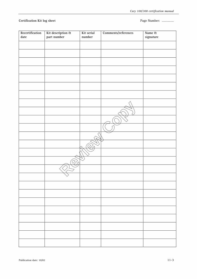
Cary 100/300 certification manual
Publication date: 10/02 11-3
Certification Kit log sheet Page Number: ……………
Recertification date
Kit description & part number
Kit serial number
Comments/references Name & signature
Review
Copy
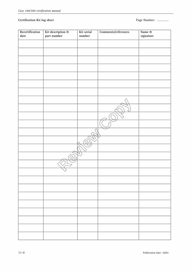
Cary 100/300 certification manual
11-4 Publication date: 10/02
Certification Kit log sheet Page Number: ……………
Recertification date
Kit description & part number
Kit serial number
Comments/references Name & signature
Review
Copy